
Research & Innovation Center / National Energy Technology ......
40
Task 5.0 - Resource Assessment Angela Goodman Research & Innovation Center / National Energy Technology Laboratory U.S. Department of Energy National Energy Technology Laboratory Mastering the Subsurface Through Technology Innovation, Partnerships and Collaboration: Carbon Storage and Oil and Natural Gas Technologies Review Meeting August 1-3, 2017
Transcript of Research & Innovation Center / National Energy Technology ......

Task 5.0 - Resource Assessment
Angela GoodmanResearch & Innovation Center /
National Energy Technology Laboratory
U.S. Department of EnergyNational Energy Technology Laboratory
Mastering the Subsurface Through Technology Innovation, Partnerships and Collaboration:Carbon Storage and Oil and Natural Gas Technologies Review Meeting
August 1-3, 2017

2
Presentation Outline
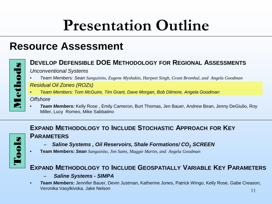
DEVELOP DEFENSIBLE DOE METHODOLOGY FOR REGIONAL ASSESSMENTSUnconventional Systems• Team Members: Sean Sanguinito, Eugene Myshakin, Harpeet Singh, Grant Bromhal, and Angela GoodmanResidual Oil Zones (ROZs)• Team Members: Tom McGuire, Tim Grant, Dave Morgan, Bob Dilmore, Angela GoodmanOffshore• Team Members: Kelly Rose , Emily Cameron, Burt Thomas, Jen Bauer, Andrew Bean, Jenny DeGiulio, Roy
Miller, Lucy Romeo, Mike Sabbatino
EXPAND METHODOLOGY TO INCLUDE STOCHASTIC APPROACH FOR KEYPARAMETERS
– Saline Systems , Oil Reservoirs, Shale Formations/ CO2 SCREEN• Team Members: Sean Sanguinito, Jim Sams, Maggie Martin, and Angela Goodman
EXPAND METHODOLOGY TO INCLUDE GEOSPATIALLY VARIABLE KEY PARAMETERS– Saline Systems - SIMPA
• Team Members: Jennifer Bauer, Devin Justman, Katherine Jones, Patrick Wingo, Kelly Rose, Gabe Creason, Veronika Vasylkivska, Jake Nelson
Resource Assessment
Met
hods
Tools

3
R fi f Oil M h
Pair-wise Differences A B C D E F G H I J K L MUSGS - CSLF
USGS - AtlasI,IIUSGS - AtlasIII,IV
USGS - Szulc.USGS - Zhou
CSLF - AtlasI,IICSLF - AtlasIII,IV
CSLF - Szulc.CSLF - Zhou
AtlasI,II - AtlasIII,IVAtlasI,II - Szulc.AtlasI,II - Zhou
AtlasIII,IV - Szulc.AtlasIII,IV - Zhou
Szulc. - Zhou*white boxes represent statistical differences
Formation
References:1 Goodman, A; Hakala, A; Bromhal, G; Deel, D; Rodosta, T; Frailey, S; Small, M; Allen, D; Romanov, V; Fazio, J; Huerta, N; McIntyre, D; Kutchko, B; Guthrie, G “US DOE methodology for the development of geologic storage potential for carbon dioxide at the national and regional scale” International Journal of Greenhouse Gas Control 2011, 5, 4, 952-965. cited 63 times (viewed >1882 times) 2 Olga H. Popova, Mitchell Small, Sean T. McCoy, Andrew C. Thomas, Bobak Karimi, Angela Goodman, and Kristin M. Carter “Comparative Analysis of Carbon Dioxide Storage Resource Assessments Methodologies” Environmental Geosciences 2012, 19, 3, 105-124. cited >5 times3 Goodman, Angela; Bromhal, Grant; Strazisar, Brian; Rodosta, Traci; Guthrie, William; Allen, Doug, Guthrie, George “Comparison of methods for geologic storage of carbon dioxide in saline formations” International Journal of Greenhouse Gas Control 2013, 18, 329–342. cited 12 times (viewed >851 times)4 Popova, O.; Small, M.; McCoy, S.; Thomas, A.; Rose, S.; Karimi, B.; Carter, K.; Goodman, A. “Spatial Stochastic Modeling of Sedimentary Formations to Assess CO2 Storage Potential” Environmental Science & Technology 2014, 48, 6247-6255 cited 3 times5 Goodman, Angela; Fukai, Isis; Dilmore, Robert; Frailey, Scott; Bromhal, Grant; Soeder, Dan; Gorecki, Charlie; Peck, Wesley; Rodosta, Traci; Guthrie, George “Methodology for assessing CO2 storage potential of organic-rich shale formations” Energy Procedia 2014, 63, 5178-5184 cited >2 times (viewed >422 times)
6 Sanguinito, S., Goodman, A., Levine, J.S., 2016, NETL CO2 Storage prospective Resource Estimation Excel aNalysis (CO2-SCREEN) User’s Manual; NETL-TRS-X-2016; Technical Report Series; U.S. Department of Energy, National Energy Technology Laboratory: Pittsburgh, PA, 2016; p. 31. https://edx.netl.doe.gov/carbonstorage/?page_id=9147 Goodman, A., Sanguinito, S., Levine, J. Prospective CO2 Saline Resource Estimation Methodology: Refinement of Existing DOE-NETL Methods Based on Data Availability, International Journal of Greenhouse Gas Control, 2016, 54, 242-249 (viewed >100 times)8Levine, J. S., Fukai, I. Soeder, D. J., Bromhal, G., Dilmore, R.M., Guthrie, G. D., Rodosta, T., Sanguinito, S., Frailey, S., Gorecki, D., Peck, W. and Goodman, A.L. “U.S. DOE NETL Methodology for Estimating the Prospective CO2 Storage Resource of Shales at the National and Regional Scale” International Journal of Greenhouse Gas Control, 2016, 51, 81-94. cited >1 times (viewed >368 times)9Evgeniy M. Myshakin, Harpreet Singh, Sean Sanguinito, Grant Bromhal, Angela L. Goodman Simulated Efficiency Factors for Estimating the Prospective CO2 Storage Resource of Shales, accepted to the International Journal of Greenhouse Gas Control, 201710Robert Dilmore, Russel Johns, Nicholas A. Azzolina, Angela L. Goodman U.S. DOE NETL Methodology for Estimating the Assessment of CO2 Storage Potential in Oil Reservoirs, accepted to the International Journal of Greenhouse Gas Control, 2017
Development of DOE Defensible CO2 Storage Methods

Technical Status
4

5
Presentation Outline
DEVELOP DEFENSIBLE DOE METHODOLOGY FOR REGIONAL ASSESSMENTSUnconventional Systems• Team Members: Sean Sanguinito, Eugene Myshakin, Harpeet Singh, Grant Bromhal, and Angela GoodmanResidual Oil Zones (ROZs)• Team Members: Tom McGuire, Tim Grant, Dave Morgan, Bob Dilmore, Angela GoodmanOffshore• Team Members: Kelly Rose , Emily Cameron, Burt Thomas, Jen Bauer, Andrew Bean, Jenny DeGiulio, Roy
Miller, Lucy Romeo, Mike Sabbatino
EXPAND METHODOLOGY TO INCLUDE STOCHASTIC APPROACH FOR KEYPARAMETERS
– Saline Systems , Oil Reservoirs, Shale Formations/ CO2 SCREEN• Team Members: Sean Sanguinito, Jim Sams, Maggie Martin, and Angela Goodman
EXPAND METHODOLOGY TO INCLUDE GEOSPATIALLY VARIABLE KEY PARAMETERS– Saline Systems - SIMPA
• Team Members: Jennifer Bauer, Devin Justman, Katherine Jones, Patrick Wingo, Kelly Rose, Gabe Creason, Veronika Vasylkivska, Jake Nelson
Resource Assessment
Met
hods
Tools

Unconventional Systems
6
• Majority of shale formations will serve as reservoir seals for stored anthropogenic CO2
• Prospective shale formations require: 1. Prior hydrocarbon production using horizontal
drilling and stimulation via staged, high-volume hydraulic fracturing
2. Depths sufficient to maintain CO2 in a supercritical state, generally >800 m
3. Over-lying seal
• Storage of CO2 in shale as a • Free fluid phase within fractures and matrix
pores • Sorbed phase on organic and inorganic matter
• US-DOE-NETL methodology for screening-level assessment of prospective CO2 storage resources in shale using a volumetric equation.
• Volumetric resource estimates are produced from the bulk volume, porosity, and sorptivity of the shale and storage efficiency factors based on formation-scale properties and petrophysical limitations on fluid transport.
Shale Method

Volumetric EquationGCO2 CO2 storage resource (mass) of the shale formation
At Total area (map view) of the shale formation being assessed for CO2 storage hg Gross thickness of the shale formation Ve Net effective volume of the formation (𝐴𝐴𝑡𝑡𝐸𝐸𝐴𝐴ℎ𝑔𝑔𝐸𝐸ℎ )
ρCO2
φ Density of CO2 at the pressure (𝑃𝑃�) and temperature (𝑇𝑇�) of Ve prior to production Percentage of bulk volume that is void volume
𝜌𝜌𝑠𝑠𝑠𝑠𝑠𝑠2 Maximum mass of CO2 sorbed per unit volume solid rock, e.g. the asymptotic value of a adsorption isotherm
𝐸𝐸𝐴𝐴 Fraction of shale formation total area available for CO2 storage 𝐸𝐸ℎ Fraction of shale formation gross thickness available for CO2 storage 𝐸𝐸ϕ Fraction of shale porosity within the net effective volume of the formation, Ve, available for
CO2 storage. This is a reservoir scale efficiency factor that is meant to address the probability that CO2 will never reach some of the pore space due to transport heterogeneities associated with fracture networks and low matrix permeability.
𝐸𝐸𝑆𝑆 Fraction of the total potential sorbed volume of CO2 within the net effective volume of the formation, Ve. This is a reservoir scale efficiency factor that is meant to address both transport and sorption inefficiencies. 𝐸𝐸𝑆𝑆 = 𝐸𝐸𝑚𝑚𝐸𝐸𝑠𝑠𝑠𝑠𝑠𝑠𝑠𝑠
𝐸𝐸𝑚𝑚 Fraction of the shale matrix within the effective volume of the formation, Ve, available for CO2 storage. This is a reservoir scale efficiency factor that is meant to address the probability that CO2 will never reach some of the shale matrix rock due to transport heterogeneities associated with fracture networks and low matrix permeability.
𝐸𝐸𝑠𝑠𝑠𝑠𝑠𝑠𝑠𝑠 Fraction of 𝜌𝜌𝑠𝑠𝑠𝑠𝑠𝑠2 due to reductions in sorptive packing at reservoir pressure and temperature conditions. This is a reservoir scale efficiency factor that is meant to address the inefficiency of sorptive packing on shale matrix rock due to competitive sorption (sorption/desorption with other species) and non-ideality of sorption surfaces (reduction of surface coverage) in the shale matrix.
𝐺𝐺𝐶𝐶𝐶𝐶2 = 𝐴𝐴𝑡𝑡ℎ𝑔𝑔 𝜙𝜙𝜌𝜌𝐶𝐶𝐶𝐶2 + 1 − 𝜙𝜙 𝜌𝜌𝑠𝑠𝐶𝐶𝐶𝐶2
𝐺𝐺𝐶𝐶𝐶𝐶2 = 𝐴𝐴𝑡𝑡𝐸𝐸𝐴𝐴ℎ𝑔𝑔𝐸𝐸ℎ 𝜌𝜌𝐶𝐶𝐶𝐶2𝜙𝜙𝐸𝐸𝜙𝜙 + 𝜌𝜌𝑠𝑠𝐶𝐶𝐶𝐶2 1 − 𝜙𝜙)𝐸𝐸𝑆𝑆
𝐺𝐺𝐶𝐶𝐶𝐶2 = 𝐴𝐴𝑡𝑡𝐸𝐸𝐴𝐴ℎ𝑔𝑔𝐸𝐸ℎ 𝜌𝜌𝐶𝐶𝐶𝐶2𝜙𝜙𝐸𝐸𝜙𝜙 + 𝜌𝜌𝑠𝑠𝐶𝐶𝐶𝐶2 1 − 𝜙𝜙)𝐸𝐸𝑚𝑚𝐸𝐸𝑠𝑠𝑠𝑠𝑠𝑠𝑠𝑠
Unconventional Systems
(1) Free phase storage in stimulated reservoir fractures, natural fractures and
matrix pores
(2) Solid phase storage on kerogen & clay components
Efficiency: fraction of the total formation volume that will be accessed for CO2 storage
Effective Volume

Simulated Shale Efficiency FactorsUnconventional Systems
8
𝐺𝐺𝐶𝐶𝐶𝐶2(𝑡𝑡) = 𝐴𝐴𝑡𝑡𝐸𝐸𝐴𝐴ℎ𝑔𝑔𝐸𝐸ℎ 𝜌𝜌𝐶𝐶𝐶𝐶2𝜙𝜙𝐸𝐸𝜙𝜙(𝑡𝑡) + 𝜌𝜌𝑠𝑠𝐶𝐶𝐶𝐶2 1 − 𝜙𝜙)𝐸𝐸𝑆𝑆(𝑡𝑡
�𝐸𝐸𝜙𝜙(𝑡𝑡 is a fraction of a maximum gas volume stored in a net effective volume of the formation at time t..
is a fraction of a maximum sorptivecapacity in a net effective volume of the formation at time t.
)𝐸𝐸𝑆𝑆(𝑡𝑡
Different shapes of hydraulic fractures (in red)
(rectangular) (oval-like)
Parameter Symbol SettingsLOW (L) HIGH (H)
Density of natural fracture center points D 6.35 x10⁻⁵ / 3.81 x10⁻⁵ m-2*
(2.083x10-4 / 1.250x10⁻⁴ ft-2)2.03 x10⁻⁴ / 1.91 x10-4*
(6.670x10-4 / 6.250x10⁻⁴)
Langmuir volume V 3.40 m3/ton (120 scf/ton) 9.35 (330)Injection pressure I 20.68 MPa (3000 psia) 27.58 (4000)Initial reservoir pressure R 3.45 MPa (500 psia) 6.90 (1000)Thickness T 30 m (100 ft) 152 (500)Matrix porosity P 0.045 0.125Matrix permeability M 5.92 x 10⁻²¹ m2 (6 nD) 5.92 x 10⁻¹⁹ (600)Shape of hydraulic fracture representation SH Thee different shapes (figures to the right)

Simulated Shale Efficiency FactorsUnconventional Systems
0 10 20 30 40 50 60
0.2
0.3
0.4
0.5
0.6
years
ES fr
ee g
as(t
)
0 10 20 30 40 50 60
0.1
0.2
0.3
0.4
0.5
0.6
years
ES so
rb(t
)
Pressure distributions in the middle horizontal plane of the shale reservoir model after 60 years of injection using the rectangular shape of hydraulic fractures
Reservoir area dimensions: 4500 ft x 4500 ft; Depth: 7300 ft, T = 145 0F
�𝐸𝐸𝜙𝜙(𝑡𝑡
)𝐸𝐸𝑆𝑆(𝑡𝑡 Sorption efficiency factors
Free gas efficiency factors

Data GapsUnconventional Systems
• As with all resource assessments, an uncertainty in the estimate of the prospective storage resource in shale is a consequence of the lack of appropriate quantitative geologic data
Chemical Reactivity?Pre-Exposure CO2 Exposure Wet CO2 Exposure
Precipitation and
etching
DEVELOP DEFENSIBLE DOE METHODOLOGY FOR REGIONAL ASSESSMENTSUnconventional Systems• Team Members: Sean Sanguinito, Eugene Myshakin, Harpeet Singh, Grant Bromhal, and Angela GoodmanResidual Oil Zones (ROZs)• Team Members: Tom McGuire, Tim Grant, Dave Morgan, Bob Dilmore, Angela GoodmanOffshore• Team Members: Kelly Rose , Emily Cameron, Burt Thomas, Jen Bauer, Andrew Bean, Jenny DeGiulio, Roy
Miller, Lucy Romeo, Mike Sabbatino
EXPAND METHODOLOGY TO INCLUDE STOCHASTIC APPROACH FOR KEYPARAMETERS
– Saline Systems , Oil Reservoirs, Shale Formations/ CO2 SCREEN• Team Members: Sean Sanguinito, Jim Sams, Maggie Martin, and Angela Goodman
EXPAND METHODOLOGY TO INCLUDE GEOSPATIALLY VARIABLE KEY PARAMETERS– Saline Systems - SIMPA
• Team Members: Jennifer Bauer, Devin Justman, Katherine Jones, Patrick Wingo, Kelly Rose, Gabe Creason, Veronika Vasylkivska, Jake Nelson 11
Presentation OutlineResource Assessment
Met
hods
Tools

Residual Oil Zones (ROZs)
https://www.netl.doe.gov/research/oil-and-gas/project-summaries/enhanced-oil-recovery/fe0005889_utpermian; http://melzerconsulting.com/residual-oil-zones/
Goal: – Identify key aspects of CO2
storage in a ROZ and develop a draft method for prospective storage of CO2 in ROZs
• ROZs contain remnants of oil that were not swept away by natural waterflood.
• ROZs are proposed to be the product of three different geological processes: regional/local basin tilt, breached reservoir seals, or altered hydrodynamic flow fields.
ROZ Method
FOCUS: New work will focus on investigating the feasibility of CO2 storage in a ROZ and method development for prospective storage of CO2 in ROZs.

13
Field/Unit MPZ (BB) TZ/ROZ (BB) CO2 Storage Resource
Northern Shelf Permian Basin 2.8 5.5 ?
Horseshoe Atoll (Cayon) 1.4 1.3 ?
East New Mexico (San Andres) .4 1.3 ?https://www.netl.doe.gov/research/oil-and-gas/project-summaries/enhanced-oil-recovery/fe0005889_utpermian;
http://melzerconsulting.com/residual-oil-zones/
Volumetric EquationResidual Oil Zones (ROZs)
A = the area of the structurehn = the net thickness ϕe = the effective porosity of the formationB = the fluid formation volume factor that
converts standard oil and gas volume to subsurface volume Swi = the initial water saturation in the formationρCO2std = the standard density of CO2Eoil/gas = the efficiency coefficient
𝐺𝐺𝐶𝐶𝐶𝐶2 = 𝐴𝐴ℎ𝑛𝑛𝜙𝜙𝑒𝑒 1 − 𝑆𝑆𝑤𝑤𝑤𝑤 𝐵𝐵𝜌𝜌𝐶𝐶𝐶𝐶2𝑠𝑠𝑡𝑡𝑠𝑠𝐸𝐸𝑠𝑠𝑤𝑤𝑜𝑜/𝑔𝑔𝑔𝑔𝑠𝑠

DEVELOP DEFENSIBLE DOE METHODOLOGY FOR REGIONAL ASSESSMENTSUnconventional Systems• Team Members: Sean Sanguinito, Eugene Myshakin, Harpeet Singh, Grant Bromhal, and Angela GoodmanResidual Oil Zones (ROZs)• Team Members: Tom McGuire, Tim Grant, Dave Morgan, Bob Dilmore, Angela GoodmanOffshore• Team Members: Kelly Rose , Emily Cameron, Burt Thomas, Jen Bauer, Andrew Bean, Jenny DeGiulio, Roy
Miller, Lucy Romeo, Mike Sabbatino
EXPAND METHODOLOGY TO INCLUDE STOCHASTIC APPROACH FOR KEYPARAMETERS
– Saline Systems , Oil Reservoirs, Shale Formations/ CO2 SCREEN• Team Members: Sean Sanguinito, Jim Sams, Maggie Martin, and Angela Goodman
EXPAND METHODOLOGY TO INCLUDE GEOSPATIALLY VARIABLE KEY PARAMETERS– Saline Systems - SIMPA
• Team Members: Jennifer Bauer, Devin Justman, Katherine Jones, Patrick Wingo, Kelly Rose, Gabe Creason, Veronika Vasylkivska, Jake Nelson 14
Presentation OutlineResource Assessment
Met
hods
Tools

• Offshore environments offer a significant resource potential for U.S. carbon storage efforts
• Offshore-specific parameters must be considered to make application of the DOE/ NETL method meaningful
• Also an opportunity to leverage tools from Offshore Risk Modeling suite to highlight areas more suitable for offshore Carbon Storage
Offshore - Saline
15
Method

16
Carbon storage formula: 𝑮𝑮𝑪𝑪𝑪𝑪𝟐𝟐 = 𝑨𝑨 ∗ 𝒉𝒉 ∗ 𝝆𝝆 ∗ φ ∗ 𝑬𝑬𝒔𝒔𝒔𝒔𝒔𝒔𝒔𝒔𝒔𝒔𝒔𝒔
Breaking down the efficiency term:𝐸𝐸𝑠𝑠𝑔𝑔𝑜𝑜𝑤𝑤𝑛𝑛𝑒𝑒 = 𝐸𝐸 ⁄𝐴𝐴𝑛𝑛 𝐴𝐴𝑡𝑡 ∗ 𝐸𝐸 ⁄𝐻𝐻𝑛𝑛 𝐻𝐻𝑔𝑔 ∗ 𝐸𝐸 ⁄𝜑𝜑𝑒𝑒 𝜑𝜑𝑡𝑡 ∗ 𝐸𝐸𝑉𝑉 ∗ 𝐸𝐸𝑠𝑠
Improving efficiency variables for offshore systems
Table 11 in Gorecki, C. D., Sorensen, J. A., Bremer, J. M., Knudsen, D., Smith, S. A., Steadman, E. N., & Harju, J. A. (2009, January). Development of storage coefficients for determining the effective CO2 storage resource in deep saline formations. In SPE International Conference on CO2 Capture, Storage, and Utilization. Society of Petroleum Engineers.
• Published efficiency factors by Gorecki apply to a range of lithologies and depositional environments in ONSHORE environments
• Onshore – old, hard rocks, generally consolidated, no loose sediment layers• Can we improve these factors for OFFSHORE systems with much different rock types?
• active deposition & unconsolidated sediments dominate
“Egeol” terms – the volumetric factors that we can model using
BOEM data to improve on what Gorecki et al
have published
Offshore - SalineStorage Efficiency

17
produced by code:R:\H_NETL Code Library\Matlab\Code_Working\New folder\mc_carbon_GoM_plio7_only.m
BOEM data are useful to constrain spatial variability of (Oil) reservoir properties
Are they useful to constrain carbon storage sands more generally?
Offshore - SalineStorage Efficiency
BOEM SANDSDomain 7Pliocene
data points:PUpper – 825PLower – 601
Percentage of Sands Thickness to Measured Net Sands
Sands Thickness to Measured Net Sands
(Interpolated)
Sand fairways are red hot spots
Domain 7 with selected BOEM points

18
Focused on evaluating tools/models from NETL’s Advanced Offshore Research Portfolio's Offshore Risk Model (ORM) for use in the Offshore carbon storage methodology:
• These tools can help assess prospectivity/storage feasibility questions related to:
• basin conditions• unconsolidated/unlithified sediments• over-pressure conditions• pressure & temperature adjustments
required to handle the overlying water column system
• presence/behavior of natural seeps, quantify
• visualize uncertainty
Offshore - SalineIncorporate Tools/Models from ORM

DEVELOP DEFENSIBLE DOE METHODOLOGY FOR REGIONAL ASSESSMENTSUnconventional Systems• Team Members: Sean Sanguinito, Eugene Myshakin, Harpeet Singh, Grant Bromhal, and Angela GoodmanResidual Oil Zones (ROZs)• Team Members: Tom McGuire, Tim Grant, Dave Morgan, Bob Dilmore, Angela GoodmanOffshore• Team Members: Kelly Rose , Emily Cameron, Burt Thomas, Jen Bauer, Andrew Bean, Jenny DeGiulio, Roy
Miller, Lucy Romeo, Mike Sabbatino
EXPAND METHODOLOGY TO INCLUDE STOCHASTIC APPROACH FOR KEYPARAMETERS
– Saline Systems , Oil Reservoirs, Shale Formations/ CO2 SCREEN• Team Members: Sean Sanguinito, Jim Sams, Maggie Martin, and Angela Goodman
EXPAND METHODOLOGY TO INCLUDE GEOSPATIALLY VARIABLE KEY PARAMETERS– Saline Systems - SIMPA
• Team Members: Jennifer Bauer, Devin Justman, Katherine Jones, Patrick Wingo, Kelly Rose, Gabe Creason, Veronika Vasylkivska, Jake Nelson 19
Presentation OutlineResource Assessment
Met
hods
Tools
20
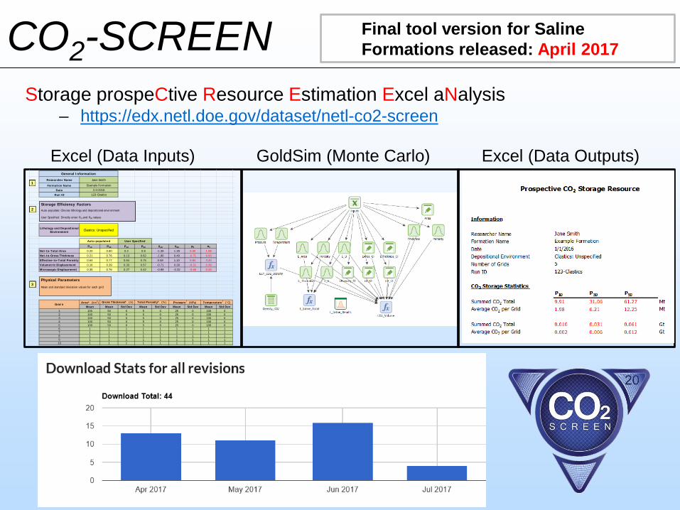
Storage prospeCtive Resource Estimation Excel aNalysis– https://edx.netl.doe.gov/dataset/netl-co2-screen
CO2-SCREEN
Excel (Data Inputs) GoldSim (Monte Carlo) Excel (Data Outputs)Researcher Name
Formation NameDate
Run ID
Lithology and Depositional Environment
P10 P90 P10 P90 X10 X90 μX σX
Net-to-Total Area 0.20 0.80 0.2 0.8 -1.39 1.39 0.00 1.08Net-to-Gross Thickness 0.21 0.76 0.13 0.62 -1.90 0.49 -0.71 0.93Effective-to-Total Porosity 0.64 0.77 0.64 0.75 0.58 1.10 0.84 0.20Volumetric Displacement 0.16 0.39 0.33 0.57 -0.71 0.28 -0.21 0.39Microscopic Displacement 0.35 0.76 0.27 0.42 -0.99 -0.32 -0.66 0.26
Area* (km2)Mean Mean Std Dev Mean Std Dev Mean Std Dev Mean Std Dev
1 100 50 0 5 0 25 0 100 02 100 50 0 5 0 25 0 100 03 100 50 0 5 0 25 0 100 04 100 50 0 5 0 25 0 100 05 100 50 0 5 0 25 0 100 06 1 1 1 1 1 1 1 1 17 1 1 1 1 1 1 1 1 18 1 1 1 1 1 1 1 1 19 1 1 1 1 1 1 1 1 110 1 1 1 1 1 1 1 1 111 1 1 1 1 1 1 1 1 1
Auto-populated User Specified
Clastics: Unspecified
Example Formation1/1/2016
Jane Smith
123-Clastics
General Information
Grid #
Gross Thickness* (m) Total Porosity* (%) Pressure† (MPa) Temperature† (°C)
Physical ParametersMean and standard deviation values for each grid
Storage Efficiency FactorsAuto-populate: Choose lithology and depositional environment
User Specified: Directly enter P10 and P90 values
3
2
Storage Efficiency FactorsAuto-populate: Choose lithology and depositional environment
User Specified: Directly enter P10 and P90 values
1
Final tool version for Saline Formations released: April 2017

21
CO2-SCREEN
• Oriskany Formation (PA only)• Well log data set (5744 wells)
• Depth, thickness, porosity, temperature, pressure
Lithology: ClasticsDepositional Environment: Shallow Shelf
Pennsylvania OriskanyCO2 Storage Resource
CO2-SCREEN Results:P10 = 0.07 GtP90 = 1.28 Gt
Popova et al., (2014) Results:• P10 = 0.15 Gt• P90 = 1.01 Gt
Saline Formation Example

22
𝐺𝐺𝐶𝐶𝐶𝐶2 = 𝐴𝐴ℎ𝑛𝑛𝜙𝜙𝑒𝑒 1 − 𝑆𝑆𝑤𝑤𝑤𝑤 𝐵𝐵𝜌𝜌𝐶𝐶𝐶𝐶2𝑠𝑠𝑡𝑡𝑠𝑠𝐸𝐸𝑠𝑠𝑤𝑤𝑜𝑜/𝑔𝑔𝑔𝑔𝑠𝑠User Inputs
GCO2 Empirical, (Mt)
GCO2 Koval-Claridge, (Mt)
GCO2 Gravity Assisted, (Mt)
Formation Height, h (m) Area, A (km2)
Porosity, ρ (%)Water
Saturation, Swi(%)
Gravity API
Vazquez-Beggs Correlation
Volumetric Ratio, Boi
(Vreservoir/Vsurface)
Efficiency Factor [Empirical, Koval-Claridge, Gravity
Assited]
A = the area of the structurehn = the net thickness ϕe = the effective porosity of the formationB = the fluid formation volume factor that converts standard oil and gas volume to subsurface volume Swi = the initial water saturation in the formationρCO2std = the standard density of CO2Eoil/gas = the efficiency coefficient
Enhanced Oil Recovery CO2-SCREEN

CO2 Prophet Model and CO2-SCREEN
• CO2 stored via CO2 EOR with water chase is comparable to CO2 stored via saline storage with a domal structure
• CO2 storage is lowest for saline storage with flat structure
• If CO2 EOR with CO2 chase or almost pure CO2flood is used, CO2 storage with CO2 EOR is greater
• If ROZ is produced as well as main pay zone, then CO2 storage is greater with CO2 EOR
• Conceptually, CO2 EOR should have the highest CO2 storage and CO2 storage coefficients
– CO2 EOR removes oil and water and replaces with CO2
– CO2 saline storage must displace water to store CO2
23
NetPay
GrossPay
Oil Bearing Formation
Gas Cap
Oil Zone
Residual Oil Zone
Water/ Brine
Forma-tionThick-ness
Impermeable Layer
Impermeable Layer
Oil and GasZone
Comparison of CO2 Storage Factors from CO2 Enhanced Oil Recovery Using the FE/NETL CO2 Prophet Model and from Saline Storage Using NETL’s CO2-SCREEN Model
CO2-SCREEN
24
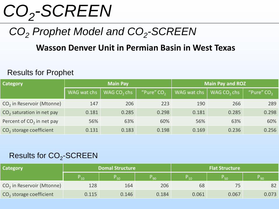
Results for Prophet
Results for CO2-SCREEN
Category Main Pay Main Pay and ROZ
WAG wat chs WAG CO2 chs “Pure” CO2 WAG wat chs WAG CO2 chs “Pure” CO2
CO2 in Reservoir (Mtonne) 147 206 223 190 266 289
CO2 saturation in net pay 0.181 0.285 0.298 0.181 0.285 0.298
Percent of CO2 in net pay 56% 63% 60% 56% 63% 60%
CO2 storage coefficient 0.131 0.183 0.198 0.169 0.236 0.256
Category Domal Structure Flat Structure
P10 P50 P90 P10 P50 P90
CO2 in Reservoir (Mtonne) 128 164 206 68 75 82
CO2 storage coefficient 0.115 0.146 0.184 0.061 0.067 0.073
Wasson Denver Unit in Permian Basin in West Texas
CO2 Prophet Model and CO2-SCREEN
CO2-SCREEN

DEVELOP DEFENSIBLE DOE METHODOLOGY FOR REGIONAL ASSESSMENTSUnconventional Systems• Team Members: Sean Sanguinito, Eugene Myshakin, Harpeet Singh, Grant Bromhal, and Angela GoodmanResidual Oil Zones (ROZs)• Team Members: Tom McGuire, Tim Grant, Dave Morgan, Bob Dilmore, Angela GoodmanOffshore• Team Members: Kelly Rose , Emily Cameron, Burt Thomas, Jen Bauer, Andrew Bean, Jenny DeGiulio, Roy
Miller, Lucy Romeo, Mike Sabbatino
EXPAND METHODOLOGY TO INCLUDE STOCHASTIC APPROACH FOR KEYPARAMETERS
– Saline Systems , Oil Reservoirs, Shale Formations/ CO2 SCREEN• Team Members: Sean Sanguinito, Jim Sams, Maggie Martin, and Angela Goodman
EXPAND METHODOLOGY TO INCLUDE GEOSPATIALLY VARIABLE KEY PARAMETERS– Saline Systems - SIMPA
• Team Members: Jennifer Bauer, Devin Justman, Katherine Jones, Patrick Wingo, Kelly Rose, Gabe Creason, Veronika Vasylkivska, Jake Nelson 25
Presentation OutlineResource Assessment
Met
hods
Tools

SIMPA
Produce a product that helps decision makers evaluate cumulative spatial trends and identify knowledge gaps
The spatially integrated multi-scale probabilistic assessment (SIMPA) spatial analysis framework will support evaluation of potential risks and impacts CO2 storage might pose
to various human health and environmental factors to help guide decision making and risk management pertaining to the develop and use of various carbon capture and storage methods
Using in situ Knowledge and Data to Identify the Probability of Subsurface Fluid Migration
Developing a framework (data & tools) to assess multiple spatial attributes related to:
• Seek to identify areas within an user specific area that have a higher probability of connectivity to fluid flow pathways
• Calculating the probability at meso- to regional scales
Storage Volume & Distribution(spatial trends, XYZ)

27
Developing Input Data for SIMPA Model
Testing and validation of wellborematerials and pathways data• Identify optimal data
attributes and support development of membership functions
Data from IHS Enerdeq database534,965 wells
Number of Redrills
Freq. of Wells per Completion YearWell Depth per Completion Year
SIMPA

Developing Input Data for SIMPA ModelSIMPA
Finalize data and approach for assessing structural complexity
Surface
Basement

Developing SIMPA FrameworkSIMPA
Evaluate, select, and develop data-driven, machine learning framework for SIMPA model, leveraging wellbore and structural data as inputs
Various machine learning (ML) methods were assessed; Fuzzy Logic selected because it:
• Handles highly complex, real world data and uncertainty
• Works with numerical and categorical data inputs
• Can readily couple with other ML approaches and spatial data
• Supervised, Natural language processing helps make the workflow more intuitive
• Uses “If – Then” statements
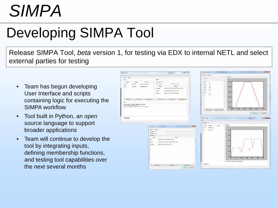
Developing SIMPA ToolSIMPA
Release SIMPA Tool, beta version 1, for testing via EDX to internal NETL and select external parties for testing
• Team has begun developing User Interface and scripts containing logic for executing the SIMPA workflow
• Tool built in Python, an open source language to support broader applications
• Team will continue to develop the tool by integrating inputs, defining membership functions, and testing tool capabilities over the next several months

Accomplishments to DateProject Summary
31
DEVELOP DEFENSIBLE DOE METHODOLOGY FOR REGIONAL ASSESSMENTSUnconventional Systems• Storage efficiencies developed for prospective CO2 storage resource of shales• Development of CO2-SCREEN for shaleResidual Oil Zones (ROZs)• Identify key aspects of CO2 storage in a ROZ and develop a draft method for prospective
storage of CO2 in ROZs Offshore• Started a database of saline reservoir properties for GOM Including porosity, net, gross and
other saline reservoir properties• Update storage efficiencies
EXPAND METHODOLOGY TO INCLUDE STOCHASTIC APPROACH FOR KEY PARAMETERS- CO2 SCREEN• Released CO2-SCREEN to the public. Applying to saline formations and EOR • Develop SCREEN for shale, EOR, and ROZs
EXPAND METHODOLOGY TO INCLUDE GEOSPATIALLY VARIABLE KEY PARAMETERS -SIMPA• Testing and validation of wellbore materials/pathways data and structural complexity• Release SIMPA model, version 1 through EDX
Met
hods
Tools

Synergy Opportunities
32
• CO2 storage methodology development and refinement manuscripts undergo review by the Regional Carbon Sequestration Partnerships (RCSP’s), field experts, and the peer-review process prior to publication
• Incorporation of Experimental and Modeling parameters need to refine and improve storage efficiency factors – Offshore/Saline/Shale
• SIMPA: • Wellbore pathways: Developing &
incorporating information on probability of wellbore occurrence, proximity and leakage potential Ties to NRAP
• Structural pathways: Incorporating information related to the probability of existing structural complexity for a given domain/area (e.g., faults, folds) Ties to SubTER Induced seismicity project

Lessons Learned– Research gaps/challenges.– Unanticipated research difficulties.– Technical disappointments.– Changes that should be made next time.– Multiple slides can be used if needed.
33

Appendix– These slides will not be discussed during the presentation, but
are mandatory.
34

35
Benefit to the Program • Carbon Storage Program Major Goals
– Support industry’s ability to predict CO2storage capacity in geologic formations to within ±30 percent.
• Project Benefits Statement:– This research project aims at developing and
maintaining tools/resources that facilitate assessment of prospective CO2 storage at the national, regional, basin, and formation scale

36
Project Overview: Goals and Objectives
• Carbon Storage Program Major Goals:– Support industry’s ability to predict CO2 storage capacity in
geologic formations to within ±30 percent. • Project Benefits Statement:
– This research project aims at developing and maintaining tools/resources that facilitate regional- and national-scale assessment of carbon storage
• Project Objectives:– Resource Assessments: Develop a Defensible DOE
Methodology for Regional Assessments• Develop, refine, and evaluate a suite of
methodologies/methods to quantitatively assess CO2 storage resource potential in onshore and offshore reservoirsincluding saline formations, oil and gas reservoirs, coal seams, and shales.
37
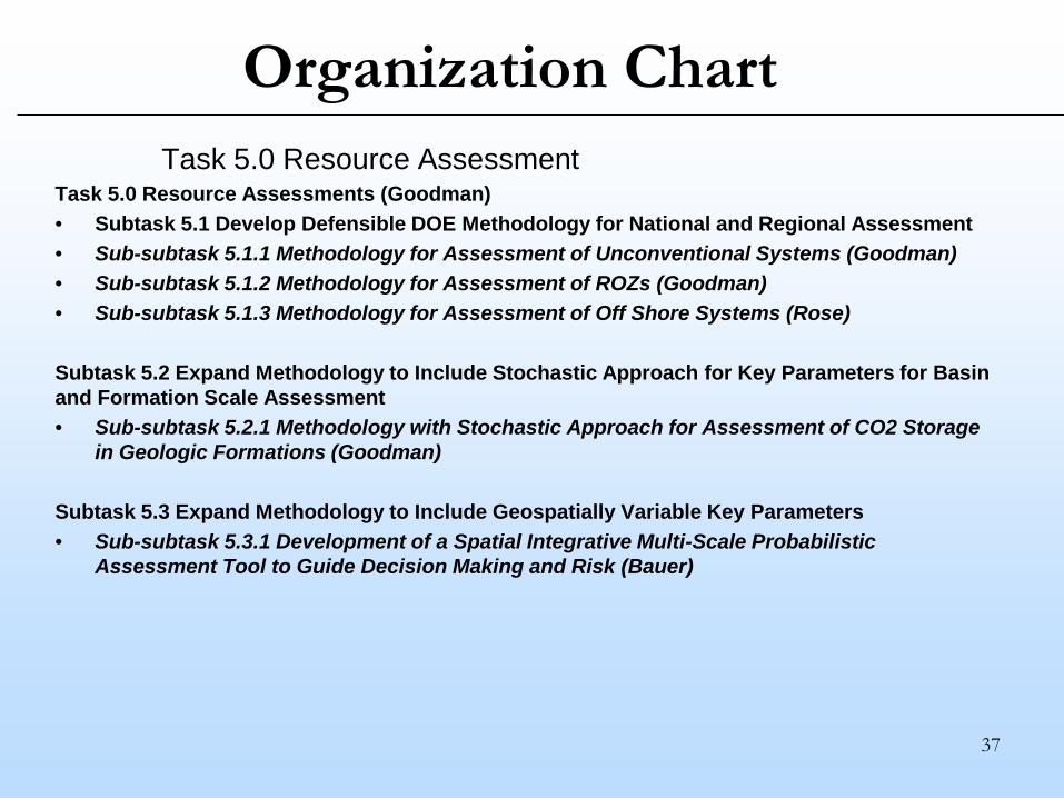
Organization ChartTask 5.0 Resource Assessment
Task 5.0 Resource Assessments (Goodman)• Subtask 5.1 Develop Defensible DOE Methodology for National and Regional Assessment• Sub-subtask 5.1.1 Methodology for Assessment of Unconventional Systems (Goodman)• Sub-subtask 5.1.2 Methodology for Assessment of ROZs (Goodman)• Sub-subtask 5.1.3 Methodology for Assessment of Off Shore Systems (Rose)
Subtask 5.2 Expand Methodology to Include Stochastic Approach for Key Parameters for Basin and Formation Scale Assessment• Sub-subtask 5.2.1 Methodology with Stochastic Approach for Assessment of CO2 Storage
in Geologic Formations (Goodman)
Subtask 5.3 Expand Methodology to Include Geospatially Variable Key Parameters• Sub-subtask 5.3.1 Development of a Spatial Integrative Multi-Scale Probabilistic
Assessment Tool to Guide Decision Making and Risk (Bauer)

38
Gantt ChartTask 5.0 Resource Assessments
Develop Defensible DOE Methodology for National and Regional Assessment
Milestone – Complete modeling and simulation efforts to estimate storage efficiency factors needed to estimate prospective CO2 storage in shale.
Milestone – Develop beta CO2-SCREEN Tool for shale for public assess on EDX.
Milestone – Conduct a joint meeting with the SE&A Team to coordinate and communicate work and progress on ROZ research.
Milestone – Identify key aspects of CO2 storage in a ROZ and develop a draft method for prospective storage of CO2 in ROZs while including input and collaboration from additional stakeholder discussions with ROZ experts, including RCSP.
Milestone – Develop framework and approach for incorporating tools/models from the Offshore Risk Model into the Offshore carbon storage methodology to address prospectivity/storage feasibility steps for the storage assessment.
Milestone – Develop approach for developing GoM specific efficiency factors custom using BOEM open source reservoir data.
Milestone – Complete draft development/calculation of GoM efficiency factors.
Milestone – Complete evaluation of options for developing an unconventional, offshore assessment approach.
1/10/2017 – 12/31/2017
Q1 Q2 Q3 Q4

39
Gantt Chart
Milestone – Demonstrate in GoM integrated DOE storage assessment approach with GoM tailored efficiency factors and Offshore risk tools for enhanced offshore carbon storage and feasibility assessment.
5.2 Expand Methodology to Include Stochastic Approach for Key Parameters for Basin and Formation Scale Assessment
Milestone – Expand methodology to include stochastic approach for key parameters for basin and formation scale assessment for saline formations. This includes having the method ready for inclusion of the future Carbon Storage Atlas and as a peer-reviewed journal article.
M1 Milestone (M1.17.5.A) – Complete development and review of a screening tool for CO2 storage in saline formation. This will incorporate comments and suggestions of CO2-SCREEN by users such as KeyLogic, Battelle, and the SW Partnership.
Milestone – Develop new beta CO2-SCREEN Tools for conventional (oil reservoirs) and unconventional (depleted shale) systems.
5.3 Expand Methodology to Include Geospatially Variable Key Parameters
Milestone – Summarize key results of testing and validation of wellbore materials/pathways input data for use in the SIMPA framework in quarterly report.
M1 Milestone (M1.17.5.B) – SIMPA Tool (version 1) available for internal and selected external testing on an EDX collaborative workspace.
Milestone – Develop draft report or manuscript detailing spatial approach for assessing structural complexity.
Milestone – Develop a draft user manual (in a presentation or report) for the SIMPA tool that provides information on the tool and a couple example products.

Bibliography
40
Publications
1. Sanguinito, S.; Goodman, A. L.; Levine, J. S. NETL CO2 Storage prospeCtive Resource Estimation Excel aNalysis (CO2-SCREEN) User’s Manual; NETL-TRS-6-2017; NETL Technical Report Series; U.S. Department of Energy, National Energy Technology Laboratory: Pittsburgh, PA, 2017; p 28.
2. Tudek, J.; Crandall, D.; Fuchs, S.; Werth, C. J.; Valocchi, A. J.; Chen, Y.; Goodman, A. In situ contact angle measurements of liquid CO2, brine, and Mount Simon sandstone core using micro X-ray CT imaging, sessile drop, and Lattice Boltzmann modeling. Journal of Petroleum Science and Engineering in press 2017.
3. Glosser, D.; Bauer, J. R. A Graph Theoretic Approach for Spatial Analysis of Induced Fracture Networks. Journal of Sustainable Energy Engineering 2016, 4, 232–249.
4. Glosser, D.; Rose, K.; Bauer, J. R. Spatio-Temporal Analysis to Constrain Uncertainty in Wellbore Datasets: An Adaptable Analytical Approach in Support of Science-Based Decision Making. Journal of Sustainable Energy Engineering 2016, 3, 299–317.
5. Goodman, A.; Sanguinito, S.; Levine, J. Prospective CO2 Saline Resource Estimation Methodology: Refinement of Existing DOE-NETL Methods Based on Data Availability. International Journal of Greenhouse Gas Control 2016, 54, 242–249.
Presentations1. “DOE Screening Methodology for Estimating the Prospective CO2 Storage Resource of Shales and Identifying Data Gaps” Joint 52nd Northeastern Annual
Section / 51st North-Central Annual Section Meeting - Pittsburgh, Pennsylvania March 18-22, 20172. “Resource Assessment Methods for CO2 Storage in Geologic Formations” Mastering the Subsurface Through Technology, Innovation and Collaboration:
Carbon Storage and Oil and Natural Gas Technologies Review Meeting, Pittsburgh, Pennsylvania August 16-18, 2016 3. “NETL’s Research & Innovation Center Carbon Storage Portfolio” GSCO2 Annual Meeting Champaign, IL March 30-31, 2016


