Chesterfield Economic Development - 2014 - A look back. A peek forward.

00 David Taylor Research Center(.0 Bethesda, MD 20084-5000Cq_ _ _ _ _ _
~~ DTRC-SME-90/28 August 1990DTC LLGYShip Materials Engineering DepartmentResearch & Development Report
E
Method for Evaluating the High Strain-Rate%E Compressive Properties of Thick Composite
Laminates
by~ D.M. Montiel
C.J. Williams
OTICSELECTEAUG30US35
Approved tor public release; distribution Is unlimited.
0i19o -JA2P
CODE 011 DIRECTOR OF TECHNOLOGY, PLANS AND ASSESSMENT
12 SHIP SYSTEMS INTEGRATION DEPARTMENT
14 SHIP ELECTROMAGNETIC SIGNATURES DEPARTMENT
15 SHIP HYDROMECHANICS DEPARTMENT
16 AVIATION DEPARTMENT
17 SHIP STRUCTURES AND PROTECTION DEPARTMENT
18 COMPUTATION, MATHEMATICS & LOGISTICS DEPARTMENT
19 SHIP ACOUSTICS DEPARTMENT
27 PROPULSION AND AUXILIARY SYSTEMS DEPARTMENT
28 SHIP MATERIALS ENGINEERING DEPARTMENT
DTRC ISSUES THREE TYPES OF REPORTS:
1, DTRC reports, a formal series, contain Information of permanent technical value.They carry a consecutive numerical Identification regardless of their classification or theoriginating department,
2. Departmental reports, a semiformal series, contain Information of a preliminary,temporary, or proprietary nature or of limited interest or significance. They carry adepartmental alphanumerical Identification.
3, Technical memoranda, an Informal series, contain technical documentation oflimited use and interest. They are primarily working papers intended for internal use, Theycarry an identifying number which Indicates their type and the numerical code of theoriginating department. Any distribution outside DTRC must be approved by the head ofthe originating department on a case-by-case basis,
NOW -JTN.RHUC 5602 ,51 (Hav 2.88)

UnclassifiedfremULTY CLASSIFICArION OF THIS PACjE
REPORT DOCUMENTATION PAGE
UNCLASSIFIEDI.REPORT 6EUIYCASFCTO1l.RSRCIEMRIG
.. SECURITy CLASSIRUCATIN AUTH4ORITY I OI1TRISUTIONlAVAILMIUTy OF REPORTApproved for Public Release;
2 b. DECLASIFICTIIO91 NGRADING SCHEDULE distribution unlimited
4, PERFORMING ORGANIZA"TION REPORT NUMBER4S) S, MONITORING ORGANIZATION REPORT NUMIER(S)
*DTRC/SME-90-28
UNAEOFPERFORMINGFWANATION G OFICE SYMIOL ft. NAME OF MONITORING ORGANIZATIONDavid Taylor ( pkResearch Center .2814
6c. ADDRESS (City. State. And VPCCOW 7b. AoDDRESS (city, ste ft. and ZIP Code)
Bethesda, MD 20084-5000
go, NAME OF FUNDING ISPONSORING 8b. OfFFIC SYMBOL. 9. MPROURMENT INSTRUMENT IDENTIFICATION NUM11ERORGANIZATION (N ,.
DTRC 0113ADDRSS (ity.Ram nd 10*)10, SOURCE OF FUNDINGO NUM9ERS
PROGR01PRJECT TASK I WOR UNITEMNT o. NO, INO. IACCESSION #40.
61 rl5152PN I1000-01-01 1DN507048
It ITLE (Inch&e S#CW* IS90OhWidtiI (U) METHOD FOR EVALUATING THE-HIGH STRAIN RATE COMPRESSIVE
PROPERTIES OF THICK COMPOSITE LAMINATES
12 FAONA AT141..1D.M. Montiel and C.J. Williams
136. TYPERQFDREPORT 13b. TIME MOERE 4.DT Of REORT (*St. Mwot. DoyI 1. PAGE COUNTtoi PROM Mv om TO 10/go Mac a99 20
IS SUPPLEMENTARY NOTATION
Presented at ASTM 10th Symposium on Composite Materials: Testing & Design
17 COSATI CODES J19ý,SUIIJECT TERMS(C0MMue-nwwvefm i lw0~
FIELD GROUP SUS.GROUP Composites, Carbon/Peek, Thick;Section Laminates,Strain Rate, Compression, Reinforced Plastics ~~
19 AUSTRAC . oninue on reverm If =euarv and identify 6v Maock numberlA test apparatus .and methodology developed to obtain high strain-rate compressive
mechanical properties of various fiber-reinforced composite materials is described.
This direct compression method utilized a drop tower to impart a load at dynamic rates
to the test fixture. Uniform specimen loading was accomplished through the use of
aligned guide rails to constrain all but the vertical motion of a fVee-sliding
impactor. Specimen endoaps-, specific to thick-section testing, were implemented to
prevent premature brooming filure. A piezoelectric transducer and aluminum absorbers
were some of the refinements \introduced to alloy acquim ition of stress and strain data
free of distortion. Strain r tea on the order of 8 sec have been achieved, and
higher rates appear possible, Material property data was obtained on a series of AS4
graphite/PEEK thermoplastic 0 290 composite laminates. The results of the first study
Indicated that at high strain rate loading, the strength of this material increased 42
percent over static values and the strain to failure increased by 25 percent, whereas
the elastic modulus remained unaffected.
20 LDiSI R1UTION1IAVAILABILITY O07 AB$S-TRACT 21 ABSTRACT SECuRITY CLASSIFICATION
OlUNCLASSINIEOIUNLIMITEO 9 SAME AS RP QIOTIC USERS tm7AT~n
feNAME OF RESPONSIBLE INDIVIDUAL 22b TELEPHONE (include Area Code) 22( OFFICE SYMNOL.Denise M. Montiel (301) 267-4986 ICode 2814
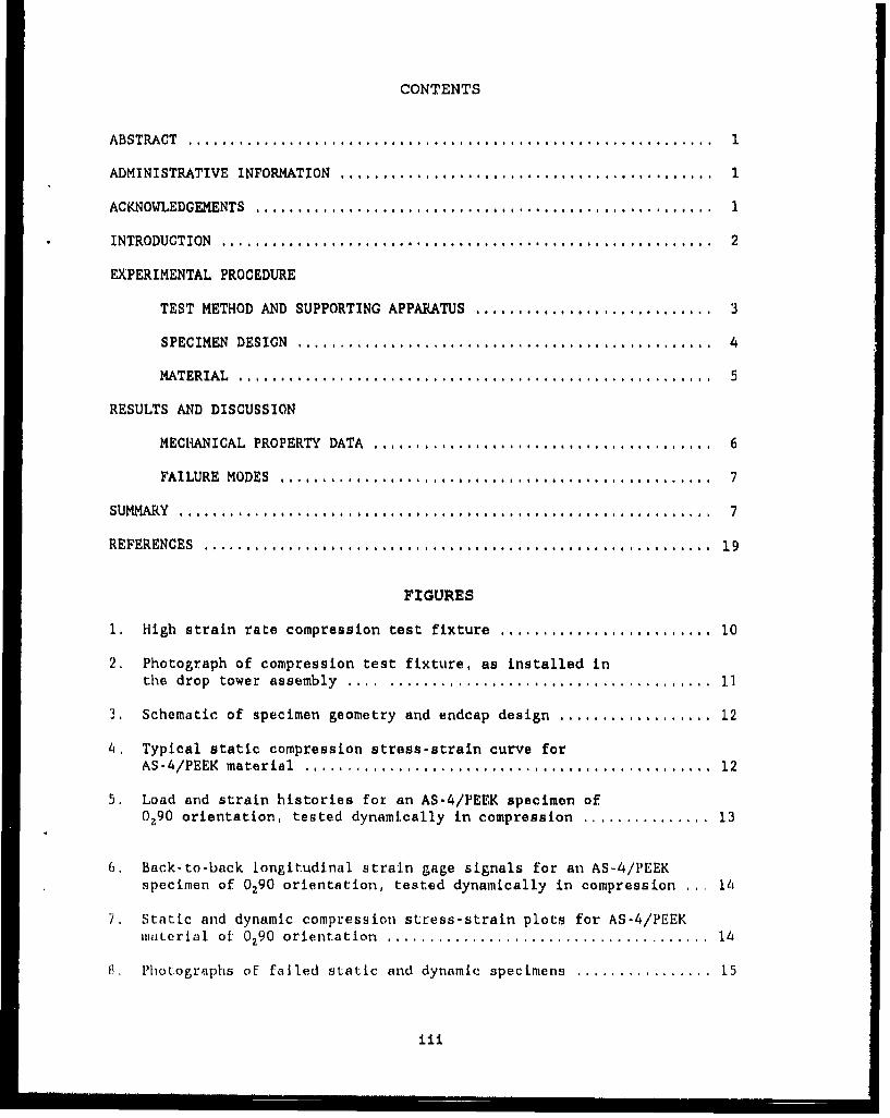
CONTENTS
ABSTRA CT .............................................................. 1
ADMINISTRATIVE INFORMATION ............................................ 1
ACKNOWLEDGEMENTS ...................................................... 1
INTRODUCTION .......................................................... 2
EXPERIMENTAL PROCEDURE
TEST METHOD AND SUPPORTING APPARATUS ............................ 3
SPECIMEN DESIGN ................................................. 4
MATERIAL ........................................................ 5
RESULTS AND DISCUSSION
MECHANICAL PROPERTY DATA ........................................ 6
FAILURE HODES ................................................... 7
SUMMARY ..................................................... .......... 7
REFERENCES ............................................................ 19
FIGURES
1. High strain rate compression test fixture ......................... 10
2. Photograph of compression test fixture, as installed inthe drop tower assembly ..... ...................................... 11
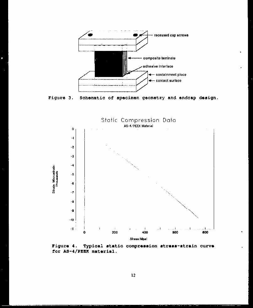
3. Schematic of specimen geometry and endcap design .................. 12
4, Typical static compression stress-strain curve forAS-4/PEEK material ................................................ 12
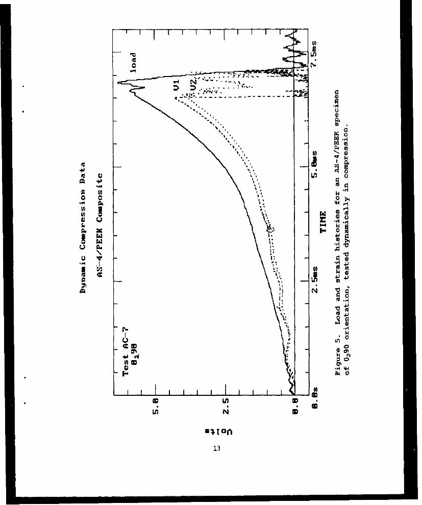
5. Load and strain histories for an AS-4/PEEK specimen of0.90 orientation, tested dynamically in compression ............... 13
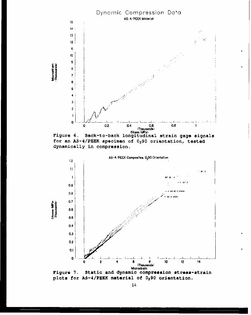
6, Back-to-back longitudinal strain gage signals for an AS-4/PEEKspecimen of 0290 orientation, tested dynamically in compression ... 14
7. Static and dynamic compression stress-strain plots for AS-4/PEEKmaLerial ot 0290 orientation ...................................... 14
8, Photographs of failed static and dynamic specimens ................ 15
liii

9. Micrographs showing delamination patterns of outer plies in staticand dynamic compression specimens ................................. 16
10, Kicrographs of crush zone regions in static and dynamiccompression specimens ............................................ 17
TABLES
1. Static compression test data for AS-4/PEEK material(0290 orientation) ................................................ 9
2. High strain rate test data for AS-4/PEEK material(0290 orientation) ................................................ 9
ocoession For
NTIS GRA&IDTIC TAB Q3uUmeulowleed -Justirinat~ioe 0
By
Availability Codea
JAvail and/.rDist j Speoial
Iv
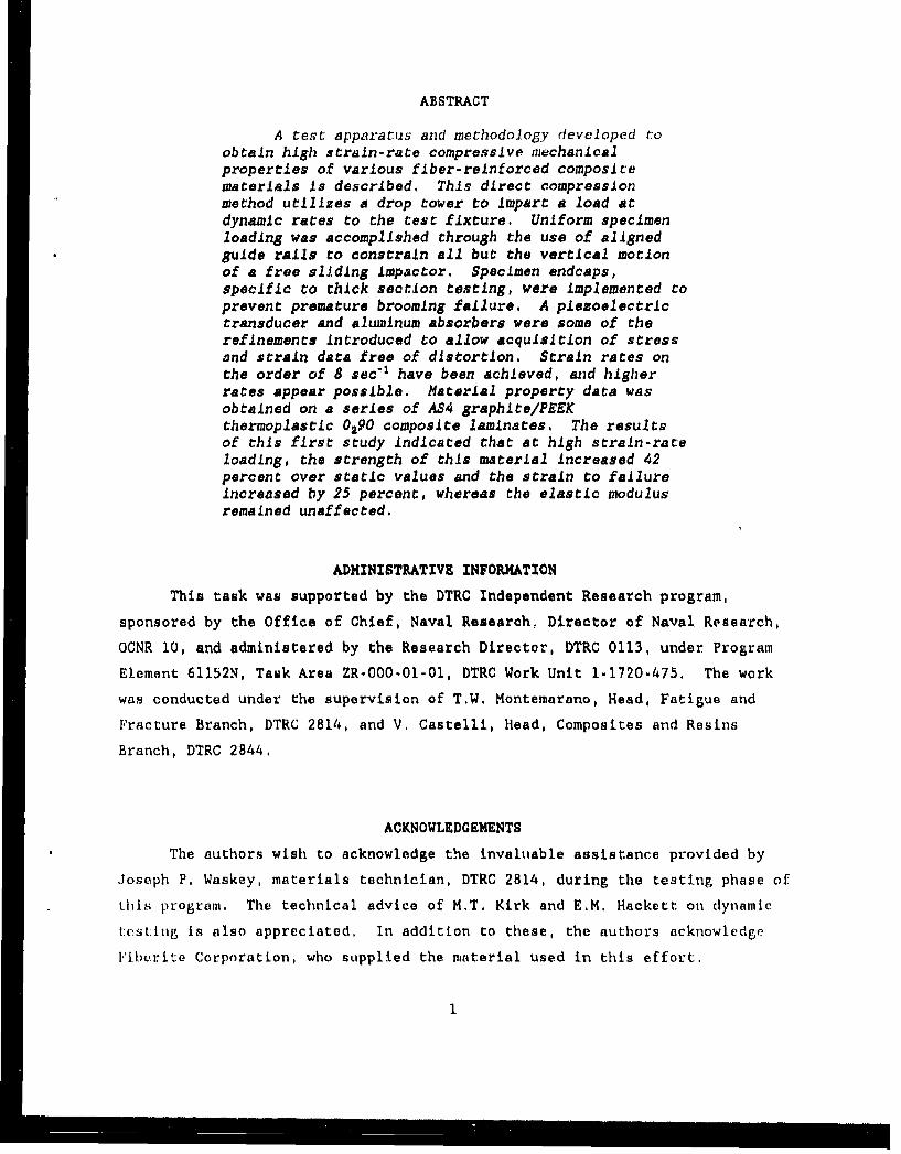
ABSTRACT
A test apparatus and methodology developed toobtain high strain-rate compressive mechanicalproperties of various fiber-reinforced compositematerials is described, This direct compressionmethod utilizes a drop tower to impart a load atdynamic rates to the test fixture. Uniform specimenloading was accomplished through the use of alignedguide rails to constrain all but the vertical motionof a free sliding Impactor. Specimen endcaps,specific to thick section testing, were implemented toprevent premature brooming failure. A piezoelectrictransducer and aluminum absorbers were some of therefinements introduced to allow acquisition of stressand strain data free of distortion. Strain rates onthe order of 8 sec1I have been achieved, and higherrates appear possible. Material property data wasobtained on a series of AS4 graphite/PEEKthermoplastic 0290 composite laminates. The resultsof this first study indicated that at high strain-rateloading, the strength of this material increased 42percent over static values and the strain to failureincreased by 25 percent, whereas the elastic modulusremained unaffected.
ADMINISTRATIVE INFORMATION
This task was supported by the DTRC Independent Research program,
sponsored by the Office of Chief, Naval Research, Director of Naval Research,
OCNR 10, and administered by the Research Director, DTRC 0113, under Program
Element 61152N, Task Area ZR-O00.0l-01, DTRC Work Unit 1-1720-475. The work
was conducted under the supervision of T.W. Montemarano, Head, Fatigue and
Fracture Branch, DTRC 2814, and V. Castelli, Head, Composites and Resins
Branch, DTRC 2844.
ACKNOWLEDGEMENTS
The authors wish to acknowledge the invaluable assistance provided by
Joseph P. Waskey, materials technician, DTRC 2814, during the testing phase of
this program, The technical advice of H.T. Kirk and E.MX Hackett on dynamic
t:esting is also appreciated. In addition to these, the authors acknowledge
Iil,.)rite Corporation, who supplied the material used in this effort.
1

INTRODUCTION
Fiber-reinforced nonmetallic composites have shown great promise as high
strength structural materials for naval applications, due to the potential
benefits of decreased weight and increased stiffness. However, the future of
advanced composite systems for most naval structures depends on an in-depth
understanding of how these materials behave under high-rate loading
conditions. There currently exists only a limited body of knowledge of t!,
properties and failure behavior of these materials at high strain-rates t.o
support dependable design for naval applications. One such case is modelling
the response of composite cylinders to shock loading. Analytical methods have
been used to simulate the structural response of a composite cylinder during a
dynamic shock event. However, for these models to be accurate, realistic high
strain-rate material property input is needed in the analysis, Quasi-static
data may not be adequate for design analysis, since it has been shown that
modulus, strength, strain-to-failure and failure modes of composites can vary
significantly with strain rate , Unfortunately, the high strain-rate
behavior of the thick section composites utilized in this application is a
relatively unexplored area. Dynamic testing of these materials by any loading
mode has been very limited, and the results found in the available literature
are inconsistent due to limited test techniques and specialized specimen
geometries, This lack of accurate high strain-rate material property data for
thick section composites has impeded the utilization of these materials in the
Navy. The work described in this report was initiated to develop the
experimental techniques required to assess the high strain-rate compressive
properties of thick section composite material systems. Specifically, a test
methodology ior high strain-rate compression testing of end-loaded thick
section composite laminate coupons has been developed.
The quantitative definition of strain-rate ranges is generally arbitrary,
since the range is usually defined by the material response. In using the
term "high strain rate" we have followed the guidance of Rotem and
Lifshitz( 31, who categorized the high strain.rate regime for composites as
being in the range of 5 - 30 sec-.
2

EXPERIMENTAL PROCEDURE
Test Method and Supoortin_ ARparatus
Earlier in-house investigations indicated that the compression test
fixtures used for quasi-static testing of thick section laminates could not be
readily adapted for testing under a dynamic loading. The first phase of this
work, then, was to design a new compression apparatus to dynamically impact an
end-loaded coupon, where load was introduced by direct bearing on the end of a
short, rectangular specimen of appreciable thickness (greater than 2,54mm
thick) and unsupported gage length. The new apparatus is pictured in Figure
1. The fixture consisted of a tee-shaped impactor that was aligned and
directed by two vertical guide rails, one on each side, The rails were bolted
into a channel contained in a steel base perpendicular to the rails, which
aligned the rails both perpendicularly to the base and laterally with one
another, The lateral distance of separation between the rails was adjustable
to accomodate free sliding of the impactor, The impactor was machined from
AISI 4340 steel, hardened to 44 HRC. A hardened 4340 steel bottom plate was
seated between the rails to provide a flat surface, parallel to the impactor
bottom face, on which to place the specimen. Close tolerances were specified
for flatness and perpendicularity on the contact faces to minimize specimen
out-of-plane loading.
A drop tower assembly was used to achieve a loading duration within an
order of magnitude of that achieved during the explosion tear test, which has
been designed to be characteristic of the loading response of a metallic
structure to dynamic loadingC]. The free-falling crosshead of the drop
tower, guided by the drop tower load frame, was used to impart load to the
test fixture, The test fixture is shown installed in the drop tower in Figure
2, The falling drop tower crosshead tup directly contacted the top of the
fixture impactor; a vertical stud on top of the impactor was threaded to
accomodate a piezoelectric load cell, which transmitted the load signal. A
small, pyramidal absorber made of 6061-0 aluminum (fully annealed condition)
was positioned between the load cell and the drop tower tup. The function of
this absorber was to damp out the spurious noise in the load and strain
histories due to apparatus vibrations and steel-on-steel contact, where the
3
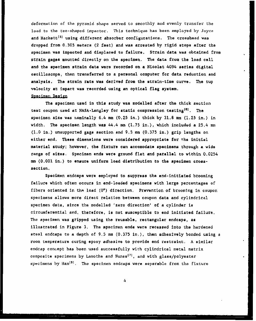
deformation of the pyramid shape served to smoothly and evenly transfer the
load to the tee-shaped impactor. This technique has been employed by Joyce
and Hackett"I using different absorber configurations. The crosshead was
dropped from 0.305 meters (2 feet) and was arrested by rigid stops after the
specimen was impacted and displaced to failure. Strain data was obtained from
strain gages mounted directly on the specimen. The data from the load cell
and the specimen strain data were recorded on a Nicolet 4094 series digital
oscilloscope, then transferred to a personal computer for data reduction and
analysis. The strain rate was derived from the strain-time curve. The tup
velocity at impact was recorded using an optical flag system.
Specimen Design
The specimen used in this study was modelled after the thick section
test coupon used at NASA-Langley for static compression testingto). The
specimen size was nominally 6.4 mm (0.25 in.) thick by 31.8 mm (1.25 in.) in
width, The specimen length was 44.4 mm (1.75 in.), which included a 25,4 mm
(1.0 in.) unsupported gage section and 9.5 mm (0.375 in.) grip lengths on
either end, These dimensions were considered appropriate for the initial
material study, however, the fixture can accomodate specimens through a wide
range of sizes. Specimen ends were ground flat and parallel to within 0.0254
mm (0,001 in,) to ensure uniform load distribution to the specimen cross-
section.
Specimen endcaps were employed to suppress the end-initiated brooming
failure which often occurs in end-loaded specimens with large percentages of
fibers oriented in thA load (00) direction, Prevention of brooming in coupon
specimens allows more direct relation between coupon data and cylindrical
specimen data, since the modelled 'zero direction' of a cylinder is
circumferential arid, therefore, is not susceptible to end initiated failure,
The specimen was gripped using the reusable, rectangular endcaps, as
illustrated in Figure 3. The specimen ends were recessed into the hardened
steel endcaps to a depth of 9.5 mm (0.375 in,), then adhesively bonded using a
room temperature curing epoxy adhesive to provide end restraint, A similar
endcap concept has been used successfully with cylindrical metal matrix
composite specimens by Lamothe and Nunes1 y], and with glass/polyester
specimens by Hanl81 . The specimen endcaps were separable from the fixture
4
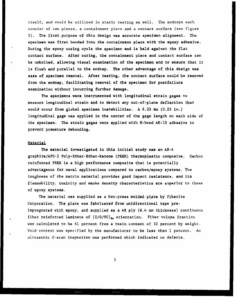
itself, and could be utilized in static testing as well. The endcaps each
consist of two pieces, a containment piece and a contact surface (see figure
3). The first purpose of this design was accurate specimen alignment. The
specimen was first bonded into the containment piece with the epoxy adhesive,
During the epoxy curing cycle the specimen end is held against the flat
contact surface. After curing, the containment piece and contact surface can
be unbolted, allowing visual examination of the specimen end to ensure that it
is flush and parallel to the endcap. The other advantage of this design was
ease of specimen removal, After testing, the contact surface could be removed
from the endcap, facilitating removal of the specimen for postfailure
examination without incurring further damage.
The specimens were instrumented with longitudinal strain gages to
measure longitudinal strain and to detect any out-of-plane deflection that
would occur from global specimen instabilities. A 6.35 mm (0,25 in.)
longitudinal gage was applied in the center of the gage length on each side of
the specimen. The strain gages were applied with M-bond AE-10 adhesive to
prevent premature debonding.
The material investigated in this initial study was an AS-4
graphite/APC-2 Poly-Ether-Ether-Ketone (PEEK) thermoplastic composite, Carbon
reinforced PEEK is a high performance composite that is potentially
advantageous for naval applications compared to carbon/epoxy systems. The
toughness of the matrix material provides good impact resistance, and its
flammability, toxicity and smoke density characteristics are superior to those
of epoxy systems.
The material was supplied as a hot-press molded plate by Fiberite
Corporation, The plate was fabricated from unidirectional tape pre-
impregnated with epoxy, and supplied as a 48 ply (6.4 mm thickness) continuous
fiber reinforced laminate of [0/O/ 90)8, orientation. Fiber volume fraction
was calculated to be 61 percent from a resin content of 32 percent by weight..
Void content was specified by the manufacturer to be less than 1 percent. An
ultrasonic C-scan inspection was performed which indicated no defects.
5
RESULTS AND DISCUSSION
Mechanical Property Data
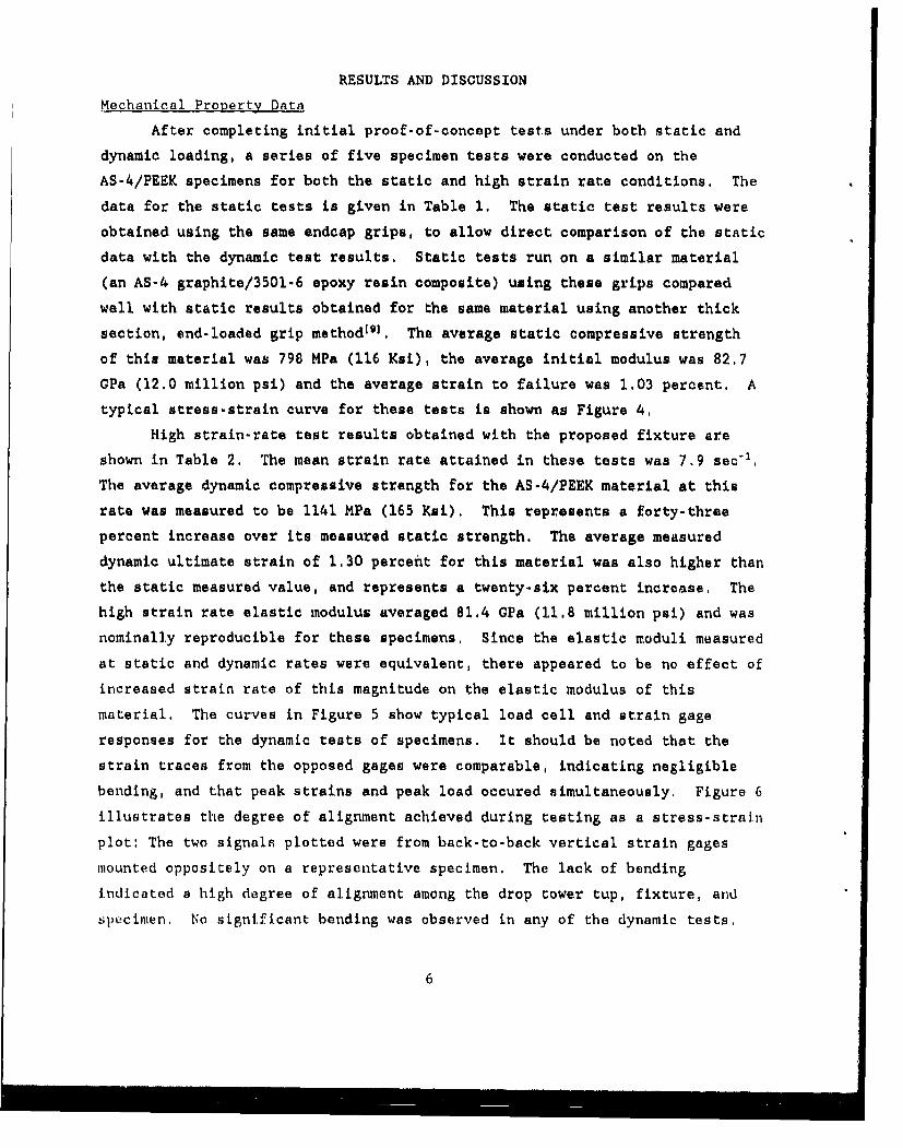
After completing initial proof-of-concept tests under both static and
dynamic loading, a series of five specimen tests were conducted on the
AS-4/PEEK specimens for both the static and high strain rate conditions. The
data for the static tests is given in Table 1. The static test results were
obtained using the same endcap grips, to allow direct comparison of the static
data with the dynamic test results. Static tests run on a similar material
(an AS-4 graphite/3501-6 epoxy resin composite) using these grips compared
well with static results obtained for the same material using another thick
section, end-loaded grip method19 ]. The average static compressive strength
of this material was 798 MPa (116 Ksi), the average initial modulus was 82.7
GPa (12.0 million psi) and the average strain to failure was 1.03 percent. A
typical stress-strain curve for these tests is shown as Figure 4.
High strain-rate test results obtained with the proposed fixture are
shown in Table 2. The mean strain rate attained in these tests was 7.9 sec"1 ,
The average dynamic compressive strength for the AS-4/PEEK material at this
rate was measured to be 1141 MPa (165 Ksi), This represents a forty-three
percent increase over its measured static strength. The average measured
dynamic ultimate strain of 1,30 percent for this material was also higher than
the static measured value, and represents a twenty-six percent increase, The
high strain rate elastic modulus averaged 81.4 GPa (11,8 million psi) and was
nominally reproducible for these specimens, Since the elastic moduli measured
at static and dynamic rates were equivalent, there appeared to be no effect of
increased strain rate of this magnitude on the elastic modulus of this
material. The curves in Figure 5 show typical load cell and strain gage
responses for the dynamic tests of specimens. It should be noted that the
strain traces from the opposed gages were comparable, indicating negligible
bending, and that peak strains and peak load occured simultaneously, Figure 6
illustrates the degree of alignment achieved during testing as a stress-strain
plot: The two signals plotted were from back-to-back vertical strain gages
mounted oppositely on a representative specimen. The lack of bending
indicated a high degree of alignment among the drop tower tup, fixture, and
specimen, No significant bending was observed in any of the dynamic tests.
6
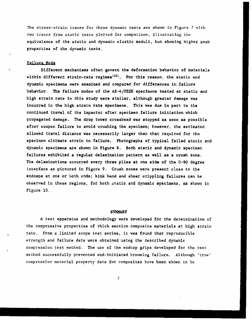
The stress-strain traces for three dynamic tests are shown in Figure 7 with
two traces from static tests plotted for comparison, illustrating the
equivalence of the static and dynamic elastic moduli, but showing higher peak
properties of the dynamic tests.
Different mechanisms often govern the deformation behavior of materials
within different strain-rate regimes°lO). For this reason, the static and
dynamic specimens were examined and compared for differences in failure
behavior, The failure modes of the AS-4/PEEK specimens tested at static and
high strain rate in this study were similar, although greater damage was
incurred in the high strain rate specimens. This was due in part to the
continued travel of the impactor after specimen failure initiation which
propagated damage. The drop tower crosshead was stopped as soon as possible
after coupon failure to avoid crushing the specimen; however, the estimated
allowed travel distance was necessarily larger than that required for the
specimen ultimate strain to failure. Photographs of typical failed static and
dynamic specimens are shown in Figure 8. Both static and dynamic specimen
failures exhibited a regular delamination pattern as well as a crush zone,
The delaminations occurred every three plies at one side of the 0-90 degree
interface as pictured in Figure 9. Crush zones were present close to the
endcaps at one or both ends; kink band and shear crippling failures can be
observed in these regions, for both static and dynamic specimens, as shown in
Figure 10.
SUMMARY
A test apparatus and methodology were developed for the determination of
the compressive properties of thick section composite materials at high strain
rate. From a limited scope test series, it was found that reproducible
strength and failure data were obtained using the described dynamic
compression test method. The use of the endcap grips developed for the test
method successfully prevented end-initiated brooming failure. Although 'true'compression material property data for composites have been shown to be
7

dopendent on the test method and specimen geoometry, the static data obtained
Via this test method wais comparable to that obtained( by other thick section
test: methods. Stat'c and dynamic compression tests of 0290 AS-4/PEEK using
this apparatus and methodology demonstrated that the elastic compressive
modulus of the matcrial was not strain rate sensitive, while both ultimate
strength and strain to failure were increased at high strain rate.
Because the fixture can be used for determining compressive strength
properties for varied speci.men sizes over a significant range of thickness and
lengths, this method may be useful as a comparative moasure of high strain
rate compressive properties for a variety of fiber-reinforced composite
materials and laminate layups. Other dynawic methods, by contrast, are
limited by inherent constraints in specimen size. Additionally, since the end
constraidt and specimen geometry for these high strain rate tests are the same
as those employed in the static testr, this method can be utilized to directly
compare the static and dynamic reponses of a given material, allowing
assessment of the effects of strain r.,te on that laminate system, Because of
these capabilities, this high strain rate test method can provide a more
realistic assessment of composite structural response to dynamic loads than
other dynamic test methods.
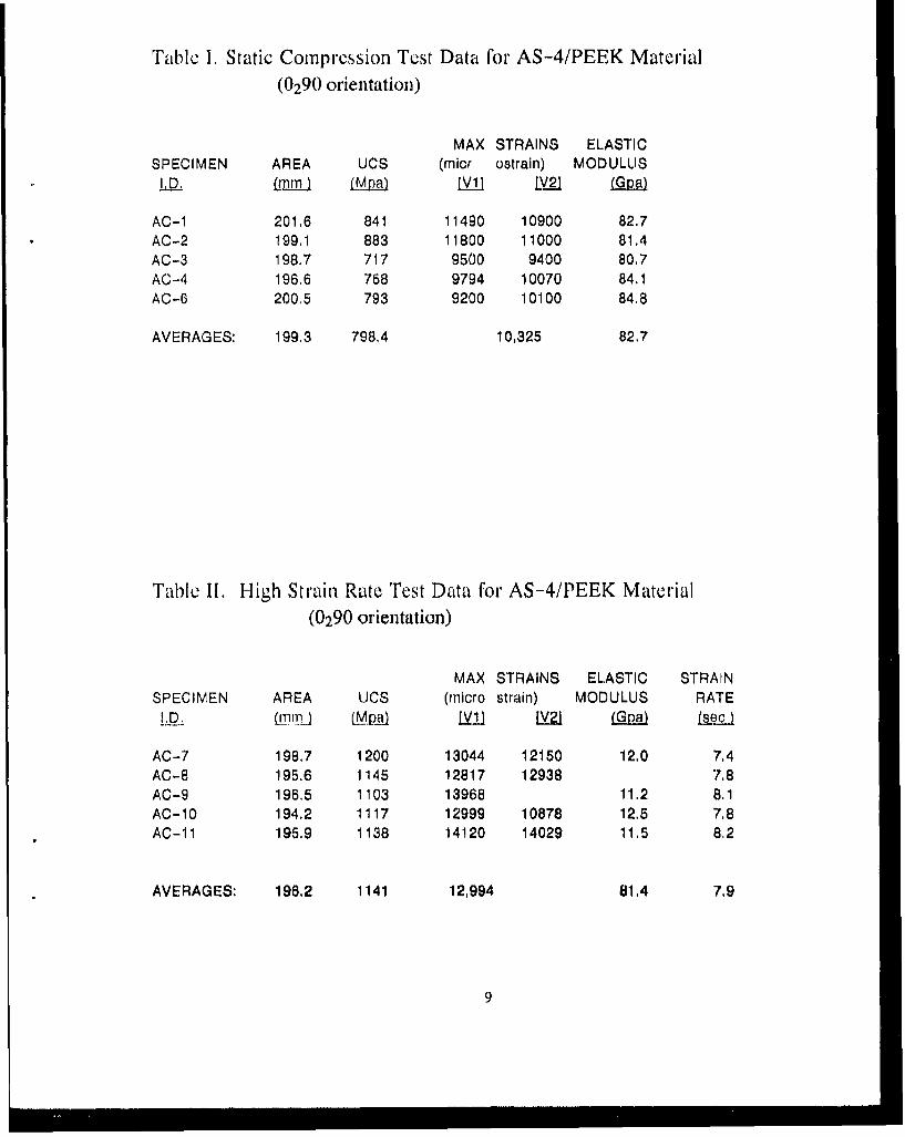
Table 1. Static Compression Test Data for AS-4/PEEK Material(0290 orientation)
MAX STRAINS ELASTICSPECIMEN AREA UCS (micr ostraln) MODULUS
LID. LmrnLI LMix) lvii MQ 21a
AC-1 201.6 841 11490 10900 82.7AC-2 199,1 883 11800 11000 81.4AC-3 198.7 717 9500 9400 80.7AC-4 196.6 758 9794 10070 84.1AC-6 200.5 793 9200 10100 84.8
AVERAGES: 199.3 798,4 10,325 82.7
Table I. High Strain Rate Test Data for AS-4/PEEK Material(0290 orientation)
MAX STRAINS ELASTIC STRAINSPECIMEN AREA UCS (micro strain) MODULUS RATE
/,D. (rnj -) (MPa) [il U2 Ls ec )I
AC-7 198,7 1200 13044 12150 12.0 7,4AC-8 195.6 1145 12817 12938 7.8AC-9 196,5 1103 13968 11.2 8.1AC-10 194,2 1117 12999 10878 12.5 7.8AC-11 195.9 1138 14120 14029 11.5 8.2
AVERAGES: 196.2 1141 12,994 81.4 7.9
9
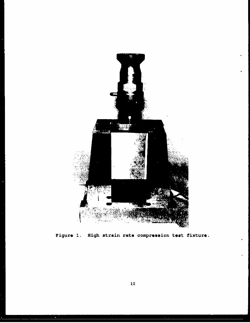
Figure 1. High strain rate compression test fixture.
1.0
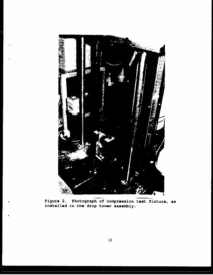
*Figure 2. Photograph of compression test fixture, asinstalled in the drop tower assembly.
* * -- -recessed cap screws
4I-- composite laminate
adhesive Inlerface
0- containment piece
4- contact surface
Figure 3. Schematic of specimen geometry and endcap design.
Static Compression DataAS-4/PEEK Material
0
-1
-2
-3
-4
0200 400 Boo 800
Sresa (MpaI
Figure 4. Typical static compression stress-strain curvefor AS-4/PEEK material.
12
ILnG
144
Io )
4J 41
* * 0,
ii, (I4) C
o~o
N 0
I O
I3 I I
Dynamic Compression DataAS-4/PEEK Material
15
14
12
10'I
5;
4 1
0 042 0.4 0., 0,8IThousands)
Strols (Mph,)Figure 6. Back-to-back longitudinal strain gage signalsfor an AS-4/PREK specimen of 0290 orientation, testeddynamically in compression.
1,2 tAS-4/PEEK Composites. 0200 Orientation
1.2
I I AC 10---
0.8
0.71
0.6
0.4
0.3 S
0.21
0.1
0 ..... .•z ......... . .. .. ....... .... .... ............. - . .. ....- ......~ ... A.. i. I..... .. ..... .... • .
0 2 4 . 0 t 12 14IThousonds)
MicrostralnFigure 7. Static and dynamic compression stress-strainplots for AS-4/P-EK material of 0290 orientation.
14
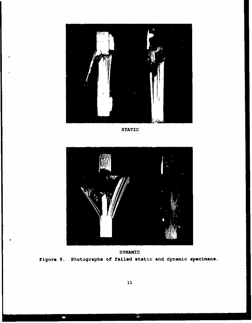
STATIC
DYNAMIC
Figure 8. Photographs of failed static and dynamic specimena.
15
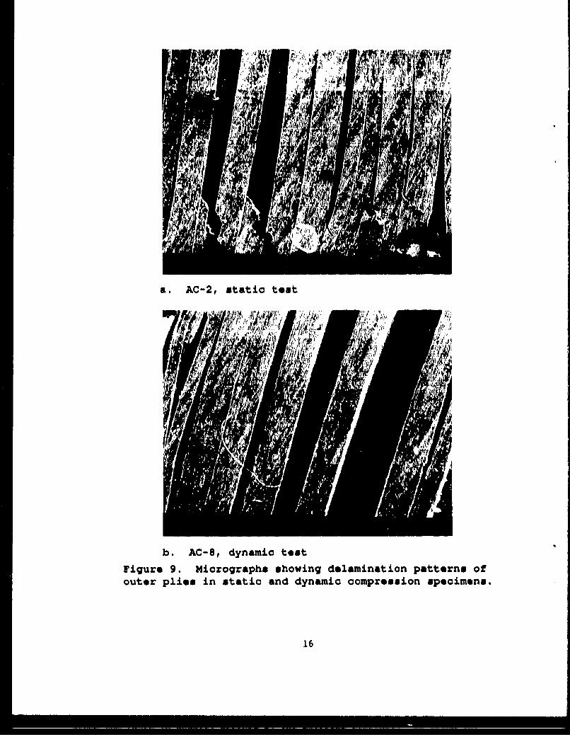
a. AC-2, static teut
b. AC-8, dynamic test
Figure 9. Micrographs showing delamination patterns ofouter plies in static and dynamic compression specimens.
16

a. Static specfimen crush zone (AC-2) 20
b. Dynamic specimen crush zone (AC-8) 22X
Figure 10. Micrographs of crush xone regions in staticand dynamic compression specimens.
17

REFERENCES
1. Daniel, I.M., Hamilton, W.G. and Labedz, R.H., "Strain RateCharacterization of Unidirectional Graphite/Epoxy Composite," Composite
Materials: Testing and Design (Sixth Conference). ASTM STP 787, I.M. Daniel,Ed., American Society for Testing and Materials, 1982, pp. 3 9 3 - 4 1 3 .
2. Twardy, H. and Bergmann, H.W., "Strain Capabilities and Strain Rate Effectsin Epoxy Resins and Laminates," Proceedings of International Symposium onComposite Materials and Structures, June 10-13, 1986, Beijing, China, T. Looand C.Sun Eds., pp. 124-127.
3. Rotem, A. and Lifshitz, J.M., "Longitudinal Strength of UnidirectionalFibrous Composite Under High Rate of Loading," 26th Annual TechnicalConference, Reinforced Plastics/Composites Division, The Society of PlasticsIndustry, 1971.
4. Gifford, L.N., J.R. Carlberg, A.J. Wiggs and B.J. Sickles, "ExplosiveTesting of Full Thickness Precracked Weldments", David Taylor Research CenterReport SSPD-88-172-42, May 1988.
5. Joyce, J.A, and Hackett, E.M., "An Advanced Procedure for J-R CurveTesting Using a Drop Tower," Non-Linear Fracture Mechanics: Volume I - TimeDependent Fracture, ASTM STP 995, A. Saxena, J.D. Landes and J.L. Bassani,Eds., American Society for Testing and Materials, pp. 298-317, Philadelphia,1989.
6. Shuart, M.J., "Failure of Compression-Loaded Multi-Directional CompositeLaminates," AIAA/ASME/ASCE/AHS 29th Structures, Structural Dynamics andMaterials Conference, AIAA Paper No. 88-2293, 1988.
7. Lamothe, R.M. and Nunes, J., "Evaluation of Fixturing for CompressionTesting of Metal Matrix and Polymer/Epoxy Composites", Compression Testing ofHomogeneous Materials and Composites," ASTM STP 808, R. Chait and R. Papirno,Eds., American Society for Testing and Materials, 1983, pp 241-253.
8. Han, K.S., "Compressive Fatigue Behavior of a Glass Fibre-ReinforcedPolyester Composite at 3000 K and 77 0K", Composites, Vol. 14, No. 2, April1983, pp. 145-149.
9. Camponeschi, E.G., "Compression Testing of Thick Section CompositeMaterials," David Taylor Research Report SME-89/73, October 1989.
10. Nicholas, Theodore, "Material Behavior at High Strain Rates," in ImpactDynamics, John Wiley and Sons, N.Y., 1982, pp. 227-332.
19

INITIAL DISTRIBUTION
OUTSIDE CENTER CENTER DISTRIBUTION
Copies Copies Code Name
1 DDRE/LIB I 011 Caplan1 0113
1 CNO/OP98T 1 1721 Chiu1 172.2
3 OCNR 1 172.4 Rasmussen
1 0225 1 173 Beach
1 4325 1 173.2 Critchfield
1 Library 1 2723 Wilhelmi1 28
5 NAVSEA 1 28011 2801 Ventriglio
1 SEA 05M 1 2802 Morton
1 SEA 55Y2 1 28031 SEA 55Y22 1 28091 SEA 55Y3 2 28141 SEA 92R 10 2814 (DMM)
1 2831 NRL 6383 1 284
2 2844
1 NAVPCSCOL 10 2844 (CJW)
1 USNROTCUNAVAMINU MIT
12 DTIC
PRECEDING PAGE 1LANK
21