RESEARCH ARTICLES Optimum surface profile design and … · Optimum surface profile design and...
12
RESEARCH ARTICLES CURRENT SCIENCE, VOL. 90, NO. 11, 10 JUNE 2006 1480 *For correspondence. (e-mail: [email protected]) Optimum surface profile design and performance evaluation of inclined slider bearings A. A. Ozalp* and H. Umur Uludag University, Mechanical Engineering Department, 16059, Gorukle Bursa, Turkey The aim of the present optimization study is to propose an innovative surface profile design by implementing a wavy form on the upper surface, without varying the physical limits of the complete slider-bearing struc- ture. Differential equations governing the fluid-film mass, Reynolds and energy equations, are solved simul- taneously by the iterative transfer matrix approach, which also takes into account the streamwise decrease of lubricant viscosity. Computations indicated that friction coefficient values decrease with wave amplitude in pad inclination ranges of 0–3.77°, 3.3–4.17° and 3.9–4.22° for inlet/exit pressure ratios of 1.01, 3.01 and 5.01 respectively. Wave number is determined to augment the complete pressure distribution inside the bearing and optimum wave number is evaluated as 25 for pressure management. Keywords: Performance optimization, slider-bearing, waviness. WITH extensive applications of slider-bearings in mechani- cal devices, investigations associated with their design and performance optimization have been given privilege. The present industrial needs cover increased load capacity, lowered friction and power consumption and creative de- signs, which in return contribute to considerable progress in computer-aided modelling 1 of slider-bearing lubrica- tion. Analysis on sliding surface definitions is important in predicting the system responses, where application of a wavy pattern to the flow surfaces is a new approach and complicates the numerical-lubrication simulations, as the waviness is defined by two independent variables: ampli- tude and wavelength. A few studies have concentrated on the effects of surface waviness on the lubrication process numerically. A numerical model that takes the sources of nonlinearities, such as surface waviness into account for ball-bearing applications, was developed by Harsha et al. 2 . Rasheed 3 considered the influence of waviness on cylindrical sliding element and proposed a critical wave number range of 1–9 for improved operating conditions. Sottomayor et al. 4 studied roller bearings for various waviness amplitude values and recorded augmented friction coefficients in higher amplitude cases. van Ostayen et al. 5 investigated the performance of a hydro-support with random waviness and Honchi et al. 6 applied a micro-waviness model to an air slider-bearing. Kwan and Post 7 evaluated augmented load values of aerostatic bearings with higher wave amplitudes, whereas Ai et al. 8 showed that the lubricant film thick- ness decreased with waviness in journal-bearings. Journal bearings were also studied by Mehenny and Taylor 9 , who found that the maximum pressure increased with wave num- ber, whereas the numerical model for journal-bearing sys- tems of Liu et al. 10 did not converge efficiently for waviness amplitudes above 6 μm. Performance predictions of the lubrication process under various boundary and geometric conditions have also been considered. Naduvinamani et al. 11 investigated sur- face roughness effects on the load carrying capacity. Lin 12 , and Karkoub and Elkamel 13 inspected the geometric in- fluences on the load values. Effects of input pressure on the work and friction characteristics have been numerically evaluated 14,15 . Kumar et al. 16 performed a numerical study on the surface roughness effects on elastohydrodynamic lubrication of rolling line contacts. Watanabe et al. 17 pre- dicted the influence of structural design features on the frictional characteristics of microgrooved bearings. Lu- bricant flow rate is a major design consideration studied by Luong et al. 18 , both numerically and experimentally for thrust-bearing applications, and by Tian 19 , numerically for porous bearings. Hargreaves and Elgezawy 20 worked on the upper surface discontinuities and so occurring pressure variations in slider-bearings. Non-Newtonian character of the lubricant has a considerable contribution in the lubrication systems; and specifically concentric and eccentric cases have been experimentally investigated 21,22 . Optimization of slider-bearing lubrication is also included in the scope of numerical studies. Stokes and Symmons 23 performed a multi-dimensional optimization on the plasto- hydrodynamic drawing of wires. Lin 24 tried to get an optimum flow cavity for one-dimensional porous curved slider- bearing. Stability is a chief concern for system durability and safety. Instabilities based on pressure perturbations and geometric definitions have been investigated 25–27 . Lubricant viscosity is known to vary significantly with temperature. However, numerical studies on waviness and performance predictions presented above, disregarded
Transcript of RESEARCH ARTICLES Optimum surface profile design and … · Optimum surface profile design and...
RESEARCH ARTICLES
CURRENT SCIENCE, VOL. 90, NO. 11, 10 JUNE 2006 1480
*For correspondence. (e-mail: [email protected])
Optimum surface profile design and performance evaluation of inclined slider bearings A. A. Ozalp* and H. Umur Uludag University, Mechanical Engineering Department, 16059, Gorukle Bursa, Turkey
The aim of the present optimization study is to propose an innovative surface profile design by implementing a wavy form on the upper surface, without varying the physical limits of the complete slider-bearing struc-ture. Differential equations governing the fluid-film mass, Reynolds and energy equations, are solved simul-taneously by the iterative transfer matrix approach, which also takes into account the streamwise decrease of lubricant viscosity. Computations indicated that friction coefficient values decrease with wave amplitude in pad inclination ranges of 0–3.77°°, 3.3–4.17°° and 3.9–4.22°° for inlet/exit pressure ratios of 1.01, 3.01 and 5.01 respectively. Wave number is determined to augment the complete pressure distribution inside the bearing and optimum wave number is evaluated as 25 for pressure management. Keywords: Performance optimization, slider-bearing, waviness. WITH extensive applications of slider-bearings in mechani-cal devices, investigations associated with their design and performance optimization have been given privilege. The present industrial needs cover increased load capacity, lowered friction and power consumption and creative de-signs, which in return contribute to considerable progress in computer-aided modelling1 of slider-bearing lubrica-tion. Analysis on sliding surface definitions is important in predicting the system responses, where application of a wavy pattern to the flow surfaces is a new approach and complicates the numerical-lubrication simulations, as the waviness is defined by two independent variables: ampli-tude and wavelength. A few studies have concentrated on the effects of surface waviness on the lubrication process numerically. A numerical model that takes the sources of nonlinearities, such as surface waviness into account for ball-bearing applications, was developed by Harsha et al.2. Rasheed3 considered the influence of waviness on cylindrical sliding element and proposed a critical wave number range of 1–9 for improved operating conditions. Sottomayor et al.4 studied roller bearings for various waviness amplitude values and recorded augmented friction coefficients in
higher amplitude cases. van Ostayen et al.5 investigated the performance of a hydro-support with random waviness and Honchi et al.6 applied a micro-waviness model to an air slider-bearing. Kwan and Post7 evaluated augmented load values of aerostatic bearings with higher wave amplitudes, whereas Ai et al.8 showed that the lubricant film thick-ness decreased with waviness in journal-bearings. Journal bearings were also studied by Mehenny and Taylor9, who found that the maximum pressure increased with wave num-ber, whereas the numerical model for journal-bearing sys-tems of Liu et al.10 did not converge efficiently for waviness amplitudes above 6 µm. Performance predictions of the lubrication process under various boundary and geometric conditions have also been considered. Naduvinamani et al.11 investigated sur-face roughness effects on the load carrying capacity. Lin12, and Karkoub and Elkamel13 inspected the geometric in-fluences on the load values. Effects of input pressure on the work and friction characteristics have been numerically evaluated14,15. Kumar et al.16 performed a numerical study on the surface roughness effects on elastohydrodynamic lubrication of rolling line contacts. Watanabe et al.17 pre-dicted the influence of structural design features on the frictional characteristics of microgrooved bearings. Lu-bricant flow rate is a major design consideration studied by Luong et al.18, both numerically and experimentally for thrust-bearing applications, and by Tian19, numerically for porous bearings. Hargreaves and Elgezawy20 worked on the upper surface discontinuities and so occurring pressure variations in slider-bearings. Non-Newtonian character of the lubricant has a considerable contribution in the lubrication systems; and specifically concentric and eccentric cases have been experimentally investigated21,22. Optimization of slider-bearing lubrication is also included in the scope of numerical studies. Stokes and Symmons23 performed a multi-dimensional optimization on the plasto-hydrodynamic drawing of wires. Lin24 tried to get an optimum flow cavity for one-dimensional porous curved slider-bearing. Stability is a chief concern for system durability and safety. Instabilities based on pressure perturbations and geometric definitions have been investigated25–27. Lubricant viscosity is known to vary significantly with temperature. However, numerical studies on waviness and performance predictions presented above, disregarded

RESEARCH ARTICLES
CURRENT SCIENCE, VOL. 90, NO. 11, 10 JUNE 2006 1481
this fact due to the complexity of the numerical structure, and performed their computations with a fixed viscosity value for the complete flow domain. Indeed there are also studies that focus on the effects of temperature and lubri-cant properties on the performance of bearings. A linearly narrowing slider-bearing, with heat conduction to the sta-tionary lower surface has been investigated28. Temperature dependency of lubricant viscosity was handled by imposing the temperature distribution of the previous solution set on the nodal viscosity values, until a convergence of 0.05% was achieved for each node between two successive solu-tions. A similar approach was used by Pandey and Ghosh29 on both sliding and rolling contacts. Their convergence criterion for temperature distribution was less sensitive (0.1%) and a unique viscosity value, which corresponds to the average lubricant temperature, was used for the complete flow volume. On the other hand, Yoo and Kim30 took temperature-dependent viscosity into consideration more precisely with a convergence criterion of 0.001%. However, in their study to decrease the computation run time, con-vergence was not applied to each individual temperature value in the flow direction, but for the sum of the com-plete temperature set. Although there have been considerable efforts to determine the boundary condition – cavity structure interactions and their contributions on the performance values of slider-bearings, there is still a gap in this subject matter from the point of upper surface design. The present optimiza-tion study aims to define an innovative design, with the implementation of a wavy form on the upper surface, by keeping the volume of the flow cavity fixed, without varying the physical limits of the complete lubrication structure. To produce a complete overview, computations are performed with three inlet/exit pressure values (β), for six amplitudes (ϕ) and 11 wave numbers (λ) in the pad in-clination (θ) range of 3–5°. Performance optimization outputs are discussed through streamwise pressure (P) variations and with lubricant flow rate (m⋅ ), friction coef-ficient ( f ) and load capacity (W) data for various β, ϕ, λ and θ cases.
Governing equations
Plane slider-bearing performance analysis covers the investi-gation of both momentum and energy transfer in the flow volume. Thus velocity (u), pressure (P) and temperature (T) distributions are the primary concern of the fundamental theory. The outputs of the continuity, momentum and energy equations can be the focused items of the work, but gen-erally the results of the former in the calculation order generate the input set for the following, which puts forth the simultaneous handling of the three equations. As the momentum equation in the –x direction (eq. (1)) inter-prets the relation of viscous shear stress and thermody-namic pressure, the Reynolds equation for one-dimensional
lubricant flows of slider-bearings is given by eq. (2), where Vu, Vl and h stand for the upper and lower surface velocities and pad height respectively31.
2
2
d 1 d,
dd
u P
xy µ= (1)
3
u ld d d.
d 12 d 2 d
V Vh P h
x x xµ
+ = (2)
The amount of energy transferred within the lubricant flow is mainly designated by the streamwise temperature variation, but the volumetric flow rate (qx), the terms re-lated to the momentum loss and the friction loss, which are interconnected with the shear stress (τ), lubricant den-sity (ρ) and specific heat (Cp) are also encountered in eq. (3). Lubricant viscosity (µ) appears in either of the three-main flow and energy equations. Thus the Newtonian vis-cosity–temperature relation is characterized by Vogel’s rule32 of eq. (4), where b, k and ζ are the� viscosity param e-ters.
u u l ld d
,d dp x xT P
C q V V qx x
ρ τ τ= + − (3)
.
b
Tke ζµ ρ += (4)
Although the general form of the momentum, Reynolds and energy equations are as given above, calculations on slider-bearing lubrication are frequently performed in non-dimensional form24,28,33. According to Hwang et al.34, eqs (1)–(3) can be converted into eqs (5)–(7) by using the non-dimensional parameters given in Appendix 1 (A), with the relevant boundary conditions.
2
2
d * d *,
d *d *
u P
xy= * 0 * 1y u= → = and
u *
ex l
* * * ,uVh
y h u Vh V
= = → = = (5)
3 *u
d d * d ** 6( 1) ,
d d * d *
P hh V
x x x = +
*in* 0 *x P P= → = and *
ex* 1 * ,x P P= → = (6)
u vd * d ** ** * * ,d * d *x l xT P
q V qx x
τ τ= + − in** 0 *x T T= → = . (7)
The non-dimensional velocity profile (eq. (8)) can be ob-tained by imposing the boundary conditions in eq. (5).
RESEARCH ARTICLES
CURRENT SCIENCE, VOL. 90, NO. 11, 10 JUNE 2006 1482
d * * *** ( * *) ( 1) 1.d * 2 *uP y y
u y h Vx h
= − + − + (8)
Integration of the velocity profile gives the lubricant flow rate per unit width (eq. (9)).
*
0
1 d * *. ** *d * * ( 1) .12 d * 2
h
uP h
m u y h Vx
−= = + +∫ (9)
The streamwise pressure distribution can be evaluated by integrating the Reynolds equation twice:
* *
u1 in3 3
0 0
*6( 1) d * d * ** d * ,* *
x xV h xP x c P
h h
+= − +∫∫ ∫ (10)
where the integration constant c1 is given in Appendix 1 (B). The load-carrying capacity (W*) and friction force (Ff*) values are obtained by streamwise integration of the film pressure and shear stress distributions respectively, and the ratio gives the friction coefficient ( f * ). Expressing in terms of dimensionless quantities yields eqs (11)–(13).
1
0
* *d *,W P x= ∫ (11)
1
0
* *d *,fF xτ= ∫ (12)
*
**
fFf
W= . (13)
Theoretical model
To generate a realistic overview and to involve the com-bined definitional necessities of both the physical and the thermo-fluid structural information of the complete lubri-cation environment, necessary compounds are chosen from the available recent numerical studies. The slider-bearing in concern here is narrowing in linear style (Fig-ure 1), similar to that of van Ostayen et al.5 and Kwan and Post7. As in the study of Honchi et al.6, the upper bearing surface is kept stationary (Vu = 0 m/s). On the other hand, the lower surface velocity is chosen as Vl = 5 m/s, which is the mean value of the corresponding data of Liu et al.10 (2.55–10.21 m/s) and of Ai et al.8 (8.79 m/s). Bearing length (L) is selected as 10 mm, lying between the choices of Honchi et al.6 (1.25 mm) and Ai et al.8 (14.5 mm). As the inlet height (hin) is fixed as 1 mm, the exit height (hex) range is selected as 0.475–0.125 mm, where these values are within the most frequently applied bearing pad
height and journal-bearing clearance data range of 1–0.0175 mm10,12. The employed inlet and exit heights re-sult in the hin/hex ratio range of 2.1–8 and the mean pad inclination range (θ) of 3–5° (Figure 1). As the resulting hin/hex ratio range is compatible with those of Das35 and Kumar et al.28, where the upper limit of their correspond-ing hin/hex ratio ranges was 6 and 10 respectively, the consequential pad inclination range also suits the applied values of Watanabe et al.17 (θ = 1.78°), Honchi et al.6 (θ = 6.8°) and Dadouche et al.36 (θ = 12°). Investigations have been carried out with SAE 20-type lubricant that has comparable viscosity values with the application of Me-henny and Taylor9 and with the inlet temperature (Tin) of 20°C, which is close to that of Sottomayor et al.4 (24°C). The analysis is based on the fact that unused lubricant is pumped in and emerges to the atmosphere. Therefore inlet (Pin) and exit (Pex) oil pressure values are fixed at 101–501 and 100 kPa respectively, with β = Pin/Pex of 1.01–5.01. The upper surface of the bearing is defined in a convenient way to fit the main aim of the work, by eq. (14), where the wave amplitude and the number of waves are indicated by ϕ and λ respectively. The cosine curve is implemented to the streamwise-structure, where the relative positions of nodes (i) are integrated, in comparison to the total meshing scale (n + 1).
in( ) tan cos 2 .2 1
ih x h x
n
ϕθ π λ
= − + + (14)
To visualize the effects of ϕ and λ on the bearing perform-ance, wave amplitude data are rated in the range 0–200 µm, covering those of Harsha et al.2, Rasheed3, and Liu et al.10. The imposed number of waves is kept within the limits of 5–105, including the most recurrent values in the literature4,6,7.
Computational procedure
To solve the continuity, momentum and energy equations in harmony, the geometric domain of Figure 1 is divided into 1000 sequential cells, where higher numbers, in the early
Figure 1. Schematic layout of slider-bearing with/without wavy structure at the upper surface.

RESEARCH ARTICLES
CURRENT SCIENCE, VOL. 90, NO. 11, 10 JUNE 2006 1483
stages of code development, appeared to increase only the run times and not the accuracy of the streamwise conver-gence. Second-order finite difference marching proce-dure37 in the streamwise direction with a constant cell width (∆x) of L/n, where for the sake of generality the number of cells is denoted by n, is applied for the simula-tion of one-dimensional incompressible lubricant flow. Since the lubricant flow rate (m⋅ ) is constant in the flow direction, equating the derivative of eq. (9) to zero forms a system of n – 1 linear equations, which completely repre-sent the relation of geometric structure, static pressure and velocity distributions. The new implementation (eq. (15)), which can be designated in sigma notation, consists of two coefficient matrices (γ, ϖ) whose elements are mainly defined by the groove geometry and the upper and lower surface velocities of the bearing and can be calculated as given in Appendix 1 (B). As the nodes i = 1 and i = n + 1 represent the inlet and exit planes, the explicit form of the n – 1 equations constitutes the ‘transfer matrix’ (eq. (16)) of the system. Since the left-hand side of eq. (16) is a banded matrix with a bandwidth of three, Thomas algo-rithm37 is used in the evaluation procedure, where the outputs are the scope of continuity and Reynolds equa-tions for nodes i = 2 to n.
*ii iPγ ϖ=∑ , (15)
1 2
1 2
1 2
1 2
1 2
1
0 0 0 0 0 01
0 0 0 0 02
0 0 0 0 03
0 0 0 0 03
0 0 0 0 02
0 0 0 0 0 01
i i
i i i
i i i
i i i
i i i
i i
i
i
i
i n
i n
i n
γ γγ γ γ
γ γ γ
γ γ γγ γ γ
γ γ
+ +
+ +
+ +
+ +
+ +
+
= = =
→ = −
= − = −
→
1in
1
1
1
1
2 ex1
**
*
*
.
*
**
*
ii i
ii
i i
ii
ii
i ii
PP
P
P
P
PP
P
ϖ γϖϖ
ϖϖ
ϖ γ
+
+
+
+
+
++
− = −
(16)
In addition to the inlet conditions and surface velocities, results of the transfer matrix, especially the lubricant flow rate and streamwise pressure gradient also participate as inputs when the temperature variation is under inspection. Superimposing the finite difference sense into the energy equation and rearranging the terms brings up a thermal
relation (eq. (17)) within two consecutive nodes in the mesh, which in return displays the lubricant temperature distribution in the flow direction.
u u l1
* * * d * ** * .d **
i i
x i
V PT x T
xq
τ τ+
+ = ∆ − +
(17)
Evaluation of the temperature-dependent nature of viscosity covers both the traditional isotropic2–14,16–20 method and the present iterative transfer matrix approach, where the classical solution generates the initial set of guesses for the first iteration step. As shown in Figure 2, lubricant viscosity is kept constant in the complete flow volume, being equal to the inlet value, for the isotropic approach. In the first step of the iterative method, the temperature-dependent nodal viscosity variation is calculated by using the temperature distribution of the isotropic approach, to-gether with the viscosity parameters of k, b and ζ. Solv-ing the transfer matrix of eq. (16), with the obtained viscosity distribution, gives the initial temperature set of the iterative method. The computations continue until two consecutive temperature distributions are not more than 0.01% distant at each node within the mesh. The applied convergence criterion (0.01%) is more sensitive than that of Kumar et al.28, and Pandey and Ghosh29. On the other hand, although the criterion (0.001%) of Yoo and Kim30 appears to be more precise, the present method differs from the former by imposing the convergence on each nodal temperature, not on the sum of the complete set. This ap-plication makes the streamwise temperature determinations more reliable, since n + 1 times more control loops for every iteration step exist in the current approach.
Results and discussion
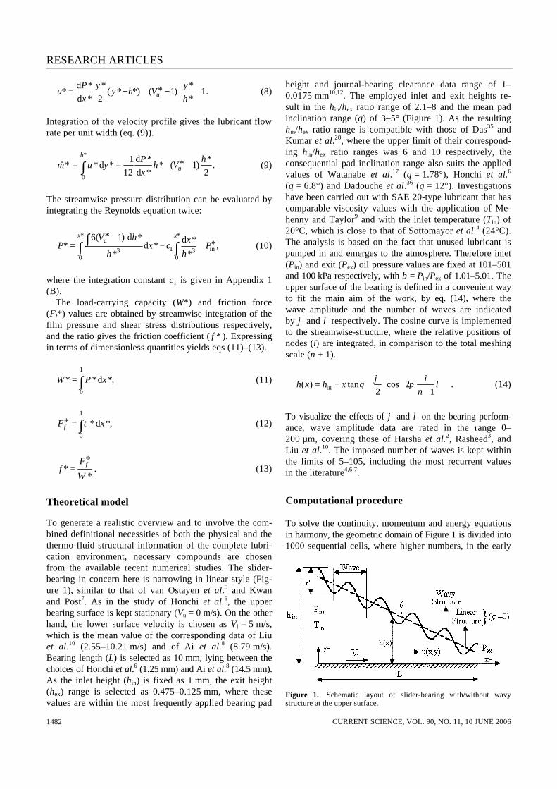
Numerical investigations are performed with wave num-bers (λ) of 5–105, wave amplitude (ϕ) values are in the range of 0–200 µm, slider-bearing pad inclination (θ) is varied between 3 and 5°, and the inlet pressures (β) are 1.01–5.01 times the exit value. Results of various struc-tural-design and boundary condition cases are discussed through lubricant flow rate (m⋅ *), friction factor ( f * ), bearing load (W*) and streamwise variations of lubricant pressure (P*), and displayed in non-dimensional form (*) for the sake of generality. Variations in m⋅ * are given in terms of θ, ϕ and λ–β in Figure 3 a–b respectively. It can be seen from Figure 3 a that, for β = 1.01, lubrication systems with higher ϕ result in lower lubricant flow rate for all slider pad inclinations (θ = 3–5°). Moreover the influence of ϕ on m⋅ * becomes more apparent in cavities with θcr ≥ 3.77° for the λ range of 5–25. Mass flow rate appeared not to be influenced by wave number for small θ; however, as in the case of wave amplitude, above the pad inclination of 3.77° lubricant

RESEARCH ARTICLES
CURRENT SCIENCE, VOL. 90, NO. 11, 10 JUNE 2006 1484
Figure 2. Flow chart of applied computational procedure.
flow rate decreases with higher wave numbers, regardless of the level of ϕ. Figure 3 a additionally indicates that lu-bricant flow rate increases linearly with higher θ in the ϕ range of 0–80 µm (ϕ1 – ϕ3) for 5 ≤ λ ≤ 25. On the other hand, as the wave amplitude is further increased to ϕ4 – ϕ6 (120–200 µm), similar trends of the ϕ1 – ϕ3 cases are dis-played for the θ range of 0–3.77°. Whereas the curves of Figure 3 a imply that beyond θcr = 3.77°, surface designs with ϕ ≥ 120 µm create a counter effect on lubricant flow rate and the outcomes become more remarkable in cases with higher ϕ, λ and θ. Influence of inlet pressure (β), with the combined han-dling of various pad styles for the complete set of ϕ and θ values on lubricant flow rate for the maximum wave number of λ = 105 is displayed in Figure 3 b. The m⋅ * curves for β = 1.01 and λ = 105 are quite similar from the point of both the values attained and the variation styles, to those for β = 1.01 and λ = 25 (Figure 3 a). Thus increasing wave number from 25 to 105 does not create any notice-able change in the lubricant flow rate. On the other hand, increasing β augmented the flow rate values considerably for the complete pad inclinations. However, the increase is more remarkable in the pad structures, particularly with lower inclinations (θ = 3–3.5°), which can be attributed to the resistive character of higher pad inclinations (θ = 4.5–5°) on lubricant flow rate. The maximum ϕ of 200 µm results in a decrease in m⋅ * values of the θ = 5° case by 61, 68 and 71% for β of 1.01, 3.01 and 5.01 respectively. This denotes that the influence of ϕ on m⋅ * increases with β. Moreover, the curves for ϕ = 0–80 µm of the β = 3.01 and 5.01 cases differ from those of β = 1.01 by showing con-tinuous decreasing trends with higher θ, demonstrating increasing slopes with the ascend of inlet pressure. Wata-nabe et al.17 (for journal-bearing lubrication), Tian19 (for
linear porous thrust pad application) and van Ostayen et al.5 (for hydro-support design) also determined the flow rate values to decrease with higher cavity clearance, height and pad inclination. Since the power demand of the system is related with lubricant flow rate, it can directly be con-trolled/lowered by θ and ϕ, especially in cases with higher β. Although the complete curves of β = 3.01 and 5.01 exhibit decreasing character with θ, the decline rates become sharper at θ l 3.77° for the complete ϕ set, putting forth that the pad structure exhibits a critical character at θ = 3.77°, also at β = 3.01–5.01 and λ = 105 cases, similar to the findings with β = 1.01 and λ = 5–25. Combined effects of θ, λ, ϕ and β on friction factor ( f * ) of slider-bearings are presented in Figure 4. Up to θcr = 3.77°, implementation of higher wave number (λ = 5 → 25) or amplitude (ϕ = 0 → 200 µm) did not have any con-tribution on f * for the specific case of β = 1.01 (Figure 4 a). For the pad inclinations of θ < θcr, f
* values appear to in-crease slightly with θ, especially for wave numbers of λ = 5–15, depending on the ϕ level, by 4.8–10.1% in the similar inclination range. However, higher pad inclinations cause significant augmentations in friction factors, where the variations are rather linear with wave amplitude-dependent slopes. Watanabe et al.17 reported enhanced frictional behaviours with lower clearance in journal-bearings, which is similar, from the structural point, with the higher pad inclinations of slider-bearings. On the other hand, Kumar et al.16 modelled the surface roughness dis-tribution for a rolling line contact simulation in surface waviness form and evaluated a direct relation of friction coefficient with roughness amplitude. The current nu-merical results present similar variations in f * with wave amplitude, where the influence of ϕ on the frictional be-haviours of slider-bearings becomes apparent at higher
RESEARCH ARTICLES
CURRENT SCIENCE, VOL. 90, NO. 11, 10 JUNE 2006 1485
Fig
ure
3.
Com
bine
d ef
fect
s of
θ a
nd ϕ
on
lubr
ican
t flo
w r
ate
for
var
ious
(a)
λ (
at β
= 1
.01)
and
(b)
β (
at λ
= 1
05)
case
s.

RESEARCH ARTICLES
CURRENT SCIENCE, VOL. 90, NO. 11, 10 JUNE 2006 1486
Fig
ure
4.
Com
bine
d ef
fect
s of
θ a
nd ϕ
on
fric
tion
coef
fici
ent f
or v
ario
us (
a) λ
(at
β =
1.0
1) a
nd (
b) β
(at
λ =
105
) ca
ses.

RESEARCH ARTICLES
CURRENT SCIENCE, VOL. 90, NO. 11, 10 JUNE 2006 1487
pad inclinations; the effects are more remarkable in higher λ cases. The growth of f * with ϕ can be cross-correlated both with the pad inclination and the hydrodynamic char-acter of lubricant flow. Sharp narrowing cavities result not only in resistive forces on the friction-dominated sec-ondary flows, especially on the solid boundaries, but also cause lower lubricant flow rates, especially at higher ϕ cases with fuller velocity profiles, which in return pro-duce higher shear stress rates on the lower and upper flow surfaces. Variation of friction coefficient values in various inlet pressure cases is presented for λ = 105 in Figure 4 b. The results for β = 1.01 are similar to those in Figure 4 a, im-plying that increasing wave number above 25 caused no sensible effect on f *. Thus λ ≈ 25 can be considered as the design criterion from the point of friction factor. However, the curves for β = 3.01 and 5.01 illustrate addi-tional information both for system design fundamentals and also for the nature of variation style. It can be seen from Figure 4 b that the friction coefficient values of lower pad inclination (θ = 3°) cases rise with higher inlet pressures. However, as the cavities become narrower, the opposite outcome arises in the identical β range. Wong et al.15 also reported augmented friction values with higher β in a high pressure sleeve seal with θ ≤ 3°. As described in Figure 3 b, higher m⋅ * values are a consequence of both higher β and lower θ, which result in augmented momen-tum transfer in the flow direction where the complete flow domain is subjected to significant counter frictional forces. It can also be seen from Figure 4 b that the friction factor values for the β = 1.01 and 3.01, and β = 1.01 and 5.01 cases coincide at the pad inclinations of θ � 3.3 and 3.9° respectively. This implies that as the lubrication sys-tem is to be operated at high inlet pressures, the pad in-clination must also be increased in order to avoid additional power losses due to frictional behaviour. Moreover, at θ � 3.77°, there exist local maxima and minima values both for β = 3.01 and 5.01, which coincide with the slope change location of lubricant flow rate (Figure 3). Figure 4 b also suggests an upper critical θ value, where the friction coefficient values overlap, being independent of ϕ. Indeed, below this upper critical θ value, designs with higher wave amplitudes oppose lower friction forces, where this outcome is contrary to the findings of Figure 4 a and also in converse with the curve portions of the above critical θ cases. It can be said for the critical inclination that the augmented shear rates of fuller velocity due to higher ϕ are exactly equal to the resistive forces of the narrowing cavities with/without waves, where these upper critical values for θ are evaluated as θ ≈ 4.17° and 4.22° for β = 3.01 and 5.01 respectively. Thus there exist suitable pad inclination ranges that become contracted at higher inlet pressures, for optimum frictional character in the slider pad lubrication, where the limits can be ex-pressed as θ ≈ 0–3.77°, θ ≈ 3.3–4.17° and θ ≈ 3.9–4.22° for β = 1.01, 3.01 and 5.01 respectively.
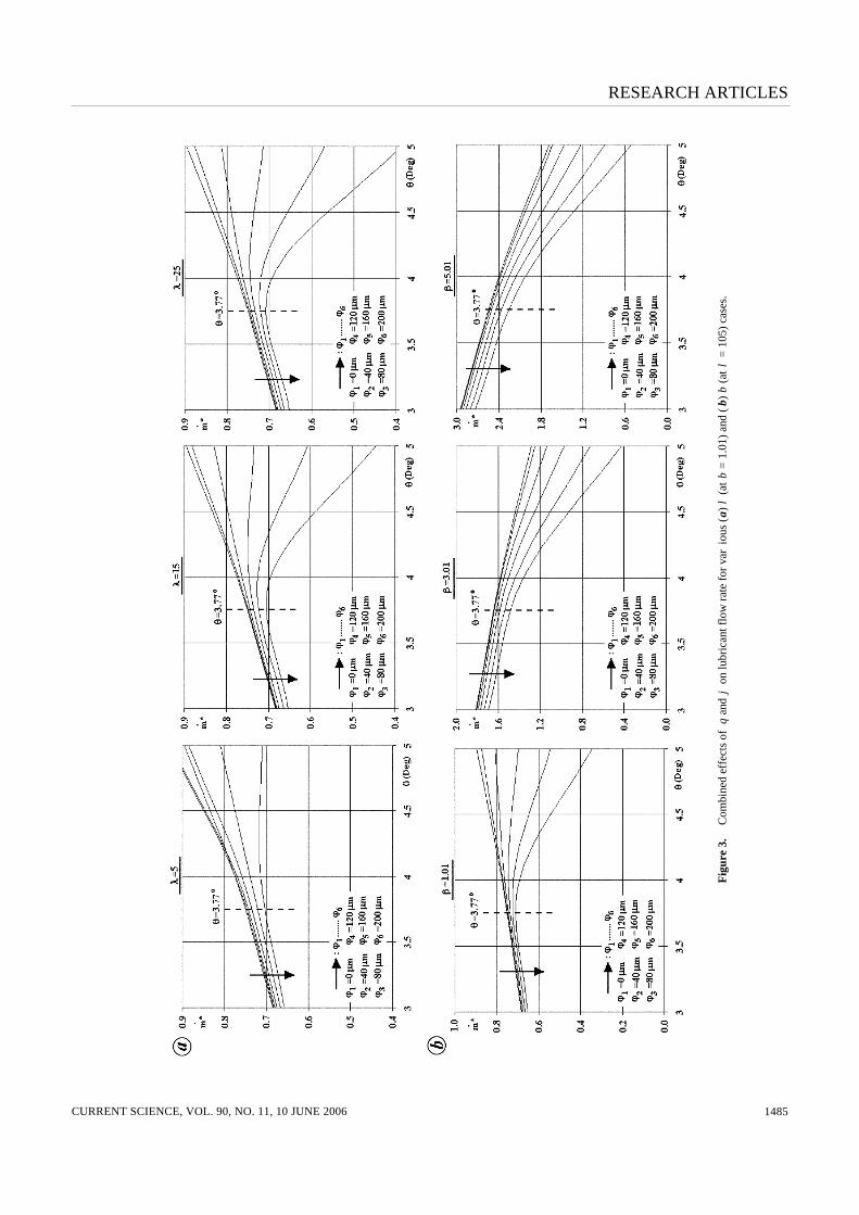
Pressure variation inside the flow cavity is one of the major concerns of the design procedure not only due to its direct relation (eq. (11)) with the load-carrying capac-ity, but also being a possible cause for system damage in cases where the maximum value (P max* ) attains values comparable with the upper boundary of the safety limits. Figure 5 a demonstrates the effects of λ and ϕ on P* dis-tribution for the downstream section (0.6 ≤ x* ≤ 1.0) of the flow cavity for the case with β = 1.01. It can be seen from Figure 5 a that systems with higher number of waves cause the pressure values to rise especially towards the exit plane of the cavity, where points for the maximum values are located. Increasing λ from 5 to 15 resulted in an increase in the P max* value by 42.5% for the specific case with ϕ = 200 µm. Moreover, for the same wave amplitude, raising λ to 25 produced a rise of 6.9% above the P max* value for the λ = 15 case. On the other hand, as the location of the P max* is x* = 0.87 for λ = 5, it is shifted to x* = 0.98 for the system with λ = 25. Thus critical regions for surface failure are more likely to appear in the far down-stream sections of the lubrication volume. Similar to wave number, amplitude values also give rise to pressure; however, this outcome is valid up to the maximum loca-tion, which covers more than 87% of the streamwise length. In the rest of the section, wave amplitude creates a counter effect on the pressure values, and nearly vanishes not only for the portion concerned but also on impact basis with the increase of λ from 5 to 25 (Figure 5 a). Karkoub and Elkamel13 also recorded higher pressure distributions in rectangular gas bearings with higher plate gaps. Figure 5 a further shows that pressure values fluctuate around the neighbourhood of the maximum pressure location, which may cause instabilities and vibration influencing the complete lubrication system, as also described for systems with journal-bearings involving perturbed pressures within the flow cavity26. Hargreaves and Elgezawy20 also reported sudden jumps in pressure values at the pad locations, where either discontinuities or instant cavity enlargements exist. Influence of inlet pressure on the pressure distribution for the specific case of λ = 105 is shown in Figure 5 b. Comparing the β = 1.01 plot with the λ = 25 case of Fig-ure 5 a, implies that increasing the wave number from 25 to 105 results in an augmentation in P max* by just 6.6%. Thus λ � 25 can be considered as an optimum design pa-rameter for the surface definition. Figure 5 b further shows that wave amplitude creates an ascending effect on pressure values for the complete flow volume. Computations point out the critical wave number of λ ≈ 28 for optimum influence of ϕ on the streamwise P* distribution. Moreover, it can also be seen from Figure 5 b that higher inlet pressures shift the complete set of pressure curves up, which, as a conse-quence, will also force the solid boundaries of the lubrica-tion cavities with higher demands. As the pressure fluctuations are limited in the neighbourhood of P max* for 5 ≤ λ ≤ 25 (Figure 5 a), they become more noticeable and
RESEARCH ARTICLES
CURRENT SCIENCE, VOL. 90, NO. 11, 10 JUNE 2006 1488
Fig
ure
5.
Com
bin
ed e
ffec
ts o
f (a
) λ
and
ϕ (
at β
= 1
.01)
and
(b)
β a
nd ϕ
(at
λ =
105
) on
the
stre
amw
ise
vari
atio
n of
sta
tic p
ress
ure
for
θ =
5°.

RESEARCH ARTICLES
CURRENT SCIENCE, VOL. 90, NO. 11, 10 JUNE 2006 1489
Fig
ure
6.
Com
bine
d ef
fect
s of
θ a
nd ϕ
on
load
cap
acity
for
var
ious
(a)
λ (
at β
= 1
.01)
and
(b)
β (
at λ
= 1
05)
case
s.

RESEARCH ARTICLES
CURRENT SCIENCE, VOL. 90, NO. 11, 10 JUNE 2006 1490
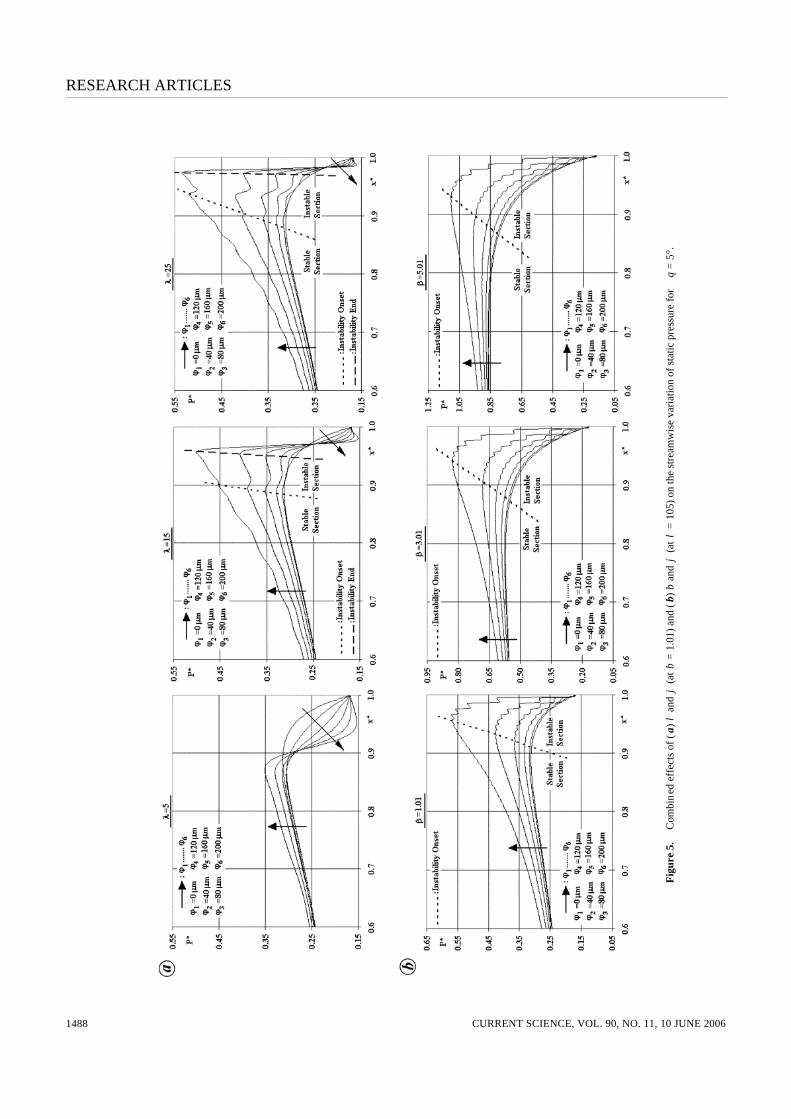
cover wider sectors in the flow volume, downstream of the maximum pressure locations for λ = 105 with 1.01 ≤ β � 5.01, which is good from the point of system stability and durability. Figure 6 a demonstrates the influence of wave number on load carrying capacity (W*) for systems with various ϕ and θ combinations for the specific case of β = 1.01. It can be seen that load values increase with higher wave amplitudes and with lower pad inclinations. However, es-pecially from the geometric structure point of view, λ creates an exceptional impact on W*, where substantial augmen-tations are recorded principally for the range of 5 ≤ λ ≤ 25. In the θ = 3° pad, load values are evaluated to fluctuate for wave numbers of λ > 25 in the complete ϕ set, where the fluctuations become more recognizable in higher ϕ cases. Although comparably smaller than those of the θ = 3° cavity, the instable nature of the load values is still identi-fiable for the cavity with θ = 4°. However, continuously increasing stable style curves are the outcome of further narrowing the flow domain to θ = 5°. Computations indi-cate the critical pad inclinations of θcr = 3.77, 4.17 and 4.22° (for β = 1.01 → 5.01) as the limiting values, where designs with higher pad inclinations are free of fluctuat-ing load values. These determinations also coincide with the upper margins of the lubrication cavity inclinations for optimum frictional character (Figure 4 a). Su and Lie25 also recognized instabilities owing to load fluctuations in air journal-bearings and proposed a multi-orifice assembly to create system damping. Managing the design condition for load management with wave number in the complete set of wave amplitudes considered (ϕ = 40 → 200 µm) and with the design condition for optimal load capacity of W opt* = 0.99 Wλ=105* , generates the optimum λ ranges as 10 → 45, 7 → 11 and 5 → 8 for pad inclinations of 5, 4 and 3° re-spectively. Thus the λ range expands with higher θ, and the upper λ limit is attributed to the top wave amplitude value (ϕ = 200 µm) and decreases with lower ϕ. Variation of load values with θ and ϕ for various β cases is shown in Figure 6 b. The complete set of curves implies that the load values increase considerably with inlet pressure, which is in agreement with the numerical findings of Su and Lie14 on hydrodynamic lubrication of journal-bearings, and those of Karkoub and Elkamel13 on gas lu-bricated rectangular bearings. On the other hand, similar to the determinations of Lin12 and van Ostayen et al.5 for plain slider-bearings, W* decreases significantly with pad inclination. Moreover, the impact of θ becomes more pronounced in cases with higher β, such that the W* values of the θ = 5° pads are 10.81, 10.18 and 10.02% of the corresponding values of the systems with θ = 3° for β of 1.01, 3.01 and 5.01 respectively. Since load has direct re-lationship with pressure distribution (eq. (11)), showing parallelism with discussions on the interactions of wave amplitude and pressure, W* values can also be augmented with ϕ. Wave amplitude-driven load-carrying capacity studies were also carried out by Rasheed3 for cylindrical slid-
ing elements, and by Naduvinamani et al.11 for porous rectangular plates, where W* values were recorded to rise with ϕ. It can be seen from the graph that the influence of ϕ on W* grows in cases with higher θ and lower β, where variations in load values for cavities with θ = 5° among designs with ϕ = 0 and 200 µm are 20.83, 13.48 and 11.42% for β = 1.01, 3.01 and 5.01 respectively; whereas the corresponding variations for the pad inclination of θ = 3° are minor and remained in the range of 0.94–0.66%.
Conclusion
Computational results for performance optimization of inclined slider-bearings, by applying a wavy form on the upper surface, are presented for various inlet/exit pres-sure ratios, wave amplitudes, wave numbers and pad in-clinations. The maximum ϕ = 200 µm results in a decrease in lubricant flow rate values by 61, 68 and 71% for β of 1.01, 3.01 and 5.01 respectively, which denotes that the influence of ϕ on m⋅ * raises with β. On the other hand, waviness caused pressure perturbations around the neighbourhood of the maximum pressure location, which may cause instabilities and vibration. Numerical investi-gations indicate the critical pad inclinations of θcr = 3.77, 4.17 and 4.22°, for β = 1.01, 3.01 and 5.01 respectively, as the limiting values for designs without load fluctuations. Considering the design condition for load management with wave number, optimum λ ranges are determined as 10 → 45, 7 → 11 and 5 → 8 for pad inclinations of 5, 4 and 3° respec-tively, in the complete wave amplitude set considered.
Appendix 1.
A. Non-dimensional parameters Geometric domain is non-dimensionalized by
* ,x
xL
= ex
*y
yh
= , ex
*h
hh
= . (A1)
Velocity terms are non-dimensionalized by
l
*u
uV
= , uu
l
* VV
V= , l
ll
* 1V
VV
= = . (A2)
Design considerations are non-dimensionalized by
2ex
2l
* ,Wh
WV Lµ
= f exf
l
* F hF
V Lµ= . (A3)
Primary flow data are non-dimensionalized by
2ex
l
*Ph
PV Lµ
= , 2ex p
l
*Th C
TV L
ρ
µ= . (A4)
Secondary flow data are non-dimensionalized by
ex l
* xx
h V= ,
ex l
.. * ,
mm
h Vρ= ex
l
*h
V
ττ
µ= . (A5)

RESEARCH ARTICLES
CURRENT SCIENCE, VOL. 90, NO. 11, 10 JUNE 2006 1491
B. Supplementary functions
The integrating constant c1, in eq. (10), can be determined us-ing a manometric pressure boundary condition: P* (x* = 1) = 0, together with the two new functions as given below:
1
01 1
0
( *)d *
,
( *)d *
g h x
c
f h x
=∫
∫
u
3
*6( 1)d *( *) ,
*
V hg h
h
+= ∫
3
1( *)
*f h
h= . (B1)
The elements of the transfer matrix, given by eq. (16), are defined by two single-row sub-matrices (γ1…n+1, ϖ1…n+1), whose elements can be computed as follows:
3*i ihγ = , 3 3
1 1* *[ ],i i ih hγ + += − +
32 1
*i ihγ + += , u 1* **6( 1) *( )i i iV x h hϖ += + ∆ − , (B2)
where i defines the successive node numbers in the streamwise direction.
1. Ozalp, A. A. and Ozel, S. A., An interactive software package for the investigation of hydrodynamic slider bearing lubrication. Comp. Appl. Eng. Educ., 2003, 11, 103–115.
2. Harsha, S. P., Sandeep, K. and Prakash, R., The effect of speed of balanced rotor on nonlinear vibrations associated with ball bear-ings. Int. J. Mech. Sci., 2003, 45, 725–740.
3. Rasheed, H. E., Effect of surface waviness on the hydrodynamic lubrication of a plain cylindrical sliding element bearing. Wear, 1998, 223, 1–6.
4. Sottomayor, A., Campos, A. and Seabra, J., Traction coefficient in a roller-inner ring EHD contact in a jet engine roller bearing. Wear, 1997, 209, 274–283.
5. van Ostayen, R. A. J., van Beek, A. and Ros, M., A parametric study of the hydro-support. Tribol. Int., 2004, 37, 617–625.
6. Honchi, M., Kohira, H. and Matsumoto, M., Numerical simulation of slider dynamics during slider-disk contact. Tribol. Int., 2003, 36, 235–240.
7. Kwan, Y. B. P. and Post, J. B., A tolerancing procedure for inher-ently compensated, rectangular aerostatic thrust-bearings. Tribol. Int., 2000, 33, 581–585.
8. Ai, X., Cheng, H. S., Hua, D., Moteki, K. and Aoyama, S., A fi-nite element analysis of dynamically loaded journal-bearings in mixed lubrication. Tribol. Trans., 1998, 41, 273–281.
9. Mehenny, D. S. and Taylor, C. M., Influence of cicumferential waviness on engine bearing performance. Proc. Inst. Mech. Eng., Part C, 2000, 214, 51–61.
10. Liu, W. K., Xiong, S., Guo, Y., Wang, Q. J., Wang, Y., Yang, Q. and Vaidyanathan, K., Finite element method for mixed elastohy-drodynamic lubrication of journal-bearing systems. Int. J. Num. Methods Eng., 2004, 60, 1759–1790.
11. Naduvinamani, N. B., Fathima, S. T. and Hiremath, P. S., Effect of surface roughness on characteristics of couple stress squeeze film between anisotropic porous rectangular plates. Fluid Dyn. Res., 2003, 32, 217–231.
12. Lin, J. R., Squeeze film characteristics of finite journal-bearings: couple stress fluid model. Tribol. Int., 1998, 31, 201–207.
13. Karkoub, M. and Elkamel, A., Modelling pressure distribution in a rectangular gas bearing using neural networks. Tribol. Int., 1997, 30, 139–150.
14. Su, J. C. T. and Lie, K. N., Rotation effects on hybrid hydrostatic/hydrodynamic journal-bearings. Ind. Lubr. Tribol., 2001, 53, 261–269.
15. Wong, P. L., Xu, H. and Zhang, Z., Performance evaluation of high pressure sleeve seal. Wear, 1997, 210, 104–111.
16. Kumar, P., Jain, S. C. and Ray, S., Study of surface roughness ef-fects in elastohydrodynamic lubrication of rolling line contacts us-ing a deterministic model. Tribol. Int., 2001, 34, 713–722.
17. Watanabe, K., Natsume, J., Hashizume, K., Ozasa, T, Noda, T. and Masuda, Y., Theoretical analysis of bearing performance of microgrooved bearing. JSAE Rev., 2000, 21, 29–33.
18. Luong, T. S., Potze, W., Post, J. B., van Ostayen, R. A. J. and van Beek, A., Numerical and experimental analysis of aerostatic thrust-bearings with porous restrictors. Tribol. Int., 2004, 37, 825–832.
19. Tian, Y., Static study of the porous bearings by the simplified fi-nite element analysis. Wear, 1998, 218, 203–209.
20. Hargreaves, D. J. and Elgezawy, A. S., A new model for combined Couette and Poiseuille flows in the transverse groove of a plane inclined slider-bearing. Tribol. Int., 1998, 31, 297–303.
21. Nouri, J. M., Umur, H. and Whitelaw, J. H., Flow of Newtonian and non-Newtonian fluids in concentric and eccentric annuli. J. Fluid Mech., 1993, 253, 617–641.
22. Nouri, J. M. and Whitelaw, J. H., Flow of Newtonian and non-Newtonian fluids in an eccentric annulus with rotation of the inner cylinder. Int. J. Heat Fluid Flow, 1997, 18, 236–246.
23. Stokes, M. R. and Symmons, G. R., Numerical optimisation of the plasto-hydrodynamic drawing of narrow strips. J. Mater. Proc. Technol., 1996, 56, 733–742.
24. Lin, J. R., Optimal design of one-dimensional porous slider-bearings using the Brinkman model. Tribol. Int., 2001, 34, 57–64.
25. Su, J. C. T. and Lie, K. N., Rotor dynamic instability analysis on hybrid air journal-bearings. Tribol. Int., 2006, 39, 238–248.
26. Kumar, A., Conical whirl instability of turbulent flow hybrid po-rous journal-bearings. Tribol. Int., 1998, 31, 235–243.
27. Czolczynski, K., Stability of the rotor supported in gas journal-bearings with a chamber feeding system. Wear, 1997, 210, 220–236.
28. Kumar, B. V. R, Rao, P. S. and Sinha, P., A numerical study of performance of a slider-bearing with heat conduction to the pad. Finite Elements Anal. Des., 2001, 37, 533–547.
29. Pandey, R. K. and Ghosh, M. K., A thermal analysis of traction in elastohydrodynamic rolling/sliding line contacts. Wear, 1998, 216, 106–114.
30. Yoo, J. G. and Kim, K. W., Numerical analysis of grease thermal elastohydrodynamic lubrication problems using the Herschel–Bulkley model. Tribol. Int., 1997, 30, 401–408.
31. Shigley, J. E., Mechanical Engineering Design, McGraw Hill, 1986. 32. Cameron, A., Basic Lubrication Theory, Prentice Hall, 1981. 33. Ghosh, M. K. and Gupta, K., Thermal effect in hydrodynamic lu-
brication of line contacts – piezoviscous effect neglected. Int. J. Mech. Sci., 1998, 40, 603–616.
34. Hwang, C. C., Lin, J. R. and Yang, R. F., Lubrication of long po-rous slider-bearings (use of the Brinkman–extended Darcy model). JSME Int. J. (Ser. B), 1996, 39, 141–148.
35. Das, N. C., A study of optimum load-bearing capacity for slider-bearings lubricated with couple stress fluids in magnetic field. Tribol. Int., 1998, 31, 393–400.
36. Dadouche, A., Fillon, M. and Bligoud, J. C., Experiments on thermal effects in a hydrodynamic thrust-bearing. Tribol. Int., 2000, 33, 167–174.
37. Chapra, S. C. and Canale, R. P., Numerical Methods for Engi-neers, McGraw Hill, 1990.
Received 11 June 2005; revised accepted 14 March 2006