
Kullback-Leibler aggregation and misspecified generalized ...
Research ArticleSymmetric Kullback-Leibler Metric Based TrackingBehaviors for Bioinspired Robotic Eyes
Hengli Liu Jun Luo Peng Wu Shaorong Xie and Hengyu Li
School of Mechatronic Engineering and Automation Shanghai University Shanghai 200072 China
Correspondence should be addressed to Hengyu Li lihengyushueducn
Received 8 July 2015 Revised 5 October 2015 Accepted 21 October 2015
Academic Editor Cecilia Laschi
Copyright copy 2015 Hengli Liu et al This is an open access article distributed under the Creative Commons Attribution Licensewhich permits unrestricted use distribution and reproduction in any medium provided the original work is properly cited
A symmetric Kullback-Leibler metric based tracking system capable of tracking moving targets is presented for a bionic sphericalparallelmechanism tominimize a tracking error function to simulate smooth pursuit of human eyesMore specifically we propose areal-timemoving target tracking algorithmwhichutilizes spatial histograms taking into account symmetricKullback-LeiblermetricIn the proposed algorithm the key spatial histograms are extracted and taken into particle filtering framework Once the targetis identified an image-based control scheme is implemented to drive bionic spherical parallel mechanism such that the identifiedtarget is to be tracked at the center of the captured images Meanwhile the robot motion information is fed forward to develop anadaptive smooth tracking controller inspired by the Vestibuloocular Reflex mechanism The proposed tracking system is designedto make the robot track dynamic objects when the robot travels through transmittable terrains especially bumpy environment Toperform bumpy-resist capability under the condition of violent attitude variation when the robot works in the bumpy environmentmentioned experimental results demonstrate the effectiveness and robustness of our bioinspired tracking system using bionicspherical parallel mechanism inspired by head-eye coordination
1 Introduction
Robot vision systems are crucial to recognize and acquiresurrounding information for mobile robots Target trackingtarget recognition surrounding perception robotic localiza-tion and attitude estimation are the most popular topics inrobotics And the target tracking function has emerged as asignificant aspect for Human Robot Interaction (HRI) cam-eraMotion-Disturbance Compensation (MDC) and trackingstabilization
The robot motion information is commonly used tokeep the camera stabilization and compensate small rotationor movements of the camera These systems used inertialsensors and visual cues to compute the motion informationof the camera Jung and Sukhatme [1] developed a Kanade-Lucas-Tomasi (KLT) based motion tracking system for amoving target using a single camera on a mobile robotHwangbo et al [2 3] also developed a gyro-aided KLT featuretracking method that remained robust under fast camera-ego rotation conditions Park et al [4] proposed an ExtendedKalman Filter (EKF) based motion data fusion scheme for
visual object tracking by autonomous vehicles Jia et al [5]also proposed a scheme of joint of visual features and thevehiclersquos inertialmeasurements for visual object identificationand tracking Hol et al [6] used a multirate EKF by fusingmeasurements from inertial sensors (accelerometers and rategyroscopes) and vision to estimate and predict position andorientation (pose) of a camera for robust real-time tracking
Recently biomimetic systems were extensively investi-gated by adopting the movement mechanics of human eyeThe development of eyeballrsquos neurophysiology provides alarge amount of data and theory foundation for building upthe controlling model of eye movement Among the severaltypes of eye movements smooth tracking and gaze stabiliza-tion play a fundamental role Lenz et al [7] developed anadaptive gaze stabilization controller inspired by the Vestibu-loocular Reflex (VOR) It integrated inertial and visualinformation to drive the eyes in the opposite direction to headmovement and thereby stabilized the image on the retinaunder dynamic changes Shibatarsquos biological oculomotorsystems [8] used human-eyersquos VOR and Optokinetic Reflex
Hindawi Publishing CorporationApplied Bionics and BiomechanicsVolume 2015 Article ID 714572 11 pageshttpdxdoiorg1011552015714572
2 Applied Bionics and Biomechanics
(OKR) to improve the gaze stabilization of vision system Achameleon-inspired binocular ldquonegative correlationrdquo visualsystem (CIBNCVS) with neck [9] was designed to achieveswift and accurate positioning and tracking Avni et al [10]also presented a biologically motivated approach of track-ing with independent cameras inspired by chameleon-likevisual system Law et al [11] described biologically con-strained architecture for developmental learning of eye-headgaze control on an iCub robot Xie et al [12] proposeda biomimetic control strategy of on-board pan-tilt-zoomcamera to stabilize visual tracking from a helicopter based onphysiological neural path of eyemovement control Vannucciet al [13] established an adaptive model for robotic controlable to perform visual pursuit with prediction of the targetmotion Falotico et al [14] employed ldquocatch-uprdquo saccademodel to fixate the object of interest in case of movingtargets in order to obtain a human-like tracking systemCompared with the classical control methods the advantagesof using a bionic controller make the robot easily adaptedto transmittable terrains and track moving targets stablyInspired by the excellent work we tackle turbulence problemof tracking when the robots travel through bumpy terrainsusing a tracking system that is bumpy-resist capability
Furthermore with the development of anatomy of humaneye themovementmechanics of the human eye have arousedmuch interest in bionic engineering Humanoid robot James[15 16] was equipped with two artificial eyes which canpan and tilt independently (totally 4 DOFs) Thus the iCub[17 18] also had two artificial eyes with 3 DOFs offeringviewing and tracking motions Wang et al [19] devised anovel humanoid robot eye which is driven by six pneumaticartificial muscles (PAMs) and rotates with 3 DOFs Bioin-spired actuators and mechanisms have been proposed to panand tilt a camera with comparable characteristics as a humaneye [20 21] Tendon-driven robot eye [22] was presentedutilizing a mechanical base of the geometry of the eye and ofits actuation system behind the implementation of Listingrsquoslaw Gu et al [23] presented an artificial eye implant withshapememory alloys (SMAs) driven by a small servomotor Aminiature artificial compound eye called the curved artificialcompound eye (CurvACE) [24] was endowed using similarmicromovements to those occurring in the flyrsquos compoundeye
Many bionic eyes have been presented as mentionedabove However spherical parallel mechanism (SPM) has acompact structure excellent dynamic performance and highaccuracy in addition a 3-DOF SPM is in line with the struc-tural design of the bionic eye 3-DOF SPMs attract decentamount of interest for this reason A large number of these 3-DOF SPM bionic eyes have been proposed An artificial eye[25 26] for humanoid robots has been devised to be smallin size and weight as well as to imitate the high dynamicmovements of the human eye The ldquoAgile Eyerdquo [27] is a high-performance parallel mechanism which has the capability oforienting a camera mounted end effector within a workspacelarger than that of a human eye and with velocities andaccelerations larger than those of the human eye Bang et al[28] design a 3-DOF anthropomorphic oculomotor systemto match the human-like eyersquos performance capabilities Our
mechanism platform is inspired by these excellent works andplays a vital role in tracking dynamic objects
Tracking a dynamic object when a robot performs itsnormal motion is common in application To keep smoothlytracking moving objects we develop a bioinspired trackingsystem that is extensively used when the robot works inbumpy environment orwith dynamic disturbance in this paperWith active robot vision an image-based feedback trackingsystem is presented for our bionic SPM to minimize trackingservoing capable of tracking moving target when the robotmoves across in bumpy environment More specifically wepropose a real-time moving target tracking algorithm whichutilizes spatial histograms and symmetric Kullback-Leibler(SKL) metric integrated in particle filtering framework toachieve automatic moving target tracking and gaze stabiliza-tion In the proposed algorithm the key spatial histogramsare extracted and taken into particle filtering frameworkAn image-based feedback control scheme is implementedto drive bionic SPM such that the identified target is to betracked at the center of the captured images Meanwhilethe robot motion information is fed forward to developan adaptive smooth tracking controller bioinspired by theVORmechanism To perform good specification we test ourvision stability system under the condition of violent attitudevariation when the robot works in bumpy environment
From a robotics point of view our system is biologicallyinspired While smooth tracking is employed to create aconsistent perception of the surrounding world the inter-action with environment is also used to adjust the controlmodel involved in the smooth tracking generation Actionand perception are tightly coupled in a bidirectional wayperception triggers an action and the output of action changesthe perception Meanwhile the robot motion information isfed forward inspired by the VOR mechanism to stabilizesmooth tracking
The paper is organized as follows Section 2 introducesbionic issues and design of our bionic SPM Section 3 pro-poses visual tracking based on symmetric Kullback-Leiblermetric spatiograms Our bionic eye plant control system isdescribed in Section 4 Experimental results are shown inSection 5 Section 6 presents our conclusion
2 Design of Human-Eye-InspiredPTZ Platform
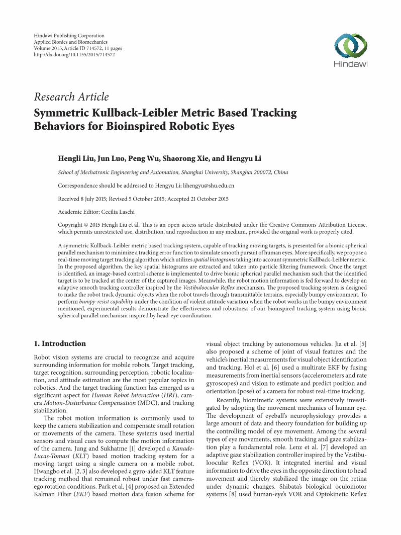
21 Human-Eyersquos Movement Mechanism Each eye is con-trolled by three complementary pairs of extraocular musclesas shown in Figure 1(a) The movement of each eye involvesrotating the globe of the eye in the socket of the skull Becauseof minimal translation during its movement the eye can beregarded as a spherical joint with an orientation defined bythree axes of rotation (horizontal vertical and torsional) Butin our implementation and development of a simulator weview eye movement with no translation for simplicity
The medial rectus turns eye inward and thus lateralrectus outward Therefore they form a pair to control thehorizontal position of the eye In contraction to the pair ofmedial rectus and lateral rectus the actions of the other two
Applied Bionics and Biomechanics 3
Trochlea
Superior oblique
Superior rectus
Levator (cut)
Optic nerve
Inferior rectus
Lateral rectus
Inferior oblique
(a) (b)
Figure 1 Development of bionic eye plant (a) Muscles of the eye Six muscles arranged in three pairs control the movements of the eye asshown here in a cutaway view of the eye in its socket or orbit (b) Structure of our SPM prototype
pairs of muscles are more complex When the eye is centeredin the orbit the primary effect of the superior and inferiorrectus is to rotate up or rotate down the eye However whenthe eye is deviated horizontally in the orbit thesemuscles alsocontribute to torsion the rotation of the eye around the line ofsight that determines the orientation of images on the retina
The primary effect of the superior and inferior obliquesis to turn eyes downward and upward when the eye does notdeviate from horizontal position So do superior rectus andinferior rectus In addition these muscles also determine thevertical orientation of the eye
Smooth pursuit eye movements slowly rotate the eyesto compensate for any motion of the visual target and thusact to minimize the blurring of the targetrsquos retinal imagethat would otherwise occur We implement smooth targettracking continuously adjusted by visual feedback about thetargetrsquos image (retinal image)
Kinematic characteristics of SPM and the mechanics ofeye movements are very similar [29] Both have a 3-DOFspherical movement and rotating globe is the center of thesphere SPM also has a compact structure excellent dynamicperformance and high accuracy so 3-DOF SPM is in linewith the structural design of the bionic eye to replicate theeye movement
The eyeball is seen as a sphere with a rotation centerwhenit rotates Inspired by the mechanics of eye movements andactive robotic vision we presented a new bionic eye prototypebased on SPM which is made up of an eye-in-hand system asshown in Figure 1(b)
Because the eye is free to rotate in three dimensionseyeballs can keep retinal images stable in the fovea whenthey track moving target In our work we proposed twomain points about structural requirements inspired by thehuman eyes (1) camera center must be located at the centerof ldquoeyeballrdquo to ensure that the angle of image planes betweentwo different positions keeps identical with the rotation ofldquoeyeballrdquo (2) in the process of eyemovement anymechanicalcomponent except the ldquoeyeballrdquo cannot exceed the plane ofthe center of the sphere as much as possible to ensure thatwhen themovement of the ldquoeyeballrdquo occurs they do not blockthe sight of the camera and do not interfere with the robotface
22 Oculomotor Plant Compensation of VOR In the human-eye VOR a signal from the vestibular system related tohead velocity which is encoded by semicircular ducts isused to drive the eyes in the opposite direction to the headmovement The VOR operates in feedforward mode andas such requires calibration to ensure accurate nulling ofhead movement The simplicity of this ldquothree-neuron arcrdquotogether with the relatively straightforward mechanics of theeye plant has long made the VOR an attractive model forexperimental and computational neuroscientists seeking tounderstand cerebellar function To abolish image motionacross the retina the vestibular signal must be processedby neural circuitry which compensates for the mechanicalproperties of the oculomotor plant The VOR is therefore aparticular example of motor plant compensation Horizontaland vertical and angular and linear head movement motivatethe appropriate combinations of six extraocular muscles inthree dimensions
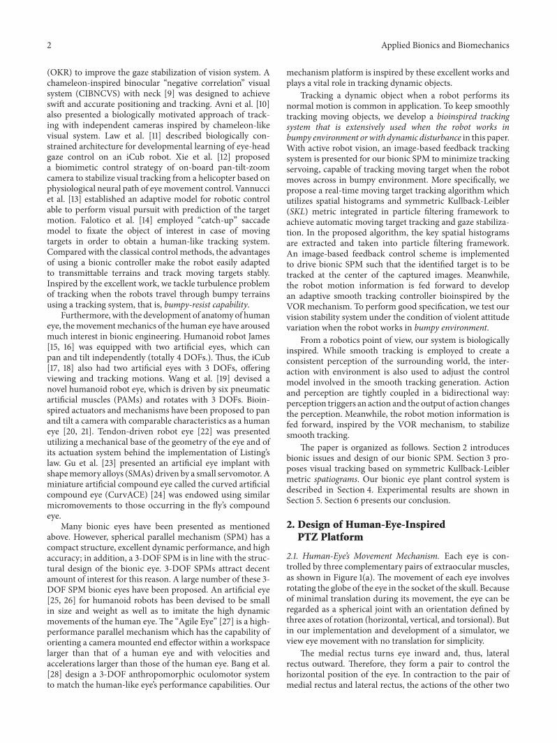
23 Kinematics of Human-Eye-Inspired PTZ Platform Spher-ical parallel mechanism consists of an upper layer and a baseconnected by three pairs of identical kinematic subchains asshown in Figure 2 In each chain there is one fixed revolutejoint 119911
119894and two free revolute joints 119909
119894and 119910
119894connecting the
proximal link to the distal link and the distal link to the upperlayer respectively The axes of all revolute joints intersect ata common point 119874 which is referred to as the rotationalcenter The plane passing through the point 119874 and becomingparallel with the base is called the sphere center plane alsoseen as Listingrsquos plane of eyeball 120572
1 1205722 1205731 1205732 and 120578 are
the parameters of this mechanism where 1205721and 120572
2are the
structural angle of the lower link and upper link 1205731and 120573
2
are the half-cone angle of the upper platform and the baseand 120578 is the structural torsion angle of initial state of the upperplatform and the base namely the initial torsion angle
Figure 2 demonstrates the kinematics of our SPM plat-form and the kinematic equation of the SPM is given by [30]
120579 = 119869 (1205721 1205722 1205731 1205732 120578 120601119909 120601119910 120601119911)120596 (1)
4 Applied Bionics and Biomechanics
Eye plant
Distal link
Proximal link
Base
Sphere centredatum
ZZ13
1205732
Z0Y
X
X0
Z11
Y0
1205731
1205721
1205722
Z12
O
Figure 2 Kinematic sketch of a spherical parallel manipulator
where 120579 = (
1205791
1205792
1205793) is the angular velocity vector input of
the motor120596 = (120596119909 120596119910 120596119911) is the angular velocity vector out-
put of the upper platform and 119869 is the Jacobian matrix whichis decided by themechanical parameter (120572
1 1205722 1205731 1205732 and 120578)
and the eyeball posture (120601119909 120601119910 and 120601
119911) 1205721and 120572
2are the
structural angles of lower link and upper link respectively1205731and 120573
2are the angles of base and upper platform The
proposed PTZ platform has similar kinematics to the humaneye as shown in Figure 3
3 SKL-Based Particle Filter Visual Tracking
31 Spatial Histograms Spatiogram Color histogram is oneof the common target models which is just a statistic ofdifferent colors in the entire picture in proportion withoutconcern for spatial location of each color Therefore it is notrather sensitive to rotation but suitable for nonrigid or proneto deformation modeling target objects Targets based onthis model are vulnerable to backgrounds which have similarcolor distribution or other interference thereby causing thetarget tracking failure In this paper we improve the particlefilter algorithm based on a new target model spatiogram[31] which adds the pixel coordinate information to thetraditional color histogram and uses SKLmetricThe second-order spatiogram can be described as follows
ℎ (119887) = 119899119887120583119887 Σ119887 119887 = 1 119861 (2)
where 119861 is the total number of the intervals and 119899119887120583119887 Σ119887
is the probability of each interval coordinate mean andcovariance matrix respectively They can be calculated usingthe formula as follows
119899119887=
1
119873
119873
sum
119895=1
120575119895119887
120583119887=
1
119873 lowast 119899119887
119873
sum
119895=1
x119895120575119895119887
Σ119887=
1
119873 lowast 119899119887minus 1
119873
sum
119895=1
(x119895minus 120583119887) (x119895minus 120583119887)
119879
120575119895119887
(3)
119861 is the total number of pixels within the target area x119895
=
[119909119895 119910119895]119879 is the coordinate position of the 119895th pixel and 120575
119895119887=
1 denotes that the 119895th pixel is quantized to the 119887th intervalwhile 120575
119895119887= 0 indicates that the 119895th pixel is quantized to other
intervals
32 SKL-Based Particle Filter In order to apply the spa-tiogram to target tracking we need to select a methodto measure the similarity metrics of the spatial histogrambetween the targets and the candidate targets We select theSKL-based coefficient of similarity metrics to measure thesimilarity of the target spatiogram ℎ(119887) = 119899
119887120583119887 Σ119887 and
candidate target spatiogram ℎ1015840(119887) = 119899
1015840
1198871205831015840
119887 Σ1015840
119887
Given a spatiogram ℎ(119887) = 119899119887120583119887 Σ119887 we use a Gaussian
distribution to describe the spatial distribution of all thepixels in each section The distribution of the 119887th section canbe described as
119891119887 (x) =
1
21205871003816100381610038161003816Σ119887
1003816100381610038161003816
12exp [minus
1
2
(x minus 120583119887)119879Σminus1
119887(x minus 120583
119887)] (4)
where 120583119887is the mean value of all coordinates of the pixels of
the 119887th interval and Σ119887is the mean covariance matrix of all
coordinates of the pixels of the 119887th intervalThe KL distance between the Gaussian distribution 119891
119887(x)
and the Gaussian distribution 1198911015840
119887(x) can be obtained by a
closed form solution which is calculated using the followingformula
KL (119891119887 1198911015840
119887) =
1
2
[log(
10038161003816100381610038161003816Σ1015840
119887
10038161003816100381610038161003816
1003816100381610038161003816Σ119887
1003816100381610038161003816
) + Tr ((Σ1015840119887)
minus1
Σ119887) minus 119889
+ (120583119887minus 1205831015840
119887)
119879
(Σ1015840
119887)
minus1
(120583119887minus 1205831015840
119887)]
(5)
where 119889 is the spatial dimension (for spatiogram 119889 = 2)Similarly we can get the KL distance between the Gaussiandistribution 119891
1015840
119887(x) and the Gaussian distribution 119891
119887(x)
KL (1198911015840
119887 119891119887) =
1
2
[log(
1003816100381610038161003816Σ119887
1003816100381610038161003816
1003816100381610038161003816Σ1015840
119887
1003816100381610038161003816
) + Tr (Σminus1119887
Σ1015840
119887) minus 119889
+ (1205831015840
119887minus 120583119887)
119879
Σminus1
119887(1205831015840
119887minus 120583119887)]
(6)
The SKL distance of the two Gaussian distributions of 119891119887(x)
and 1198911015840
119887(x) is
SKL (119891119887 1198911015840
119887) =
1
2
[KL (119891119887 1198911015840
119887) + KL (119891
1015840
119887 119891119887)]
Applied Bionics and Biomechanics 5
Pan x
Roll z
120572
120574
Tilt y
120573
(a)
x
z
y
Opt
ic ne
rve
(b)
Figure 3 Analogue of camera rotation and eye movement Our SPM prototype has similar kinematics to human eye
SKL (119891119887 1198911015840
119887)
=
1
4
[Tr ((Σ1015840119887)
minus1
Σ119887) + Tr (Σminus1
119887Σ1015840
119887) minus 2119889]
+
1
4
[(120583119887minus 1205831015840
119887)
119879
(Σminus1
119887+ (Σ1015840
119887)
minus1
) (120583119887minus 1205831015840
119887)]
(7)
Generally the ranges of the similarity are [0 1] and thesimilarity 120595
119887of each pair of intervals on the spatiogram can
be described as
120595119887= exp [minusSKL (119891
119887 1198911015840
119887)] (8)
Thus the similarity of the spatiogram based on SKL distancecan be calculated as
120588 (ℎ ℎ1015840) =
119861
sum
119887=1
radic1198991198871198991015840
119887120595119887
=
119861
sum
119887=1
radic1198991198871198991015840
119887exp [minusSKL (119891
119887 1198911015840
119887)]
(9)
According to (11) we can get
120588 (ℎ ℎ1015840) =
119861
sum
119887=1
radic119899119887119899119887
sdot exp [minus
1
4
(Tr (Σminus1119887
Σ1015840
119887) + Tr (Σminus1
119887Σ1015840
119887) minus 2119889 + 0)]
=
119861
sum
119887=1
119899119887exp [minus
1
4
(119889 + 119889 minus 2119889)] =
119861
sum
119887=1
119899119887= 1
(10)
This indicates that the similarity measure of symmetricspatiogram based KL distance ensures that the object has themost similarity to the target
4 Image-Based Feedback and DynamicCompensation Eye Plant Control
41 Visual Feedback Scheme When the target is identifiedin the image the visual feedback tracking control strategyis proposed to control the bionic eye plant mechanism tominimize a tracking error function which is also called eye-in-hand visual servoing [32 33] Since the relative distancebetween the SPM and the moving target is large if theerror function is defined in any 3D reference coordinateframe coarse estimation of the relative pose between theSPM and the moving target may cause the moving targetto fall out of the visual field while adjusting the SPM servomechanism and also affect the accuracy of the pose reachedafter convergence In our project to make tracking controlmore robust and stable we define a tracking error functionin the visual sensor frame which is given by [32 33]
e (119905) = s (119905) minus slowast (11)
where s(119905) and slowast are the measured and desired locations ofthe centroid of the tracked moving target with respect to theimage plane respectively In our work we set slowast = [0 0]
119879 aconstant which is the centroid of the captured image
42 Camera Calibration of Human-Eye-Inspired PTZ Plat-form Based on the PTZ visual system the coordinate systemis established as shown in Figure 3 Assume themotion of theobject is unknown how do we control motion of the PTZplatform so that the projection of the moving object is fixedat the center of the image plane with full consideration of thedynamic effects of the ldquoeyeballrdquo Tomake 119911-axis of the cameracoordinate system coincide with the target by adjusting theposture of the camera we have to compensate the offset anglebetween the camera and the target We employ a pinholecamera model to obtain a more accurate camera projection
6 Applied Bionics and Biomechanics
Following the general pinhole camera model the intrinsicparameter model equation of the camera is given by
[[
[
119906
V
1
]]
]
=[[
[
119891119909
0 1199060
0 119891119910
V0
0 0 1
]]
]
[[[[[
[
119909119888
119911119888
119910119888
119911119888
1
]]]]]
]
(12)
where (119906 V) denotes the image coordinate of the target inthe image coordinate system (119906
0 V0) are the coordinates of
the principal point (119909119888 119910119888 119911119888) is the target coordinate in the
camera coordinate system 119891119909is the scale factor in the 119909-
coordinate direction and 119891119910is the scale factor in the 119910-
coordinate directionIn order to keep the target tracked in the center of the
field we need to make the target lie on the optical axis Thelocation of the target which passes through the optical axis isrepresented by (0 0 119911
119879) where 119911
119879is the distance between the
camera and the target The orientation is
[[
[
119909119888
119910119888
119911119888
]]
]
=[[
[
cos120572 minus sin120572 0
sin120572 cos120572 0
0 0 1
]]
]
[[
[
cos120573 0 sin120573
0 1 0
minus sin120573 0 cos120573
]]
]
[[
[
1 0 0
0 cos 120574 minus sin 120574
0 sin 120574 cos 120574
]]
]
[[
[
0
0
119911119879
]]
]
(13)
Finally we can deduce the angle offset between the targetand camerarsquos line of sight
120572 = arctan(
119906
119891119909
minus
1199060
119891119909
)
120573 = arctan(
119891119909
119891119910
radic
(V minus V0)2
1198912
119909+ (119906 minus 119906
0)2)
(14)
In our implementation the camera center is located at thecenter of ldquoeyeballrdquo so that the angle of image planes betweentwo different positions keeps identical with the rotation ofldquoeyeballrdquo The 3-DOF SPM satisfies the principles of eyeballmovement a camera can be mounted in the SPM andactively oriented (horizontal vertical and torsional) aroundits 119909-axis 119910-axis and 119911-axis respectively We consideringminimal translation during eyersquos movement implement oureye plant system with no translation for simplicity So ourvisual tracking strategy is applicable to all SPMs with notranslation
In the visual tracking section we give how to determinethe position of the moving object The relative positiondetermines our visual tracking strategy Eye rotation aboutthe vertical ldquo119911-axisrdquo is controlled by the lateral and medialrectus muscles which results in eye movements to left orright Rotation about the transverse ldquo119910-axisrdquo is controlled bythe superior and inferior rectus muscles which elevates anddepresses the eye Finally rotations about the anteroposteriorldquo119909-axisrdquo result in counterclockwise as well as upward anddownward eye motion See Figures 1(a) and 1(b) Our modelreceives visually guided signal to control eye plant see (14)Meanwhile the robot motion information is fed forwardinto control loop Our whole bioinspired tracking system isillustrated in Figure 4 It is known that the VOR is basicallydriven by the signals from vestibular apparatus in the innerear The semicircular canals (SCs) detect the head rotationand drive the rotational VOR on the other hand the otolithsdetect the head translation and drive the translational VORAnatomists and physiologists tend to engage in the VOR
as a simple neural system mediated by a three-neuron arcand displaying a distinct function Starting in the vestibularsystem SCs get activated by head rotation and send theirimpulses via the vestibular nerve through brainstem neuronsand end in oculomotor plant Here we use IMU to acquirepose change of eye from the robot
When the robot works in the bumpy environment rigidbumps and pulse jitter cause the occurrence of significantturbulence with high frequency and posture change withlower frequency Therefore the motion information of therobot is acquired and fed forward into the controller tocompensate the external disturbance In [34] an activecompensation model of visual error is proposed accordingto the principle of VOR in (15) Here we use our proposedbioinspired controller to compensate motion disturbancecaused by bumpy jitter Hence
119864 (119904) = 119867 (119904)
minus120572119879V1198791198991199042
(119904119879V + 1) ((119904119879119899+ 1))
+ 119890 (119904) [(120582119904 + 120574) +
119896119890minus119897119904
119904119879119902
]
119879119899
119904119879119899+ 1
(15)
where 119890(119904) = minus(119867(119904) + 119864(119904)) is slide error of retina 119867(119904)
denotes the rotation angle of head and 119864(119904) means therotation angle of eyeball 120572 120582 and 120574 represent the gainsof the velocity signal of head rotation the velocity signalof retina slide and the spike of nerve fibers caused by thedisplayment of retina respectively 119896 is the compensationweight value of flocculus caused by error signal of retina Inour system 120572 120582 and 120574 are equal to 1 and 119896 = 25 Combiningposition compensation with speed compensation of eyeballour system is used to build a smooth tracking system
5 Experiments and Results
To prove that the proposed image-based feedback trackingsystem based on our developed eye-in-hand prototype is ableto orient a camera with the required orientation changes
Applied Bionics and Biomechanics 7
Motion feedforward
Visual feedback
Pan-tilt-zoomcommandgenerator
Object position of image plane
KinematicsCalibrator
Image2World
Motor system
OculomotorCoordinateTrochleaSuperior obliqueSuperior rectusLevator (cut)Optic nerveInferior rectusLateral rectusInferior oblique
Eye plant
External disturbance
Eyeball
+
minus calibratorsystem
slowast = (0 0) e(t)
s(t)
systemcoordinate
++
Visual tracking(SKL-PF)
20
0
(mm
)
Mobile robot Vestibular organBioinspired robotic eyestracking system
120579 = J120596
Figure 4 Tracking control scheme Camera means humanrsquos eyeball IMU means canals
IMUCamera
Eye plant
Figure 5 Experimental platform based on Tracked Mobile Robot
especially its dynamic disturbance resistance capability andSPM-based structural dexterity closed-loop control experi-ments were performed We design an experimental platformbased on a tracked robot as shown in Figure 5 A variety ofobstacles are placed on the tracked robotrsquos path to simulatea real harsh environment We introduced the used jointspace control architecture in [35] In the chosen controlapproach the desired camera orientation is transformed tolinear actuator set points using the inverse kinematics Thushere only a brief overview of the architecture and exemplarycontrol results are presented
To measure angular velocities of ldquoeyeballrdquo in three axeswe employ the attitude sensor 3DM-GX-25TM The deviceoffers a range of output data quantities from fully cali-brated inertial measurements (acceleration angular rate anddeltaAngle and deltaVelocity vectors) to computed orienta-tion estimates including pitch roll and heading (yaw) or
rotation matrix All quantities are fully temperature com-pensated and are mathematically aligned to an orthogonalcoordinate system
In addition the image information is gained by usinga high-speed camera (Guppy F-033C) which is connectedto the IEEE 1394 card installed in a PC with Intel CoreCPU which acquires the video signal The camera is anultracompact inexpensive VGAmachine vision camera withCCD sensor (Sony ICX424) At full resolution it runs upto 58 fps We employ a pinhole camera model to obtain amore accurate camera projection Camera calibration wasrepeated ten times to seek an approximate camera calibrationmatrix 119870 = [119891119909 0 0 0 119891
1199100 1199060V0
1] A camera iscalibrated using chessboard [36] Here we employ a pinholecamera model to obtain a more accurate camera projectionFollowing the general pinhole camera model the parameterscontained in 119870 are called the internal camera parametersor the internal orientation of the camera See [37] for moredetails
Figure 4 shows our tracking control scheme We imple-mented smooth target tracking (smooth pursuit) to ensurethe target located in the field of view continuously adjustedby visual feedback about the targetrsquos image Image is capturedfrom camera (retinal image) and IMU measures the robotbodyrsquos movement to compensate dynamic disturbance
Supposing that we do not know themotion of the trackedobject how do we control the motion of the ldquoeyeballrdquo toensure that the moving object is fixed at the centroid of theimage plane
In the process of tracking moving target the trackingalgorithm should be robust to appearance variations intro-duced by occlusion illumination changes and pose varia-tions In our library environment the proposed algorithmcan relocate the target when object appearance changesdue to illumination scale and pose variations Once themoving target is located the ldquoeyeballrdquo should keep imagesstable in the field of view (center of image) That is targetposition fluctuates at zero See Figures 6 and 7 Figure 6 givessome snapshots of tracking results and demonstrates that
8 Applied Bionics and Biomechanics
270 310 350
390 430 470
590550510
Figure 6 Moving object tracked in the laboratory
3532
8756
9837
0 25
25
10 15 x
y
15
5
5
10
20
30
20 35
35
30
Pixels difference of tracking error
Figure 7 Pixel difference of 119909 and 119910 directions
the moving target is located in the field of view Meanwhileextensive experiments are conducted to perform bumpy-resist capability Figure 7 illustrates the pixel difference in 119909
and 119910 direction Smaller eyeball errors accompanying largerpostural changes can be good proofs of good bumpy-resistcapability and VOR function
Figures 7 and 8 show the performance of the proposedtracking system on the tracked robot running across bumpyenvironment The result of statistics shows that 9837 of
50
40
30
20
10
0
minus10
minus20
minus30
x-difference y-difference
Rang
e
Range within 15 IQRMedian line
25sim7525sim75
Figure 8 Statistics of 119909 and 119910 direction difference
tracking errors including 119909 and 119910 direction difference havefallen into the range of lt30 pixels as shown in Figure 7 Thestatistics of 119909 and 119910 direction pixel difference are demon-strated in Figure 8 In our test as the tracked robot platformtravels through the rough ground full of obstacles rigidbumps and pulse jitter cause the occurrence of significantturbulence with high frequency and the oscillatory posturechanges with lower frequency which makes tracking effectslightly larger than the data recorded in the literature such as[13 14] But our experiments are established under relativelyharsh environmental conditions and the effect achieved isobjective Tracking effects still stay in a controllable range likethe above situation Apparently this indicates that the systemhas robustness
Applied Bionics and Biomechanics 9
20
15
10
5
0
0 30 60 90 120
Time (s)
Am
plitu
de (∘
)
Robot pitchRobot roll
Eye plant pitchEye plant roll
minus5
minus10
minus15
minus20
Figure 9 Experimental results of robotrsquos and eye plantrsquos pose
20
15
10
5
0
Robot pitch Robot roll Eye plant pitch Eye plant roll
minus5
minus10
minus15
minus20
Rang
e
Range within 15 IQRMedian line
Robot pitch (25sim75)Robot roll (25sim75)Eye plant pitch (25sim75)
Eye plant roll (25sim75)
Figure 10 Statistics of robotrsquos and eye plantrsquos pose
In our actual situation we install three IMUs on thetracked robot and eye plants tomeasure the pose changesWerecorded the angle variances to validate the system bumpy-resist capability that the eyeball moves on the oppositedirection according to position compensation and velocitycompensation when the tracked robotrsquos pose changes Inother words the robot pose variance information is fed for-ward into controller to form a head-eye coordination systemFigures 9 and 10 show the experimental results of trackedrobotrsquos and eye plantrsquos pose changes on the tracked robot inbumpy environment In addition the large tracking errorshappen when the robot encounters instantaneous posturalchanges Nonetheless quick returns to lower errors of eyeballverify good robustness of the bionic visual tracking system
and high dexterity of the SPM-based bionic eye Obviouslythese variances reflect good stability of the tracking system
6 Conclusion
To accurately replicate the human vision system we pre-sented a 3-DOF ldquoeyeballrdquo in the directions of horizontalvertical and torsional axes according to the mechanicsof eye movements Thus an image-based visual feedbacktracking system is presented to minimize a tracking errorfunction capable of trackingmoving targetMore specificallythe proposed real-time moving target tracking algorithmutilizes spatial histograms and symmetric Kullback-Leiblermetric integrated into particle filtering framework to achieveautomatic moving target identification and gaze stabilizationMeanwhile the robot motion information is fed forwardto develop an adaptive smooth tracking controller bioin-spired by the VOR mechanism The experimental resultsdemonstrate that our algorithm is effective and robust indealing with moving object tracking and can always keep thetarget at the center of the camera to avoid tracking failureFurthermore as the tracked robot platform travels throughthe rough ground full of obstacles rigid bumps and pulsejitter cause the occurrence of significant turbulence with highfrequency and the oscillatory posture changes with lowerfrequency Tracking effects still stay in a controllable rangeand this indicates that the system has bumpy-resist capability
Conflict of Interests
The authors declare that there is no conflict of interestsregarding the publication of this paper
Acknowledgments
This work was partly supported by the National Natural Sci-ence Foundation of China (nos 61233010 and 61305106) theNature Science Foundation of Shanghai (no 13ZR1454200)and the Open Research Project of the State Key Laboratoryof Industrial Control Technology Zhejiang University China(no ICT1531)
References
[1] B Jung and G S Sukhatme ldquoReal-time motion tracking froma mobile robotrdquo International Journal of Social Robotics vol 2no 1 pp 63ndash78 2010
[2] M Hwangbo J-S Kim and T Kanade ldquoGyro-aided featuretracking for amoving camera fusion auto-calibration andGPUimplementationrdquoThe International Journal of Robotics Researchvol 30 no 14 pp 1755ndash1774 2011
[3] M Hwangbo J-S Kim and T Kanade ldquoInertial-aided KLTfeature tracking for a moving camerardquo in Proceedings of theIEEERSJ International Conference on Intelligent Robots andSystems (IROS rsquo09) pp 1909ndash1916 St Louis MO USA October2009
[4] J ParkW Hwang H Kwon K Kim and D-I D Cho ldquoA novelline of sight control system for a robot vision tracking systemusing vision feedback and motion-disturbance feedforwardcompensationrdquo Robotica vol 31 no 1 pp 99ndash112 2013
10 Applied Bionics and Biomechanics
[5] Z Jia A Balasuriya and S Challa ldquoSensor fusion-basedvisual target tracking for autonomous vehicles with the out-of-sequencemeasurements solutionrdquoRobotics andAutonomousSystems vol 56 no 2 pp 157ndash176 2008
[6] J D Hol T B Schon H Luinge P J Slycke and F GustafssonldquoRobust real-time tracking by fusing measurements from iner-tial and vision sensorsrdquo Journal of Real-Time Image Processingvol 2 no 2-3 pp 149ndash160 2007
[7] A Lenz T Balakrishnan A G Pipe and C Melhuish ldquoAnadaptive gaze stabilization controller inspired by the vestibulo-ocular reflexrdquo Bioinspiration and Biomimetics vol 3 no 3Article ID 035001 2008
[8] T Shibata and S Schaal ldquoBiomimetic gaze stabilization basedon feedback-error-learning with nonparametric regression net-worksrdquo Neural Networks vol 14 no 2 pp 201ndash216 2001
[9] H Xu Y Xu H Fu Y Xu X Z Gao and K AlipourldquoCoordinatedmovement of biomimetic dual PTZ visual systemand wheeled mobile robotrdquo Industrial Robot vol 41 no 6 pp557ndash566 2014
[10] O Avni F Borrelli G Katzir E Rivlin and H RotsteinldquoScanning and tracking with independent cameras-a biologi-cally motivated approach based on model predictive controlrdquoAutonomous Robots vol 24 no 3 pp 285ndash302 2008
[11] J Law P Shaw andM Lee ldquoA biologically constrained architec-ture for developmental learning of eyendashhead gaze control on ahumanoid robotrdquo Autonomous Robots vol 35 no 1 pp 77ndash922013
[12] S Xie J Luo Z GongWDing H Zou andX Fu ldquoBiomimeticcontrol of pan-tilt-zoom camera for visual tracking based-on anautonomous helicopterrdquo in Proceedings of the IEEERSJ Inter-national Conference on Intelligent Robots and Systems (IROSrsquo2007) pp 2138ndash2143 San Diego Calif USA November 2007
[13] L Vannucci N Cauli E Falotico A Bernardino and C LaschildquoAdaptive visual pursuit involving eye-head coordination andprediction of the target motionrdquo in Proceedings of the 14th IEEE-RAS International Conference onHumanoid Robots (Humanoidsrsquo14) pp 541ndash546 IEEE Madrid Spain November 2014
[14] E Falotico D Zambrano G G Muscolo L Marazzato PDario and C Laschi ldquoImplementation of a bio-inspired visualtracking model on the iCub robotrdquo in Proceedings of the 19thIEEE International Symposium on Robot and Human InteractiveCommunication (RO-MAN rsquo10) pp 564ndash569 IEEE ViareggioItaly September 2010
[15] L Jamone M Fumagalli G Metta L Natale F Nori andG Sandini ldquoMachine-learning based control of a human-liketendon-driven neckrdquo in Proceedings of the IEEE InternationalConference on Robotics and Automation (ICRA rsquo10) pp 859ndash865 Anchorage Alaska USA May 2010
[16] F Nori L Jamone G Sandini and G Metta ldquoAccurate controlof a human-like tendon-driven neckrdquo in Proceedings of the 7thIEEE-RAS International Conference on Humanoid Robots pp371ndash378 IEEE Pittsburgh PaUSANovember-December 2007
[17] N G Tsagarakis G Metta G Sandini et al ldquoiCub the designand realization of an open humanoid platform for cognitive andneuroscience researchrdquo Advanced Robotics vol 21 no 10 pp1151ndash1175 2007
[18] J Leitner S Harding M Frank A Forster and J SchmidhuberldquoAn integrated modular framework for computer vision andcognitive robotics research (icVision)rdquo in Biologically InspiredCognitive Architectures vol 196 of Advances in Intelligent Sys-tems and Computing pp 205ndash210 Springer 2013
[19] X-Y Wang Y Zhang X-J Fu and G-S Xiang ldquoDesignand kinematic analysis of a novel humanoid robot eye usingpneumatic artificial musclesrdquo Journal of Bionic Engineering vol5 no 3 pp 264ndash270 2008
[20] Y-C Lee C-C Lan C-Y Chu C-M Lai and Y-J ChenldquoA panndashtilt orienting mechanism with parallel axes of flexuralactuationrdquo IEEEASME Transactions on Mechatronics vol 18no 3 pp 1100ndash1112 2013
[21] C-C Lan Y-C Lee J-F Jiang Y-J Chen and H-Y WeildquoDesign of a compact camera-orienting mechanism with flex-ural pan and tilt axesrdquo in Proceedings of the IEEERSJ Interna-tional Conference on Intelligent Robots and Systems (IROS rsquo11)pp 1962ndash1967 San Francisco Calif USA September 2011
[22] G Cannata and M Maggiali ldquoModels for the design ofbioinspired robot eyesrdquo IEEE Transactions on Robotics vol 24no 1 pp 27ndash44 2008
[23] J Gu M Meng A Cook and M G Faulkner ldquoA studyon natural movement of artificial eye implantrdquo Robotics andAutonomous Systems vol 32 no 2 pp 153ndash161 2000
[24] F Colonnier A Manecy R Juston et al ldquoA small-scale hyper-acute compound eye featuring active eye tremor application tovisual stabilization target tracking and short-range odometryrdquoBioinspiration amp Biomimetics vol 10 no 2 Article ID 0260022015
[25] T Villgrattner E Schneider P Andersch and H UlbrichldquoCompact high dynamic 3 DoF camera orientation systemdevelopment and controlrdquo Journal of System Design andDynamics vol 5 no 5 pp 819ndash828 2011
[26] T Villgrattner and H Ulbrich ldquoOptimization and dynamicsimulation of a parallel three degree-of-freedom camera orien-tation systemrdquo in Proceedings of the 23rd IEEERSJ 2010 Interna-tional Conference on Intelligent Robots and Systems (IROS rsquo10)pp 2829ndash2836 Taipei Taiwan October 2010
[27] C M Gosselin E St Pierre and M Gagne ldquoOn the develop-ment of the agile eyerdquo IEEE Robotics amp Automation Magazinevol 3 no 4 pp 29ndash37 1996
[28] Y-B Bang J K Paik B-H Shin and C Lee ldquoA three-degree-of-freedom anthropomorphic oculomotor simulatorrdquoInternational Journal of Control Automation and Systems vol4 no 2 pp 227ndash235 2006
[29] S Refaat J M Herve S Nahavandi and H Trinh ldquoTwo-modeoverconstrained three-DOFs rotational-translational linear-motor-based parallel-kinematics mechanism for machine toolapplicationsrdquo Robotica vol 25 no 4 pp 461ndash466 2007
[30] C Li S Xie H Li D Wang and J Luo ldquoDesign of bioniceye based on spherical parallel mechanism with optimizedparametersrdquo Robot vol 6 article 014 2010
[31] S T Birchfield and S Rangarajan ldquoSpatiograms versus his-tograms for region-based trackingrdquo in Proceedings of the IEEEComputer Society Conference on Computer Vision and PatternRecognition (CVPR rsquo05) vol 2 pp 1158ndash1163 IEEE June 2005
[32] F Chaumette and S Hutchinson ldquoVisual servo control I Basicapproachesrdquo IEEE Robotics and Automation Magazine vol 13no 4 pp 82ndash90 2006
[33] F Chaumette and S Hutchinson ldquoVisual servo control IIAdvanced approaches [Tutorial]rdquo IEEE Robotics and Automa-tion Magazine vol 14 no 1 pp 109ndash118 2007
[34] H Li J Luo C Li L Li and S Xie ldquoActive compensationmethod of robot visual error based on vestibulo-ocular reflexrdquoJiqirenRobot vol 33 no 2 pp 191ndash197 2011
Applied Bionics and Biomechanics 11
[35] C Li S Xie H Li J Miao Y Xu and J Luo ldquoSystem designand study on bionic eye of spherical parallel mechanism basedon attitude closed-loop controlrdquo JiqirenRobot vol 33 pp 354ndash359 2011
[36] Z Zhang ldquoA flexible new technique for camera calibrationrdquoIEEE Transactions on Pattern Analysis andMachine Intelligencevol 22 no 11 pp 1330ndash1334 2000
[37] R Hartley and A Zisserman Multiple View Geometry inComputer Vision Cambridge University Press Cambridge UK2003
International Journal of
AerospaceEngineeringHindawi Publishing Corporationhttpwwwhindawicom Volume 2014
RoboticsJournal of
Hindawi Publishing Corporationhttpwwwhindawicom Volume 2014
Hindawi Publishing Corporationhttpwwwhindawicom Volume 2014
Active and Passive Electronic Components
Control Scienceand Engineering
Journal of
Hindawi Publishing Corporationhttpwwwhindawicom Volume 2014
International Journal of
RotatingMachinery
Hindawi Publishing Corporationhttpwwwhindawicom Volume 2014
Hindawi Publishing Corporation httpwwwhindawicom
Journal ofEngineeringVolume 2014
Submit your manuscripts athttpwwwhindawicom
VLSI Design
Hindawi Publishing Corporationhttpwwwhindawicom Volume 2014
Hindawi Publishing Corporationhttpwwwhindawicom Volume 2014
Shock and Vibration
Hindawi Publishing Corporationhttpwwwhindawicom Volume 2014
Civil EngineeringAdvances in
Acoustics and VibrationAdvances in
Hindawi Publishing Corporationhttpwwwhindawicom Volume 2014
Hindawi Publishing Corporationhttpwwwhindawicom Volume 2014
Electrical and Computer Engineering
Journal of
Advances inOptoElectronics
Hindawi Publishing Corporation httpwwwhindawicom
Volume 2014
The Scientific World JournalHindawi Publishing Corporation httpwwwhindawicom Volume 2014
SensorsJournal of
Hindawi Publishing Corporationhttpwwwhindawicom Volume 2014
Modelling amp Simulation in EngineeringHindawi Publishing Corporation httpwwwhindawicom Volume 2014
Hindawi Publishing Corporationhttpwwwhindawicom Volume 2014
Chemical EngineeringInternational Journal of Antennas and
Propagation
International Journal of
Hindawi Publishing Corporationhttpwwwhindawicom Volume 2014
Hindawi Publishing Corporationhttpwwwhindawicom Volume 2014
Navigation and Observation
International Journal of
Hindawi Publishing Corporationhttpwwwhindawicom Volume 2014
DistributedSensor Networks
International Journal of
2 Applied Bionics and Biomechanics
(OKR) to improve the gaze stabilization of vision system Achameleon-inspired binocular ldquonegative correlationrdquo visualsystem (CIBNCVS) with neck [9] was designed to achieveswift and accurate positioning and tracking Avni et al [10]also presented a biologically motivated approach of track-ing with independent cameras inspired by chameleon-likevisual system Law et al [11] described biologically con-strained architecture for developmental learning of eye-headgaze control on an iCub robot Xie et al [12] proposeda biomimetic control strategy of on-board pan-tilt-zoomcamera to stabilize visual tracking from a helicopter based onphysiological neural path of eyemovement control Vannucciet al [13] established an adaptive model for robotic controlable to perform visual pursuit with prediction of the targetmotion Falotico et al [14] employed ldquocatch-uprdquo saccademodel to fixate the object of interest in case of movingtargets in order to obtain a human-like tracking systemCompared with the classical control methods the advantagesof using a bionic controller make the robot easily adaptedto transmittable terrains and track moving targets stablyInspired by the excellent work we tackle turbulence problemof tracking when the robots travel through bumpy terrainsusing a tracking system that is bumpy-resist capability
Furthermore with the development of anatomy of humaneye themovementmechanics of the human eye have arousedmuch interest in bionic engineering Humanoid robot James[15 16] was equipped with two artificial eyes which canpan and tilt independently (totally 4 DOFs) Thus the iCub[17 18] also had two artificial eyes with 3 DOFs offeringviewing and tracking motions Wang et al [19] devised anovel humanoid robot eye which is driven by six pneumaticartificial muscles (PAMs) and rotates with 3 DOFs Bioin-spired actuators and mechanisms have been proposed to panand tilt a camera with comparable characteristics as a humaneye [20 21] Tendon-driven robot eye [22] was presentedutilizing a mechanical base of the geometry of the eye and ofits actuation system behind the implementation of Listingrsquoslaw Gu et al [23] presented an artificial eye implant withshapememory alloys (SMAs) driven by a small servomotor Aminiature artificial compound eye called the curved artificialcompound eye (CurvACE) [24] was endowed using similarmicromovements to those occurring in the flyrsquos compoundeye
Many bionic eyes have been presented as mentionedabove However spherical parallel mechanism (SPM) has acompact structure excellent dynamic performance and highaccuracy in addition a 3-DOF SPM is in line with the struc-tural design of the bionic eye 3-DOF SPMs attract decentamount of interest for this reason A large number of these 3-DOF SPM bionic eyes have been proposed An artificial eye[25 26] for humanoid robots has been devised to be smallin size and weight as well as to imitate the high dynamicmovements of the human eye The ldquoAgile Eyerdquo [27] is a high-performance parallel mechanism which has the capability oforienting a camera mounted end effector within a workspacelarger than that of a human eye and with velocities andaccelerations larger than those of the human eye Bang et al[28] design a 3-DOF anthropomorphic oculomotor systemto match the human-like eyersquos performance capabilities Our
mechanism platform is inspired by these excellent works andplays a vital role in tracking dynamic objects
Tracking a dynamic object when a robot performs itsnormal motion is common in application To keep smoothlytracking moving objects we develop a bioinspired trackingsystem that is extensively used when the robot works inbumpy environment orwith dynamic disturbance in this paperWith active robot vision an image-based feedback trackingsystem is presented for our bionic SPM to minimize trackingservoing capable of tracking moving target when the robotmoves across in bumpy environment More specifically wepropose a real-time moving target tracking algorithm whichutilizes spatial histograms and symmetric Kullback-Leibler(SKL) metric integrated in particle filtering framework toachieve automatic moving target tracking and gaze stabiliza-tion In the proposed algorithm the key spatial histogramsare extracted and taken into particle filtering frameworkAn image-based feedback control scheme is implementedto drive bionic SPM such that the identified target is to betracked at the center of the captured images Meanwhilethe robot motion information is fed forward to developan adaptive smooth tracking controller bioinspired by theVORmechanism To perform good specification we test ourvision stability system under the condition of violent attitudevariation when the robot works in bumpy environment
From a robotics point of view our system is biologicallyinspired While smooth tracking is employed to create aconsistent perception of the surrounding world the inter-action with environment is also used to adjust the controlmodel involved in the smooth tracking generation Actionand perception are tightly coupled in a bidirectional wayperception triggers an action and the output of action changesthe perception Meanwhile the robot motion information isfed forward inspired by the VOR mechanism to stabilizesmooth tracking
The paper is organized as follows Section 2 introducesbionic issues and design of our bionic SPM Section 3 pro-poses visual tracking based on symmetric Kullback-Leiblermetric spatiograms Our bionic eye plant control system isdescribed in Section 4 Experimental results are shown inSection 5 Section 6 presents our conclusion
2 Design of Human-Eye-InspiredPTZ Platform
21 Human-Eyersquos Movement Mechanism Each eye is con-trolled by three complementary pairs of extraocular musclesas shown in Figure 1(a) The movement of each eye involvesrotating the globe of the eye in the socket of the skull Becauseof minimal translation during its movement the eye can beregarded as a spherical joint with an orientation defined bythree axes of rotation (horizontal vertical and torsional) Butin our implementation and development of a simulator weview eye movement with no translation for simplicity
The medial rectus turns eye inward and thus lateralrectus outward Therefore they form a pair to control thehorizontal position of the eye In contraction to the pair ofmedial rectus and lateral rectus the actions of the other two
Applied Bionics and Biomechanics 3
Trochlea
Superior oblique
Superior rectus
Levator (cut)
Optic nerve
Inferior rectus
Lateral rectus
Inferior oblique
(a) (b)
Figure 1 Development of bionic eye plant (a) Muscles of the eye Six muscles arranged in three pairs control the movements of the eye asshown here in a cutaway view of the eye in its socket or orbit (b) Structure of our SPM prototype
pairs of muscles are more complex When the eye is centeredin the orbit the primary effect of the superior and inferiorrectus is to rotate up or rotate down the eye However whenthe eye is deviated horizontally in the orbit thesemuscles alsocontribute to torsion the rotation of the eye around the line ofsight that determines the orientation of images on the retina
The primary effect of the superior and inferior obliquesis to turn eyes downward and upward when the eye does notdeviate from horizontal position So do superior rectus andinferior rectus In addition these muscles also determine thevertical orientation of the eye
Smooth pursuit eye movements slowly rotate the eyesto compensate for any motion of the visual target and thusact to minimize the blurring of the targetrsquos retinal imagethat would otherwise occur We implement smooth targettracking continuously adjusted by visual feedback about thetargetrsquos image (retinal image)
Kinematic characteristics of SPM and the mechanics ofeye movements are very similar [29] Both have a 3-DOFspherical movement and rotating globe is the center of thesphere SPM also has a compact structure excellent dynamicperformance and high accuracy so 3-DOF SPM is in linewith the structural design of the bionic eye to replicate theeye movement
The eyeball is seen as a sphere with a rotation centerwhenit rotates Inspired by the mechanics of eye movements andactive robotic vision we presented a new bionic eye prototypebased on SPM which is made up of an eye-in-hand system asshown in Figure 1(b)
Because the eye is free to rotate in three dimensionseyeballs can keep retinal images stable in the fovea whenthey track moving target In our work we proposed twomain points about structural requirements inspired by thehuman eyes (1) camera center must be located at the centerof ldquoeyeballrdquo to ensure that the angle of image planes betweentwo different positions keeps identical with the rotation ofldquoeyeballrdquo (2) in the process of eyemovement anymechanicalcomponent except the ldquoeyeballrdquo cannot exceed the plane ofthe center of the sphere as much as possible to ensure thatwhen themovement of the ldquoeyeballrdquo occurs they do not blockthe sight of the camera and do not interfere with the robotface
22 Oculomotor Plant Compensation of VOR In the human-eye VOR a signal from the vestibular system related tohead velocity which is encoded by semicircular ducts isused to drive the eyes in the opposite direction to the headmovement The VOR operates in feedforward mode andas such requires calibration to ensure accurate nulling ofhead movement The simplicity of this ldquothree-neuron arcrdquotogether with the relatively straightforward mechanics of theeye plant has long made the VOR an attractive model forexperimental and computational neuroscientists seeking tounderstand cerebellar function To abolish image motionacross the retina the vestibular signal must be processedby neural circuitry which compensates for the mechanicalproperties of the oculomotor plant The VOR is therefore aparticular example of motor plant compensation Horizontaland vertical and angular and linear head movement motivatethe appropriate combinations of six extraocular muscles inthree dimensions
23 Kinematics of Human-Eye-Inspired PTZ Platform Spher-ical parallel mechanism consists of an upper layer and a baseconnected by three pairs of identical kinematic subchains asshown in Figure 2 In each chain there is one fixed revolutejoint 119911
119894and two free revolute joints 119909
119894and 119910
119894connecting the
proximal link to the distal link and the distal link to the upperlayer respectively The axes of all revolute joints intersect ata common point 119874 which is referred to as the rotationalcenter The plane passing through the point 119874 and becomingparallel with the base is called the sphere center plane alsoseen as Listingrsquos plane of eyeball 120572
1 1205722 1205731 1205732 and 120578 are
the parameters of this mechanism where 1205721and 120572
2are the
structural angle of the lower link and upper link 1205731and 120573
2
are the half-cone angle of the upper platform and the baseand 120578 is the structural torsion angle of initial state of the upperplatform and the base namely the initial torsion angle
Figure 2 demonstrates the kinematics of our SPM plat-form and the kinematic equation of the SPM is given by [30]
120579 = 119869 (1205721 1205722 1205731 1205732 120578 120601119909 120601119910 120601119911)120596 (1)
4 Applied Bionics and Biomechanics
Eye plant
Distal link
Proximal link
Base
Sphere centredatum
ZZ13
1205732
Z0Y
X
X0
Z11
Y0
1205731
1205721
1205722
Z12
O
Figure 2 Kinematic sketch of a spherical parallel manipulator
where 120579 = (
1205791
1205792
1205793) is the angular velocity vector input of
the motor120596 = (120596119909 120596119910 120596119911) is the angular velocity vector out-
put of the upper platform and 119869 is the Jacobian matrix whichis decided by themechanical parameter (120572
1 1205722 1205731 1205732 and 120578)
and the eyeball posture (120601119909 120601119910 and 120601
119911) 1205721and 120572
2are the
structural angles of lower link and upper link respectively1205731and 120573
2are the angles of base and upper platform The
proposed PTZ platform has similar kinematics to the humaneye as shown in Figure 3
3 SKL-Based Particle Filter Visual Tracking
31 Spatial Histograms Spatiogram Color histogram is oneof the common target models which is just a statistic ofdifferent colors in the entire picture in proportion withoutconcern for spatial location of each color Therefore it is notrather sensitive to rotation but suitable for nonrigid or proneto deformation modeling target objects Targets based onthis model are vulnerable to backgrounds which have similarcolor distribution or other interference thereby causing thetarget tracking failure In this paper we improve the particlefilter algorithm based on a new target model spatiogram[31] which adds the pixel coordinate information to thetraditional color histogram and uses SKLmetricThe second-order spatiogram can be described as follows
ℎ (119887) = 119899119887120583119887 Σ119887 119887 = 1 119861 (2)
where 119861 is the total number of the intervals and 119899119887120583119887 Σ119887
is the probability of each interval coordinate mean andcovariance matrix respectively They can be calculated usingthe formula as follows
119899119887=
1
119873
119873
sum
119895=1
120575119895119887
120583119887=
1
119873 lowast 119899119887
119873
sum
119895=1
x119895120575119895119887
Σ119887=
1
119873 lowast 119899119887minus 1
119873
sum
119895=1
(x119895minus 120583119887) (x119895minus 120583119887)
119879
120575119895119887
(3)
119861 is the total number of pixels within the target area x119895
=
[119909119895 119910119895]119879 is the coordinate position of the 119895th pixel and 120575
119895119887=
1 denotes that the 119895th pixel is quantized to the 119887th intervalwhile 120575
119895119887= 0 indicates that the 119895th pixel is quantized to other
intervals
32 SKL-Based Particle Filter In order to apply the spa-tiogram to target tracking we need to select a methodto measure the similarity metrics of the spatial histogrambetween the targets and the candidate targets We select theSKL-based coefficient of similarity metrics to measure thesimilarity of the target spatiogram ℎ(119887) = 119899
119887120583119887 Σ119887 and
candidate target spatiogram ℎ1015840(119887) = 119899
1015840
1198871205831015840
119887 Σ1015840
119887
Given a spatiogram ℎ(119887) = 119899119887120583119887 Σ119887 we use a Gaussian
distribution to describe the spatial distribution of all thepixels in each section The distribution of the 119887th section canbe described as
119891119887 (x) =
1
21205871003816100381610038161003816Σ119887
1003816100381610038161003816
12exp [minus
1
2
(x minus 120583119887)119879Σminus1
119887(x minus 120583
119887)] (4)
where 120583119887is the mean value of all coordinates of the pixels of
the 119887th interval and Σ119887is the mean covariance matrix of all
coordinates of the pixels of the 119887th intervalThe KL distance between the Gaussian distribution 119891
119887(x)
and the Gaussian distribution 1198911015840
119887(x) can be obtained by a
closed form solution which is calculated using the followingformula
KL (119891119887 1198911015840
119887) =
1
2
[log(
10038161003816100381610038161003816Σ1015840
119887
10038161003816100381610038161003816
1003816100381610038161003816Σ119887
1003816100381610038161003816
) + Tr ((Σ1015840119887)
minus1
Σ119887) minus 119889
+ (120583119887minus 1205831015840
119887)
119879
(Σ1015840
119887)
minus1
(120583119887minus 1205831015840
119887)]
(5)
where 119889 is the spatial dimension (for spatiogram 119889 = 2)Similarly we can get the KL distance between the Gaussiandistribution 119891
1015840
119887(x) and the Gaussian distribution 119891
119887(x)
KL (1198911015840
119887 119891119887) =
1
2
[log(
1003816100381610038161003816Σ119887
1003816100381610038161003816
1003816100381610038161003816Σ1015840
119887
1003816100381610038161003816
) + Tr (Σminus1119887
Σ1015840
119887) minus 119889
+ (1205831015840
119887minus 120583119887)
119879
Σminus1
119887(1205831015840
119887minus 120583119887)]
(6)
The SKL distance of the two Gaussian distributions of 119891119887(x)
and 1198911015840
119887(x) is
SKL (119891119887 1198911015840
119887) =
1
2
[KL (119891119887 1198911015840
119887) + KL (119891
1015840
119887 119891119887)]
Applied Bionics and Biomechanics 5
Pan x
Roll z
120572
120574
Tilt y
120573
(a)
x
z
y
Opt
ic ne
rve
(b)
Figure 3 Analogue of camera rotation and eye movement Our SPM prototype has similar kinematics to human eye
SKL (119891119887 1198911015840
119887)
=
1
4
[Tr ((Σ1015840119887)
minus1
Σ119887) + Tr (Σminus1
119887Σ1015840
119887) minus 2119889]
+
1
4
[(120583119887minus 1205831015840
119887)
119879
(Σminus1
119887+ (Σ1015840
119887)
minus1
) (120583119887minus 1205831015840
119887)]
(7)
Generally the ranges of the similarity are [0 1] and thesimilarity 120595
119887of each pair of intervals on the spatiogram can
be described as
120595119887= exp [minusSKL (119891
119887 1198911015840
119887)] (8)
Thus the similarity of the spatiogram based on SKL distancecan be calculated as
120588 (ℎ ℎ1015840) =
119861
sum
119887=1
radic1198991198871198991015840
119887120595119887
=
119861
sum
119887=1
radic1198991198871198991015840
119887exp [minusSKL (119891
119887 1198911015840
119887)]
(9)
According to (11) we can get
120588 (ℎ ℎ1015840) =
119861
sum
119887=1
radic119899119887119899119887
sdot exp [minus
1
4
(Tr (Σminus1119887
Σ1015840
119887) + Tr (Σminus1
119887Σ1015840
119887) minus 2119889 + 0)]
=
119861
sum
119887=1
119899119887exp [minus
1
4
(119889 + 119889 minus 2119889)] =
119861
sum
119887=1
119899119887= 1
(10)
This indicates that the similarity measure of symmetricspatiogram based KL distance ensures that the object has themost similarity to the target
4 Image-Based Feedback and DynamicCompensation Eye Plant Control
41 Visual Feedback Scheme When the target is identifiedin the image the visual feedback tracking control strategyis proposed to control the bionic eye plant mechanism tominimize a tracking error function which is also called eye-in-hand visual servoing [32 33] Since the relative distancebetween the SPM and the moving target is large if theerror function is defined in any 3D reference coordinateframe coarse estimation of the relative pose between theSPM and the moving target may cause the moving targetto fall out of the visual field while adjusting the SPM servomechanism and also affect the accuracy of the pose reachedafter convergence In our project to make tracking controlmore robust and stable we define a tracking error functionin the visual sensor frame which is given by [32 33]
e (119905) = s (119905) minus slowast (11)
where s(119905) and slowast are the measured and desired locations ofthe centroid of the tracked moving target with respect to theimage plane respectively In our work we set slowast = [0 0]
119879 aconstant which is the centroid of the captured image
42 Camera Calibration of Human-Eye-Inspired PTZ Plat-form Based on the PTZ visual system the coordinate systemis established as shown in Figure 3 Assume themotion of theobject is unknown how do we control motion of the PTZplatform so that the projection of the moving object is fixedat the center of the image plane with full consideration of thedynamic effects of the ldquoeyeballrdquo Tomake 119911-axis of the cameracoordinate system coincide with the target by adjusting theposture of the camera we have to compensate the offset anglebetween the camera and the target We employ a pinholecamera model to obtain a more accurate camera projection
6 Applied Bionics and Biomechanics
Following the general pinhole camera model the intrinsicparameter model equation of the camera is given by
[[
[
119906
V
1
]]
]
=[[
[
119891119909
0 1199060
0 119891119910
V0
0 0 1
]]
]
[[[[[
[
119909119888
119911119888
119910119888
119911119888
1
]]]]]
]
(12)
where (119906 V) denotes the image coordinate of the target inthe image coordinate system (119906
0 V0) are the coordinates of
the principal point (119909119888 119910119888 119911119888) is the target coordinate in the
camera coordinate system 119891119909is the scale factor in the 119909-
coordinate direction and 119891119910is the scale factor in the 119910-
coordinate directionIn order to keep the target tracked in the center of the
field we need to make the target lie on the optical axis Thelocation of the target which passes through the optical axis isrepresented by (0 0 119911
119879) where 119911
119879is the distance between the
camera and the target The orientation is
[[
[
119909119888
119910119888
119911119888
]]
]
=[[
[
cos120572 minus sin120572 0
sin120572 cos120572 0
0 0 1
]]
]
[[
[
cos120573 0 sin120573
0 1 0
minus sin120573 0 cos120573
]]
]
[[
[
1 0 0
0 cos 120574 minus sin 120574
0 sin 120574 cos 120574
]]
]
[[
[
0
0
119911119879
]]
]
(13)
Finally we can deduce the angle offset between the targetand camerarsquos line of sight
120572 = arctan(
119906
119891119909
minus
1199060
119891119909
)
120573 = arctan(
119891119909
119891119910
radic
(V minus V0)2
1198912
119909+ (119906 minus 119906
0)2)
(14)
In our implementation the camera center is located at thecenter of ldquoeyeballrdquo so that the angle of image planes betweentwo different positions keeps identical with the rotation ofldquoeyeballrdquo The 3-DOF SPM satisfies the principles of eyeballmovement a camera can be mounted in the SPM andactively oriented (horizontal vertical and torsional) aroundits 119909-axis 119910-axis and 119911-axis respectively We consideringminimal translation during eyersquos movement implement oureye plant system with no translation for simplicity So ourvisual tracking strategy is applicable to all SPMs with notranslation
In the visual tracking section we give how to determinethe position of the moving object The relative positiondetermines our visual tracking strategy Eye rotation aboutthe vertical ldquo119911-axisrdquo is controlled by the lateral and medialrectus muscles which results in eye movements to left orright Rotation about the transverse ldquo119910-axisrdquo is controlled bythe superior and inferior rectus muscles which elevates anddepresses the eye Finally rotations about the anteroposteriorldquo119909-axisrdquo result in counterclockwise as well as upward anddownward eye motion See Figures 1(a) and 1(b) Our modelreceives visually guided signal to control eye plant see (14)Meanwhile the robot motion information is fed forwardinto control loop Our whole bioinspired tracking system isillustrated in Figure 4 It is known that the VOR is basicallydriven by the signals from vestibular apparatus in the innerear The semicircular canals (SCs) detect the head rotationand drive the rotational VOR on the other hand the otolithsdetect the head translation and drive the translational VORAnatomists and physiologists tend to engage in the VOR
as a simple neural system mediated by a three-neuron arcand displaying a distinct function Starting in the vestibularsystem SCs get activated by head rotation and send theirimpulses via the vestibular nerve through brainstem neuronsand end in oculomotor plant Here we use IMU to acquirepose change of eye from the robot
When the robot works in the bumpy environment rigidbumps and pulse jitter cause the occurrence of significantturbulence with high frequency and posture change withlower frequency Therefore the motion information of therobot is acquired and fed forward into the controller tocompensate the external disturbance In [34] an activecompensation model of visual error is proposed accordingto the principle of VOR in (15) Here we use our proposedbioinspired controller to compensate motion disturbancecaused by bumpy jitter Hence
119864 (119904) = 119867 (119904)
minus120572119879V1198791198991199042
(119904119879V + 1) ((119904119879119899+ 1))
+ 119890 (119904) [(120582119904 + 120574) +
119896119890minus119897119904
119904119879119902
]
119879119899
119904119879119899+ 1
(15)
where 119890(119904) = minus(119867(119904) + 119864(119904)) is slide error of retina 119867(119904)
denotes the rotation angle of head and 119864(119904) means therotation angle of eyeball 120572 120582 and 120574 represent the gainsof the velocity signal of head rotation the velocity signalof retina slide and the spike of nerve fibers caused by thedisplayment of retina respectively 119896 is the compensationweight value of flocculus caused by error signal of retina Inour system 120572 120582 and 120574 are equal to 1 and 119896 = 25 Combiningposition compensation with speed compensation of eyeballour system is used to build a smooth tracking system
5 Experiments and Results
To prove that the proposed image-based feedback trackingsystem based on our developed eye-in-hand prototype is ableto orient a camera with the required orientation changes
Applied Bionics and Biomechanics 7
Motion feedforward
Visual feedback
Pan-tilt-zoomcommandgenerator
Object position of image plane
KinematicsCalibrator
Image2World
Motor system
OculomotorCoordinateTrochleaSuperior obliqueSuperior rectusLevator (cut)Optic nerveInferior rectusLateral rectusInferior oblique
Eye plant
External disturbance
Eyeball
+
minus calibratorsystem
slowast = (0 0) e(t)
s(t)
systemcoordinate
++
Visual tracking(SKL-PF)
20
0
(mm
)
Mobile robot Vestibular organBioinspired robotic eyestracking system
120579 = J120596
Figure 4 Tracking control scheme Camera means humanrsquos eyeball IMU means canals
IMUCamera
Eye plant
Figure 5 Experimental platform based on Tracked Mobile Robot
especially its dynamic disturbance resistance capability andSPM-based structural dexterity closed-loop control experi-ments were performed We design an experimental platformbased on a tracked robot as shown in Figure 5 A variety ofobstacles are placed on the tracked robotrsquos path to simulatea real harsh environment We introduced the used jointspace control architecture in [35] In the chosen controlapproach the desired camera orientation is transformed tolinear actuator set points using the inverse kinematics Thushere only a brief overview of the architecture and exemplarycontrol results are presented
To measure angular velocities of ldquoeyeballrdquo in three axeswe employ the attitude sensor 3DM-GX-25TM The deviceoffers a range of output data quantities from fully cali-brated inertial measurements (acceleration angular rate anddeltaAngle and deltaVelocity vectors) to computed orienta-tion estimates including pitch roll and heading (yaw) or
rotation matrix All quantities are fully temperature com-pensated and are mathematically aligned to an orthogonalcoordinate system
In addition the image information is gained by usinga high-speed camera (Guppy F-033C) which is connectedto the IEEE 1394 card installed in a PC with Intel CoreCPU which acquires the video signal The camera is anultracompact inexpensive VGAmachine vision camera withCCD sensor (Sony ICX424) At full resolution it runs upto 58 fps We employ a pinhole camera model to obtain amore accurate camera projection Camera calibration wasrepeated ten times to seek an approximate camera calibrationmatrix 119870 = [119891119909 0 0 0 119891
1199100 1199060V0
1] A camera iscalibrated using chessboard [36] Here we employ a pinholecamera model to obtain a more accurate camera projectionFollowing the general pinhole camera model the parameterscontained in 119870 are called the internal camera parametersor the internal orientation of the camera See [37] for moredetails
Figure 4 shows our tracking control scheme We imple-mented smooth target tracking (smooth pursuit) to ensurethe target located in the field of view continuously adjustedby visual feedback about the targetrsquos image Image is capturedfrom camera (retinal image) and IMU measures the robotbodyrsquos movement to compensate dynamic disturbance
Supposing that we do not know themotion of the trackedobject how do we control the motion of the ldquoeyeballrdquo toensure that the moving object is fixed at the centroid of theimage plane
In the process of tracking moving target the trackingalgorithm should be robust to appearance variations intro-duced by occlusion illumination changes and pose varia-tions In our library environment the proposed algorithmcan relocate the target when object appearance changesdue to illumination scale and pose variations Once themoving target is located the ldquoeyeballrdquo should keep imagesstable in the field of view (center of image) That is targetposition fluctuates at zero See Figures 6 and 7 Figure 6 givessome snapshots of tracking results and demonstrates that
8 Applied Bionics and Biomechanics
270 310 350
390 430 470
590550510
Figure 6 Moving object tracked in the laboratory
3532
8756
9837
0 25
25
10 15 x
y
15
5
5
10
20
30
20 35
35
30
Pixels difference of tracking error
Figure 7 Pixel difference of 119909 and 119910 directions
the moving target is located in the field of view Meanwhileextensive experiments are conducted to perform bumpy-resist capability Figure 7 illustrates the pixel difference in 119909
and 119910 direction Smaller eyeball errors accompanying largerpostural changes can be good proofs of good bumpy-resistcapability and VOR function
Figures 7 and 8 show the performance of the proposedtracking system on the tracked robot running across bumpyenvironment The result of statistics shows that 9837 of
50
40
30
20
10
0
minus10
minus20
minus30
x-difference y-difference
Rang
e
Range within 15 IQRMedian line
25sim7525sim75
Figure 8 Statistics of 119909 and 119910 direction difference
tracking errors including 119909 and 119910 direction difference havefallen into the range of lt30 pixels as shown in Figure 7 Thestatistics of 119909 and 119910 direction pixel difference are demon-strated in Figure 8 In our test as the tracked robot platformtravels through the rough ground full of obstacles rigidbumps and pulse jitter cause the occurrence of significantturbulence with high frequency and the oscillatory posturechanges with lower frequency which makes tracking effectslightly larger than the data recorded in the literature such as[13 14] But our experiments are established under relativelyharsh environmental conditions and the effect achieved isobjective Tracking effects still stay in a controllable range likethe above situation Apparently this indicates that the systemhas robustness
Applied Bionics and Biomechanics 9
20
15
10
5
0
0 30 60 90 120
Time (s)
Am
plitu
de (∘
)
Robot pitchRobot roll
Eye plant pitchEye plant roll
minus5
minus10
minus15
minus20
Figure 9 Experimental results of robotrsquos and eye plantrsquos pose
20
15
10
5
0
Robot pitch Robot roll Eye plant pitch Eye plant roll
minus5
minus10
minus15
minus20
Rang
e
Range within 15 IQRMedian line
Robot pitch (25sim75)Robot roll (25sim75)Eye plant pitch (25sim75)
Eye plant roll (25sim75)
Figure 10 Statistics of robotrsquos and eye plantrsquos pose
In our actual situation we install three IMUs on thetracked robot and eye plants tomeasure the pose changesWerecorded the angle variances to validate the system bumpy-resist capability that the eyeball moves on the oppositedirection according to position compensation and velocitycompensation when the tracked robotrsquos pose changes Inother words the robot pose variance information is fed for-ward into controller to form a head-eye coordination systemFigures 9 and 10 show the experimental results of trackedrobotrsquos and eye plantrsquos pose changes on the tracked robot inbumpy environment In addition the large tracking errorshappen when the robot encounters instantaneous posturalchanges Nonetheless quick returns to lower errors of eyeballverify good robustness of the bionic visual tracking system
and high dexterity of the SPM-based bionic eye Obviouslythese variances reflect good stability of the tracking system
6 Conclusion
To accurately replicate the human vision system we pre-sented a 3-DOF ldquoeyeballrdquo in the directions of horizontalvertical and torsional axes according to the mechanicsof eye movements Thus an image-based visual feedbacktracking system is presented to minimize a tracking errorfunction capable of trackingmoving targetMore specificallythe proposed real-time moving target tracking algorithmutilizes spatial histograms and symmetric Kullback-Leiblermetric integrated into particle filtering framework to achieveautomatic moving target identification and gaze stabilizationMeanwhile the robot motion information is fed forwardto develop an adaptive smooth tracking controller bioin-spired by the VOR mechanism The experimental resultsdemonstrate that our algorithm is effective and robust indealing with moving object tracking and can always keep thetarget at the center of the camera to avoid tracking failureFurthermore as the tracked robot platform travels throughthe rough ground full of obstacles rigid bumps and pulsejitter cause the occurrence of significant turbulence with highfrequency and the oscillatory posture changes with lowerfrequency Tracking effects still stay in a controllable rangeand this indicates that the system has bumpy-resist capability
Conflict of Interests
The authors declare that there is no conflict of interestsregarding the publication of this paper
Acknowledgments
This work was partly supported by the National Natural Sci-ence Foundation of China (nos 61233010 and 61305106) theNature Science Foundation of Shanghai (no 13ZR1454200)and the Open Research Project of the State Key Laboratoryof Industrial Control Technology Zhejiang University China(no ICT1531)
References
[1] B Jung and G S Sukhatme ldquoReal-time motion tracking froma mobile robotrdquo International Journal of Social Robotics vol 2no 1 pp 63ndash78 2010
[2] M Hwangbo J-S Kim and T Kanade ldquoGyro-aided featuretracking for amoving camera fusion auto-calibration andGPUimplementationrdquoThe International Journal of Robotics Researchvol 30 no 14 pp 1755ndash1774 2011
[3] M Hwangbo J-S Kim and T Kanade ldquoInertial-aided KLTfeature tracking for a moving camerardquo in Proceedings of theIEEERSJ International Conference on Intelligent Robots andSystems (IROS rsquo09) pp 1909ndash1916 St Louis MO USA October2009
[4] J ParkW Hwang H Kwon K Kim and D-I D Cho ldquoA novelline of sight control system for a robot vision tracking systemusing vision feedback and motion-disturbance feedforwardcompensationrdquo Robotica vol 31 no 1 pp 99ndash112 2013
10 Applied Bionics and Biomechanics
[5] Z Jia A Balasuriya and S Challa ldquoSensor fusion-basedvisual target tracking for autonomous vehicles with the out-of-sequencemeasurements solutionrdquoRobotics andAutonomousSystems vol 56 no 2 pp 157ndash176 2008
[6] J D Hol T B Schon H Luinge P J Slycke and F GustafssonldquoRobust real-time tracking by fusing measurements from iner-tial and vision sensorsrdquo Journal of Real-Time Image Processingvol 2 no 2-3 pp 149ndash160 2007
[7] A Lenz T Balakrishnan A G Pipe and C Melhuish ldquoAnadaptive gaze stabilization controller inspired by the vestibulo-ocular reflexrdquo Bioinspiration and Biomimetics vol 3 no 3Article ID 035001 2008
[8] T Shibata and S Schaal ldquoBiomimetic gaze stabilization basedon feedback-error-learning with nonparametric regression net-worksrdquo Neural Networks vol 14 no 2 pp 201ndash216 2001
[9] H Xu Y Xu H Fu Y Xu X Z Gao and K AlipourldquoCoordinatedmovement of biomimetic dual PTZ visual systemand wheeled mobile robotrdquo Industrial Robot vol 41 no 6 pp557ndash566 2014
[10] O Avni F Borrelli G Katzir E Rivlin and H RotsteinldquoScanning and tracking with independent cameras-a biologi-cally motivated approach based on model predictive controlrdquoAutonomous Robots vol 24 no 3 pp 285ndash302 2008
[11] J Law P Shaw andM Lee ldquoA biologically constrained architec-ture for developmental learning of eyendashhead gaze control on ahumanoid robotrdquo Autonomous Robots vol 35 no 1 pp 77ndash922013
[12] S Xie J Luo Z GongWDing H Zou andX Fu ldquoBiomimeticcontrol of pan-tilt-zoom camera for visual tracking based-on anautonomous helicopterrdquo in Proceedings of the IEEERSJ Inter-national Conference on Intelligent Robots and Systems (IROSrsquo2007) pp 2138ndash2143 San Diego Calif USA November 2007
[13] L Vannucci N Cauli E Falotico A Bernardino and C LaschildquoAdaptive visual pursuit involving eye-head coordination andprediction of the target motionrdquo in Proceedings of the 14th IEEE-RAS International Conference onHumanoid Robots (Humanoidsrsquo14) pp 541ndash546 IEEE Madrid Spain November 2014
[14] E Falotico D Zambrano G G Muscolo L Marazzato PDario and C Laschi ldquoImplementation of a bio-inspired visualtracking model on the iCub robotrdquo in Proceedings of the 19thIEEE International Symposium on Robot and Human InteractiveCommunication (RO-MAN rsquo10) pp 564ndash569 IEEE ViareggioItaly September 2010
[15] L Jamone M Fumagalli G Metta L Natale F Nori andG Sandini ldquoMachine-learning based control of a human-liketendon-driven neckrdquo in Proceedings of the IEEE InternationalConference on Robotics and Automation (ICRA rsquo10) pp 859ndash865 Anchorage Alaska USA May 2010
[16] F Nori L Jamone G Sandini and G Metta ldquoAccurate controlof a human-like tendon-driven neckrdquo in Proceedings of the 7thIEEE-RAS International Conference on Humanoid Robots pp371ndash378 IEEE Pittsburgh PaUSANovember-December 2007
[17] N G Tsagarakis G Metta G Sandini et al ldquoiCub the designand realization of an open humanoid platform for cognitive andneuroscience researchrdquo Advanced Robotics vol 21 no 10 pp1151ndash1175 2007
[18] J Leitner S Harding M Frank A Forster and J SchmidhuberldquoAn integrated modular framework for computer vision andcognitive robotics research (icVision)rdquo in Biologically InspiredCognitive Architectures vol 196 of Advances in Intelligent Sys-tems and Computing pp 205ndash210 Springer 2013
[19] X-Y Wang Y Zhang X-J Fu and G-S Xiang ldquoDesignand kinematic analysis of a novel humanoid robot eye usingpneumatic artificial musclesrdquo Journal of Bionic Engineering vol5 no 3 pp 264ndash270 2008
[20] Y-C Lee C-C Lan C-Y Chu C-M Lai and Y-J ChenldquoA panndashtilt orienting mechanism with parallel axes of flexuralactuationrdquo IEEEASME Transactions on Mechatronics vol 18no 3 pp 1100ndash1112 2013
[21] C-C Lan Y-C Lee J-F Jiang Y-J Chen and H-Y WeildquoDesign of a compact camera-orienting mechanism with flex-ural pan and tilt axesrdquo in Proceedings of the IEEERSJ Interna-tional Conference on Intelligent Robots and Systems (IROS rsquo11)pp 1962ndash1967 San Francisco Calif USA September 2011
[22] G Cannata and M Maggiali ldquoModels for the design ofbioinspired robot eyesrdquo IEEE Transactions on Robotics vol 24no 1 pp 27ndash44 2008
[23] J Gu M Meng A Cook and M G Faulkner ldquoA studyon natural movement of artificial eye implantrdquo Robotics andAutonomous Systems vol 32 no 2 pp 153ndash161 2000
[24] F Colonnier A Manecy R Juston et al ldquoA small-scale hyper-acute compound eye featuring active eye tremor application tovisual stabilization target tracking and short-range odometryrdquoBioinspiration amp Biomimetics vol 10 no 2 Article ID 0260022015
[25] T Villgrattner E Schneider P Andersch and H UlbrichldquoCompact high dynamic 3 DoF camera orientation systemdevelopment and controlrdquo Journal of System Design andDynamics vol 5 no 5 pp 819ndash828 2011
[26] T Villgrattner and H Ulbrich ldquoOptimization and dynamicsimulation of a parallel three degree-of-freedom camera orien-tation systemrdquo in Proceedings of the 23rd IEEERSJ 2010 Interna-tional Conference on Intelligent Robots and Systems (IROS rsquo10)pp 2829ndash2836 Taipei Taiwan October 2010
[27] C M Gosselin E St Pierre and M Gagne ldquoOn the develop-ment of the agile eyerdquo IEEE Robotics amp Automation Magazinevol 3 no 4 pp 29ndash37 1996
[28] Y-B Bang J K Paik B-H Shin and C Lee ldquoA three-degree-of-freedom anthropomorphic oculomotor simulatorrdquoInternational Journal of Control Automation and Systems vol4 no 2 pp 227ndash235 2006
[29] S Refaat J M Herve S Nahavandi and H Trinh ldquoTwo-modeoverconstrained three-DOFs rotational-translational linear-motor-based parallel-kinematics mechanism for machine toolapplicationsrdquo Robotica vol 25 no 4 pp 461ndash466 2007
[30] C Li S Xie H Li D Wang and J Luo ldquoDesign of bioniceye based on spherical parallel mechanism with optimizedparametersrdquo Robot vol 6 article 014 2010
[31] S T Birchfield and S Rangarajan ldquoSpatiograms versus his-tograms for region-based trackingrdquo in Proceedings of the IEEEComputer Society Conference on Computer Vision and PatternRecognition (CVPR rsquo05) vol 2 pp 1158ndash1163 IEEE June 2005
[32] F Chaumette and S Hutchinson ldquoVisual servo control I Basicapproachesrdquo IEEE Robotics and Automation Magazine vol 13no 4 pp 82ndash90 2006
[33] F Chaumette and S Hutchinson ldquoVisual servo control IIAdvanced approaches [Tutorial]rdquo IEEE Robotics and Automa-tion Magazine vol 14 no 1 pp 109ndash118 2007
[34] H Li J Luo C Li L Li and S Xie ldquoActive compensationmethod of robot visual error based on vestibulo-ocular reflexrdquoJiqirenRobot vol 33 no 2 pp 191ndash197 2011
Applied Bionics and Biomechanics 11
[35] C Li S Xie H Li J Miao Y Xu and J Luo ldquoSystem designand study on bionic eye of spherical parallel mechanism basedon attitude closed-loop controlrdquo JiqirenRobot vol 33 pp 354ndash359 2011
[36] Z Zhang ldquoA flexible new technique for camera calibrationrdquoIEEE Transactions on Pattern Analysis andMachine Intelligencevol 22 no 11 pp 1330ndash1334 2000
[37] R Hartley and A Zisserman Multiple View Geometry inComputer Vision Cambridge University Press Cambridge UK2003
International Journal of
AerospaceEngineeringHindawi Publishing Corporationhttpwwwhindawicom Volume 2014
RoboticsJournal of
Hindawi Publishing Corporationhttpwwwhindawicom Volume 2014
Hindawi Publishing Corporationhttpwwwhindawicom Volume 2014
Active and Passive Electronic Components
Control Scienceand Engineering
Journal of
Hindawi Publishing Corporationhttpwwwhindawicom Volume 2014
International Journal of
RotatingMachinery
Hindawi Publishing Corporationhttpwwwhindawicom Volume 2014
Hindawi Publishing Corporation httpwwwhindawicom
Journal ofEngineeringVolume 2014
Submit your manuscripts athttpwwwhindawicom
VLSI Design
Hindawi Publishing Corporationhttpwwwhindawicom Volume 2014
Hindawi Publishing Corporationhttpwwwhindawicom Volume 2014
Shock and Vibration
Hindawi Publishing Corporationhttpwwwhindawicom Volume 2014
Civil EngineeringAdvances in
Acoustics and VibrationAdvances in
Hindawi Publishing Corporationhttpwwwhindawicom Volume 2014
Hindawi Publishing Corporationhttpwwwhindawicom Volume 2014
Electrical and Computer Engineering
Journal of
Advances inOptoElectronics
Hindawi Publishing Corporation httpwwwhindawicom
Volume 2014
The Scientific World JournalHindawi Publishing Corporation httpwwwhindawicom Volume 2014
SensorsJournal of
Hindawi Publishing Corporationhttpwwwhindawicom Volume 2014
Modelling amp Simulation in EngineeringHindawi Publishing Corporation httpwwwhindawicom Volume 2014
Hindawi Publishing Corporationhttpwwwhindawicom Volume 2014
Chemical EngineeringInternational Journal of Antennas and
Propagation
International Journal of
Hindawi Publishing Corporationhttpwwwhindawicom Volume 2014
Hindawi Publishing Corporationhttpwwwhindawicom Volume 2014
Navigation and Observation
International Journal of
Hindawi Publishing Corporationhttpwwwhindawicom Volume 2014
DistributedSensor Networks
International Journal of
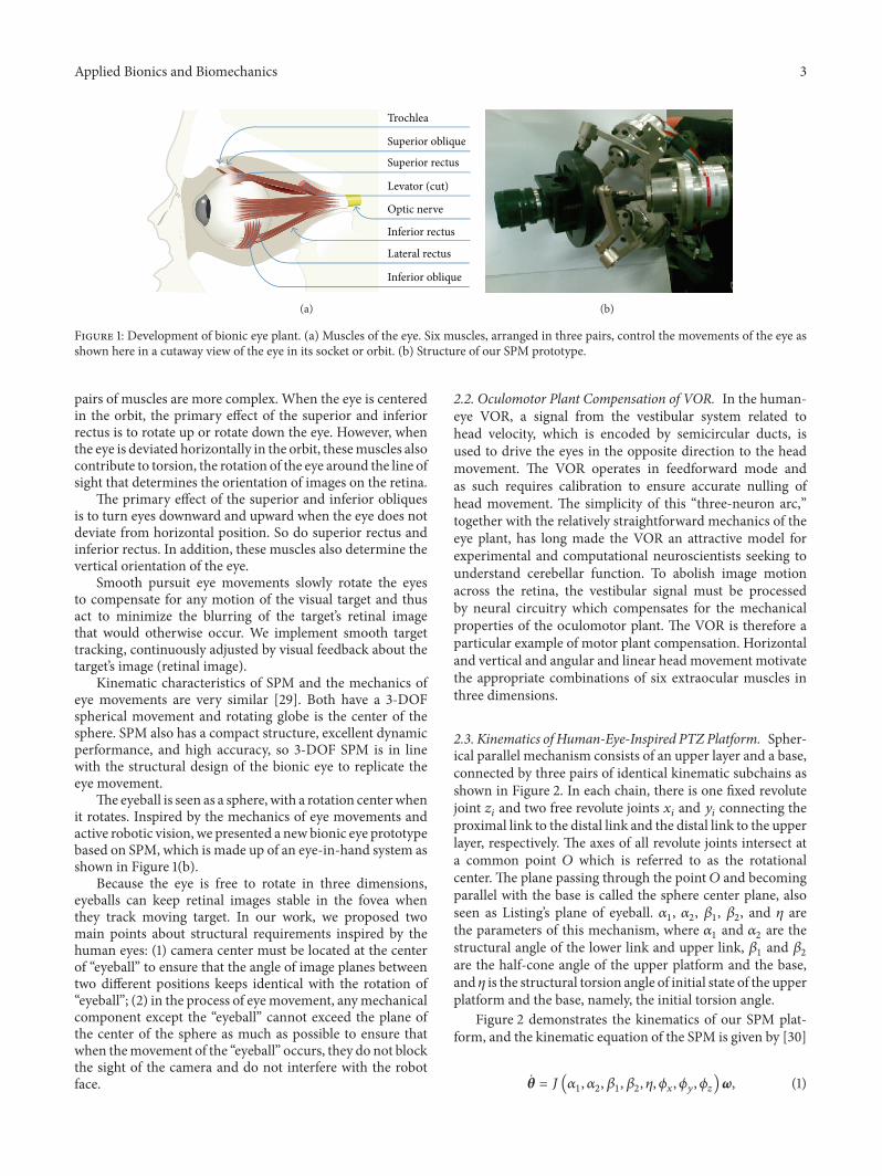
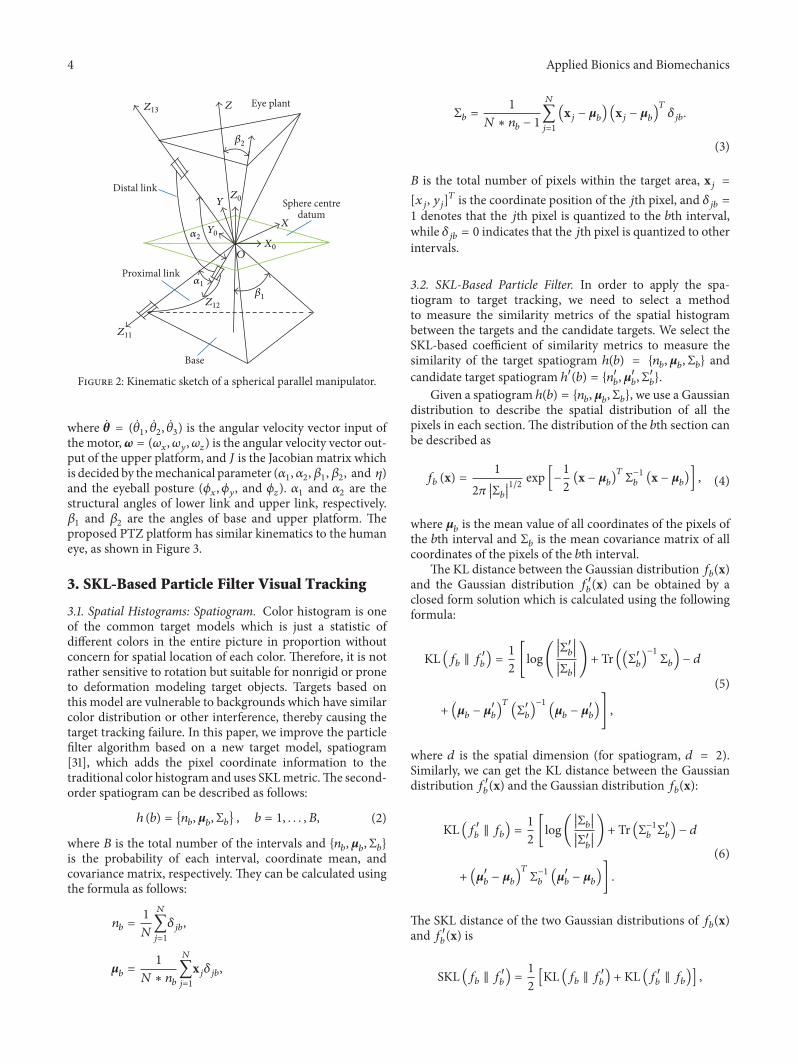
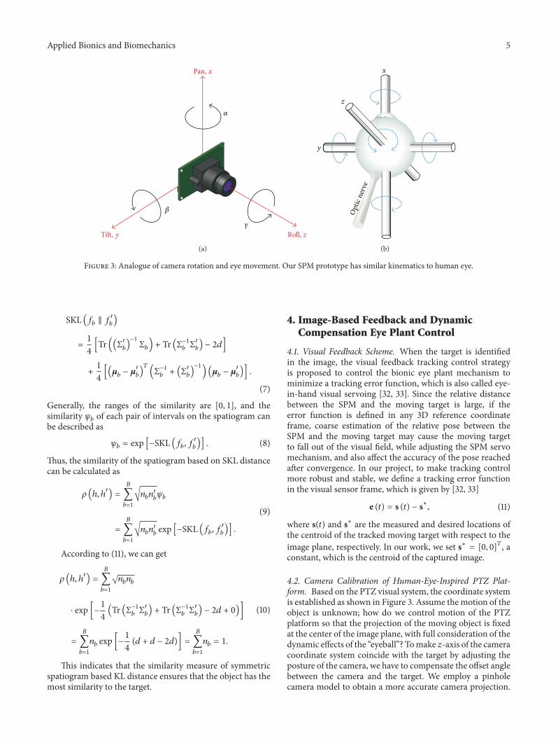
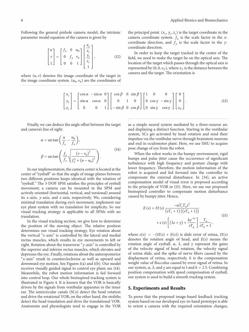
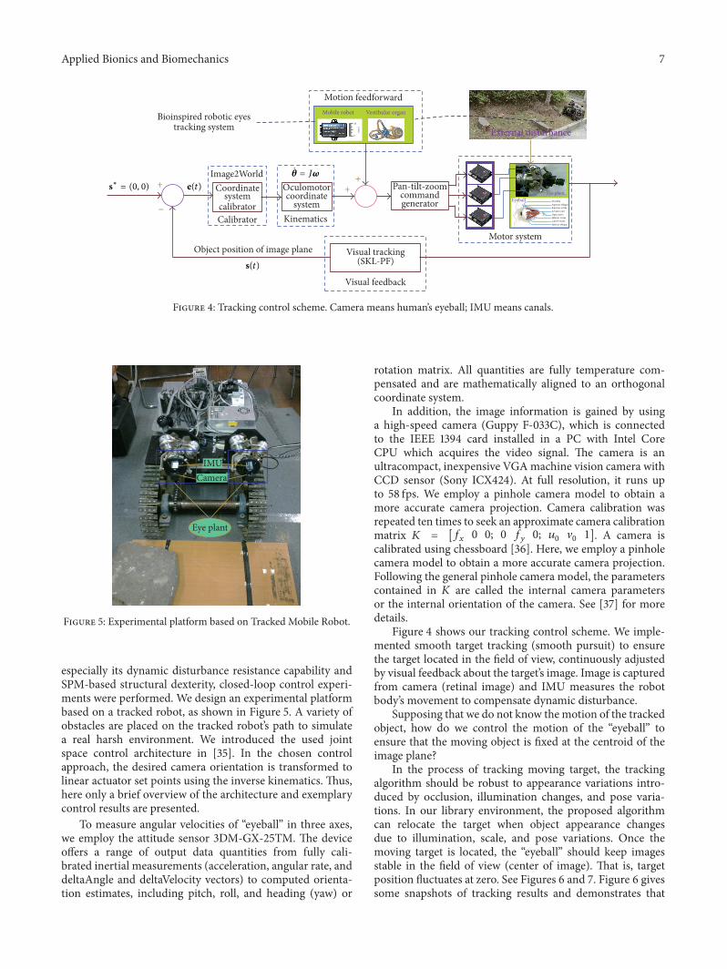
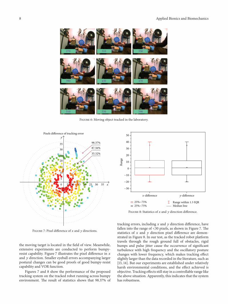
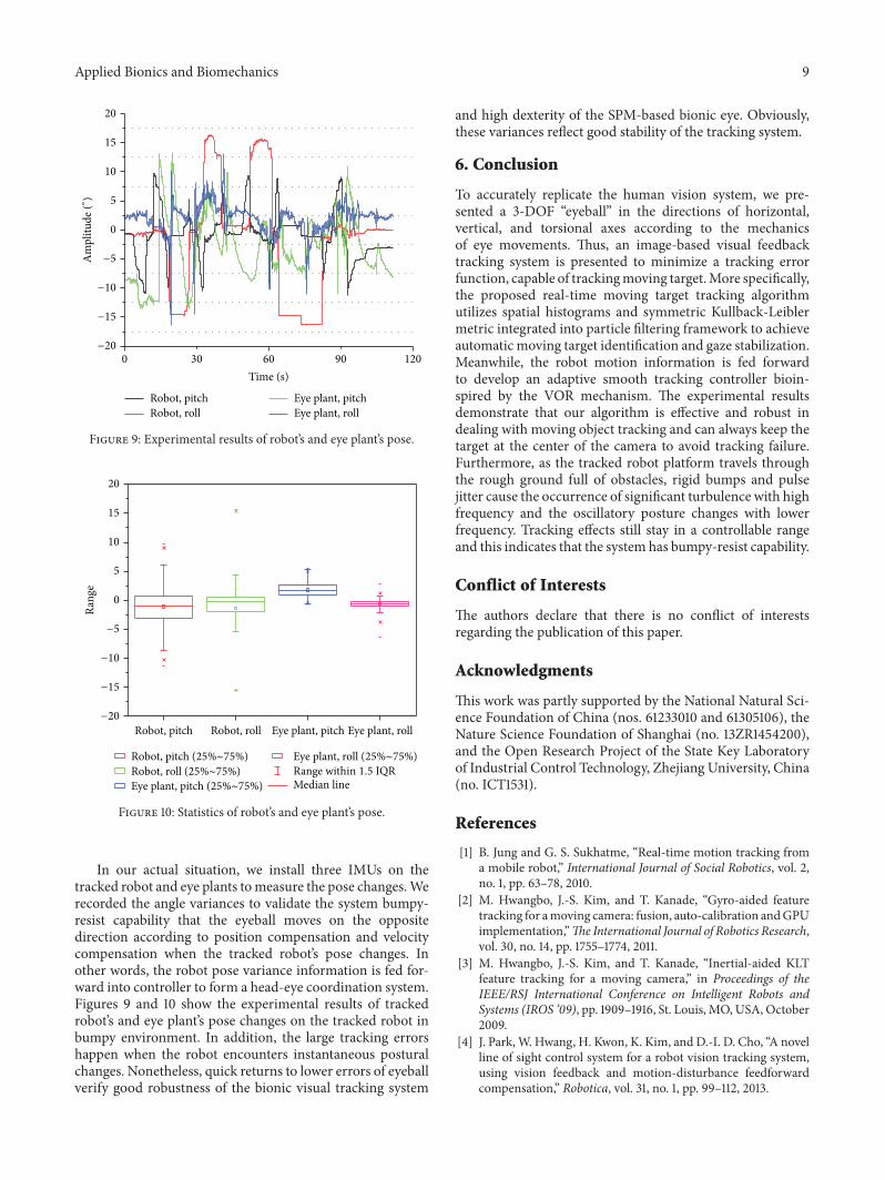
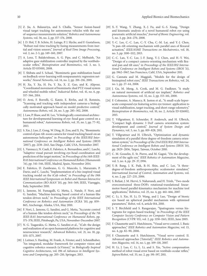

International Journal of
AerospaceEngineeringHindawi Publishing Corporationhttpwwwhindawicom Volume 2014
RoboticsJournal of
Hindawi Publishing Corporationhttpwwwhindawicom Volume 2014
Hindawi Publishing Corporationhttpwwwhindawicom Volume 2014
Active and Passive Electronic Components
Control Scienceand Engineering
Journal of
Hindawi Publishing Corporationhttpwwwhindawicom Volume 2014
International Journal of
RotatingMachinery
Hindawi Publishing Corporationhttpwwwhindawicom Volume 2014
Hindawi Publishing Corporation httpwwwhindawicom
Journal ofEngineeringVolume 2014
Submit your manuscripts athttpwwwhindawicom
VLSI Design
Hindawi Publishing Corporationhttpwwwhindawicom Volume 2014
Hindawi Publishing Corporationhttpwwwhindawicom Volume 2014
Shock and Vibration
Hindawi Publishing Corporationhttpwwwhindawicom Volume 2014
Civil EngineeringAdvances in
Acoustics and VibrationAdvances in
Hindawi Publishing Corporationhttpwwwhindawicom Volume 2014
Hindawi Publishing Corporationhttpwwwhindawicom Volume 2014
Electrical and Computer Engineering
Journal of
Advances inOptoElectronics
Hindawi Publishing Corporation httpwwwhindawicom
Volume 2014
The Scientific World JournalHindawi Publishing Corporation httpwwwhindawicom Volume 2014
SensorsJournal of
Hindawi Publishing Corporationhttpwwwhindawicom Volume 2014
Modelling amp Simulation in EngineeringHindawi Publishing Corporation httpwwwhindawicom Volume 2014
Hindawi Publishing Corporationhttpwwwhindawicom Volume 2014
Chemical EngineeringInternational Journal of Antennas and
Propagation
International Journal of
Hindawi Publishing Corporationhttpwwwhindawicom Volume 2014
Hindawi Publishing Corporationhttpwwwhindawicom Volume 2014
Navigation and Observation
International Journal of
Hindawi Publishing Corporationhttpwwwhindawicom Volume 2014
DistributedSensor Networks
International Journal of


![Research Article Symmetric Kullback-Leibler Metric Based ... › journals › abb › 2015 › 714572.pdfcompound eye (CurvACE) [ ] was endowed using similar micromovements to those](https://static.fdocuments.in/doc/165x107/60d12bd6d2b82f0253766c1c/research-article-symmetric-kullback-leibler-metric-based-a-journals-a-abb.jpg)


![Kullback-Leibler Penalized Sparse Discriminant Analysis ... · Victoria Peterson 1, Hugo Leonardo Ru ner1,2, and Ruben Daniel Spies3 ... arXiv:1608.06863v1 [cs.CV] 24 Aug 2016. we](https://static.fdocuments.in/doc/165x107/5f90eeeaac5613568f690762/kullback-leibler-penalized-sparse-discriminant-analysis-victoria-peterson-1.jpg)