
Research Article Shujuan Yang* Application of energy ...
11
Research Article Shujuan Yang* Application of energy dissipation and damping structure in the reinforcement of shear wall in concrete engineering https://doi.org/10.1515/phys-2020-0149 received March 06, 2020; accepted August 24, 2020 Abstract: In view of the problem of large earthquake displacement in the use of the original concrete engineering shear wall reinforcement method, the energy dissipation and damping structure is used to design the energy dissipation and damping structure reinforcement method in the concrete engineering shear wall. According to the design process of the set method, the anti-vibration coefficient of the concrete shear wall is tested. The energy dissipation structure is used to construct a shear damping wall, and the damper is added to the original shear wall. The concrete shear wall is strengthened by sticking steel technology. So far, the design of shear wall reinforcement method based on the energy dissipation structure has been completed. Compared with the original method, the displacement distance of this method is lower than that of the original method. In conclusion, the effect of shear wall reinforce- ment method based on the energy dissipation structure is better than that of the original method. Keywords: seismic reinforcement, concrete engineering, shear wall, interface 1 Introduction With the development of social economy, the use performance and function of some existing houses have changed, increasing the overall load on the existing houses. Some of the existing houses have increased the use area at the parts with larger storey height or the roof, or arranged at the concave and convex parts of the ground to meet the energy saving requirements [1]. Even some buildings cannot meet the existing load bearing capacity, they need to be strengthened. Affected by the earthquake, local training buildings need to be strength- ened in a small area. Therefore, the renovation and reinforcement of existing houses are increasing day by day. According to the development of the situation, architectural structural designers should be able to skillfully engage in the structural design of new buildings, and gradually be familiar with and master the transformation and reinforcement design of existing buildings [2]. With the rapid development of economy, the acceleration of urbanization, and the prosperity of construction industry, a large number of buildings have been built to meet the needs of people’s increasing material living standards. During this period, the number of buildings not only showed a blowout growth, but also constantly enriched and innovated in form and structure. However, with the passage of time, in these buildings gradually appear component aging, strength reduction, and other problems in the use stage, which have a great impact on the service performance of the structure, and the seismic capacity is significantly reduced [3]. According to statistics, at present, the urban housing area in China has exceeded 5 billion square meters, and more than half of them have been put into use for more than 40 years, which shows that the housing aging problem in China has become prominent [4]. In addition, due to improper design, construction defects, changes in the use of buildings, natural disasters, long-term acid, alkali, salt erosion or weath- ering, freeze–thaw cycle, and other reasons, the relia- bility of the structure will also be reduced, which cannot meet the requirements of seismic fortification, leaving a potential safety hazard. If these buildings are demol- ished and rebuilt, they will not only waste human, material, and financial resources, cause resource waste and environmental pollution, but also bring great inconvenience to people’s life and urban traffic. In view of this phenomenon, strengthening the building * Corresponding author: Shujuan Yang, Department of Architecture and Civil Engineering, Yantai Vocational College, Yantai, 264670, China, e-mail: [email protected] Open Physics 2020; 18: 631–641 Open Access. © 2020 Shujuan Yang, published by De Gruyter. This work is licensed under the Creative Commons Attribution 4.0 International License.
Transcript of Research Article Shujuan Yang* Application of energy ...
Research Article
Shujuan Yang*
Application of energy dissipation and dampingstructure in the reinforcement of shear wall inconcrete engineering
https://doi.org/10.1515/phys-2020-0149received March 06, 2020; accepted August 24, 2020
Abstract: In view of the problem of large earthquakedisplacement in the use of the original concreteengineering shear wall reinforcement method, theenergy dissipation and damping structure is used todesign the energy dissipation and damping structurereinforcement method in the concrete engineering shearwall. According to the design process of the set method,the anti-vibration coefficient of the concrete shear wall istested. The energy dissipation structure is used toconstruct a shear damping wall, and the damper isadded to the original shear wall. The concrete shear wallis strengthened by sticking steel technology. So far, thedesign of shear wall reinforcement method based on theenergy dissipation structure has been completed.Compared with the original method, the displacementdistance of this method is lower than that of the originalmethod. In conclusion, the effect of shear wall reinforce-ment method based on the energy dissipation structureis better than that of the original method.
Keywords: seismic reinforcement, concrete engineering,shear wall, interface
1 Introduction
With the development of social economy, the useperformance and function of some existing houseshave changed, increasing the overall load on the existinghouses. Some of the existing houses have increased theuse area at the parts with larger storey height or the roof,or arranged at the concave and convex parts of the
ground to meet the energy saving requirements [1]. Evensome buildings cannot meet the existing load bearingcapacity, they need to be strengthened. Affected by theearthquake, local training buildings need to be strength-ened in a small area. Therefore, the renovation andreinforcement of existing houses are increasing day byday. According to the development of the situation,architectural structural designers should be able toskillfully engage in the structural design of newbuildings, and gradually be familiar with and masterthe transformation and reinforcement design of existingbuildings [2]. With the rapid development of economy,the acceleration of urbanization, and the prosperity ofconstruction industry, a large number of buildings havebeen built to meet the needs of people’s increasingmaterial living standards. During this period, thenumber of buildings not only showed a blowout growth,but also constantly enriched and innovated in form andstructure. However, with the passage of time, in thesebuildings gradually appear component aging, strengthreduction, and other problems in the use stage, whichhave a great impact on the service performance of thestructure, and the seismic capacity is significantlyreduced [3]. According to statistics, at present, the urbanhousing area in China has exceeded 5 billion squaremeters, and more than half of them have been put intouse for more than 40 years, which shows that thehousing aging problem in China has become prominent[4]. In addition, due to improper design, constructiondefects, changes in the use of buildings, naturaldisasters, long-term acid, alkali, salt erosion or weath-ering, freeze–thaw cycle, and other reasons, the relia-bility of the structure will also be reduced, which cannotmeet the requirements of seismic fortification, leaving apotential safety hazard. If these buildings are demol-ished and rebuilt, they will not only waste human,material, and financial resources, cause resource wasteand environmental pollution, but also bring greatinconvenience to people’s life and urban traffic. Inview of this phenomenon, strengthening the building
* Corresponding author: Shujuan Yang, Department of Architectureand Civil Engineering, Yantai Vocational College, Yantai, 264670,China, e-mail: [email protected]
Open Physics 2020; 18: 631–641
Open Access. © 2020 Shujuan Yang, published by De Gruyter. This work is licensed under the Creative Commons Attribution 4.0International License.

shear wall has become the first choice to improve theservice life of concrete engineering.
Reference [5] puts forward the principle of distanceinteraction between particles in building mechanics. Inthe process of concrete engineering shear wall reinforce-ment, the relative function of shear wall balance isanalyzed. Through the study of the thermodynamics ofshear wall structure, the reinforcement of concreteengineering shear wall is completed, but the overalleffect of this method still needs to be further strength-ened. Reference [6] puts forward the limit evaluationmethod of high-strength concrete beam column reinfor-cement design. This method carries out experimentalresearch on 12 high-strength concrete buildings, ana-lyzes the different application degrees of the totalamount of longitudinal reinforcement and concretestrength, respectively, and obtains the accurate limitevaluation method of beam column reinforcement, butthe cost of this method is high and the overall efficiencyis low. In reference [7], the shear force of reinforcedconcrete wall is designed. Under the condition ofminimum shear reinforcement ratio, the yield strengthof shear reinforcement is limited to 420MPa. In order toclarify the influence of shear strength and minimumreinforcement ratio of reinforced concrete shear wallunder different reinforcement conditions, a cyclic lateralload test is carried out under different reinforcementconditions to complete the shear design of reinforcedconcrete. However, the whole process of this method iscomplex and its applicability needs to be furtherimproved.
Reinforced concrete shear wall is a kind of structuralcomponent which mainly bears the vertical and hor-izontal loads caused by wind or earthquake. It has goodlateral stiffness and seismic performance, so it is alsocalled seismic wall or wind wall. In the frame structuresystem, the problem of exposed beam and exposedcolumn often occurs, and the shear wall can avoid thisproblem, make the internal space of the building moreopen and beautiful, and improve the space utilizationrate, so that the shear wall can be widely used in multi-storey or high-rise buildings [8]. Shear wall is dividedinto four types: solid wall, small opening wall, joint wall,and wall frame. It is used to realize the seismic functionof concrete buildings. Compared with the seismicstrengthening of existing buildings, the seismic designof new buildings is simple and direct. On the basis of alarge number of studies on the seismic performance ofbuilding materials and structure details, the currentbuilding structure design code puts forward many strictmethods and regulations for the design of new buildings
according to the expected building functions. In thedesign of new buildings, engineers can select reason-able, economic, and effective structural forms accordingto the requirements of the use of buildings, so that theseismic performance of new buildings can be easilycontrolled [9].
2 Materials and methods
In view of the existing concrete engineering shear wallreinforcement method in use, the seismic capacity ispoor. The energy dissipation structure is used to improvethe shortcomings of the original method. Energydissipation is used to install energy dissipators (dam-pers) in the structure, artificially increase the structuraldamping, consume the vibration energy of the structureunder the earthquake, reduce the vibration response ofthe structure, and achieve the purpose of earthquakeresistance of the structure. The design mechanism of aconcrete engineering shear wall reinforcement method isas follows [10].
Generally speaking, the seismic reinforcement ofexisting buildings includes: the restoration of buildingsafter disasters, including earthquakes and fires; and thereinforcement of existing buildings. By adopting rein-forcement measures, the original state of the buildingcan be effectively restored, the seismic performance ofthe building can be improved, and the seismic responseof the building can be reduced. The shear wall rein-forcement of concrete engineering mainly includes:repairing the damaged parts, improving the stiffnessdistribution of the building, strengthening the existingstructure, setting the damping device, setting thevibration isolation device, and reducing the self-weightof the building. In this method design, the energydissipation structure will be used to strengthen theseismic coefficient of the shear wall (Figure 1).
2.1 Detection of anti-vibration coefficient ofthe concrete shear wall
In this design, in order to ensure the effectiveness andpertinence of the reinforcement part, the anti-vibrationcoefficient of the concrete shear wall is first tested. Theseismic evaluation of shear wall is a direct method to testthe current use of shear wall, determine the feasibility ofshear wall transformation scheme, and plan for the
632 Shujuan Yang

future use of the building. The existing seismic appraisalof a reinforced concrete structure needs to detectmultiple seismic factors of the structure. The compre-hensive seismic capacity analysis of the test results leadsto the appraisal conclusions, including: the rationality ofthe overall layout of the structure, the concrete strengthtest, the mechanical properties of the reinforcement andthe corrosion degree test, the component connectiontest, the component seismic bearing capacity test, etc.According to the current standard “standard for seismicevaluation of buildings” [11], the general steps forseismic evaluation of existing buildings are to checkthe original data of buildings, such as the calculationsheet of architectural design drawings and the comple-tion acceptance documents. If the data are not complete,the buildings to be evaluated shall be surveyed on site. Itis necessary to check whether the existing serviceconditions of the building are consistent with the designdocuments, the construction quality of the site survey,and the maintenance of the building, and find out thedefects of the building in terms of earthquake resistance.According to the characteristics of the structural type ofthe building, the on-site inspection shall be carried outfor the material strength, component reinforcement, andstructural layout of the building. According to the testresults and seismic bearing capacity analysis, the seismicevaluation report has to be made. If the appraised buildingconforms to the requirements of the standard for seismic
evaluation of buildings, the subsequent service life of thebuilding shall be stated and the handling method shall beproposed for the non-conformities. At present, there aremany common methods to determine the anti-vibrationcoefficient of a shear wall. In order to ensure the feasibilityof this design method, the method of comparing theadvantages and disadvantages of the measurementmethod will be used to obtain the form suitable forconcrete shear wall [12].
Through the above comparison results, in thisdesign, the ultrasonic-rebound method is used tocomplete the wall anti-vibration test. In the process ofreinforcement, the rebound instrument is used to dealwith the shear wall in the project according to the aboveset detection steps. In order to effectively control thedata in the detection and ensure its accuracy andoperability, a special rebound instrument is selected tocomplete the work in this detection. The specific modelof a rebound instrument is shown below (Figure 2).
The anti-vibration coefficient of shear wall is testedby the above instrument. The evaluation of anti-vibration coefficient of existing buildings is based onthe evaluation of anti-vibration measures and thecalculation of anti-vibration bearing capacity. Theidentification of anti-vibration measures includes thearrangement of anti-lateral force members, abruptchange of stiffness distribution, identification of struc-tural system, and strength detection of structural
Design of shear wall reinforcement method for concrete engineering based on energy dissipation structure
Detection of anti vibration coefficient of concrete shearwall Strengthening of concrete shear wall
Set the equipment
to beused
Calculationof wall internal
stress
Calculation of dynamic
elastic modulus of
wall
Reference
damper
Set damping
coefficient
Quote and stick steel technology
Calculation of damping
coefficient
Figure 1: Design framework of the shear wall reinforcement method for concrete engineering based on the energy dissipation structure.
Application of energy dissipation and damping structure 633

materials [13]. When the anti-vibration intensity is morethan six degrees, it is necessary to check the anti-vibration bearing capacity, and at least check the anti-vibration bearing capacity in two directions of the mainshaft. It is known that the strength of concrete isproportional to the elastic modulus when the type andproportion of concrete aggregate are fixed, while thepropagation speed of wave in the medium is related tothe elastic modulus and density, as shown in thefollowing formula.
≤
∂
A RCE
(1)
In the above formula, A is the design value of shear wallinternal force, R is the design value of shear wall bearingcapacity, and ∂CE is the adjustment coefficient of shearwall anti-vibration. Through the above formula, theoriginally measured data are processed. The anti-vibration coefficient of shear wall is calculated bycombining the processed data with ultrasonic method.
The ultrasonic method is used to measure thepropagation time of the wave in the concrete mediumby the method of sending and receiving two probes, thencalculate its velocity, and determine the concretestrength by the numerical curve. The specific calculationprocess is as follows [14].
=( − )
( − )( − )
V E μρ C μ
11 1 2
C (2)
In the above formula, EC is the dynamic modulus ofelasticity, ρ is the density, and μ is the Poisson’s ratio.The specific value of shear wall strength V can becalculated by the above formula. It should be noted thatwhen using the above formula to measure the measuringpoints, the measuring points of the shear wall shouldTa
ble1:
Com
pariso
nof
severalmetho
dsforthede
term
inationof
anti-vibration
coeffi
cien
tof
conc
rete
shea
rwall
Metho
dSco
peof
use
Conten
tde
term
ination
Adv
antage
Sho
rtco
ming
Rebo
und
Com
pres
sive
streng
than
dho
mog
eneity
Determinetheha
rdne
ssvalueof
thepo
sition
surface
Themetho
dis
simplean
dea
syto
operate
Themea
suring
position
canon
lybe
onthesu
rfaceof
thetest
piecewithlow
accu
racy
Ultraso
nic-rebo
und
Com
pres
sive
streng
thDeterminetheha
rdne
ssvalueof
thepo
sition
surfacean
dthe
prop
agationsp
eedof
theso
und
wavein
theco
ncrete
Themetho
dis
simple,
easy
toop
erate,
andha
shigh
precision
Com
plex
operation
Core
Com
pres
sive
streng
th,internal
defects
Pres
sure
resistan
ceof
core
sampledrilling
Highprecision
Dam
ageto
walls,rep
airrequ
ired
Pull-ou
tCom
pres
sive
streng
thPu
ll-ou
tforce
Highprecision
Theeq
uipm
entis
bulky,
caus
ing
damag
eto
thewall,which
need
sto
berepa
ired
Figure 2: Model and appearance of a rebound tester selected in thepaper.
634 Shujuan Yang

not be less than the average value of 10 pairs of speed,and the measuring points must avoid the reinforcementin the concrete, so as to avoid greatly affecting themeasurement results. The anti-vibration coefficient ofshear wall can be obtained from the above calculationresults and the measured value of the rebound instru-ment. In this method, the rebound instrument and theultrasonic instrument are used to work together tomeasure the rebound and wave velocity values of thesame test piece. Then with the adjustment coefficient ofdifferent materials, the measurement results are sub-stituted into the following formula to calculate the anti-vibration coefficient of the concrete shear wall of the testpiece. The specific formula is as follows.
= ( ) ( )f A V Rc b cec o o (3)
In the above formula, f cec is the anti-vibration coefficient
of shear wall, Vo is the ultrasonic velocity measurement,Ro is the rebound value of wall, and o b c, , is theconcrete strength. In the process of strength measure-ment, the rebound value and sound velocity valueshould be measured before the ultrasonic test. Basedon the layout of the test area, engineers shall select threeultrasonic test points in the test plane and then calculatethe average value of the sound velocity according to thefollowing formula.
=
+ +
V ly y y
31 2 3
(4)
In the above formula, V is the average value of ultrasonicwave, l measurement distance, and y y y, ,1 2 3 is the timevalue of three measurement points. The above formula isused to control the ultrasonic speed measurement.
2.2 Construction of a shear damping wallwith energy dissipation structure
In this method design, the damper is used to completethe design of energy dissipation and damping structureof concrete buildings. According to the characteristics ofconcrete, dampers are selected to realize the energydissipation and damping performance of shear walls. Inorder to ensure the effectiveness of reinforcement, aviscous damper is selected to complete the design. Theviscous damper can be divided into fluid resistance type(hydraulic cylinder type) and shear resistance typeaccording to the different damping methods of viscousmaterials. The shear resistance type can also be dividedinto (three-way) tubular viscous damper and viscousdamping wall, as shown in the figure below (Figure 3) [15].
According to the above classification, the viscousdamping wall is selected as the design basis of theenergy dissipation and damping structure. Viscous fluiddamper is mainly composed of steel, damping materials,and sealing materials. Due to the rustproof treatment ofsteel and the chemical stability of sealing materials, thedurability of a viscous fluid damper depends on thedurability of damping materials. A damping material isnot easy to age, and there is almost no change duringnormal use: under the action of cyclic stress, thecharacteristics of a damping material do not change,and its fatigue resistance is good; a damping material isextremely stable for ozone and ultraviolet, and itsweather resistance is good; a damping material doesnot undergo change when it is immersed in water, andits water resistance is excellent. Through the installation
Fluid Viscous Damper
Fluid damper
Single rod damperSingle rod damper
Shear damper
Three way damperviscous damping wall
Figure 3: Classification of viscous dampers.
Figure 4: Viscous damper.
Application of energy dissipation and damping structure 635

of dampers in shear wall joints, the energy dissipationand damping performance of shear wall is strengthened.The damper models selected in this paper are as follows(Figure 4).
The above dampers are used for energy dissipationand vibration reduction of shear walls. The locationoptimization of dampers is an important problem inenergy dissipation design. Its purpose is to use the leastnumber of dampers to make the structural systemachieve the corresponding damping objectives or evena better damping effect. Therefore, the selection ofoptimization objectives becomes particularly important.At present, the common objective control functions aremainly the maximum interfloor displacement angle,floor lateral displacement, absolute acceleration, andtheir weighted combination of the structure. Accordingto the characteristics of viscoelastic dampers, there arefive kinds of damper optimization design methods withdifferent objective control functions: Taking interlayerdisplacement as control function; taking control force ascontrol function; taking interlayer displacement andfloor lateral displacement as control function; takinginterlayer displacement and top floor displacement ascontrol function; and taking vibration mode as controlfunction. According to the relevant characteristics ofconcrete shear wall, in this design, interlayer displace-ment and top floor displacement are selected as thecontrol function in the design scheme of the damper.According to the given different damping, the optimaldamping is the optimal configuration when the optimalcontrol effect is obtained; through genetic algorithm, theoptimal damping is sought to reduce the total dampingwhen the seismic performance of the structure isbasically the same. Based on the theory of structuralcontrol, the optimal position with the control force as theobjective is studied from the two criteria of “safety” and“comfort”. It is concluded that the optimal position is atthe maximum displacement of the first mode when thevariance of the control force and the variance of thestructural response are the minimum.
According to the measured anti-vibration coefficientof shear wall, the damping coefficient of damper is setand applied to the reinforcement of shear wall. In thisdesign, the Maxwell model is used to set the dampingcoefficient of damping wall [16], which is a moreaccurate mechanical calculation model expressed bythe continuity of pure damping element and damper’sown stiffness. In this model, the damper has a strongdependence on the frequency. In this model, if we definethe damper’s own stiffness as a spring element, and itsdamping model can be made up of a pure damping
element and a spring element in series, then thedamping coefficient can be obtained through the datachanges before and after the deformation of the puredamping element and the spring element. If thedisplacements of damping element [17] and springelement are ∂ ( )t1 and ∂ ( )t2 , respectively, the relationshipcan be expressed as follows:
∂ ( ) + ∂ ( ) = ∂( )t t t1 2 (5)
∂ ( ) + ∂ ( ) = ∂( )Q t P t F to o1 2 (6)
The integration of the above two formulas is asfollows:
∂( ) + ∂( ) = ∂ ( )F t F t Q to 1I (7)
In the above formula, ∂( )F t is the output of the damper,Qo is the linear damping constant at zero frequency, Pois the stiffness coefficient of the damper itself, and I isthe relaxation time coefficient of the damper. Usingthe Fourier transform and Euler formula for the aboveformula, and making ∂( ) = ( ) ( )F ϖ P ϖ Q ϖo o , we can get thefollowing expression of the complex Maxwell model:
∂ ( ) + ∂ ( ) = ∂( )ϖ ϖ ϖ1 2 (8)
∂ ( ) = ∂ ( ) = ( )∂( )iF ϖ P ϖ Q ϖ ϖ1 2 o o (9)If the above two formulas are combined, they are:
( ) =∂ ( )
∂( )
=( )
+ ∂ ( )/∂ ( )
=( )
( ) + ( )
Q ϖ iF ϖϖ
iF ϖϖ ϖ
iF ϖQ ϖ iF ϖ
1o1
2 1
o
(10)
Through the calculation of the above formula, theenergy storage coefficient and energy dissipation coeffi-cient of the shear wall after the damper is installed can beobtained. The formula can be expressed as follows [18]:
( ) =∂ ( )
+ ∂ ( )
y ϖ Q ϖϖ11
o2
2 2 (11)
( ) =( )
+ ∂ ( )
y ϖ Q ϖϖ12
o2
2 2 (12)
Considering the damper–damping relationship,there are:
( ) = ( )℘( ) = ( )℘( )
( ) = ( )/℘( )= ( )
F ϖ Q ϖ ϖ Q ϖ ϖT ϖ F ϖ ϖ
Q ϖo oo (13)
Combining the above with the damper energydissipation coefficient ( )y ϖ2 , the damping coefficient ofthe damping wall after the energy dissipation structure is:
( ) =( )B ϖ Q ϖ
ϖo2 (14)
636 Shujuan Yang

The damping parameters of the damper used in the shearwall are controlled by the above formula and applied tothe concrete shear wall.
2.3 Strengthening of the concreteshear wall
Compared with the traditional structural strengtheningtechnology, this design uses the buckling brace reinfor-cement technology to install the buckling brace in thewall. The technology cannot damage the use function ofthe original structure, does not affect the size of thestructure space, and is easy to maintain. Compared withthe traditional reinforcement technology, the repair workafter a major earthquake is more simple and recyclable.Buckling restrained brace is a new seismic methoddeveloped in recent decades. The essence of the anti-seismic technology of buckling brace is to set thebuckling brace between the structural members. Whenan earthquake occurs, the buckling brace members yieldbefore the main structure, which plays the role of energydissipation and shock absorption, and can effectivelyreduce the damage of the main structure caused by theearthquake. As a result, the technology of buckling proofbrace has become the main direction of buildingreinforcement. In this project, it is difficult to ensurethe safety of the structure under a strong earthquake.The structure with buckling proof support has a greatenergy consumption capacity due to the buckling proofsupport. According to the domestic and foreign en-gineering examples, the cost of a buckling proof supporttechnology can be reduced by about 5–10% comparedwith the traditional reinforcement technology [19]. As itshows good economy, the project has adopted the buckling
support technology for reinforcement. The setting of abuckling brace used in this design is as follows (Figure 5).
In order to make the reinforcement part play a betterrole and put into use more quickly, the selection ofreinforcement materials is also very important. In orderto reduce the size and material use, high-strength steelcan be used. Considering the bonding of the combinationsurface of reinforcement and the integrity of thereinforcement components, when selecting materials tomake concrete, the raw materials with high strength,small shrinkage, and good bonding with the originalcomponents are used. In addition to adding dampersand buckling brace devices, the shear wall is strength-ened by sticking steel. The load-carrying capacity of themembers is enhanced by sticking the 2–6mm thick steelsheet on the surface of the concrete structure with acertain adhesive strength [20]. The construction process
A3 A2 A1 A2 A3
Figure 5: Design drawing of a buckling proof supporting apparatus.
Figure 6: Results of shear wall reinforcement with steel. (a) Designresults of sticking steel method. (b) Wall structure after pastingsteel.
Application of energy dissipation and damping structure 637

of this reinforcement method is simple and generallyused to strengthen the flexural and tensile members. Thestructural adhesive used has strict shear and tensilestrength, which can combine the strength of steel plateand concrete as a whole to resist the load. The shear wallstructure after sticking steel is as follows (Figure 6).
The glued steel plate and the coated structuraladhesive are exposed to the air. If the anti-corrosion andmaintenance measures are not carried out in time, thebearing capacity of the steel plate will be greatlyreduced, and the structural adhesive will lose itsadhesion. It is necessary to set the protective measuresas general application of waterproof materials and apply15–20mm M15 cement mortar to complete the reinforce-ment process [21,22]. Combining the above settings withthe energy dissipation structure, the design of a shearwall reinforcement method based on the energy dissipa-tion structure is completed.
3 Simulation experiment
In order to verify the effect of the method in this paper,the simulation experiment is conducted to obtain theresults of the comparison between the original methodand the design method in this paper. Many laws in thefield of engineering are often dug out from some specificand special phenomena: first, from the phenomenon,through the corresponding logical deduction and theo-retical analysis, to form a certain theoretical basis, thenoften use the finite element and other numericalsimulation methods to verify the relevant laws, whilefurther verification often needs to be carried out throughthe design of relevant tests, and then get more practicalresults. The design of this experiment is to further verifyand study the influence of regularity of the designmethod in this paper.
3.1 Experimental preparation
Considering that the viscous damper used in this paperis a velocity-dependent damper, and its normal workingfrequency is usually between 1 and 3 HZ, it is not allowedto use any general simulation experimental equipmentor conduct any static test. It is better to use the dynamicloading test with a dynamic control system. Therefore,the simulation seismic vibration table is selected to addthe seismic wave and sine wave to the concreteexperimental sample. For the load test, the basicparameters of the vibration table are shown in the tablebelow (Tables 1–3).
By using the above platform as the basic platform ofthis simulation experiment, through setting the relevantexperimental instruments to connect with the platform,we need to complete the component work of thecomplete experimental platform. In this experiment,the effect of earthquake on the shear wall of a concretestructure is simulated by an electronic tensile instru-ment, and the instruments used in the experiment are asfollows (Figure 7).
By using the above-mentioned instruments, thesimulation experiments are carried out on the experi-mental specimens after the original reinforcementmethod and the design reinforcement method in thispaper, and the seismic effects of the experimentalspecimens after the original method and the designmethod in this paper are compared.
3.2 Experimental specimen design
For the purpose of this experiment, the correspondingconcrete shear wall model is made. The size andreinforcement of the test piece are determined accordingto the requirements of the “code for design of concrete
Table 2: Parameters of experimental simulation platform
Item number Project Basic parameters
1 Platform size 5 m × 5m2 Maximum load capacity 20 T3 Direction of vibration Two-way three degrees of freedom4 Vibration waveform Various regular waves, random waves, and simulated seismic waves5 Peak acceleration 0.2 g6 Peak velocity 1,000mm/s7 Displacement peak value 150mm8 Maximum frequency 0.2 Hz9 Minimum frequency 150 Hz
638 Shujuan Yang

structure reinforcement” and the “code for design ofconcrete structure,” combined with the conditions of testequipment in the simulation laboratory. The model testpiece is composed of a base beam, wall, and loadingbeam. The height from the top of loading beam to thebottom of foundation beam is 1,500mm. The height ofloading beam is 200mm, the height of base beam is400mm, the height of wall is 900mm, the section lengthof wall limb is 800mm, the thickness of unreinforced wallis 70mm, and the total thickness of reinforced wall is140mm. The specific section size and reinforcementparameters of a shear wall model are as follows (Figure 8).
According to the above parameters as the designbasis of the experimental samples, in order to ensure theuniformity of the experimental process, the concrete and
steel bars used in the experiment are set to complete thedesign process of the shear wall on the basis of a certainproportion. The production processes are: steel proces-sing, strain gauge pasting, steel binding, skeletonproduction, formwork installation, concrete pouring,specimen maintenance, reinforcement treatment, andreinforcement specimen maintenance. Each constructionprocedure shall be carried out in strict accordance withthe code for construction of concrete structures(GB50666-2011), so as to ensure the quality of testpieces. The concrete proportions are as follows.
Due to the limited experimental conditions, in theprocess of the experiment, C35 concrete strengthmaterial is used as the basic part of the experimentalsample, and the proportion set above is used to completethe production of the experimental sample. In thisexperiment, the number of simulated earthquake in-tensity experiments is set to 30, and the intensity of eachearthquake increases by 5% compared with the previousexperiment. The displacements of the experimentalspecimen after using the design method and the originalstructure method are compared.
The parameters of seismic simulation are designedas follows: the shear wall load is 2.5 kn/m2, the seismicgrade of shear wall is grade 8, the peak value of basicseismic acceleration is 0.2 g, and the characteristicperiod is 0.45 s.
3.3 Analysis of experimental results
According to the above test settings, the displacementdata of the strengthened test pieces are obtained fromthe structural laboratory, and the comparison resultsbetween the proposed method and the reference [5]method are shown in Table 4.
According to the above test data, the reinforcementeffect of the proposed method is obviously better than
Figure 7: Electronic universal testing machine.
Figure 8: Experimental sample design results.
Table 3: Setting of concrete strength of an experimental specimen
Strength grade C30 C35 C40 C45 C50
Water–binder ratio 0.65 0.60 0.55 0.51 0.45Cement 170 185 190 220 270Mineral powder 66 68 72 80 100Powdered carbon ash 28 32 34 35 40Water 180 175 170 165 165Sand 891 863 820 745 637Stone 1,100 1,115 1,120 1,134 1,160Water reducing agent 1.2 1.35 1.55 2.15 1.75
Application of energy dissipation and damping structure 639
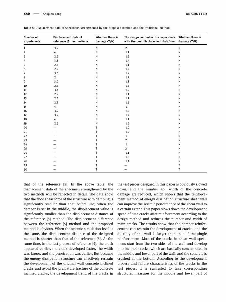
that of the reference [5]. In the above table, thedisplacement data of the specimen strengthened by thetwo methods will be reflected in detail. The data showthat the floor shear force of the structure with damping issignificantly smaller than that before use; when thedamper is set in the middle, the displacement value issignificantly smaller than the displacement distance ofthe reference [5] method. The displacement differencebetween the reference [5] method and the proposedmethod is obvious. When the seismic simulation level isthe same, the displacement distance of the designedmethod is shorter than that of the reference [5]. At thesame time, in the test process of reference [5], the crackappeared earlier, the crack developed faster, the widthwas larger, and the penetration was earlier. But becausethe energy dissipation structure can effectively restrainthe development of the original wall concrete inclinedcracks and avoid the premature fracture of the concreteinclined cracks, the development trend of the cracks in
the test pieces designed in this paper is obviously sloweddown, and the number and width of the concretedamage are reduced, which shows that the reinforce-ment method of energy dissipation structure shear wallcan improve the seismic performance of the shear wall toa certain extent. This paper slows down the developmentspeed of time cracks after reinforcement according to thedesign method and reduces the number and width ofmain cracks. The results show that the damper reinfor-cement can restrain the development of cracks, and theductility of the wall is larger than that of the singlereinforcement. Most of the cracks in shear wall speci-mens start from the two sides of the wall and developinto inclined cracks, which are basically concentrated inthe middle and lower part of the wall, and the concrete iscrushed at the bottom. According to the developmentprocess and failure characteristics of the cracks in thetest pieces, it is suggested to take correspondingstructural measures for the middle and lower part of
Table 4: Displacement data of specimens strengthened by the proposed method and the traditional method
Number ofexperiments
Displacement data ofreference [5] method/mm
Whether there isdamage (Y/N)
The design method in this paper dealswith the post displacement data/mm
Whether there isdamage (Y/N)
1 3.2 N 2 N2 4 N 1.1 N3 2.3 N 1.3 N4 3.5 N 1.4 N5 2.6 N 1.1 N6 2.7 N 1.7 N7 3.6 N 1.9 N8 2 N 1.7 N9 3.2 N 1.3 N10 2.3 N 1.3 N11 3.4 N 1.2 N12 2.7 N 1.1 N13 2.5 N 1.1 N14 2.9 N 1.5 N15 4 N 1 N16 3.9 N 1.5 N17 3.2 N 1.7 N18 4 N 1.1 N19 2.3 N 1.2 N20 — T 1.9 N21 — T 1.2 N22 — T 1 N23 — T 2 N24 — T 1 N25 — T 2 N26 — T 1.1 N27 — T 1.3 N28 — T 1.4 N29 — T — T30 — T — T
640 Shujuan Yang

the wall in the process of reinforcement. In conclusion,this design method is superior to the reference [5] designmethod.
4 Conclusions
In order to improve the safety of concrete buildings, thispaper studies the important problems of energy dissipa-tion and damping structure in the application ofconcrete shear wall reinforcement through theoreticalanalysis, numerical simulation, shaking table test ofearthquake simulation, and engineering examples. Thefollowing conclusions are proved by theory and experi-ment. This method shows high accuracy in the analysisof concrete shear wall reinforcement. First, the influenceof shear wall on building safety is analyzed in detail andthen the reinforcement method of shear wall is designed.The experimental results show that, compared with thetraditional method, the energy dissipation structure caneffectively inhibit the development of the original wallconcrete diagonal cracks and avoid the prematurefracture of the concrete diagonal cracks. In futureresearch, the design method will be improved to ensurean advanced and reasonable method.
References
[1] Ashraf T, Ranaiefar M, Khatri S, Kavosi J, Gardea F, Glaz B,et al. Carbon nanotubes within polymer matrix can synergis-tically enhance mechanical energy dissipation.Nanotechnology. 2018;29(11):115704.
[2] Krymsky GF. Energy dissipation in a medium with turbulentviscosity and the hill vortex. Doklady Phys.2019;64(6):269–70.
[3] Rashahmadi S, Meguid SA. Modeling size-dependent ther-moelastic energy dissipation of graphene nanoresonatorsusing nonlocal elasticity theory. Acta Mech.2019;230(3):771–85.
[4] Bauer A, Wegt S, Bopp M, Jakirlic S, Tropea C, Krafft AJ, et al.Comparison of wall shear stress estimates obtained bylaser Doppler velocimetry, magnetic resonanceimaging and numerical simulations. Exp Fluids.2019;60(7):1–16.
[5] Frommer F, Hanke M, Jansen S. A note on the uniquenessresult for the inverse Henderson problem. J Math Phys.2019;60(9):093303.
[6] Aguilar G, Villamizar S, Ramirez. JA. Evaluation of shearreinforcement design limits in high-strength concrete beams.Aci Struct J. 2018;115(2):401–14.
[7] Baek J-W, Park H-G, Choi K-K, Seo M, Chung L. Minimum shearreinforcement of slender walls with grade 500MPa (72.5 ksi)reinforcing bars. Aci Struct J. 2018;115(3):225–31.
[8] Bellizzi S, Chung K-W, Sampaio R. Response regimes of alinear oscillator with a nonlinear energy sink involving anactive damper with delay. Nonlinear Dyn.2019;97(2):1667–84.
[9] Vikash P, Prasad P, Dhrubaditya M. Clustering and energyspectra in two-dimensional dusty gas turbulence. Phys Rev E.2019;100(1):013114.
[10] Sessa S, Marmo F, Vaiana N, Rosati L. Probabilistic assess-ment of axial force–biaxial bending capacity domains ofreinforced concrete sections. Meccanica. 2019;54(9):1451–69.
[11] Claudia L, Burdick Jason A. Engineering stem and stromal celltherapies for musculoskeletal tissue repair. Cell Stem Cell.2018;22(3):325–39.
[12] Baleanu D, Fernandez A, Akgül A. On a fractional operatorcombining proportional and classical differintegrals.Mathematics. 2020;8(3):360.
[13] Patra A, Saha Ray S. Analysis for fin efficiency withtemperature-dependent thermal conductivity of fractionalorder energy balance equation using HPST method. Alex Eng J.2016;55(1):77–85.
[14] Takahisa M, Kentarou M, Ryota K, Otsuki K, Yuhao J,Fujisawa R, et al. Arousal from tonic immobility by vibrationstimulus. Behav Genetics. 2019;49(5):478–83.
[15] Pakoksung K, Suppasri A, Imamura F, Athanasius C, Omang A,Muhari A. Simulation of the submarine landslide tsunami on28 september 2018 in Palu Bay, Sulawesi Island, Indonesia,using a two-layer model. Pure Appl Geophys.2019;176(8):3323–50.
[16] Han YC. Case study of slope deterioration characteristics:simbal landslide, Salt Range, Pakistan. Environ Earth Sci.2019;78(10):1–9.
[17] Belyaev Aleksey V. Long ligands reinforce biological adhesionunder shear flow. Phys Rev E. 2018;97(4-1):042407.
[18] Al Kaissi A, Chehida FB, Grill F, Ganger R, Kircher SG. Turningthe backbone into an ankylosed concrete-like structure: casereport. Medicine. 2018;97(15):e0278.
[19] Akyildiz FT, Vajravelu K. Galerkin-Chebyshev pseudo spectralmethod and a split step new approach for a class of twodimensional semi-linear parabolic equations of second order.Appl Math Nonlinear Sci. 2018;3:255–64.
[20] Devaki P, Sreenadh S, Vajravelu K, Prasad KV, Vaidya H. Wallproperties and slip consequences on peristaltic transport of acasson liquid in a flexible channel with heat transfer. ApplMath Nonlinear Sci. 2018;3:277–90.
[21] Khalique CM, Mhlanga IE. Travelling waves and conservationlaws of a (2 + 1)-dimensional coupling system with Korteweg-de Vries equation. Appl Math Nonlinear Sci. 2018;3:241–54.
[22] Lokesha V, Shruti R, Deepika T. Reckoning of the dissimilartopological indices of human liver. Appl Math Nonlinear Sci.2018;3:265–76.
Application of energy dissipation and damping structure 641