Research Article Shape Optimization of NREL S809 Airfoil ...
14
Research Article Shape Optimization of NREL S809 Airfoil for Wind Turbine Blades Using a Multiobjective Genetic Algorithm Yilei He and Ramesh K. Agarwal Department of Mechanical Engineering and Materials Science, Washington University in St. Louis, St. Louis, MO 63130, USA Correspondence should be addressed to Ramesh K. Agarwal; [email protected] Received 27 February 2014; Revised 9 July 2014; Accepted 23 July 2014; Published 9 September 2014 Academic Editor: R. Ganguli Copyright © 2014 Y. He and R. K. Agarwal. is is an open access article distributed under the Creative Commons Attribution License, which permits unrestricted use, distribution, and reproduction in any medium, provided the original work is properly cited. e goal of this paper is to employ a multiobjective genetic algorithm (MOGA) to optimize the shape of a well-known wind turbine airfoil S809 to improve its liſt and drag characteristics, in particular to achieve two objectives, that is, to increase its liſt and its liſt to drag ratio. e commercially available soſtware FLUENT is employed to calculate the flow field on an adaptive structured mesh using the Reynolds-Averaged Navier-Stokes (RANS) equations in conjunction with a two-equation − SST turbulence model. e results show significant improvement in both liſt coefficient and liſt to drag ratio of the optimized airfoil compared to the original S809 airfoil. In addition, MOGA results are in close agreement with those obtained by the adjoint-based optimization technique. 1. Introduction With recent emphasis on emission-free renewable energy, wind energy has taken a center stage in recent years with exponential growth in deployment of wind-turbines world- wide. Among wind-turbines, horizontal-axis-wind-turbines (HAWTs) are mostly deployed for power generation in Megawatt range. It is well established that the power gen- erated by a HAWT is a function of the number of blades, the / of the blade airfoil section, and the tip speed ratio (= rotational speed of the blade at tip/wind speed in free stream). us, one of the goals of the design of a wind turbine blade is to maximize its / . As a result, there has been significant effort devoted in recent years to shape optimization of wind turbine blade to achieve high / . In last two decades, aerodynamic shape optimization has become an important tool in aircraſt design [1–4]. e focus of this paper is on the aerodynamic shape optimization of airfoil sections used in wind turbine blades since they affect their aerodynamic performance which in turn influences the amount of power a wind turbine can generate [5]. In modern wind-turbines, thick airfoils such as NACA- 63XXX and NACA-64XXX are frequently used; however, new airfoil families are increasingly being developed because of multiple requirements of aerodynamics performance at rated power conditions and off-rated power conditions as well as strong structural properties [6]. National Renewable Energy Laboratory (NREL) has developed a family of airfoils for HAWT applications [7] since 1984. e present paper focuses on the optimization of most well-known NREL airfoil, known as the S809 airfoil. is airfoil is 21% thick laminar flow airfoil whose design and experimental results are given in [8]. NREL Phase II, Phase III, and Phase VI HAWT blades are composed of S809 airfoil from root to tip [9]. Under class 3 to 4 wind conditions, S809 is subjected to low Mach number (almost incompressible) flow with Reynolds numbers in the range of one to two million. Laminar separation can occur on the suction surface for angles of attack ranging from zero to 5.13 degrees. Turbulent trailing edge separation occurs when angle of attack increases [10]. is paper presents shape optimization of S809 airfoil using a multiobjective genetic algorithm (MOGA). e com- mercially available soſtware FLUENT is used for calculation of the flow field using the Reynolds-Averaged Navier-Stokes (RANS) equations in conjunction with a two-equation − SST turbulence model. Using MOGA, globally optimal S809 airfoil shape is obtained which maximizes both and / for a given wind speed, rotational speed, and pitch setting. e results show that the aerodynamics characteristics of Hindawi Publishing Corporation International Journal of Aerospace Engineering Volume 2014, Article ID 864210, 13 pages http://dx.doi.org/10.1155/2014/864210
Transcript of Research Article Shape Optimization of NREL S809 Airfoil ...

Research ArticleShape Optimization of NREL S809 Airfoil for Wind TurbineBlades Using a Multiobjective Genetic Algorithm
Yilei He and Ramesh K Agarwal
Department of Mechanical Engineering and Materials Science Washington University in St Louis St Louis MO 63130 USA
Correspondence should be addressed to Ramesh K Agarwal rkawustledu
Received 27 February 2014 Revised 9 July 2014 Accepted 23 July 2014 Published 9 September 2014
Academic Editor R Ganguli
Copyright copy 2014 Y He and R K Agarwal This is an open access article distributed under the Creative Commons AttributionLicense which permits unrestricted use distribution and reproduction in any medium provided the original work is properlycited
The goal of this paper is to employ amultiobjective genetic algorithm (MOGA) to optimize the shape of a well-known wind turbineairfoil S809 to improve its lift and drag characteristics in particular to achieve two objectives that is to increase its lift and its liftto drag ratio The commercially available software FLUENT is employed to calculate the flow field on an adaptive structured meshusing the Reynolds-AveragedNavier-Stokes (RANS) equations in conjunctionwith a two-equation 119896minus120596 SST turbulencemodelTheresults show significant improvement in both lift coefficient and lift to drag ratio of the optimized airfoil compared to the originalS809 airfoil In addition MOGA results are in close agreement with those obtained by the adjoint-based optimization technique
1 Introduction
With recent emphasis on emission-free renewable energywind energy has taken a center stage in recent years withexponential growth in deployment of wind-turbines world-wide Among wind-turbines horizontal-axis-wind-turbines(HAWTs) are mostly deployed for power generation inMegawatt range It is well established that the power gen-erated by a HAWT is a function of the number of bladesthe 119862119897119862119889 of the blade airfoil section and the tip speedratio 120582 (= rotational speed of the blade at tipwind speedin free stream) Thus one of the goals of the design of awind turbine blade is to maximize its 119862119897119862119889 As a resultthere has been significant effort devoted in recent years toshape optimization of wind turbine blade to achieve high119862119897119862119889 In last two decades aerodynamic shape optimizationhas become an important tool in aircraft design [1ndash4] Thefocus of this paper is on the aerodynamic shape optimizationof airfoil sections used inwind turbine blades since they affecttheir aerodynamic performance which in turn influencesthe amount of power a wind turbine can generate [5]In modern wind-turbines thick airfoils such as NACA-63XXX and NACA-64XXX are frequently used howevernew airfoil families are increasingly being developed becauseof multiple requirements of aerodynamics performance at
rated power conditions and off-rated power conditions aswell as strong structural properties [6] National RenewableEnergy Laboratory (NREL) has developed a family of airfoilsfor HAWT applications [7] since 1984
The present paper focuses on the optimization of mostwell-known NREL airfoil known as the S809 airfoil Thisairfoil is 21 thick laminar flow airfoil whose design andexperimental results are given in [8] NREL Phase II PhaseIII and Phase VI HAWT blades are composed of S809 airfoilfrom root to tip [9] Under class 3 to 4 wind conditions S809is subjected to low Mach number (almost incompressible)flow with Reynolds numbers in the range of one to twomillion Laminar separation can occur on the suction surfacefor angles of attack ranging from zero to 513 degreesTurbulent trailing edge separation occurs when angle ofattack increases [10]
This paper presents shape optimization of S809 airfoilusing a multiobjective genetic algorithm (MOGA)The com-mercially available software FLUENT is used for calculationof the flow field using the Reynolds-Averaged Navier-Stokes(RANS) equations in conjunction with a two-equation 119896 minus 120596SST turbulence model Using MOGA globally optimal S809airfoil shape is obtained which maximizes both 119862119897 and 119862119897119862119889for a given wind speed rotational speed and pitch settingThe results show that the aerodynamics characteristics of
Hindawi Publishing CorporationInternational Journal of Aerospace EngineeringVolume 2014 Article ID 864210 13 pageshttpdxdoiorg1011552014864210
2 International Journal of Aerospace Engineering
optimized S809 are significantly improved For the purposeof validation the results are compared with those obtained byRitlop and Nadarajah [10] using the adjoint equation-basedoptimization method
2 Brief Description of Genetic Algorithm andAirfoil Parameterization
21 Single Objective Genetic Algorithm (SOGA) Geneticalgorithms are a class of stochastic optimization algorithmsinspired by the biological evolution InGA a set or generationof input vectors called individuals is iterated over succes-sively combining traits (aspects) of the best individuals untila convergence in the objective values (namely 119862119897 or 119862119897119862119889) isachieved In the context of the present paper the individualsare airfoils which are generated in each generation of GAThese airfoils in a given generation are randomly generatedwith some constraints so that their thickness camber andother geometric properties do not vary a great deal from theoriginal S809 airfoil The population of airfoils in a givengeneration is selected by the user a population of 20 airfoils isselected in this work Execution of GA employs the followingsteps [11 12]
(1) Initialization randomly create 119873 individuals (air-foils)
(2) Evaluation evaluate the fitness of each individual (air-foil) by calculating the fitness or objective function(eg lift coefficient or lift to drag ratio)
(3) Natural selection remove a subset of the individualsOften the individuals that have the lowest fitnessvalue are removed although culling the removingof those individuals with similar fitness is sometimesperformed
(4) Reproduction pick pairs of individuals to producean offspring This is often done by roulette wheelsampling that is the probability of selecting someindividual ℎ119894 for reproduction is given by
119875 [ℎ119894] =fitness (ℎ119894)
sum119895fitness (ℎ119895)
(1)
A crossover function is then performed to produce theoffspring Generally crossover is implemented by choosinga crossover point on each individual and swapping alleles orvector elements at this point as illustrated in Figure 1
(5) Mutation randomly alter some small percentage ofthe population
(6) Check for convergence if the solution has convergedreturn the best individual observed If the solutionhas not yet converged label the new generation as thecurrent generation and go to step 2 Convergence isachieved after a certain number of generations whenthe fitness value does not change for a number ofconsecutive generations (generally 3 to 5)
x11
x11
x21
x21
x22
x22
x23
x23
x12
x12
x13
x13
x1nminus2
x1nminus2
x2nminus2
x2nminus2
x2nminus1
x2nminus1
x1nminus1
x1nminus1
x1n
x1n
x2n
x2n
middot middot middot
middot middot middot
middot middot middot
middot middot middot
Figure 1 Illustration of the general crossover function in GA
22 Multiobjective Genetic Algorithm (MOGA) For manydesign problems it is desirable to achieve if possible simul-taneous optimization of multiple objectives [13]These objec-tives however are usually conflicting preventing simultane-ous optimization of each objective [14] Therefore insteadof searching for a single optimal solution a multiobjectivegenetic algorithm (MOGA) is necessary to find a set ofoptimal solutions (generally known as the set of Pareto-optimal solutions) A solution belongs to the Pareto set ifthere is no other solution that can improve at least one ofthe objectives without degrading any other objective ForPareto-optimal solutions any individual inside the Pareto setdominates any individual outside the set while any individualin the set is not dominated by another individual in thesolution set An individual dominating another individual inthe Pareto sense means that this individual is either betterthan or the same as the other individual for all objectives andat least there is one objective or fitness function for whichthis individual is strictly better than the other individualA solution is said to be Pareto optimal if and only if theredoes not exist another solution that dominates it The set ofall Pareto- optimal solutions is called the Pareto-optimal setThe MOGA used to find the Pareto-optimal solutions to theairfoil optimization problem in this study is widely knownas NSGA-II It has the following three features (1) it usesan elitist principle (2) it uses an explicit diversity preservingmechanism and (3) it emphasizes nondominated solutions ina population [15] The basic philosophy behind the NSGA-IIalgorithm is as follows
First the population is initialized based on the con-straints The population is then sorted based on nondomina-tion into various fronts the first front being completely thenondominant set in the current population and the secondfront being dominated by the individuals in the first frontonly and so on for the other fronts Individuals (airfoils) ineach front are assigned rank (fitness) values based on the frontto which they belong Individuals in first front are assigned
International Journal of Aerospace Engineering 3
a given fitness value and individuals in the second front areassigned another fitness value and so on In addition to thefitness value a new parameter called crowding distance iscalculated for each individual The crowding distance is ameasure of how close an individual is to its neighbors Largeaverage crowding distance usually results in better diversityin the population Parents are selected from the populationby using binary tournament selection based on the rank andthe crowding distance An individual selected in the rank islesser than the other if the crowding distance is greater thanthe other The selected population generates offsprings fromcrossover and mutation operators The population with thecurrent offsprings is sorted again based on nondominationand only the best 119873 individuals are selected where 119873 isthe population size The selection is based on rank and onthe crowding distance on the last front The implementationprocedure of NSGA-II is briefly as follows [16]
(1) At 0th generation a random parent population ofairfoils 1198750 of size 119873 is created based on constraintsit is sorted based on the nondomination into variousfronts the first front being the completely nondomi-nant set in the population and the second front beingdominated by the individuals in the first front onlyand so on for the other fronts Once the nondom-inated sorting is complete the crowding distance isassigned Since the individuals are selected based onthe rank and crowding distance all the individualsin the population are assigned a crowding distancevalue Crowding distance is assigned frontwise Oncethe individuals are sorted based on nondominationand with crowding distance assigned the selectionis carried out using a crowded-comparison-operator1198750 is then sent to the selection recombination andmutation operators to create offspring population 1198760of size119873
(2) At 119905th generation a combined population119877119905 = 119875119905119880119876119905of size 2119873 is formed and is sorted according tonondomination Then again the individuals in 119877119905 aredivided into the best nondominated set 1198651 the next-best nondominated set 1198652 and so on If the size of 1198651is smaller than 119873 all members of 1198651 go to 119875119905+1 withthe remaining members chosen from 1198652 1198653 untilthe size of 119875119905+1 is 119873 It is accomplished as describedfor the 0th generation Then the new population 119875119905+1is sent to selection crossover andmutation operatorsto create a new population 119876119905+1 of size119873
(3) Termination the procedure is terminated when con-vergence criterion is met The convergence is consid-ered achieved when the two objective values do notchange from one generation to the other generallythe algorithm termination condition is applied whenno improvements are observed after a number ofconsecutive generations
The java code package utilized in this study is calledjMetal It is a Java-based framework for multiobjective opti-mization using metaheuristics It is easy to use and is flexibleand extensible [17]
23 Airfoil Parameterization The airfoil shapes are param-eterized using Bezier curves Bezier construction is a curvefittingmethod for constructing free-form smooth parametriccurves which are widely used in CAE design data structuremodelling and computer graphics application [18] A Beziercurve is defined by a set of Bezier control points Each curvecan be expressed as polynomial equations containing theinformation of Bezier control points The number of controlpoints required to parameterize a curve depends on the shapeof the curve
Each airfoil is divided into top and bottom boundarycurves by the airfoil chord joining its leading edge andtrailing edge Considering the complexity of S809 airfoilshape 12 control points are used for parameterization Foran airfoil curve two points are fixed since they representthe leading and trailing edge of the airfoil The intermediatepoints are allowed to move within the specified boundariesA maximum thickness constraint of 19ndash22 of chord isimposed on the airfoil The constraints applied to the Beziercontrol points are shown in Table 1
3 The Shape Optimization ofNREL S809 Airfoil
This section presents the optimization process for S809 airfoilusing the multiobjective genetic algorithm (MOGA) Anoptimization procedure is established by coupling theMOGAcode coupled with themesh generation code ldquoICEMrdquo and theCFD solver ldquoFLUENTrdquo as shown in Figure 2
The individuals in each generation of MOGA are repre-sented by a set of control points which generate the airfoilshape through the Bezier curve The mesh around the airfoilshape is generated using the grid generation software ICEMwhich is used to create a two-dimensional structured orunstructured mesh as an input to CFD solver FLUENTFLUENT is used to calculate the flow field for given flowconditions Using the flow field data FLUENT calculates thelift coefficient119862119897 and the drag coefficient119862119889 which are used tocalculate the objective values for a given airfoil shape Usingthe information about the objective values for all the airfoilsin a given generation MOGA is applied to create a nextgeneration of airfoils and the process is repeated to obtainthe Pareto front following the MOGA procedure outlinedabove From the Pareto front approximation Pareto front-based solution for the best objective values is obtained Theairfoil shape that corresponds to the best objective values isthe final shape of the optimized airfoil
31 Implementation of MOGA NSGA-II [16] and the jMetal[17] multiobjective GA software packages are employed Wechoose 20 individuals (airfoils) for each generation Thecrossover rate of 09 is consideredThemutation rate is deter-mined to be 124 jMetal MOGA framework offers multipleoperators here we employ the simulated binary crossover(SBX) operator and the polynomial mutation operator forcrossovers andmutations respectivelyThe selection employsthe binary tournament operator
4 International Journal of Aerospace Engineering
Table 1 Coordinates of the control points used in airfoil parameterization
Upper limit Lower limit Upper limit Lower limit
Top boundary
1199091
0020 0000
Bottom boundary
1198981
0020 00001199092 0065 0025 1198982 0100 00601199093 0340 0300 1198983 0300 02601199094 0400 0360 1198984 0400 03601199095 0500 0460 1198985 0480 04401199096 0850 0810 1198986 0770 07301199101 0030 0010 1198991 minus0013 minus00251199102 0090 0070 1198992 minus0053 minus00651199103 0128 0108 1198993 minus0125 minus01451199104 0128 0108 1198994 minus0125 minus01451199105
0128 0108 1198995
minus0125 minus01451199106 0045 0025 1198996 0020 0008
MOGAControl points
Bezier curves Airfoil shape ICEM
FLUENTObjective values
NSGA Π
Figure 2 Schematic of information flow in the optimization process
The multiobjective optimization algorithm is performedwith two objective functions The first objective is to min-imize 10119862119897 and the second objective is to minimize 100 lowast119862119889119862119897The goal is to find the Pareto front for these two objec-tive functions When the value of both objective functionsdoes not change for a number of consecutive generations(normally 3 to 5) the solution is considered converged to aPareto-optimal approximation of 119862119897 and 119862119897119862119889 The airfoilshape that corresponds to the optimal objective values is thefinal shape of the optimized airfoil
32 Mesh Generation The commercially available softwareldquoICEMrdquo is used to generate a structured C-mesh around theNREL S809 airfoil A reply file is scripted to automaticallygenerate mesh around different airfoils in a given generationThe reply file is edited to be able to generate mesh basedon different airfoil shapes Figure 3 shows a typical C-mesharound an airfoil In this mesh there are 58460 quadrilateralcells Far field boundary is set at 20 chord lengths Adaptivemeshing is employed The mesh is transported to the CFDsolver FLUENT for calculation of the flow field
33 FlowFieldComputations Thecommercial software FLU-ENT is employed to calculate the lift coefficient and the dragcoefficient of an individual airfoil in a generation Because oflow Mach number 119872 = 01 the convergence is very slowIt is due to the well-known fact that the time-marching flowsolvers designed for compressible flows do not perform wellat very low subsonic Mach numbers due to large conditionnumber of the associated eigenvalue matrix [19] To avoid
Table 2 Computed fully turbulent lift coefficients and the experi-mental lift coefficients
AoA [deg] Comp 119862119897 Exp 11986211989700 012529 00721 035428 0341 055472 05561 075412 07982 094169 09101 10678 094112 11046 093
the slow convergence we multiply the free stream velocityby four which increases the Mach number but still keeps itwithin the low subsonic flow regime To keep the Reynoldsnumber unchanged chord length of the airfoil is dividedby four First we validate our calculations by comparingthem with the numerical results of Ritlop and Nadarajah[10] and the experimental data of Ramsay et al [20] Thesimulations are performed at Reynolds number of 1 millionandMachnumber of 0044Nine different angles of incidenceare selected for validation which are 00∘ 21∘ 41∘ 61∘ 82∘101∘ and 112∘ The turbulence model employed is a two-equation k-omega SST turbulence model Tables 2 and 3 andFigures 4 and 5 show that our computed results for lift anddrag coefficient agree well with the experimental values [20]as well as the computations of Ritlop and Nadarajah [10]These comparisons validate the numerical methodology usedin our calculations
International Journal of Aerospace Engineering 5
(a) (b)
Figure 3 Structured C-grid around NREL S809 airfoil (a) entire mesh in the computational domain and (b) zoomed-in view of the meshnear the airfoil
Table 3 Computed fully turbulent drag coefficients and experimen-tal drag coefficients
AoA [deg] Comp 119862119889 Exp 11986211988900 0012006 0002221 0012824 0003741 0015248 000561 0017615 0006382 0021507 00096101 0027757 00231112 003413 00236
It can be seen from Figure 4 that while the two sets ofcomputational results for lift coefficient agree quite well witheach other for angle of attack up to 11 deg the experimentalresults agree with the computations only up to an angleof attack of 8 deg There is separation observed in theexperiment for AOA gt 8 deg which is not found in thecalculations by two different investigators The separationnear the aft region of the airfoil in the experiment for AOAgt 8 deg is the reason for discrepancy between the computedand experimental values of the lift coefficient In Figure 5 thecomputed and experimental values of the drag coefficient arecompared The drag is a very difficult quantity to computeas well as to measure experimentally Nevertheless thetwo sets of computations are in acceptable agreement Thediscrepancy between the computed and experimental valuesof the drag coefficient is again due to the reasons explainedabove
A journal file is written for autorunning of FLUENT inthe optimization process Temperature and static pressureare defined at standard sea level condition and are taken as28816 K and 101325 Pa respectively Both values are quitereasonable for a wind turbine whose maximum altitude doesnot exceed a few hundred meters Density is taken as 120588 =
1225 kgm3 and laminar viscosity is taken as 120583 = 17894 lowast10minus5 kgmsdots
12
10
08
06
04
02
000 2 4 6 8 10 12
ExperimentPresent computationsRitlop and Nadarajah [10]
AoA
Cl
Figure 4 Variation of lift coefficient with angle of attack
Wind-turbines generate power due to rotation of theblades Blade Element Momentum (BEM) theory is used todetermine the generated power [21]TheBEM theory is basedon Glauertrsquos propeller theory [22] which has been modifiedfor application to wind-turbines [23] In the present paperwe are simply interested in determining the relative velocityfaced by an airfoil of the wind turbine as shown in Figure 6from [23] The mathematical expressions for axial velocityand blade velocity at radius 119903 are given by the axial inductionfactor 119886 and the radial or rotational induction factor 1198861015840respectively The relative velocity can be expressed as [23]
119881rel sin 0 = 119881axial = 1198810 (1 minus 119886)
119881rel cos 0 = 119881blade = 120596119903 (1 + 1198861015840)
(2)
6 International Journal of Aerospace Engineering
0025
0030
0035
0020
0015
0010
0005
00000 2 4 6 8 10 12
ExperimentPresent computationsRitlop and Nadarajah [10]
AoA
Cd
Figure 5 Variation of drag coefficient with angle of attack
Rotor plane120579
120572Vo(1 minus a)
Vrel
120601
120596r(1 + a998400)
Figure 6 Velocities in the rotor plan of the wind turbine [22]
where 120596 is the angular velocity of wind turbine blade r isthe radial position of airfoil section and 1198810 is the free streamvelocity
Using the published data in [9] the effective angles ofattack 120572eff and the relative velocity119881rel for free stream velocity1198810 = 67ms rotational speed 120596 = 72 rpm and pitch settingof 5 deg are obtained as shown in Table 4
4 Results and Discussion
As mentioned before in the application of multiobjectivegenetic algorithm (MOGA) we optimize the S809 airfoil atthree locations of the blade 23 58 and 98 locationsfrom the center of the rotor which correspond to the rootmid and tip section of the blade respectively We considerthe free stream wind velocity of 67ms rotational speed of72 rpm and pitch setting of 5 deg We set two objectivesminimize 10119862119897 and 100lowast119862119889119862119897The airfoil shape that resultsin the best possible lowest values of both objectives fromthe Pareto front approximation is considered the shape ofthe optimized airfoil Figures 7 8 and 9 show the evolutionprocess of the airfoil shape and variation in lift to drag ratioat various generations of MOGA at 23 58 and 98span location respectively Figure 10 shows the dominantsolutions in the Pareto front for the airfoil sections at three
Table 4 Effective angle of attack and relative velocity for 1198810 =67ms
AoA 120572eff 119881rel
023 4871484 1095754347028 533559 1249505605033 5507533 1412325328038 5695772 1581257285043 565495 1754835289048 5481622 1931840765053 5285769 2111286633058 5113385 229245775063 4943813 2474883296068 4799144 2658353782073 4692116 284262618078 4619902 3027473603083 4540881 3212794747088 4399174 3398431527093 4133288 3584205712098 3397045 3768558576
span locations Figures 11 12 and 13 show the comparison ofairfoil shapes and pressure coefficients between the MOGAoptimized airfoils and the original airfoils at three differentspan locations
A comparison between the present optimized airfoilshapes using MOGA and those obtained by Ritlop andNadarajah [10] using the adjoint method is shown inFigure 14 Tables 5 and 6 show the comparison of 119862119897 and119862119897119862119889 for the present MOGA optimized airfoils with thoseoptimized by Ritlop and Nadarajah [10] using the adjointmethod For the lift coefficient the present results comparequite well with those in [10] For the ratio 119862119897119862119889 the presentresults give a slightly higher value than those given in [10]These results show that MOGA can give optimized airfoilsthat meet the two objectives of minimizing 10119862119897 and 100 lowast119862119889119862119897 the results are close to those obtained by the adjointmethod
5 Conclusions
In this paper amultiobjective genetic algorithm (MOGA)hasbeen employed to optimize the shape of a well-known windturbine airfoil S809 to improve its lift and drag characteristicsin particular to achieve two objectives that is to increaseits lift and its lift to drag ratio The commercially availablesoftware FLUENT is employed to calculate the flow field onan adaptive structured mesh using the Reynolds-AveragedNavier-Stokes (RANS) equations in conjunction with a two-equation 119896 minus 120596 SST turbulence model The results showsignificant improvement in both the lift coefficient andlift to drag ratio of the optimized airfoil compared to theoriginal S809 airfoil In addition the present results are inclose agreement with those obtained by the adjoint-basedoptimization technique [10]
International Journal of Aerospace Engineering 7
X
00 02 04 06 08 10
Y 000
minus010
010
minus005
005
G10G20
G30G46
X
G10
G20
G30
G46
Y
0010
0015
0005
0000
0000 0002 0004 0006 0008 0010 0012 0014
minus0005
minus0010
minus0015
X
G10
G20
G30
G46
Y
0000
0002
0004
0006
0008
0010
0012
098097096095 099 100
G10
G20
G30
G46
Y 000
minus010
010
minus005
005
X
050048046044042040038036034032
Generation50403020100
23
24
25
22
21
20
100lowast
DL
Figure 7 Shape evolution of airfoil and variation in drag to lift ratio at 23 span location in various generations of MOGA
8 International Journal of Aerospace Engineering
G10
G20
G30
G48
X
Y 000
00 02 04 06 08 10
minus010
010
Generation50403020100
235
230
225
220
215
210
205
200
minus005
005
G10
G20
G30
G48
X
Y
0010
0005
0000
0000 0001 0002 0003 0004 0005 0006 0007 0008
minus0005
minus0010
G10
G20
G30
G48
X
Y
000
001
002
003
086 088 090 092 094 096 098 100
minus001
G10
G20
G30
G48
X
050 052 054 056 058 060 062 064 066 068 070
Y
000
010
minus005
005
100lowast
DL
Figure 8 Shape evolution of airfoil and variation in drag to lift ratio at 58 span location in various generations of MOGA
International Journal of Aerospace Engineering 9
X
Y
000
00 02 04 06 08 10
minus010
010
015
minus005
005
Generation50403020100
20
21
22
23
24
25
26
27
X
Y
006 008004002000
000
002
004
006
minus004
minus002
G10
G20
G30
G50
Y
090085080075070 095 100minus004
000
002
004
006
minus002
X
G10
G20
G30
G50
G10
G20
G30
G50
X
048044040036032
Y 000
minus010
010
minus005
005
G10
G20
G30
G50
100lowast
DL
Figure 9 Shape evolution of airfoil and variation in drag to lift ratio at 98 span location in various generations of MOGA
10 International Journal of Aerospace Engineering
175
170
165
160
155
150
145
140
135
130
10C
l
21 22 23 24 25 26 27 28 29 30
100 lowast DL
(a) 23 span airfoil
165
160
155
150
145
140
135
125
130
10C
l
2120 22 23 24 25 26 27 28
100 lowast DL
(b) 58 span airfoil
10C
l
16
17
18
19
20
21
22
23
2120 22 23 24 25 26 27 28
100 lowast DL
(c) 98 span airfoil
Figure 10 Dominated solutions in Pareto front approximation for airfoils at 23 58 and 98 span locations
Optimized airfoilOriginal airfoil
100806040200
010
005
000
X
Y
minus010
minus005
(a)
minus15
minus10
minus05
00
05
10
Cp
X
000 005 010 015 020 025
Optimized airfoilOriginal airfoil
(b)
Figure 11 Comparison of original airfoil and optimized airfoil (23 span) (a) shape and (b) pressure distribution
International Journal of Aerospace Engineering 11
Optimized airfoilOriginal airfoil
100806040200
010
005
000
X
Y
minus010
minus005
(a)
minus15
minus10
minus05
00
05
10
Cp
X
000 005 010 015 020 025
Optimized airfoilOriginal airfoil
(b)
Figure 12 Comparison of original airfoil and optimized airfoil (58 span) (a) shape and (b) pressure distribution
Optimized airfoilOriginal airfoil
100806040200
010
015
005
000
X
Y
minus010
minus005
(a)
minus15
minus10
minus05
00
05
10
15
Cp
X
00 01 02 03 04 05
Optimized airfoilOriginal airfoil
(b)
Figure 13 Comparison of original airfoil and optimized airfoil (98 span) (a) shape and (b) pressure distribution
Table 5 Comparison of 119862119897 of optimized airfoils present results and those of Ritlop and Nadarajah [10]
Presentresults at 23
span
Ritlop andNadarajah [10]
results at 23 span
Present resultsat 58 span
Ritlop andNadarajah [10]
results at 58 span
Present resultsat 98 span
Ritlop andNadarajah [10]
results at 98 spanOriginal 119862
119897064528 064 068023 0675 0492 049
Optimal 119862119897 07461 076 078274 078 063 068119862119897 improved by 1562 1875 1506 1555 2804 3878
Table 6 Comparison of 119862119897119862119889 of optimized airfoils present results and those of Ritlop and Nadarajah [10]
Presentresults at 23
span
Ritlop andNadarajah [10]
results at 23 span
Present resultsat 58 span
Ritlop andNadarajah [10]
results at 58 span
Present resultsat 98 span
Ritlop andNadarajah [10]
results at 98 spanOriginal 119862119897119862119889 4017289 455 4322983 47 3777 362Optimal 119862119897119862119889 4848394 508 4901435 518 4889 47119862119897119862119889 improvedby 20688 13 1338 10 2944 2983
12 International Journal of Aerospace Engineering
100806040200minus020
minus015
minus010
minus005
000
005
010
015
020
X
Y
Optimized airfoil [10]Present optimized airfoil
(a) 23 span airfoil
100806040200minus020
minus015
minus010
minus005
000
005
010
015
020
X
Y
Optimized airfoil [10]Present optimized airfoil
(b) 58 span airfoil
100806040200minus020
minus015
minus010
minus005
000
005
010
015
020
X
Y
Optimized airfoil [10]Present optimized airfoil
(c) 98 span airfoil
Figure 14 Comparison of present optimized airfoil shapes with those of Ritlop and Nadrajah [10]
Conflict of Interests
The authors declare that there is no conflict of interestsregarding the publication of this paper
References
[1] E A Leylek J E Manzo and E Garcia ldquoBat-inspired wingaerodynamics and optimizationrdquo Journal of Aircraft vol 47 no1 pp 323ndash328 2010
[2] D Nelson ldquoNumerical optimization of airfoils in low Reynoldsnumber flowsrdquo Journal of Aircraft vol 46 no 1 pp 331ndash3372009
[3] D J Pate M D Patterson and B J German ldquoOptimizingfamilies of reconfigurable aircraft formultiplemissionsrdquo Journalof Aircraft vol 49 no 6 pp 1988ndash2000 2012
[4] R Hu A Jameson and Q Wang ldquoAdjoint-based aerodynamicoptimization of supersonic biplane airfoilsrdquo Journal of Aircraftvol 49 no 3 pp 802ndash814 2012
[5] H AM Perez-Blanco ldquoAerodynamic performance of preferredwind turbine airfoilsrdquo inProceeding of ASMETurbo Expo Powerfor Land Sea and Air 2012
[6] F Grasso ldquoUsage of numerical optimization in wind turbineairfoil designrdquo Journal of Aircraft vol 48 no 1 pp 248ndash2552011
[7] J L Tangler and D M Somers ldquoNREL airfoil families forHAWTsrdquo in Wind Power pp 117ndash123 Washington DC USA1995
[8] D M Somers ldquoDesign and Experimental Results for the S809Airfoilrdquo NRELSR-440-6918 January 1997
[9] P Giguere and M S Selig ldquoDesign of a rapered and rwistedblade for the NREL combined experiment rotorrdquo SubcontractorReport NRELSR-500-26173 1999
[10] R Ritlop and S K Nadarajah ldquoToward the aerodynamic shapeoptimization of wind turbine profilesrdquo in Proceedings of the17th Annual Conference of the CFD Society of Canada OttawaCanada 2009
[11] D E GoldbergGenetic Algorithms in Search Optimization andMachine Learning Addison-Wesley 1989
[12] B Morgan ldquoGairfoils finding high-lift Joukowski airfoils witha genetic algorithmrdquo Tech Rep Department of MechanicalEngineering Washington University in St Louis 2007
[13] N Srinivas and K Deb ldquoMuiltiobjective optimization usingnondominated sorting in genetic algorithmsrdquo EvolutionaryComputation vol 2 no 3 pp 221ndash248 1994
International Journal of Aerospace Engineering 13
[14] A Konak D W Coit and A E Smith ldquoMulti-objectiveoptimization using genetic algorithms a tutorialrdquo ReliabilityEngineering and System Safety vol 91 no 9 pp 992ndash1007 2006
[15] K Deb ldquoSingle and multi-objective optimization using evolu-tionary computationrdquo in Proceedings of the 6th InternationalConference on Hydro-Informatics pp 14ndash35 Singapore 2004
[16] K Deb A Pratap S Agarwal and T Meyarivan ldquoA fastand elitist multiobjective genetic algorithm NSGA-IIrdquo IEEETransactions on Evolutionary Computation vol 6 no 2 pp 182ndash197 2002
[17] J J Durillo A J Nebro and E Alba ldquoThe jMetal frameworkfor multi-objective optimizationdesign and architecturerdquo inProceedings of the IEEE Congress on Evolutionary Computation(CEC rsquo10) pp 4138ndash4325 July 2010
[18] M A Zaman and S Chowdhury ldquoModified Bezier curves withshape-preserving characteristics using differential evolutionoptimization algorithmrdquo Advances in Numerical Analysis vol2013 Article ID 858279 8 pages 2013
[19] J M Weiss and W A Smith ldquoPreconditioning applied tovariable and constant density flowsrdquo AIAA Journal vol 33 no11 pp 2050ndash2057 1995
[20] R R Ramsay M J Hoffmann and G M Gregorek ldquoEffectsof Grit Roughness and Pitch Oscillations on the S809 AirfoilrdquoNRELTP-442-7817 1995
[21] R Lanzafame and M Messina ldquoFluid dynamics wind turbinedesign critical analysis optimization and application of BEMtheoryrdquo Renewable Energy vol 32 no 14 pp 2291ndash2305 2007
[22] H Glauert The Elements of Airfoil and Airscrew Theory Cam-bridge University Press Cambridge UK 1926
[23] J F Manwell and J G McGowan Wind Energy ExplainedTheory Design and Application Wiley New York NY USA2010
International Journal of
AerospaceEngineeringHindawi Publishing Corporationhttpwwwhindawicom Volume 2014
RoboticsJournal of
Hindawi Publishing Corporationhttpwwwhindawicom Volume 2014
Hindawi Publishing Corporationhttpwwwhindawicom Volume 2014
Active and Passive Electronic Components
Control Scienceand Engineering
Journal of
Hindawi Publishing Corporationhttpwwwhindawicom Volume 2014
International Journal of
RotatingMachinery
Hindawi Publishing Corporationhttpwwwhindawicom Volume 2014
Hindawi Publishing Corporation httpwwwhindawicom
Journal ofEngineeringVolume 2014
Submit your manuscripts athttpwwwhindawicom
VLSI Design
Hindawi Publishing Corporationhttpwwwhindawicom Volume 2014
Hindawi Publishing Corporationhttpwwwhindawicom Volume 2014
Shock and Vibration
Hindawi Publishing Corporationhttpwwwhindawicom Volume 2014
Civil EngineeringAdvances in
Acoustics and VibrationAdvances in
Hindawi Publishing Corporationhttpwwwhindawicom Volume 2014
Hindawi Publishing Corporationhttpwwwhindawicom Volume 2014
Electrical and Computer Engineering
Journal of
Advances inOptoElectronics
Hindawi Publishing Corporation httpwwwhindawicom
Volume 2014
The Scientific World JournalHindawi Publishing Corporation httpwwwhindawicom Volume 2014
SensorsJournal of
Hindawi Publishing Corporationhttpwwwhindawicom Volume 2014
Modelling amp Simulation in EngineeringHindawi Publishing Corporation httpwwwhindawicom Volume 2014
Hindawi Publishing Corporationhttpwwwhindawicom Volume 2014
Chemical EngineeringInternational Journal of Antennas and
Propagation
International Journal of
Hindawi Publishing Corporationhttpwwwhindawicom Volume 2014
Hindawi Publishing Corporationhttpwwwhindawicom Volume 2014
Navigation and Observation
International Journal of
Hindawi Publishing Corporationhttpwwwhindawicom Volume 2014
DistributedSensor Networks
International Journal of
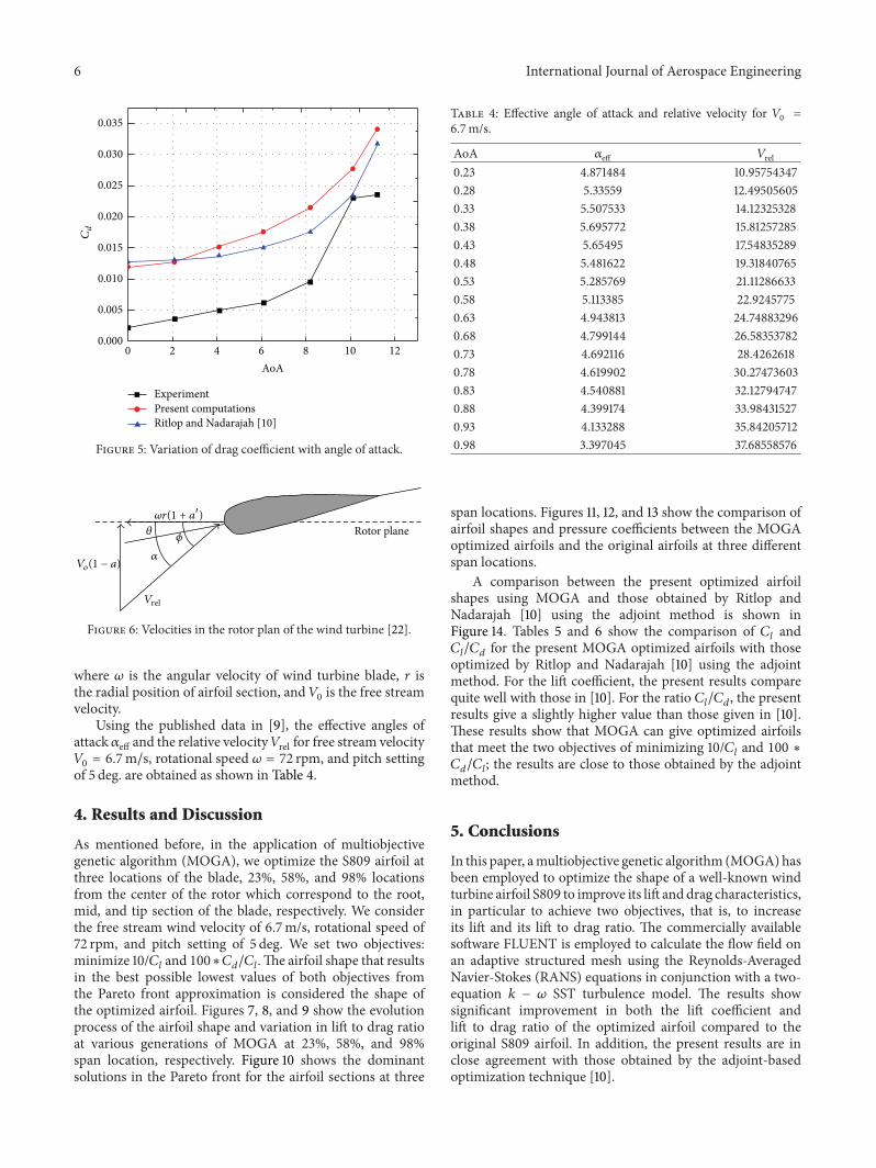

International Journal of
AerospaceEngineeringHindawi Publishing Corporationhttpwwwhindawicom Volume 2014
RoboticsJournal of
Hindawi Publishing Corporationhttpwwwhindawicom Volume 2014
Hindawi Publishing Corporationhttpwwwhindawicom Volume 2014
Active and Passive Electronic Components
Control Scienceand Engineering
Journal of
Hindawi Publishing Corporationhttpwwwhindawicom Volume 2014
International Journal of
RotatingMachinery
Hindawi Publishing Corporationhttpwwwhindawicom Volume 2014
Hindawi Publishing Corporation httpwwwhindawicom
Journal ofEngineeringVolume 2014
Submit your manuscripts athttpwwwhindawicom
VLSI Design
Hindawi Publishing Corporationhttpwwwhindawicom Volume 2014
Hindawi Publishing Corporationhttpwwwhindawicom Volume 2014
Shock and Vibration
Hindawi Publishing Corporationhttpwwwhindawicom Volume 2014
Civil EngineeringAdvances in
Acoustics and VibrationAdvances in
Hindawi Publishing Corporationhttpwwwhindawicom Volume 2014
Hindawi Publishing Corporationhttpwwwhindawicom Volume 2014
Electrical and Computer Engineering
Journal of
Advances inOptoElectronics
Hindawi Publishing Corporation httpwwwhindawicom
Volume 2014
The Scientific World JournalHindawi Publishing Corporation httpwwwhindawicom Volume 2014
SensorsJournal of
Hindawi Publishing Corporationhttpwwwhindawicom Volume 2014
Modelling amp Simulation in EngineeringHindawi Publishing Corporation httpwwwhindawicom Volume 2014
Hindawi Publishing Corporationhttpwwwhindawicom Volume 2014
Chemical EngineeringInternational Journal of Antennas and
Propagation
International Journal of
Hindawi Publishing Corporationhttpwwwhindawicom Volume 2014
Hindawi Publishing Corporationhttpwwwhindawicom Volume 2014
Navigation and Observation
International Journal of
Hindawi Publishing Corporationhttpwwwhindawicom Volume 2014
DistributedSensor Networks
International Journal of