
Research Article Sensitivity Analysis of the TRIGA IPR-R1 ...
10
Research Article Sensitivity Analysis of the TRIGA IPR-R1 Reactor Models Using the MCNP Code C. A. M. Silva, 1 J. A. D. Salomé, 1 B. T. Guerra, 1 C. Pereira, 1 A. L. Costa, 1 M. A. F. Veloso, 1 M. A. B. C. Menezes, 2 and H. M. Dalle 2 1 Departamento de Engenharia Nuclear, Escola de Engenharia, Universidade Federal de Minas Gerais, Campus Pampulha, Avenida Presidente Antˆ onio Carlos 6627, 31270-901 Belo Horizonte, MG, Brazil 2 Centro de Desenvolvimento da Tecnologia Nuclear, Comiss˜ ao Nacional de Energia Nuclear, Campus Pampulha, Avenida Presidente Antˆ onio Carlos 6627, P.O. Box 941, 31270-901, Belo Horizonte, MG, Brazil Correspondence should be addressed to C. Pereira; [email protected] Received 11 April 2014; Accepted 23 July 2014; Published 9 September 2014 Academic Editor: Arkady Serikov Copyright © 2014 C. A. M. Silva et al. is is an open access article distributed under the Creative Commons Attribution License, which permits unrestricted use, distribution, and reproduction in any medium, provided the original work is properly cited. In the process of verification and validation of code modelling, the sensitivity analysis including systematic variations in code input variables must be used to help identifying the relevant parameters necessary for a determined type of analysis. e aim of this work is to identify how much the code results are affected by two different types of the TRIGA IPR-R1 reactor modelling processes performed using the MCNP (Monte Carlo N-Particle Transport) code. e sensitivity analyses included small differences of the core and the rods dimensions and different levels of model detailing. Four models were simulated and neutronic parameters such as effective multiplication factor ( eff ), reactivity (), and thermal and total neutron flux in central thimble in some different conditions of the reactor operation were analysed. e simulated models presented good agreement between them, as well as in comparison with available experimental data. In this way, the sensitivity analyses demonstrated that simulations of the TRIGA IPR-R1 reactor can be performed using any one of the four investigated MCNP models to obtain the referenced neutronic parameters. 1. Introduction e TRIGA IPR-R1 research reactor, located at the Centro de Desenvolvimento da Tecnologia Nuclear (CDTN) spon- sored by Comiss˜ ao Nacional de Energia Nuclear (CNEN) in Belo Horizonte, Brazil, operates since 1960 and it has been an important source of experimental data used in the processes of verification and qualification of several modelling processes of neutronic and thermal-hydraulic codes. Furthermore, the Laboratory for Neutron Activation Analysis of CDTN has been responsible for 70% of the analytical demand using the 0 method of neutron activation analysis, established since 1995. Tests confirmed that the TRIGA IPR-RI reactor presented suitable characteristics to apply the method, mainly due to its stable and homogenous neutron fluxes. At that time, due to the symmetry of the core configuration and the rotary rack, no variations in neutron flux distribution in different channels were taken into account. e average thermal and epithermal fluxes were determined in the reactor rotating carousel facility (CF) [1, 2]. However, the reactor core configuration was changed in 2001 to enable a future power increase from 100 to 250 kW. is change consisted of four fuel rods added to the core, replacing the graphite dummy elements in the circular TRIGA core configuration [3]. In this configuration, the axial and radial neutron fluxes have not been measured and there are no experimental data about these parameters. Previous studies evaluated the neutron flux in eleven irradiation channels of TRIGA comparing the estimated values by MCNP with experimental data [4–6]. e results presented good agreement when compared with experimen- tal data. Another previous work [7] investigated two modelling processes using MCNP code for the TRIGA IPR-R1 reactor. It presented some differences in the core elements dimensions according to technical documents used to perform such models. Moreover, one of them presented more geometrical detailing in relation to the other. Both models presented good Hindawi Publishing Corporation International Journal of Nuclear Energy Volume 2014, Article ID 793934, 9 pages http://dx.doi.org/10.1155/2014/793934
Transcript of Research Article Sensitivity Analysis of the TRIGA IPR-R1 ...
Research ArticleSensitivity Analysis of the TRIGA IPR-R1 Reactor ModelsUsing the MCNP Code
C. A. M. Silva,1 J. A. D. Salomé,1 B. T. Guerra,1 C. Pereira,1 A. L. Costa,1
M. A. F. Veloso,1 M. A. B. C. Menezes,2 and H. M. Dalle2
1 Departamento de Engenharia Nuclear, Escola de Engenharia, Universidade Federal de Minas Gerais,Campus Pampulha, Avenida Presidente Antonio Carlos 6627, 31270-901 Belo Horizonte, MG, Brazil
2 Centro de Desenvolvimento da Tecnologia Nuclear, Comissao Nacional de Energia Nuclear, Campus Pampulha,Avenida Presidente Antonio Carlos 6627, P.O. Box 941, 31270-901, Belo Horizonte, MG, Brazil
Correspondence should be addressed to C. Pereira; [email protected]
Received 11 April 2014; Accepted 23 July 2014; Published 9 September 2014
Academic Editor: Arkady Serikov
Copyright © 2014 C. A. M. Silva et al. This is an open access article distributed under the Creative Commons Attribution License,which permits unrestricted use, distribution, and reproduction in any medium, provided the original work is properly cited.
In the process of verification and validation of code modelling, the sensitivity analysis including systematic variations in code inputvariables must be used to help identifying the relevant parameters necessary for a determined type of analysis. The aim of thiswork is to identify how much the code results are affected by two different types of the TRIGA IPR-R1 reactor modelling processesperformed using the MCNP (Monte Carlo N-Particle Transport) code. The sensitivity analyses included small differences of thecore and the rods dimensions and different levels of model detailing. Fourmodels were simulated and neutronic parameters such aseffectivemultiplication factor (𝑘eff), reactivity (𝜌), and thermal and total neutron flux in central thimble in some different conditionsof the reactor operation were analysed. The simulated models presented good agreement between them, as well as in comparisonwith available experimental data. In this way, the sensitivity analyses demonstrated that simulations of the TRIGA IPR-R1 reactorcan be performed using any one of the four investigated MCNP models to obtain the referenced neutronic parameters.
1. Introduction
The TRIGA IPR-R1 research reactor, located at the Centrode Desenvolvimento da Tecnologia Nuclear (CDTN) spon-sored by Comissao Nacional de Energia Nuclear (CNEN)in Belo Horizonte, Brazil, operates since 1960 and it hasbeen an important source of experimental data used inthe processes of verification and qualification of severalmodelling processes of neutronic and thermal-hydrauliccodes. Furthermore, the Laboratory for Neutron ActivationAnalysis of CDTN has been responsible for 70% of theanalytical demand using the 𝑘
0method of neutron activation
analysis, established since 1995. Tests confirmed that theTRIGA IPR-RI reactor presented suitable characteristics toapply the method, mainly due to its stable and homogenousneutron fluxes. At that time, due to the symmetry of thecore configuration and the rotary rack, no variations inneutron flux distribution in different channels were takeninto account.The average thermal and epithermal fluxes were
determined in the reactor rotating carousel facility (CF) [1, 2].However, the reactor core configuration was changed in 2001to enable a future power increase from 100 to 250 kW. Thischange consisted of four fuel rods added to the core, replacingthe graphite dummy elements in the circular TRIGA coreconfiguration [3]. In this configuration, the axial and radialneutron fluxes have not been measured and there are noexperimental data about these parameters.
Previous studies evaluated the neutron flux in elevenirradiation channels of TRIGA comparing the estimatedvalues by MCNP with experimental data [4–6]. The resultspresented good agreement when compared with experimen-tal data.
Another previous work [7] investigated two modellingprocesses usingMCNP code for the TRIGA IPR-R1 reactor. Itpresented some differences in the core elements dimensionsaccording to technical documents used to perform suchmodels. Moreover, one of them presented more geometricaldetailing in relation to the other. Bothmodels presented good
Hindawi Publishing CorporationInternational Journal of Nuclear EnergyVolume 2014, Article ID 793934, 9 pageshttp://dx.doi.org/10.1155/2014/793934
2 International Journal of Nuclear Energy
agreement with respect to the experimental data and theywere verified in relation to the criticality calculation andreactivity changes.
During the modelling processes, there is not a fixed ruleto perform it and then a large responsibility is passed to thecode user in order to develop an adequate model schemeand each code user can model the same system, with thesame code, in different ways. Therefore, sensitivity analysisincluding systematic variations in code input variables ormodelling parameters must be used to help identify the rele-vant parameters necessary for a determined type of analysis,that is, to determine how “sensitive” a model is consideringchanges in the parameters values or structure model.
Now, to complete the process of sensitivity analysis, reac-tivity data to different control rod positions were obtainedand compared with experimental available data. Further-more, thermal and total neutron flux in the central thimblewere calculated to be used and compared with experimentaldata in future works.
2. Methodology
2.1. TRIGA IPR-R1 Configurations. Detailed description ofthe TRIGA IPR-R1 reactor characteristics used tomodel suchsystem in the MCNP5 code and the models developed canbe found in [7]. The two models were identified as Model 1andModel 2.Themain difference between them is the degreeof the geometry detailing, Model 2 being geometrically moredetailed than Model 1. The main details added in Model 2 inrelation to Model 1 are as follows.
(i) The active length of fuel element was discretized in 36nodes.
(ii) The superior grid, inferior grid, and pneumatic tubewere configured in this model.
(iii) Control rods guide tube is present.(iv) The rotary rack groove is coated by aluminium layer.(v) The samples of irradiation can be inserted in the
rotary rack or in the central thimble or in thepneumatic tubes.
As described before, the differences between the modelsare in the geometry detailing. These models have the samematerials composition obtained from [8] and they wereconfigured according to the characteristics of TRIGA IPR-R1 [7]. In both models, the core was configured in theMCNP5 using a cylinder that contains water, fuel elements,radial reflectors, central tube, control rods, and neutronsource. Each rod has a coordinate value. In these models, therods were filled according to their individual characteristics.Around the core is the rotary rack with adequate groove toinsert the samples to irradiation. The reactor was configuredinside the pool where water surrounds the core and the rotaryrack.
Beyond the detailing in the geometry for the twoMCNP5models analysed, there is a small divergence with respectto elements dimensions according to [8–10]. Therefore, theaim of this investigation is to identify how much the code
results are affected by the different detailing and elementsdimensions of the models analysing four different cases.
(i) Case 1—Model 1 and Dimension 1.
(ii) Case 2—Model 1 and Dimension 2.
(iii) Case 3—Model 2 and Dimension 1.
(iv) Case 4—Model 2 and Dimension 2.
In the simulations, Dimension 1 has the geometric valuesof previous studies [8, 9] and Dimension 2 presents thegeometric values of the technical report [10]. Table 1 showsthe core elements dimensions of the simulated models andinformation about criticality calculation simulations.
2.2. Evaluated Neutronic Parameters. To the sensitivity anal-yses, the neutronic parameters evaluated were the effectivemultiplication factor (𝑘eff), the reactivity (𝜌), and the thermaland total neutron flux in central thimble as described in detailin the next subsections.
2.2.1. Effective Multiplication Factor (𝑘𝑒𝑓𝑓
) and Reactivity.There are three control rods types in the reactor core:regulating rod, safety rod, and shim rod. Each control rodhas a specific position according to its function [7]. Theregulating rod provides fine reactivity control; the shim rodprovides crude reactivity control; and the safety rod is usedfor reactor shutdown. Thus, the insertion of each control rodtype generates different contributions to the core reactivity.In the simulations, each control rod type was individuallyinserted into the core where the 𝑘eff was estimated for each1.0 cm of control rod insertion. As the active length of controlrods is 38 cm, there are 39 𝑘eff values to shim, safety, andregulating rod. In addition, the reactivity effects on totalcontrol rod insertion were compared with experimental dataobtained from [11]. Therefore, the following core conditionswere evaluated:
(a) all control rods withdrawn;
(b) individual and gradual insertion of shim rod;
(c) individual and gradual insertion of safety rod;
(d) individual and gradual insertion of regulating rod;
Experimental data with all control rods withdrawn canbe obtained because TRIGA is the only nuclear reactor inthis category that offers inherent safety. The safety of thereactor would be guaranteed even if the engineered featureswere bypassed and the control rods were rapidly removed.TRIGA is not ordinary light water reactor because much ofits moderation of neutrons is due to the hydrogen that ismixed inwith the fuel itself.Therefore, as the fuel temperatureincreases when the control rods are suddenly removed, theneutrons inside the hydrogen-containing fuel rod becomefaster than the neutrons outside in the cold water. These fastneutrons inside the fuel cause less fission and escape intothe surrounding water. The end result is that the reactorautomatically reduces the power in a fewmilliseconds [10, 11].
International Journal of Nuclear Energy 3
The MCNP5 estimates 𝑘eff values. The 𝑘eff variation(Δ𝑘eff), reactivity (𝜌), and control rods reactivity worth (Δ𝜌)were calculated using the following equations [7]:
Δ𝑘eff = 𝑘eff2 − 𝑘eff1; (1)
𝜌 =𝑘eff − 1
𝑘eff; (2)
Δ𝜌 = 𝜌2− 𝜌1=1
𝑘eff1−1
𝑘eff2, (3)
where the 𝑘eff1 and the 𝑘eff2 are the effective multiplicationfactors to all control rods withdrawn and inserted into thereactor core, respectively. AsMCNP5 is a stochastic code, thestandard deviation (𝜎ST) estimated by this code is printed inthe output filewith the respective 𝑘eff values.The relative error𝑅 was calculated using the following equation:
𝑅 =𝜎ST𝑘eff. (4)
2.2.2. Neutron Flux into Central Thimble. Central thimblepresents themaximumneutron flux due to its central position[8]. This tube is very important due to its application tosample irradiation. In the simulations, it was representedby a cylindrical cell where the neutron flux inside this cellwas performed using the FMESH card of MCNP5 code.This feature allows the user to tally particles on a meshindependent of the problem geometry [12]. In the models,there are 56 cylindrical meshes with the same diameter ofcentral thimble inside the cylindrical cell to estimate theneutron flux inside each mesh. For neutron flux analysisin the central thimble, the following core conditions werestudied:
(a) all control rods withdrawn;
(b) only the shim rod totally inserted into the core;
(c) only the safety rod totally inserted into the core;
(d) only the regulating rod totally inserted into the core.
The MCNP5 estimates the flux using the source specifiedby the user. This estimation does not match the actualneutron source of the reactor. Thus, it is necessary tonormalize the flux values initially calculated by MCNP5. Inthe simulation, this normalization was performed using thefollowing equation [12]:
𝜙𝑁= 𝜙MCNP × (
𝑃 × ]𝑄 × 𝑘eff) , (5)
where 𝜙𝑁is the normalized flux; 𝜙MCNP is the flux estimated
by MCNP5; 𝑃 is the reactor power level; ] is the averagenumber of fission neutrons; and 𝑄 is the recoverable energyper fission event. The values of ], 𝑄, and 𝑘eff are calculatedby MCNP5 and they can be obtained in the output file ofthe code. The user provides the power level (𝑃). In this work,𝑃 = 250 kW.
3. Results
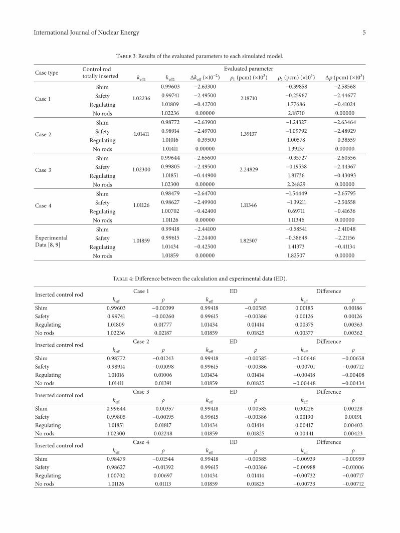
3.1. Reactivity Analysis. Table 2 presents the standard devi-ation (𝜎ST) and relative error (𝑅) to the 𝑘eff calculated byMCNP5 code. In addition, it shows the computation time(CT) for each case. According to [12], the values are reliablewhen the relative error 𝑅 < 0.10. Table 2 shows that therelative error is around 0.011% and, therefore, the calculated𝑘eff values are acceptable. In addition, Table 2 shows thatCases 3 and 4 (configured with Model 2) present CT biggerthan those for Cases 1 and 2 (configured with Model 1).This behaviour is due to Model 2 presenting more detailedgeometry than Model 1. The MCNP code spends more timeto follow particles in detailed geometries due to the increaseof the number of surfaces and volumes. The code tracksparticles through the geometry; it calculates the intersectionof a track’s trajectory with each bounding surface and findsthe minimum positive distance to an intersection. MCNPfinds the correct cell that the particle will enter by checkingthe sense of the intersection point for each surface listed forthe cell. When a complete match is found, MCNP has foundthe correct cell on the other side and the transport continues[12]. Therefore, a large number of surfaces will spend morecomputational time.
Table 3 presents the values of 𝑘eff, 𝜌, Δ𝑘eff, and Δ𝜌 whenthe shim, safety, or regulating rod is totally inserted into core.This table shows these parameters to four studied cases and toexperimental data (ED).The 𝑘eff1 represents the effectivemul-tiplication factor to all control rods withdrawn and 𝑘eff2 is theeffective multiplication factor due to only one of the controlrods (shim, safety, or regulating) inserted into the core.
The investigated cases have the same behaviour when theshim, the safety, or the regulating rod is inserted in the reactorcore (see Table 3). In these cases, the insertion of shim rodinduces the highestΔ𝑘eff, while the insertion of regulating rodcauses the smallest Δ𝑘eff. In this way, the shim rod presentsthe highest Δ𝜌 while the regulating rod presents the lowervalue of Δ𝜌. On the other hand, for the safety and shim rodsthe Δ𝑘eff and Δ𝜌 values are similar. The difference betweenthe behaviours of such rods is due to their positions in thecore.The regulating rod is located in the periphery of the corewhile the safety and shim rods are positioned near to the corecentre.The simulated cases present the same behaviour of theexperimental data.
Table 4 presents the difference between the calculatedvalues (Cases 1, 2, 3, and 4) and the experimental data (ED).Such difference was calculated as
Difference = (CalculatedValue −MeasuredValue) . (6)
Comparing Cases 1 and 2 (Model 1) or Cases 3 and 4(Model 2), Cases 1 and 3 (Dimension 1) present the lowestvalue of the analysed difference. In comparison with theexperimental data, Dimension 1 presents values of 𝑘eff and𝜌 slightly overestimated while Dimension 2 presents valuesslightly underestimated.
As shown in Table 1, the fuel radius of aluminium elementfor Dimension 2 is smaller than for Dimension 1. Moreover,the central zirconium radius of stainless steel element inDimension 2 is higher than in Dimension 1.These differences

4 International Journal of Nuclear Energy
Table 1: Main data of simulated models.
Modified elements description Dimension 1 (cm) Dimension 2 (cm)Active core Outer radius 22.098 22.060
Annular reflectorInner radius 22.730 23.050Outer radius 53.140 53.500
Height 53.950 56.000
Annular reflector claddingInner radius 22.098 22.060Outer radius 54.410 54.500
Height 55.855 58.000
Rotary rack groove Inner radius 29.883 29.050Outer radius 36.957 38.509
Graphite element Graphite radius 1.799 1.789
Aluminium fuel element Fuel radius 1.790 1.780Cladding inner radius 1.799 1.789
Stainless steel fuel element Central zirconium radius 0.286 0.318Cladding outer radius 1.865 1.880
Control rods Cladding inner radius 1.060 0.965Cladding outer radius 1.111 1.110
Information of criticality calculation Dimensions 1 and 2kcode particles number 100,000Simulated cycles number (skipped) 515 (15)Fission source Punctual source at origin of system
Machine processor
System: OpenSUSE 12.1Total memory (RAM): 94.5GBProcessor Intel (R) Xeon (R) CPU X5690 @ 3.47GHZSpeed: 1,596MHzCore number: 24
Table 2: Estimated parameters by MCNP5 code in the simulations.
Case type Evaluated parameter Control rod totally insertedShim Safety Regulating No rods
Case 1
𝑘eff 0.99603 0.99741 1.01809 1.02236𝜎ST 0.00011 0.00011 0.00011 0.00011𝑅 (%) 0.01104 0.01103 0.01080 0.01076
CT (min) 36.14 35.55 35.73 36.20
Case 2
𝑘eff 0.98772 0.98914 1.01016 1.01411𝜎ST 0.00011 0.00011 0.00012 0.00012𝑅 (%) 0.01114 0.01112 0.01188 0.01183
CT (min) 35.07 35.52 35.78 35.81
Case 3
𝑘eff 0.99644 0.99805 1.01851 1.02300𝜎ST 0.00010 0.00011 0.00011 0.00011𝑅 (%) 0.01004 0.01102 0.01080 0.01075
CT (min) 89.84 87.56 88.03 89.06
Case 4
𝑘eff 0.98479 0.98627 1.00702 1.01126𝜎ST 0.00011 0.00011 0.00011 0.00011𝑅 (%) 0.01117 0.01115 0.01092 0.01088
CT (min) 86.94 88.38 88.57 88.43
International Journal of Nuclear Energy 5
Table 3: Results of the evaluated parameters to each simulated model.
Case type Control rodtotally inserted
Evaluated parameter𝑘eff1 𝑘eff2 Δ𝑘eff (×10
−2) 𝜌1(pcm) (×103) 𝜌
2(pcm) (×103) Δ𝜌 (pcm) (×103)
Case 1
Shim
1.02236
0.99603 −2.63300
2.18710
−0.39858 −2.58568Safety 0.99741 −2.49500 −0.25967 −2.44677
Regulating 1.01809 −0.42700 1.77686 −0.41024No rods 1.02236 0.00000 2.18710 0.00000
Case 2
Shim
1.01411
0.98772 −2.63900
1.39137
−1.24327 −2.63464Safety 0.98914 −2.49700 −1.09792 −2.48929
Regulating 1.01016 −0.39500 1.00578 −0.38559No rods 1.01411 0.00000 1.39137 0.00000
Case 3
Shim
1.02300
0.99644 −2.65600
2.24829
−0.35727 −2.60556Safety 0.99805 −2.49500 −0.19538 −2.44367
Regulating 1.01851 −0.44900 1.81736 −0.43093No rods 1.02300 0.00000 2.24829 0.00000
Case 4
Shim
1.01126
0.98479 −2.64700
1.11346
−1.54449 −2.65795Safety 0.98627 −2.49900 −1.39211 −2.50558
Regulating 1.00702 −0.42400 0.69711 −0.41636No rods 1.01126 0.00000 1.11346 0.00000
ExperimentalData [8, 9]
Shim
1.01859
0.99418 −2.44100
1.82507
−0.58541 −2.41048Safety 0.99615 −2.24400 −0.38649 −2.21156
Regulating 1.01434 −0.42500 1.41373 −0.41134No rods 1.01859 0.00000 1.82507 0.00000
Table 4: Difference between the calculation and experimental data (ED).
Inserted control rod Case 1 ED Difference𝑘eff 𝜌 𝑘eff 𝜌 𝑘eff 𝜌
Shim 0.99603 −0.00399 0.99418 −0.00585 0.00185 0.00186Safety 0.99741 −0.00260 0.99615 −0.00386 0.00126 0.00126Regulating 1.01809 0.01777 1.01434 0.01414 0.00375 0.00363No rods 1.02236 0.02187 1.01859 0.01825 0.00377 0.00362
Inserted control rod Case 2 ED Difference𝑘eff 𝜌 𝑘eff 𝜌 𝑘eff 𝜌
Shim 0.98772 −0.01243 0.99418 −0.00585 −0.00646 −0.00658Safety 0.98914 −0.01098 0.99615 −0.00386 −0.00701 −0.00712Regulating 1.01016 0.01006 1.01434 0.01414 −0.00418 −0.00408No rods 1.01411 0.01391 1.01859 0.01825 −0.00448 −0.00434
Inserted control rod Case 3 ED Difference𝑘eff 𝜌 𝑘eff 𝜌 𝑘eff 𝜌
Shim 0.99644 −0.00357 0.99418 −0.00585 0.00226 0.00228Safety 0.99805 −0.00195 0.99615 −0.00386 0.00190 0.00191Regulating 1.01851 0.01817 1.01434 0.01414 0.00417 0.00403No rods 1.02300 0.02248 1.01859 0.01825 0.00441 0.00423
Inserted control rod Case 4 ED Difference𝑘eff 𝜌 𝑘eff 𝜌 𝑘eff 𝜌
Shim 0.98479 −0.01544 0.99418 −0.00585 −0.00939 −0.00959Safety 0.98627 −0.01392 0.99615 −0.00386 −0.00988 −0.01006Regulating 1.00702 0.00697 1.01434 0.01414 −0.00732 −0.00717No rods 1.01126 0.01113 1.01859 0.01825 −0.00733 −0.00712
6 International Journal of Nuclear Energy
−3000
−2500
−2000
−1500
−1000
−500
0
393633302724211815129630
Reac
tivity
wor
th (p
cm)
Shim rod axial positions
Case 1Case 2
Case 3Case 4
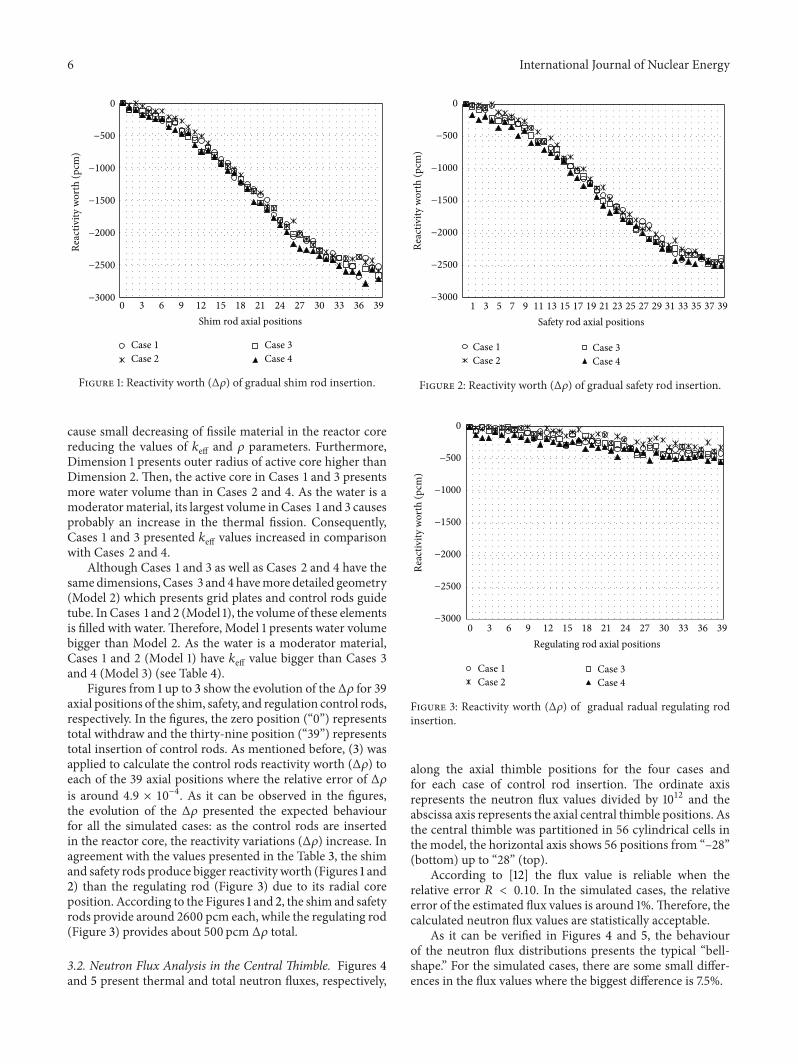
Figure 1: Reactivity worth (Δ𝜌) of gradual shim rod insertion.
cause small decreasing of fissile material in the reactor corereducing the values of 𝑘eff and 𝜌 parameters. Furthermore,Dimension 1 presents outer radius of active core higher thanDimension 2. Then, the active core in Cases 1 and 3 presentsmore water volume than in Cases 2 and 4. As the water is amoderatormaterial, its largest volume in Cases 1 and 3 causesprobably an increase in the thermal fission. Consequently,Cases 1 and 3 presented 𝑘eff values increased in comparisonwith Cases 2 and 4.
Although Cases 1 and 3 as well as Cases 2 and 4 have thesamedimensions, Cases 3 and 4 havemore detailed geometry(Model 2) which presents grid plates and control rods guidetube. In Cases 1 and 2 (Model 1), the volume of these elementsis filled with water.Therefore, Model 1 presents water volumebigger than Model 2. As the water is a moderator material,Cases 1 and 2 (Model 1) have 𝑘eff value bigger than Cases 3and 4 (Model 3) (see Table 4).
Figures from 1 up to 3 show the evolution of the Δ𝜌 for 39axial positions of the shim, safety, and regulation control rods,respectively. In the figures, the zero position (“0”) representstotal withdraw and the thirty-nine position (“39”) representstotal insertion of control rods. As mentioned before, (3) wasapplied to calculate the control rods reactivity worth (Δ𝜌) toeach of the 39 axial positions where the relative error of Δ𝜌is around 4.9 × 10⁻⁴. As it can be observed in the figures,the evolution of the Δ𝜌 presented the expected behaviourfor all the simulated cases: as the control rods are insertedin the reactor core, the reactivity variations (Δ𝜌) increase. Inagreement with the values presented in the Table 3, the shimand safety rods produce bigger reactivity worth (Figures 1 and2) than the regulating rod (Figure 3) due to its radial coreposition. According to the Figures 1 and 2, the shim and safetyrods provide around 2600 pcm each, while the regulating rod(Figure 3) provides about 500 pcm Δ𝜌 total.
3.2. Neutron Flux Analysis in the Central Thimble. Figures 4and 5 present thermal and total neutron fluxes, respectively,
−3000
−2500
−2000
−1500
−1000
−500
0
39373533312927252321191715131197531
Reac
tivity
wor
th (p
cm)
Safety rod axial positions
Case 1Case 2
Case 3Case 4
Figure 2: Reactivity worth (Δ𝜌) of gradual safety rod insertion.
−3000
−2500
−2000
−1500
−1000
−500
0
393633302724211815129630
Reac
tivity
wor
th (p
cm)
Regulating rod axial positions
Case 1Case 2
Case 3Case 4
Figure 3: Reactivity worth (Δ𝜌) of gradual radual regulating rodinsertion.
along the axial thimble positions for the four cases andfor each case of control rod insertion. The ordinate axisrepresents the neutron flux values divided by 1012 and theabscissa axis represents the axial central thimble positions. Asthe central thimble was partitioned in 56 cylindrical cells inthe model, the horizontal axis shows 56 positions from “–28”(bottom) up to “28” (top).
According to [12] the flux value is reliable when therelative error 𝑅 < 0.10. In the simulated cases, the relativeerror of the estimated flux values is around 1%.Therefore, thecalculated neutron flux values are statistically acceptable.
As it can be verified in Figures 4 and 5, the behaviourof the neutron flux distributions presents the typical “bell-shape.” For the simulated cases, there are some small differ-ences in the flux values where the biggest difference is 7.5%.

International Journal of Nuclear Energy 7
2
3
4
5
6
7
8
9
10
11
−28 −23 −18 −13 −8 −3 3 8 13 18 23 28 −28 −23 −18 −13 −8 −3 3 8 13 18 23 28
−28 −23 −18 −13 −8 −3 3 8 13 18 23 28−28 −23 −18 −13 −8 −3 3 8 13 18 23 28
Control rods withdrawn
Case 1Case 2
Case 3Case 4
Case 1Case 2
Case 3Case 4
Case 1Case 2
Case 3Case 4
Case 1Case 2
Case 3Case 4
2
3
4
5
6
7
8
9
10
11Shim rod inserted
2
3
4
5
6
7
8
9
10
11Safety rod inserted
2
3
4
5
6
7
8
9
10
11Regulating rod inserted
Configuration type to thermal neutron flux
Figure 4: Thermal neutron flux (×1012⋅cm−2⋅s−1) versus axial central thimble positions of the simulated models.
As it was analyzed previously, the shim and the safetyrodsmoving cause the biggestΔ𝜌 (see Table 3). Consequently,the insertion of such rods will produce the higher fluxreduction. This behaviour was verified in the simulated cases(see Figures 4 and 5); in spite of the effect of this controlrods insertion, the flux depression is very small. In addition,Table 5 presents the average total flux value in the middle ofcentral thimble where the smallest flux values are of shim andsafety rods inserted.
4. Conclusions
In this work, four cases of the TRIGA IPR-R1 reactor wereanalyzed using the MCNP5 code to estimate values of 𝑘eff, 𝜌,Δ𝑘eff,Δ𝜌 and neutron flux in central thimble in some differentconditions of the reactor operation. The simulated Models2 and 3 present corrections in the geometry dimensions ofsome core elements where Model 3 includes more geometrydetails than Model 2. The aim was to identify how much
Table 5: Average neutron flux in the middle of central thimble.
Inserted controlrod
Thermal neutron flux (×1012⋅cm−2⋅s−1)Case 1 Case 2 Case 3 Case 4
Shim 9.2640 9.7634 9.6070 9.7285Safety 9.5623 9.6109 9.6603 9.6336Regulating 9.7181 10.0224 9.9171 9.9200No rods 9.7271 10.0520 9.9273 9.9469Inserted controlrod
Total neutron flux (×1012⋅cm−2⋅s−1)Case 1 Case 2 Case 3 Case 4
Shim 19.3679 20.0651 20.1728 20.1664Safety 19.8719 19.8786 20.0287 20.2220Regulating 20.0979 20.5195 20.3159 20.7339No rods 20.2836 20.7059 20.3656 20.9112
the code results could be affected according to these differ-ences in the models.

8 International Journal of Nuclear Energy
42
68
10121416182022
42
68
10121416182022
42
68
10121416182022
42
68
10121416182022
−28 −23 −18 −13 −8 −3 3 8 13 18 23 28−28 −23 −18 −13 −8 −3 3 8 13 18 23 28
−28 −23 −18 −13 −8 −3 3 8 13 18 23 28−28 −23 −18 −13 −8 −3 3 8 13 18 23 28
Control rods withdrawn
Case 1Case 2
Case 3Case 4
Case 1Case 2
Case 3Case 4
Case 1Case 2
Case 3Case 4
Case 1Case 2
Case 3Case 4
Shim rod inserted
Safety rod inserted Regulating rod inserted
Configuration type to total neutron flux
Figure 5: Total neutron flux (×1012⋅cm−2⋅s−1) versus axial central thimble positions of the simulated models.
As the results demonstrated, the differences between thesimulated models are small and therefore acceptable. In thisway, the differences in the geometry dimensions detected indifferent reference works generated small variations in theevaluated neutronic parameters and the physical behaviourof these models is the same as all simulated models. Thesimulated models presented good agreement between themfor the evaluated neutronic parameters and also when theyconsidered experimental data.Therefore, the sensitivity anal-yses demonstrated that future works for the TRIGA IPR-R1 simulations can be performed using any of the fourinvestigated models.
Conflict of Interests
The authors declare that there is no conflict of interestsregarding the publication of this paper.
Acknowledgments
The authors are grateful to the Brazilian research fundingagencies, CNEN (Brazil), CNPq (Brazil), CAPES (Brazil), andFAPEMIG (MG/Brazil), for the support.
References
[1] M. A. B. C. Menezes and R. Jacimovic, “Optimised k0-instrumental neutron activation method using the TRIGAMARK I IPR-R1 reactor at CDTN/CNEN, Belo Horizonte,Brazil,” Nuclear Instruments and Methods in Physics ResearchA: Accelerators, Spectrometers, Detectors and Associated Equip-ment, vol. 564, no. 2, pp. 707–715, 2006.
[2] M. A. B. C. Menezes and R. Jacimovic, “Validation of thek0 IAEA software using SMELS material at CDTN/CNEN,Brazil,” Journal of Radioanalytical and Nuclear Chemistry, vol.278, no. 3, pp. 607–611, 2008.

International Journal of Nuclear Energy 9
[3] H. M. Dalle and M. A. Veloso, “Monte Carlo simulation ofTRIGA IPR-R1: reactivity worth, burnup, flux and power,” inProceedings of the 3rd World TRIGA Users Conference, MinasGerais, Brazil, August 2006.
[4] J. A. D. Salome, B. T. Guerra, C. Pereira et al., “Evaluation ofthe thermal neutron flux in samples of Al-Au alloy irradiated inthe carrousel channels of the TRIGA MARK I IPR-R1 reactorusingMCNP code,”Nuclear Engineering and Design, vol. 41, pp.576–583, 2014.
[5] J. A. D. Salome et al., “Evaluation and modelling of the thermalneutron flux in samples in the caroussel channels of the TRIGAMARK I IPR-R1 reactor using Monte Carlo (MCNP),” inProceedings of the EuropeanResearch Reactor Conference (PRFM’12), vol. 1, pp. 423–432, European Nuclear Society, Prague,Czech Republic, 2012.
[6] B. T. Guerra, C. A. M. Silva, C. Pereira et al., “Thermal neutronfluxes characterization in the irradiation channels of the IPR-R1using monte carlo method,” in Proceedings of the Transactionsof European Research Reactor Conference (RRFM ’11), vol. 1, pp.732–736, Bruxelas, European Nuclear Society, Rome, Italy, 2011.
[7] C. A. M. Da Silva, C. Pereira, B. T. Guerra et al., “MCNP5modeling of the IPR-R1TRIGAreactor for criticality calculationand reactivity determination,” Nuclear Engineering and Design,vol. 241, no. 12, pp. 4989–4993, 2011.
[8] H. M. Dalle, Simulacao do Reator IPR-R1Utilizando Metodosde Transporte por Monte Carlo [Doctoral Thesis], Faculdadede Engenharia Quımica, Universidade Estadual de Campinas,Campinas, Brazil, 2005 (Portuguese).
[9] H. M. Dalle, C. Pereira, and R. G. P. Souza, “Neutroniccalculation to theTRIGA Ipr-R1 reactor using theWIMSD4 andCITATION codes,” Annals of Nuclear Energy, vol. 29, no. 8, pp.901–912, 2002.
[10] M. A. Veloso, “Avaliacao Termo-Hidraulica do Reator TRIGAIPR-R1 a 250 kW,” Technical Document NI-EC3-05/05,CDTN/CNEN, Belo Horizonte, Brazil, 2005.
[11] R. M. G. P. Souza et al., “Resultados dos Testes Iniciais parao Aumento de Potencia do Reator TRIGA IPR—R1, NI-IT4-01/01,” Technical Document CDTN/CNEN, Belo Horizonte,2001.
[12] T. E. Booth, F. B. Brown, J. S. Bull et al., “MCNP—a generalmonte carlo n-particle transport code (version 5),” Tech. Rep.LA-UR-03-1987, Los Alamos National Laboratory, 2003.

TribologyAdvances in
Hindawi Publishing Corporationhttp://www.hindawi.com Volume 2014
International Journal of
AerospaceEngineeringHindawi Publishing Corporationhttp://www.hindawi.com Volume 2014
FuelsJournal of
Hindawi Publishing Corporationhttp://www.hindawi.com Volume 2014
Journal ofPetroleum Engineering
Hindawi Publishing Corporationhttp://www.hindawi.com Volume 2014
Industrial EngineeringJournal of
Hindawi Publishing Corporationhttp://www.hindawi.com Volume 2014
Power ElectronicsHindawi Publishing Corporationhttp://www.hindawi.com Volume 2014
Advances in
CombustionJournal of
Hindawi Publishing Corporationhttp://www.hindawi.com Volume 2014
Journal of
Hindawi Publishing Corporationhttp://www.hindawi.com Volume 2014
Renewable Energy
Submit your manuscripts athttp://www.hindawi.com
Hindawi Publishing Corporationhttp://www.hindawi.com Volume 2014
StructuresJournal of
International Journal of
RotatingMachinery
Hindawi Publishing Corporationhttp://www.hindawi.com Volume 2014
EnergyJournal of
Hindawi Publishing Corporationhttp://www.hindawi.com Volume 2014
Hindawi Publishing Corporation http://www.hindawi.com
Journal ofEngineeringVolume 2014
Hindawi Publishing Corporation http://www.hindawi.com Volume 2014
International Journal ofPhotoenergy
Hindawi Publishing Corporationhttp://www.hindawi.com Volume 2014
Nuclear InstallationsScience and Technology of
Hindawi Publishing Corporationhttp://www.hindawi.com Volume 2014
Solar EnergyJournal of
Hindawi Publishing Corporationhttp://www.hindawi.com Volume 2014
Wind EnergyJournal of
Hindawi Publishing Corporationhttp://www.hindawi.com Volume 2014
Nuclear EnergyInternational Journal of
Hindawi Publishing Corporationhttp://www.hindawi.com Volume 2014
High Energy PhysicsAdvances in
The Scientific World JournalHindawi Publishing Corporation http://www.hindawi.com Volume 2014


![IGORR - TRTR 2005 - IPR-R1... · 2005. 10. 18. · Burned Fuel of the TRIGA IPR – R1 Research Reactor Using Monteburns Code [14] Potton D.I. and Trellue H. R., User’s Manual,](https://static.fdocuments.in/doc/165x107/614285f4d9e4dc11f47f1af9/igorr-trtr-ipr-r1-2005-10-18-burned-fuel-of-the-triga-ipr-a-r1-research.jpg)


![Mirror HÔTEL LINE - TRIGA partners80]_catalogue-sheets-m… · Rocker switch Bevelled edge of mirror Integrated Zoom Mirror Special size LEGENDA: STANDARD OPTION >TRIGA brings](https://static.fdocuments.in/doc/165x107/5f6f1d5608609c6c9863d4eb/mirror-htel-line-triga-80catalogue-sheets-m-rocker-switch-bevelled-edge.jpg)

