Research Article Processing and Characterization of...
9
Hindawi Publishing Corporation Journal of Ceramics Volume 2013, Article ID 785210, 8 pages http://dx.doi.org/10.1155/2013/785210 Research Article Processing and Characterization of Yttria-Stabilized Zirconia Foams for High-Temperature Applications Ana María Herrera, Amir Antônio Martins de Oliveira Jr., Antonio Pedro Novaes de Oliveira, and Dachamir Hotza Graduate Program in Materials Science and Engineering (PGMAT), Departments of Chemical (EQA) and Mechanical Engineering (EMC), Federal University of Santa Catarina (UFSC), 88040-900 Florian´ opolis, SC, Brazil Correspondence should be addressed to Dachamir Hotza; [email protected] Received 30 September 2013; Accepted 15 November 2013 Academic Editor: Young-Wook Kim Copyright © 2013 Ana Mar´ ıa Herrera et al. is is an open access article distributed under the Creative Commons Attribution License, which permits unrestricted use, distribution, and reproduction in any medium, provided the original work is properly cited. In this work ceramic foams of 3 and 8 mol% yttria-stabilized zirconia (3YSZ and 8YSZ) were manufactured by the replication method using polystyrene-polyurethane foams with pore sizes in the 7–10 ppi range. A second coating was carried out on presintered foams in order to thicken struts and hinder microstructural defects. e produced ceramic foams were structurally and thermomechanically characterized. Samples recoated with 3YSZ presented the highest relative densities (0.2 ± 0.1) which contributed to a better mechanical and thermal behavior. 1. Introduction Porous radiant burners are devices used in applications benefit from radiant thermal heating. Numerous industries employ this technology for firing and drying, lower pollutant emission, and better product quality reached with these burners [1, 2]. Other functional advantages are a higher flame velocity within the porous structure when compared to a laminar free flame (due to the preheated of reagents), higher turn-down ration, higher efficiency in heat transfer by radiation, and the possibility of burning low calorific value fuels or very lean mixtures [3]. Ceramics foams for porous radiant burners are mainly produced by the replication method from polymeric tem- plates. e method consists in the impregnation of a poly- meric sponge with a ceramic slurry followed by a heat treatment which leads to the burning out of the organic body (sponge) and to the sintering of the ceramic skeleton [4]. Along the manufacture process, there are key parameters that must be taken into account to ensure the final product effectiveness. Among them, the most important are the linear expansion coefficient, maximum working temperature and thermal shock resistance of the ceramic material, thixotropy and pseudoplasticity of the ceramic slurry, and, finally, the heating rate of the thermal treatment. According to the above, the most reliable ceramic materials to work with are cordierite, mullite, silicon carbide, alumina, partially stabi- lized zirconia (YSZ), and some composite systems [5–13]. Cellular ceramics are already commercially available for a wide range of technological applications including filters, membranes, catalytic substrates, thermal insulation, gas burner media, refractory materials, and lightweight struc- tural panels [5–7]. In these cases, reticulated porous ceramics are used because of their functional properties, such as low thermal expansion coefficient and thermal conductivity, high permeability, and chemical inertness [7]. Considering the particularities associated with each specific application, reticulated porous ceramics are prepared and consolidated. Variations of this method employ organic structures, such as wood or cellulose-based materials, as templates for the production of reticulated porous ceramics [3]. e use of a second coating applied to the presintered foams has been reported as a way of enhancing the mechanical resistance due to the thickening of the struts. is procedure hinders microstructural defects that are leſt in the walls of the ceramic foams during the burning out of the organic components [14– 16].
Transcript of Research Article Processing and Characterization of...

Hindawi Publishing CorporationJournal of CeramicsVolume 2013, Article ID 785210, 8 pageshttp://dx.doi.org/10.1155/2013/785210
Research ArticleProcessing and Characterization of Yttria-Stabilized ZirconiaFoams for High-Temperature Applications
Ana María Herrera, Amir Antônio Martins de Oliveira Jr.,Antonio Pedro Novaes de Oliveira, and Dachamir Hotza
Graduate Program in Materials Science and Engineering (PGMAT), Departments of Chemical (EQA) and Mechanical Engineering(EMC), Federal University of Santa Catarina (UFSC), 88040-900 Florianopolis, SC, Brazil
Correspondence should be addressed to Dachamir Hotza; [email protected]
Received 30 September 2013; Accepted 15 November 2013
Academic Editor: Young-Wook Kim
Copyright © 2013 Ana Marıa Herrera et al. This is an open access article distributed under the Creative Commons AttributionLicense, which permits unrestricted use, distribution, and reproduction in any medium, provided the original work is properlycited.
In this work ceramic foams of 3 and 8 mol% yttria-stabilized zirconia (3YSZ and 8YSZ) were manufactured by the replicationmethod using polystyrene-polyurethane foams with pore sizes in the 7–10 ppi range. A second coating was carried out onpresintered foams in order to thicken struts and hinder microstructural defects. The produced ceramic foams were structurallyand thermomechanically characterized. Samples recoated with 3YSZ presented the highest relative densities (0.2 ± 0.1) whichcontributed to a better mechanical and thermal behavior.
1. Introduction
Porous radiant burners are devices used in applicationsbenefit from radiant thermal heating. Numerous industriesemploy this technology for firing and drying, lower pollutantemission, and better product quality reached with theseburners [1, 2].
Other functional advantages are a higher flame velocitywithin the porous structure when compared to a laminar freeflame (due to the preheated of reagents), higher turn-downration, higher efficiency in heat transfer by radiation, and thepossibility of burning low calorific value fuels or very leanmixtures [3].
Ceramics foams for porous radiant burners are mainlyproduced by the replication method from polymeric tem-plates. The method consists in the impregnation of a poly-meric sponge with a ceramic slurry followed by a heattreatment which leads to the burning out of the organic body(sponge) and to the sintering of the ceramic skeleton [4].Along the manufacture process, there are key parametersthat must be taken into account to ensure the final producteffectiveness. Among them, themost important are the linearexpansion coefficient, maximum working temperature andthermal shock resistance of the ceramic material, thixotropy
and pseudoplasticity of the ceramic slurry, and, finally, theheating rate of the thermal treatment. According to theabove, the most reliable ceramic materials to work with arecordierite, mullite, silicon carbide, alumina, partially stabi-lized zirconia (YSZ), and some composite systems [5–13].
Cellular ceramics are already commercially availablefor a wide range of technological applications includingfilters, membranes, catalytic substrates, thermal insulation,gas burnermedia, refractorymaterials, and lightweight struc-tural panels [5–7]. In these cases, reticulated porous ceramicsare used because of their functional properties, such aslow thermal expansion coefficient and thermal conductivity,high permeability, and chemical inertness [7]. Consideringthe particularities associated with each specific application,reticulated porous ceramics are prepared and consolidated.
Variations of thismethod employ organic structures, suchas wood or cellulose-based materials, as templates for theproduction of reticulated porous ceramics [3]. The use of asecond coating applied to the presintered foams has beenreported as a way of enhancing the mechanical resistancedue to the thickening of the struts. This procedure hindersmicrostructural defects that are left in the walls of the ceramicfoams during the burning out of the organic components [14–16].

2 Journal of Ceramics
Zirconia has been mentioned among possible candidatesas material for high-temperature (for continuous operationabove 1600∘C) porous burners [17, 18]. Nevertheless, phasetransformations that are dependent on temperature andcomposition are obstacles to a broader application of thismaterial in radiant burners. Yttria-stabilized zirconia (YSZ)has been developed to hinder allotropic changes among thezirconia phases by replacing zirconium (Zr4+) by yttrium ions(Y3+) into the zirconia matrix [4]. Monoclinic is the moststable phase at room temperature, but YSZ allows tetragonaland cubic phases to be stable at lower temperatures withenhanced mechanical, thermal, and electrical properties.
The aim of this work was to evaluate the functionality,quality, and thermomechanical strength of 3 and 8mol%yttria-stabilized zirconia (3YSZ or 8YSZ), as base materialsfor the porous radiant burners. From the mechanical pointof view, 3YSZ would be the best option, but 8YSZ waschosen due its high oxygen ion conduction while blockingelectronic conduction.This feature makes 8YSZ the standardelectrolyte material for solid oxide fuel cells (SOFC), whichmust be operated at intermediate to high temperatures (600to 1000∘C).Themotivation in this case is to associate a porousburner to a no-chamber SOFC, providing compatibilitybetween both devices [19].
2. Materials and Methods
2.1. Materials. The starting materials were 3YSZ (TZ-3YB-E, Tosoh, Japan), with a mean particle size (d50) of 0.45 𝜇mand density of 6.05 g/cm3, and 8YSZ (YSZ8-U1, NexTech,USA) with a mean particle size (d50) of 0.32 𝜇m anddensity of 7.80 g/cm3. Ammonium polyacrylate (NH4PAA,Darvan, 821-A, Vanderbilt, USA) was used as dispersant andpolyvinyl alcohol (PVA, (CH
2CH(OH)
𝑛), molecular weight:
70–100 g/mol Vetec, Brazil) as binder. To obtain a homoge-neous slurry without bubbles, an antifoamer emulsion basedon silicone was needed, (Sigma-Aldrich, Brazil).
Finally, for the manufacture of the ceramic foams by thereplication method, a polystyrene-polyurethane foam (CrestFoam Industries, USA) with an average pore density of 10 ppiand nominal density of 0.03 g/cm3 was employed.
2.2. Methods. Ceramic powders were characterized by zetapotential (Zetananosizer, Malvern, USA) and X-ray diffrac-tion (X’pert, PW3710, Phillips, the Netherlands), based on0.05∘ step, 1 s of step time, and a reading interval of 2𝜃 from0∘ to 118∘. Rheological studies were performed for both 3YSZand 8YSZ suspensions. The effect of the solids load, variedbetween 75 and 77.5 wt%, and binder amount, varied between3.5 and 4.5 mass% suspension weight (base: 100wt%), wereevaluated. The ceramic foams were manufactured by thereplication method. The impregnation step consisted insoaking the compressed sponge into the ceramic suspensionand then releasing the tension so that the sponge could absorbas much as possible of the slurry. Subsequently, it is taken outto be wrung and remove all the slurry in excess, followed by avery soft air-spray to open the closed cells. Finally, it is driedunder room temperature during 24 h and then presintered
according to the following thermal cycles: 1∘C/min from 25to 200∘C; 0.5∘C/min to 600∘C; then 5∘C/min to 1150∘C witha holding time of 2 h. Subsequently, the samples were cooled(at 10–15∘C/min) down to the room temperature.
A second coating was applied (in some cases) with alighter suspension of the same material (70% solids, 3.5%binder).The sintering step was carried out with a heating rateof 7∘C/min from room temperature to 900∘C and 3∘C/minto 1600∘C, with a holding time of 2 h, and then samples werecooled (at 10∘C/min) down to room temperature.
The sintered YSZ foams were characterized by its relativedensity and total porosity, wherein the geometrical densitywas calculated by measuring the mass and volume of thesamples and the solidmaterial density by helium picnometry.
Scanning electron microscopy (SEM, Phillips XL 30,the Netherlands) was used to access the microstructure offoams. Mechanical properties were measured according tousual procedures (compression strength [20], thermal shockresistance [21]). Finally, the foams were tested as porousradiant burners, at a constant fuel/air mixture ratio of 0.9at different time cycles: 10min−1 cycle, 10min−5 cycles, and360min−1 cycle.
The mechanical testing was performed in 10 cylindricalsamples (diameter equal to height) of sintered YSZ. The loadvelocity was 0.5mm/s, based on the work of Elverum et al.,[20] with the aim to compare results and materials. A uni-versal mechanical testing machine was employed (DL2000,EMIC, Brazil).
The thermal shock test consisted in exposing the ceramicfoams with a prismatic shape (170 × 30 × 25mm) at high/lowtemperatures based on ASTM C1198-96 [22]. The sampleswere placed into a muffle furnace at 1000∘C during 15minand taken out and immediately cooled by forced air (hairdryer) to room temperature. This procedure was repeated4, 8, and 12 times. The loss of the mechanical propertiescaused by the induced thermal shock was verified by mea-suring Young’s modulus. This parameter was measured by anondestructive method, submitting the ceramic foam to animpulse which excites the natural vibration frequencies of thestructure. Young’smodulus is related to the natural frequency,geometric dimensions, and mass of the ceramic foam sampleby
𝐸 = 0.9465 ⋅ (
𝑚 ⋅ 𝑓2
𝑓
𝑏) ⋅ (𝐿2
𝑡2) ⋅ 𝑇1, (1)
where
𝐸 is the Young modulus,
𝑚 is the sample mass,
𝑏, 𝐿, 𝑡 are the width, the length, and the thickness ofthe sample, respectively,
𝑓𝑓is the fundamental frequency, and
𝑇1is the correction factor related to the fundamental
flexional mode.

Journal of Ceramics 3
Sample
Hammer forimpact
Software: LMS-testlab
(data analysis)
Figure 1: Dynamic test for identifying the structure’s Young modulus.
The total damage in the ceramic structure due to thethermal shock may be estimated from
𝐷𝐸= 1 −𝜎𝑐
𝜎0
≈ 1 −
𝐸𝑓
𝐸0
, (2)
where𝐷𝐸is the total damage factor, from 0 to 1,𝐸𝑓is the last calculated Young modulus,𝐹𝑓is the last calculated mechanical strength,𝐸0is the initial Young modulus, and𝜎0is the initial calculated mechanical strength.
The chart in Figure 1 represents the above-describedthermal shock test.
An experimental test with the ceramic foams as porousburners was performed. The test employed disk shapedsamples, with 35mm diameter and 35mm thickness, fittedinside a steel tube using a fiber mat to thermally insulatethe ceramic foams from the tube wall. The burner was fedwith a natural gas and air mixture with fuel equivalenceratio of 0.9. The flame, after approximately 2-3min afterignition, was stabilized within the porous matrix. The outletsurface of the burner was allowed to radiate heat freely tothe external ambient. The burner was submitted to periodsof continuous operation of 10min and 6 h. The adiabaticflame temperature corresponding to this equivalence ratio isapproximately 2150K [23]. This high operation temperaturewas specified with the aim to test the intrinsic properties ofthe YSZ samples.
The double-coated 3YSZ samples worked at the specifiedequivalence rate and with a flame velocity of 15 cm/s, asshown in Figure 2.
3. Results and Discussions
3.1. X-Ray Diffraction. Figure 3 shows the X-ray diffrac-tograms obtained for the zirconium powders. As expected,3YSZ (Figure 3(a)) corresponds mainly to the tetragonalphase, with aminor presence ofmonoclinic phase, whichmaybe seen as little isles in the tetragonal matrix, which mightcontribute to a higher fracture toughness to thematerial [24].For 8YSZ (Figure 3(b)), sharp peaks correspondent to thecubic phase were detected, as expected. This phase is knownto present a characteristic grain growth, which reduces themechanical resistance of the material [25].
SBR: 10 ppi
Insulating
PR: 40 ppi
Thermocouples:R = 35 mm
Tsup
Tc9
Tc8Tc7Tc6Tc5
Tc4Tc3
Tc2Tc1 Tw1
Tw9
Tw8Tw7
Tw6Tw5
Tw4Tw3Tw2
20 m
m
10 m
m
r x
17.5 mm
110 mm
Perforated plate
(Al2O3)
Lq=80
mm
Figure 2: Setup of the porous burner test at a lab scale.
3.2. Rheological Characterization. Theeffect of the dispersanton the isoelectric point (IEP) of the materials was evaluated.In Figure 4 it is shown how the pH at the IEP is shiftedfrom the basic to the acid range. The 3YSZ suspension hasits original IEP at pH 6.9, the value that converges with theones found in the literature, [26, 27], this IEP was fell inthe range of 5.2 to 7.2. Adding one drop of dispersant to thesolution, the IEP was then located at a pH 2.9. The samefeature might be observed for the 8YSZ suspension. IEP isoriginally at pH 7.5, the value which converges with the IPE’sof 8YSZ powder (Sigma-Aldrich) at 9.2 and the 8YSZ powder(Innovano) at 7.2. Adding a dispersant drop, the IEP movesto 3.2. This phenomenon is attributed to the change of theelectrochemical properties of the particles surface when thedispersant particles are attached to them [26, 27].
Four formulations were analyzed for each material, aspreviously described.The guide parameters were the pseudo-plasticity and thixotropy, rheological properties that shouldbe present in any suspension to be applied in the replicamethod. A high viscosity is desired at low shear stress and alow viscosity when at high shear stress. This ensures, respec-tively, that the slurry will flow into the reticulated structure bythe impregnation, and,when at rest, the slurrywill be stronglyadhered to the polymeric walls. A high thixotropy (large areabetween the flow curves) corresponds to the facility that theslurry will recover its initial viscosity after the impregnationprocess [28, 29]. Figure 5 shows the thixotropy graphs ofboth systems, where those two properties can be observed.Figure 5(a) corresponds to the 3YSZ suspensions with 77.5%

4 Journal of Ceramics
0 10 20 30 40 50 60 70 800
200
400
600
800
1000
1200
1400
1600
M
M
MT
T
T
T
T
TM
M
Inte
nsity
M
T
M Monoclinical phaseT Tetragonal phase
Position (2𝜃)
(a)
0 10 20 30 40 50 60 70 800
1000
2000
3000
4000
5000
6000
C
C
C
C
CInte
nsity
C
C Cubic phase
Position (2𝜃)
(b)
Figure 3: X-ray diffraction of the YSZ powders after sintering: (a) 3YSZ; (b) 8YSZ.
1 2 3 4 5 6 7 8 9 10 11
−70
−60
−50
−40
−30
−20
−10
0
10
Zeta
pot
entia
l (m
V)
pH
3YSZ with disp 3YSZ w/out disp
IPE = 2.9 IPE = 6.9
(a)
1 2 3 4 5 6 7 8 9 10 11
−60
−40
−20
0
20
40
Zeta
pot
entia
l (m
V)
pH
8YSZ w/out disp8YSZ with disp
IPE=3.25 IPE=7.48
(b)
Figure 4: Zeta potential of zirconia suspensions as a function of pH and added dispersant. (a) 3YSZ; (b) 8YSZ.
solids and 3.5% binder. In the case of 8YSZ (Figure 5(b)), theformulation with 77.5% solids and 4.5% binder was selected.Themaximum amount of solids is naturally desired [3, 14, 27,30].
In Figure 5 the thixotropy curves present different behav-iors. The steeper the curve, the higher the viscosity at highshear stress and consequently the higher the initial viscosity[15]. Those characteristics provide a thicker layer whencoating and, consequently, higher homogeneity and betterdensification of the material [14].
3.3. Physical Characterization of Foams. Relative density andporosity were determined for the three classes of yttria-stabilized zirconia foams produced, Table 1.
Higher relative density values were obtained for doublecoated 3YSZ in comparison to single-coated 3YSZ and 8YSZ.
This result is a consequence of the slightly larger amount ofsolids in the cellular structure, which also affects the porosityof the ceramic foam.
Images obtained by SEM allow for having an overallview of the foam structures obtained. Figure 6 presents thedifferent types of foams manufactured. Figures 6(a) and 6(b)correspond to single-coated 3YSZ and 8YSZ, respectively.Homogeneous surfaces with few microstructural defects areobserved, as micropores inside the struts and minicracks.Figure 6(c) corresponds to a double-coated 3YSZ foam show-ing how the internal surfaces have more micropores andmicrocracks than the external walls. Moreover, the verticesare rounded after the recoating, which might enhance themechanical strength of the structure [14]. Figure 6(d) showstypical defects, characteristic of the replica method. Never-theless, the thicker walls obtained with a recoating are seen,as well.

Journal of Ceramics 5
0 100 200 300 400 5000
50
100
150
200
250
300
75solids - 3.5binder75solids - 4.5binder
77.5solids- 4.5binder77.5solids - 3.5binder
Shear rate (s−1)
Shea
r stre
ss (P
a)
(a)
0 100 200 300 400 5000
100
200
300
400
500
Shea
r stre
ss (P
a)
75solids - 3, 5binder75solids - 4, 5binder
77,5solids- 3, 5binder77,5solids - 4, 5binder
Shear rate (s−1)
(b)
Figure 5: Rheogram of the ceramic slurries: (a) 3YSZ; (b) 8YSZ, for different solid and binder concentrations.
(a) (b)
(c) (d)
Figure 6: SEM images of YSZ foams: (a) single-coated 3YSZ; (b) single-coated 8YSZ; (c) double-coated 3YSZ; (d) conventional defect left bythe organic compounds burning out in a double-coated 3YSZ foam.

6 Journal of Ceramics
Table 1: Relative density and total porosity values of zirconia foams.
YSZ foams 𝜌geometric (g/cm3) 𝜌solid-mat. (g/cm
3) Relative density, 𝜌𝑟
Porosity (%)3YSZ, double coated 1.1 ± 0.1 5.7 0.20 ± 0.10 80.1 ± 0.1
3YSZ, single coated 0.5 ± 0.3 5.7 0.10 ± 0.30 90.0 ± 0.3
8YSZ 0.4 ± 0.3 5.8 0.08 ± 0.30 92.0 ± 0.3
0 5 10 15 20 25 300
1
2
3
4
5
6
7
Nontested sample: max. mech. strgth: 3.376 MPa Tested sample as PB: max. mech. strgth: 0.087 MPa
Mec
hani
cal s
tren
gth
(MPa
)
Plate displacement (mm)
Figure 7: Compression strength of samples before/after the porousburner test.
0 4 8 120
20
40
60
80
(A2) 3YSZ-single coat, 20%
(A1) 3YSZ-single coat, 28.8%
(A2) 3YSZ-double coat, 56.2%
De (
%)
Cycle
8YSZ- 81%
(A1) 3YSZ-double coat, 70%
Figure 8: Damage done to the YSZ foams owed to a thermal shocktest.
3.4. Mechanical Characterization of Foams. The mechanicalstrength of the double-coated 3YSZ samples (2.3 ± 0.7MPa)is higher than that of the single-coated 3YSZ (0.8 ± 0.3MPa)or 8YSZ samples (0.30 ± 0.04MPa). This fact is owed to thelower density of microstructural defects and thicker wallsfor the 3YSZ double-coated samples.The average mechanicalstrength of samples was 2.3 ± 0.7MPa which is comparableto the values found by Elverum et al. [20], in which averagemechanical strength was of 1.8MPa.
The compression strength test was also applied to sampleswhich could overcome the burning test. Figure 7 presents
Table 2: Values of Young modulus for single/double YSZ samplesafter thermal shock test.
𝑓𝑓
(Hz) E (GPa)8YSZ
A1W/out cycles 597 0.104 cycles 330 0.038 cycles 259 0.02
3YSZ double coatedA1
W/out cycles 2373 5.074 cycles 1673 2.528 cycles 1430 1.8412 cycles 1296 1.51
A2W/out cycles 1721 2.254 cycles 1390 1.478 cycles 1202 1.112 cycles 1139 0.98
3YSZ single coatedA1
W/out cycles 1257 0.424 cycles 1108 0.338 cycles 1084 0.3212 cycles 1060 0.30
A2W/out cycles 1021 0.234 cycles 958 0.208 cycles 919 0.1812 cycles 911 0.18
the results obtained of a sample of double-coated 3YSZ thatwas tested as a porous burner in comparison to the bestresult obtained for a sample of the same group in Table 2. Ascan be seen, the mechanical properties of the tested samplewere deeply reduced, with amaximum strength of 0.087MPa,corresponding to 2.6% of the 3.37MPa of the nontestedsample.
Table 2 presents the fundamental frequencies and thecorresponding Young moduli of the samples subjected up to12 thermal shock cycles. As it can be seen, after 12 cycles,the highest Young modulus belonged to the double-coated3YSZ samples. The 8YSZ samples could withstand just up to8 cycles.
The total damage done to the structure due to the thermalshock test (DE, Figure 8) is lower for the single-coated 3YSZsample (between 20–28%), while the double-coated 3YSZ
Journal of Ceramics 7
(a) (b) (c)
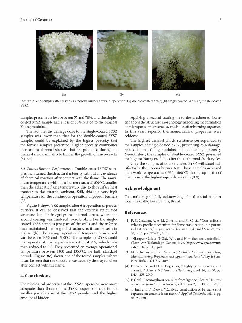
Figure 9: YSZ samples after tested as a porous burner after 6 h operation: (a) double-coated 3YSZ; (b) single-coated 3YSZ; (c) single-coated8YSZ.
samples presented a loss between 55 and 70%, and the single-coated 8YSZ sample had a loss of 80% related to the originalYoung modulus.
The fact that the damage done to the single-coated 3YSZsamples was lower than that for the double-coated 3YSZsamples could be explained by the higher porosity thatthe former samples presented. Higher porosity contributesto relax the thermal stresses that are produced during thethermal shock and also to hinder the growth of microcracks[31, 32].
3.5. Porous Burners Performance. Double-coated 3YSZ sam-ples maintained the structural integrity without any evidenceof chemical reaction after contact with the flame. The maxi-mum temperature within the burner reached 1600∘C, smallerthan the adiabatic flame temperature due to the surface heattransfer to the external ambient. Still, this is a very hightemperature for the continuous operation of porous burners[33].
Figure 9 shows YSZ samples after 6 h operation as porousburners. It can be observed that the external reticulatedstructure kept its integrity; the internal struts, where thesecond coating was hindered, were broken. For the single-coated 3YSZ samples just part of the walls and the inferiorbase maintained the original structure, as it can be seen inFigure 9(b). The average operational temperature achievedwas between 1450 and 1500∘C. The samples of 8YSZ couldnot operate at the equivalence ratio of 0.9, which wasthen reduced to 0.8. They presented an average operationaltemperature between 1300 and 1350∘C, for both standardperiods. Figure 9(c) shows one of the tested samples, whereit can be seen that the structure was severely destroyed whenafter contact with the flame.
4. Conclusions
The rheological properties of the 8YSZ suspension weremoreadequate than those of the 3YSZ suspension, due to thesmaller particle size of the 8YSZ powder and the higheramount of binder.
Applying a second coating on to the presintered foamsenhanced the structuremorphology, hindering the formationofmicropores,microcracks, and holes after burning organics.In this case, superior thermomechanical properties wereachieved.
The highest thermal shock resistance corresponded tothe samples of single-coated 3YSZ, presenting 25% damage,related to the Young modulus, due to the high porosity.Nevertheless, the samples of double-coated 3YSZ presentedthe highest Young modulus after the 12 thermal shock cycles.
Only the samples of double-coated 3YSZ withstood sat-isfactorily the porous burner test. Those samples achievedhigh work temperatures (1550–1600∘C) during up to 6 h ofoperation at the highest equivalence ratio (0.9).
Acknowledgment
The authors gratefully acknowledge the financial supportfrom the CNPq Foundation, Brazil.
References
[1] R. C. Catapan, A. A. M. Oliveira, and M. Costa, “Non-uniformvelocity profile mechanism for flame stabilization in a porousradiant burner,” Experimental Thermal and Fluid Science, vol.35, no. 1, pp. 172–179, 2011.
[2] “Nitrogen Oxides (NOx), Why and How they are controlled,”Clean Air Technology Center, 1999, http://www.epa.gov/ttn/catc/dir1/fnoxdoc.pdf.
[3] M. Scheffler and P. Colombo, Cellular Ceramics: Structure,Manufacturing, Properties and Applications, JohnWiley & Sons,New York, NY, USA, 2005.
[4] P. Colombo and H. P. Degischer, “Highly porous metals andceramics,”Materials Science and Technology, vol. 26, no. 10, pp.1145–1158, 2010.
[5] P. Greil, “Biomorphous ceramics from lignocellulosics,” Journalof the European Ceramic Society, vol. 21, no. 2, pp. 105–118, 2001.
[6] T. Inui and T. Otowa, “Catalytic combustion of benzene-sootcaptured on ceramic foammatrix,”Applied Catalysis, vol. 14, pp.83–93, 1985.
8 Journal of Ceramics
[7] T. Mizrah, A. Maurer, L. Gauckler, and J. P. Gabathuler, SAEPaper 890172, 1989.
[8] L. Montanaro, Y. Jorand, G. Fantozzi, and A. Negro, “Ceramicfoams by powder processing,” Journal of the European CeramicSociety, vol. 18, no. 9, pp. 1339–1350, 1998.
[9] P. Colombo and E. Bernardo, “Macro- and micro-cellularporous ceramics from preceramic polymers,” Composites Sci-ence and Technology, vol. 63, no. 16, pp. 2353–2359, 2003.
[10] M. F. Ashby, “The mechanical properties of cellular solids,”Metallurgical Transactions A, vol. 14, no. 9, pp. 1755–1769, 1983.
[11] R. Brezny and J. D. Green, “Structure and properties of ceram-ics,”Materials Science and Technology, vol. 11, pp. 467–516, 1992.
[12] F. Lange and T. K. Miller, “Open cell low density ceramics fabri-cated from reticulated polymer substrates,” Advanced CeramicsMaterials, vol. 2, no. 4, pp. 827–831, 1987.
[13] K. Lannguth, “Particle size range as a factor influencing com-pressibility of ceramic powder,” Ceramics International, vol. 21,pp. 237–242, 1995.
[14] V. S. Stunican, R. C.Hink, and S. P. Ray, “Phase equilibriums andordering in the system zirconia-yttria,” Journal of the AmericanCeramic Society, vol. 61, pp. 17–21, 1988.
[15] X. W. Zhu, D. L. Jiang, S. H. Tan, and Z. Q. Zhang, “Improve-ment in the strut thickness of reticulated porous ceramics,”Journal of the American Ceramic Society, vol. 84, no. 7, pp. 1654–1656, 2001.
[16] X. Yao, S. Tan, Z.Huang, andD. Jiang, “Effect of recoating slurryviscosity on the properties of reticulated porous silicon carbideceramics,” Ceramics International, vol. 32, no. 2, pp. 137–142,2006.
[17] S. Y. Gomez, O. Alvarez, J. Escobar, J. B. Rodriguez, C. Rambo,andD.Hotza, “Relationship between rheological behaviour andfinal structure of Al
2
O3
and YSZ foams produced by replica,”Advances inMaterials Science and Engineering, vol. 2012, ArticleID 549508, 9 pages, 2012.
[18] R. Stevens, Zirconia and Zirconia Ceramics, Magnesium Elek-tron Publication, 2nd edition, 1986.
[19] J. Aguilar and D. Hotza, “Configuraciones alternativas para cel-das de combustible de oxido solido,” Revista Latinoamericanade Metalurgia y Materiales, vol. 33, pp. 172–185, 2013.
[20] P. J. Elverum, J. L. Ellzey, and D. Kovar, “Durability of YZAceramic foams in a porous burner,” Journal of Materials Science,vol. 40, no. 1, pp. 155–164, 2005.
[21] L. C. Cossolino and A. Pereira, “Modulos elasticos: visao gerale metodos de caraterizacao,” ATCP Engenharia Fısica, 2010.
[22] ASTM C1198-96, “Standard test method for dynamic young’smodulus, shear modulus and poisson’s ratio for advancedceramics,” American Society for Testing Materials, 1996.
[23] F. M. Pereira, A. A. M. Oliveira, and F. F. Fachini, “Asymptoticanalysis of stationary adiabatic premixed flames in porous inertmedia,”Combustion and Flame, vol. 156, no. 1, pp. 152–165, 2009.
[24] J. Sun, L. Gao, and J. Guo, “Influence of the Initial pH on theadsorption behaviour of dispersant on nano zirconia powder,”Journal of the European Ceramic Society, vol. 19, no. 9, pp. 1725–1730, 1999.
[25] J. Wang and L. Gao, “Surface and electrokinetic propertiesof Y-TZP suspensions stabilized by polyelectrolytes,” CeramicsInternational, vol. 26, no. 2, pp. 187–191, 2000.
[26] J. Luo and R. Stevens, “Tetragonality of nanosized 3Y-TZPpowders,” Journal of the American Ceramic Society, vol. 82, no.7, pp. 1922–1924, 1999.
[27] M. Filal, C. Petot,M.Mokchah, C. Chateau, and J. L. Carpentier,“Ionic conductivity of yttrium-doped zirconia and the ‘compos-ite effect’,” Solid State Ionics, vol. 80, no. 1-2, pp. 27–35, 1995.
[28] B. R. Moreno, “Reologıa de suspensiones ceramicas,” ConsejoSuperior de Investigaciones Cientıficas, vol. 17, p. 325, 2005.
[29] A. M. Herrera, O. Alvarez, J. Escobar, V. Moreno, and D.Hotza, “Fabrication and characterization of alumina foams forapplication in radiant porous burners,” Revista Materia, vol. 17,pp. 973–987, 2012.
[30] D. Hotza, “Colagem de folhas ceramicas,” Ceramica, vol. 43, pp.157–164, 1994.
[31] V. R. Vedula, D. J. Green, and J. R. Hellmann, “Thermal fatigueresistance of open cell ceramic foams,” Journal of the EuropeanCeramic Society, vol. 18, no. 14, pp. 2073–2081, 1998.
[32] L. Shen, M. Liu, X. Liu, and B. Li, “Thermal shock resistanceof the porous Al
2
O3
/ZrO2
ceramics prepared by gelcasting,”Materials Research Bulletin, vol. 42, no. 12, pp. 2048–2056, 2007.
[33] J. R. Howell, M. J. Hall, and J. L. Ellzey, “Combustion ofhydrocarbon fuels within porous inert media,” Progress inEnergy and Combustion Science, vol. 22, no. 2, pp. 121–145, 1996.

Submit your manuscripts athttp://www.hindawi.com
ScientificaHindawi Publishing Corporationhttp://www.hindawi.com Volume 2014
CorrosionInternational Journal of
Hindawi Publishing Corporationhttp://www.hindawi.com Volume 2014
Polymer ScienceInternational Journal of
Hindawi Publishing Corporationhttp://www.hindawi.com Volume 2014
Hindawi Publishing Corporationhttp://www.hindawi.com Volume 2014
CeramicsJournal of
Hindawi Publishing Corporationhttp://www.hindawi.com Volume 2014
CompositesJournal of
NanoparticlesJournal of
Hindawi Publishing Corporationhttp://www.hindawi.com Volume 2014
Hindawi Publishing Corporationhttp://www.hindawi.com Volume 2014
International Journal of
Biomaterials
Hindawi Publishing Corporationhttp://www.hindawi.com Volume 2014
NanoscienceJournal of
TextilesHindawi Publishing Corporation http://www.hindawi.com Volume 2014
Journal of
NanotechnologyHindawi Publishing Corporationhttp://www.hindawi.com Volume 2014
Journal of
CrystallographyJournal of
Hindawi Publishing Corporationhttp://www.hindawi.com Volume 2014
The Scientific World JournalHindawi Publishing Corporation http://www.hindawi.com Volume 2014
Hindawi Publishing Corporationhttp://www.hindawi.com Volume 2014
CoatingsJournal of
Advances in
Materials Science and EngineeringHindawi Publishing Corporationhttp://www.hindawi.com Volume 2014
Smart Materials Research
Hindawi Publishing Corporationhttp://www.hindawi.com Volume 2014
Hindawi Publishing Corporationhttp://www.hindawi.com Volume 2014
MetallurgyJournal of
Hindawi Publishing Corporationhttp://www.hindawi.com Volume 2014
BioMed Research International
MaterialsJournal of
Hindawi Publishing Corporationhttp://www.hindawi.com Volume 2014
Nano
materials
Hindawi Publishing Corporationhttp://www.hindawi.com Volume 2014
Journal ofNanomaterials