Research Article Optimized Wideband Impedance Matching ...
14
Research Article Optimized Wideband Impedance Matching Balun for Conducting Two-Arm Antennas Khalid F. A. Hussein Microwave Engineering Department, Electronics Research Institute, Cairo 12622, Egypt Correspondence should be addressed to Khalid F. A. Hussein; khalid [email protected] Received 3 May 2014; Revised 20 August 2014; Accepted 11 September 2014; Published 14 October 2014 Academic Editor: Sembiam R. Rengarajan Copyright © 2014 Khalid F. A. Hussein. is is an open access article distributed under the Creative Commons Attribution License, which permits unrestricted use, distribution, and reproduction in any medium, provided the original work is properly cited. A split coaxial balun with a step transition of the inner conductor diameter is introduced to satisfy impedance matching between unbalanced feeder and balanced antennas. e location of the step transition along the axis of the balun and the diameter change are two dimensional parameters that are not present in the conventional split coaxial balun. ese additional parameters, together with the double slot width, provide more flexibility to design the balun for better impedance matching. e effects of the three dimensional parameters on the input impedance seen at the (unbalanced) coaxial line side of the balun are investigated when it is terminated with specific lumped impedance at its (balanced) split side. An optimization procedure is introduced to arrive at the balun dimensional parameters to give the best matching with specific load impedance. e proposed balun is designed to feed (balanced) two-arm antennas such as the dipole and the bowtie antenna from 50 Ω-coaxial line. e electromagnetic simulation shows that the proposed balun results in a perfect impedance matching. A comparison with the performance of the conventional split balun used to feed a dipole antenna shows that the balun proposed in the present paper gives a much lower value of the return loss at the design frequency and a wider bandwidth for VSWR ≤ 1.5. e simulation results obtained using the MoM are compared with experimental measurements showing good agreement. 1. Introduction A balun (balanced-to-unbalanced) is a type of electrical transformer that can convert electrical signals balanced about ground (differential) to signals that are unbalanced (single- ended) and the reverse. Two conductors having equal and opposite potential constitute a balanced line. Microstrip and coaxial cables use conductors of different dimensions; these are unbalanced. Baluns are widely used to connect balanced transmission line circuits to unbalanced ones. ey are also oſten used to match between lines of different impedance. Among the various types of passive baluns, the split coaxial balun is the most commonly used for feeding bal- anced antennas (such as the dipole antenna) from unbalanced feeder (such as the coaxial line) [1]. A broadband planar balun with coplanar waveguide-to-slotline transition for UHF applications (0.2 to 2 GHz) is introduced in [2]. is balun has the advantages of negligible insertion loss and very low amplitude and phase imbalance. Printed transmission line baluns are commonly used for impedance matching in planar circuits [3–7]. Transmission line baluns can be used for impedance matching in the design of active microwave cir- cuits such as power amplifiers [8]. Transmission line baluns can be used for wideband antenna impedance matching such as Archimedean spiral antennas [9, 10]. e analytic methods applied to analyze passive baluns used for antenna impedance matching usually apply the approximate transmission line models. For example, in [11] a simple analytical transmission line model of a splitcoaxial balun is proposed and tested. It is based on the coupled symmetric transmission line approach. e model leads to a closed-form analytical expression for the termination impedance and the transfer function of the complete antenna system that includes antenna, balun, and a nonsplit coaxial line of certain length. e split coaxial balun with a step transition of the inner conductor diameter introduced in this work can be considered as three successive air-filled coaxial waveguide sections as shown in Figure 1. e third section can be seen as a coaxial line with double slots in the outer conductor. is Hindawi Publishing Corporation International Journal of Antennas and Propagation Volume 2014, Article ID 748216, 13 pages http://dx.doi.org/10.1155/2014/748216
Transcript of Research Article Optimized Wideband Impedance Matching ...

Research ArticleOptimized Wideband Impedance Matching Balun forConducting Two-Arm Antennas
Khalid F A Hussein
Microwave Engineering Department Electronics Research Institute Cairo 12622 Egypt
Correspondence should be addressed to Khalid F A Hussein khalid elgabalyyahoocom
Received 3 May 2014 Revised 20 August 2014 Accepted 11 September 2014 Published 14 October 2014
Academic Editor Sembiam R Rengarajan
Copyright copy 2014 Khalid F A HusseinThis is an open access article distributed under the Creative CommonsAttribution Licensewhich permits unrestricted use distribution and reproduction in any medium provided the original work is properly cited
A split coaxial balun with a step transition of the inner conductor diameter is introduced to satisfy impedance matching betweenunbalanced feeder and balanced antennas The location of the step transition along the axis of the balun and the diameter changeare two dimensional parameters that are not present in the conventional split coaxial balun These additional parameters togetherwith the double slot width provide more flexibility to design the balun for better impedance matching The effects of the threedimensional parameters on the input impedance seen at the (unbalanced) coaxial line side of the balun are investigated when it isterminated with specific lumped impedance at its (balanced) split side An optimization procedure is introduced to arrive at thebalun dimensional parameters to give the best matching with specific load impedance The proposed balun is designed to feed(balanced) two-arm antennas such as the dipole and the bowtie antenna from 50Ω-coaxial line The electromagnetic simulationshows that the proposed balun results in a perfect impedance matching A comparison with the performance of the conventionalsplit balun used to feed a dipole antenna shows that the balun proposed in the present paper gives a much lower value of the returnloss at the design frequency and a wider bandwidth for VSWR le 15 The simulation results obtained using the MoM are comparedwith experimental measurements showing good agreement
1 Introduction
A balun (balanced-to-unbalanced) is a type of electricaltransformer that can convert electrical signals balanced aboutground (differential) to signals that are unbalanced (single-ended) and the reverse Two conductors having equal andopposite potential constitute a balanced line Microstrip andcoaxial cables use conductors of different dimensions theseare unbalanced Baluns are widely used to connect balancedtransmission line circuits to unbalanced ones They are alsooften used to match between lines of different impedance
Among the various types of passive baluns the splitcoaxial balun is the most commonly used for feeding bal-anced antennas (such as the dipole antenna) fromunbalancedfeeder (such as the coaxial line) [1] A broadband planarbalun with coplanar waveguide-to-slotline transition forUHF applications (02 to 2GHz) is introduced in [2] Thisbalun has the advantages of negligible insertion loss and verylow amplitude and phase imbalance Printed transmissionline baluns are commonly used for impedance matching in
planar circuits [3ndash7] Transmission line baluns can be used forimpedance matching in the design of active microwave cir-cuits such as power amplifiers [8] Transmission line balunscan be used for wideband antenna impedance matching suchas Archimedean spiral antennas [9 10]
The analytic methods applied to analyze passive balunsused for antenna impedance matching usually apply theapproximate transmission line models For example in [11]a simple analytical transmission line model of a splitcoaxialbalun is proposed and tested It is based on the coupledsymmetric transmission line approach The model leadsto a closed-form analytical expression for the terminationimpedance and the transfer function of the complete antennasystem that includes antenna balun and a nonsplit coaxialline of certain length
The split coaxial balun with a step transition of theinner conductor diameter introduced in this work can beconsidered as three successive air-filled coaxial waveguidesections as shown in Figure 1 The third section can be seenas a coaxial line with double slots in the outer conductorThis
Hindawi Publishing CorporationInternational Journal of Antennas and PropagationVolume 2014 Article ID 748216 13 pageshttpdxdoiorg1011552014748216
2 International Journal of Antennas and Propagation
(a) (b)
Figure 1 Split coaxial balun with a step-transition of the inner conductor (a) waveguide transition from coaxial line to double-slotted coaxialline and (b) the same transition terminated with a short circuit at the double-slotted line side
means that the balun structure has two longitudinal planesof symmetry perpendicular to each other The symmetry ofthe proposed balun structure about each plane of symmetryimplies the possibility of two guided modes one of oddsymmetry and the other of even symmetry of the transverseelectric field about each plane of symmetry
The present work uses the method of moments (MoM)to study the proposed balun characteristics and to evaluatethe design parameters to satisfy impedance matching undervarious conditions During numerical simulation a circularlysymmetric excitation source is attached to the balun at itsunbalanced coaxial line side where a lumped load or abalanced antenna is attached to the unbalanced split line sideof the balun The excitation and load models are attached tothe geometric model of the balun structure as described in[12]
2 Split Coaxial Balun Structure
The present work introduces a modified version of the con-ventional split coaxial balunwith a step transition of the innerconductor diameter A three-dimensional view of this balunis shown in Figure 1 The balun can be seen as composedof three successive transmission line sections as shown inFigure 2 Section 1 is a coaxial line with inner conductor ofdiameter119863
1in Section 2 is a coaxial line with inner conductorof diameter 119863
2in and length 119871119905 Section 2 can be considered
as a transitional transmission line section between sections 1and 3 The total length of sections 1 and 2 is 119871
1out Section 3is a split line with an inner conductor of diameter 119863
2inlength 119871
2out and double slot in the outer conductor wherethe angular width of each slot is 120579
119904 A short circuit is made at
the end of this section by connecting the inner conductor toone of the cylindrical strips as shown in Figure 1(b)
The step transition of the inner conductor gives moreflexibility in impedance matching This step transition addstwo dimensional parameters the inner conductor diameter1198632in and the transitional section length 119871
119905 These additive
dimensional parameters provide the balun designer withmore degrees of freedom to arrive at better impedancematching over wide frequency band One of the main goalsof the present work is to investigate the effects of thesedimensional parameters on the characteristics of the balun
The split coaxial balunwith the step transition of the innerconductor can be used to feed balanced two-arm antennas
Split sectionTransitionalsection
Coaxial section
Short circuit
(Section 1)(Section 2)
(Section 3)
Lt
Dout120579sD1 in D2 in
L2outL1out
L2 inL1 in
Figure 2 Dimensional parameters of the split coaxial balun
Figure 3 Split coaxial balun feeding a bowtie antenna (balancedload) through a coaxial line (unbalanced transmission line)
such as the bowtie antenna from unbalanced feeder such asthe coaxial line as shown in Figure 3
3 Balance Ratio of the Balun
The purpose of this section is to arrive at an expression forthe balance ratio of a balun in terms of the currents at thefeeding antenna port for subsequent numerical assessment ofthe balun performance Consider a dipole antenna directlyfed by a coaxial line without using a balun As shown inFigure 4 while traveling within the transmission line current119868 flows on the inner conductor and minus119868 flows only on theinner surface of the coaxial line shieldWhen antenna currentis flowing from left to right as shown 119868 flows out of left
International Journal of Antennas and Propagation 3
I I minus Ig
IgminusI
I
(a)
DipoleI I minus Ig
Ig
(b)
Figure 4 Current paths for a dipole fed by a coaxial line without a balun (a) dipole antenna excited directly by a coaxial line without usinga balun and (b) equivalent circuit of the radiating antenna arms
Unbalancedside
Balanced side
Balu
n
V1 = IZd
V2 = (I minus Ig)Zd
Figure 5 Equivalent circuit to evaluate the balance ratio of a balun
arm of the dipole downward onto the inner conductor andreturns to the generator The current minus119868 flows upward alongthe inside surface of the feed-line shield until it reaches thejunction of the right arm of the dipole At this junction thecurrent minus119868 divides into two separate paths to form 119868 minus 119868
119892and
119868119892 Current 119868
119892flows back down the outside surface of the
feed line The magnitude of 119868119892depends on the impedance
to ground determined by the outside surface of the coaxialshield
If the effective path length toRF ground is an oddmultipleof 1205824 the impedance to ground will be very high making119868119892negligible In this case the currents flowing in the dipole
arms are nearly equal On the other hand if the RF path toground is a multiple of 1205822 the impedance to ground will befairly low and the current 119868
119892may be substantial This results
in unequal currents in the dipole arms and thus the outersurface of the coaxial line shield effectively becomes a thirdarm of the antenna which is connected in parallel with theright armof the dipole To clarify this connection of radiatorsa simplified equivalent circuit is shown in Figure 4(b) Sincecurrents 119868 and minus119868 do not interact with any other currentswe may hypothetically place the RF generator directly at theinput terminals of the antenna Thus the coaxial cable is nolonger needed to transfer power from the generator to theantenna The third conductor of the feed line (the outsidesurface) can be replacedwith a singlewire connected betweenthe right arm of the dipole and RF ground
In Figure 4(a) it can be seen that without a balunchanging the feed line length also means changing the lengthof the third arm of the radiating antenna which in turnaffects the impedance at the input end of the coaxial lineTherefore theVSWRmeasured at the input of the coaxial linewill change with the line length when no balun is present toeliminate 119868
119892
The balun works to eliminate or reduce the imbalancecurrent 119868
119892 thus producing only two radiating arms with
the currents flowing on them nearly equal The efficiency ofperformance of a balun can be determined by its balance
4 International Journal of Antennas and Propagation
|Zin minus Z0| lt 120575i
Rin gt Z0
Xin gt 0 Xin lt 0
Increment Lt
Increment 120579s
Decrement Lt
Decrement 120579s
120575i = |Zin(D2in) minus Z0|
120575i le 120575stop
Apply Newtonrsquos method to
ie the value ofD2 at which
D2in search for
root of 120597|Zin minus Z0|120597D2in
120597|Zin minus Z0|120597D2in = 0
which is the
in
Calculate the input impedance using MoM
Start
End
Set the initial values of the design parameters
Yes
Yes
YesYes
Yes
No
NoNo
No
No
Figure 6 Flow chart for the optimization procedure to arrive at the dimensional parameters 119871119905 120579119904 and119863
2 in for impedancematching betweena coaxial feeder of characteristic impedance and balanced load
ratio Referring to Figure 5 the balance ratio can be definedas
119861 = 20 log10038161003816100381610038161003816100381610038161003816
1198811+ 1198812
1198811minus 1198812
10038161003816100381610038161003816100381610038161003816
(1)
where1198811and119881
2are the complex voltage drops across the left
and right dipole arms respectively seen in Figure 4(a)Considering that the dipole arms have the same equiva-
lent impedance the balance ratio can be defined as
119861 = 20 log10038161003816100381610038161003816100381610038161003816100381610038161003816
119868119885119889+ (119868 minus 119868
119892)119885119889
119868119885119889minus (119868 minus 119868
119892)119881119889
10038161003816100381610038161003816100381610038161003816100381610038161003816
(2)
where 119885119889is the equivalent impedance of the dipole armThe
last equation can be reduced to
119861 = 20 log1003816100381610038161003816100381610038161003816100381610038161003816
2119868 minus 119868119892
119868119892
1003816100381610038161003816100381610038161003816100381610038161003816
(3)
Thus the balance ratio is increased by reducing theimbalance current 119868
119892and theoretically reachesinfin when 119868
119892is
eliminated Practically balance ratio of greater than 20 dB isacceptable
International Journal of Antennas and Propagation 5
minus10 minus8 minus6 minus4 minus2 0 2 4 6 8 10minus20minus10
010203040506070
Inpu
t im
peda
nce (
Ohm
)
ResistanceReactance
Lt (mm)
(a)
minus10 minus8 minus6 minus4 minus2 0 2 4 6 8 101
12141618
2222426
VSW
R
(b)
Figure 7 Variation of (a) the input impedance and (b) VSWR ofa split coaxial balun excited at the coaxial line side and terminatedat the split line side by a balanced 75Ω load with the length of thetransitional section 119871
119905 119891 = 20GHz 119863out = 8mm 119863
1 in = 35mm1198632 in = 24mm 119871
1 in = 634 cm 1198712 in = 382 cm and 120579
119904= 40∘
4 Balun Optimization Procedure
This section describes a systematic optimization procedure toarrive at the values of the three dimensional parameters (119871
119905
1205791199041198632in) so as to satisfy impedance matching given the values
of the feeder and load impedances at the central frequency ofthe operating frequency bandThis optimization procedure ispresented as a flowchart in Figure 6 and can be described asfollows
(1) The total length of the balun (1198711out + 1198712out) is
determined by the dimensional constraints imposedby the application However it is recommended thatthe balun length is not less than quarter the operatingwavelength This will be unchanged during the opti-mization procedure
(2) Set the length of the split section (1198712out) equal to half
the total length of the balun (ie 1198711out = 1198712out)
This will be unchanged during the optimizationprocedure
(3) Set the outer conductor diameter of the balun (119863out)to the same value of the outer conductor of thecoaxial feeder This will be unchanged during theoptimization procedure
10 20 30 40 50 60 70 80 90 100 110 120minus10
0102030405060708090
Inpu
t im
peda
nce (
Ohm
)
ResistanceReactance
120579s
(a)
20 30 40 50 60 70 80 90 100 110 1201
15
2
25
Slot angle (deg)
VSW
R
(b)
Figure 8 Variation of (a) the input impedance and (b) VSWR ofa split coaxial balun excited at the coaxial line side and terminatedat the split line side by 75Ω-load with the slot angle 119891 = 20GHz119863out = 8mm 119863
1 in = 35mm 1198632 in = 48mm 119871
1out = 672 cm1198712out = 344 cm 119871
1 in = 634 cm 1198712 in = 382 cm and 119871
119905= 38mm
(4) Set the inner conductor diameter of the coaxial linesection of the balun (119863
1in) to the same value of theinner conductor of the coaxial feeder This will beunchanged during the optimization procedure
(5) Initially set the inner conductor diameter of thecoaxial line section of the balun (119863
2in) to the samevalue of119863
1in(6) Initially set the transitional section length of the
balun (119871119905) to zero
(7) Initially set the value of the slot width of the splitsection (120579
119904) to a small value (about 10∘)
(8) Initially set 120575119894to a relatively small error for example
120575119894= 01119885
0 where the subscript 119894 means an iterative
error in impedance matching(9) Given the value of the load impedance on the bal-
anced side of the balun calculate the input impedanceseen at the unbalanced side of the balun using theMoM
(10) If the absolute value of the impedance mismatch doesnot satisfy the condition |119885in minus 1198850| lt 120575119894 then goto an iterative technique by changing the values of
6 International Journal of Antennas and Propagation
35 4 45 5 55 6minus20
minus10
0
10
20
30
40
50
60
70
Inpu
t im
peda
nce (
Ohm
)
ResistanceReactance
D2in (mm)
(a)
35 4 45 5 55 61
12141618
2222426
VSW
R
(b)
Figure 9 Variation of (a) the input impedance and (b) VSWR of asplit coaxial balun excited at the coaxial side and terminated at thetwin side by 75Ω load with the diameter of the inner conductor ofthe split section of the balun 119891 = 20GHz 119863out = 8mm 119863
1 in =
35mm 1198711out = 672 cm 119871
2out = 344 cm 1198711 in = 634 cm 119871
2 in =
382 cm 119871119905= 38mm and 120579
119904= 40∘
the parameters 119871119905and 120579
119904to reduce the impedance
mismatch as described in the flowchart shown inFigure 6 and using the following rules
(i) to decrease both 119877in and119883in decrease 120579119904(ii) to increase both 119877in and119883in increase 120579119904(iii) to increase 119877in and decrease119883in increase 119871 119905(iv) to decrease 119877in and increase119883in decrease 119871 119905
(11) If the absolute value of the impedance mismatchsatisfies the condition |119885in minus 1198850| lt 120575119894 then applyNewtonrsquos method to search for119863
2in which is the rootof 120597|119885in(1198632in) minus 1198850|1205971198632in = 0 that is the value of1198632in at which 120597|119885in(1198632in) minus 1198850|1205971198632in = 0 In this
way an improved value of the iterative error 120575119894 is
determined by 120575119894= |119885in(1198632in) minus 1198850|
(12) The steps from 9 to 11 listed above are repeated toiteratively reduce the impedance mismatch expressed
18 185 19 195 2 205 21 215 22minus10
0
10
20
30
40
50
60
Frequency (GHz)
Inpu
t im
peda
nce (
Ohm
)
ResistanceReactance
(a)
18 185 19 195 2 205 21 215 221
105
11
115
VSW
R
(b)
Figure 10 Variation of (a) the input impedance and (b) VSWR ofa split coaxial balun terminated by a balanced 75Ω-load with thefrequency 119863out = 8mm 119863
1 in = 35mm 1198632 in = 24mm 119871
1out =
672 cm 1198712out = 344 cm 119871
1 in = 634 cm 1198712 in = 382 cm 119871
119905=
38mm and 120579119904= 40∘
by the error 120575119894until the stop criterion 120575
119894le 120575stop is
satisfied where 120575stop is an acceptable preset mismatcherror
5 Numerical Results and Discussions
In the remaining part of the present paper the effects of thetransitional length 119871
119905 the step change of the inner conductor
diameter (1198632in minus 1198631in) and finally the slot angle of the split
section 120579119905on the input impedance seen at the (unbalanced)
coaxial line side of the balun are investigated when it isterminated with specific lumped impedance at its (balanced)split side Also the variation of the input impedance withthe frequency is investigated when the balun is used to feed(balanced) two-arm antennas such as the strip dipole and thebowtie antenna from (unbalanced) coaxial line
It should be noted that the MoM is used to get thecurrent distribution on the conducting surfaces and hencethe input impedance seen at the unbalanced side of thebalun The geometric models of the conducting surfaces areconstructed up using triangular patches The excitation andlumped impedance loadmodels are attached to the geometricmodel as described in [12]
International Journal of Antennas and Propagation 7
51 Dependence of the Input Impedance of the Split CoaxialBalun on Its Dimensional Parameters When Terminated withBalanced Loads Setting the dimensional parameters of thesplit coaxial balun with a step transition of the inner conduc-tor diameter indicated in Figure 2 is the designer problemto match a given load at one side of the balun to a feeder ofspecific impedance at the other side In this section the effectsof some dimensional parameters of the balun on its inputimpedance seen at the unbalanced side are studied assumingthat the balun is connected to a specific load at its balancedside
In the following cases of numerical investigation thedimensional parameters of the unbalanced side of the balunare set to119863out = 8mmand119863
1in = 35mm this gives a coaxialline section (Section 1) of 50Ω Also the total length of thissection together with the transitional section (Section 2) is setto 1198711out = 694 cm The length of the split section (Section 3)
is set to 1198712out = 322 cm
The effects of the remaining dimensional parameters ofthe balun are investigated in the following subsectionsThesedimensional parameters are the inner conductor diameterfor the transitional and split sections 119863
2in the length of thetransitional section 119871
119905 and the angular width of each slot of
the split section 120579119904
511 Dependence of the Input Impedance on the Length of theTransitional Section Thetransitional section length119871
119905 plays
an important role for impedance matching Before splittingthe outer conductor into two cylindrical strips the insertionof transitional section causes the field to be more confined ina narrower region by increasing the inner conduct diameterwhile keeping the outer conductor diameter The field is thensplit to be confined between two separate regions betweenthe cylindrical strips and the inner conductor Due to thesymmetry of the split line two modes can propagate onewith electric field configuration of odd symmetrywhereas theother mode has its electric field with even symmetry aroundany plane of symmetry of the split line
As a demonstrative example the dependence of the inputimpedance of a split coaxial balun terminated with balanced75Ω-load on the length of the transitional section 119871
119905is
presented in Figure 7 It should be noted that the value of 119871119905
is changed by varying only 1198711out and correspondingly 119871
2outwhile keeping 119871
1in and 1198712in unchanged As shown in the
figure the resistive part of the input impedance increasesalmost linearly with increasing 119871
119905 whereas the reactive part
decreases almost linearly with increasing this dimensionalparameter Using a transitional section length of 119871
119905= 4mm
the balanced 75Ω load is completely matched to unbalanced50Ω-feeder This is clear in Figure 7(b) where the VSWR isvery close to 1 at this value of 119871
119905
512 Dependence of the Input Impedance on the Slot AngleThe dependence of the input impedance of a split coaxialbalun terminated with balanced 75Ω-load on the angularwidth 120579
119904of each of the two slots made in the split section
of the balun is presented in Figure 8 As shown in the figureboth the resistive and reactive parts of the input impedance
18 185 19 195 2 205 21 215 22minus10
0
10
20
30
40
50
60
Frequency (GHz)
Inpu
t im
peda
nce (
Ohm
)
ResistanceReactance
(a)
15 16 17 18 19 2 21 22 23 24 251
1112131415161718
Frequency (GHz)
VSW
R
(b)
Figure 11 Variation of (a) the input impedance and (b) VSWR ofa split coaxial balun terminated by a balanced 140Ω-load with thefrequency 119863out = 8mm 119863
1 in = 35mm 1198632 in = 4mm 119871
1out =
672 cm 1198712out = 344 cm 119871
1 in = 634 cm 1198712 in = 382 cm 119871
119905=
38mm and 120579119904= 50∘
LD
WD
(a)
(b)
Figure 12 Geometric model of (a) strip dipole antenna with thedimensional parameters and (b) strip dipole antenna fed througha split coaxial balun (zoom-in view at the feeding location)
8 International Journal of Antennas and Propagation
(a) (b) (c)
Figure 13The current distribution on the dipole arms fed through a split coaxial balun with a step transition in the inner diameter conductoron the surface model of the balun and dipole (a) showing the sides of the triangular patches and (b) hiding the sides of the triangular patchesand (c) zoom-in view at the antenna connection with the balun 119891 = 2GHz
1 12 14 16 18 2 22 24 26 28 3minus600
minus400
minus200
0
200
400
600
Frequency (GHz)
Inpu
t im
peda
nce (
Ohm
)
ResistanceReactance
Figure 14 Variation of the strip-dipole antenna impedance with thefrequency dipole dimensions 119871
119863= 72 cm and119882
119863= 22mm
increase nonlinearly with increasing 120579119904with almost the same
rate of increase Using angular width of 120579119904= 40∘ the balanced
75Ω load is completely matched to unbalanced 50Ω feederThis is clear in Figure 8(b) where the VSWR is very close to1 at this value of 120579
119904
513 Dependence of the Input Impedance on the Diameterof the Inner Conductor of Split Section The dependence ofthe input impedance of a split coaxial balun terminated withbalanced 75Ω-load on the inner diameter 119863
2in of the splitsection of the balun is presented in Figure 9 As shown in thefigure the reactive part of the input impedance is inductivefor small values of 119863
2in Both the resistive and reactive partsof the input impedance decrease nonlinearly with increasing
1198632in The reactive part of the input impedance vanishes at1198632in = 48mm When 119863
2in is increased above this value theinput impedance becomes capacitive For small values of119863
2inthe rate of decay of the reactive part with increasing 119863
2in ishigher than that of the resistive part whereas for high valuesof 1198632in the rate of decay of the resistive part of the input
impedance is higher than that of the reactive part Using abalun of inner diameter 119863
2in = 48mm the balanced 75Ωload is completely matched to unbalanced 50Ω-feeder Thisis clear in Figure 9(b) where the VSWR is very close to 1 atthis value of119863
2in
52 Matching Balanced Arbitrary Load to Unbalanced 50Ω-Feeder In this section the split coaxial balun with a steptransition of the inner conductor is designed to matchbalanced loads of arbitrary impedance to unbalanced 50Ω-coaxial line Two values of the load impedance are investi-gated 75Ω and 140Ω
521 Matching Balanced 75Ω-Load to Unbalanced 50Ω-Feeder A split coaxial balun with the following dimensionalparameters can be used to match a balanced 75Ω-load tounbalanced 50Ω-coaxial line at 20GHz 119863out = 8mm1198631in = 35mm 119863
2in = 24mm 1198711out = 672 cm 119871
2out =344 cm 119871
1in = 634 cm 1198712in = 382 cm 119871
119905= 38mm
and 120579119904= 40∘ The variation of the input impedance (seen
at the unbalanced side of the balun) with the frequencyis shown in Figure 10(a) The corresponding variation ofthe VSWR is presented in Figure 10(b) The value of theVSWR ismaintained below 20 over the frequency range (12ndash255GHz) and hence the impedance matching bandwidthcan be considered as 135GHz
International Journal of Antennas and Propagation 9
522 Matching Balanced 140Ω-Load to Unbalanced 50Ω-Feeder A split coaxial balun with the following dimensionalparameters can be used to match a balanced 140Ω-load tounbalanced 50Ω-coaxial line at 20GHz 119863out = 8mm1198631in = 35mm 119863
2in = 4mm 1198711out = 672 cm 119871
2out =344 cm 119871
1in = 634 cm 1198712in = 382 cm 119871
119905= 38mm and
120579119904= 50∘The variation of the balun input impedance with the
frequency is shown in Figure 11(a) The corresponding vari-ation of the VSWR is presented in Figure 11(b) The VSWRis maintained below 20 over the frequency range (141ndash25 GHz) and hence the impedancematching bandwidth canbe considered as 116GHz
It is noticed that the impedance matching bandwidth ofthe balun when used to match 75Ω-load to 50Ω-coaxial lineis wider than the matching bandwidth when it is used tomatch 140Ω-load to 50Ω-coaxial line It may be concludedthat the balun bandwidth depends on the difference betweenthe two impedances on the sides of the balun the larger thedifferences between the impedances to match the narrowerthe bandwidth of impedance matching
53 Matching Balanced Antennas to Unbalanced 50Ω-FeederIn this section the split coaxial balun with a step transitionof the inner conductor is designed to match some practicaltypes of balanced antennas to unbalanced 50Ω-feeder Thedimensions of the balun are the design parameters to bedetermined The input impedance and the VSWR seen atthe unbalanced port of the balun are investigated over widefrequency ranges
531 Matching Strip Dipole Antenna to Unbalanced 50Ω-Feeder A strip dipole antenna has the triangular-patchmodel shown in Figure 12(a) To feed this antenna throughthe conventional 50Ω-coaxial line the balun is insertedbetween the coaxial feeder and the antenna as shown inFigure 12(b)
The electric current distribution on the conducting sur-faces of the balun as well as that on the arms of the strip dipoleis presented in color scale as shown in Figure 13 It is clearthat the current magnitudes on both dipole arms are almostidentical which means that if the expression given by (3) isused a high balance ratio is obtained due to the insertion ofthis balun
The variation of the input impedance of the strip dipoleantenna without using the split coaxial balun is presentedin Figure 14 It should be noted that the results presented inthis figure are obtained using the finite-width gap excitationmodel described in [12] This antenna is designed to operateat 20GHzwhere the antenna impedance is pure resistive andequal to 75Ω It is well known that the impedance matchingbandwidth of such an antenna when fed through 75Ω-twinfeeder (balanced line) is about 10
A split coaxial balun is designed to feed this antennafrom a 50Ω-coaxial line The dimensional parameters ofthe balun are indicated in the comment below the figureUsing this balun the dependence of the input impedanceon the frequency becomes as presented in Figure 15(a)The corresponding variation of the VSWR (considering
19 192 194 196 198 2 202 204 206 208 21minus20minus10
0102030405060
Frequency (GHz)
Inpu
t im
peda
nce (
Ohm
)
ResistanceReactance
(a)
18 185 19 195 2 205 21 215 22 2251
12141618
222242628
Frequency (GHz)
VSW
R
(b)Figure 15 Variation of (a) the input impedance and (b) VSWR ofa split coaxial balun feeding a dipole antenna with the frequencyfor a 50Ω-source 119863out = 8mm 119863
1 in = 35mm 1198632 in = 47mm
1198711out = 672 cm 119871
2out = 344 cm 1198711 in = 634 cm 119871
2 in = 382 cm119871119905= 38mm and 120579
119904= 65∘ Dipole dimensions 119871
119863= 72 cm and
119882119863= 22mm
50Ω-feeder) is shown in Figure 15(b) As shown in both fig-ures using the split coaxial balun results in almost completematching at 20GHzThe impedance matching bandwidth ofthe strip dipole antenna fed through this balun is about 175which is wider than the bandwidth of the conventional dipoleantenna when fed through 75Ω-twin feeder
532 Matching Bowtie Antenna to Unbalanced 50Ω-FeederA bowtie antenna has the triangular-patch model shown inFigure 16(a) To feed this antenna through the conventional50Ω-coaxial line the balun is connected to the antenna asshown in Figure 16(b)
The variation of the input impedance of the bowtieantenna without using the split coaxial balun is presented inFigure 17 The results presented in this figure are obtainedusing the finite-width gap source model described in [12]This antenna is designed to operate at 20GHz where theantenna impedance is almost resistive and equal to 270 +11989510Ω It is well known that the bowtie antenna has widerbandwidth than that of the conventional dipole antenna
A split coaxial balun is designed to feed this antennafrom a 50Ω-coaxial line The dimensional parameters ofthe balun are indicated in the comment below the figure
10 International Journal of Antennas and Propagation
Neck width (WB) Flare angle (120579f)
LB
(a) (b)
Figure 16 Geometric model of (a) bowtie antenna with the dimensional parameters and (b) bowtie antenna fed through a split coaxial balun(zoom-in view at the feeding location)
075 10 125 15 175 20 225 25 275 30minus150minus100
minus500
50100150200250300
Frequency (GHz)
Inpu
t im
peda
nce (
Ohm
)
ResistanceReactance
Figure 17 Variation of the bowtie antenna impedance with thefrequency 119871
119861= 9525 cm119882
119861= 45mm and 120579
119891= 45∘
Using this balun the dependence of the input impedanceon the frequency becomes as shown in Figure 18(a) Thecorresponding variation of the VSWR (considering 50Ω-feeder) is shown in Figure 18(b) As shown in both figuresconnecting the balun results in almost complete matching at20GHz The impedance matching bandwidth of the bowtieantenna fed through this balun is about 15 It may beconcluded that the relatively low bandwidth of impedancematching in this case can be attributed to the large differencebetween the bowtie impedance (270 + 11989510Ω) and the coaxialline impedance (50Ω)
54 Performance Assessment of the Proposed Balun Figure 19shows a comparison among the return losses obtained whenfeeding a strip dipole antenna with (i) a conventional splitcoaxial balun as designed in [11] (ii) a split balun with a steptransition of the inner conductor as optimized in the presentwork and (iii) a coaxial line (no balun is used) As clear fromthe comparison the balun proposed in the present work hasthe lowest return loss (about minus47 dB) at the design frequency(450MHz)
A clear disadvantage of the balun proposed in [11] is thatit causes a return loss worse than that obtained even when nobalun is used to feed the dipole antenna However the majoradvantage of the balun proposed in [11] appears if we consideran acceptable level of the return loss of minus10 dB (VSWR ofabout 20) In this case the balun proposed in [11] has arelatively wide bandwidth (of about 23) whereas the balunproposed in the present work has a bandwidth of 175
Amore stringent test level ofminus14 dB return loss (VSWRofabout 15) will lead to unaccepted performance from the splitbalun proposed in [11] around the design frequency as clearfrom the plots of Figure 19However under this stringent testthe balun proposed in the present work is advantageous andhas a bandwidth of about 12 whereas the dipole fed withouta balun has a bandwidth of about 25 regarding impedancematching
The results of comparison can be summarized as shownin Tables 1 and 2 From the comparison one can concludethat the split coaxial balun with a step transition of theinner conductor when used to feed a balanced dipole fromunbalanced coaxial line has the ability to be optimized so asto get the best achievable performance (regarding impedancematching) at the design frequency andover a goodbandwidtharound it On the other hand the conventional split coaxialbalun results in a higher return loss at the design frequencybut however keeps a relatively low level of the return lossbelow minus10 dB over a wider bandwidth (of about 23) Toexplain this it should be noted that the balun proposed inthe present work is optimized to get the minimum returnloss at the design frequency (450MHz) rather than to get themaximum band width for a specific value of the return loss
6 Experimental Assessment ofthe Proposed Balun
For experimental assessment of the proposed balun a stripdipole is fed through a balun where the return loss ismeasured through the frequency 1350MHz to 2750MHzusing a vector network analyzer The parts of the balunused to feed the strip dipole are shown in Figure 20 The
International Journal of Antennas and Propagation 11
Table 1 Impedance matching bandwidth for different types of baluns used to feed a dipole antenna from a 50Ω coaxial line
VSWR (return loss) Impedance matching bandwidthNo Balun Conventional split coaxial balun [11] Balun proposed in the present work
15 (minus14 dB) 25 Not acceptable (0) 1220 (minus10 dB) 10 23 175
Table 2 Performance of different types of baluns used to feed a dipole antenna from a 50Ω coaxial line
Performance measure Performance at the design (center) frequencyNo balun Conventional split coaxial balun [11] Balun proposed in the present work
VSWR 150 173 101Return loss minus14 dB minus115 dB minus47 dB
19 192 194 196 198 2 202 204 206 208 21minus10
01020304050607080
Frequency (GHz)
Inpu
t im
peda
nce (
Ohm
)
ResistanceReactance
(a)
17 18 19 2 21 221
15
2
25
3
35
Frequency (GHz)
VSW
R
(b)
Figure 18 Variation of (a) the input impedance and (b) VSWR ofa split coaxial balun feeding a bowtie antenna with the frequencyfor a 50Ω-source 119863out = 8mm 119863
1 in = 35mm 1198632 in = 23mm
1198711out = 672 cm 119871
2out = 344 cm 1198711 in = 634 cm 119871
2 in = 382 cm119871119905= 38mm 120579
119904= 35∘ Bowtie dimensions 119871
119861= 9525 cm119882
119861=
45mm and 120579119891= 45∘
measurement results are compared with the results obtainedusing the MoM as described in the present work as shown inFigure 21 The dipole antenna dimensions are 119871
119863= 72 cm
119882119863= 22mm The balun dimensions are 119863out = 8mm
1198631in = 35mm 119863
2in = 47mm 1198711out = 672 cm 119871
2out =344 cm 119871
1in = 634 cm 1198712in = 382 cm 119871
119905= 38mm and
300 350 400 450 500 550 600minus50
minus40
minus30
minus20
minus10
0
10
Frequency (GHz)
Retu
rn lo
ss (d
B)
Conventional split coaxial balunSplit coaxial balun with transitional stepNo balun
VSWR = 20VSWR = 15
VSWR = 20VSWR = 15
Figure 19 The return losses against the frequency obtained whenfeeding a strip dipole antenna with (i) a conventional split coaxialbalun as designed in [11] (ii) a split balun with a step transition ofthe inner conductor as optimized in the present work and (iii) acoaxial line (no balun is used)
120579119904= 65∘ As shown in Figure 20 the experimental results
agree with the simulation results obtained using the MoM
7 Conclusion
A split coaxial balun with a step transition of the innerconductor diameter is proposed in the present work Thebalun can be seen as composed of three successive sectionscoaxial section transitional section and split section Thelength of the transitional section and the step change of theinner conductor diameter are two additional dimensionalparameters (considering the conventional split coaxial balun)that providemore flexibility to design a wideband impedancematching balun The effects of these dimensional parametersas well as the effect of the slot angle of the split section onthe input impedance seen at the (unbalanced) coaxial lineside of the balun are investigated when it is terminated withspecific lumped impedance at its (balanced) split side Theresults show that balun bandwidth depends on the differencebetween the two impedances on the sides of the balun the
12 International Journal of Antennas and Propagation
(a) (b)
(c)
Figure 20 The manufactured balun (a) the inner conductor with a step transition in its diameter (b) the doubly-slotted outer conductormounted on a metal disc (c) the bottom side of the metal disc with N-type coaxial connector
1200 1400 1600 1800 2000 2200 2400 2600 2800minus50
minus40
minus30
minus20
minus10
0
10
Frequency (MHz)
Retu
rn lo
ss (d
B)
MoMExperimental
Figure 21 The return losses against the frequency obtained whenfeeding a strip dipole antenna using a split balun with a steptransition of the inner conductor as optimized in the presentwork compared with the experimental results using vector networkanalyzer
larger the differences between the impedances to matchthe narrower the bandwidth of impedance matching Theproposed split coaxial balun is designed to feed (balanced)two-arm antennas such as the strip dipole and the bowtieantenna from (unbalanced) coaxial line where it is shown
that the balun results in antenna impedance matching overa wide frequency band A comparison with the conventionalsplit balun used to feed a dipole antenna reveals that thebalun proposed in the present paper gives a much betterperformance at the design frequency represented in a muchlower value of the return loss and a wider bandwidth forVSWR le 15 The simulation results obtained using the MoMis compared with experimental measurements showing goodagreement
Conflict of Interests
The author declares that there is no conflict of interestsregarding the publication of this paper
References
[1] A J Hempy M P Civerolo and D Y Arakaki ldquoDesign andassembly of an antenna demonstration systemrdquo IEEE Antennasand Propagation Magazine vol 54 no 2 pp 209ndash219 2012
[2] Y Hong and J Yook ldquoLow-loss broadband planar balun withCPW-to-slotline transition for UHF applicationsrdquo Journal of theKorean Institute of Electromagnetic Engineering and Science vol9 no 3 pp 146ndash151 2009
[3] Z Zhenyu The miniaturization and bandwidth enhancementof printed circuit Balun designs for wireless applications [Master
International Journal of Antennas and Propagation 13
of Engineering thesis] Electrical and Computer EngineeringDepartmentNationalUniversity of Singapore Singapore 2005
[4] J B ToitCharacterization and phase compensation of a coplanarwaveguide to coplanar strip line balun [MS thesis] Faculty ofEngineering University of Pretoria 2009
[5] M E Melais Design and optimization of broadband planarbaluns and Dipole antennas [MS thesis] College of Engineer-ing University of South Florida 2005
[6] J Shao H Zhang C Chen S Tan and K J Chen ldquoA compactdual-band coupled-line balun with tapped open-ended stubsrdquoProgress In Electromagnetics Research C vol 22 pp 109ndash1222011
[7] T Mynttinen A switchable double-line phase shifter and ametamaterial balun [MS thesis] Faculty of Electronics AltoUniversity 2010
[8] R Smith and S C Gripps ldquoDesign of high efficiency multi-octave microwave push-pull power amplifiersrdquo in Proceedingsof the Automated Radio Frequency andMicrowaveMeasurementSociety Conference April 2012
[9] C Fumeaux D Baumann and R Vahldieck ldquoFinite-volumetime-domain analysis of a cavity-backed archimedean spiralantennardquo IEEE Transactions on Antennas and Propagation vol54 no 3 pp 844ndash851 2006
[10] K Vinayagamoorthy Design and implementation of widebandBaluns for archimedean spiral antennas [Master of Engineeringthesis] Science and Engineering Faculty Queensland Univer-sity of Technology Queensland Australia 2011
[11] S N Makarov and R Ludwig ldquoAnalytical model of the split-coaxial balun and its application to a linearly-polarized dipoleor a CP turnstilerdquo IEEE Transactions on Antennas and Propaga-tion vol 55 no 7 pp 1909ndash1918 2007
[12] K F A Hussein ldquoAccurate representation of excitation andloading for arbitrarily shaped antennas composed of conduct-ing surfaces in themethod ofmomentsrdquo Progress in Electromag-netics Research B vol 36 pp 151ndash171 2012
International Journal of
AerospaceEngineeringHindawi Publishing Corporationhttpwwwhindawicom Volume 2014
RoboticsJournal of
Hindawi Publishing Corporationhttpwwwhindawicom Volume 2014
Hindawi Publishing Corporationhttpwwwhindawicom Volume 2014
Active and Passive Electronic Components
Control Scienceand Engineering
Journal of
Hindawi Publishing Corporationhttpwwwhindawicom Volume 2014
International Journal of
RotatingMachinery
Hindawi Publishing Corporationhttpwwwhindawicom Volume 2014
Hindawi Publishing Corporation httpwwwhindawicom
Journal ofEngineeringVolume 2014
Submit your manuscripts athttpwwwhindawicom
VLSI Design
Hindawi Publishing Corporationhttpwwwhindawicom Volume 2014
Hindawi Publishing Corporationhttpwwwhindawicom Volume 2014
Shock and Vibration
Hindawi Publishing Corporationhttpwwwhindawicom Volume 2014
Civil EngineeringAdvances in
Acoustics and VibrationAdvances in
Hindawi Publishing Corporationhttpwwwhindawicom Volume 2014
Hindawi Publishing Corporationhttpwwwhindawicom Volume 2014
Electrical and Computer Engineering
Journal of
Advances inOptoElectronics
Hindawi Publishing Corporation httpwwwhindawicom
Volume 2014
The Scientific World JournalHindawi Publishing Corporation httpwwwhindawicom Volume 2014
SensorsJournal of
Hindawi Publishing Corporationhttpwwwhindawicom Volume 2014
Modelling amp Simulation in EngineeringHindawi Publishing Corporation httpwwwhindawicom Volume 2014
Hindawi Publishing Corporationhttpwwwhindawicom Volume 2014
Chemical EngineeringInternational Journal of Antennas and
Propagation
International Journal of
Hindawi Publishing Corporationhttpwwwhindawicom Volume 2014
Hindawi Publishing Corporationhttpwwwhindawicom Volume 2014
Navigation and Observation
International Journal of
Hindawi Publishing Corporationhttpwwwhindawicom Volume 2014
DistributedSensor Networks
International Journal of
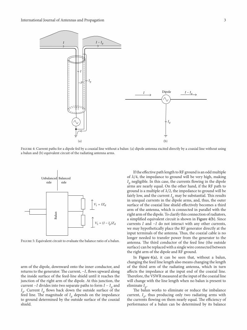

International Journal of
AerospaceEngineeringHindawi Publishing Corporationhttpwwwhindawicom Volume 2014
RoboticsJournal of
Hindawi Publishing Corporationhttpwwwhindawicom Volume 2014
Hindawi Publishing Corporationhttpwwwhindawicom Volume 2014
Active and Passive Electronic Components
Control Scienceand Engineering
Journal of
Hindawi Publishing Corporationhttpwwwhindawicom Volume 2014
International Journal of
RotatingMachinery
Hindawi Publishing Corporationhttpwwwhindawicom Volume 2014
Hindawi Publishing Corporation httpwwwhindawicom
Journal ofEngineeringVolume 2014
Submit your manuscripts athttpwwwhindawicom
VLSI Design
Hindawi Publishing Corporationhttpwwwhindawicom Volume 2014
Hindawi Publishing Corporationhttpwwwhindawicom Volume 2014
Shock and Vibration
Hindawi Publishing Corporationhttpwwwhindawicom Volume 2014
Civil EngineeringAdvances in
Acoustics and VibrationAdvances in
Hindawi Publishing Corporationhttpwwwhindawicom Volume 2014
Hindawi Publishing Corporationhttpwwwhindawicom Volume 2014
Electrical and Computer Engineering
Journal of
Advances inOptoElectronics
Hindawi Publishing Corporation httpwwwhindawicom
Volume 2014
The Scientific World JournalHindawi Publishing Corporation httpwwwhindawicom Volume 2014
SensorsJournal of
Hindawi Publishing Corporationhttpwwwhindawicom Volume 2014
Modelling amp Simulation in EngineeringHindawi Publishing Corporation httpwwwhindawicom Volume 2014
Hindawi Publishing Corporationhttpwwwhindawicom Volume 2014
Chemical EngineeringInternational Journal of Antennas and
Propagation
International Journal of
Hindawi Publishing Corporationhttpwwwhindawicom Volume 2014
Hindawi Publishing Corporationhttpwwwhindawicom Volume 2014
Navigation and Observation
International Journal of
Hindawi Publishing Corporationhttpwwwhindawicom Volume 2014
DistributedSensor Networks
International Journal of