
Research Article...
14
Hindawi Publishing Corporation Journal of Electrical and Computer Engineering Volume 2010, Article ID 706464, 13 pages doi:10.1155/2010/706464 Research Article Iterative Processing for Superposition Mapping Tianbin Wo, Meelis Noemm, Dapeng Hao, and Peter Adam Hoeher Information and Coding Theory Laboratory, University of Kiel, Kaiserstrasse 2, 24143 Kiel, Germany Correspondence should be addressed to Tianbin Wo, [email protected] Received 12 March 2010; Accepted 27 June 2010 Academic Editor: Christian Schlegel Copyright © 2010 Tianbin Wo et al. This is an open access article distributed under the Creative Commons Attribution License, which permits unrestricted use, distribution, and reproduction in any medium, provided the original work is properly cited. Superposition mapping (SM) is a modulation technique which loads bit tuples onto data symbols simply via linear superposition. Since the resulting data symbols are often Gaussian-like, SM has a good theoretical potential to approach the capacity of Gaussian channels. On the other hand, the symbol constellation is typically nonbijective and its characteristic is very different from that of conventional mapping schemes like QAM or PSK. As a result, its behavior is also quite different from conventional mapping schemes, particularly when applied in the framework of bit-interleaved coded modulation. In this paper, a comprehensive analysis is provided for SM, with particular focus on aspects related to iterative processing. 1. Introduction According to Shannon’s information theory, the capacity of a Gaussian channel corresponds to the maximum mutual information between channel inputs and outputs [1, 2]. Given a power constraint, this maximum can be achieved if and only if the channel inputs are Gaussian distributed. Since Shannon’s seminal work in 1948, many approaches have been proposed to map binary bits onto Gaussian- like distributed symbols. Among these approaches, the most well-known ones are Huffman decoding [3] and signal shaping [4]. By using a Huffman decoder to map bits onto a signal constellation with a well-designed distribution, for example, the Maxwell-Boltzmann distribution [5], one can maximize the mutual information between channel input and output for a given symbol cardinality and average power. Unfortunately, this approach demands variable-rate transmission and is consequently undesirable for practical applications. In contrast, signal shaping techniques are fixed- rate transmission schemes and for this reason have attracted interest in the field of real-world implementations. There are two popular methods for signal shaping, namely trellis shaping [6] and shell mapping [7, 8]. Both trellis shaping and shell mapping share a common idea, that is to construct a high-dimensional uniform constellation which results in low-dimensional nonuniform constituent constellations. They are both able to deliver a shaping gain of about 1.0dB [9] without any additional effort with respect to channel coding, but subject to the assumption of noniterative demapping and decoding. In case of iterative soft-in soft-out (SISO) demapping and decoding, the block-wise mapping manner inherent in popular shaping techniques presents a bottleneck to the design of receiver algorithms. To overcome the drawbacks of Huffman decoding and signal shaping, several researchers proposed different transmission schemes employing linear superposition to generate Gaussian-like symbols [10–12]. Without loss of generality, we denote the key component of such techniques as superposition mapping (SM). The characteristic feature of SM is that the conversion from binary bits to data symbols is done by a certain form of superposition instead of bijective (one-to-one) mapping. Since the output of a superposition mapper is often Gaussian-like, the necessity of doing active signal shaping is eliminated. On the other hand, superimposed signal components interfere with each other, and the resulting relationship between bit tuples and data symbols is often nonbijective. To guarantee a perfect reconstruction at the receiver side, channel coding and interleaving are typically mandatory, and iterations between the decoder and demapper are essential. This incurs a structure well known as bit-interleaved coded modulation (BICM) [13]. For an easy reference, we may call such a transmission technique bit-interleaved coded modulation with superposition mapping (BICM-SM).
Transcript of Research Article...

Hindawi Publishing CorporationJournal of Electrical and Computer EngineeringVolume 2010, Article ID 706464, 13 pagesdoi:10.1155/2010/706464
Research Article
Iterative Processing for Superposition Mapping
Tianbin Wo, Meelis Noemm, Dapeng Hao, and Peter Adam Hoeher
Information and Coding Theory Laboratory, University of Kiel, Kaiserstrasse 2, 24143 Kiel, Germany
Correspondence should be addressed to Tianbin Wo, [email protected]
Received 12 March 2010; Accepted 27 June 2010
Academic Editor: Christian Schlegel
Copyright © 2010 Tianbin Wo et al. This is an open access article distributed under the Creative Commons Attribution License,which permits unrestricted use, distribution, and reproduction in any medium, provided the original work is properly cited.
Superposition mapping (SM) is a modulation technique which loads bit tuples onto data symbols simply via linear superposition.Since the resulting data symbols are often Gaussian-like, SM has a good theoretical potential to approach the capacity of Gaussianchannels. On the other hand, the symbol constellation is typically nonbijective and its characteristic is very different from thatof conventional mapping schemes like QAM or PSK. As a result, its behavior is also quite different from conventional mappingschemes, particularly when applied in the framework of bit-interleaved coded modulation. In this paper, a comprehensive analysisis provided for SM, with particular focus on aspects related to iterative processing.
1. Introduction
According to Shannon’s information theory, the capacity ofa Gaussian channel corresponds to the maximum mutualinformation between channel inputs and outputs [1, 2].Given a power constraint, this maximum can be achievedif and only if the channel inputs are Gaussian distributed.Since Shannon’s seminal work in 1948, many approacheshave been proposed to map binary bits onto Gaussian-like distributed symbols. Among these approaches, the mostwell-known ones are Huffman decoding [3] and signalshaping [4]. By using a Huffman decoder to map bits ontoa signal constellation with a well-designed distribution, forexample, the Maxwell-Boltzmann distribution [5], one canmaximize the mutual information between channel inputand output for a given symbol cardinality and averagepower. Unfortunately, this approach demands variable-ratetransmission and is consequently undesirable for practicalapplications. In contrast, signal shaping techniques are fixed-rate transmission schemes and for this reason have attractedinterest in the field of real-world implementations. Thereare two popular methods for signal shaping, namely trellisshaping [6] and shell mapping [7, 8]. Both trellis shapingand shell mapping share a common idea, that is to constructa high-dimensional uniform constellation which resultsin low-dimensional nonuniform constituent constellations.They are both able to deliver a shaping gain of about
1.0 dB [9] without any additional effort with respect tochannel coding, but subject to the assumption of noniterativedemapping and decoding. In case of iterative soft-in soft-out(SISO) demapping and decoding, the block-wise mappingmanner inherent in popular shaping techniques presents abottleneck to the design of receiver algorithms.
To overcome the drawbacks of Huffman decodingand signal shaping, several researchers proposed differenttransmission schemes employing linear superposition togenerate Gaussian-like symbols [10–12]. Without loss ofgenerality, we denote the key component of such techniquesas superposition mapping (SM). The characteristic featureof SM is that the conversion from binary bits to datasymbols is done by a certain form of superposition insteadof bijective (one-to-one) mapping. Since the output of asuperposition mapper is often Gaussian-like, the necessityof doing active signal shaping is eliminated. On the otherhand, superimposed signal components interfere with eachother, and the resulting relationship between bit tuples anddata symbols is often nonbijective. To guarantee a perfectreconstruction at the receiver side, channel coding andinterleaving are typically mandatory, and iterations betweenthe decoder and demapper are essential. This incurs astructure well known as bit-interleaved coded modulation(BICM) [13]. For an easy reference, we may call such atransmission technique bit-interleaved coded modulationwith superposition mapping (BICM-SM).

2 Journal of Electrical and Computer Engineering
In this paper, we provide a comprehensive study on theperformance of BICM-SM, with particular focus on aspectsrelated to iterative demapping and decoding. Theoretical aswell as numerical results are provided. Via mutual informa-tion analysis, the capacity-achieving potential of superpo-sition mapping is demonstrated. Due to the superimposedsignal structure and the nonuniform signal distribution, therequirements of a superposition mapper on the channel codeare essentially different from that of a uniform bijectivemapper like PSK/QAM. Through EXIT chart analysis, wewill show that repetition coding is in fact superior for codedSM systems. In addition to these analytical investigations,two practical issues are also considered. A novel tree-pruningconcept is proposed to reduce the demapping complexity,and a baseband clipping scheme together with an iterativesoft compensation mechanism is presented to reduce thesignal peak-to-average power ratio (PAPR), while keepingthe system performance degradation at an acceptable level.
The remainder of this paper is organized as follows.Section 2 introduces the Gaussian channel model underinvestigation. Section 3 provides a brief description ofsuperposition mapping and related information theoreticalaspects. Section 4 treats the application of superpositionmapping in the framework of bit-interleaved coded mod-ulation. In Section 5, an extensive study is carried out oniterative demapping and decoding process of coded SMsystems. Particular focus is put on the convergence behaviorof the iterative receiver given different channel codes. InSection 6, several approaches for low-complexity demappingare discussed, and in Section 7 a novel method for PAPRcontrol is proposed. Finally, Section 8 summarizes the paperand suggests some interesting topics for future work.
2. Gaussian Channel
The additive white Gaussian noise (AWGN) channel isperhaps the most important channel model with continuousoutputs. Though simple, it models the fundamental effectsof communication in a noisy environment. The discrete-timecomplex AWGN channel model can be written as
y[k] = x[k] + z[k], z[k] ∼ CN(0, σ2
z
), (1)
where k is the time index. The mutual information betweenthe channel input and output is given by
I(x; y
) = h(y)− h
(y | x) = h
(y)− h(z), (2)
where h(·) denotes differential entropy. Since the normaldistribution maximizes the entropy for a given variance,the maximum of I(x; y) is achieved when y is Gaussiandistributed. Strictly speaking, y can only be Gaussian ifx is Gaussian. In practice, however, it often suffices if xis Gaussian-like, given a reasonable signal-to-noise ratio(SNR).
3. Superposition Mapping
Figure 1 shows the general structure of superposition map-ping. After serial-to-parallel (S/P) conversion, each code bit
S/P
BPSK
BPSK
BPSK
b1
bn
bN
d1
dn
dN
α1e jθ1
αne jθn
αNe jθN
∑
c1
cn
cN
x
×
×
×
...
...
Figure 1: Superposition mapping (SM).
bn is first converted into a binary antipodal symbol dn. (Dueto superposition mapping, binary antipodal componentsymbols bring no limit with respect to the overall bandwidthefficiency.) Then, power allocation and phase allocation areperformed. Afterwards, the complex component symbols cn(called “chips”) are linearly superimposed to create a finite-alphabet data symbol. SM can be described by the followingequation:
x =N∑
n=1
cn =N∑
n=1
dnαnejθn , dn ∈ {±1}, (3)
where N is called the bit load of the superposition mapper.By tuning the amplitudes αn and the phases θn, differentsuperposition mapping schemes can be obtained. In case ofequal power allocation, that is, when all amplitudes αn arethe same, all bits bn are equally protected. It was shownin [14] that, given a BICM system with standard codingapproaches, direct superposition mapping (DSM) with equalpower allocation suffers from limited supportable bandwidthefficiency, and DSM with unequal power allocation suffersfrom power efficiency degradation. In contrast, phase-shiftedsuperposition mapping (PSM) provides virtually unlimitedsupportable bandwidth efficiency and desirable power effi-ciency. For this reason, this paper will exclusively focus onPSM, while most of the analysis can easily be extended to thecase of DSM.
3.1. Phase-Shifted Superposition Mapping. PSM is character-ized by the following power and phase allocation:
αn = α for 1 ≤ n ≤ N ,
θn = π(n− 1)N
for 1 ≤ n ≤ N.(4)
All chips are allocated with the same magnitude, and eachchip is allocated with a unique phase uniformly drawn overthe interval [0,π). Substituting (4) into (3), we obtain
Re{x} =N∑
n=1
Re{cn} =N∑
n=1
αdn cos(π(n− 1)
N
),
Im{x} =N∑
n=1
Im{cn} =N∑
n=1
αdn sin(π(n− 1)
N
).
(5)

Journal of Electrical and Computer Engineering 3
Since |cn|2 ≡ α2, the total energy spent for each bit isconstant. Hence, PSM is characterized by a high powerefficiency provided by superposition mapping with equalpower allocation. On the other hand, from (5) one can seethat unequal power allocation is actually done in the realand imaginary dimension, respectively, due to the individualphase shift. This increases the cardinality of the outputsymbol and greatly enhances the supportable bandwidthefficiency. As a consequence, PSM does not suffer fromlimited supportable bandwidth efficiency.
Figure 2 illustrates the PSM constellation for differentbit loads, and Figure 3 shows the probability distributionof one quadrature component of the PSM outputs. ForN = 4, the PSM constellation looks like circular 16-QAM, while for larger N , the constellation points tendto be geometrically Gaussian-like distributed. (The centrallimit theorem cannot be applied here, since {c1, . . . , cN} areindependent but not identically distributed due to individualphase shifts.) It can be easily proven that the real part and theimaginary part of x are statistically independent. Therefore,the constellation points of PSM are approximately circularGaussian distributed, though in no case perfect.
3.2. An Information Theoretical View. Given the distributionof x, the mutual information (MI) I(x; y) can be numericallyevaluated. Figure 4 provides MI curves for PSM as well asfor square QAM. Comparing Figure 4(a) with Figure 4(b),it can be seen that PSM outperforms QAM in the leftregion, and it is almost capacity achieving, which is dueto the Gaussian-like symbol distribution. The gap betweenthe capacity curve and the slope for high-order QAM inFigure 4(b) corresponds to the ultimate shaping gain [9].On the other hand, PSM is worse than QAM in the rightregion, which is due to a smaller minimum distance betweendistinct constellation points. Last but not least, in mostcases, PSM and QAM provide roughly the same entropyper symbol, given an identical bit load N , which can beseen by comparing the smooth sections of the MI curves.An important message from the above observations is that,with PSM, signal shaping is no longer necessary to approachthe capacity of the Gaussian channel. As a matter of fact,the mutual information given PSM input symbols can bearbitrarily close to the capacity at any SNR, as long as thebit load N is large enough.
3.3. Rate Limit of PSM. Following (1), the limit of codingrate for PSM transmission over the AWGN channel is givenby
R � I(x; y
)
N� H(x)
N� 1. (6)
Hence, the bandwidth efficiency of PSM is virtually unlim-ited and the required spreading factor (1/R) should notbe very large. The bandwidth efficiency limit at about2 bits/symbol per signal dimension reported in [15] isin fact due to the adopted Gaussian-approximation-baseddemapping algorithm rather than the mapping scheme itself.
4. Bit-Interleaved Coded Modulation withSuperposition Mapping
Bit-interleaved coded modulation [13] is widely recognizedas a promising technique to approach the channel capacity athigh SNRs. Typically, higher-order QAM is used to achievea high bandwidth efficiency, while an interleaver is placedbetween the encoder and the signal mapper to exploit thebit diversity of QAM. With the same structure but replacingQAM with superposition mapping (SM), we obtain theBICM-SM transmission scheme under investigation.
4.1. General Structure. Figure 5 shows the transmitter andreceiver structure of BICM-SM, where SD stands for super-position demapping. Since a superposition mapper is oftena nonbijective (many-to-one) mapper, iterations betweenthe demapper and the decoder are not only necessary butmandatory. A superposition demapper usually can not workproperly without utilizing the redundancy introduced bythe channel code. This is quite different in comparisonwith the demapper of conventional mapping schemes, likea PSK/QAM demapper, which does not necessarily have tocooperate with the channel decoder.
4.2. Soft-In Soft-Out Demapping. The superposition demap-per needs to provide soft decisions of each code bit giventhe channel outputs and the a priori information from thedecoder. Given an AWGN channel, an APP soft-input soft-output (SISO) demapper for SM can be described as follows.Let
b∼n.= [b1, b2, . . . , bn−1, bn+1, . . . , bN ] (7)
collect the bits excluding bn loaded on one symbol, we have
LLR(bn).= ln
p(y | bn = 0
)
p(y | bn = 1
)
= ln
∑b∼n p
(y | bn = 0, b∼n
)P(b∼n)
∑b∼n p
(y | bn = 1, b∼n
)P(b∼n)
,
(8)
where
P(b∼n) =N∏
i=1,i /=n
P(bi), (9)
assuming statistical independence of interleaved code bits.The APP demapping algorithm, in spite of its high complex-ity, is the first choice for theoretical analyses, as it providesthe best performance. In the following measurements, APPdemapping is applied, if not specifically addressed.
5. Iterative Processing forSuperposition Mapping
Due to the geometrically nonuniform symbol distribution,we observe that PSM is better than square QAM in thesense of mutual information over the Gaussian channel. Aslong as the bit load N is large enough, PSM can efficiently

4 Journal of Electrical and Computer Engineering
−2.5 −1.5 −0.5 0.5 1.5 2.5−2.5
−1.5
−0.5
0.5
1.5
2.5
Qu
adra
ture
In-phase
(a) N = 4
−2.5 −1.5 −0.5 0.5 1.5 2.5−2.5
−1.5
−0.5
0.5
1.5
2.5
Qu
adra
ture
In-phase
(b) N = 8
−2.5 −1.5 −0.5 0.5 1.5 2.5−2.5
−1.5
−0.5
0.5
1.5
2.5
Qu
adra
ture
In-phase
(c) N = 12
Figure 2: Constellation diagrams for PSM, α = √1/N .
−2 0 20
0.05
0.15
0.25
0.1
0.2
0.3
Pro
babi
lity
In-phase
(a) N = 4
−2 0 20
0.05
0.15
0.1
Pro
babi
lity
In-phase
(b) N = 8
0
0.02
0.04
0.06
0.08
0.1
−2 0 2P
roba
bilit
y
In-phase
(c) N = 12
Figure 3: Distribution of Re{x} for PSM, α = √1/N .
fill up the 1.53 dB gap, well known as the ultimate shapinggain in the terminology of signal shaping, between thechannel capacity and the mutual information with uniformsignalling. Nevertheless, due to linear superposition withequal power allocation, the behavior of a PSM demapper,in the scenario of iterative demapping and decoding is verydifferent from that of a demapper of conventional mappingschemes like PSK/QAM. This in fact implies some differentconcepts for the code design. In this section, we will havean in-depth study on the iterative demapping and decodingprocess of coded PSM systems via an EXIT chart analysis[16, 17].
5.1. First Impression on the Performance. To start, let us firsthave a look at the performance of coded PSM. We considertwo type of codes, low-density parity check (LDPC) codes,which are known to be capacity-achieving for binary-inputGaussian channels, and repetition codes, considered to beweak codes as they provide no coding gain at all on theAWGN channel. As shown in Figure 6, the true situationis in fact opposite to the common understanding, that is,repetition-coded PSM can even outperform LDPC-codedPSM, particularly at large bit loads N . Another noteworthyphenomenon is that the performance of LDPC-coded PSMdegrades severely as the bit load N increases. All these
observations indicate that the classical purely parity-check-based channel codes do not really fit with a superpositionmapper, which is to be studied in the next sections.
5.2. MI Transfer Characteristics of APP Demapper. To startan analysis on PSM, we will have a look at the mutualinformation (MI) transfer characteristics of the SISO APPdemapper. Square QAM with Gray labeling will be used asreference for comparison.
Let us begin the discussion with the starting points inthe left side of Figure 7. Compared to PSM, QAM with Graylabeling has considerably higher starting points, given thesame bit load. The starting points show how reliable will bethe output of the demapper given only the channel outputand no a priori information from the decoder. For PSMwith large N , the starting points are very low. Hence, thedemapper output in the first iteration(s) is very weak. Thiscomes from the fact that the constellation diagram, Figure 2,is densely populated in the central region, which leads toa reduced minimum distance and in some cases even tononbijective mapping. This effect can be clearly observedin Figure 7(b) for both PSM and QAM, where the startingpoints improve as the SNR increases.
The slope of the curves presents the most obviousdifference. For QAM with Gray labeling, the curves are

Journal of Electrical and Computer Engineering 5
0 5 10 15 20 25 30 35 40 45 50
Es/N0 (dB)
0
1
2
3
4
5
6
7
8
9
10
11
12
Mu
tual
info
rmat
ion
(bit
s/sy
mbo
l)
(a) PSM
0 5 10 15 20 25 30 35 40 45 50
Es/N0 (dB)
0
1
2
3
4
5
6
7
8
9
10
11
12
Capacity
Ultimate shaping gain1.53 dB
N = 2N = 4N = 6
N = 8N = 10
N = 12
Mu
tual
info
rmat
ion
(bit
s/sy
mbo
l)
(b) QAM
Figure 4: Mutual information of PSM/QAM over the AWGNchannel.
more or less horizontal, with modest slopes for N ≥ 8.On the other hand, for PSM the curves have steep slopes,excluding N = 2. For N > 6, the curves are even convex.The slope of the curves characterizes the importance orusefulness of iterations. Hence in case of PSM, as thefeedback from the decoder becomes more reliable fromiteration to iteration, the demapper output improves. Onthe contrary for QAM, usually only a few iterations aresufficient and the gain by feedback of extrinsic informationis noticeably smaller.
At last we come to the ending points of the MI transferplots. Figure 7(a) presents an interesting fact. In the case ofPSM, given the same Ec/N0, for all selections of N , the curvesend in the same point. This relates to the fact that all code bitsare converted to binary antipodal symbols. If the feedbackinformation is very reliable, then we are left with a detectionscenario for BPSK transmission over a Gaussian channel. ForQAM, the ending points differ significantly and for N > 2
ENC
DEC
Ext
rin
sic
π−1
π
y
SMπ
AWGN
x
SD
Figure 5: Bit-interleaved coded modulation with superpositionmapping.
0 4 16 20 24 28 32 36
Eb/N0 (dB)
10−6
10−5
10−4
10−3
10−2
10−1
100
Bit
erro
rra
te
8 12
LDPC, N = 2LDPC, N = 4LDPC, N = 6LDPC, N = 8LDPC, N = 10LDPC, N = 12
Repetition, N = 2Repetition, N = 4Repetition, N = 6Repetition, N = 8Repetition, N = 10Repetition, N = 12
Figure 6: BER performance of PSM with rate 1/2 (3, 6)-regularLDPC codes and rate 1/2 regular repetition codes.
the points are always lower than the corresponding ones forPSM. This can be explained by the fact that for QAM bits areunequally protected.
5.3. Convergence Behavior of Coded PSM. For coded modu-lation, an important issue is the convergence of the iterativedemapping and decoding process. Whether an iterativereceiver can converge or not is determined by the channelSNR and, more importantly, by the relation between thedecoder characteristics and the demapper characteristics.As a commonly used tool, an EXIT chart can elegantlydemonstrate the suitability of a channel code for a givensignal mapper. By means of an EXIT chart analysis, wewill see that there is indeed a strong reason for the goodperformance of repetition-coded PSM systems, and we willalso see that the requirements of superposition mappingon channel codes are essentially different with respect toconventional mapping schemes.

6 Journal of Electrical and Computer Engineering
0
0.2
0.4
0.6
0.8
1
1IA
0 0.2 0.4 0.6 0.8
I E
N = 2N = 4N = 6
N = 8N = 10
N = 12
(a) Ec/N0 = 5 dB
0
0.2
0.4
0.6
0.8
1
1IA
0 0.2 0.4 0.6 0.8
I E
−5 dB
10 dB
15 dB20 dB25 dB
0 dB5 dB
(b) N = 12
Figure 7: MI transfer characteristics of PSM demapper (solid lines)and that of Gray labeled QAM demapper (dashed lines).
Let us assume that the SNR per code bit is Ec/N0 =10 dB and the bit load is N = 12. Given this setup, the MItransfer curve of a PSM demapper is plotted as a dasheddot curve in Figure 8. The MI transfer curves for severaldecoders are also plotted, with the horizontal and verticalaxes swapped. To guarantee convergence, the MI transfercurve of the decoder must be below the MI transfer curve ofthe demapper, so as to open the tunnel for iterative refiningof the soft decisions. Otherwise, the iterative process will getstuck at a certain point and no additional gain is achievableby further iterations.
As one can see from Figure 8, given a regular LDPC codewith column weight 3, one needs to drop the code rate to aslow as 1/6 in order to open the tunnel. The main problem
0
0.2
0.4
0.6
0.8
1
10 0.2 0.4 0.6 0.8
PSMdemapper
I E,D
EM
,IA
,DE
C
LDPC, R = 1/2
LDPC, R = 1/3
LDPC, R = 1/4
LDPC, R = 1/6
Rep., R= 1/2
Rep., R= 1/3
IA,DEM, IE,DEC
Figure 8: EXIT chart for coded PSM, N = 12, Ec/N0 = 10 dB.
is in the left region. As already explained in Section 5.2, theMI transfer curve of a PSM demapper with large N startsfrom a rather low point but ends at a rather high point.Meanwhile, the MI transfer curve of an LDPC code alwayspossesses a wide quasi-flat section, mainly due to the natureof parity checks. This situation makes the tunnel difficult toopen in the left region but often unnecessarily wide in theright region, which clearly explains the poor performance ofLDPC-coded PSM at large bit loads N , as shown in Figure 6.As a matter of fact, the classical strong codes, such as Turbocodes and LDPC codes, purely built upon parity checks, donot fit with PSM very well. To fully exploit the capacity-achieving potential of superposition mapping, new codesand new code design concepts are necessary. Neverthelessby checking Figure 7(b) carefully, one recognizes that the MItransfer characteristics of LDPC codes perfectly match withthat of QAM, which explains the excellent performance ofLDPC-coded QAM systems.
In contrast to parity-check-based codes, a simple rate 1/2repetition code can already effectively open the tunnel forconvergence, which can also be validated by the good perfor-mance of repetition-coded PSM in Figure 6. Repetition codescome with zero coding gain, in the sense that lowering theending point of the MI transfer curve is only possible via anequivalent amount of degradation in the Ec/N0. Nevertheless,due to the special property of PSM, this issue does notpresent a big problem. For reasonable SNRs, the MI transfercurves of PSM always end at a very high point. Note that,for PSM with large bit loads, the primary task of channelcoding is no longer to combat the additive noise but toguarantee the separation of superimposed binary chips. Aslong as all chips are perfectly separated, the BER performanceof PSM will asymptotically approach that of BPSK, whilethe performance of uncoded BPSK is already very goodat Ec/N0 = 10 dB. Above all, the difficult part is the firstfew iterations. A decoder has to be able to deliver reliablefeedback given very weak inputs in order to let the iterativedemapping and decoding go on properly. With respect to thisconcern, however, a repetition code is the best choice. Onemay call the checks of a repetition code as equality checks.

Journal of Electrical and Computer Engineering 7
0 2 4 6 8 10 12 14 16 18 20 22 24 26 2810−6
10−5
10−4
10−3
10−2
10−1
100
Bit
erro
rra
te
Shannon limit LDPC, 4096-QAMUncoded 64-QAM
Eb/N0 (dB)
Repetition, N = 12 PSM
Figure 9: BER versus Eb/N0, bandwidth efficiency 6 bits/symbol,rate 1/2 repetition code, and rate 1/2 (6000, 12000, 3, 6)-regularLDPC code.
There is effectively only one info bit involved in each equalitycheck. As a result, the feedback information of an equalitycheck can be as strong as needed at the very beginningof iterative processing, if the coding rate is low enough,illustrated by the MI transfer curve of a rate 1/3 repetitioncode in Figure 8. Note that the MI transfer curve of the PSMdemapper is often concave, which creates a severe problemfor parity-check-based codes, but this is not a problem forrepetition codes, because the curves for repetition codesare also concave for R < 1/2. Therefore, although a purerepetition code cannot be optimal for PSM, it is definitelya good choice among others.
To locate the performance of repetition-coded PSM, wecompare it to several systems with the same bandwidthefficiency in Figure 9. For an information rate of 6 bitsper channel symbol, uncoded 64-QAM has a distance ofabout 9 dB to the Shannon limit, while a rate 1/2 LDPC-coded 4096-QAM system shortens this distance by 3 dB. Incomparison, rate 1/2 repetition-coded PSM with N = 12is in fact just 3 dB away from the Shannon limit, in spiteof zero coding gain. Although the codes for both PSM andQAM have not yet been optimized, these results give a roughimpression about their relative performance.
6. Alternative Demappers
APP demapping is a good choice for system analysis butthe computational complexity is very high. Hence, twoalternative demappers are brought out and a brief analysisis given.
6.1. Gaussian Approximation Approach. The Gaussianapproximation (GA) is well known from multiusersystems. This concept has been widely used in multiple-access/multiplexing systems [18, 19]. The main idea is that
P(c2 = α2) ∗
P(c3 = α3) ∗
P(c1 = α1) ∗
∗ P(c2 = −α2)
P(s0) = 1
∗ P(c1 = −α1)
Pruned
Figure 10: Illustration of the update of a priori values and thepruning concept.
the interfering superimposed symbols, together with theGaussian noise
vn = y − cn =N∑
i=1,i /=n
ci + z, (10)
are approximated by a single Gaussian random variable.Hence, the LLR of cn can be obtained via
LLR(cn).= ln
p(y | cn = +αn
)
p(y | cn = −αn
)
≈ −(y − αn − μvn
)2
σ2vn
+
(y + αn − μvn
)2
σ2vn
= 4 · Re{α∗n ·
(y − μvn
)}
σ2vn
,
(11)
where the mean and variance of the interfering signalare updated by feedback information from the decoder.According to the turbo principle, as the feedback infor-mation improves from iteration to iteration, the demapperestimates get more reliable. The complexity increases linearlywith the bit load N , which makes Gaussian approximationvery attractive for practical implementations. However, theapproximation is not always good enough and can severelylimit the performance. Details on this will be given inSection 6.5.
6.2. Tree-Based Approach. In [12], SM is modelled by atree diagram. Since a tree diagram is a special case ofa Markov process, the Bahl-Cocke-Jelinek-Raviv (BCJR)algorithm [20] can be used for SISO demapping of SM toreduce the computational complexity. Let sn denote the stateat the nth level. By the property of superposition mapping,the relationship between the states of two neighboring levelsis simply given by
sn = sn−1 + cn. (12)
The a priori distribution of the states is evaluated recursivelyaccording to
P(sn) =∑
cn
P(sn−1 = sn − cn)P(cn) (13)

8 Journal of Electrical and Computer Engineering
through the tree by propagating the values from root toleaves. The a priori information is given via the branches tothe lower level and multiplied with the corresponding chipprobability, as illustrated in Figure 10. Now, the extrinsic LLRof the nth chip can be obtained via
LLR(cn).= ln
p(y | cn = +αn
)
p(y | cn = −αn
)
= ln
∑sn−1
p(y | sn = sn−1 + αn
)P(sn−1)
∑sn−1
p(y | sn = sn−1 − αn
)P(sn−1)
.
(14)
The likelihood of the received value given the state at the nthlevel can be calculated by a backward recursion through thetree. Starting from the leaves,
p(y | sN
) = 1πσ2
zexp
(∣∣y − sN
∣∣2
σ2z
)
, (15)
one calculates p(y | sn) recursively by adding togetherthe likelihood values from the branches that have beenmultiplied with the corresponding chip probabilities. Thisapproach cleverly utilizes the probability propagation andhence considerably reduces the computational complexity.However, the complexity is still exponentially increasing.Inspired by the tree structure, we would like to introduce anovel method of how to reduce the size of the tree withoutbig sacrifices concerning the performance.
6.3. Pruned Tree-Based Approach. The core idea is based onthe fact that if at some level of the tree two nodes are closeto each other, then during the subsequent tree expansion thecorresponding subtrees will always keep the distance relation.(This means that the superposition values for nodes aresimilar.) In other words, the two subtrees are the same, justone is a shifted version of the other. In the special case thattwo nodes have exactly the same superposition value, thenthe subtrees are identical. Such subtrees are redundant andcan be pruned. Figure 10 illustrates one possible mergingscenario. Considering the demapping process, nothing ischanged. All the bit paths still exist, the only differencecompared to the full tree is that all pruned node valuesare shifted by a certain constant. In order to control thepruning rate (and hence the computational complexity), weintroduce a merging threshold and denote it by ε. Nowstarting from the root, for every level the squared differencevalues of all nodes are checked if they fulfil
∣∣∣sin − s
jn
∣∣∣
2< ε, (16)
where sin and sjn denote two node values from that level. If
two nodes are in the range of ε, then sjn is merged to sin
and pruned. With a single merging operation actually 2N−n
constellation point pairs are merged, that differ by sin − sjn,
because a node at level n, if expanded, would relate to 2N−n
leaves. Hence, the tree is reduced by the given sub-tree from
node sjn to the leaves, resulting in 2N−n+1 − 1 pruned nodes.
Once the whole tree is processed, all nodes in the range of εare merged and the tree will be stored for permanent use.
−αi+αi
d′+αi+1
−αi+1
Figure 11: Distance between bit sequences “01” and “10”.
Table 1: Complexity reduction of the tree with given ε.
N ε Total nodes Nodes left |X′|6 0.1786 127 100 42
8 0.0761 511 258 90
10 0.0391 2047 634 196
12 0.0227 8191 1678 468
14 0.0143 32767 3303 804
16 0.0096 131071 6269 1364
However, there are a few problems. First, with multiplemergers, a node may drift quite far from its original value,maximally by
max(d) < ε · (N − n + 1), (17)
if the remained node always gets merged to another node.The second issue comes from detection. After pruningthe tree, some constellation points do not exist in thetree anymore. Hence, given a cut symbol is transmitted,an increased SNR will not lead to a better demappingperformance, as such signal point does not exist in the treeanymore. To overcome this problem, we should adjust thetransmitter to fit to the receiver. Therefore, the same prunedtree should be used to select the transmit symbol, given thecoded bits. One takes N coded bits and follows the treefrom root to leaf, while choosing the branch according tothe bit. This way the ambiguity between the mapper anddemapper is removed, as both sides are working with thesame constellation space.
The parameter ε gives a certain freedom to balancebetween complexity and performance. Clearly if one wouldprune the tree too much, the performance would degradesignificantly. From simulations, a certain point was foundafter that catastrophic merging takes place. This happens ifε is large enough so that any code bit sequences, “01” and“10”, for any N , get merged. The distance d′ between thesetwo bit sequences is shown in Figure 11 by the dashed line.
Hence, to avoid such short span mergers, ε should bechosen smaller than d′2. Given the amplitude factor α =1/√N , the boundary values are listed in Table 1. The formula
to calculate d′2 for a fixed N is
d′2 = (2(cn − cn+1))2
= 4(α cos
(π(n− 1)
N
)− α cos
(πn
N
)
+ α sin(π(n− 1)
N
)− α sin
(πn
N
))2
.
(18)
The node reduction is significant. For N = 16 alreadyapproximately 95% of the tree is pruned and the rate
Journal of Electrical and Computer Engineering 9
−2 0 20
0.05
0.15
0.25
0.1
0.2
0.3
Pro
babi
lity
In-phase
(a) N = 4
−2 0 20
0.05
0.15
0.1
Pro
babi
lity
In-phase
(b) N = 8
0
0.02
0.04
0.06
0.08
0.1
−2 0 2
Pro
babi
lity
In-phase
(c) N = 12
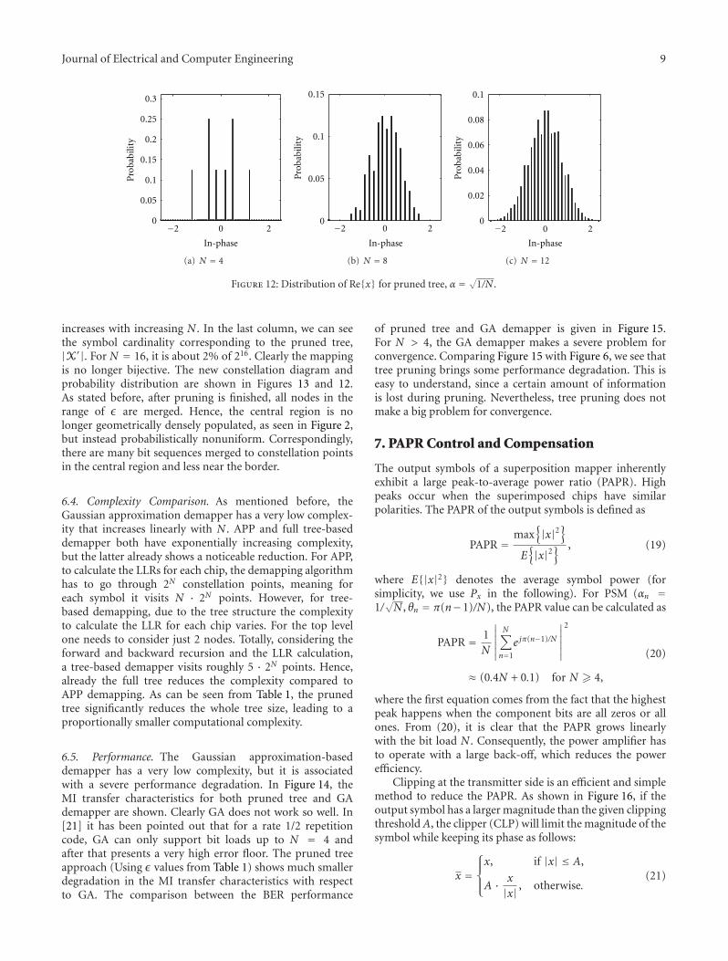
Figure 12: Distribution of Re{x} for pruned tree, α = √1/N .
increases with increasing N . In the last column, we can seethe symbol cardinality corresponding to the pruned tree,|X′|. For N = 16, it is about 2% of 216. Clearly the mappingis no longer bijective. The new constellation diagram andprobability distribution are shown in Figures 13 and 12.As stated before, after pruning is finished, all nodes in therange of ε are merged. Hence, the central region is nolonger geometrically densely populated, as seen in Figure 2,but instead probabilistically nonuniform. Correspondingly,there are many bit sequences merged to constellation pointsin the central region and less near the border.
6.4. Complexity Comparison. As mentioned before, theGaussian approximation demapper has a very low complex-ity that increases linearly with N . APP and full tree-baseddemapper both have exponentially increasing complexity,but the latter already shows a noticeable reduction. For APP,to calculate the LLRs for each chip, the demapping algorithmhas to go through 2N constellation points, meaning foreach symbol it visits N · 2N points. However, for tree-based demapping, due to the tree structure the complexityto calculate the LLR for each chip varies. For the top levelone needs to consider just 2 nodes. Totally, considering theforward and backward recursion and the LLR calculation,a tree-based demapper visits roughly 5 · 2N points. Hence,already the full tree reduces the complexity compared toAPP demapping. As can be seen from Table 1, the prunedtree significantly reduces the whole tree size, leading to aproportionally smaller computational complexity.
6.5. Performance. The Gaussian approximation-baseddemapper has a very low complexity, but it is associatedwith a severe performance degradation. In Figure 14, theMI transfer characteristics for both pruned tree and GAdemapper are shown. Clearly GA does not work so well. In[21] it has been pointed out that for a rate 1/2 repetitioncode, GA can only support bit loads up to N = 4 andafter that presents a very high error floor. The pruned treeapproach (Using ε values from Table 1) shows much smallerdegradation in the MI transfer characteristics with respectto GA. The comparison between the BER performance
of pruned tree and GA demapper is given in Figure 15.For N > 4, the GA demapper makes a severe problem forconvergence. Comparing Figure 15 with Figure 6, we see thattree pruning brings some performance degradation. This iseasy to understand, since a certain amount of informationis lost during pruning. Nevertheless, tree pruning does notmake a big problem for convergence.
7. PAPR Control and Compensation
The output symbols of a superposition mapper inherentlyexhibit a large peak-to-average power ratio (PAPR). Highpeaks occur when the superimposed chips have similarpolarities. The PAPR of the output symbols is defined as
PAPR =max
{|x|2
}
E{|x|2
} , (19)
where E{|x|2} denotes the average symbol power (forsimplicity, we use Px in the following). For PSM (αn =1/√N , θn = π(n−1)/N), the PAPR value can be calculated as
PAPR = 1N
∣∣∣∣∣∣
N∑
n=1
e jπ(n−1)/N
∣∣∣∣∣∣
2
≈ (0.4N + 0.1) for N � 4,
(20)
where the first equation comes from the fact that the highestpeak happens when the component bits are all zeros or allones. From (20), it is clear that the PAPR grows linearlywith the bit load N . Consequently, the power amplifier hasto operate with a large back-off, which reduces the powerefficiency.
Clipping at the transmitter side is an efficient and simplemethod to reduce the PAPR. As shown in Figure 16, if theoutput symbol has a larger magnitude than the given clippingthreshold A, the clipper (CLP) will limit the magnitude of thesymbol while keeping its phase as follows:
x =⎧⎪⎨
⎪⎩
x, if |x| ≤ A,
A · x
|x| , otherwise.(21)

10 Journal of Electrical and Computer Engineering
−2.5 −1.5 −0.5 0.5 1.5 2.5−2.5
−1.5
−0.5
0.5
1.5
2.5
Qu
adra
ture
In-phase
(a) N = 4
−2.5 −1.5 −0.5 0.5 1.5 2.5−2.5
−1.5
−0.5
0.5
1.5
2.5
Qu
adra
ture
In-phase
(b) N = 8
−2.5 −1.5 −0.5 0.5 1.5 2.5−2.5
−1.5
−0.5
0.5
1.5
2.5
Qu
adra
ture
In-phase
(c) N = 12
Figure 13: Constellation diagrams for pruned tree, α = √1/N .
0
0.2
0.4
0.6
0.8
1
1
IA
0 0.2 0.4 0.6 0.8
I E
N = 2N = 4N = 6
N = 8N = 10N = 12
Figure 14: MI transfer characteristics for pruned tree demapper(solid lines) and for GA demapper (dashed lines), Ec/N0 = 5 dB.
The clipping process is usually characterized by the clippingratio (CR) γ, which is defined as
γ = A√Px
. (22)
Certainly, the power of clipped symbols decreases with γ. Asshown in [22], the average output power of the clipper isgiven by
Px =(
1− e−γ2)Px. (23)
The power loss due to clipping can be compensated bysubsequent normalization. To preserve the same averagepower compared to the unclipped symbol, all symbols mustbe amplified by a factor a ≥ 1:
a =√
PxPx=√
11− e−γ2 . (24)
0 4 8 12 16 20 2410−6
10−5
10−4
10−3
10−2
10−1
100
Bit
erro
rra
te
PT, N = 4PT, N = 6PT, N = 8PT, N = 10PT, N = 12
GA, N = 4GA, N = 6GA, N = 8GA, N = 10GA, N = 12
Eb/N0 (dB)
Figure 15: BER performance of PSM with pruned tree (PT) andGA demapper, rate 1/2 repetition code.
As a result, more power is allocated to the unclippedsymbols after normalization. This process can be treated asa special form of unequal error protection, which makes theunclipped symbols more robust to the channel noise. ThePAPR of the clipped symbol remains the same after normal-ization since the symbols within the burst are multiplied bythe same factor a.
With a subsequent pulse shaping filter, there will beno bandwidth expansion for the signal in continuous-timedomain. However, new peaks may grow since filtering usuallycauses overlapping between the consequent symbols.
The distortion due to clipping can be described by aclipping noise zcl. The clipped symbol x can be modeled as asummation of the unclipped symbol x and the clipping noisezcl as follows:
x = x + zcl. (25)

Journal of Electrical and Computer Engineering 11
ENC
DEC
Ext
rin
sic
π−1
π
π SM
SD
a
a
Clipping and normalization
ax
AWGN
x
y
−
1/a
A
A
CLP
CLP−1
Clipping noise estimationand compensation
y
x
zcl
Figure 16: Coded PSM system with PAPR control and compensation.
Mu
tual
info
rmat
ion
(bit
s/sy
mbo
l)
0 5 10 15 20 25 30 35 400
1
2
3
4
5
6
7
8
9
10
11
CapacityPSM, N = 2, PAPR= 0 dBPSM, N = 4, PAPR= 2.6 dBPSM, N = 6, PAPR= 3.7 dBPSM, N = 8, PAPR= 4.2 dBPSM, N = 10, PAPR= 4.5 dBPSM, N = 12, PAPR= 4.6 dB
Es/N0 (dB)
Figure 17: Mutual information of peak-limited PSM over theAWGN channel.
After normalization and for the AWGN channel, the receivedsignal y can be written as follows:
y = a · x + z
= a · (x + zcl) + z.(26)
7.1. Mutual Information of Clipped PSM. The mutual infor-mation of clipped PSM is given in Figure 17, in whichthe PSM symbols are clipped to have the same PAPR asconventional QAM with the same bit load. Compared tothe unclipped PSM in Figure 4(a), the mutual informationof clipped PSM does not degrade significantly. Revisiting
Figure 4(b), we see that even with the same PAPR, PSM stilloutperforms QAM in the slope region.
7.2. Clipping Noise Estimation and Compensation. To com-pensate the distortions introduced by clipping, clippingnoise should be estimated and removed from the receivedsignal. Assuming that the clipping threshold A and thenormalization factor a are known at the receiver side, theclipping noise can be estimated, for example, as follows [23]:
zOPTcl =
∑
x∈X
P(x) · zcl,x, (27)
where X denotes the symbol alphabet and zcl,x is the clippingnoise corresponding to symbol x.
Equation (27) is optimal in the sense of minimizing themean square error of the estimated clipping noise. Unfortu-nately, the computational complexity of this algorithm growsexponentially with bit load N . As an alternative algorithm,soft compensation algorithm is proposed by Tong et al.in [24, 25]. The clipping noise is treated as an equivalentGaussian noise sample, and a look-up table method is usedto speed up the detection. Another alternative is the softreconstruction algorithm (SRA). The idea is to use decoderfeedback to reconstruct the soft transmitted symbol thenrepeat the clipping process as in the transmitter and derivethe clipping noise. In the following, we will briefly introducethe SRA algorithm proposed in [26] and extend it to the caseof APP demapping.
Let Lcn denote the extrinsic LLR of binary chips from thechannel decoder, then its corresponding soft binary chip canbe calculated as follows:
μcn = tanh(Lcn2
). (28)
Using the superposition mapping rule, the soft symbol μxcan be obtained by superimposing the binary soft chips withknown power and phase allocation as follows:
μx =N∑
n=1
αnejθnμcn . (29)

12 Journal of Electrical and Computer Engineering
0 2 4 6 8 10 12 14 16 18 20Eb/N0 (dB)
10−6
10−5
10−4
10−3
10−2
10−1
100
Bit
erro
rra
te
Unclipped, PAPR = 6.9 dBClipped, PAPR = 4.6 dB, SRAClipped, PAPR = 4.6 dB, without compensation
Figure 18: BER performance of clipped PSM with rate 1/4repetition code and bit load N = 12.
With the knowledge of the reconstructed symbol μx and theclipping threshold A, the estimated clipping noise can beobtained as follows:
zSRAcl =
⎧⎪⎪⎨
⎪⎪⎩
0, if∣∣μx
∣∣ ≤ A,
μx ·(
A∣∣μx
∣∣ − 1
)
, otherwise.(30)
Then the received signal is refined by subtracting theestimated clipping noise as follows:
y = y − a · zSRAcl
a. (31)
The refined signal can be used in the APP demapper.Compared to the optimal solution in (27), the proposed SRAmethod has only a linear complexity.
Figure 18 shows the BER performance for the clippedPSM transmission over the AWGN channel. After clipping,the PAPR of the output symbol is reduced from 6.9 dB to4.6 dB. It can be seen that an error floor exits even at thehigh SNR region if clipping noise is not compensated. Withthe SRA algorithm, the SNR loss due to clipping is reducedto 0.15 dB at 10−5. This result demonstrates that the SRAalgorithm can efficiently compensate the performance lossdue to clipping while introducing only marginal complexityoverhead.
8. Conclusions and Future Work
In this paper, we have carried out an extensive study onphase-shifted superposition mapping (PSM), particularlyon its behavior in the scenario of iterative demapping anddecoding. It is shown that PSM is a quasi-bijective mappingscheme and provides no rate limit in a coded system. Dueto a geometrically Gaussian-like symbol distribution, PSM
has a good potential to approach the capacity of Gaussianchannels. Analogous to conventional mapping schemes likePSK/QAM, PSM can easily be applied in a bit-interleavedcoded modulation (BICM) scenario, albeit with differentrequirements on the channel code. Via an EXIT chartanalysis, it is found that for PSM with large bit loads a simplerepetition code can already outperform a classical LDPCcode. Though surprising, the reason for this phenomenonis indeed simple. Because of superimposing binary chipswith identical power, the main task of the channel code isto guarantee a perfect separation of superimposed chipsinstead of combating the noise. A repetition code simplyworks better than a parity-check code with respect to thispurpose. Numerical results show that rate 1/2 regular-repetition-coded PSM with bit load N = 12 can outperformregular-LDPC-coded QAM with the same bandwidthefficiency and is indeed just 3 dB away from the Shannonlimit at a BER of 10−6.
Besides theoretical concerns, several practical issues arealso treated in this contribution. Using a tree diagram torepresent the constellation evolution process of PSM andpruning those nodes that are close enough to each other,a dramatic complexity reduction can be achieved withan acceptable performance degradation. Furthermore, bybaseband clipping at the transmitter side in conjunction withiterative soft compensation at the receiver side, the peak-to-average power ratio of PSM symbols can be controlledto a reasonable level without much sacrificing the BERperformance.
There are at least two interesting topics for futurework. A repetition code can give an excellent performancefor a PSM system, particularly in the initial iterations.Nevertheless, in late-stage iterations parity-check codes canprovide some gain over repetition codes. Therefore, findinggood hybrid repetition and parity-check codes deserves tobe an interesting topic for superposition mapping. Sec-ond, the good performance of the pruned-tree-based SISOdemapping algorithm provides an important hint. In thePSM constellation, some points are close to each other andsome not. This certainly brings some penalty in case ofnoisy channels. It is worthwhile to check if one can use atree to refine the PSM constellation to achieve additionalperformance improvement.
Acknowledgment
This work has been supported by the German ResearchFoundation (DFG) under Contracts nos. HO 2226/10-1 andHO 2226/9-2.
References
[1] C. E. Shannon, “A mathematical theory of communication,”Bell System Technical Journal, vol. 27, pp. 379–423, 623–656,1948.
[2] T. M. Cover and J. A. Thomas, Elements of Information Theory,John Wiley & Sons, New York, NY, USA, 2nd edition, 2006.
[3] F. R. Kschischang and S. Pasupathy, “Optimal nonuniformsignaling for Gaussian channels,” IEEE Transactions on Infor-mation Theory, vol. 39, no. 3, pp. 913–929, 1993.

Journal of Electrical and Computer Engineering 13
[4] R. F. H. Fischer, Precoding and Signal Shaping for DigitalTransmission, John Wiley & Sons, New York, NY, USA, 2002.
[5] E. Schrodinger, Statistical Thermodynamics, Cambridge Uni-versity Press, Cambridge, UK, 1962.
[6] G. D. Forney Jr., “Trellis shaping,” IEEE Transactions onInformation Theory, vol. 38, no. 2, pp. 281–300, 1992.
[7] G. R. Lang and F. M. Longstaff, “A leech lattice modem,” IEEEJournal on Selected Areas in Communications, vol. 7, no. 6, pp.968–973, 1989.
[8] P. Fortier, A. Ruiz, and J. M. Cioffi, “Multidimensional signalsets through the shell construction for parallel channels,” IEEETransactions on Communications, vol. 40, no. 3, pp. 500–512,1992.
[9] D. G. Forney Jr. and G. Ungerboeck, “Modulation andcoding for linear Gaussian channels,” IEEE Transactions onInformation Theory, vol. 44, no. 6, pp. 2384–2415, 1998.
[10] L. Duan, B. Rimoldi, and R. Urbanke, “Approaching theAWGN channel capacity without active shaping,” in Proceed-ings of IEEE International Symposium on Information Theory(ISIT ’97), p. 374, Ulm, Germany, June 1997.
[11] H. Schoeneich and P. A. Hoeher, “Adaptive interleave-divisionmultiple access—a potential air interface for 4G bearerservices and wireless LANs,” in Proceedings of the InternationalConference on Wireless and Optical Communications andNetworks (WOCN ’04), Muscat, Oman, June 2004.
[12] X. Ma and L. Ping, “Coded modulation using superimposedbinary codes,” IEEE Transactions on Information Theory, vol.50, no. 12, pp. 3331–3343, 2004.
[13] G. Caire, G. Taricco, and E. Biglieri, “Bit-interleaved codedmodulation,” IEEE Transactions on Information Theory, vol.44, no. 3, pp. 927–946, 1998.
[14] T. Wo and P. A. Hoeher, “Superposition mapping with applica-tion in bit-interleaved coded modulation,” in Proceedings of theInternational ITG Conference on Source and Channel Coding(SCC ’10), Siegen, Germany, January 2010.
[15] H. Schoeneich, Adaptiver Interleave-Division Mehrfachzugriff(IDMA) mit Anwendung in der Mobilfunkkommunikation,Ph.D. dissertation, University of Kiel, Kiel, Germany, 2007.
[16] S. ten Brink, “Convergence of iterative decoding,” ElectronicsLetters, vol. 35, no. 13, pp. 1117–1118, 1999.
[17] S. ten Brink, “Convergence behavior of iteratively decodedparallel concatenated codes,” IEEE Transactions on Communi-cations, vol. 49, no. 10, pp. 1727–1737, 2001.
[18] L. Ping, L. Liu, and W. K. Leung, “A simple approach tonear-optimal multiuser detection: Interleave-division multipleaccess,” in Proceedings of IEEE Wireless Communicationsand Networking Conference (WCNC ’03), pp. 391–396, NewOrleans, La, USA, March 2003.
[19] H. Schoeneich and P. A. Hoeher, “A hybrid multiple accessscheme approaching single user performance,” in Proceedingsof the Workshop on Signal Processing in Communications(SPC ’03), pp. 163–168, Baiona, Spain, September 2003.
[20] L. R. Bahl, J. Cocke, F. Jelinek, and J. Raviv, “Optimal decodingof linear codes for minimizing symbol error rate,” IEEETransactions on Information Theory, vol. 20, no. 2, pp. 284–287, 1974.
[21] M. Noemm, T. Wo, and P. A. Hoeher, “Multilayer APPdetection for IDM,” Electronics Letters, vol. 46, no. 1, pp. 96–97, 2010.
[22] H. Ochiai and H. Imai, “Performance analysis of deliberatelyclipped OFDM signals,” IEEE Transactions on Communica-tions, vol. 50, no. 1, pp. 89–101, 2002.
[23] S. M. Kay, Fundamentals of Statistical Signal Processing, vol. 1of Estimation Theory, Prentice Hall, Upper Saddle River, NJ,USA, 1st edition, 1993.
[24] J. Tong, L. Ping, and X. Ma, “Superposition coding with peak-power limitation,” in Proceedings of the IEEE InternationalConference on Communications (ICC ’06), pp. 1718–1723,Istanbul, Turkey, June 2006.
[25] J. Tong, L. Ping, and X. Ma, “Superposition coded modulationwith peak-power limitation,” IEEE Transactions on Informa-tion Theory, vol. 55, no. 6, pp. 2562–2576, 2009.
[26] D. Hao and P. A. Hoeher, “Iterative estimation and cancel-lation of clipping noise for multi-layer IDMA systems,” inProceedings of the International ITG Conference on Source andChannel Coding (SCC ’08), Ulm, Germany, January 2008.

International Journal of
AerospaceEngineeringHindawi Publishing Corporationhttp://www.hindawi.com Volume 2010
RoboticsJournal of
Hindawi Publishing Corporationhttp://www.hindawi.com Volume 2014
Hindawi Publishing Corporationhttp://www.hindawi.com Volume 2014
Active and Passive Electronic Components
Control Scienceand Engineering
Journal of
Hindawi Publishing Corporationhttp://www.hindawi.com Volume 2014
International Journal of
RotatingMachinery
Hindawi Publishing Corporationhttp://www.hindawi.com Volume 2014
Hindawi Publishing Corporation http://www.hindawi.com
Journal ofEngineeringVolume 2014
Submit your manuscripts athttp://www.hindawi.com
VLSI Design
Hindawi Publishing Corporationhttp://www.hindawi.com Volume 2014
Hindawi Publishing Corporationhttp://www.hindawi.com Volume 2014
Shock and Vibration
Hindawi Publishing Corporationhttp://www.hindawi.com Volume 2014
Civil EngineeringAdvances in
Acoustics and VibrationAdvances in
Hindawi Publishing Corporationhttp://www.hindawi.com Volume 2014
Hindawi Publishing Corporationhttp://www.hindawi.com Volume 2014
Electrical and Computer Engineering
Journal of
Advances inOptoElectronics
Hindawi Publishing Corporation http://www.hindawi.com
Volume 2014
The Scientific World JournalHindawi Publishing Corporation http://www.hindawi.com Volume 2014
SensorsJournal of
Hindawi Publishing Corporationhttp://www.hindawi.com Volume 2014
Modelling & Simulation in EngineeringHindawi Publishing Corporation http://www.hindawi.com Volume 2014
Hindawi Publishing Corporationhttp://www.hindawi.com Volume 2014
Chemical EngineeringInternational Journal of Antennas and
Propagation
International Journal of
Hindawi Publishing Corporationhttp://www.hindawi.com Volume 2014
Hindawi Publishing Corporationhttp://www.hindawi.com Volume 2014
Navigation and Observation
International Journal of
Hindawi Publishing Corporationhttp://www.hindawi.com Volume 2014
DistributedSensor Networks
International Journal of