Research Article An Experimental Study on Pile...
9
Hindawi Publishing Corporation e Scientific World Journal Volume 2013, Article ID 734292, 8 pages http://dx.doi.org/10.1155/2013/734292 Research Article An Experimental Study on Pile Spacing Effects under Lateral Loading in Sand Mahdy Khari, Khairul Anuar Kassim, and Azlan Adnan Department of Geotechnics and Transportation, Faculty of Civil Engineering, Universiti Teknologi Malaysia, Skudai, 81300 Johor Bahru, Malaysia Correspondence should be addressed to Mahdy Khari; [email protected] Received 24 October 2013; Accepted 15 December 2013 Academic Editors: J.-Y. Lee and H.-H. Tsang Copyright © 2013 Mahdy Khari et al. is is an open access article distributed under the Creative Commons Attribution License, which permits unrestricted use, distribution, and reproduction in any medium, provided the original work is properly cited. Grouped and single pile behavior differs owing to the impacts of the pile-to-pile interaction. Ultimate lateral resistance and lateral subgrade modulus within a pile group are known as the key parameters in the soil-pile interaction phenomenon. In this study, a series of experimental investigation was carried out on single and group pile subjected to monotonic lateral loadings. Experimental investigations were conducted on twelve model pile groups of configurations 1 × 2, 1 × 3, 2 × 2, 3 × 3, and 3 × 2 for embedded length-to-diameter ratio / = 32 into loose and dense sand, spacing from 3 to 6 pile diameter, in parallel and series arrangement. e tests were performed in dry sand from Johor Bahru, Malaysia. To reconstruct the sand samples, the new designed apparatus, Mobile Pluviator, was adopted. e ultimate lateral load is increased 53% in increasing of / from 3 to 6 owing to effects of sand relative density. An increasing of the number of piles in-group decreases the group efficiency owing to the increasing of overlapped stress zones and active wedges. A ratio of / more than 6 is large enough to eliminate the pile-to-pile interaction and the group effects. It may be more in the loose sand. 1. Introduction Superstructures are supported by pile foundations so that it had its origin in prehistoric time. ese foundations may be subjected to significant horizontal loads such as dynamic and static loadings. Two criteria shall be controlled to satisfy of functioning such structures: (1) their deflection which must be within the permissible limit and (2) safety of pile against ultimate failure. e behavior of the pile group and the single pile is usually different owing to the impacts of the pile-to-pile interaction (so called shadowing effects). In addition, soil-pile coupling behavior is important when the load transfer occurs [1]. Evaluation of the pile group behav- ior and the soil-pile interaction has developed by several investigators in experimental and analytical modeling [2–4]. Existing methods of the analytical modeling can be classified into numerical approaches, Beam on Nonlinear Winkler Foundation method (BNWF), and simplified formulations [5]. Although most of these approaches are attended on evaluation of the stiffness of the soil-pile system, they are less focused on the bending moment and the lateral resistance of the group. It is worth noting that the estimations of ultimate lateral resistance and lateral subgrade modulus within a pile group are known as they are the key parameters in the soil-pile interaction phenomenon. Several theoretical methods have been developed to determine these parameters in cohesion- less soils. However, the predictions of these approaches are oſten different. On the other hand, the laterally loaded pile group behavior has received a little attention. Moreover, the experimental data on the determination of active pile length and bending moment are inadequate. erefore, it is necessary to increase the experimental data for the response of the pile group under lateral loads. is paper presents the results of a series of experimental investigations carried out on single and grouped piles sub- jected to the monotonic lateral loads in Johor Bahru sand in the southern portion of Malaysia. Emphasis was focused on group efficiency and load-deflection behavior owing to the influence of relative density, size group, and pile spacing.
-
Upload
nguyenkhue -
Category
Documents
-
view
215 -
download
0
Transcript of Research Article An Experimental Study on Pile...

Hindawi Publishing CorporationThe Scientific World JournalVolume 2013, Article ID 734292, 8 pageshttp://dx.doi.org/10.1155/2013/734292
Research ArticleAn Experimental Study on Pile Spacing Effects underLateral Loading in Sand
Mahdy Khari, Khairul Anuar Kassim, and Azlan Adnan
Department of Geotechnics and Transportation, Faculty of Civil Engineering, Universiti Teknologi Malaysia, Skudai,81300 Johor Bahru, Malaysia
Correspondence should be addressed to Mahdy Khari; [email protected]
Received 24 October 2013; Accepted 15 December 2013
Academic Editors: J.-Y. Lee and H.-H. Tsang
Copyright © 2013 Mahdy Khari et al. This is an open access article distributed under the Creative Commons Attribution License,which permits unrestricted use, distribution, and reproduction in any medium, provided the original work is properly cited.
Grouped and single pile behavior differs owing to the impacts of the pile-to-pile interaction. Ultimate lateral resistance and lateralsubgrade modulus within a pile group are known as the key parameters in the soil-pile interaction phenomenon. In this study, aseries of experimental investigation was carried out on single and group pile subjected to monotonic lateral loadings. Experimentalinvestigations were conducted on twelve model pile groups of configurations 1 × 2, 1 × 3, 2 × 2, 3 × 3, and 3 × 2 for embeddedlength-to-diameter ratio 𝑙/𝑑 = 32 into loose and dense sand, spacing from 3 to 6 pile diameter, in parallel and series arrangement.The tests were performed in dry sand from Johor Bahru, Malaysia. To reconstruct the sand samples, the new designed apparatus,Mobile Pluviator, was adopted. The ultimate lateral load is increased 53% in increasing of 𝑠/𝑑 from 3 to 6 owing to effects of sandrelative density. An increasing of the number of piles in-group decreases the group efficiency owing to the increasing of overlappedstress zones and active wedges. A ratio of 𝑠/𝑑more than 6𝑑 is large enough to eliminate the pile-to-pile interaction and the groupeffects. It may be more in the loose sand.
1. Introduction
Superstructures are supported by pile foundations so thatit had its origin in prehistoric time. These foundations maybe subjected to significant horizontal loads such as dynamicand static loadings. Two criteria shall be controlled to satisfyof functioning such structures: (1) their deflection whichmust be within the permissible limit and (2) safety of pileagainst ultimate failure. The behavior of the pile group andthe single pile is usually different owing to the impacts ofthe pile-to-pile interaction (so called shadowing effects). Inaddition, soil-pile coupling behavior is important when theload transfer occurs [1]. Evaluation of the pile group behav-ior and the soil-pile interaction has developed by severalinvestigators in experimental and analytical modeling [2–4].Existing methods of the analytical modeling can be classifiedinto numerical approaches, Beam on Nonlinear WinklerFoundation method (BNWF), and simplified formulations[5]. Although most of these approaches are attended onevaluation of the stiffness of the soil-pile system, they are less
focused on the bending moment and the lateral resistance ofthe group.
It is worth noting that the estimations of ultimate lateralresistance and lateral subgrade modulus within a pile groupare known as they are the key parameters in the soil-pileinteraction phenomenon. Several theoretical methods havebeen developed to determine these parameters in cohesion-less soils. However, the predictions of these approaches areoften different. On the other hand, the laterally loaded pilegroup behavior has received a little attention. Moreover,the experimental data on the determination of active pilelength and bending moment are inadequate. Therefore, it isnecessary to increase the experimental data for the responseof the pile group under lateral loads.
This paper presents the results of a series of experimentalinvestigations carried out on single and grouped piles sub-jected to the monotonic lateral loads in Johor Bahru sand inthe southern portion of Malaysia. Emphasis was focused ongroup efficiency and load-deflection behavior owing to theinfluence of relative density, size group, and pile spacing.
2 The Scientific World Journal
2. Brief Review
As mentioned in the foregoing section, the shadowing phe-nomenon affects the pile behavior within the group under thelateral loading [6]. Although many researchers have studiedthe ultimate lateral resistance and deflection of the pile groupto a lateral loading, they are complex due to the interactionbetween the surrounding soil and the pile [7].
In 1962, Prakash carried out the pile group behavior underthe lateral loading using aluminum pipes (od = 12.7mm;𝑑= pile diameter) in themedium sand. Based on these tests, itwas stated that the sum of pile capacities was more than thatwithin the group when the spacing center-to-center of pileswas less than 3𝑑 and 8𝑑 in the direction perpendicular and thedirection to load, respectively. Meyerhof et al. [8] conductedtests in homogeneous sand on pile groups and rigid singlepile under central inclined loads. The bored piles were testedby Franke [9] in the experimental tests. The results showedthat the displacement of a group was more than a single pilein the same loading when the piles spacing was less than6𝑑. Patra and Pise [10] studied the ultimate lateral resistanceon six types of configurations of pile group with differentembedment length-to-diameter ratios equal to 12 and 38.Their results were compared with the results of analyticalmethods. Based on their report, it can be stated that theisolation spacing is six times of pile diameter for 𝑙/𝑑 = 12.
Kim and his workers [11] investigated lateral load testson aluminum single pile (driven and drilled) in dry sand. Inaddition, they considered the head conditions of the piles.The lateral loads of the preinstalled were less than those ofthe driven piles.
Zhang et al. [12] proposed the ultimate lateral resistance incohesionless soils.They collected the experimental data doneby other researchers on rigid piles and a simple method wasdeveloped by them to predict the ultimate lateral resistance(involving of side shear resistance and frontal soil resistance)to piles considering the shape factor. Another method wasdeveloped by Prakash and Kumar [13]. In this method, load-displacement relationship was predicted by means of con-sidering soil nonlinearity using subgrade reaction. Erdal andLaman [14] purposed the behavior of short pile subjected tolateral loads in a two-layer sanddeposit.Thepilemodeled hadan embedded length-to-diameter ratio of 4 and fabricatedfrom steel for all the tests. Based on their results, it can bestated that the lateral load capacity of short rigid piles in thedense sand was 5 times that in loose sand.
3. Experimental Setup
The schematic diagram of the test setup is shown in Figure 1.The model tests were performed in a rectangular soil tankwith dimensions of 900mm in length, 700mm in width,and 65mm in height. To consider the boundary conditions,the size of the soil tank was extended up to 8–12𝑑 (𝑑= pilediameter) and 3-4𝑑 in the direction and perpendicular to thelateral loading, respectively [15]. In additional, to minimizethe influence of box boundaries, the soil thickness was keptbelow the pile tip at least 6𝑑.
LVDT
Pulley
Electrical motor
Johor Bahru sand
Load cell
65 cm
90 cm
Figure 1: Side view of experimental setup.
The model piles with an open end and hollow circularsection were fabricated from aluminum alloy tubes (𝐸𝑝 =69.8GPa) of 15.88mm out diameter, 1mmwall thickness andan embedded depth of 500mm. It is worth noting that, for thepile properties and the selected soil, pile behaves as flexiblepile.
Three plates made of steel were used as pile cap fordifferent spacing. To satisfy fixed head conditions, the pileswere passed through exiting holes in the cap and thenscrewed to angle profiles (length = 50mm) welded on theseholes. Lateral loads were applied to the model piles using a650N capacity electric motor through a pulley supported bya loading platform with flexible wire attached to the cap.
The horizontal deflection of the pile group was measuredby means of two Linear Variable Differential Transducers(LVDT) to the angle profiles of the two corner piles. Therotation of cap was determined from axial displacementmeasured by other two LVDTs fixed on front and behind ofthe cap in load direction. A load cell was placed between theflexible wire and electric motor to monitor the total loadsapplied to the pile cap.
4. Soil Properties and Sample Preparation
The tests were conducted in dried sand (in the laboratorytemperature) from Johor Bahru sand. The sampled sand wasclassified as SP, according to the Unified Soil ClassificationSystem (USCS). The medium diameter (𝐷50) and uniformitycoefficient (𝐶𝑢) of sand were 0.532 and 0.17mm, respectively,and particle sizes in a range of 0.075–0.97mm with thegradation are shown in Figure 2. Based on a standard densitytest, minimum and maximum unit weights of sand were13.74 kN/m3 and 16.38 kN/m3.
To reconstruct the sand samples, several methods havebeen developed by investigators such as vibration, tamping,and pluviation [16]. The prepared samples using the pluvi-ation and tamping technique often result in a specimen ofhomogenous and nonuniform density, respectively. Based onthis defect, the newly designed Mobile Pluviator was utilizedin this research to reconstruct the dry sandy soil samples

The Scientific World Journal 3
0
20
40
60
80
100
0.01 0.1 1 10
Fine
r (%
)
Particle size (mm)
Figure 2: Gradation curve of the Johor Bahru sand.
using the dry pluviationmethod.The newlyMobile Pluviatordeveloped was consisting mainly of a soil bin (hopper),the diffuser system (the three sieves), sand collector, and afixing device to set up these components so as the wholeof the system was carried by a moveable steel frame. Theinterchangeable circular wood plates (shutter plates) wereinstalled in the bottom of the sand hopper. The four patternsof the shutter plates were formed in a manner of thedistribution differently of the holes for the sake of controlof the rate of the soil discharge. While the apparatus wasmovable, the different factors were examined to obtain a widerange of the relative density.The falling height and the rate ofpouring had the opposite effects on the relative density. Basedon the results obtained, the two patterns selected consisted of11 holes (diameter = 18mm) and 16 holes (diameter = 10mm)distributed evenly in the shutter to achieve the dense andthe loose sand samples with relative density of 75% and 30%,respectively. The falling height was kept constant a 700mmfrom the surface of the model ground which was more thanthe critical height so that to obtain terminal velocity. Theraining was stopped when the sand rained in the soil tankwas 30mm thicker than required and then the extra soils wereremoved.
5. Test Procedure
Different configurations of pile groups in different spacingare shown in Figure 3. The center-to-center spacings of thepiles were 6𝑑 and 3𝑑, and embedment ratio of 32 was tested.Spacing ratio (SR = 𝑆2/𝑆1, where 𝑆2 and 𝑆1 are the pilesspacing in perpendicular and direction of lateral load applied,resp.) was equal to 0.5, 1 and 2. In addition, several tests wereconducted on single pile. The piles (fixed with the cap) werefirst located in the center of soil tank and then were keptin a vertical statue using a supporting frame. After placingthe model pile, the Mobile Pluviator apparatus was installedover soil box. To monitor uniformity and the relative densityduring the samples preparation, three small boxes cylindershaped of 455 cm3 were placed on the surface of sample priorto sand spreading. The surface of the model ground wasleveled when the required height was achieved. At least 24hours elapsed before applying any test on the pile group. Thedata measured from LVDTs and load cell were stored on acomputer data acquisition system.
3d
T4240
3d
T3638
6d
6d
T3433
3d
3d
T3032/2
6d6d
T1917
6d3d
T129
6d3d
T1315
6d
6d
T2124
6d
T2931/2
6d
T3537
6d
T1416
6d
T1110
Figure 3: Pile group configurations and pile spacing ratio (↑ is thelateral loading direction).
6. Experimental Results and Discussion
A series of 45 tests were performed on piles to investigatethe influences of soil density and different pile configurationson the ultimate lateral resistance and pile group efficiency.The pile groups were loaded in an incremental manner.The nonlinear load versus lateral displacement and verticalsettlement of the pile cap could be adequately defined.
4 The Scientific World Journal
0
40
80
120
160
200
0 5 10 15 20
Late
ral l
oad
(N)
Deflection (mm)
H
HV
V
Dr = 75%Dr = 30%
Figure 4: Lateral load versus deflection diagram for single pile(H= horizontal; V = vertical).
The soil density effects on single pile against the averagepile deflection are presented in Figure 4. From the figure itis seen that the load-deflection curves were nonlinear anda similar trend was observed in loose and dense conditions.Vertical displacements were negligible compared to horizon-tal deflections and it is in agreement with previous studieswhich stated that soil-pile interaction could be determinedseparately under lateral and vertical loads. The differencesof the lateral deflection increased when the relative densityincreased from 30% to 75% under the same moment ofload. Therefore, a higher relative density will provide a stifferresistance for pile subjected to lateral loading. This is owingto the increasing of shear strength of sand as it becomesdenser. In other words, pile behavior subjected to lateral loadsdepends on the interaction between the surrounding soil andpile material.
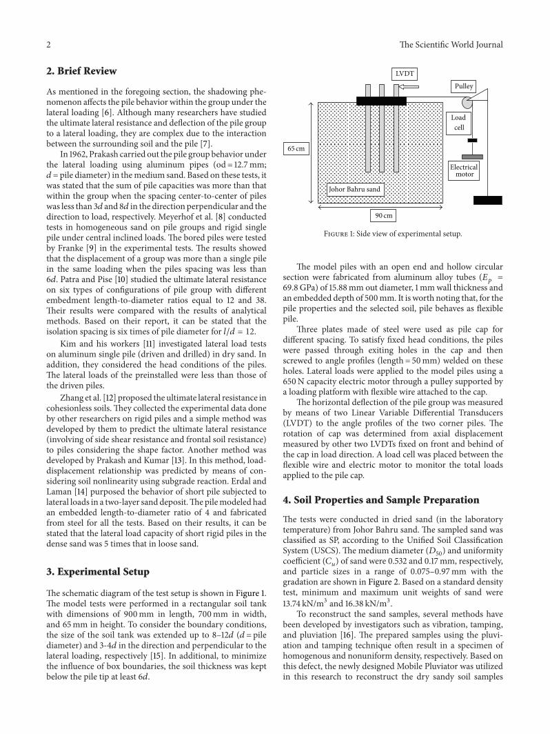
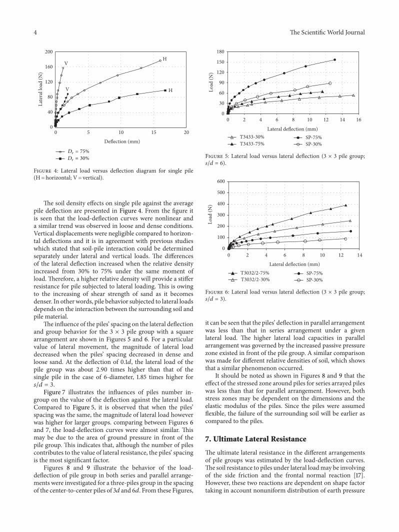
The influence of the piles’ spacing on the lateral deflectionand group behavior for the 3 × 3 pile group with a squarearrangement are shown in Figures 5 and 6. For a particularvalue of lateral movement, the magnitude of lateral loaddecreased when the piles’ spacing decreased in dense andloose sand. At the deflection of 0.1𝑑, the lateral load of thepile group was about 2.90 times higher than that of thesingle pile in the case of 6-diameter, 1.85 times higher for𝑠/𝑑 = 3.
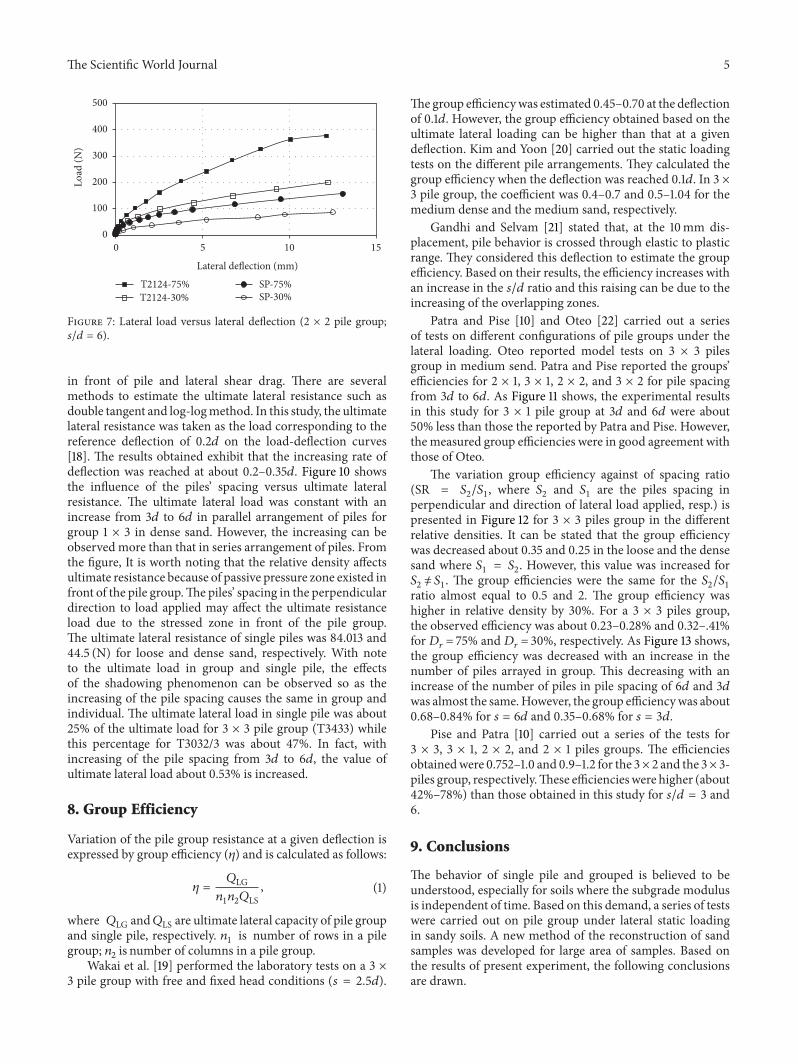
Figure 7 illustrates the influences of piles number in-group on the value of the deflection against the lateral load.Compared to Figure 5, it is observed that when the piles’spacing was the same, the magnitude of lateral load howeverwas higher for larger groups. comparing between Figures 6and 7, the load-deflection curves were almost similar. Thismay be due to the area of ground pressure in front of thepile group. This indicates that, although the number of pilescontributes to the value of lateral resistance, the piles’ spacingis the most significant factor.
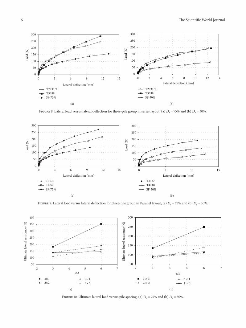
Figures 8 and 9 illustrate the behavior of the load-deflection of pile group in both series and parallel arrange-ments were investigated for a three-piles group in the spacingof the center-to-center piles of 3𝑑 and 6𝑑. From these Figures,
0
30
60
90
120
150
180
0 2 4 6 8 10 12 14 16
Load
(N)
Lateral deflection (mm)T3433-30%T3433-75%
SP-75%SP-30%
Figure 5: Lateral load versus lateral deflection (3 × 3 pile group;𝑠/𝑑 = 6).
0
100
200
300
400
500
600
0 2 4 6 8 10 12 14
Load
(N)
Lateral deflection (mm)T3032/2-75%T3032/2-30%
SP-75%SP-30%
Figure 6: Lateral load versus lateral deflection (3 × 3 pile group;𝑠/𝑑 = 3).
it can be seen that the piles’ deflection in parallel arrangementwas less than that in series arrangement under a givenlateral load. The higher lateral load capacities in parallelarrangement was governed by the increased passive pressurezone existed in front of the pile group. A similar comparisonwas made for different relative densities of soil, which showsthat a similar phenomenon occurred.
It should be noted as shown in Figures 8 and 9 that theeffect of the stressed zone around piles for series arrayed pileswas less than that for parallel arrangement. However, bothstress zones may be dependent on the dimensions and theelastic modulus of the piles. Since the piles were assumedflexible, the failure of the surrounding soil will be earlier ascompared to the piles.
7. Ultimate Lateral Resistance
The ultimate lateral resistance in the different arrangementsof pile groups was estimated by the load-deflection curves.The soil resistance to piles under lateral loadmay be involvingof the side friction and the frontal normal reaction [17].However, these two reactions are dependent on shape factortaking in account nonuniform distribution of earth pressure
The Scientific World Journal 5
0
100
200
300
400
500
0 5 10 15
T2124-75%T2124-30%
SP-75%SP-30%
Load
(N)
Lateral deflection (mm)
Figure 7: Lateral load versus lateral deflection (2 × 2 pile group;𝑠/𝑑 = 6).
in front of pile and lateral shear drag. There are severalmethods to estimate the ultimate lateral resistance such asdouble tangent and log-logmethod. In this study, the ultimatelateral resistance was taken as the load corresponding to thereference deflection of 0.2𝑑 on the load-deflection curves[18]. The results obtained exhibit that the increasing rate ofdeflection was reached at about 0.2–0.35𝑑. Figure 10 showsthe influence of the piles’ spacing versus ultimate lateralresistance. The ultimate lateral load was constant with anincrease from 3𝑑 to 6𝑑 in parallel arrangement of piles forgroup 1 × 3 in dense sand. However, the increasing can beobserved more than that in series arrangement of piles. Fromthe figure, It is worth noting that the relative density affectsultimate resistance because of passive pressure zone existed infront of the pile group.The piles’ spacing in the perpendiculardirection to load applied may affect the ultimate resistanceload due to the stressed zone in front of the pile group.The ultimate lateral resistance of single piles was 84.013 and44.5 (N) for loose and dense sand, respectively. With noteto the ultimate load in group and single pile, the effectsof the shadowing phenomenon can be observed so as theincreasing of the pile spacing causes the same in group andindividual. The ultimate lateral load in single pile was about25% of the ultimate load for 3 × 3 pile group (T3433) whilethis percentage for T3032/3 was about 47%. In fact, withincreasing of the pile spacing from 3𝑑 to 6𝑑, the value ofultimate lateral load about 0.53% is increased.
8. Group Efficiency
Variation of the pile group resistance at a given deflection isexpressed by group efficiency (𝜂) and is calculated as follows:
𝜂 =
𝑄LG𝑛1𝑛2𝑄LS
, (1)
where 𝑄LG and𝑄LS are ultimate lateral capacity of pile groupand single pile, respectively. 𝑛1 is number of rows in a pilegroup; 𝑛2 is number of columns in a pile group.
Wakai et al. [19] performed the laboratory tests on a 3 ×3 pile group with free and fixed head conditions (𝑠 = 2.5𝑑).
The group efficiencywas estimated 0.45–0.70 at the deflectionof 0.1𝑑. However, the group efficiency obtained based on theultimate lateral loading can be higher than that at a givendeflection. Kim and Yoon [20] carried out the static loadingtests on the different pile arrangements. They calculated thegroup efficiency when the deflection was reached 0.1𝑑. In 3 ×3 pile group, the coefficient was 0.4–0.7 and 0.5–1.04 for themedium dense and the medium sand, respectively.
Gandhi and Selvam [21] stated that, at the 10mm dis-placement, pile behavior is crossed through elastic to plasticrange. They considered this deflection to estimate the groupefficiency. Based on their results, the efficiency increases withan increase in the 𝑠/𝑑 ratio and this raising can be due to theincreasing of the overlapping zones.
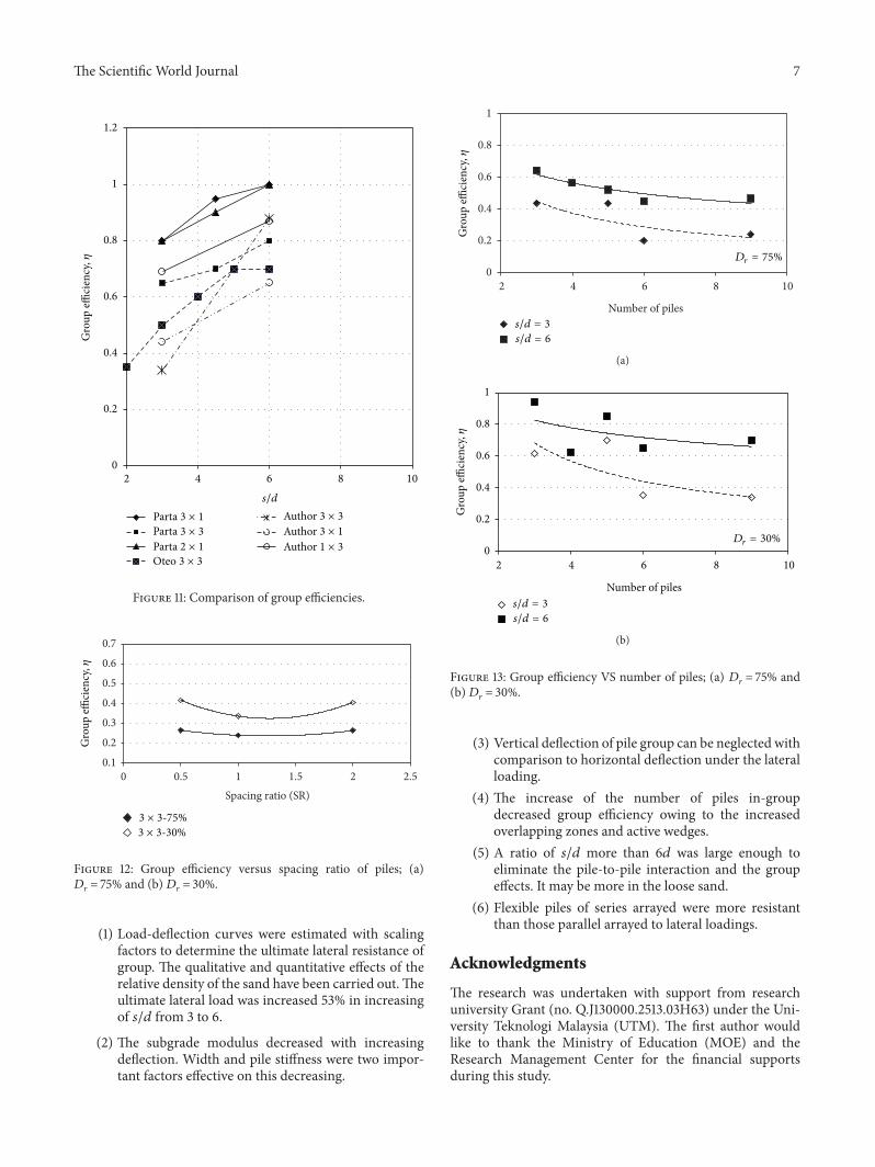
Patra and Pise [10] and Oteo [22] carried out a seriesof tests on different configurations of pile groups under thelateral loading. Oteo reported model tests on 3 × 3 pilesgroup in medium send. Patra and Pise reported the groups’efficiencies for 2 × 1, 3 × 1, 2 × 2, and 3 × 2 for pile spacingfrom 3𝑑 to 6𝑑. As Figure 11 shows, the experimental resultsin this study for 3 × 1 pile group at 3𝑑 and 6𝑑 were about50% less than those the reported by Patra and Pise. However,the measured group efficiencies were in good agreement withthose of Oteo.
The variation group efficiency against of spacing ratio(SR = 𝑆2/𝑆1, where 𝑆2 and 𝑆1 are the piles spacing inperpendicular and direction of lateral load applied, resp.) ispresented in Figure 12 for 3 × 3 piles group in the differentrelative densities. It can be stated that the group efficiencywas decreased about 0.35 and 0.25 in the loose and the densesand where 𝑆1 = 𝑆2. However, this value was increased for𝑆2 ̸= 𝑆1. The group efficiencies were the same for the 𝑆2/𝑆1ratio almost equal to 0.5 and 2. The group efficiency washigher in relative density by 30%. For a 3 × 3 piles group,the observed efficiency was about 0.23–0.28% and 0.32–.41%for 𝐷𝑟 = 75% and 𝐷𝑟 = 30%, respectively. As Figure 13 shows,the group efficiency was decreased with an increase in thenumber of piles arrayed in group. This decreasing with anincrease of the number of piles in pile spacing of 6𝑑 and 3𝑑was almost the same.However, the group efficiencywas about0.68–0.84% for 𝑠 = 6𝑑 and 0.35–0.68% for 𝑠 = 3𝑑.
Pise and Patra [10] carried out a series of the tests for3 × 3, 3 × 1, 2 × 2, and 2 × 1 piles groups. The efficienciesobtainedwere 0.752–1.0 and 0.9–1.2 for the 3× 2 and the 3× 3-piles group, respectively.These efficiencieswere higher (about42%–78%) than those obtained in this study for 𝑠/𝑑 = 3 and6.
9. Conclusions
The behavior of single pile and grouped is believed to beunderstood, especially for soils where the subgrade modulusis independent of time. Based on this demand, a series of testswere carried out on pile group under lateral static loadingin sandy soils. A new method of the reconstruction of sandsamples was developed for large area of samples. Based onthe results of present experiment, the following conclusionsare drawn.
6 The Scientific World Journal
0
50
100
150
200
250
300
0 3 6 9 12 15
T2931/2T3638SP-75%
Load
(N)
Lateral deflection (mm)
(a)
0
50
100
150
200
250
300
0 2 4 6 8 10 12 14
T2931/2T3638SP-30%
Load
(N)
Lateral deflection (mm)
(b)
Figure 8: Lateral load versus lateral deflection for three-pile group in series layout; (a)𝐷𝑟 = 75% and (b)𝐷𝑟 = 30%.
0
50
100
150
200
250
300
0 3 6 9 12 15
T3537T4240SP-75%
Load
(N)
Lateral deflection (mm)
(a)
0
50
100
150
200
250
300
0 5 10 15
T3537T4240SP-30%
Load
(N)
Lateral deflection (mm)
(b)
Figure 9: Lateral load versus lateral deflection for three-pile group in Parallel layout; (a)𝐷𝑟 = 75% and (b)𝐷𝑟 = 30%.
50
100
150
200
250
300
350
400
2 3 4 5 6 7
Ulti
mat
e lat
eral
resis
tanc
e (N
)
s/d
3×32×2
3×1
1×3
(a)
50
100
150
200
250
300
2 3 4 5 6 7
Ulti
mat
e lat
eral
resis
tanc
e (N
)
s/d
3 × 3
2 × 2 1 × 3
3 × 1
(b)
Figure 10: Ultimate lateral load versus pile spacing; (a) 𝐷𝑟 = 75% and (b)𝐷𝑟 = 30%.
The Scientific World Journal 7
0
0.2
0.4
0.6
0.8
1
1.2
2 4 6 8 10
Gro
up effi
cien
cy,𝜂
s/d
PartaPartaPartaOteo
AuthorAuthorAuthor
3 × 3
3 × 1
3 × 1
1 × 32 × 1
3 × 3
3 × 3
Figure 11: Comparison of group efficiencies.
0.1
0.2
0.3
0.4
0.5
0.6
0.7
0 0.5 1 1.5 2 2.5Spacing ratio (SR)
Gro
up effi
cien
cy,𝜂
3 × 3-75%3 × 3-30%
Figure 12: Group efficiency versus spacing ratio of piles; (a)𝐷𝑟 = 75% and (b)𝐷𝑟 = 30%.
(1) Load-deflection curves were estimated with scalingfactors to determine the ultimate lateral resistance ofgroup. The qualitative and quantitative effects of therelative density of the sand have been carried out.Theultimate lateral load was increased 53% in increasingof 𝑠/𝑑 from 3 to 6.
(2) The subgrade modulus decreased with increasingdeflection. Width and pile stiffness were two impor-tant factors effective on this decreasing.
0
0.2
0.4
0.6
0.8
1
2 4 6 8 10
Number of piles
Gro
up effi
cien
cy,𝜂
s/d = 3
s/d = 6
Dr = 75%
(a)
0
0.2
0.4
0.6
0.8
1
2 4 6 8 10
Number of piles
Gro
up effi
cien
cy,𝜂
Dr = 30%
s/d = 3
s/d = 6
(b)
Figure 13: Group efficiency VS number of piles; (a) 𝐷𝑟 = 75% and(b)𝐷𝑟 = 30%.
(3) Vertical deflection of pile group can be neglected withcomparison to horizontal deflection under the lateralloading.
(4) The increase of the number of piles in-groupdecreased group efficiency owing to the increasedoverlapping zones and active wedges.
(5) A ratio of 𝑠/𝑑 more than 6𝑑 was large enough toeliminate the pile-to-pile interaction and the groupeffects. It may be more in the loose sand.
(6) Flexible piles of series arrayed were more resistantthan those parallel arrayed to lateral loadings.
Acknowledgments
The research was undertaken with support from researchuniversity Grant (no. Q.J130000.2513.03H63) under the Uni-versity Teknologi Malaysia (UTM). The first author wouldlike to thank the Ministry of Education (MOE) and theResearch Management Center for the financial supportsduring this study.
8 The Scientific World Journal
References
[1] M. Khari, A. K. Kassim, and A. Adnan, “Kinematic bendingmoment of piles under seismic motions,”Asian Journal of EarthSciences. In press.
[2] M.H. El Naggar,M. A. Shayanfar,M. Kimiaei, andA. A. Aghak-ouchak, “Simplified BNWF model for nonlinear seismic re-sponse analysis of offshore piles with nonlinear input groundmotion analysis,” Canadian Geotechnical Journal, vol. 42, no. 2,pp. 365–380, 2005.
[3] M. Khari, A. K. Kassim, and A. Adnan, “Dynamic soil-pileinteraction under earthquake events,” in Proceedings of theAICCE/GIZ’12, Park Royal Penang Resort, Penang, Malaysia,2012.
[4] M. Khari, A. K. Kassim, and A. Adnan, “Effects of soil modelon site response analyses,” Asian Journal of Scientific Research.In press.
[5] M. Khari, A. K. Kassim, and A. Adnan, “Development of p-ycurves of laterally loaded piles in cohesionless soil,” ScientificWorld Journal. In press.
[6] D. Brown, C. Morrison, and L. Reese, “Lateral load behavior ofa pile group in sand,” Geotechnical and Geological Engineering,vol. 114, pp. 1261–1276, 1988.
[7] M. Khari, A. K. Kassim, and A. Adnan, “The effects of soil-pileinteraction on seismic parameters of superstructure,” in Pro-ceedings of the 2nd International Conference on Geotechnique,Construction Materials and Environment (GEOMAT ’12), pp.479–484, Kuala Lumpur, Malaysia, November 2012.
[8] G. G. Meyerhof, A. S. Yalcin, and S. K. Mathur, “Ultimate pilecapacity for eccentric inclined load,” Journal of GeotechnicalEngineering, vol. 109, no. 3, pp. 408–423, 1983.
[9] E. Franke, “Group action between vertical piles under horizon-tal loads,” in Deep Foundations on Bored and Auger Piles, W. F.V. Impe, Ed., Balkema, Rotterdam, The Netherlands, 1988.
[10] N. R. Patra and P. J. Pise, “Ultimate lateral resistance of pilegroups in sand,” Journal of Geotechnical and GeoenvironmentalEngineering, vol. 127, no. 6, pp. 481–487, 2001.
[11] B. T. Kim, N.-K. Kim, W. J. Lee, and Y. S. Kim, “Experimentalload-transfer curves of laterally loaded piles in Nak-DongRiver sand,” Journal of Geotechnical and GeoenvironmentalEngineering, vol. 130, no. 4, pp. 416–425, 2004.
[12] J. Zhang, R. D. Andrus, and C. H. Juang, “Normalized shearmodulus and material damping ratio relationships,” Journal ofGeotechnical and Geoenvironmental Engineering, vol. 131, no. 4,pp. 453–464, 2005.
[13] S. Prakash and S. Kumar, “Nonlinear lateral pile deflection pre-diction in sands,” Journal of Geotechnical and GeoenvironmentalEngineering, vol. 122, no. 2, pp. 130–138, 1996.
[14] U. Erdal and M. Laman, “Lateral resistance of a short rigid pilein a two-layer cohesionless soil,” Acta Geotechnica Slovenia, vol.2, pp. 19–43, 2011.
[15] S. Narasimha Rao, V. G. S. T. Ramakrishna, and M. BabuRao, “Influence of rigidity on laterally loaded pile groups inmarine clay,” Journal of Geotechnical and GeoenvironmentalEngineering, vol. 124, no. 6, pp. 542–549, 1998.
[16] M. Khari, A. K. Kassim, and A. Adnan, “Snad sample prepara-tion usingmobilepluviator,”TheArabian Journal for Science andEngineering. In press.
[17] T. D. Smith, “Pile horizontal soil modulus values,” Journal ofGeotechnical Engineering, vol. 113, no. 9, pp. 1040–1044, 1987.
[18] B. Broms, “Lateral resistance of piles in cohesive soils,” SoilMechanics and Foundations Division, vol. 90, pp. 27–63, 1964.
[19] A.Wakai, S.Gose, andK.Ugai, “3-D elasto-plastic finite elementanalyses of pile foundations subjected to lateral loading,” Soilsand Foundations, vol. 39, no. 1, pp. 97–111, 1999.
[20] B. T. Kim and G. L. Yoon, “Laboratory modeling of laterallyloaded pile groups in sand,” Civil Engineering, vol. 15, pp. 65–75, 2011.
[21] S. R. Gandhi and S. Selvam, “Group effect on driven piles underlateral load,” Journal of Geotechnical and GeoenvironmentalEngineering, vol. 123, no. 8, pp. 702–709, 1997.
[22] C. S. Oteo, “Displacements of vertical pile group subjected tolateral loads,” in Proceedings of the 5th European Conferenceon Soil Mechanics and Foundation Engineering, pp. 397–405,Madrid, Spain, 1972.

International Journal of
AerospaceEngineeringHindawi Publishing Corporationhttp://www.hindawi.com Volume 2014
RoboticsJournal of
Hindawi Publishing Corporationhttp://www.hindawi.com Volume 2014
Hindawi Publishing Corporationhttp://www.hindawi.com Volume 2014
Active and Passive Electronic Components
Control Scienceand Engineering
Journal of
Hindawi Publishing Corporationhttp://www.hindawi.com Volume 2014
International Journal of
RotatingMachinery
Hindawi Publishing Corporationhttp://www.hindawi.com Volume 2014
Hindawi Publishing Corporation http://www.hindawi.com
Journal ofEngineeringVolume 2014
Submit your manuscripts athttp://www.hindawi.com
VLSI Design
Hindawi Publishing Corporationhttp://www.hindawi.com Volume 2014
Hindawi Publishing Corporationhttp://www.hindawi.com Volume 2014
Shock and Vibration
Hindawi Publishing Corporationhttp://www.hindawi.com Volume 2014
Civil EngineeringAdvances in
Acoustics and VibrationAdvances in
Hindawi Publishing Corporationhttp://www.hindawi.com Volume 2014
Hindawi Publishing Corporationhttp://www.hindawi.com Volume 2014
Electrical and Computer Engineering
Journal of
Advances inOptoElectronics
Hindawi Publishing Corporation http://www.hindawi.com
Volume 2014
The Scientific World JournalHindawi Publishing Corporation http://www.hindawi.com Volume 2014
SensorsJournal of
Hindawi Publishing Corporationhttp://www.hindawi.com Volume 2014
Modelling & Simulation in EngineeringHindawi Publishing Corporation http://www.hindawi.com Volume 2014
Hindawi Publishing Corporationhttp://www.hindawi.com Volume 2014
Chemical EngineeringInternational Journal of Antennas and
Propagation
International Journal of
Hindawi Publishing Corporationhttp://www.hindawi.com Volume 2014
Hindawi Publishing Corporationhttp://www.hindawi.com Volume 2014
Navigation and Observation
International Journal of
Hindawi Publishing Corporationhttp://www.hindawi.com Volume 2014
DistributedSensor Networks
International Journal of