
Research Article A Fully Reconfigurable Polarimetric ...
15
Research Article A Fully Reconfigurable Polarimetric Phased Array Antenna Testbed Sudantha Perera, 1 Yu Pan, 1 Yan Zhang, 1 Xining Yu, 1 Dusan Zrnic, 2 and Richard Doviak 2 1 Advanced Radar Research Center (ARRC) and Department of Electrical and Computer Engineering, University of Oklahoma, Norman, OK, USA 2 National Severe Storms Laboratory (NSSL), National Oceanic and Atmospheric Administration (NOAA), Norman, OK, USA Correspondence should be addressed to Yan Zhang; [email protected] Received 7 January 2014; Accepted 26 May 2014; Published 6 August 2014 Academic Editor: Stefano Selleri Copyright © 2014 Sudantha Perera et al. is is an open access article distributed under the Creative Commons Attribution License, which permits unrestricted use, distribution, and reproduction in any medium, provided the original work is properly cited. e configurable phased array demonstrator (CPAD) is a low-cost, reconfigurable, small-scale testbed for the dual-polarized array antenna and radar prototype. It is based on the concept that individual transmit and receive (TR) modules and radiating elements can be configured in different ways to study the impact of various array manifolds on radiation pattern performance. For example, CPAD is configured as (a) a 4 × 4 planar array, (b) a planar array with mirror configuration, and (c) a circular array to support the multifunctional phased array radar (MPAR) system risk reduction studies. System descriptions are given in detail, and measurements are made and results are analyzed. 1. Introduction Risk mitigation of a large-scale, multifunctional phased array radar (MPAR) usually involves [1] designing, fabricating, and testing small-scale subarray panels and [2] scaling up to larger array systems. Oſten these subarrays are based on assump- tions about the linear or planar array manifold. However, there have been other options for the array manifold, such as the cylindrical array [3] and the sparse array [4]. Although theoretical analysis has claimed unique advantages for each of the different array manifold options, testing the different design options with full-scale systems built for each option is expensive and time consuming. A laboratory scale testbed that can be instrumented for fair, quantitative, and precise design comparisons is needed. Because the main focus of our investigation is how the array manifold configurations affect the polarimetric array radiation pattern, a configurable phased array demonstrator (CPAD) is developed based on integrating the radiating ele- ment with the individual T/R module. e array manifold, as well as the beamforming and control circuitry, can be rapidly reconfigured (Figure 1), as in the case of the planar subarray (Figure 2(a)) and the circular/conformal array (Figure 2(b)). Multiple circular structures can be stacked together to analyze the performance of manifolds on scalable and complicated curvature surfaces. It is shown that a simple measurement procedure can be developed, and accurate measurement data for the scalable validation of candidate array antenna system designs can be provided with this concept. is paper is organized as follows. In Sections 2 and 3, basic system architecture and CPAD TR module designs are discussed. Section 4 introduces CPAD configuration for both planar and circular arrays. Sections 5 and 6 describe the measurement method and procedures, as well as detailed measurement results. Discussion and conclusions are found in Section 7. 2. Instrumentation Components 2.1. Front End. e individual TR modules of the CPAD have independent antennas and control signals so that they can easily fit into different manifold structures. Various antenna element designs can be attached to the TR modules as long as they are within the maximal allowable dimensions (3 ×3 for the current configuration). With this architecture, the Hindawi Publishing Corporation International Journal of Antennas and Propagation Volume 2014, Article ID 439606, 14 pages http://dx.doi.org/10.1155/2014/439606
Transcript of Research Article A Fully Reconfigurable Polarimetric ...

Research ArticleA Fully Reconfigurable Polarimetric PhasedArray Antenna Testbed
Sudantha Perera1 Yu Pan1 Yan Zhang1 Xining Yu1 Dusan Zrnic2 and Richard Doviak2
1 Advanced Radar Research Center (ARRC) and Department of Electrical and Computer Engineering University of OklahomaNorman OK USA
2National Severe Storms Laboratory (NSSL) National Oceanic and Atmospheric Administration (NOAA) Norman OK USA
Correspondence should be addressed to Yan Zhang rockeeouedu
Received 7 January 2014 Accepted 26 May 2014 Published 6 August 2014
Academic Editor Stefano Selleri
Copyright copy 2014 Sudantha Perera et alThis is an open access article distributed under theCreativeCommonsAttribution Licensewhich permits unrestricted use distribution and reproduction in any medium provided the original work is properly cited
The configurable phased array demonstrator (CPAD) is a low-cost reconfigurable small-scale testbed for the dual-polarizedarray antenna and radar prototype It is based on the concept that individual transmit and receive (TR) modules and radiatingelements can be configured in different ways to study the impact of various array manifolds on radiation pattern performance Forexample CPAD is configured as (a) a 4 times 4 planar array (b) a planar array with mirror configuration and (c) a circular array tosupport the multifunctional phased array radar (MPAR) system risk reduction studies System descriptions are given in detail andmeasurements are made and results are analyzed
1 Introduction
Risk mitigation of a large-scale multifunctional phased arrayradar (MPAR) usually involves [1] designing fabricating andtesting small-scale subarray panels and [2] scaling up to largerarray systems Often these subarrays are based on assump-tions about the linear or planar array manifold Howeverthere have been other options for the array manifold suchas the cylindrical array [3] and the sparse array [4] Althoughtheoretical analysis has claimed unique advantages for eachof the different array manifold options testing the differentdesign options with full-scale systems built for each optionis expensive and time consuming A laboratory scale testbedthat can be instrumented for fair quantitative and precisedesign comparisons is needed
Because the main focus of our investigation is how thearray manifold configurations affect the polarimetric arrayradiation pattern a configurable phased array demonstrator(CPAD) is developed based on integrating the radiating ele-ment with the individual TR moduleThe array manifold aswell as the beamforming and control circuitry can be rapidlyreconfigured (Figure 1) as in the case of the planar subarray(Figure 2(a)) and the circularconformal array (Figure 2(b))
Multiple circular structures can be stacked together to analyzethe performance of manifolds on scalable and complicatedcurvature surfaces It is shown that a simple measurementprocedure can be developed and accurate measurement datafor the scalable validation of candidate array antenna systemdesigns can be provided with this concept
This paper is organized as follows In Sections 2 and3 basic system architecture and CPAD TR module designsare discussed Section 4 introduces CPAD configuration forboth planar and circular arrays Sections 5 and 6 describethe measurement method and procedures as well as detailedmeasurement results Discussion and conclusions are foundin Section 7
2 Instrumentation Components
21 Front End The individual TRmodules of the CPAD haveindependent antennas and control signals so that they caneasily fit into different manifold structures Various antennaelement designs can be attached to the TRmodules as long asthey are within the maximal allowable dimensions (310158401015840 times 310158401015840for the current configuration) With this architecture the
Hindawi Publishing CorporationInternational Journal of Antennas and PropagationVolume 2014 Article ID 439606 14 pageshttpdxdoiorg1011552014439606
2 International Journal of Antennas and Propagation
Backend controllers
Reconfigurable array manifolds
∙ TRM with radiating elements
Figure 1 The CPAD concept
(a) An example of a polarimetric planar array config-uration
(b) An example of a polarimetric circular array con-figuration
Figure 2 3D model of example CPAD configurations
CPADcan function as a subarray in a large-scale array systemor it can be reconfigured to study the performance of differentarray manifold designs for the risk mitigation missionsincluding the cost and performance of large systems Aninitial demonstration of the CPAD is developed with 16radiating elements (4 times 4) which are separated by 07120582spacingThe operating frequency is 2705GHzThe front-endcircuitry is shown in Figure 3
22 TR Modules An introduction of the development of theTR module was presented earlier in [5] The structure of theCPAD TR module is depicted in Figure 3 The CPAD TRmodules are designed to have all the required circuit elementsin a typical modern phased array radar with self-containedfeatures that is the individual antenna elements are attacheddirectly to the TR modules and the microcontroller unit(MCU) in each TR module can store its own program tocontrol the phase shift and attenuation of each polarimetricchannel At the same time a master MCU board can com-municate with the MCUs within all the TR modules througha serial peripheral interface (SPI) for program loading syn-chronizing and so forth TR modules have the same external
global triggeringcontrol signal which can have a 5 dutycycle without overloading the high power amplifier (HPA)This triggering signal is used to control the TR switcheswhich enable sharing the same phased shifter (PS) and atten-uator (ATT) for both transmission and reception signals asin Figure 3 The amplifiers in TRMs (LNA preamplifier andHPA) can operate in both continuous wave (CW) and pulsedmodes In laboratory measurements low-power continuoustransmission is more appropriate because it avoids possibleelectromagnetic hazards for equipment and people and it issimpler to implement For field demonstrations the higherpower pulsed mode is necessary since high peak power isimportant for effective range performance When operatingin pulse mode the amplifiers in all the TR modules aresynchronized with the same triggering signal
Each TR module consists of LNA preamp HPA phaseshifter attenuator and polarized microstrip patch radiatingelements The power dividersplitters in the CPAD are com-mon components of the beamformer for both transmissionand reception The same architecture is used for both hori-zontal and vertical polarizations Images of individual TRMsare shown in Figure 4 Each TR module contains four PCB
International Journal of Antennas and Propagation 3
V(0)
V(15)
0123456789
101112131415
SW
SW
TRSW
Preamp HPA
SW
Limiter
LNA
H(0)PS
ATT
SW
SWPreamp HPA
SW
Limiter
LNA
H(15)PS
ATT
H
V
Pow
er co
mbi
ner
pow
er sp
litte
rTR
TRTR
TR
TR
TRSWTR
Figure 3 An example of CPAD front-end system architecture for planar array demo
boards as well as the microstrip patch antenna As shownin Figure 4(a) the RF transceiver and controller board havebeen assembled with TR switches a phased shifter LNAattenuator and limiter The MCU board is attached to theback of the RF transceiver and controller board For the highpower version the power amplifier boards for the H and Vchannels are identical Figure 4(c) shows a GaN HPA boardfor one channel For low-power HPA only the preamplifiersare used and the two channels are integrated on the sameboard All the TRMs are carefully tested to ensure theiroperational stability before installing them into the arraysystem
3 CPAD Integration
31 Planar Array An initial demonstration of the CPADis via a simple planar subarray system which is shown inFigure 5(a) 16 TR modules are mounted on the 30 cm times30 cm aluminum plate of the CPAD structure to constructa 4 times 4 polarimetric antenna array In this demonstrationthe radiation elements can be either arranged normally (allin the same orientation) or in a mirror configuration [6] (theorientation in Figure 12) if cross-polarization levels need to
be suppressed at broadsideThe arraymanifold in Figure 5(a)also shows three layers of electronics (1) the power dividercombiner and cabling (2) the TR module and antennas and(3) the master MCU for the subarray and power suppliers(110 V AC to 28V DC converters) which are mounted onthe third plate At the subarray level the master MCU cancommunicate with a computer through a USB port andtransfer the phaseattenuation codes of all the TRMs
A LabVIEW program runs on the computer with asimple graphic user interface (GUI) The antenna elementsare divided into three regions labeled as 1 2 and 3 ona 4 times 4 array (Table 1) The first region has four elementsnear the center The second region has elements at the fourcorners The third region has the remaining eight elementsBy adjusting the relative power to elements in each of theregions we can optimize the amplitude tapering The userinterface accepts specified phase shifts and attenuations tosteer and form the beam
32 Circular Array The circular array (or ring array) hasmany applications in communication radar and directionalfinding systems [7] It is also an important candidate forthe polarimetric MPAR manifold [2] The CPAD has been
4 International Journal of Antennas and Propagation
SW SW HPA Block Limiter
Attenuator Phase shifter LNA Power SW
(a) A close look of V channel RF circuit (b) A completed TRmodule with RF boardtwo 40 dBm HPAsRf board and a dual-polarized patch antenna
(c) The GaN HPAboard NPT25015 tran-sistor from NITRONEXis used
Figure 4 TR module
(a) Planar subarray manifold to study the polarimetric arraypattern variation with different scanning angles (1) is thebeamformer (2) is the RF board and (3) is power supply
(b) 4-element circular array mani-fold to study the polarimetric arraypattern variation with different scan-ning angles
Figure 5 The CPAD being integrated
Table 1 Three regions of the antenna elements distribution on the4 times 4 array
Region Element labels (refer to Figure 8) Attenuation1 (1 1) (1 2) (2 1) and (2 2) 0 dB2 (0 0) (0 3) (3 0) and (3 3) 15 dB
3 (0 1) (0 2) (1 0) (2 0) and (3 1) 5 dB(3 2) (1 3) and (2 3)
configured as a 16-element circular array for the initial con-formal array demonstration During pattern measurementsthe CPAD was configured as either a 4-element (depictedin Figure 5(b)) or an 8-element circular array Integration of
the circular array is identical to the planar CPAD except forthe antenna manifold on top of the RF system
4 Measurement Method
The initial measurements of the planar CPAD were made inan anechoic chamber at the University of Oklahoma usinga vector network analyzer (VNA) (Agilent E8364B PNAnetwork analyzer is used) The tests performed were for thereceive-mode array and the low power transmit-mode array(the HPAs were not activated)
Antenna measurement setup is shown in Figure 6 TheCPAD test antenna array was mounted on a positioningsystem consisting of an azimuth rotary stage (soloist single-axis digital servo controller is used to control the azimuth
International Journal of Antennas and Propagation 5
CPAD
Source antenna
Rotary stage
Control and data signal
Agilent PNA network analyzer
Coaxial cable
Coaxial cable
USBRotary stage
controller
120601
Figure 6 Block diagram of H-H H-V V-V or V-H pattern measurements
(a) Planar array (b) Circular array
Figure 7 The CPAD is mounted on the rotary stage for antenna positioning
(AZ) angle of the positioning system) as shown in Figures7(a) and 7(b) The dual-polarized KOUN (KOUN is aprototype dual-pol WSR-88D radar system) feed-horn wasused as the source antenna which was connected to thetransmitting signal generating port of the PNAThe transmitpower was 9 dBm The PNA collects via the coaxial cablethe received signals from the antenna array it controls thepositioning system simultaneously The network analyzeris programmed to collect 200 samples of received signalsbetween 2700MHz and 2710MHz The software invokes ascript to increment a one-degree angle in AZ each time thescript is executed Then the VNA software collects the datafrom the test antenna and saves the data as a text file witha unique name This simple setup can collect measurements
over a 180-degree azimuth angle range for the CPAD withone-degree resolution Measurements with antenna taperingare done by changing the attenuation of regions 2 and 3of the antenna elements listed in Table 1 while maintainingzero attenuation in the elements of Region 1 The optimalamplitude tapering for achieving a minimum sidelobe levelfor the 4 times 4 array was computed using the particle swarmoptimization method [8 9] and the attenuation factors usedin the measurements are shown in Figure 8
5 Planar Array Radiation Patterns
The pattern function can be derived using Fourier seriesmethods as in [10]
6 International Journal of Antennas and Propagation
(0 0) (0 1) (0 2) (0 3)
(1 3)(1 2)(1 1)(1 0)
(2 0) (2 1) (2 2) (2 3)
(3 3)(3 2)(3 1)(3 0)
15dB 15dB5dB5dB
5dB
5dB
5dB 5dB
0dB 0dB
0dB 0dB 5dB
5dB
15dB15dB
76
mm
76mm
Figure 8 Attenuation map for each element for optimum tapering in theory
51 Receive Array Beam Steering without Amplitude TaperingFigure 9 presents the measurement results of polarimetricplanar antenna array patterns for different azimuth scan-ning angles No amplitude tapering was applied Measuredcopolarization (Co) and cross-polarization (X) patterns arebased on vertical (V) or horizontal (H) polarizations ofthe sourcetransmit horn (according to the nature of themeasurement method definition 3 of cross-polarization [11]is used) The simulated co- and cross-polarization patternsare based on an open-source finite-difference time-domain(FDTD) EM solver [12] A good agreement between themeasurement and simulation radiation patterns of the copo-larization and the power level of the cross-polarizationpatterns are observed for most of the steering angles
Note that as the array scans electronically the cross-polarization pattern also varies and a cross-polarization peakappears in a similar direction as the main beam steers off-broadside At broadside the full-wave simulation pattern hasa deep null while the measurement pattern results generallydo not show this null This is mainly due to the KOUNhorn itself having a peak (about minus35 dB) in the cross-polarization pattern Considering that the antennas used inthis configuration were simple probe-fed patched antennasthese initial results help general studies of planar array cross-polarization pattern evolution with different steering angleswhile the power level of the cross-polarization pattern maybe further suppressed if the radiating elements are replacedby more sophisticated designs
52 Receive Array Beam Steering with Optimal AmplitudeTapering Amplitude tapering is a common technology to
reduce the array pattern sidelobes (eg to below minus20 dBin this experiment) at the cost of a broader beamwidthAs mentioned in Section 4 Figure 8 an amplitude taperingtechnique based on a nonlinear optimization procedure wasused in the demonstrative experiment The measurementresults and comparison with the simulations are again shownin Figure 10 Minor adjustments to the tapering factors wereapplied to the theoretical values during the measurements(Figure 11) to take account of the attenuator quantizationeffects In the measurement results shown in Figure 10the copolarized V and cross-polarized H patterns match thesimulation results very well The H copolarized pattern hasnoticeable distortion at small positive steering angles whichis possibly due to some interference by the H polarizationwithin the chamber setup
53 Transmit Array Mirror Configuration for Reducing Cross-Polarization Levels The mirror array configuration [13] hasbeen introduced in previous studies as a possible methodfor reducing cross-polarization levels The CPAD enablesresearchers to configure the planar array with a differentmirror manifold and different numbers of antenna elementsThe pattern of mirror configuration is easy to obtain withtransmit arrays Figure 12 shows a simple 2 times 2 mirrorconfiguration as an example A comparison of the measuredtransmit array pattern for the mirror and nonmirror con-figurations is illustrated in Figure 13 As is seen the mirrorconfiguration indeed reduces the cross-polarization powerlevelsThemost significant improvement however is aroundbroadside Measurements are also performed for the mirrorconfiguration and array beam steering to off-broadside and
International Journal of Antennas and Propagation 7
Nor
mal
ized
pow
er (d
B)
minus80 minus60 minus40 minus20 0 20 40 60 80
0
minus10
minus20
minus30
minus40
minus50
minus60
120579 (deg)
(a) 120601 = 0∘
Nor
mal
ized
pow
er (d
B)
minus80 minus60 minus40 minus20 0 20 40 60 80
0
minus10
minus20
minus30
minus40
minus50
minus60
120579 (deg)
(b) 120601 = 10∘
Nor
mal
ized
pow
er (d
B)
minus80 minus60 minus40 minus20 0 20 40 60 80
0
minus10
minus20
minus30
minus40
minus50
minus60
Measured Co (V)Measured X (V)Measured Co (H)
Measured X (H)Simulated CoSimulated X
120579 (deg)
(c) 120601 = 20∘
Nor
mal
ized
pow
er (d
B)
0
minus10
minus20
minus30
minus40
minus50
minus60minus80 minus60 minus40 minus20 0 20 40 60 80
Measured Co (V)Measured X (V)Measured Co (H)
Measured X (H)Simulated CoSimulated X
120579 (deg)
(d) 120601 = 30∘
Figure 9Measured polarimetric 4times 4 planar array patterns and comparisonwith simulations Beam-steering angle 120601 is in azimuth directionSimulations are performed using FDTD
here the cross-polarization isolation performance degradesquickly which indicates that a mirror configuration designedfor broadside cross-polarization cancellation may not beappropriate for off-broadside arrays
54 Transmit Array 3D Amplitude and Phase Patterns Thetransmit radiation pattern of the CPAD can be characterizedusing near-field measurement techniques (the low-cost near-field measurement tool EMSCAN was used for the mea-surements) Figure 14 depicts the 3D amplitude and phasepattern measurement results The basic profiles of thesepatterns match the corresponding simulation results The 3D
pattern (including phase) characterization is an importantstep in obtaining complete knowledge about polarimetricarray radiations and how to achieve good calibrations It isshown that the CPAD enables such measurements
6 Circular Array Radiation Patterns
In this study we provided electronic beam steering resultsfor a circular array mainly to demonstrate the capability ofthe testbed and to investigate the fundamental properties ofa conformal array manifold and currently not to comparepatterns using electronic beam steering of the planar array
8 International Journal of Antennas and Propagation
Nor
mal
ized
pow
er (d
B)
minus80 minus60 minus40 minus20 0 20 40 60 80
0
minus10
minus20
minus30
minus40
50
minus60
120579 (deg)
(a) 120601 = 0∘
Nor
mal
ized
pow
er (d
B)
minus80 minus60 minus40 minus20 0 20 40 60 80
0
minus10
minus20
minus30
minus40
minus60
minus50
120579 (deg)
(b) 120601 = 5∘
Nor
mal
ized
pow
er (d
B)
minus80 minus60 minus40 minus20 0 20 40 60 80
0
minus10
minus20
minus30
minus40
minus50
minus60
120579 (deg)
(c) 120601 = 10∘
Nor
mal
ized
pow
er (d
B)
minus80 minus60 minus40 minus20 0 20 40 60 80
0
minus10
minus20
minus30
minus40
minus50
minus60
120579 (deg)
(d) 120601 = 15∘
Nor
mal
ized
pow
er (d
B)
0
minus10
minus20
minus30
minus40
minus50
minus60minus80 minus60 minus40 minus20 0 20 40 60 80
Measured Co (V)Measured X (V)Measured Co (H)
Measured X (H)Simulated CoSimulated X
120579 (deg)
(e) 120601 = 20∘
Figure 10 Measured polarimetric array patterns with actual amplitude tapering Beam-steering angle 120601 is in azimuth direction Simulationsare performed using FDTD
International Journal of Antennas and Propagation 9
01887 01887
0188701887
0551 0551
05510551
0551 0551
0551 0551
11
11
(a) Theoretical
0562
0562 0562
0562
0562
05620562
0562
01778
1 1
1 1
0177801778
01778
(b) Actual
Figure 11 Theoretical and actual amplitude tapering values (linear scale values are displayed here in order to compare the configurations)
H∙+V∙+
H∙minus
+ V∙
H∙minus
+ V∙
H∙+V∙+
Figure 12 A simple 2 times 2 mirror array configuration of the CPAD
Co-pol nonmirrorX-pol nonmirror
Co-pol mirrorX-pol mirror
minus80 minus60 minus40 minus20 0 20 40 60 80
Angle (∘)
0
minus5
minus10
minus15
minus20
minus25
minus30
minus35
minus40
minus45
Nor
mal
ized
pow
er (d
B)
2 times 2 V-port fed elevation
(a) Vertical polarization pattern
minus80 minus60 minus40 minus20 0 20 40 60 80
Angle (∘)
Co-pol nonmirrorX-pol nonmirror
Co-pol mirrorX-pol mirror
0
minus5
minus10
minus15
minus20
minus25
minus30
minus35
minus40
minus45
Nor
mal
ized
pow
er (d
B)
2 times 2 H-port fed elevation
(b) Horizontal polarization pattern
Figure 13 Measured radiation patterns for the 2 times 2 arrays
10 International Journal of Antennas and Propagation
minus1 minus05 0
0
05 1
minus5
minus10
minus15
minus20
minus25
minus30
minus35
minus40
1
08
06
04
02
0
minus02
minus04
minus06
minus08
minus1
X = sin(120579)cos(120601)
y=
sin(120579)s
in(120601)
Amplitude of Ecombined (dB)
(a) |119864120579+ 119864120601|
1
1
08
08
06
06
04
04
02
02
0
0
minus02
minus02
minus04
minus04
minus06
minus06
minus08
minus08minus1minus1
y=
sin(120579)s
in(120601)
minus10
minus20
minus30
minus40
minus50
minus60
minus70
X = sin(120579)cos(120601)
Amplitude of E120579 (dB)
(b) |119864120579|
minus1minus1
minus05
minus05
0
0
05
05
1
1
minus10
minus20
minus30
minus40
minus50
minus60
X = sin(120579)cos(120601)
y=
sin(120579)s
in(120601)
Amplitude of E120601 (dB)
(c) |119864120601|
1
08
06
04
02
0
minus02
minus04
minus06
minus08
minus1
y=
sinsin
(120579)
(120601)
1080604020minus02minus04minus06minus08minus1
X = sin(120579)cos(120601)
150
100
50
0
minus50
minus100
minus150
Phase of E120579 (deg)
(d) ang119864120579
1
08
06
04
02
0
minus02
minus04
minus06
minus08
minus1minus1
y=
sinsin
(120579)
(120601)
1080604020minus02minus04minus06minus08
X = sin(120579)cos(120601)
150
100
50
0
minus50
minus100
minus150
Phase of E120601 (deg)
(e) ang119864120601
1
08
06
04
02
0
minus02
minus04
minus06
minus08
minus1minus1 minus05 0 05 1
X = sin(120579)cos(120601)
300
200
100
0
minus100
minus200
minus300
Phase of E phase of E120579 minus 120601 (deg)
y=
sinsin
(120579)
(120601)
(f) ang119864120579minus ang119864120601
Figure 14 Measured 3D transmitting pattern of the planar 4 times 4 (nonmirror) CPAD configuration
International Journal of Antennas and Propagation 11
Broadside Focused beam direction
1
2
34
Referenceplane
120579 = 45∘ 55∘Δ120601
Δ120601Δ120601
= 1125∘
120579
65∘ and 75∘
(a) Element arrangement
Element1 852 110 141 189 -1073 110 98 106 1314 151 116 100
minus157 minus89 minus8
minus157
0∘ 10∘ 20∘ 30∘120579 minus 45∘
(b) Phase taper (in degrees) for a focused beam
Figure 15 Configuration of a 4-element circular array
Broadside
θ
Focused beam direction
Referenceplane
1
2
345
6
7
8Δ120601Δ120601
120579 = 90∘ 95∘Δ120601 = 1125∘
65∘ and 100∘
(a) Element arrangement
Element12 15 61 10734 110 123 1405 110 102 996 175 1527 158 137
minus121
minus157
minus157
minus125
minus68
minus68
minus91
minus16
minus121 minus174
minus29
0∘ 5∘ 10∘120579 minus 90∘
(b) Phase taper (in degrees) for a focusedbeam
Figure 16 Configuration of an 8-element circular array
with that obtained using the commutative beam steering ofthe circular array
The phase mode excitation [14] technique is used to formthe focused beam for a circular arrayThe excitation of the 119899thelement 119891(119899) can be expressed as follows
119891 (119899) = exp 119895119896119877 cos [120579 minus (2119899 minus 1) Δ120601] (1)
Then the phase taper of the radiating elements can becalculated as follows
120595 (119899) = minus119896119877 cos [120579 minus (2119899 minus 1) Δ120601] (2)
In (1) and (2) 119899 is the reference number of the radiatingelement 120595(119899) is the phase taper of the 119899th element 119896 is thepropagation constant 119877 is the radius of the circular array120579 is the steering angle of the focused beam and Δ120601 is theelement projected angle at the center of the circular arrayFor the CPAD the radius 119877 is 1736120582 and 120582 is 110mmand Figures 15(a) and 16(a) show the geometries for thecalculation of the phase taper values for 4-element and
8-element arrays respectively The horizontal axis in thesefigures is the reference plane for all the angles For the4-element circular array Figure 15(b) lists the phase tapervalues calculated for 0∘ 10∘ 20∘ and 30∘ beam steering using(2) Figure 17 shows the simulated and measured radiationpatterns For this case the measured radiation patterns havesidelobes lower than minus10 dB and a cross-polarization level ofless thanminus25 dB both ofwhich are comparable to the patternsof a planar array with a similar aperture dimension
For the 8-element circular array Figure 16(b) lists thephase taper values calculated for 0∘ 5∘ and 10∘ beam steeringusing (2) The measured sidelobes in this case are lower thanminus15 dB and the cross-polarization is lower than minus22 dB asshown in Figure 18
7 Conclusion
The development of a large-scale phased array radar systemsuch as the futureMPARwill need amethod for cost-effectiveriskmitigation Simulations are not sufficient for determiningthe precise performance and building large-scale arrays for
12 International Journal of Antennas and Propagation
Azimuth angle (deg)
Nor
mal
ized
pow
er (d
B)0
minus5
minus10
minus15
minus20
minus25
minus30
minus35
minus40
minus45
minus50minus80 minus60 minus40 minus20 0 20 40 60 80
(a) 120579119887= 0∘
Azimuth angle (deg)N
orm
aliz
ed p
ower
(dB)
0
minus5
minus10
minus15
minus20
minus25
minus30
minus35
minus40
minus45
minus50minus80 minus60 minus40 minus20 0 20 40 60 80
(b) 120579119887= 10∘
Azimuth angle (deg)
Nor
mal
ized
pow
er (d
B)
Co-pol measurementX-pol measurement
Co-pol simulationX-pol simulation
0
minus5
minus10
minus15
minus20
minus25
minus30
minus35
minus40
minus45
minus50minus80 minus60 minus40 minus20 0 20 40 60 80
(c) 120579119887= 20∘
Azimuth angle (deg)
Co-pol measurementX-pol measurement
Co-pol simulationX-pol simulation
minus80 minus60 minus40 minus20 0 20 40 60 80
Nor
mal
ized
pow
er (d
B)0
minus5
minus10
minus15
minus20
minus25
minus30
minus35
minus40
minus45
minus50
(d) 120579119887= 30∘
Figure 17 Measured 4-element circular array patterns Beam-steering angle 120579119887is in azimuth direction Simulations are performed using CST
each new manifold idea is not realistic Also an educationaltool is needed in the community to allow researchers toquickly acquire related knowledge The CPAD provides ascalable reconfigurable and low-cost platform for testing andevaluating polarimetric phased array antennas and subarraysfor radar systems The comparative studies using simulationand measurements of different array manifolds demonstratethe effectiveness of the CPAD concept and its reconfigurationcapabilities
Conflict of Interests
The authors declare that there is no conflict of interestsregarding the publication of this paper
Acknowledgment
This work is supported by NOAANSSL through Grant noNA080AR4320904
International Journal of Antennas and Propagation 13
Azimuth angle (deg)
Nor
mal
ized
pow
er (d
B)0
minus10
minus20
minus30
minus40
minus50minus50 0 50
(a) 120579119887= 0∘
Nor
mal
ized
pow
er (d
B)
Azimuth angle (deg)minus50 0 50
0
minus10
minus20
minus30
minus40
minus50
(b) 120579119887= 5∘
Azimuth angle (deg)minus50 0 50
Nor
mal
ized
pow
er (d
B)
0
minus10
minus20
minus30
minus40
minus50
Co-pol measurementX-pol measurement
(c) 120579119887= 10∘
Figure 18 Measured 8-element circular array patterns Beam-steering angle 120579119887is in azimuth direction
References
[1] J Herd S Duffy M Weber G Brigham C Weigand and DCursio ldquoAdvanced architecture for a low cost MultifunctionPhased Array Radarrdquo in Proceedings of the IEEEMTT-S Interna-tional Microwave Symposium (MTT rsquo10) pp 676ndash679 usa May2010
[2] MIT Lincoln Laboratory ldquoMultifunction phased array radar(MPAR) government proof of concept demonstratorrdquo in DualPolarization Patterns Extracted from Final Test Report Gen1Panel Evaluation MIT Lincoln Laboratory Lexington MassUSA 2012
[3] G Zhang R J Doviak D S Zrnic R Palmer L Lei and YAl-Rashid ldquoPolarimetric phased-array radar for weather meas-urement a planar or cylindrical configurationrdquo Journal of
Atmospheric and Oceanic Technology vol 28 no 1 pp 63ndash732011
[4] E Brookner ldquoMimo radar demystifiedrdquo Microwave Journal2013
[5] Y Zhang Y Pan S Wang Q Zhao D Zrnic and R JDoviak ldquoReconfigurable and scalable array element design forpolarimetric multifunctional PARrdquo in Proceedings of the IEEERadar Conference In the Eye of the Storm (Radar rsquo11) pp 175ndash179 May 2011
[6] Y Rahmat-Samii K S Kona M Manteghi et al ldquoA novel light-weight dual-frequency dual-polarized sixteen-element stackedpatch microstrip array antenna for soil-moisture and sea-surface-salinity missionsrdquo IEEE Antennas and PropagationMagazine vol 48 no 6 pp 33ndash46 2006
14 International Journal of Antennas and Propagation
[7] P Gething ldquoHigh-frequency direction findingrdquo Proceedings ofthe Institution of Electrical Engineers vol 113 no 1 pp 49ndash611996
[8] J Robinson andY Rahmat-Samii ldquoParticle swarmoptimizationin electromagneticsrdquo IEEE Transactions on Antennas and Prop-agation vol 52 no 2 pp 397ndash407 2004
[9] M Benedetti R Azaro D Franceschini and A Massa ldquoPSO-based real-time control of planar uniform circular arraysrdquo IEEEAntennas andWireless Propagation Letters vol 5 no 1 pp 545ndash548 2006
[10] R J Mailloux Phased Array Antenna Handbook Artech HouseBoston Mass USA 2005
[11] A Ludwig ldquoThe definition of cross polarizationrdquo IEEE Trans-actions on Antennas and Propagation vol 21 no 1 pp 116ndash1191973
[12] T Liebig ldquoopenEMSmdashopen electromagnetic field solverrdquo Gen-eral andTheoretical Electrical Engineering (ATE) University ofDuisburg-Essen httpopenemsdestartindexphp
[13] KWoelders and J Granholm ldquoCross-polarization and sidelobesuppression in dual linear polarization antenna arraysrdquo IEEETransactions on Antennas and Propagation vol 45 no 12 pp1727ndash1740 1997
[14] A W Rudge The Handbook of Antenna Design vol 16 of IET1983
International Journal of
AerospaceEngineeringHindawi Publishing Corporationhttpwwwhindawicom Volume 2014
RoboticsJournal of
Hindawi Publishing Corporationhttpwwwhindawicom Volume 2014
Hindawi Publishing Corporationhttpwwwhindawicom Volume 2014
Active and Passive Electronic Components
Control Scienceand Engineering
Journal of
Hindawi Publishing Corporationhttpwwwhindawicom Volume 2014
International Journal of
RotatingMachinery
Hindawi Publishing Corporationhttpwwwhindawicom Volume 2014
Hindawi Publishing Corporation httpwwwhindawicom
Journal ofEngineeringVolume 2014
Submit your manuscripts athttpwwwhindawicom
VLSI Design
Hindawi Publishing Corporationhttpwwwhindawicom Volume 2014
Hindawi Publishing Corporationhttpwwwhindawicom Volume 2014
Shock and Vibration
Hindawi Publishing Corporationhttpwwwhindawicom Volume 2014
Civil EngineeringAdvances in
Acoustics and VibrationAdvances in
Hindawi Publishing Corporationhttpwwwhindawicom Volume 2014
Hindawi Publishing Corporationhttpwwwhindawicom Volume 2014
Electrical and Computer Engineering
Journal of
Advances inOptoElectronics
Hindawi Publishing Corporation httpwwwhindawicom
Volume 2014
The Scientific World JournalHindawi Publishing Corporation httpwwwhindawicom Volume 2014
SensorsJournal of
Hindawi Publishing Corporationhttpwwwhindawicom Volume 2014
Modelling amp Simulation in EngineeringHindawi Publishing Corporation httpwwwhindawicom Volume 2014
Hindawi Publishing Corporationhttpwwwhindawicom Volume 2014
Chemical EngineeringInternational Journal of Antennas and
Propagation
International Journal of
Hindawi Publishing Corporationhttpwwwhindawicom Volume 2014
Hindawi Publishing Corporationhttpwwwhindawicom Volume 2014
Navigation and Observation
International Journal of
Hindawi Publishing Corporationhttpwwwhindawicom Volume 2014
DistributedSensor Networks
International Journal of
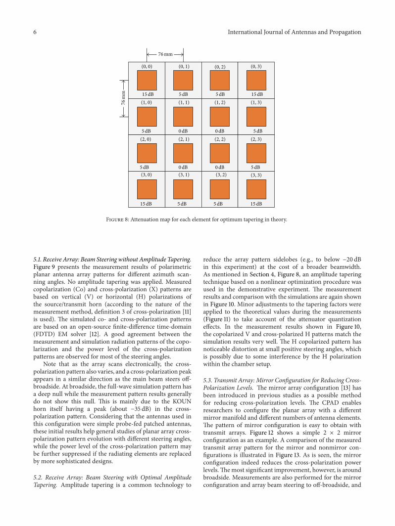
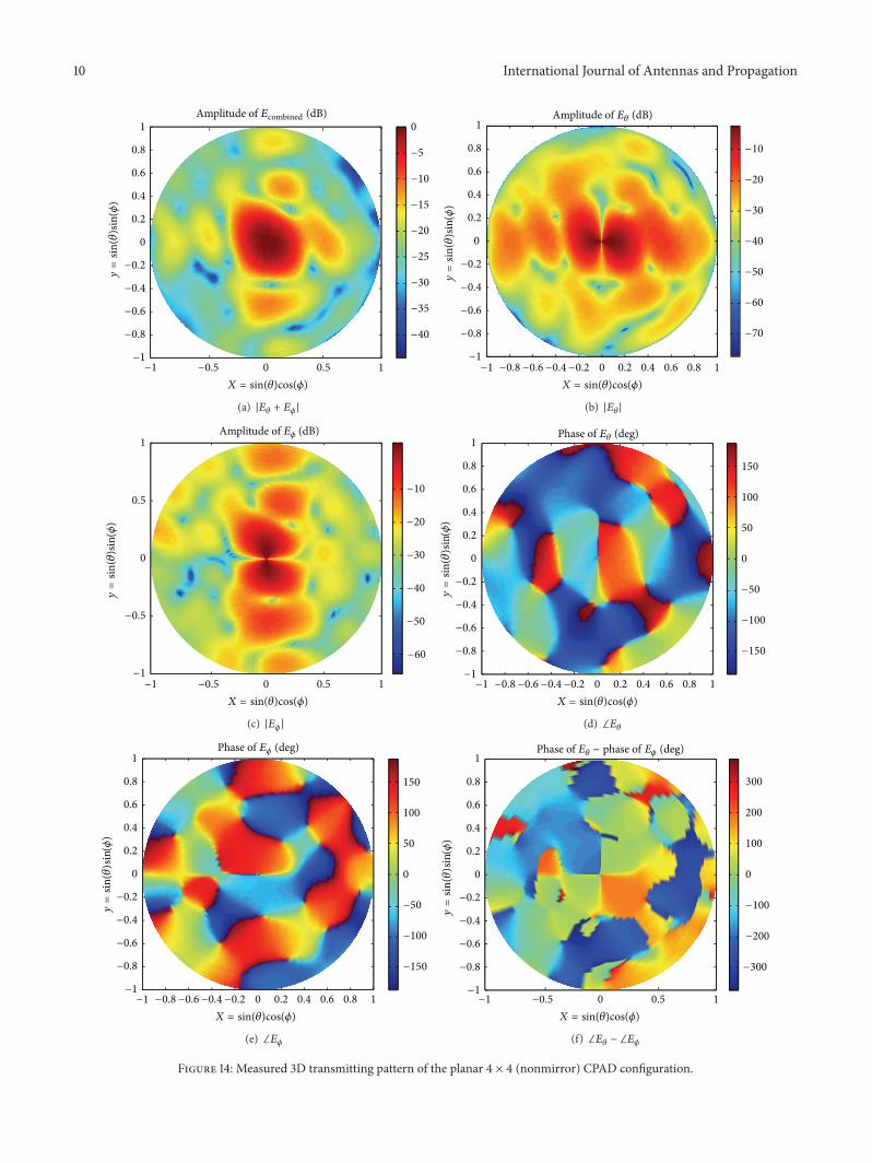
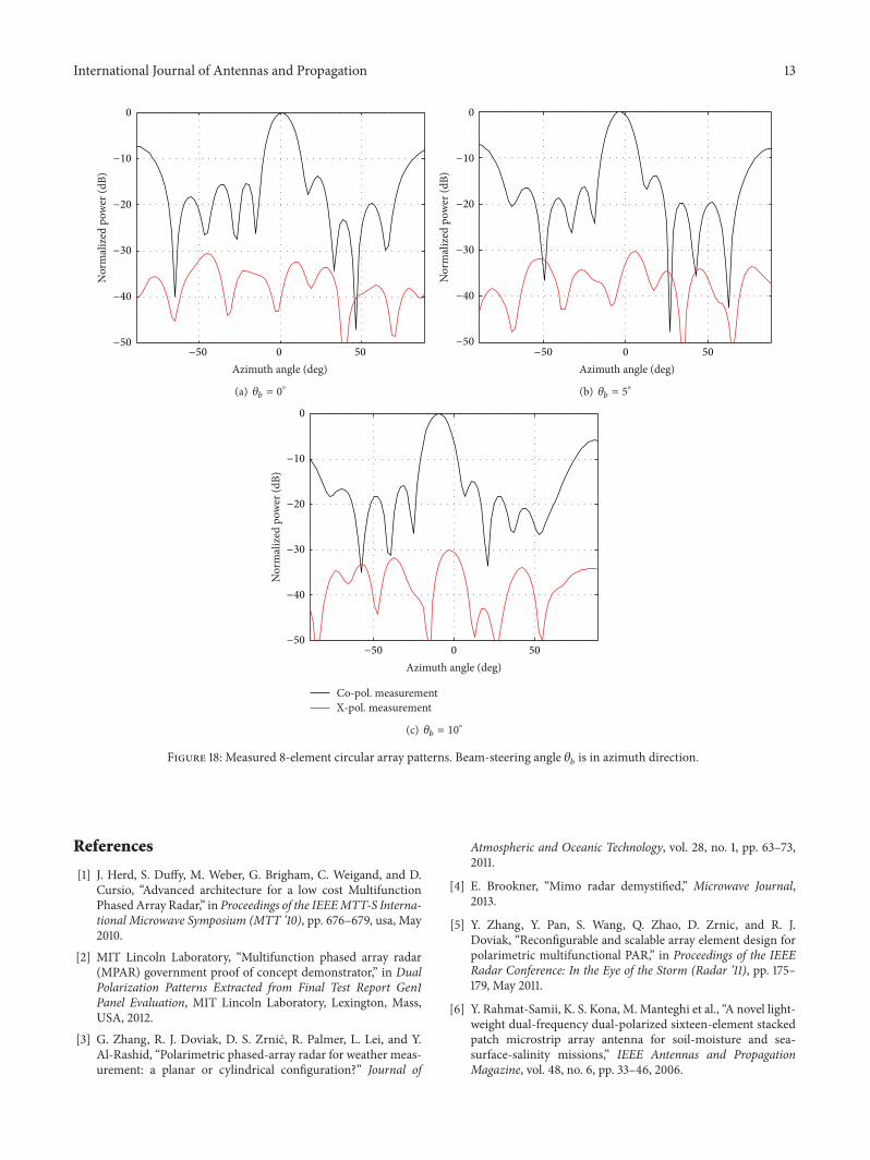

International Journal of
AerospaceEngineeringHindawi Publishing Corporationhttpwwwhindawicom Volume 2014
RoboticsJournal of
Hindawi Publishing Corporationhttpwwwhindawicom Volume 2014
Hindawi Publishing Corporationhttpwwwhindawicom Volume 2014
Active and Passive Electronic Components
Control Scienceand Engineering
Journal of
Hindawi Publishing Corporationhttpwwwhindawicom Volume 2014
International Journal of
RotatingMachinery
Hindawi Publishing Corporationhttpwwwhindawicom Volume 2014
Hindawi Publishing Corporation httpwwwhindawicom
Journal ofEngineeringVolume 2014
Submit your manuscripts athttpwwwhindawicom
VLSI Design
Hindawi Publishing Corporationhttpwwwhindawicom Volume 2014
Hindawi Publishing Corporationhttpwwwhindawicom Volume 2014
Shock and Vibration
Hindawi Publishing Corporationhttpwwwhindawicom Volume 2014
Civil EngineeringAdvances in
Acoustics and VibrationAdvances in
Hindawi Publishing Corporationhttpwwwhindawicom Volume 2014
Hindawi Publishing Corporationhttpwwwhindawicom Volume 2014
Electrical and Computer Engineering
Journal of
Advances inOptoElectronics
Hindawi Publishing Corporation httpwwwhindawicom
Volume 2014
The Scientific World JournalHindawi Publishing Corporation httpwwwhindawicom Volume 2014
SensorsJournal of
Hindawi Publishing Corporationhttpwwwhindawicom Volume 2014
Modelling amp Simulation in EngineeringHindawi Publishing Corporation httpwwwhindawicom Volume 2014
Hindawi Publishing Corporationhttpwwwhindawicom Volume 2014
Chemical EngineeringInternational Journal of Antennas and
Propagation
International Journal of
Hindawi Publishing Corporationhttpwwwhindawicom Volume 2014
Hindawi Publishing Corporationhttpwwwhindawicom Volume 2014
Navigation and Observation
International Journal of
Hindawi Publishing Corporationhttpwwwhindawicom Volume 2014
DistributedSensor Networks
International Journal of