Brackbill J.U., A Continuum Method for Modeling Surface Tension
RESEARCH ACTIVITIES ON HLM THERMAL-HYDRAULICS AND ITS APPLICATION TO ADS DESIGN
X. Cheng, R. Stieglitz and J.U. Knebel Forschungszentrum Karlsruhe, Postfach 3640, 76021 Karlsruhe, Germany
email: [email protected]
Abstract
The Forschungszentrum Karlsruhe has been working on the research and development of an accelerator driven sub-critical system (ADS) cooled by lead-bismuth eutectic (LBE). Related to thermal-hydraulics, a broad spectrum of R&D works is ongoing, from the development of phenomenological models to the design of reactor components. Both experimental and numerical studies are carried out, to fulfill these objectives. In the KArlsruhe Lead LAboratory (KALLA), two test loops are devoted to thermal-hydraulic studies. In addition, significant efforts have been made to develop and to validate numerical tools, which will be applied to analyze the flow and heat transfer behavior of HLM, and to support the design of ADS components.
599
Introduction
Transmutation of minor actinides in an accelerator driven sub-critical system (ADS) is a promising concept to reduce the radioactive waste and its long-term radiotoxicity [1]. In an ADS, heavy liquid metals (HLM), especially lead-bismuth eutectic (LBE), have been considered as coolant for both the sub-critical reactor core and the spallation target. However, large deficiency exists in the basic knowledge of HLM thermal-hydraulics. Some physical models in the existing numerical tools are not valid for HLM flows. There are no reliable and validated heat transfer correlations for ADS prototypical conditions. One of the main objectives of the thermal-hydraulic activities at the Forschungszentrum Karlsruhe is to establish reliable physical models and numerical tools for ADS application. To achieve this goal, both experimental work and theoretical studies are being carried out.
The KArlsruhe Lead LAboratory (KALLA) has been erected from 1999 to 2002 and represents a strategic focal point in the field of LBE technologies in Germany [2]. In the KALLA laboratory experimental works are being carried out on measurement technology development, single effect thermal-hydraulics, prototypical integral systems as well as material researches. KALLA is an open user laboratory for experiments which are relevant for ADS applications. KALLA shall enhance international collaboration and encourage scientific staff exchange.
In addition, significant efforts have been made to develop numerical tools, to analyze the flow and heat transfer behavior of HLM, and to support the design of large scale technical components. Different classes of computer codes are selected, which cover a wide range of applications, i.e. from 3-dimensional Computational Fluid Dynamics (CFD) to system design analysis. One of the long-term goals of the numerical activities is to establish a comprehensive code system suitable for the design of a HLM cooled sub-critical or critical reactor system.
HLM Thermal-hydraulic activities at Forschungszentrum Karlsruhe
Research needs on HLM thermal-hydraulics
Heavy liquid metals have been adapted worldwide as favorable coolants for both the reactor core and the spallation target of an ADS. Design of reactor systems requires comprehensive knowledge of thermal-hydraulic behavior of HLM. The flow velocity of HLM has to be kept below a pre-defined limiting value, to avoid an erosive damage of the structural material. At the same time, a sufficiently effective heat transfer is required, to achieve a low temperature level of the structural material, so that thermal mechanical overload and corrosion damage can be avoided. It is, therefore, fundamental to have tools capable of predicting the distribution of HLM flow and temperature both in the spallation target and in the reactor core. The main thermal-hydraulic activities cover the following subjects:
Experimental thermal-hydraulics
Experimental data base is of crucial importance for the development of physical models. To achieve a reliable data base, advanced experimental techniques, especially measurement techniques, are necessary, which are still missing and require extensive research activities. In addition, comprehensive experimental program will make decisive contribution to the understanding of the thermal-hydraulic behavior and to the design of ADS components.
600

Physical models
Improvement of some physical models, e.g. turbulence and heat transfer, is urgently required for the design of HLM cooled systems. Improved turbulence models are needed by CFD application. Reliable heat transfer correlations are inevitable in the design analysis of fuel assemblies and other large scale heat removal systems.
Numerical tools and design analysis
The overall objective of the activities is the thermal-hydraulic design of ADS, which requires various classes of tools, from fundamental three-dimensional CFD to system analysis approaches. To establish a suitable system of design tools, the Forschungszentrum Karlsruhe is working on the development of new numerical codes.
Experimental Program
Thermal-hydraulic experimental Programs are being conducted in the KALLA laboratory. Two test loops can be utilized for the purpose of thermal-hydraulic studies.
THESYS Loop
The small loop THESYS (Technologies for HEavy metal SYStems) concentrates on the development of fundamental lead-bismuth technologies. The main technical specifications are:
• Maximum temperature: 450°C
• Maximum flow rate: 3.5 m³/h
• Maximum power: 60 kW
A more detailed description of THESYS is given in [2]. The main objectives of THESYS can be divided into three subgroups, i.e.
• Qualification of monitoring and conditioning systems for loop applications such as
− Oxygen control systems (OCS),
− Flow meters, and
− Heat flux simulators.
• Thermal-hydraulic measurement techniques for mean and local quantities, such as temperature, pressure and velocity.
• Thermal-hydraulic data base for physical model development and code validation, such as
− Heat transfer experiments and
− Turbulence measurements.
601
THEADES Loop
The large test loop THEADES (THErmal-hydraulics and ADS DESign) is devoted to both thermal-hydraulic single-effect investigations and ADS prototypical integral studies. The main technical specifications are:
• Maximum temperature: 450°C
• Maximum flow rate: 50 m³/h
• Maximum power: 4.0 MW
The main objectives of the THEADES loop are:
• to study the cooling capability of the beam window of various targets
• to investigate flow behavior in windowless target configurations;
• to contribute to fuel element development for HLM cooled reactors; and
• to provide thermal-hydraulic data base for physical model development and code validation.
Numerical activities
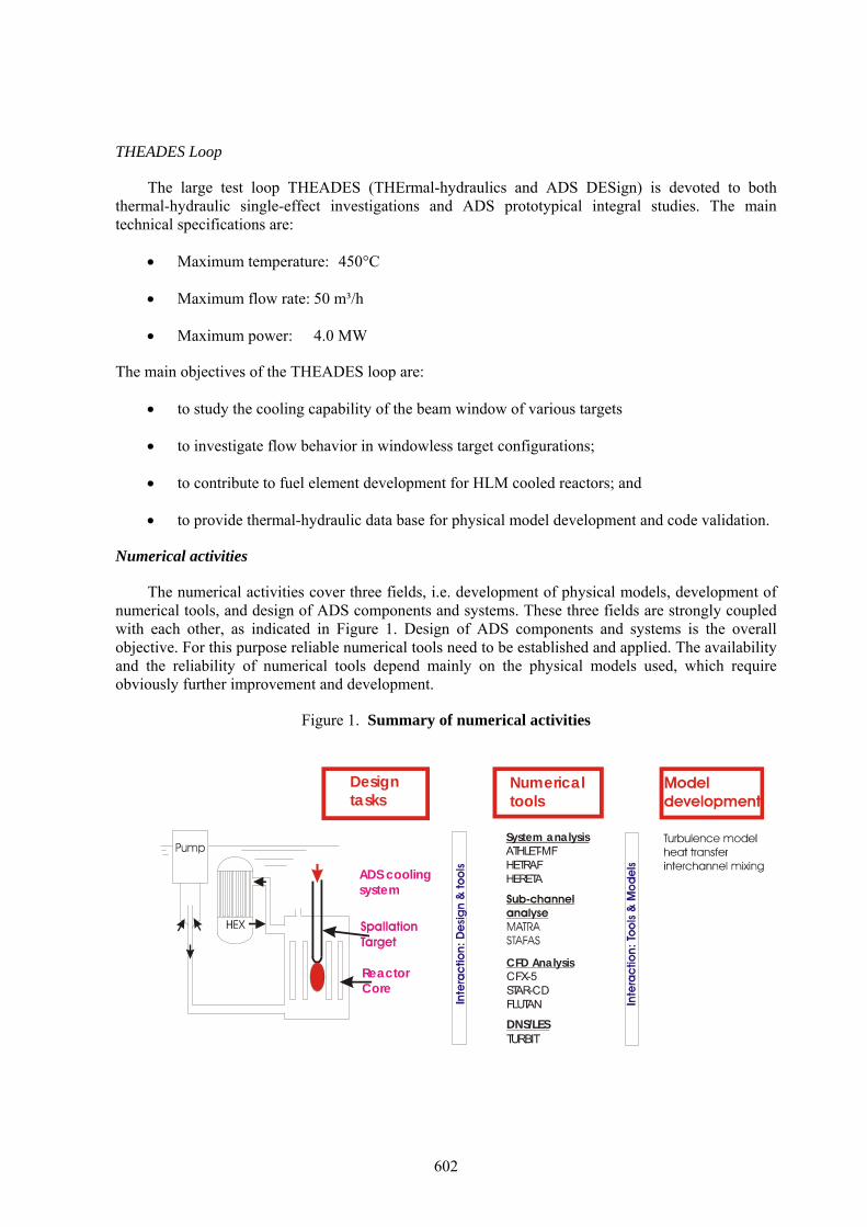
The numerical activities cover three fields, i.e. development of physical models, development of numerical tools, and design of ADS components and systems. These three fields are strongly coupled with each other, as indicated in Figure 1. Design of ADS components and systems is the overall objective. For this purpose reliable numerical tools need to be established and applied. The availability and the reliability of numerical tools depend mainly on the physical models used, which require obviously further improvement and development.
Figure 1. Summary of numerical activities
ReactorCore
ADS coolingsystem
CFD AnalysisCFX-5STAR-CDFLUTAN
System analysisATHLET-MFHETRAFHERETA
Designtasks
Numericaltools
DNS/LESTURBIT
602

Fuel assembly design
In the past, sub-channel analysis has been widely applied to the fuel assembly design purpose. However, there are no sub-channel analysis codes, which are validated for HLM cooled reactors and commercially accessible. Based on the COBRA code, which was originally developed for water cooled reactors, the Korean Atomic Energy Research Institute (KAERI) developed the sub-channel analysis code MATRA, also for designing Na-cooled fast reactors [3]. In the framework of a bilateral collaboration between KAERI and the Forschungszentrum Karlsruhe, the MATRA code will be further developed and modified for HLM cooled reactors. More recently, the sub-channel analysis code STAFAS [4] was developed for single phase coolant flows. For the time being, both codes, STAFAS and MATRA, are selected as reference tools for the sub-channel analysis of HLM cooled fuel assemblies. Furthermore, efforts will be continued to improve physical models used in the sub-channel analysis codes, e.g. heat transfer and inter-channel mixing. For this purpose, accompanying activities of CFD analysis and experimental studies are underway.
Cooling system design
System analysis is required for the design of both the reactor cooling system and the spallation target cooling system. Two independent one-dimensional system codes, HETRAF and HERETA, have been developed for ADS application. In addition, the system analysis code ATHLET-MF [5], which is a modified version of the ATHLET code developed at the Gesellschaft für Reaktorsicherheit (GRS) for water cooled nuclear systems, is applicable to multi-fluid systems, including HLM cooled ADS systems.
Three-dimensional thermal-hydraulics
Application of computational fluid dynamic (CFD) codes is inevitable in designing components of ADS. Intensive application of CFD codes has been realized to the design of the active part of the spallation target [6], where knowledge about the local velocity and temperature distribution in coolant is required, which can only be achieved using the three-dimensional CFD codes. Furthermore, growing attention has been paid to the application of CFD codes to fuel assembly design. In spite of the limitation in computing expenditures, CFD analysis of fuel assemblies would provide valuable information and more reliable models for sub-channel analysis codes.
Model development
The activities of model development cover the following three aspects:
1. Turbulence models for CFD application
− The goal of this work is to derive new turbulence models, especially for energy transport in HLM flows. For this purpose, both the direct numerical simulation code TURBIT and experimental data base will be applied.
2. Heat transfer correlations
− Heat transfer correlations are required for both system analysis and sub-channel analysis. To achieve reliable heat transfer correlations for ADS applications, a thorough review and assessment will be carried out of available experimental and theoretical works in the open literature. With help of the existing works, new test data base and CFD analysis, new heat transfer correlations for ADS conditions will be derived.
603

3. Inter-channel mixing
− To achieve this goal, assessment of experimental data base and application of CFD analysis will make a significant contribution.
Results examples
Experimental studies
Basic heat transfer tests at the THESYS Loop
Experimental investigation was carried out of a thermally developing turbulent lead bismuth flow along a uniformly heated rod (dr=8.2mm) inside a circular pipe (dp=60mm), as indicated in figure 2. During the experiment the temperature and velocity field around the traversable heated rod is measured using thermo-couples and Pitot tube, respectively.
Figure 2. Basic heat transfer experiment at the THESYS loop [7].
In figure 3 the measured radial
distribution of axial velocity and temperature rise to the inflow temperature is shown for various axial positions z/dp. Here z stands for the axial distance between the rod tip and the measurement location. The viscous boundary layer can be partially captured by the Pitot tube measurement. The results show that the viscous boundary layer hardly increases in its radial extension as the flow proceeds downstream. The temperature rise increases monotonically with increasing z/dp and also the thickness of the temperature boundary layer grows downstream. This kind of data can be used for assessing the applicability of CFD codes and for improving physical models.
-1012345678
0102030
radial position [mm]
tem
pera
ture
rise
[°C
]
0.20.220.240.260.280.3
0.320.34
velo
city
[m/s
]
T at 1/2 T at 1/4 T at 1/8 T at 0v at 1/2 v at 1/4v at 1/8 v at 0
Hea
ted
Rod
Figure 3. Measured temperature and velocity
distribution at Re= [7] 510
604

Heated jet tests at the THEADES Loop
In the frame of the MEGAPIE project, two different kinds of experiments were carried out at the THEADES loop. In the first test, the so called heated jet test, a hot LBE flow is realized through the bypass jet. The turbulent mixing behavior of the hot jet with the cold main flow, especially in the region close to the window surface, is investigated. Figure 4 shows an example of the measured temperature distribution as a function of the location along the lower hemisphere for varying main flow rates [8]. The inlet temperature of the jet into the test module is 360°C, and the temperature of the main flow into the test module is 300°C. The bypass jet flow rate is 1.5m³/h.
Figure 4. Measured temperature along the window surface at various main flow rates [8]
9 m³/h; Δ 12 m³/h; ∇ 15 m³/h;
18m³/h; ◊ 21 m³/h; 24 m³/h
The effect of the hot jet on the temperature field close to the window surface is clearly identified. The lower the main flow rate is, the larger is the zone affected by the hot jet. For a main flow rate lower than 12m3/h, the jet even enters the opposite side of the annular gap (s<52mm), which is expressed by a temperature increase there. At high mass flow rates, the temperature profiles show a cold spot between two peaks. This indicates a detachment of the hot spot from the window surface.
Numerical studies and design analysis
Heat transfer correlations
Although numerical tools for various purposes have been established, it is well agreed that reliably validated physical models are still missing, especially related to turbulent heat transfer. Both system analysis and sub-channel analysis codes require the application of heat transfer correlations. To achieve basic knowledge about the turbulent heat transfer, a thorough literature review was made on turbulent heat transfer in liquid metals both in circular tubes and in rod bundles [9, 10].
605

Figure 5 compares the Nusselt number calculated with different correlations available in the open literature. The correlation of Lyon with a turbulent Prandtl number of 1.0 gives much higher heat transfer coefficients than other correlations. Both correlations of Skupinski and Sleicher, based on test data of NaK, agree well with each other and give higher heat transfer coefficients than other correlations proposed for heavy liquid metal flows. In the low Peclet number region, both correlations of Kirillov and Ibragimov, proposed for LBE flows, show a better heat transfer than the correlation of Stromquist. Based on a thorough assessment of existing studies and additional CFD analysis, the following correlation was proposed for heat transfer of LBE flow in circular tubes.
0
5
10
15
20
25
0 1000 2000 3000Peclet number [-]
Nus
selt
num
ber [
-]
Lyon, Prt=1SkupinskiSleicherKirillovIbragimovStromquist
Figure 5. Heat transfer correlations for circular tubes [9]
(1) 80.0018.0 PeANu +=
with
⎪⎩
⎪⎨
⎧
≥≤≤⋅−
≤
= −
20006.3200010001094.5
10005.44
PePePe
PeA
Design analysis of target cooling systems
Design analysis of the cooling system of two spallation targets was carried out in the past, i.e. the MEGAPIE target and the XADS target. In the frame of the MEGAPIE project, the HETRAF code was applied to investigate the transient behavior of the target cooling system, as sketched in figure 6. Figure 7 shows the LBE temperature at the heat exchanger exit for beam interrupt transients with and without protection, respectively. In the unprotected case, no actions are taken, whereas in the protected case, the control valve CV2 is opened in 5 s after the start of beam interrupt, and at the same time the control valve CV3 is closed. In the unprotected case, the LBE temperature decreases and reaches the freezing point in about 4 minutes. In the protected case, the LBE temperature can be kept far above the freezing point (123°C), and blockage of the flow path, subsequently, the damage of the target is avoided.
606

Hot fluid tank(180°C)
Activezone
Target HEX
D2O30°C10 l/s
Organic fluid10 l/s
Pb-Bi
2nd HEX
Beam window
CV1Cv2
Cv3
Cv4
Figure 6. Sketch of the MEGAPIE
cooling system
100
150
200
250
300
350
0 50 100 150 200 250 300
Time [s]
Tem
pera
ture
[°C
]
unprotectedprotected
Figure 7. LBE temperature at the HEX exit under protected and unprotected beam trip
conditions
The system analysis code, ATHLET-MF, has been applied to the design analysis of the cooling system of the spallation target of the European experimental ADS (XADS), as sketched in figure 8. Figure 9 shows the transient behavioor of LBE mass flow rate and temperature under start-up conditions. In this analysis it is assumed that the heat exchanger is put into operation at the beginning of the transient and the beam power (2.6MW) is switched on after 500s. The initial temperature of the whole target system is assumed to be 300°C, and initial mass flow rate to be zero. After the transient begins, LBE is cooled down by the secondary side of HEX. Mass flow rate increases due to the increasing driven force of natural circulation resulting from the difference of fluid density between the inner channel and the outer channel. The mass flow rate reaches its peak before the cooled fluid enters the inner channel and then decreases. Stable system mass flow rate and fluid temperature is achieved after the heat removal in HEX is balanced by the heat in-flow from the reactor pool to the outer channel. The mass flow rate and fluid temperature shows a sharp increase after the switch-on of the beam power. Another steady state with higher mass flow rate and fluid temperature is established about 100s after the switch-on of the beam power.
607
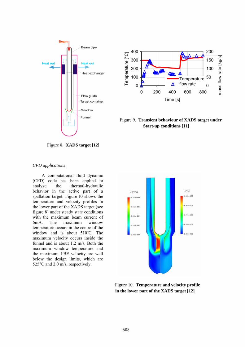
Beam
Beam pipe
Heat out
Heat exchanger
Flow guide
Heat out
Target container
Window
Funnel
Figure 8. XADS target [12]
0
100
200
300
400
0 200 400 600 800
Time [s]
Tem
pera
ture
[°C
]
0
50
100
150
200
Temperatureflow rate
mas
s flo
w ra
te [k
g/s]
Figure 9. Transient behaviour of XADS target under Start-up conditions [11]
CFD applications
A computational fluid dynamic (CFD) code has been applied to analyze the thermal-hydraulic behavior in the active part of a spallation target. Figure 10 shows the temperature and velocity profiles in the lower part of the XADS target (see figure 8) under steady state conditions with the maximum beam current of 6mA. The maximum window temperature occurs in the centre of the window and is about 510oC. The maximum velocity occurs inside the funnel and is about 1.2 m/s. Both the maximum window temperature and the maximum LBE velocity are well below the design limits, which are 525°C and 2.0 m/s, respectively.
Figure 10. Temperature and velocity profile in the lower part of the XADS target [12]
608

In addition, CFD codes were applied to investigate heat transfer behavior in both circular tubes and in rod bundles. Figure 11 shows the effect of turbulent Prandtl number on Nusselt number in circular tubes. The CFD results show clearly a decrease in Nusselt number with increasing turbulent Prandtl number. There is a good agreement between the CFX results and the Lyon model. For the flow condition considered in figure 11 (Pe=1200), the model of Kirillov agrees well with both the CFX data and the Lyon model with a turbulent Prandtl number of about 3.0.
0
5
10
15
20
0.0 1.0 2.0 3.0 4.0 5.0
Turbulent Prandtl number [-]
Nus
selt
num
ber [
-] CFXLyonKirillov
Figure 11. Effect of turbulent Prandtl number on Nusselt number in tubes [9]
0
5
10
15
20
25
30
0.0 1.0 2.0 3.0 4.0 5.0
Turbulent Prandtl number [-]N
usse
lt nu
mbe
r [-]
CFX-5.6LyonMareska
Figure 12. Effect of turbulent Prandtl number on Nusselt number in rod bundles [10]
Figure 12 compares the CFX results with the correlations of Mareska and Lyon for rod bundles.
Again, Nusselt number decreases with increasing turbulent Prandtl number. An excellent agreement is observed between the CFX results and the Mareska’s correlation over a wide range of turbulent Prandtl number. The correlation of Lyon for circular tubes under-predicts strongly the heat transfer in rod bundles.
Summary
Due to the favorable properties, heavy liquid metals, e.g. lead or lead bismuth eutectic, have been considered worldwide as reference coolants for the accelerator driven sub-critical system (ADS). Since many years, the Forschungszentrum Karlsruhe has been engaged in the development of LBE-cooled ADS. A broad spectrum of thermal-hydraulic activities is ongoing, from the development of phenomenological models to the design of reactor components. Both experimental and numerical studies are carried out, to fulfill these objectives. All the activities are tightly coupled with international collaborations.
The Karlsruhe lead laboratory (KALLA) has been constructed at the Forschungszentrum Karlsruhe and becomes a strategically crucial facility in the field of LBE technologies. Basic thermal-hydraulic tests and verification tests of large scale ADS components will be carried out. Important data base will be produced for the development of physical models and for the validation of numerical tools. KALLA is an open user laboratory for experiments which are relevant for ADS applications, and will enhance international collaboration and encourage scientific staff exchange.
In parallel to the experimental activities, significant efforts have been made and will be continued to develop a comprehensive system of numerical tools suitable for ADS design applications. This tool system contains various classes of tools, from fundamental three-dimensional CFD to system analysis approaches, and shall be applied to design analysis of single components and complex heat removal systems. At the same time, activities are also ongoing on the development of new physical models and on the validation of existing numerical tools.
609

The entire thermal-hydraulic activities at the Forschungszentrum Karlsruhe cover four subjects, such as experimental thermal-hydraulics, physical models, numerical tools and design analysis. The complete test facilities in KALLA and the comprehensive numerical tool system will provide an excellent opportunity to training young nuclear engineers and to make a significant contribution to maintain the know-how in nuclear engineering.
References
[1] J.U. Knebel, G. Heusener, Research on Transmutation and Accelerator Driven Systems at the Forschungszentrum Karlsruhe, Atomwirtschaft-Atomtechnik, 45 (2000), pp.350- 358, 2000. [2] J.U. Knebel, et al., Thermal-hydraulic and Material Specific Investigations into the Realization of an Accelerator Driven System (ADS) to Transmute Minor Actinides, Wissenschaftliche Berichte, FZKA 6618, September 2001. [3] Y. J. Yoo, D. H. Hwang, and D. S. Sohn, Development of a Sub-channal Analysis Code MATRA Applicable to PWRs and ALMRs, Journal of Korean Nuclear Society, Vol. 31(3), p.314, 1999. [4] X. Cheng, T. Schulenberg, Design Analysis of Core Assemblies for Supercritical Pressure Conditions, to be published in Nuclear Engineering and Design 2003. [5] G. Lerchl, H. Austregesilo, User’s Manual, ATHLET Mod 1.2 Cycle D, GRS-P-1, Vol.1, Res.2b, September 2001. [6] J.U. Knebel, X. Cheng, N.I. Tak, Thermal-hydraulic Design of the MEGAPIE Spallation Target, 5th Topical Meeting on Nuclear Applications of Accelerator Technology, Reno, November 11-16, 2001. [7] C.H. Lefhalm, H. Piecha, R. Stieglitz, Turbulent heat transfer along a heated rod in liquid Lead bismuth flow, Jahrestagung Kerntechnik, May 25.-27., 2004, Düsseldorf, paper 218. [8] M. Daubner, F. Fellmoser, C.-H. Lefhalm and R. Stieglitz, Turbulent HEAT transfer in liquid metals - the MEGAPIE Heated jet experiments, Jahrestagung Kerntechnik, May 25.-27., 2004, Düsseldorf, paper 218. [9] X. Cheng, A. Batta, H.Y. Chen, N.I. Tak , Turbulent Heat Transfer to Heavy Liquid Metals in Circular Tubes, 2004 ASME Heat Transfer and Fluids Engineering Summer Conference, July 11-15, 2004, Charlotte, North Carolina, USA, Paper: HT-FED2004- 56562. [10] X. Cheng, N.I. Tak, Turbulent heat transfer to heavy liquid metal in bare rod bundles, 11th International Topical Meeting on Nuclear Reactor Thermal-Hydraulics (NURETH- 11), Popes Palace Conference Center, Avignon, France, October 2-6, 2005. [11] H.Y. Chen, X. Cheng, H.J. Neitzel, Application of ATHLET Code to Heavy Liquid Metal Cooled Systems, Jahrestagung Kerntechnik, May 25.-27., 2004, Düsseldorf, paper 202. [12] N.I. Tak, H.-J. Neitzel, X. Cheng, Numerical simulation on lower part of window target for Experimental ADS, Jahrestagung Kerntechnik, May 25.-27., 2004, Düsseldorf, paper 206.
610