(requires C15-20 or C15-22)
4
armfield.co.uk UK office - email: sales@armfield.co.uk tel: +44 (0) 1425 478781 (for ROW) USA office - email: info@armfield.inc tel: +1 (609) 208-2800 (USA only) We reserve the right to amend these specifications without prior notice. E&OE © 2019 Armfield Ltd. All Rights Reserved Issue: 2 FM Computer Controlled Subsonic Wind Tunnel - C15 Inclined Manometer Bank Full Computer Control As Standard Lifting Drag Balance C15-13 Features Fluid Mechanics C SERIES Issue: PROVISIONAL Applications URL: http://www.armfield.co.uk/f1 CE IP ChE ME u Computer controlled benchtop wind tunnel u 150mm x 150mm x 455mm working section u Transparent working section for visibility u Wide range of models for both Aerodynamics and Fluid Mechanics u Choice of water or electronic manometer banks u 9.4:1 contraction ratio wind tunnel design proving excellent uniform flow u Simple flow visualisation technique incorporated COMPUTER CONTROL & DATA CAPTURE AS STANDARD A compact benchtop wind tunnel, with visible working section. A wide range of accessories and instrumentation options are available, allowing a comprehensive study of Subsonic Aerodynamics and Fluid Mechanics.
Transcript of (requires C15-20 or C15-22)

armfield.co.uk
UK office - email: [email protected] tel: +44 (0) 1425 478781 (for ROW)USA office - email: [email protected] tel: +1 (609) 208-2800 (USA only)
We reserve the right to amend these specif ications without prior notice. E&OE © 2019 Armfield Ltd. All Rights Reserved
Issue: 2FM SERIES
Computer Controlled Subsonic Wind Tunnel - C15
Inclined Manometer BankFull Computer Control As Standard Lifting Drag Balance C15-13
Features
Fluid Mechanics
C SERIES
Issue: PROVISIONAL Applications
URL: http://www.armfield.co.uk/f1 CE IPChE ME
u Computer controlled benchtop wind tunnel u 150mm x 150mm x 455mm working section u Transparent working section for visibility u Wide range of models for both Aerodynamics and Fluid Mechanics
u Choice of water or electronic manometer banks u 9.4:1 contraction ratio wind tunnel design proving
excellent uniform flow u Simple flow visualisation technique incorporated
COMPUTER CONTROL & DATA CAPTURE AS STANDARDA compact benchtop wind tunnel, with visible working section.
A wide range of accessories and instrumentation options are available, allowing a comprehensive study of Subsonic Aerodynamics and Fluid Mechanics.

Fluid Mechanics
C15-20: LIft & Drag Aerofoil (requires C15-13)
A plain symmetrical aerofoil to NACA 0015 profile, incorporating a mounting rod that allows it to be installed on the C15-13 Lift & Drag Balance, thus allowing the lift and drag to be measured with the aerofoil at different angles of attack.
C15-11: Inclined Manometer Bank
C15-12: Electronic Manometer Bank
C15-13: Lift and Drag Balance (requires C15-20 or C15-22)
C15-14: Pitot Static Tube (requires C15-11 or C15-12)
The bank of 13 transparent tubes inclined at 30° to measure small pressure differences (0–160 mm H2O). It includes a water reservoir with screw operated displacer to allow rapid adjustment of the datum level in the manometer, and is fitted with quick release connectors for rapid connection to models and instruments. Water is used as the manometer fluid for safety and convenience in use.
An electronic console incorporating 16 differential pressure sensors, each with a range of 0-178 mm H2O. (It connects to the control PC using a second USB port, and the readings are fully integrated with the wind tunnel control software.)
A 2-component, electronic balance used to measure the lift and drag on appropriate models (not used with models having multiple internal tapping points). The lift and drag models connect to the balance using a simple fixing that ensures correct orientation of the model.
A small Pitot static tube mounted in a bush that can be located in the roof of the working section at three alternative positions, i.e. the start of the working section and upstream and downstream of the model mounting position.
C15-15: Wake Survey Rake (requires C15-11 or C15-12)
The rake consists of 10 tubes positioned vertically in a row and pointing towards the airflow. The rake is mounted downstream of the model being used.

USA office - email: [email protected]: +1 (609) 208-2800 (USA only)
UK office - email: [email protected] tel: +44 (0)1425 478781 (for ROW)
Web: armfield.co.uk©2019 Armfield Ltd. All Rights Reserved Part of Judges Scientific PLC
ISO 9001:2015
Fluid Mechanics
C15-24: Bernoulli Apparatus (requires C15-11 or C15-12)
C15-25: Boundary Layer Plate (requires C15-11 or C15-12)
A flat plate, with a bevelled leading edge, that is mounted vertically in the working section via the removable floor. A flattened Pitot tube, mounted on a traversing micrometer, allows the air velocity to be measured at different distances from the surface of the plate.A smooth plate and artificially roughened plate (above) are included to show the difference between laminar and turbulent boundary layers. The flexible tubing from the Pitot tube incorporates a quick release connector.
C15-21: Pressure Wing (requires C15-11 or C15-12)
C15-22 Drag Models (requires C15-13)
C15-23: Pressure Cylinder (requires C15-11 or C15-12)
A symmetrical aerofoil incorporating 10 tapping points distributed along the wing profile on one side, which allows the pressure distribution to be measured from the leading edge to the trailing edge.The pressure distribution on the upper and lower surface can be obtained by inclining the aerofoil at positive and negative angles of attack. Machined to NACA 0015 profile, the aerofoil has the same section as the C15-20 to allow direct comparison of pressure distribution with the lift characteristics.
Seven different models are provided for use with the C15-13 Lift and Drag Balance for investigations into the influence of shape on the drag forces. Five models are supplied with a common equatorial diameter of 50mm, thus all presenting the same cross section to the airflow: Sphere - Hemisphere, convex to airflow - Hemisphere, concave to airflow - Circular disk - Streamlined shape. Additionally a dimpled golf ball and plain sphere demonstrate the difference in drag force due to the dimples.
A plain cylinder, 30mm diameter, incorporating 10 equi-spaced tapping points around half of the circumference that allow the pressure distribution around the cylinder to be measured.The cylinder can be rotated through 180° to plot the pressure distribution over the whole circumference.
A Venturi profile that is installed in the working section of the tunnel via the removable floor. The Venturi incorporates 11 pressure tappings in the floor, connected via flexible tubing to quick release connectors. The Venturi occupies the full height of the working section and the width varies from 150mm (full width of the working section) at the inlet and outlet to 100mm at the throat. It is manufactured from clear acrylic for full visualisation.
C15-25: Boundary Layer Plate (requires C15-11 or C15-12) A selection of components that allow alternative models to be constructed by the user. Includes a floor panel, a circular hatch and a set of connectors with appropriate flexible tubing.
Products certified
An ISO 9001:2015 Company
armfield.co.uk
Knowledge base> 28 years’ expertise in research & development technology > 50 years’ providing engaging engineering teaching equipment
Benefit from our experience, just call or email to discuss your laboratory needs, latest project or application.
AftercareInstallation Commissioning TrainingService and maintenance Support: armfieldassist.com
Electrical supply:
u C15-10-A: 220-240V/1/Phase, 50Hz, 10Amps u C15-10-G: 220-240V/1/Phase, 60Hz, 10Amps
G version has optional 1.5kVA transformer available to accommodate 120V/1Ph/60Hz supply.
The user must have access to a PC with a free USB port, running Windows 98, 2000, ME or XP. An additional USB port will be required when using the optional C15-12.
Requirements Scale
COLD HOT
PC IFD 7
FM 6X
1Ph
COLD USB
oil DRAIN
HEARING PROTECTION
EXTRACTOR
COLD HOT
PC IFD 7
FM 6X
1Ph
COLD USB
oil DRAIN
HEARING PROTECTION
EXTRACTOR
PC USB
C15-10-A Computer Controlled Wind TunnelC15-10-G Computer Controlled Wind TunnelC15-11 Inclined Manometer BankC15-12 Electronic Manometer BankC15-13 Lift and Drag Balance (requires C15-20 or C15-22)C15-14 Pitot Static Tube (requires C15-11 or C15-12)C15-15 Wake Survey Rake (requires C15-11 or C15-12) C15-20 Lift & Drag Aerofoil (requires C15-13)C15-21 Pressure Wing (requires C15-11 or C15-12) C15-22 Drag Models (requires C15-13) C15-23 Pressure Cylinder (requires C15-11 or C15-12) C15-24 Bernoulli Apparatus (requires C15-11 or C15-12)C15-25 Boundary Layer Plate (requires C15-11 or C15-12) C15-26 Project Kit
Ordering codes
C15-10 Square test section, nominally 150 x 150mm, length 455 mm Air velocity in the test section variable from 0 to 34m/s (note: some models can only be used at lower velocity) Profiled inlet with a 9.4:1 (nominal) contraction ratio
C15-11 Tube length 320mm Inclination 30° Measurement range 0-160 mm H2O C15-12 16 channels 0-178 mm H2O (differential) C15-13 Lift force 3.4N at model Drag force 3.4N at model
Inclination +/- 45° C15-20 Aerofoil NACA 0015 Cord length 61.5mm Thickness 9.2mm C15-22 Equatorial diameters:
Large models 50mm Golf ball and small sphere 43mm
C15-23 Cylinder diameter 30mm Tapping spacing 20° C15-24 Throat width 100mm
Upstream/downstream width 150mm
Ordering specification
The C15-10 is a computer controlled compact wind tunnel designed for benchtop operation. Air is drawn through the working section by a variable speed fan at the discharge end of the tunnel providing up to 34m/s air velocity.A honeycomb flow straightener is incorporated at the inlet, and a 9:4:1 contraction ratio which ensures an uniform airflow through the working section. The working section is fabricated from clear acrylic to provide optimum visibility of the models, and appropriate model connection points are included in the side wall and roof of the working section to provide ease of use.The wind tunnel is supplied as standard with an in-depth software interface providing control of the fan speed and additionally display important parameters such as static pressure and air velocity. The Armfield C15-10 can be optionally supplied with two variants of
manometry banks, a 13 tube water manometer used to simultaneously display differential pressure or a sixteen channel electronic manometer allowing direct integration into the supplied software.The wind tunnel can be supplied with a range of optional accessories including drag bodies, lift bodies, pressure distribution, boundary layers studies and measuring instruments.The optional models are mounted through a circular hatch using quick release clamps (120mm diameter). The placement of the optional models has been designed to minimise the disturbance to air flow and reduction in flow rate, whilst incorporating an angular scale allowing the model to be manually rotated to known angles. The working section incorporates an innovative technique for flow visualisation around any of the optional models avoiding the need for either smoke or dry ice. A lightweight twine follows the flow contour around the model and shows if and where boundary layer separation (breakaway) occurs.
Description
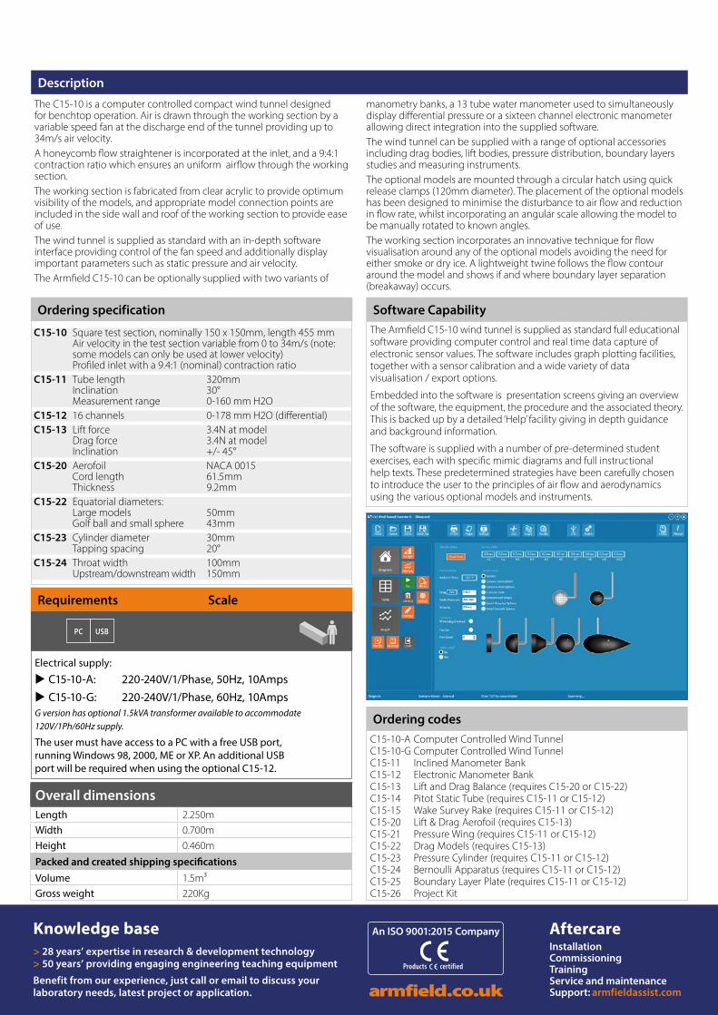
The Armfield C15-10 wind tunnel is supplied as standard full educational software providing computer control and real time data capture of electronic sensor values. The software includes graph plotting facilities, together with a sensor calibration and a wide variety of data visualisation / export options.
Embedded into the software is presentation screens giving an overview of the software, the equipment, the procedure and the associated theory. This is backed up by a detailed ‘Help’ facility giving in depth guidance and background information.
The software is supplied with a number of pre-determined student exercises, each with specific mimic diagrams and full instructional help texts. These predetermined strategies have been carefully chosen to introduce the user to the principles of air flow and aerodynamics using the various optional models and instruments.
Software Capability
Overall dimensionsLength 2.250mWidth 0.700mHeight 0.460m
Packed and created shipping specificationsVolume 1.5m³Gross weight 220Kg