Requirements - Purdue University - Department of · Web viewClasses are the set of objects...
48
UDP Host Design Document Motorola 1 Version 1.0 Nobo Akiya Hui Ai Chan Huan Chang Chiu Keung Sik Kim Sirinya Laiteerapong Mary Rebecca Lee November 13, 2000
Transcript of Requirements - Purdue University - Department of · Web viewClasses are the set of objects...

UDP Host
Design DocumentMotorola 1
Version 1.0
Nobo Akiya Hui Ai Chan
Huan Chang ChiuKeung Sik Kim
Sirinya LaiteerapongMary Rebecca LeeNovember 13, 2000

Table of Contents
0.1 LIST OF FIGURES.........................................................................................................................4
0.2 LIST OF TABLES...........................................................................................................................4
1 INTRODUCTION..............................................................................................................................5
2 SYSTEM FUNCTIONS.....................................................................................................................6
2.1 BASIC FUNCTIONS..........................................................................................................................62.1.1 ECHO TRAFFIC FUNCTIONS.........................................................................................................62.1.2 GENERATE STATISTICS FUNCTIONS............................................................................................7
3 SYSTEM ATTRIBUTES...................................................................................................................7
4 USE CASES........................................................................................................................................8
4.1 SET OPTIONS..................................................................................................................................84.1.2 Option Reset Statistics............................................................................................................94.1.3 Option Message Window........................................................................................................94.1.4 Option Logging.......................................................................................................................94.1.5 Option Echo Feature.............................................................................................................10
4.1.5.1 Message Spiking.............................................................................................................104.1.5.2 Time Based Activity.......................................................................................................104.1.5.3 Multicast.........................................................................................................................10
4.1.6 Option Echo String................................................................................................................104.2 SET CONFIGURATION...................................................................................................................10
4.2.1 Set Configuration..................................................................................................................114.2.2 IP address configuration.......................................................................................................114.2.3 Port configuration.................................................................................................................11
4.3 ENABLE/DISABLE LISTENING AND STATISTICS.............................................................................124.3.1 Enable/Disable listening and statistics.................................................................................12
4.4 SEND AND RECEIVE PACKETS......................................................................................................124.4.1 Send and Receive..................................................................................................................12
4.4.1.1 Echo Spike Message.......................................................................................................134.4.1.2 Echo Time Based Message.............................................................................................134.4.1.3 Echo Multicast................................................................................................................134.4.1.4 Echo Once......................................................................................................................14
4.5 USE CASE RANK..........................................................................................................................144.5.1 Qualities Used to base rank..................................................................................................144.5.3 Use Case Results...................................................................................................................14
5 CONCEPTUAL DIAGRAM...........................................................................................................15
6 SYSTEM BEHAVIOR.....................................................................................................................15
6.1 COLLABORATION DIAGRAMS.......................................................................................................156.1.1 Message Spiking....................................................................................................................166.1.2 Enable listening and statistics...............................................................................................166.1.3 Set Logging Option...............................................................................................................176.1.4 Time Based Activity...............................................................................................................17
6.2 SYSTEM OPERATION CONTRACTS................................................................................................186.2.1 Contract for Enable/Disable Listening & Statistics Use Case.............................................19
2
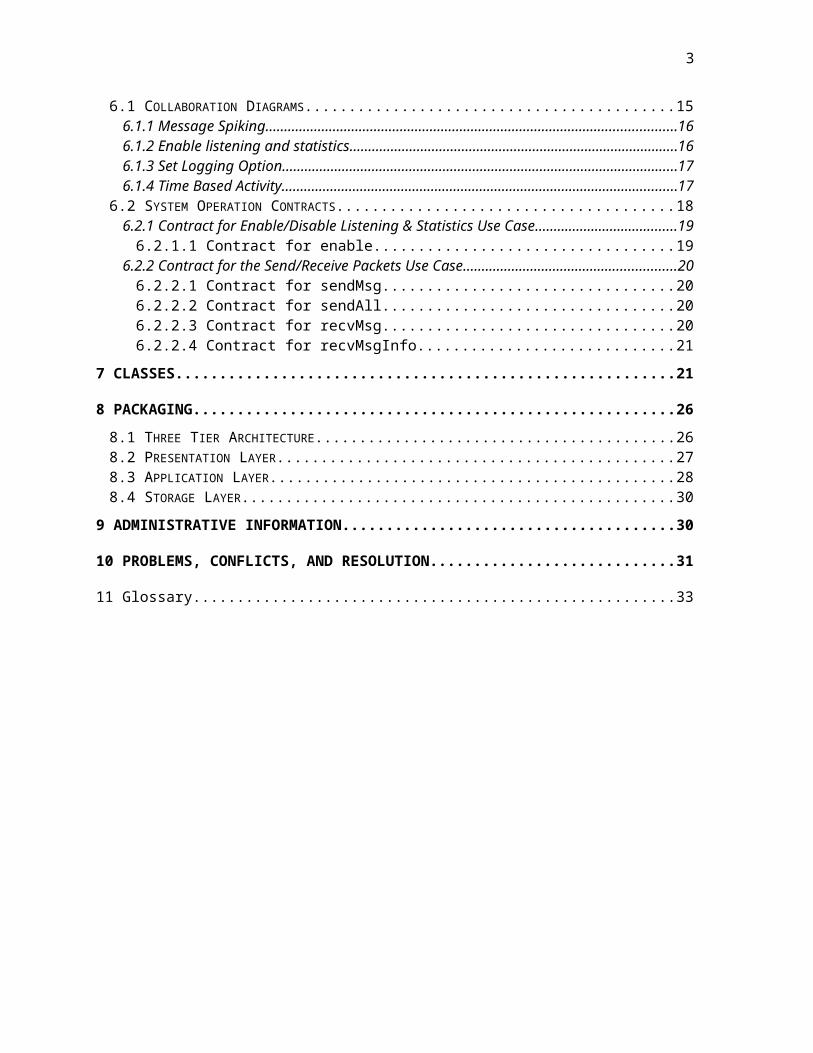
6.2.1.1 Contract for enable.........................................................................................................196.2.2 Contract for the Send/Receive Packets Use Case.................................................................20
6.2.2.1 Contract for sendMsg.....................................................................................................206.2.2.2 Contract for sendAll.......................................................................................................206.2.2.3 Contract for recvMsg......................................................................................................206.2.2.4 Contract for recvMsgInfo...............................................................................................21
7 CLASSES..........................................................................................................................................21
8 PACKAGING...................................................................................................................................26
8.1 THREE TIER ARCHITECTURE........................................................................................................268.2 PRESENTATION LAYER.................................................................................................................278.3 APPLICATION LAYER....................................................................................................................288.4 STORAGE LAYER..........................................................................................................................30
9 ADMINISTRATIVE INFORMATION.........................................................................................30
10 PROBLEMS, CONFLICTS, AND RESOLUTION....................................................................31
11 Glossary............................................................................................................................................33
3
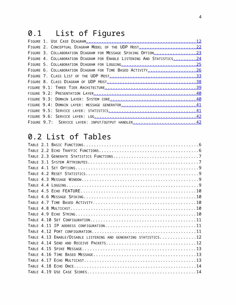
0.1 List of FiguresFIGURE 1. USE CASE DIAGRAM ............................................................................................................... 8 FIGURE 2. CONCEPTUAL DIAGRAM MODEL OF THE UDP HOST ........................................................... 15 FIGURE 3. COLLABORATION DIAGRAM FOR MESSAGE SPIKING OPTION .............................................. 16 FIGURE 4. COLLABORATION DIAGRAM FOR ENABLE LISTENING AND STATISTICS .............................. 17 FIGURE 5. COLLABORATION DIAGRAM FOR LOGGING .......................................................................... 17 FIGURE 6. COLLABORATION DIAGRAM FOR TIME BASED ACTIVITY .................................................... 18 FIGURE 7. CLASS LIST OF THE UDP HOST ............................................................................................ 23 FIGURE 8. CLASS DIAGRAM OF UDP HOST ........................................................................................... 26 FIGURE 9.1: THREE TIER ARCHITECTURE .............................................................................................. 27 FIGURE 9.2: PRESENTATION LAYER ....................................................................................................... 28 FIGURE 9.3: DOMAIN LAYER: SYSTEM CORE ......................................................................................... 28 FIGURE 9.4: DOMAIN LAYER: MESSAGE GENERATOR ............................................................................ 29 FIGURE 9.5: SERVICE LAYER: STATISTICS .............................................................................................. 29 FIGURE 9.6: SERVICE LAYER: LOG ......................................................................................................... 29 FIGURE 9.7: SERVICE LAYER: INPUT/OUTPUT HANDLER ....................................................................... 30
0.2 List of TablesTABLE 2.1 BASIC FUNCTIONS..................................................................................................................6TABLE 2.2 ECHO TRAFFIC FUNCTIONS....................................................................................................6TABLE 2.3 GENERATE STATISTICS FUNCTIONS.......................................................................................7TABLE 3.1 SYSTEM ATTRIBUTES.............................................................................................................7TABLE 4.1 SET OPTIONS..........................................................................................................................9TABLE 4.2 RESET STATISTICS..................................................................................................................9TABLE 4.3 MESSAGE WINDOW................................................................................................................9TABLE 4.4 LOGGING................................................................................................................................9TABLE 4.5 ECHO FEATURE.................................................................................................................10TABLE 4.6 MESSAGE SPIKING...............................................................................................................10TABLE 4.7 TIME BASED ACTIVITY........................................................................................................10TABLE 4.8 MULTICAST..........................................................................................................................10TABLE 4.9 ECHO STRING.......................................................................................................................10TABLE 4.10 SET CONFIGURATION.........................................................................................................11TABLE 4.11 IP ADDRESS CONFIGURATION.............................................................................................11TABLE 4.12 PORT CONFIGURATION.......................................................................................................11TABLE 4.13 ENABLE/DISABLE LISTENING AND GENERATING STATISTICS.............................................12TABLE 4.14 SEND AND RECEIVE PACKETS............................................................................................12TABLE 4.15 SPIKE MESSAGE.................................................................................................................13TABLE 4.16 TIME BASED MESSAGE......................................................................................................13TABLE 4.17 ECHO MULTICAST..............................................................................................................13TABLE 4.18 ECHO ONCE........................................................................................................................14TABLE 4.19 USE CASE SCORES.............................................................................................................14TABLE 4.20 USE CASE RESULTS...........................................................................................................14TABLE 7.1 DESCRIPTION OF CLASS RESPONSIBILITIES..........................................................................25TABLE 9.1 VB TUTORIAL ASSIGNMENTS...............................................................................................30TABLE 9.2 DESIGN 0.8 ASSIGNMENTS...................................................................................................30Table 9.3 General Responsibilities........................................................................................................31
4

1 IntroductionThe age of “electrons through coaxed twisted copper wires” has evolved into the age of
wireless communications. What was once thought of as impossible has become possible in today’s
high-tech world led by companies such as Motorola. As a result, people are able to communicate
wireless, using radio frequencies through the air. Many public safety organizations such as police,
fire, and power companies are utilizing these wireless technologies.
Having reliable and dependable technology is important for these organizations since they
have the influence to save or lose lives. Each system is designed to have 5 nines reliability,
99.99999% systems availability, or a downtime of only 5 minutes per year. It is necessary and vital
to intensively test the entire system to ensure fast and accurate information transfer.
As the importance and dependence on these systems increase, the intensity of testing must
also be amplified. In the past, small host programs that count messages and provide statistics were
available. Currently, our team aims to build a new host program that generates more realistic load
levels to the systems communicating with the host. The generated network traffic must carry varying
sizes of messages, change the speed of the traffic, and induce stress by the controlling the number of
messages sent. The new host program must generate these complex traffic patterns to intensively test
the systems and display statistics in an easily viewable format.
The wireless systems communicate between systems through TCP/IP, which is the primary
protocol dominating the wired communication world. It makes sense to use this protocol as the
scheme for wireless communication also. TCP/IP has proven to be the best communication protocol
in the wired world, and using TCP/IP in the wireless communication world promises compatibility
between the two worlds. The wireless world has chosen the UDP, User Datagram Protocol, as its
communication scheme. The UDP protocol is the connectionless and fast protocol type of the TCP/IP
family.
The new host program will be designed to stress and test Motorola’s wireless systems. The
UDP Host will receive UDP messages, and it will launch complex message traffic in response. The
host program will also display various statistics to provide valuable information for the user in
analyzing the data and learning about the system capabilities and performance.
5

2 System FunctionsSystem functions describe what a system is supposed to do. A system acts through system functions, which should be identified and listed in logical cohesive groupings. Systems functions for the UDP Host project are shown in Tables 2.1, 2.2, and 2.3. The category field in tables defines the degree of visibility to the user. Hidden means that the function is not visible by any actors, and evident indicates that the user or external interface can see the function actively or passively.
2.1 Basic FunctionsThese functions are essential to understanding the design and analysis of the system. Ref # Functions CategoryR1.1 Initialize the UDP Host – get local IP address, set default
arrival port, initialize variables.Hidden
R1.2 Shut down the UDP Host – close sockets, close file descriptors, free up memory spaces.
Hidden
R1.3 Run the UDP Host – put the UDP Host in “running” state, start listening for incoming UDP packets, start displaying statistics (see Generate Statistics, R1.7)
Evident
R1.4 Idle the UDP Host – put the UDP Host in “Idle” state, stop listening for incoming UDP packets, stop displaying statistics.
Evident
R1.5 Analyze packets – dissect incoming UDP packets to extract primary destination address and primary destination port.
Hidden
R1.6 Echo UDP traffic – check system configurations, system options, and create various UDP traffic patterns. (see Echo Traffic Functions)
Evident
R1.7 Generate statistics – display and update running time, current status, inbound received, inbound MPH, outbound sent, and other statistics to GUI. (see Generate Statistics Functions)
Evident
R1.8 Logging – log to a new file, write each message sent and received with a time-stamp.
Hidden
R1.9 Write to message window – if the option is turned on, write incoming messages content to the message window.
Evident
TABLE 2.1 BASIC FUNCTIONS
2.1.1 Echo Traffic FunctionsRef # Functions CategoryR2.1 Echo spike messages – “buffer” messages until an editable
spike value is reached. At this point, fire off all the buffered messages to the destination.
Evident
R2.2 Echo time based activity – echo messages based on a given interval of time.
Evident
R2.3 Echo multicast – The message is multicast to all machines on the network.
Evident
R2.4 Echo once – The message is sent to the destination once Evident
TABLE 2.2 ECHO TRAFFIC FUNCTIONS
6

2.1.2 Generate Statistics FunctionsRef # Functions CategoryR3.1 Show running time – display the amount of time the
application has been running in Days: Hours: Minutes: Seconds.
Evident
R3.2 Show current status – display the current status of the application: running, idle, or error.
Evident
R3.3 Show inbound received – display the number of messages received.
Evident
R3.4 Show inbound MPH – display estimated messages received per hour based on the current execution time and the number of messages received.
Evident
R3.5 Show outbound sent – display the number of messages sent. EvidentR3.6 Show outbound MPH – display estimated messages sent per
hour based on the current execution time and the number of messages sent.
Evident
R3.7 Show total – display the total number of messages sent and received.
Evident
R3.8 Totals MPH – display estimated messages sent and received per hour based on the current time and the total number of messages sent and received.
Evident
TABLE 2.3 GENERATE STATISTICS FUNCTIONS
3 System AttributesSystem attributes are non-functional qualities or characteristics of the system. Defining the system attributes aids in the development of a clear idea of the system specification and requirements. In Table 3.1 below, each system attribute was labeled as a must or want. Attributes labeled with must are mandatory attributes of the system, and attributes marked with want are desirable but not required.
Attribute Details and Boundary Constraints CategoryOperating System Platform Windows 2000 Must
Easy-to-use GUI Visual Basic MustEfficiency The UDP Host system should be reliable and
dependable handling a minimum of 768,000 messages per hour.
Must
OLE and ActiveX The sponsor strongly suggests Visual Basic, which permits the product to be easily controlled by external applications.
Want
Object-oriented design This allows the product to be easily extended in future development.
Must
Generate accurate statistics The system must provide precise information that refreshes a display every five seconds and have error no more than five percent of detected and counted messages.
Must
TABLE 3.1 SYSTEM ATTRIBUTES
7

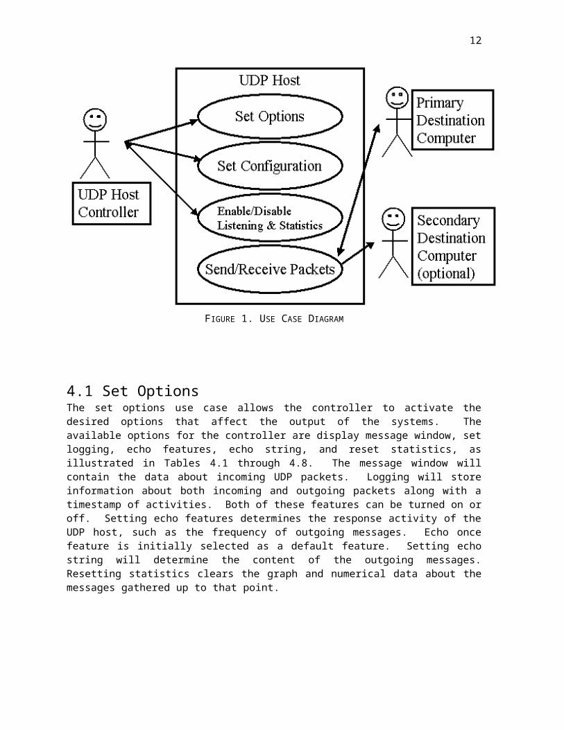
4 Use CasesTo understand the UDP host system, it is helpful to develop a set of use cases. Use cases are narrative descriptions of the sequence of events of an actor using the system. For example, in the following UDP host use case diagram (Figure 1), there are three actors who trigger or participate in the use cases. When the use case is triggered by an actor action, the system responds with corresponding system functions. Tables 4.1 through 4.17 gives a description of expanded use cases and the sequence of actor actions and system responses for each use case.
FIGURE 1. USE CASE DIAGRAM
4.1 Set OptionsThe set options use case allows the controller to activate the desired options that affect the output of the systems. The available options for the controller are display message window, set logging, echo features, echo string, and reset statistics, as illustrated in Tables 4.1 through 4.8. The message window will contain the data about incoming UDP packets. Logging will store information about both incoming and outgoing packets along with a timestamp of activities. Both of these features can be turned on or off. Setting echo features determines the response activity of the UDP host, such as the frequency of outgoing messages. Echo once feature is initially selected as a default feature. Setting echo string will determine the content of the outgoing messages. Resetting statistics clears the graph and numerical data about the messages gathered up to that point.
8

4.1.1 Set OptionsActor Action System Response1. UDP host controller sets options:
a. If Reset Statistics, see section Option Reset Statistics.
b. If Message Window, see section Option Message Window
c. If Logging, see section Option Logging
d. If Echo Feature, see section Option Echo Feature
e. If Echo String, see section Option Echo String
2. UDP Host changes the options on the system
3. UDP Host controller confirms the changes 4. UDP Host confirms the options set
TABLE 4.1 SET OPTIONS
4.1.2 Option Reset Statistics1. UDP host controller resets statistics 2. Clears statistics and runtime of the application.3. The controller may choose to continue setting other options. See 4.1.1 Set Options.
TABLE 4.2 RESET STATISTICS
4.1.3 Option Message Window1. UDP host controller sets Message Window to be ON/OFF
2. ON - Displaying up to last 50 messages received by the UDP host.OFF – Does not display current messages received by the UDP host.
3. The controller may choose to continue setting other options. See 4.1.1 Set Options.
TABLE 4.3 MESSAGE WINDOW
4.1.4 Option Logging1. UDP host controller sets Logging ON/OFF, and supplies a new log file
2. ON - Create file and write to file all inbound and outbound messages with a 10 milliseconds time stamp.OFF – Do not write any messages to the log file.
3. The controller may choose to continue setting other options. See 4.1.1 Set Options.
TABLE 4.4 LOGGING
Alternative Course: Line 2: Insufficient disk space or write error. Displays error message.
9

4.1.5 Option Echo Feature1. UDP host controller configures Echo Back. 2. Displays features for controller to choose from.3. Controller chooses one feature:
a. If Message Spiking, see Section: Message Spiking
b. If Time Based Activity, see Section: Time Based Activity
c. If Multicast, see Section: Multicastd. If Echo Once, continue to next part
4. Sets the chosen feature as the echoing traffic pattern.
5. The controller may choose to continue setting other options. See 4.1.1 Set Options.
TABLE 4.5 ECHO FEATURE
4.1.5.1 Message Spiking1. UDP host controller chooses Message Spiking
2. Ask user for the spike value
3. UDP host controller enters the spike value 4. Save spike value
TABLE 4.6 MESSAGE SPIKING
4.1.5.2 Time Based Activity1. UDP host controller chooses Time Based Activity
2. Asks controller to enter in time interval
3. Controller enters time interval in milliseconds
4. Saves time interval message
TABLE 4.7 TIME BASED ACTIVITY
4.1.5.3 Multicast1. UDP host controller chooses Multicast 2. Asks controller to enter in multicast address3. Controller enters multicast address 4. Saves the multicast address
TABLE 4.8 MULTICAST
4.1.6 Option Echo String1. UDP host controller chooses the message string type, and the appropriate parameter.
2. Save message string type, and the string.
3. The controller may choose to continue setting other options. See 4.1.1 Set Options.
TABLE 4.9 ECHO STRING
4.2 Set ConfigurationThis use case allows the controller to change configuration such as IP address (Table 4.2.2) and port number (4.2.3) through a graphical user interface. Being able to change this information will allow the UDP Host and the destination(s) to be dynamic.
10

4.2.1 Set ConfigurationActor Action System Response1. Controller selects configuration to set.
a. If IP address, see section IP address configuration.
b. If Ports, see section Port configuration.
2. UDP host sets to the entered configuration
3. UDP Host controller confirms the changes 4. UDP Host confirms the options set
TABLE 4.10 SET CONFIGURATION
4.2.2 IP address configuration1. UDP host controller chooses to configure IP address
2. Prompt the user the choices: Host IP address, Secondary IP address
3. UDP host controller picks the choice between Host IP address and Secondary IP address
4. Prompt the user the IP address
5. The controller enters IP address. 6. Verify IP address, and save IP address6. The controller may choose to continue setting other configurations. See 4.2.1 Set Configuration
TABLE 4.11 IP ADDRESS CONFIGURATION
Alternative Course: Line 6: If the IP address entered is not a valid IP address, display alert window “Invalid IP
address” and wait for the user to enter again.
4.2.3 Port configuration1. UDP host controller chooses to configure Port number.
2. Prompt the user the choices: Host IP address, Secondary IP address
3. UDP host controller picks the choice between Host IP address and Secondary IP address
4. Prompt the user the Port number
5. UDP host controller enters a Port number 5. Set the current host port number with the user-entered port number.
6. The controller may choose to continue setting other configurations. See 4.2.1 Set Configuration
TABLE 4.12 PORT CONFIGURATION
Alternative Course: Line 5: If the port number entered is not a valid port number, display alert window “Invalid
port number” and wait for the user to enter again.
11
4.3 Enable/Disable listening and statisticsThis use case allows the controller to put the UDP host in running or idle mode, which triggers packet listening on/off. Also various statistics about message activity are displayed to the user interface, as illustrated in Table 4.12
4.3.1 Enable/Disable listening and statistics1. UDP Host controller enables listening and statistics
2. Starts listening mode
3. Calculates new statistics and new graph every five seconds
4. Controller disables listening and statistics 5. Stop listening mode6. End statistical calculation and graphical display
TABLE 4.13 ENABLE/DISABLE LISTENING AND GENERATING STATISTICS
4.4 Send and Receive PacketsThis use case is the core function of the UDP host. It handles the incoming UDP messages, analyzes the UDP packets, generates specific UDP messages, and directs them to the appropriate destination.
4.4.1 Send and ReceiveActor Action System Response1. This use case begins when a Primary Destination Computer sends an UDP packet to the UDP Host.
2. The UDP Host analyzes the packet to retrieve the IP address and the port number of the Primary Destination Computer.3. The UDP Host updates the statistics of inbound traffic and total traffic.4. The data of the obtained UDP packet is written to the Message Window.5. The obtained UDP packet information is logged with a time-stamp to a file.6. Echo traffic to the Primary Destination Computer, and the Secondary Destination Computer:
a. If message spiking is selected, see section Echo Spiked Message.
b. If time based message is selected, see section Echo Time Based Message.
c. If multicast is selected, see section Echo Multicast.
d. If echo once is selected, see section Echo Once.
7. The UDP Host updates the statistics of outbound traffic and total traffic.8. All sent UDP packets information is logged with a time-stamp to a file.
9. The Primary Destination Computer receives packet(s) from the UDP Host.
TABLE 4.14 SEND AND RECEIVE PACKETS
12

Alternative Courses- Line 4: Option is set to not write the data of the obtained UDP packet to the Message
Window.- Line 5: Option is set to not log any packet information.- Line 6: Option is set to not echo any traffic.- Line 6: If Secondary Destination is selected, message will be targeted to the Secondary
Destination, and not Primary Destination.- Line 8: Option is set to not log any packet information.
The following 4 sub-use cases provide more detailed information about events for each echo feature. In the following sub-use cases, the term “appropriate destinations” refers the destination(s) mentioned in Line 6 of the Send and Receive Use Case (Table 4.13).
4.4.1.1 Echo Spike MessageActor Action System Response1. Primary Destination Computer sends an UDP packet to the UDP Host.
2. Buffer up messages until spike value is reached.
3. Send the buffered messages to the appropriate destinations.
4. The Primary Destination Computer receives packet(s) from the UDP Host.
TABLE 4.15 SPIKE MESSAGE
4.4.1.2 Echo Time Based MessageActor Action System Response1. Primary Destination Computer sends an UDP packet to the UDP Host.
2. Send a message to the appropriate destinations.
3. Sleep for a given interval.4. Repeat from 1.
5. The Primary Destination Computer receives packet(s) from the UDP Host.
TABLE 4.16 TIME BASED MESSAGE
4.4.1.3 Echo MulticastActor Action System Response1. Primary Destination Computer sends an UDP packet to the UDP Host.
2. Change the TTL (time to live) of the packet to an appropriate threshold.3. Echo the a message to the given multicast address.
4. Members of the multicast address receive packet(s) from the UDP Host.
TABLE 4.17 ECHO MULTICAST
13

4.4.1.4 Echo OnceActor Action System Response1. Primary Destination Computer sends an UDP packet to the UDP Host.
2. Echo the message back to destination computer.
3. The Primary Destination Computer receives packet(s) from the UDP Host.
TABLE 4.18 ECHO ONCE
4.5 Use Case RankUse cases are ranked to help define the sequence in which the various use cases are developed. High-ranking use cases need to be dealt with in early development cycles. Use cases that significantly influence the core architecture are ranked the highest.
4.5.1 Qualities Used to base rankThe following attributes form the criteria used to rank the importance of each of the use cases.
A – Significant impact on the architectural design, such as adding many classes to domain layer or requiring persistence services.
B – Include risky, time-critical, or complex functions.C – Involve significant research, or new and risky technology.D – Represent primary line-of-business processes.
Range: from 0 (low) to 5 (high) priority
4.5.2 Use Case ScoresUse Case A B C D TotalSet Options 4 2 3 3 12Set Configuration 2 2 2 2 6Enable/Disable Listening and Generating Statistics 4 5 4 4 17Send/Receive Packets 5 5 5 5 20
TABLE 4.19 USE CASE SCORES
4.5.3 Use Case ResultsRank Use Case JustificationHigh Send/Receive Packets
Enable/Disable Listening and Generating Statistics
Send/ receive packets is the main functional requirement of the UDP host and has a major impact on its design.Enable/disable listening and generating statistics begins listening for packets and displays graphical statistics.
Medium Set Options Set options includes significant functionality such as message statistics and logging.
Low Set Configuration Setting configuration involves setting up the networking between systems and isn’t difficult to develop.
TABLE 4.20 USE CASE RESULTS
14

5 Conceptual Diagram
The conceptual model in Figure 2 is a model of significant concepts, attributes, and associations in the problem domain. The model also provides information about relationships and multiplicity in the interactions between concepts. Creating the conceptual model helps to gain a better perspective through an object-oriented analysis of the problem domain.
FIGURE 2. CONCEPTUAL DIAGRAM MODEL OF THE UDP HOST
Note: If multicast feature is chosen, then the destination of the outgoing messages will be the multicast address group.
6 System Behavior
Before moving on to logical design, System Behavior needs to be analyzed to define how a system behaves. System Behavior is a description of what a system does, while hiding the actual implementation. For this document, collaboration diagrams are used to demonstrate the important system behaviors of the UDP Host.
6.1 Collaboration Diagrams
Collaboration Diagrams illustrate the interactions between objects in a graph format. Sections 6.1.1 through 6.1.4 detail some of the significant system behaviors with the help of collaboration diagrams.
15

6.1.1 Message Spiking
Figure 3 illustrates the Message Spiking Option. Message Spiking “buffers” messages until a configurable spike value is reached. The VB Winsock receiving a UDP packet causes the initial event. Upon receiving a UDP packet, the centralSystem object obtains three pieces of information from the Winsock object, which is located in the centralSystem: Source IP Address, port number and data. Then the centralSystem sends an event to the StatisticGenerator to count the number of incoming messages, and to the logGenerator if the logFlag is set true. The StatisticGenerator will update the inbound statistics, the logGenerator will log the incoming message, and the messageQueue will start storing messages until the spike value is reached. After the spike value is reached, the messageQueue will dequeue its messages. Each dequeued messages will notify the centralSystem to send an event to the statisticGenerator and the logGenerator to update the outbound statistics, and then each message will send itself to the appropriate destination.
FIGURE 3. COLLABORATION DIAGRAM FOR MESSAGE SPIKING OPTION
6.1.2 Enable listening and statistics
Figure 4 illustrates the collaboration diagram for Enable Listening. Enable Listening is when the UDP host puts the system into listening mode. The initial event begins when the user enables the system from the GUI, in which the GUI_IO_Handler sends an event to the centralSystem. Within the enable method in the centralSystem, a procedure is executed to bind the winsock to start listening for incoming messages. From there, the centralSystem sends events to start the statisticGenerator. The centralSystem also sends an event to itself to start the Timer object in the centralSystem. The Timer object will trigger statisticGenerator to display statistics on the GUI. The statisticGenerator waits until an event from the Timer is called, which occurs every 5 seconds.
16

FIGURE 4. COLLABORATION DIAGRAM FOR ENABLE LISTENING AND STATISTICS
6.1.3 Set Logging Option
In Figure 5, the Logging event begins when the user chooses to turn logging option on or off from the GUI. The GUI_IO_Handler will capture the event from GUI, and then send the event to the centralSystem to set logging flag accordingly. If the logging option is turned on, the centralSystem will start the logGenerator, otherwise, the logGenerator will be stopped.
FIGURE 5. COLLABORATION DIAGRAM FOR LOGGING
6.1.4 Time Based Activity
Figure 6 illustrates the collaboration diagram for Time Based Activity. The initial event is instigated the centralSystem receives a UDP message, and the Winsock network functions parse out the source
17

IP, port number, and data. The centralSystem will send an event to the statisticsGenerator to update and display the number of incoming messages. If the logFlag is set to true, centralSystem will also send an event to logGenerator to start logging to a predetermined file.
Afterwards, the centralSystem will create an instance of message object and enqueue it in the messageQueue. When the centralSystem sees that the current option is Time Based Activity, it will start the message timer (a VB built-in object) in the centralSystem. The timer will be generating an event at a predetermined time interval. At the specified time, the centralSystem will invoke an event in messageQueue to send all messages in the queue by calling the peekAndSend() function.
The peekAndSend() function sends all the messages in the queue without dequeuing, since every message must continue to be sent at every time interval. Finally, before each message is sent to destination, messages will notify the centralSystem to send an event to statisticsGenerator and logGenerator to update outbound statistics and log outbound messages respectively.
FIGURE 6. COLLABORATION DIAGRAM FOR TIME BASED ACTIVITY
6.2 System Operation Contracts
A contract is a documentation of what an operation is obligated to achieve. When a system operation is called, a System Operation Contract is written to describe each system operation’s behavior.
18

6.2.1 Contract for Enable/Disable Listening & Statistics Use Case
6.2.1.1 Contract for enableContract
Name: enable()Responsibilities: Puts the UDP host into running mode, which triggers on packet listening. Once enabled, statistics are also generated.Type: CentralSystemCross References: System Functions: R1.3
Use Cases: Enable/Disable Listening & StatisticsNotes:Exceptions:Output:Pre-conditions: System is currently in idle mode.Post-conditions:
CentralSystem.status was set to running (attribute modification). Winsock is bound to a port, and is listening for incoming messages. Statistics timer started. statGen started.
6.2.1.2 Contract for disableContract
Name: disable()
Responsibilities: Puts the UDP host into idle mode, which turns off packet listening. Once disabled, statistics generation will be stopped as well.Type: CentralSystemCross References: System Functions: R1.4
Use Cases: Enable/Disable Listening & StatisticsNotes:Exceptions:Output:Pre-conditions: System is currently in running mode.Post-conditions:
CentralSystem.status was set to idle (attribute modification). Winsock closed. Statistics timer stopped. statGen stopped.
19

6.2.2 Contract for the Send/Receive Packets Use Case6.2.2.1 Contract for sendMsg
ContractName: sendMsg()Responsibilities: Send message with its data, destination IP and destination port.Type: MessageCross References: Use Cases: Send/Receive PacketsNotes:Exceptions:Output:Pre-conditions: Instance of message has already been created.Post-conditions:
Outbound messages statistics updated.
6.2.2.2 Contract for sendAllContract
Name: sendAll(spike_val : integer)
Responsibilities: Send all messages in the Message Queue after the spike value is reached.Type: MsgQueueCross References: System Functions: R2.1
Use Cases: Send/Receive PacketsNotes:Exceptions:Output:Pre-conditions: Message Spiking option is on and spike value has been reached.Post-conditions:
MsgQueue is empty.
6.2.2.3 Contract for recvMsgContract
Name: receivedMessageInfo()
Responsibilities: Receive message from Primary Destination Computer. Winsock parses the message’s content to extract primary destination address and primary destination port.Type: centralSystemCross References: System Functions: R1.5, R2.1, R2.2, R2.3
Use Cases: Send/Receive PacketsNotes:Exceptions:Output:Pre-conditions: Primary Destination Computer sends out message.Post-conditions:
New message information stored in centralSystem. Statistics for incoming messages updated.
20

6.2.2.4 Contract for recvMsgInfo
ContractName: sentMessageInfo()
Responsibilities: Receive analyzed message from message. Type: centralSystemCross References: System Functions: R2.1, R2.2, R2.3
Use Cases: Send/Receive PacketsNotes:Exceptions:Output:Pre-conditions: Post-conditions:
Outbound message information stored by centralSystem. Outbound message logged.
7 ClassesClasses are the set of objects that share the same attributes, operations, methods, relationships, and semantics. A good software engineering technique requires an engineer to divide up the system responsibilities into smaller sub-responsibilities. This separation process is beneficial because as a result of this process, the system gains many positive qualities such as reusability, modularity, and encapsulation.
A reverse engineering technique from the GRASP controller patterns was used to define our classes. After determining all of the responsibilities of the system, we assigned a class to each of them so that each of the classes is in charge of certain responsibilities. The interaction diagrams and conceptual model that had been designed aided in generating the set of software classes. Some attributes were duplicated from the previous conceptual model, and additional attributes were added. Methods from interaction diagrams were added and modified to represent to the team’s system design.
In Figure 7, all the classes in the system are displayed. Along with their class names, all the attributes and the methods of each class are shown to demonstrate their design details.
21
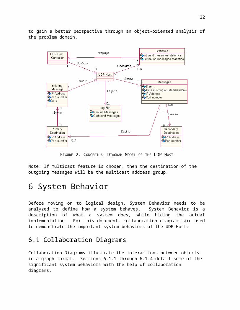
FIGURE 7. CLASS LIST OF THE UDP HOST
22

FIGURE 7. CLASS LIST OF THE UDP HOST (CONTINUED FROM PG. 23)
Each class has been assigned specific responsibilities of the systems. The separation of responsibilities were carefully considered and decided to ensure high cohesion and low coupling to the system. Here are the class responsibilities of each class.
centralSystem The responsibility that the centralSystem class has surpasses the responsibility of all the other classes, as it is the core of the UDP Host. There are two major responsibility involved with this class. The first responsibility of the centralSystem is that it “knows” things. This class is an expert of the system, and it contains vast amount of information. The information includes:
23

centralSystem(cont’d)
a) IP address of the UDP Hostb) Port number that the UDP Host bound toc) Status of the UDP Host (running, idle, etc)d) Feature that the system is running (message spiking, multicasting, etc)e) Outgoing stringf) Logging option ON/OFFg) Message window option ON/OFFh) Spike value (for message spiking feature)i) Time interval (for time based activity feature)
The second responsibility of the centralSystem is to reduce coupling in the system. The complexity of the UDP Host requires for many objects to interact with each other. In order to contain all the classes from selfishly talking to other classes and create high coupling in the system, the need for having a middleman arose. The centralSystem was nominated for this task since it already is the expert of the system, and it can easily make judgments on how the system should behave and who should be involved in certain behaviors.
GUI_IO_Handler The GUI_IO_Handler class behaves as the service class between the GUI and the centralSystem to filter input and output. All the statistics are handled by the statisticsGenerator, but the GUI_IO_Handler is responsible for all other I/O operations between the GUI and the centralSystem. Operations that this class handles are:
a) System commands from the GUI to the centralSystem (enable, disable, reset statistics)
b) Option setting input from the GUI to the centralSystemc) Configuration setting input from the GUI to the centralSystemd) System information display to the GUIe) Message Window display to the GUIf) Error checking on the input/output
logGenerator The logGenerator is a service layer class between the application layer and the storage layer that is responsible for creating log files and writing to those files. If the option is set to log messages, the centralSystem object passes all the incoming and outgoing messages to the logGenerator object, and the logGenerator writes message information to the specified files. The information logged differs between the two types, and each type has 5 parts.
Incoming UDP Message Type:a) Timestampb) Message = incoming messagec) Source IP addressd) Source port numbere) Data
Outgoing UDP Message Type:a) Timestampb) Message = outgoing messagec) Destination IP addressd) Destination port numbere) Data
message The message class represents the outbound message(s) created by the centralSystem. This class has destination information such as IP address and Port number, and also contains the message string to be sent to the destination. This class is responsible for sending itself to the appropriate destination, and notifying the centralSystem of when it is leaving.
24

messageQueue The messageQueue is a placeholder for newly generated outbound messages by the centralSystem. This class keeps the messages in the queue to buffer messages. Queuing messages is necessary for message spiking and time base activity options.
statisticsGenerator This class is responsible for keeping all the statistics, and displaying those statistics to the GUI. The attributes in this class are used to store all the statistics, and on event caused by the VB timer, this class will transmit those statistics to the GUI. The information that this class is responsible for are:
a) Total inbound message receivedb) Inbound message received per hourc) Total outbound message sentd) Outbound message sent per houre) Total messages handledf) Messages handled per hourg) System status (running, idle, etc)h) System running time
TABLE 7.1 DESCRIPTION OF CLASS RESPONSIBILITIES
The relationship between the classes is as follows:
When the system starts up, GUI_IO_Handler, centralSystem, statisticsGenerator, and messageQueue will be created. When the user puts the system into running mode (a mode in which the system will be able to listen to the inbound packets and echo various messages back), the centralSystem will start to accept incoming packets.
The centralSystem will control a VB timer for sending messages which will generate an event at every predetermined number of seconds. The event will trigger the statisticsGenerator to display all the statistics to GUI.
If the logging option is turned on, the centralSystem also creates a logGenerator, which is responsible for logging information of inbound and outbound packets. Upon arrival of inbound packets, the centralSystem will update the inbound statistics in the statisticsGenerator, pass on packets information to the logGenerator, and create an instance of the message class and enqueue created object(s) into the messageQueue.
If the default “echo once” feature option is turned on, a single message is sent out immediately. If the “time based activity” feature option is turned on, the centralSystem will use a VB timer to generate an event continuously based on the user-inputed time interval. When the event occurs, all the messages in the messageQueue will be sent out. When each message is sent out, the message will inform the centralSystem to update statistics and log information. This sequence will be done continuously until the user disables the UDP host system.
25

FIGURE 8. CLASS DIAGRAM OF UDP HOST
8 PackagingPackaging is an additional level of organization, which allows further development of system architecture layers. By grouping objects that interact most with each other into one package, there is less interfacing between packages. This process of analyzing the connections between objects and classes increases the cohesion and lowers the coupling that is involved between the presentation, application domain and logic, and storage layers.
8.1 Three Tier ArchitectureThe package diagram demonstrates elements into organized packages. Usually there are horizontal layers and vertical partitions to arrange the objects in the program. In Figure 9.1, there are threehorizontal layers, which are the following: Presentation, Application, and Storage. The presentation layer contains the GUI, which will be the interface between the user and the system's internal functions. The application layer consists of domain and service layer objects that execute the main
26

functions such as listening for packets and sending messages. Finally the storage layer keeps the log file separate from the remainder of the system.
FIGURE 9.1: THREE TIER ARCHITECTURE
8.2 Presentation Layer
The GUI in the presentation layer (Figure 9.2) is the area that will display the statistics in numerical and graphical format alongside a basic system summary. The StatisticsGenerator (Figure 9.5) interfaces directly with the GUI for performance reasons: statistics must be updated at most every five seconds and passing data through other classes would have a negative effect on this requirement.
Other parts of this interface will allow the user to change options and configure the UDP Host. It will let logging and message window to be enabled, features to be changed, and IP address and port to be set. It also triggers events that send updates to the centralSystem (Figure 9.1, 9.3) in the domain layer. This layer separates the location of user interaction with the system and its functions.
27

FIGURE 9.2: PRESENTATION LAYER
FIGURE 9.3: DOMAIN LAYER: SYSTEM CORE
8.3 Application Layer
The application layer is separated into an additional two: first, there are the System Core and Message Generator objects in the domain layer (Figures 9.3, 9.4). Then the service layer contains helper objects StatisticsGenerator (Figure 9.5), LogGenerator (Figure 9.6), and GUI_IO_Handler (Figure 9.7). These three objects will interface with the domain layer to assist in calculating statistics, logging to files, and handling input/output to and from the GUI as façade controller respectively.
The System Core holds the centralSystem that will use the Winsock library to unwrap UDP messages and parse its information. It also does all message handling for all incoming messages both of which must be saved to the log file in the storage layer.
The Message Generator will use a Message Queue to handle all outgoing messages, which must also be saved to the log file through the Log Generator. All of these messages must also be counted and then all resulting statistics computed by the statisticsGenerator will be displayed and graphed in the presentation layer. This layer distinguishes itself from the other layers by doing the main calculation and message handling that is vital to this program.
28

FIGURE 9.4: DOMAIN LAYER: MESSAGE GENERATOR
FIGURE 9.5: SERVICE LAYER: STATISTICS
FIGURE 9.6: SERVICE LAYER: LOG
29

FIGURE 9.7: SERVICE LAYER: INPUT/OUTPUT HANDLER
8.4 Storage Layer
The storage layer encloses the log file (Figure 9.1) whose content will include timestamp, incoming or outgoing status, IP, and port. Additionally, if it is an incoming UDP message, its data will be saved as well. There will be a window that allows the user to select a new or pre-existing file to log to. This layer divides the storage capabilities that this program requires from the remainder of the system.
9 Administrative InformationThis section details the assignment distribution to all members. This includes VB tutorials that were assigned and general responsibilities.
Tasks MemberNetworking Nobo, Huan ChangGUI/Graphics/Calculations SirinyaEvent Handling Keung Sik, Hui AiTime/File I/O Mary
TABLE 9.1 VB TUTORIAL ASSIGNMENTS
Tasks MemberCollaboration Diagrams for Set Options, Set Configuration, Startup, Shut down; Class diagram
Mary
Fix requirements document, system operation contracts Hui AiClass descriptions SirinyaCollaboration Diagrams for Time based and Message Spiking, Class diagram
Keung Sik
System operating constracts Huan ChangDescription of class history, collaboration diagram for time based activity diagram
Nobo
TABLE 9.2 DESIGN 0.8 ASSIGNMENTS
30

Tasks MemberWebpage SirinyaMeeting minutes Everybody
TABLE 9.3 GENERAL RESPONSIBILITIES
10 Problems, Conflicts, and ResolutionThe team has encountered various challenges in managing a large software project like the Motorola
UDP project, which is the first large one for most of the team members. For instance, when deciding
how to implement the logging of UDP message activity, the team had to decide which format to use.
When team members asked the Motorola sponsor if XML was preferred, he replied that plain text
would be fine. The first small obstacle had been hurdled.
Another major issue of discussion among team members was developing a system design that best
incorporates low coupling and high cohesion between all classes and objects. Many ideas were
suggested, and differing ideas were presented. One suggestion was to let each object that required
logging interact and pass their information to logGenerator. This design resulted in high cohesion but
also high coupling. Many parameters need to be passed from object to object since multiple objects
need the same data obtained in a previous step. Another idea is to use the centralSystem as the go-
between which would accept and send all the required information used in logging. This would also
result in high coupling, which is also undesired. The team also considered using a global variable
that flags whether log is turned on or off. One benefit of this approach is that all classes would have
easy access to the variable. The general consensus among members was that using global variables is
not a good idea in an object-oriented program because it violates encapsulation principles. As a result
of the discussions, the conclusion was to add methods to several different classes. This would reduce
the load on a particular object by spreading it across multiple objects. This also avoided creating
more objects, which would complicate all the diagrams and increase complexity.
A programming language barrier also had to be hurdled. All members had little or no experience
with the Visual Basic language. This inexperience presented some early problems when moving
from the design phase to the implementation phase. In the design document version 0.8, the initial
design of the UDP Host system contained 9 classes. During the design revisions in the creation of
document version 0.9, members gained more experience with VB and learned that inheritance is a
complicated and formidable task in VB, especially in the built-in existing Winsock and timer classes.
After discussion, the team decided that changing the system design to account for these changes was
31

easier than researching the language to fit the current design. For this reason, 3 classes from the
system were removed and more functionality was added to the central system. This design problem
was due to the lack of experience that the team members had with the VB language. Although a good
conceptual design of the system had been developed, the initial design needed to be adapted as the
team members gained a better understanding of VB programming.
On a communication level, there is a great deal of magic needed to find free time between six seniors.
In addition to schoolwork, team members are involved with work, travel, interviews, and teaching, in
which each demands large amounts of time in one’s schedule. Everybody also lives in a different part
of campus, and this must be considered when finding meeting times and places. The best method of
communication has been email through an alias set up at lore and additionally, a journal was set up at
http://expert.cc.purdue.edu/~nobushig/cgi-bin/display_journal.cgi to take special note of work that is
done away from group meetings in preparation for the next meetings. Extra work beyond what is
assigned at group meetings may be written in the journal so that it can be noticed better.
32

11 GlossaryActiveXA set of integration technologies which enables software components to interoperate in a networked environment using any language.
COM/DCOMDistributed Component Object Model is a protocol that enables software components to communicate directly over a network in a reliable, secure, and efficient manner for use across multiple network transports. It is based on the Open Software Foundation's DCE-RPC.
IP AddressA 32-bit address assigned to a computer that uses TCP/IP protocols. The sender must know the IP address of the destination computer before sending a packet.
MulticastingMulticasting is a form of addressing in which a set of computers is assigned one address. A copy of any datagram sent to the address is delivered to each of the computers in the set. Often used for audio or video conferences.
OLEObject Linking and Embedding is a stream of programming functions that allowed programmers to create applications for users that allowed one large document to consist of a variety of smaller document, each created in a different application.
PortA logical connection place in TCP/IP where a client program specifies a particular server program on a computer in a network that range from 0 to 65536, with 0 to 1024 usually reserved for use by certain privileged services. TTLTime to Live is a field in the Internet Protocol that specifies how many more hops a packet can travel before being discarded or returned.
UDPUser Datagram Protocol is a TCP/IP protocol that provides application programs with connectionless communication service.
WinsockWindows Sockets is a standard network API co-developed by PC network industry leaders including Microsoft, Novell, Hewlett-Packard, and FTP Software.
XMLExtensible Markup Language is a markup language that provides a more structured medium than HTML, allowing us to define new document types and style sheets, as needed providing methods to add well-defined markup to electronic documents.
33