Requirements management and MOD closure process …784025/FULLTEXT01.pdf · Requirements management...
47
Requirements management and MOD closure process study on the A330 WV80 project Master thesis report LAUZIER, Charles-Antoine AIRBUS Superviser: BONNEFOUS, Jean-François ENSICA Supervisor : SHEA, Joseph KTH Supervisor : RINGERTZ, Ulf 13/03/2014
Transcript of Requirements management and MOD closure process …784025/FULLTEXT01.pdf · Requirements management...

Requirements management and MOD closure process study on the
A330 WV80 project
Master thesis report
LAUZIER, Charles-Antoine
AIRBUS Superviser: BONNEFOUS, Jean-François
ENSICA Supervisor : SHEA, Joseph KTH Supervisor : RINGERTZ, Ulf
13/03/2014

Page 1
GLOSSARY
AAR Allocated Aircraft Requirements
EASA European Aviation Safety Agency (UE)
EIS Entry Into Service
FAA Federal Aviation Administration
FAL Final Assembly Line
GPP Generic Project Process
KPI Key Performance indicator
LBIP Lifecycle for Business Improvement Projects
MG Maturity Gate
MOD Modification
MSN Manufacturing Serial Number
MTOW – MLW – MZFW Max Take-Off Weight – Max Landing Weight – Max Zero Fuel Weight
OBS – PBS – WBS Organizational Breakdown Structure – Product Breakdown Structure – Work Breakdown Structure
P&P Project and Processes
PDP Product Development Process
PMO Project Management Officer
RISE RE-use, Improve and Share Experience
TLAR – TLIR – TLPPR Top Level Aircraft Requirements – Top Level Industrial Requirements – Top Level Project & Process Requirements
TPO – TPR Top Project Objectives – Top Project Requirements
WP Work Package
WV Weight Variant

Page 2
ACKNOWLEDGEMENTS
First and foremost I would like to express my thanks to Airbus for enabling me to complete my
aerospace engineering degree within the Long Range Program Development department.
I would like to take this opportunity to express my profound gratitude and deep regards to my
tutor, Mr. Jean-François Bonnefous (Project Leader of the A330 Weight Variant 80), for his
exemplary guidance, monitoring and constant encouragement throughout the course of this
master’s thesis. The help and guidance and regular feedback given by him time after time shall
carry me a long way in the journey of life on which I am about to embark.
I also would like to thank Mr. Yannick Couderc, Mr. Jean-Marc Graindorge and Mr. Frédéric
Maréchal, members of the central project team and colleagues as well as Mrs. Odile Jubecourt, head
of the BLD department, and Mr. Vicent Lebas, technical leader of the A330 Weight Variant 80
project, who created an enjoyable working environment with their patience and openness and who
helped me in completing this task through various stages.
I would like to thank all the people that worked in the module 37 of the B06 building for their
welcome and the support they have given me throughout the completion of my project.
Finally, I would like to thank my academic tutor for ascertaining the proper conduct of this master’s
thesis.

Page 3
Table of Contents
GLOSSARY 1
ACKNOWLEDGEMENTS 2
1. INTRODUCTION 6
1.1 THE COMPANY 6
1.2 THE BLD DEPARTMENT 6
2. CONTEXT OF THE PROJECT 7
2.1 OBJECTIVES AND SCOPE OF THE NEW VARIANT AIRCRAFT 7
2.2 THE PROJECT MANAGEMENT METHOD AT AIRBUS 8
2.2.1 The Project Development Process (PDP) 8
2.2.2 The Weight Variant 80 project management strategy 10
3. REQUIREMENTS MANAGEMENT IN THE PRE-MG7 PROJECT GOVERNANCE 14
3.1 THE ISSUE OF REQUIREMENTS MANAGEMENT 14
3.2 REQUIREMENTS BUILD-UP WITHIN THE WV80 PROJECT 15
3.3 MG7 PREPARATION 17
3.3.1 The Verification and Validation (V&V) process 17
3.3.2 The bottom-up consolidation 18
4. GOVERNANCE IMPROVEMENTS IMPLEMENTATION 20
4.1 STRATEGY AFTER MG7 20
4.1.1 Lessons Learnt 20
4.1.2 Requirements cleaning and database creation 20
4.1.3 Reqtify mock-up implementation 22
4.2 VISUAL MANAGEMENT IMPLEMENTATION 24
4.2.1 Purpose of visual management 25
4.2.2 Deployment for the Weight Variant 80 project 25

Page 4
5. MOD CLOSURE PROCESS INVESTIGATION 27
5.1 CONFIGURATION MANAGEMENT 27
5.1.1 General presentation 27
5.1.2 The Full Change process 28
5.2 MOD CLOSURE PROCESS INVESTIGATION 30
5.2.1 Link with the PDP 30
5.2.2 MOD certification 30
5.2.3 MOD closure planning 31
5.2.4 Comparison with a serial flow MOD 34
6. CONCLUSION 35
7. MASTER’S THESIS FEEDBACK 36
8. BIBLIOGRAPHY 37
ANNEX 1: DETAILED PRESENTATION OF AIRBUS 38
ANNEX 1.1 SOME HISTORY: FROM ARBEITSGEMEINSCHAFT AIRBUS AND SUD-AVIATION TO AIRBUS 38
ANNEX 1.2 AIRBUS TODAY 38
ANNEX 1.2.1 The A320 family 39
ANNEX 1.2.2 The Long Range family 40
ANNEX 1.2.3 The A380 41
ANNEX 2: PRESENTATION OF THE A330 42

Page 5
Table of Figures
Figure 1: Hierarchical organization breakdown .............................................................................. 6 Figure 2: A330 market coverage evolution .................................................................................... 7 Figure 3: A330 continuous improvement........................................................................................ 8 Figure 4: The PDP key phases and Maturity Gates ....................................................................... 9 Figure 5: Link between the xBS .................................................................................................... 10 Figure 6: A330 WV80 - Master schedule ..................................................................................... 12 Figure 7: A330 WV80 project - Work Breakdown Structure (WBS)............................................. 13 Figure 8: A330 WV80 Requirements cascade and verification process ..................................... 16 Figure 9: V&V process .................................................................................................................. 17 Figure 10: V&V bottom-up activities ............................................................................................. 18 Figure 11: Non-compliance summary by document .................................................................... 19 Figure 12: Non-compliance risk evaluation .................................................................................. 19 Figure 13: Requirement identification and general attributes ...................................................... 20 Figure 14: Requirement verification attributes ............................................................................. 20 Figure 15: Database view ............................................................................................................. 21 Figure 16: KPI for the TPR coverage ........................................................................................... 22 Figure 17: Reqtify configuration window ...................................................................................... 23 Figure 18: Main view of Reqtify .................................................................................................... 23 Figure 19: Reqtify impact analysis................................................................................................ 24 Figure 20: Drawing of the meeting room with the visual management boards ........................... 26 Figure 21: A330 WV80 MOD breakdown ..................................................................................... 27 Figure 22: Change process pre and post MG5 ............................................................................ 28 Figure 23: Full change process .................................................................................................... 29 Figure 24: Link between the full change process and the PDP ................................................... 30 Figure 25: A330 WV80 MOD list .................................................................................................. 31 Figure 26: A330 WV80 MOD criticality ......................................................................................... 31 Figure 27: MOD closure process .................................................................................................. 32 Figure 28: Technical documents release schedule ...................................................................... 33 Figure 29: Comparison between a serial flow and a A330 WV80 MOD ...................................... 34 Figure 30: Cockpit commonality (A320 on the left - A330 on the right) ....................................... 39 Figure 31: A320 Sharklet .............................................................................................................. 39 Figure 32: A340 in flight Figure 33: A330-200 in flight .......................................................... 40 Figure 34: A350 key characteristics ............................................................................................. 40 Figure 35: A350 first flight ............................................................................................................. 41 Figure 36: A380 ............................................................................................................................ 41 Figure 37: ETOPS route explicative scheme ............................................................................... 42 Figure 38: ETOPS flight between LHR and JFK .......................................................................... 42 Figure 39: A330 manufacturing sharing ....................................................................................... 43 Figure 40: A330 Key characteristics ............................................................................................. 45 Figure 41: A330 Main drawing ...................................................................................................... 46

Page 6
1. INTRODUCTION
1.1 THE COMPANY
The civilian aerospace division of the newly renamed AIRBUS Group (previously EADS), Airbus is the world’s leading commercial aircraft manufacturer. Its market shares represent more than half of the total aircraft orders of all airlines in the world. With the A300, which was its very first plane built in 1972; Airbus now builds 4 types of aircraft: the A320 family, the A330, the A380 and the A350 whose entry into service is planned for the end of 2014. A detailed presentation of the company is given in Annex 1.
1.2 THE BLD DEPARTMENT
Everyone working at Airbus has a siglum corresponding to his job. This makes it easier to know what someone’s function is. A siglum is composed of several letters, referencing an activity. There are 24 main domains at Airbus, such as:
H: Human resources F: Finance C: Customers B: Programmes
M: Airbus military E: Engineering P: Procurement D: Production
Each of the above main domains is subdivided in sub-activities which are defined by letters, and so on. As an example, I was BLD. This means that I was working for the Development (D) of the Long-range (L) Programme (B). The Figure 1 below is an extract of the organigram, focusing on my position breakdown.
Figure 1: Hierarchical organization breakdown

Page 7
2. CONTEXT OF THE PROJECT
2.1 OBJECTIVES AND SCOPE OF THE NEW VARIANT AIRCRAFT
The Airbus A330 is a wide-body twin engine jet liner whose first flight was on November 2, 1992. With an initial maximum take-off weight (MTOW) of 212 tons, in 2007 the A330 was modified into the weight variant 50 in order to increase this latter up to 235 tons. This is the current standard version of the aircraft, called “enhanced”.
Market forecasts have shown that the use of both the A330 and the A350 represents a good combination for airlines. However, they desired an increase of the A330 range with an identical payload to operate new routes. It is within this context that the Weight Variant 80 project was launched during the end of 2011, with the aim of increasing the maximum take-off weight (MTOW) to 242 tons and a scheduled entry into service (EIS) in May 2015. The Top Requirements of the project to meet these needs consist in:
- Increasing the range by 500 NM - Increasing the payload by 7 tons for the same range
Finally, compared to the very first aircraft manufactured, the range will then have been increased by 52% which will allow it to cover a bit more than 90% of the global market, as shown in Figure 2.
Figure 2: A330 market coverage evolution
Page 8
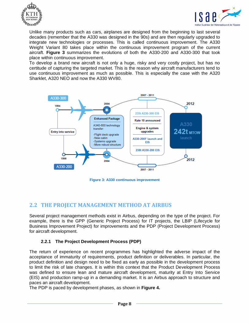
Unlike many products such as cars, airplanes are designed from the beginning to last several decades (remember that the A330 was designed in the 90s) and are then regularly upgraded to integrate new technologies or processes. This is called continuous improvement. The A330 Weight Variant 80 takes place within the continuous improvement program of the current aircraft. Figure 3 summarizes the evolutions of both the A330-200 and A330-300 that took place within continuous improvement. To develop a brand new aircraft is not only a huge, risky and very costly project, but has no certitude of capturing the targeted market. This is the reason why aircraft manufacturers tend to use continuous improvement as much as possible. This is especially the case with the A320 Sharklet, A320 NEO and now the A330 WV80.
Figure 3: A330 continuous improvement
2.2 THE PROJECT MANAGEMENT METHOD AT AIRBUS
Several project management methods exist in Airbus, depending on the type of the project. For example, there is the GPP (Generic Project Process) for IT projects, the LBIP (Lifecycle for Business Improvement Project) for improvements and the PDP (Project Development Process) for aircraft development.
2.2.1 The Project Development Process (PDP)
The return of experience on recent programmes has highlighted the adverse impact of the acceptance of immaturity of requirements, product definition or deliverables. In particular, the product definition and design need to be fixed as early as possible in the development process to limit the risk of late changes. It is within this context that the Product Development Process was defined to ensure lean and mature aircraft development, maturity at Entry Into Service (EIS) and production ramp-up in a demanding market. It is an Airbus approach to structure and paces an aircraft development. The PDP is paced by development phases, as shown in Figure 4.

Page 9
Figure 4: The PDP key phases and Maturity Gates
The Maturity Gate (MG) reviews are key enablers to secure the maturity of the PDP implementation. They are defined to enable an efficient assessment of the Aircraft Development Process progress and maturity. This assessment, which is GO/NO-GO, enables better key decision in taking as well as identification of risks against target requirements. The table below summarizes the main topic of each MG review. In case of the development of a new variant aircraft, as it is the case for the A330 WV80, only odd review are done.
MG1 Scenarii analysis MG9 Ready for S1 FAL MG2 Scenarii selection MG10 Ready for S1 power on
MG3 Entry into concept MG11 Ready for first flight – End of S1 qualification
MG4 Industrial launch MG12 Start of serial A/C (S2) production
MG5 End of concept MG13 Entry into service – End of S2 qualification
MG6 Start of development A/C (S1) production
MG14 Start of serial A/C ramp up (S3) production
MG7 End of design MG15 End of S3 qualification
MG8 Ready for assembly and tests MG16 Full rate production

Page 10
The PDP relies on several breakdown structures in order to manage the diversity of the involved disciplines:
PBS: The Product Breakdown Structure is a 4-layer hierarchical decomposition
of the aircraft product. The PBS is a key input for the Work Breakdown Structure (WBS)
WBS: The Work Breakdown Structure is an organized view of the activities to be
specified, deployed, verified and delivered by the program in order to fulfill the program requirements and business case.
OBS: The Organization Breakdown Structure is an organized view of the
program teams. Each work package has to be allocated to an OBS team or a supplier.
The PBS is the first breakdown to be determined as it defines how the final aircraft will be. Due to the close links between the WBS and project organization, it is strongly recommended that the WBS and OBS are developed in parallel. The WBS of the A330 WV80 project is presented in the next section, in Figure 7. The links between the work packages and the breakdown structures are shown in Figure 5.
Figure 5: Link between the xBS
2.2.2 The Weight Variant 80 project management strategy
The A330 Weight Variant 80 is a relatively small project compared to the development of a new aircraft and as a result the processes and tools deployed fit the project scale. However, the concepts presented such as Maturity Gate reviews and breakdown structures are at the heart of the project governance. A reference document, called the Management Plan defines the perimeter and process for A330 WV80 project management. Every project has such a document in order to precisely define and inform how governance will be done. In particular, it defines meeting frequency which will occur

Page 11
in addition to those planned by the PDP. A set of three major types of meetings have been set up in order to structure the project progression and as part of the central project team, I was in charge of the minutes:
A monthly meeting which involves all the work package leaders is mandatory. The aim of this meeting is not only to update a status of the project progression but also to interact with the other actors. An exhaustive report with major risks, key achievements, planning, and milestones synchronization with the related work packages is required.
A weekly meeting has the aim of giving an updated status about the week’s progress. At the beginning, a standardized report with the key achievements, issues, supports required and next steps was asked for. However, after a feedback from the WPs, it was then decided to change the project governance and ask for such a report only every other week. As a result, its aim is to:
Share information and make people talk with other work package leaders to discuss about major issues.
Get central project support in case of blocking points such as procurement for example.
A weekly PMO (Project Management Officer) reporting was set up. Involving only the central project team, this meeting focuses on project management issues for the coming week.
My internship took place at the interface of the end of the “Design” and the beginning of the “Integration & Qualification” phases, as shown in the project master schedule presented in Figure 6. I arrived soon after the MG5 review during which the baseline was advanced by two months and was then involved in the MG7 preparation. I was involved in the central project team as shown in the WBS of Figure 7.

Page 12
Figure 6: A330 WV80 - Master schedule
The MG7 review is the end of design. It means that all the technical solutions have been found and that their development is finished. From this milestone, parts are manufactured and tests can be performed. As a result, MG7 is at the bottom of the V-cycle which makes this milestone a key-stone of the project. Before MG7 it is the development phase - descending part of the V - and after it is the verification part - ascending part of the V – with the project closure in sight.
I have been given two main missions and an additional one. First of all, I was in charge of requirements management, both in preparation for MG7 and for the following reviews, for which I performed a cleaning of the existing documents and created a consolidated database. The second main mission was to investigate the MOD closure process. To understand this process will help closing the project. Indeed, MG7 correspond to the bottom of the development V-cycle. The manufacturing parts will start to be produced and their compliance to requirements has to be checked. On the other hand, it is the starting point of project closure. Eventually, the last mission given was to create and deploy a visual management tool, which will be used by either the team or the top management. This report aims at presenting these tasks.
In addition, I was involved in general project management monitoring, such as managing the access to the project folders or making sure that there was always enough space to store documents. The project documents are stored both in a collaborative workspace called iShare whose storage capacity is limited, and in a specific folder on the Airbus intranet called SFS. As few people have access to the SFS, the iShare is the tool that teams mostly use. These storage bases reaching saturation, I regularly identified items that could be removed or relocated to always have enough free space. One of the solutions to free up space is to replace documents by links to the company archives.

Page 13
Fig
ure
7:
A330 W
V80 p
roje
ct
- W
ork
Bre
akd
ow
n S
tru
ctu
re (
WB
S)
Team I joined

Page 14
3. REQUIREMENTS MANAGEMENT IN THE PRE-MG7 PROJECT GOVERNANCE
3.1 THE ISSUE OF REQUIREMENTS MANAGEMENT
Requirements management is present across many sectors, whether industrial, economic or even political. Indeed this is due to that fact that a requirement may be not only a function but also a concept. Requirements management and functional analysis are often compared. However this is a mistake as the basic elements of functional analysis are functions. Moreover, the leading suppliers of requirements management software, such as DOORS®, do not make the link between these two activities. The largest users of requirements management demanding sectors are industries with complex products for which the development takes several years, such as aeronautics or weaponry. Within the framework of developing a new aircraft, requirements represent a means of communication deriving from the needs in order to describe future aircraft capabilities. They must be precisely defined and are known as a baseline for product development. As a result, any change occurring to this baseline will most likely result in additional costs and delays whose impact increases with time. Requirements are usually classified into three categories:
Functional requirements: They describe system characteristics or processes
that the system must execute. One finds in this category the work rules and the functional requirements for security (confidentiality, etc). They correspond to the functional analysis main functions and services.
Non-functional requirements: They describe the properties that the system
must have, such as technical requirements of IT security (confidentiality, integrity), performance, and availability according to the defined criteria. They correspond to the constraints functions of functional analysis.
Constraints: They are in a certain way the limits of the development. It could be
to define an operating system with which the system should work, or what coding language to use in order to set the system. These kinds of requirements correspond to constraint functions of functional analysis.
The customer-supplier agreement is based on requirements as they create a contractual context with a common language. They allow the delivery of products in line with users’ expectations while removing many communication problems. Their assets are diverse:
To attest product conformity with respect to constraints
To know the project status
To define and manage tests
To limit interpretation and subjectivity
To follow the evolution of changes. Only product and performance issues are really linked to customer needs. However, manufacturing and processes are also important as they represent company know-how and will lead to the final success of the project. Moreover, one should remember that aircraft projects are dynamic and therefore requirements evolve while the project is running.

Page 15
Within the scope of a project such the A330 WV80, aircraft requirements cover the following contents:
- What the plane should look like - What it should be capable of (functions, performances) - How it should be manufactured, assembled and tested - How the development and manufacturing phases are managed (processes)
3.2 REQUIREMENTS BUILD-UP WITHIN THE WV80 PROJECT
A hierarchy exists among requirements; indeed, all of them do not have the same status or importance. Starting with only a few main ones, others will little by little appear as one goes to a lower level as it is explained below. A requirement can be broken up into sub-requirements. This is called the requirements cascade. It is theoretically possible to have as many sub-requirements as needed, however it is recommended not to fall into exhaustiveness. This cascade ensures traceability from top levels down to part levels and sub-contractors. The highest level document is the Top Project Requirements (TPR). It is the conversion of external requirements coming from customers into internal requirements. As a result, involving the customers as early as possible in the requirements definition not only contributes to significantly reduce development cycles and rework, but it is also a way to ensure that the requirements issued from the customers are complete, consistent and understandable by the aircraft manufacturer. The TPR is considered as an agreement document as mentioned above. Created by the technical leader, it is approved by the program leader – the long range program leader in this case. The second step for requirement management is to translate the TPR into a more workable basis which consists in top level requirements. These specify the TPR and are grouped into specific topics. The top level requirements are composed of:
Top Level Aircraft Requirements (TLAR): this document gathers product and
performance requirements. It is written by the technical leader.
Top Level Industrial Requirements (TLIR): this document concerns industrial, manufacturing and testing requirements. It is written by the industrial manager.
Top Level Process and Project Requirements (TLPPR): this document deals with processes, project management, quality, procurement requirements. It is written by the Head of the PMO long range.
Finally, engineering teams cascade top level requirements documents to work packages and suppliers so that they can access those which are relevant for them. During this cascade process, requirements can be reworded in order to better fit individual components. In the A330 Weight Variant 80 project, industrial requirements were managed at the central level and not properly cascaded. During this overall process, all requirements are studied and challenged one-by-one to check that they are relevant. When a cascade is performed from an upper level, the stakeholder is the owner of the upper level requirement. It can happen that work packages decide to add requirements, either for themselves, or for other work packages with whom they have inter-dependencies. It this case, they are not managed at the project level but directly by the work packages who added them.

Page 16
At the end of the cascade process, each requirement is referenced and has the following attributes:
An identifier
An owner and stakeholder
A version
A means of verification and validation
A status about its compliance with the appropriate evidence
Acceptance or rejection from the stakeholder
As requirements build-up is done at the very beginning of a project, I was not involved in this process; However, to understand how it is done is important to perform the validation & verification (V&V) activity. The A330 WV80 cascade is represented in Figure 8. I inherited of this cascade and had to get familiar with it. The following paragraph explains how it is used for the verification and validation process.
Figure 8: A330 WV80 Requirements cascade and verification process

Page 17
3.3 MG7 PREPARATION
3.3.1 The Verification and Validation (V&V) process
As part of the preparation for MG7, I was in charge of the requirements verification and validation (V&V). A status about requirement coverage was asked and presented. Indeed, as this milestone is at the interface between the end of design and start of the industrialization a clear test plan for all the products had to be defined. In Figure 8, the V&V matrices are represented in orange. The blue part gathers Product Requirements. These have a direct impact on the product design. This is the reason why both the design and the product itself are checked during the verification process. The design is reviewed during Critical Design Reviews (CDR) so that non-compliances can be detected as early as possible. The grey box represents the Industrial requirements, also called the Enabling Products as they concern the manufacturing part (industrial set-up, testing support and tools, etc.). As mentioned earlier, there is no official cascade for the work packages in this project; however they contribute to the verification matrix. Finally, the Project and Processes are represented by the green part. These requirements deal only with the project governance and focus in particular about planning, quality, procurement and project management. They are cascaded to all the work-packages according to the WBS presented in Figure 7.
For the verification of all these requirements, a V&V matrix to monitor the Verification and Validation actions is associated to each document, as shown in orange in Figure 8. As requirements give key information about project advancement, a status of V&V activities is performed during Maturity Gate (MG) reviews. This ensures that proper verification is done at each step of the development process. Figure 9 is a graphical representation of the Verification & Validation process.
Figure 9: V&V process

Page 18
At Airbus, there are 10 different families of means of verification, used for every kind of requirement:
MVV0 – Compliance Statement / Engineering judgment MVV1 – Review MVV2 – Calculation / Analysis MVV3 – Safety Assessment MVV4 – Tests on bench / Prototyping / Mock-up MVV5 – Ground tests on A/C MVV6 – Flight Tests MVV7 – Inspection by airworthiness authorities or mandated person MVV8 – Simulation / Modeling MVV9 – Equipment qualification MVV10 – Manufacturing / Support verification
3.3.2 The bottom-up consolidation
Considering the reasonable size of the project, the Central Project Team uses a tailored approach of the standard process. For example, DOORS®, the standard requirement management software, was not deployed and only Excel files are used. Indeed, the modifications integrated on the current A330 resulted in only several hundred requirements compared to around 50000 for the A350 or the A380. From the requirements cascade, the V&V activities are performed with the WPs who had to indicated their means of verification. I monitored this process using key performance indicators (KPIs) I created. They helped me to easily know the status of each step of the verification and validation and also the requirements acceptance by the stakeholders for each work package. Finally, a couple sessions had been organized with the central project team in order to consolidate the results for documents of a higher level: TLAR and TLPPR first and then TPR. The bottom-up process is shown in Figure 10.
Figure 10: V&V bottom-up activities

Page 19
During these sessions, all the requirements are reviewed one by one, going from the low level (work packages) to the highest (TPR) ensuring that higher level requirements were properly verified using the lower ones. Several non-compliance appear for both the TLAR and TPR, as summarized in Figure 11.
TLAR TPR
Total nummber 66 24
Passed 28 12
Planned 36 12
Figure 11: Non-compliance summary by document
These non-compliances were studied in order to evaluate their risks and their status was presented at MG7. As shown in Figure 12, it turned out that most of them had a low or very low risk and only one was critical.
TLAR TPR
NIL 27 5
Very Low 7 6
Low 1 -
High 1 1
Figure 12: Non-compliance risk evaluation
In spite of these non-compliances, the MG7 was passed green. It was however mentioned that the product verification had to be completed within the end of February. The non-compliances were well understood by the MG7 review panel members. Following this review, some lessons learnt were put into practice and will be explained in the next part.

Page 20
4. GOVERNANCE IMPROVEMENTS IMPLEMENTATION
4.1 STRATEGY AFTER MG7
4.1.1 Lessons Learnt
Lessons Learnt is a standard practice in project management. It enables everyone involved within the project to record what has worked well and what on the contrary was critical, in order to help and better future projects. It is used throughout the project, during the preparation of the MG reviews and a summary session is organized at the closure of the project. For example, the A320 Sharklet project was closed in 2013 and we attended their lesson learnt session to anticipate the issues that we might face and even avoid them. Airbus puts the emphasize on sharing this return of experience and a dedicated tool (RISE – Re-use, Improve and Share Experience) has been set up. So far, the main lessons learnt from the A330 WV80 project are:
Start the verification and validation process at the very beginning of project otherwise it is difficult to catch up with the work load.
Better cascade and challenge requirements to avoid having irrelevant ones. Not all of them have to be cascaded.
4.1.2 Requirements cleaning and database creation
Several meetings with the chief engineer were organized in order to challenge each requirement about their relevance and check the cascade sequence. Also, it is decided to perform a V&V activity at every milestone and not one time only as it was done before. This enabled us to be sure no unexpected changes occurred and if so they were challenged to comply with the initial requirements. First all V&V matrices are created, gathering both the P&P and product requirements, for every work package. The attributes for a requirement identification, shown in Figure 13, were kept unchanged while the ones for the verification presented in Figure 14, were reviewed for
standardization and more coherence. The latter attributes are identical for both P&P and product requirements.
Figure 13: Requirement identification and general attributes
Figure 14: Requirement verification attributes
Assigned Requirement ID
Assigned Requirement Statement AR version
AR Stakeholder
AR Owner
Allocated Req ID
AO-3-001 The A330 WV8x Variants development shall be made with the same
suppliers as for the current A330 programme. V1 JM. Graindorge N.
Rullier PPR-005
P&PR ASSIGNED REQUIREMENTS

Page 21
After creating these V&V matrices and updating the top level documents, a consolidated database in Excel summarizing the entire cascade sequence is set up ; Figure 15 gives an
overview of it. The aim of this file is to gather and record information from low level matrices so that each upper level requirement can be reviewed relying on this low level information. For example, to validate a specific TLAR, one can see at the same time all the corresponding cascaded AAR. This is particularly useful for top level documents validating together with validation monitoring. As a result, the database brings more visibility, more clarity and an ease of use in monitoring the requirements status and acceptance from a project level.
Figure 15: Database view
The line highlighted in grey corresponds to a higher level requirement. It means that the verification action can be performed only when all the above requirements have reviewed. The process is the same for even higher requirements: TPRs can be reviews only when corresponding TLAR and/or TLPPR – TLIR have been first reviewed. For each requirements, the V&V attributes previously presented have been created. In order to keep an historic of what have been done and the previous status, both MG7, MG9 and MG13 were implemented. In addition to this database, some KPI (key performance indicator) are built up in order to monitor the verification and validation status of each requirement document (TPR, TLAR and TLPPR) and the coverage by lower levels of each top requirement. This will help to quickly spot the blocking points. The following Figure 16 is the KPI for TPR coverage. It is organized in a table whose first line
gives an overview of the document coverage and each line below corresponds to a specific requirement status. There is no value in this table as the V&V activity was not performed yet for MG9 and MG13 when this report was written.
ID Statement Owner ID Statement Owner ID Statement WBS
TPR001Modifications shall be designed to increase A330-300 range by
at least 350 nm.V. Lebas TLAR005
(A330-300)
The following Weight variants shall be offered :
- WV80 : MTOW 238 t / MLW 187 t / MZFW 175 t
- WV81 : MTOW 242 t / MLW 187 t / MZFW 171 t
- WV82 : Dynamic Payload between WV80 and WV81
The WV8X Variants shall be offered as options in the catalog.
AAR-001The fuselage shall be designed and certified with the A330-300 loads as
defined in document G010RP1318947 issue 3 A330 WV8x fuselage loadFUSELAGE
TPR001Modifications shall be designed to increase A330-300 range by
at least 350 nm.V. Lebas TLAR005
(A330-300)
The following Weight variants shall be offered :
- WV80 : MTOW 238 t / MLW 187 t / MZFW 175 t
- WV81 : MTOW 242 t / MLW 187 t / MZFW 171 t
- WV82 : Dynamic Payload between WV80 and WV81
The WV8X Variants shall be offered as options in the catalog.
AAR-002The wings shall be designed and certified with the A330-300 loads as defined
in document A330 WV8X G010RP1325626 issue 1WING
TPR001Modifications shall be designed to increase A330-300 range by
at least 350 nm.V. Lebas TLAR005
(A330-300)
The following Weight variants shall be offered :
- WV80 : MTOW 238 t / MLW 187 t / MZFW 175 t
- WV81 : MTOW 242 t / MLW 187 t / MZFW 171 t
- WV82 : Dynamic Payload between WV80 and WV81
The WV8X Variants shall be offered as options in the catalog.
AAR-003FCPC and FMGEC Weight Tables shall cover the weight range of A330-300
WV80/81/82SYSTEMS
TPR001Modifications shall be designed to increase A330-300 range by
at least 350 nm.V. Lebas TLAR005
(A330-300)
The following Weight variants shall be offered :
- WV80 : MTOW 238 t / MLW 187 t / MZFW 175 t
- WV81 : MTOW 242 t / MLW 187 t / MZFW 171 t
- WV82 : Dynamic Payload between WV80 and WV81
The WV8X Variants shall be offered as options in the catalog.
AAR-004
The landing gear shall be designed and certified with the A330-300 loads as
defined in document:
- A330-200/300 WV080/081 Wheel & Tyre Loads for Nose and Main Landing
Gears - G010RP1325940 - 2.0
- A330-200/300 WV080/081 Static Loads for Enhanced Main Landing Gear
Design - G010RP1323411 - 1.0
- A330-300 WV081 - Main Landing Gear (MLG) Fatigue Ground Loads for MRW
Mission - G010RP1325692 - 1.0
LG
TPR001Modifications shall be designed to increase A330-300 range by
at least 350 nm.V. Lebas TLAR005
(A330-300)
The following Weight variants shall be offered :
- WV80 : MTOW 238 t / MLW 187 t / MZFW 175 t
- WV81 : MTOW 242 t / MLW 187 t / MZFW 171 t
- WV82 : Dynamic Payload between WV80 and WV81
The WV8X Variants shall be offered as options in the catalog.
AAR-005
RFE, pylons and nacelle shall be certified with the A330-300 loads as defined
in document G010RP1325626 issue 1 A330 WV8x loads synthesis normal
conditions
AO
TPR001Modifications shall be designed to increase A330-300 range by
at least 350 nm.V. Lebas TLAR005
(A330-300)
The following Weight variants shall be offered :
- WV80 : MTOW 238 t / MLW 187 t / MZFW 175 t
- WV81 : MTOW 242 t / MLW 187 t / MZFW 171 t
- WV82 : Dynamic Payload between WV80 and WV81
The WV8X Variants shall be offered as options in the catalog.
PROJECT
Source: TPR TLAR - TLIR - TLPPR AAR - PPR

Page 22
Figure 16: KPI for the TPR coverage
4.1.3 Reqtify mock-up implementation
REQTIFYTM is a requirements traceability and impact analysis software package. It creates links between documents coming from a huge range of different sources (such as DORRS®, Excel, etc) and then enables the user to easily follow the requirement cascade. It also automatically generates reports. Initially developed by IBM®, as an add-on to its Rhapsody® software (known as the Gateway Add On), Reqtify is now a Dassault System product. This is currently used by the IT department of Airbus in requirements management. In order to have an easier way to visualize requirements coverage, a mock-up using a snapshot of the MG7 situation without including the TLIR has been implemented. The main challenge was to understand the syntax to parameter the software. Indeed, there was no user’s guide clearly explaining how to code the filter used for analyzing Excel file input. Figure 17 gives an overview of the configuration window. On the left side, on can remark several menus; the most important ones are “Types” – to define the different types of document analysis- and “Filters” – to create filters-. It has to be pointed out that a different type of analysis had to be create for each document to ensure the links between them and requirements identifiers were correctly taken
TPR coverage
Cascaded
count
Coverage
count
Coverage
%
Cascaded
count
Coverage
count
Coverage
%
TPR 23 0 0 23 0 0
TPR001 7 0 0 7 0 0
TPR002 3 0 0 3 0 0
TPR003 1 0 0 1 0 0
TPR004 3 0 0 3 0 0
TPR005 7 0 0 7 0 0
TPR006 3 0 0 3 0 0
TPR007 3 0 0 3 0 0
TPR008 3 0 0 3 0 0
TPR009 2 0 0 2 0 0
TPR010 1 0 0 1 0 0
TPR011 2 0 0 2 0 0
TPR013 1 0 0 1 0 0
TPR014 1 0 0 1 0 0
TPR020 2 0 0 2 0 0
TPR021 2 0 0 2 0 0
TPR022 1 0 0 1 0 0
TPR023 1 0 0 1 0 0
TPR024 1 0 0 1 0 0
TPR025 8 0 0 8 0 0
TPR026 1 0 0 1 0 0
TPR030 2 0 0 2 0 0
TPR031 2 0 0 2 0 0
TPR032 3 0 0 3 0 0
MG 13MG 9

Page 23
into account. The method used was then trial and error to see how the software behaved given some code elements.
Figure 17: Reqtify configuration window
Figure 18 shows the software main view. This view displays all the documents taken into account and the links between them. Furthermore, it gives a quick and visual overview of the percentage coverage using colors.
Figure 18: Main view of Reqtify
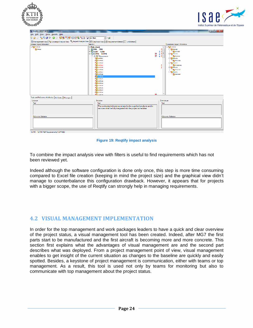
The next step in the mock-up build-up was to define filters on the stakeholder’s acceptance status. Being able to sort out requirements according to the stakeholder’s acceptance is one of the main useful characteristics. A second one is the impact analysis. It enables users to visualize the cascade both upward and downward starting from a selected requirement. This view is presented in Figure 19.
Page 24
Figure 19: Reqtify impact analysis
To combine the impact analysis view with filters is useful to find requirements which has not been reviewed yet. Indeed although the software configuration is done only once, this step is more time consuming compared to Excel file creation (keeping in mind the project size) and the graphical view didn’t manage to counterbalance this configuration drawback. However, it appears that for projects with a bigger scope, the use of Reqtify can strongly help in managing requirements.
4.2 VISUAL MANAGEMENT IMPLEMENTATION
In order for the top management and work packages leaders to have a quick and clear overview of the project status, a visual management tool has been created. Indeed, after MG7 the first parts start to be manufactured and the first aircraft is becoming more and more concrete. This section first explains what the advantages of visual management are and the second part describes what was deployed. From a project management point of view, visual management enables to get insight of the current situation as changes to the baseline are quickly and easily spotted. Besides, a keystone of project management is communication, either with teams or top management. As a result, this tool is used not only by teams for monitoring but also to communicate with top management about the project status.

Page 25
4.2.1 Purpose of visual management
Visual management can be described as "management by eyes". In other words, our eyes are used to help manage things, being able to see at a glance if the project is on track or not. It is a system that highlights abnormal conditions. When something goes wrong, there should be some way to see it right away. Another important aspect of visual management is that it helps provide clarity and transparence of information. In order to increase clarity and efficiency, information is communicated using visual signals and/or graphs instead of text and written instructions. Everyone involved in the process is in a better position to help if things go wrong because everyone can see what needs to be done. As a result, the purpose of visual management is to quickly communicate indicators on the project status to empower team members and enable them to better control it. The baseline of visual management is the normal state. The aim is to quickly see a deviation from that standard. An example can be a seating chart in school: the teacher can look over the classroom and see in an instant who is absent. Without assigned seating, the teacher would be forced to spend extra time each morning figuring out who is present and who is not. With the seating chart, the information is available in a fraction of second just by glancing around the room.
4.2.2 Deployment for the Weight Variant 80 project
Several loops were necessary to set-up the information and indicators that will be displayed. This step is the most important one in visual management set-up as it will influence how this tool will be used. For the Weight Variant 80 project, the first goal is to use it as a communication tool with the top management, giving them a quick and reliable overview of the project status. It will be used during weekly and monthly meetings to share information with all the work package leaders. However, as the room where the information is displayed is in public access the question of confidentiality was raised. What information is considered as sensitive? Is it relevant to show it? How can we keep confidentiality while showing it? After realizing a one-scale mock up, a meeting was organized and each indicator was challenged to quantify its relevancy and confidentiality. At the end, it was decided to remove the values and just keep the graph shapes. This way, the trend is visible while keeping the key values protected. The final version relies on three white boards, divided into five parts:
A general overview combined with the objectives. This board is mostly dedicated to the top management as well as to newcomers in orders to quickly become familiar with the project scope and status.
An EVM (Earn Value Monitoring) and Risks & Opportunity board. The global EVM as well as that of every work package is displayed. It shows the deliverable milestones as well as actual cost situation compared to the baseline. The second part of this panel is dedicated to risk and opportunities at the project level. With history kept in the folders, it aims at monitoring the risk criticality.
A resources and actions tracking board. Here again the board is divided into two parts. The resources are in fact the number of persons working on the project for each topic. It enables to monitor if each activity has the required workforce.

Page 26
At each meeting, actions are recorded. This is especially true during MG reviews and these actions have to be closed before the next review. This part of the board will enable the project team to ensure everything is done in time.
A couple trials and presentations to the project leader were necessary to come up with this solution. The initial implementation was based on 4 boards with in particular one dedicated to the earn value management (EVM), which was then removed and summarized for a better readability. This sequence also enabled selecting the information and KPI that would have been relevant to present. A drawing of the visual management board in the chosen room is presented in Figure 21. It will
be updated on a monthly basis by the next intern or the central PMO. All the material for visual management had been ordered and received however the installation couldn’t be completed due to a last minute administrative issue.
Figure 20: Drawing of the meeting room with the visual management boards

Page 27
5. MOD CLOSURE PROCESS INVESTIGATION
5.1 CONFIGURATION MANAGEMENT
5.1.1 General presentation
The main objective of configuration management is to define the physical baseline characteristics of a product, to control changes to this baseline, to record and report change processing and implementation, and to verify the product’s compliance with the applicable baseline. Commercial aircrafts, which consist in millions of parts, are built taking into account specification coming from both the aircraft manufacturer and airline which can be grouped in:
standard definition of the aircraft options from the manufacturer catalog specific requests of the customer – called GES –
As a result, an aircraft consists in a stack of MODs:
Type certificate MOD: it is the standard version of the aircraft Additional standard MOD: It is the product evolution, initiated by the aircraft
manufacturer, due to technology changes or in service problem solving Standard options: Those options are available on the manufacturer catalogue Customer version MOD: These are special requests from the customer
However, modifications can be embodied on the aircraft only if they passed through the entire change process and have been certified. Figure 21 shows how modifications are stacked to
form the Weight Variant 80 aircraft.
Figure 21: A330 WV80 MOD breakdown

Page 28
5.1.2 The Full Change process
The change process controls all product definition changes from initialization to implementation. It allows the project to identify a change, evaluate and investigate its impact, make the decision to implement and ensure that all tasks have been finished to close and approve the modification (MOD). As shown in Figure 22, the change process relies on two processes depending on the project development lifecycle: the change note process between MG3 and MG5 and the full change process after MG5. The change note process is a fast, light and flexible process. It is used to control baseline modifications in terms of scenario and not specifying MSN. One can notice that the 4 phases of the change – which are on the left column in orange in Figure 22 - correspond to the change note status (from opened to closed). On the other hand, the full change process is more complete and is the one used for serial flow aircraft. The aim of my second mission was to study if and how it is possible to transfer the MOD management from the project team to the serial flow in order close the project earlier.
Figure 22: Change process pre and post MG5
The full change process is divided into 4 steps with 3 Decision Gates (DG) between them, as shown in Figure 23. Almost all functions are involved in this process (engineering, finance,
manufacturing, etc.) as repercussions of all kind and not only technical are studied.

Page 29
Figure 23: Full change process
Each phase has a specific focus, with inputs, outputs and accountable persons:
Initialization: The objective of the Initialization phase is to register a complete
and clearly understood request, in a common format and with a common set of information, whatever the origin of the request.
Input: Request for change Output: Change Request
Evaluation: The objective of the Evaluation phase is to supply a rough estimation on the potential solutions to the request (in terms of technical, industrial, costing aspects).
Input: Change Request Output: Evaluation Sheet
Investigation: The objective of the Investigation phase is to describe the impacts of the Change regarding in detail (technical, industrial, costing… aspects), in order to prepare the decision for the MOD action (opening, inclusion…).
Input: Evaluation sheet Output:
Implementation: 1- Update repercussion sheets 2- Elaboration of MOD approval documents for authorities 3- Manage the MOD milestones & closure
Input: TRS, ERS, PRS Output: MOD, Technical Dossier (TD), Modification Approval Sheet (MAS)

Page 30
Each of the 3 decision gates aims at check specific aspect and maturity of the change and are chaired by the Configuration Control Board (CCB):
DG1: It checks the maturity of the change request and decides whether it is
worth launching the MOD. DG2: It confirms the MOD breakdown. DG3: It is during this review that the decision to open the MOD is made.
The full change process – which is applied from MG5 – is complete process with inputs and outputs at every phase. Besides, this process has several attributes whose most important are:
The applicability: it is defines the aircraft list for which the modification will be implemented.
The point of embodiment: it is the first aircraft for which the change will be applied. This is a strategic decision with is taken during DG2 and confirmed at DG3.
5.2 MOD CLOSURE PROCESS INVESTIGATION
5.2.1 Link with the PDP
The first step was to understand how to link the change process with the PDP used for the development. The parallel between these two is shown in Figure 24. As a result, most of the
MODs are today officially opened and are in the implementation phase. A clear plan leading to their certification is then built-up by the configuration management work package.
Figure 24: Link between the full change process and the PDP
5.2.2 MOD certification
MOD certification is a key step in MOD closure at it formalizes the fact that the MOD is closed and can be embodied on the aircraft. Modifications are defined as either minor or major depending on the effect they have on the aircraft in terms of criticality with regards airworthiness regulation. The MOD criticality is defined by the airworthiness authorities. It means that this qualification is made from a certification perspective. It is an important decision as a minor MOD can be certified by the aircraft

Page 31
manufacturer by the DOA (Design Organization Approval) privilege, while a major one has to follow a much more complex process involving the authorities.
A minor MOD is “a modification that has no appreciable effect on mass,
balance, structural strength, reliability, operational characteristics, noise, fuel venting, exhaust emission or other characteristics affecting the airworthiness of the product”. It means that no additional work is required to show compliance with the applicable certification basis.
A major MOD embeds all other type of modification and is classified as significant or not significant
Significant: the latest certification basis has to be considered Not significant: the certification basis originally used for the current
aircraft is applicable. The A330 Weight Variant 80 is composed of either several additional standard MOD or few option MODs (such as the WCT for example). Figure 25 is a table summarizing the different MODs of the WV80 and if they are standard or optional and Figure 26 shows each MOD criticality – one can realize that most modifications are major non-significant –.
WP NEW WV8X certification
Package A Package B WCT
Component WV8X S
lat 1
FT
F
FM
GE
C
Je
ttiso
n
Win
g
Fo
rwa
rd
fuse
lag
e
FC
PC
LG
stru
ctu
re
LG
syste
ms
Am
end
men
t
10
2
Dry
to w
et
ST
8
FC
MC
Figure 25: A330 WV80 MOD list
Figure 26: A330 WV80 MOD criticality
5.2.3 MOD closure planning
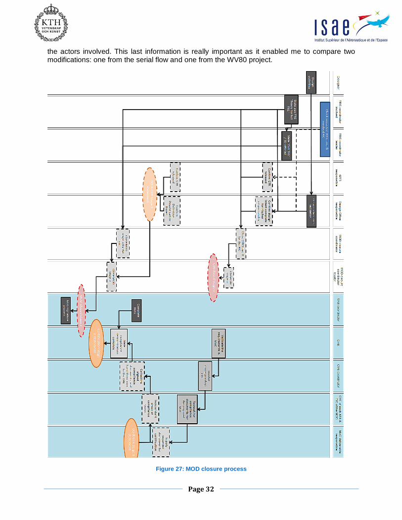
Using configuration management reference documents, I was able to draw the MOD closure process – presented on Figure 27 – and the technical documents planning – presented on Figure 28 –, from creation to validation. These schedules not only show the processes but also
Page 32
the actors involved. This last information is really important as it enabled me to compare two modifications: one from the serial flow and one from the WV80 project.
Figure 27: MOD closure process

Page 33
Figure 28: Technical documents release schedule

Page 34
5.2.4 Comparison with a serial flow MOD
Modifications for serial aircraft do not have a dedicated project to manage their progression. As a result, two questions are raised: what are the differences between these serial modifications and the ones in development projects such as the A330 WV80 and is it possible to transfer the WV80 modification to the serial flow. A governance transfer will enable closing the A330 WV80 project earlier. To investigate this topic, I decided to select two modifications concerning the fuselage: one modification of the WV80 – from the WCT – and one from the serial flow – opened after a problem that occurred in service –. I investigated who was in charge for each phase and key document to be delivered of the process. In service MOD A330 WV80 MOD
Change Request
Initiated by
Requestor
L.52.000114-0001
FIC LR FAL
ESBSI1
L.92.000253-001
FIC LR NCF
-
Evaluation sheet No Evaluation sheet in
ICC (tool for managing
change documents)
Closed by LR NCF
Leader
TRS signatures
Design Office
Air Worthiness
CM checker
HO Engineering
HO Config. Mgnt
TRS Issue 1 signed
ESBTD1
EIAASG
-
BLERS
BLERM2
TRS issue 1
-
-
ESBSI12
BLENY
BLMM1
MOD approval Not yet approved – no
MAS
Not yet approved – no
MAS
MOD COORDINATOR ESBSI11 EYYWA
Figure 29: Comparison between a serial flow and a A330 WV80 MOD
The table presented in Figure 29 summarizes the information found for the two selected MOD. I
noticed that the same department were in charge of the same tasks for both serial and aircraft development modifications. At a first glance, a governance transfer seems to be possible however, more information is need. I didn’t have time to complete this study which will be taken over by the next intern. In order to share what I have found so far, I wrote a small guide, a presentation and drawn the different process I am aware. These material will the basis for the study follow-up.
Page 35
6. CONCLUSION
As mentioned in the introduction, I had three missions during this master's thesis (requirements management, study of the MOD closure process for the A330 project WV80) and set up a visual management tool. After managing the requirements verification and validation for MG7 review, a redesign of these requirements has been achieved. Indeed, several of them were redundant and the links between the various documents were not always relevant. I also created a database to make the validation of documents from the top level easier. This database is used during reviews with requirements' stakeholders because it provides an overall view of the situation. Due to the size of the project , only Excel files were used. However, studies have been launched on the opportunity to use other methods. I implemented in particular MG7 situation in Reqtify to measure the suitability of such software. finally, we concluded that despite the visual tools, the ratio time spent and complexity versus added value was not high enough for this project size. A study using the DOORS software is also ongoing. As the software in still in the configuration loop, no results are known yet. MG7 is at the bottom of the V cycle and the end of the project begins to be in sight. Indeed, this review represents the end of the design and symbolizes the beginning of parts manufacturing . As a result, I studied configuration management and more particularly the modification (MOD) closure process and the possibility to transfer modifications management to the serial flow. Indeed, changes are also initiated in the series and not just developing projects. Since modifications made in the serial flow do not have dedicated projects, transferring the A330 WV80 modifications management would allow closing the project earlier. To answer the second question, I compared two modifications: one following a problem occurred in service (thus serial flow) and the other from the WV80 project. I discovered that the same actors were involved in both cases. Despite understanding the processes for the preparation of documents leading to certification (which i drew into a planning), this question is still open and further investigation will be performed by the next intern. Indeed, two sub-questions are still unanswered : who decides if a modification is considered as part of the serial flow or part of development and how to perform the transfer. The MOD closure process is linked to requirements management. Indeed, when a MOD is certified (and as a result closed), the corresponding requirements are met and all the V&V activities had been successfully performed.

Page 36
7. MASTER’S THESIS FEEDBACK
This master's thesis is the conclusion of my practical training at ISAE-formation ENSICA and my master in aerospace at KTH (Sweden). I had the opportunity to integrate the A330 programme management department, which has raised awareness and given me the basis of project management. Working with the Weight Variant 80 team was particularly rich and rewarding. I was able to not only work on the development aspect of a new aircraft, but also because of the project human scale brush against all functions involved and not a small part of them as it is the case for much larger projects. In addition, during this internship I faced issues related to human and I have developed communication skills. This master's thesis highlighted the versatility and multidisciplinarity of an aerospace engineer. Technical concepts learned in school helped me integrate myself and quickly understand issues and problems ; versatility has allowed me to learn new methods of working.

Page 37
8. BIBLIOGRAPHY
[1] Airbus internal website – Airbus people - http://airbuspeople.airbus.corp/
[2] Airbus external website – http://www.airbus.com/
[3] Airbus Photograph Gallery – https://airbus-photolib.keepeek.com/
[4] Project Management at AIRBUS – PM Guidebook Issue 1 – Hans Henrich ALTFELD, Head of Airbus Centre of Competence Project & Programme Management (CoC P&M)
[5] Product Development Process (PDP) booklet – Francis Charton, Luc Delaire, Lionel Marcouire, Daniel Neiss, Céline Polin – EZDI
[6] Project Management – Monitoring and Control – Airbus Means and methods AM2453
[7] CASE France – La gestion d’exigences pour les débutants - http://www.case-france.com
[8] Aircraft Configuration Management Rules (ACMR) – Airbus directive A1080
[9] Manage full change process – Airbus procedure AP2843.3
[10] A330 WV80 Configuration management plan – A330 WV80 Project reference document LR00PL1240343
[11] Wikipedia – Airbus presentation - http://fr.wikipedia.org/wiki/Airbus
[12] A330-300 Standard specification Issue 7.4 – Airbus aircraft specifications
[13] Wikipedia – A330 presentation - http://fr.wikipedia.org/wiki/Airbus_A330
Page 38
ANNEX 1: DETAILED PRESENTATION OF AIRBUS
ANNEX 1.1 SOME HISTORY: FROM ARBEITSGEMEINSCHAFT AIRBUS AND SUD-AVIATION TO AIRBUS
After the Second World War, the aeronautics industry was widely dominated by the US. Some projects did exist in Europe, but none of them really were successful. In 1966 the English, French and German governments decided to unite themselves and created a national company. Airbus was then born as a European consortium, which enables to share the developing costs. Among the different existing projects, the HBN-100 (for Hawker, Breguet and Nord) is selected and will become the Airbus A300. This aircraft aimed at carrying 300 passengers over more than 800 nautical miles. Realizing this aircraft was oversized for the market, the A330B was launched in 1969 at the Paris Air Show. It is the first wide body twinjet, capable of carrying 226 passengers in a comfortable two-class layout. An elongated 250-seat version, the A300B2, requested by Air France, was later produced in series. Five years later, the certification is granted and Airbus gets 10% of the market shares. The following years are darker for the company, until the US airline Eastern Airlines buys four A300B4. This order represents a decisive turning point for the company, which will subsequently experience a growing success. In 1979, Airbus more than doubled its market share reaching 26% in value! In 1978, the A310 which is a shorter version of the A300 is launched. After the English left then came back and entry of Spain, Airbus was composed of 4 national companies:
France : Airbus Operation SAS
UK: Airbus Operation Ltd.
Germany: Airbus Operation GmbH
Spain : Airbus Operation SL
Each of them takes care of manufacturing certain aircraft parts, before all parts are gathered by boat, truck and through the air with the Belugas, to Toulouse or Hamburg for final assembly. This work sharing is still in use today. It is only in 2001 that all the national entities are merged into a unique company: EADS (European Aeronautic Defense and Space Company), which became the Airbus Group in 2013.
ANNEX 1.2 AIRBUS TODAY
Since its inception, Airbus puts the emphasis on commonality between aircraft families. Indeed it makes training, maintenance and operation easier and cheaper. This led to the creation of the “Cross-crew Qualification”. It gives the possibility for pilots to switch aircraft family via difference training instead of full type rating training. For example, “the transition training from A320 Family aircraft to the A380 takes 13 working days, from A330/A340 Family aircraft it takes 12 working days, while a pilot with no Airbus FBW experience requires 24 working days to complete the A380 standard type rating course” (from airbus.com). The following two pictures – Figure 30 – represent the cockpit of an A320 (on the left) and an A330 (on the right). Only a few differences are visible.

Page 39
Figure 30: Cockpit commonality (A320 on the left - A330 on the right)
ANNEX 1.2.1 The A320 family
The A320 family includes the A318, A319, A320 and A321. They are medium-haul single-aisle aircrafts and the final assembly lines are located either in Toulouse, France or in Hamburg, Germany. The first plane of the family is the A320. Initially launched in 1984 and with a first flight in 1987, it pioneered the use of digital fly-by-wire flight control systems, as well as side-stick controls, in commercial aircraft. It was then extended to the A321, A319 and A318, changing only the length and passenger capacity. In 2010, Airbus officially launched the new generation of the A320 family with the A320neo, for "New Engine Option". New engines combined with airframe improvements and the addition of winglets, named Sharklets by Airbus, will deliver fuel savings of up to 15%. The standard versions of the A320 are called CEO for “Current Engine Option”. The A320 is the Airbus best seller with more than 5895 deliveries!
Figure 31: A320 Sharklet

Page 40
ANNEX 1.2.2 The Long Range family
The long range family is composed of the A330 (twin engine) and the A340 (four engines). A detailed presentation of the A330 is available in the Annex 2. Those two aircrafts are very similar as the A330 is based on the A340. Besides, they benefit from innovations coming from the single-aisle aircrafts, including adopting the fly-by-wire principle, mini-stick technology and glass-cockpit displays (EFIS). The A340 has four versions (-200, -300, -500, -600) depending on the length and then the passenger capacity. On the other side, the A330 is available in three versions (-200, -300 and -200F for the freighter). The A330-200 which is shorter but has a better range, is the long-range aircrafts best seller.
Figure 32: A340 in flight Figure 33: A330-200 in flight
Officially launched in 2005, the A350XWB for “Extra Wide Body” is made of 53% of lightweight structures (carbon fiber-reinforced polymer). It can carry 250 to 350 passengers in a typical three-class seating layout, or a maximum of 440 to 550 passengers in a single economic class, depending on variant. Key characteristic are presented in Figure 34. The A350 MSN001 first flew in Toulouse-Blagnac on June 14th 2013.
Figure 34: A350 key characteristics

Page 41
Figure 35: A350 first flight
ANNEX 1.2.3 The A380
The A380 is a four engines wide body full double deck aircraft. It is the world largest commercial jetliner. Unlike the Boeing 747, the A380 upper deck runs all along the fuselage. The A3XX project was launched in the 90s but the A380 first flight was only in 2005! Its dimensions are impressive: 80 meters wingspan, MTOW of 575 tons. It can carry between 525 and 853 passengers depending on the cabin configuration over 15700 km. This aircraft is the Airbus technological flagship.
Figure 36: A380

Page 42
ANNEX 2: PRESENTATION OF THE A330
With the apparition of wide-body aircrafts such as the Airbus A300 or the Boeing 767, that have high reliability and high power reserve in case of failure, ETOPS (Extended-range Twin-engine Operation Performance Standards) flights were allowed from 1985. ETOPS is a regulation from the International Civil Aviation Organization (ICAO) that allows twin-engines commercial aircrafts to use air routes with sectors to over than 60 minutes from an alternate airport. The following Figure 37 is a scheme of an ETOPS route.
Figure 37: ETOPS route explicative scheme
There are four types of ETOPS certificates:
ETOPS-90
ETOPS-120: it is granted to the airline after one years of trouble-free ETOPS-90
ETOPS-180: it is granted to the airline after one years of trouble-free ETOPS-120. This makes 95% of the Earth’s surface available to ETOPS flights.
ETOPS-240: The A330 was the first aircraft certified ETOPS-240, in 2009. The picture below is a concrete example of the advantage of ETOPS route for a flight between London Heathrow and New-York John-F.-Kennedy.
Figure 38: ETOPS flight between LHR and JFK
Page 43
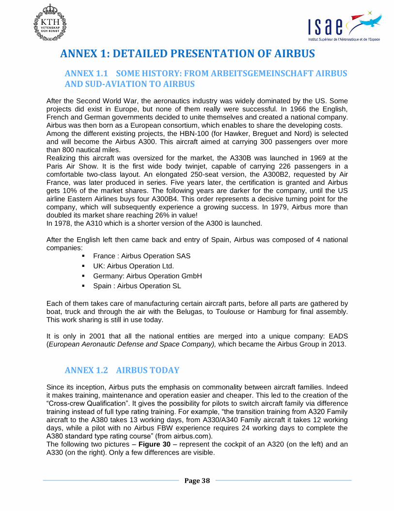
Airbus has decided to develop both a twin-engine jet (A330) and a four-engine (A340). Indeed, for the European aircraft manufacturer twin-engine lose their benefits against four engines from 11.000km (machine weight, fuel taken, engine power ...). The principle of commonality between aircrafts applies perfectly to the A330/A340 Programme. The A300 / A310 fuselage section and the modern avionics of the A320 are included in the A330. The only differences between the A330 and A340 are at the wing level and the fuel system. Commonality between aircrafts is not only an advantage in the design, but it also allows companies to save on training pilots and maintenance personal. In June 1987 the program is officially launched at the Paris Air Show. The first customers are Air Inter, Malaysia Airlines and Thai Airways International. The first flight took place on 14 December 1992. Besides, as the previous planes and as it is still done today, the A330 parts are built by all the different Airbus sites, as presented on Figure 39.
Figure 39: A330 manufacturing sharing
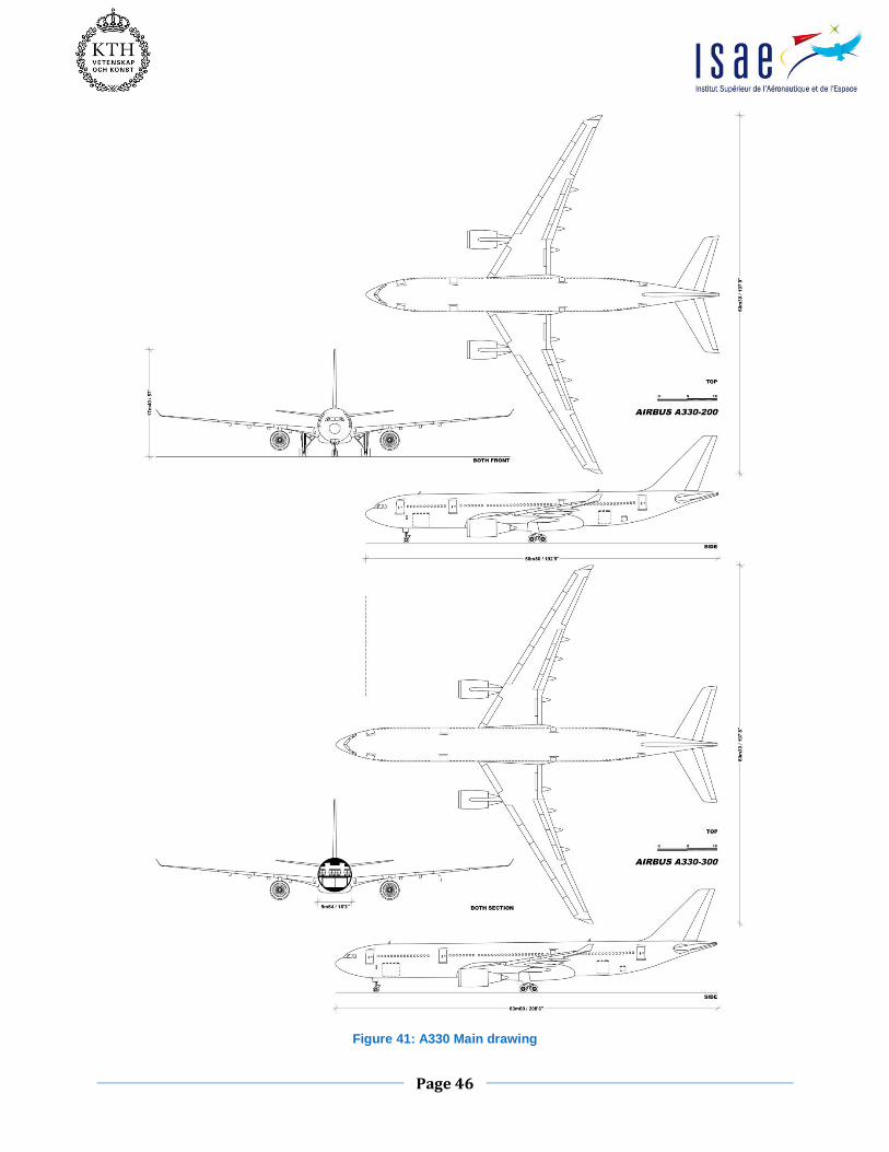
The A330 is available in three versions:
A330-300 A330-200 A330-200F
Compared to the -300, the -200 is shorter of 10 frames (its length is 59 meters). Therefore, the horizontal and vertical stabilizers have been enlarged to compensate for the loss of stability associated with the decrease in length of the fuselage. A cargo version has also been developed. This is the-200F. This aircraft is recognizable with the protruding landing gear box, necessary to hide the higher landing enabling horizontality while on the ground. It can carry a load of 63 tons over a distance of 7800km.
Page 44
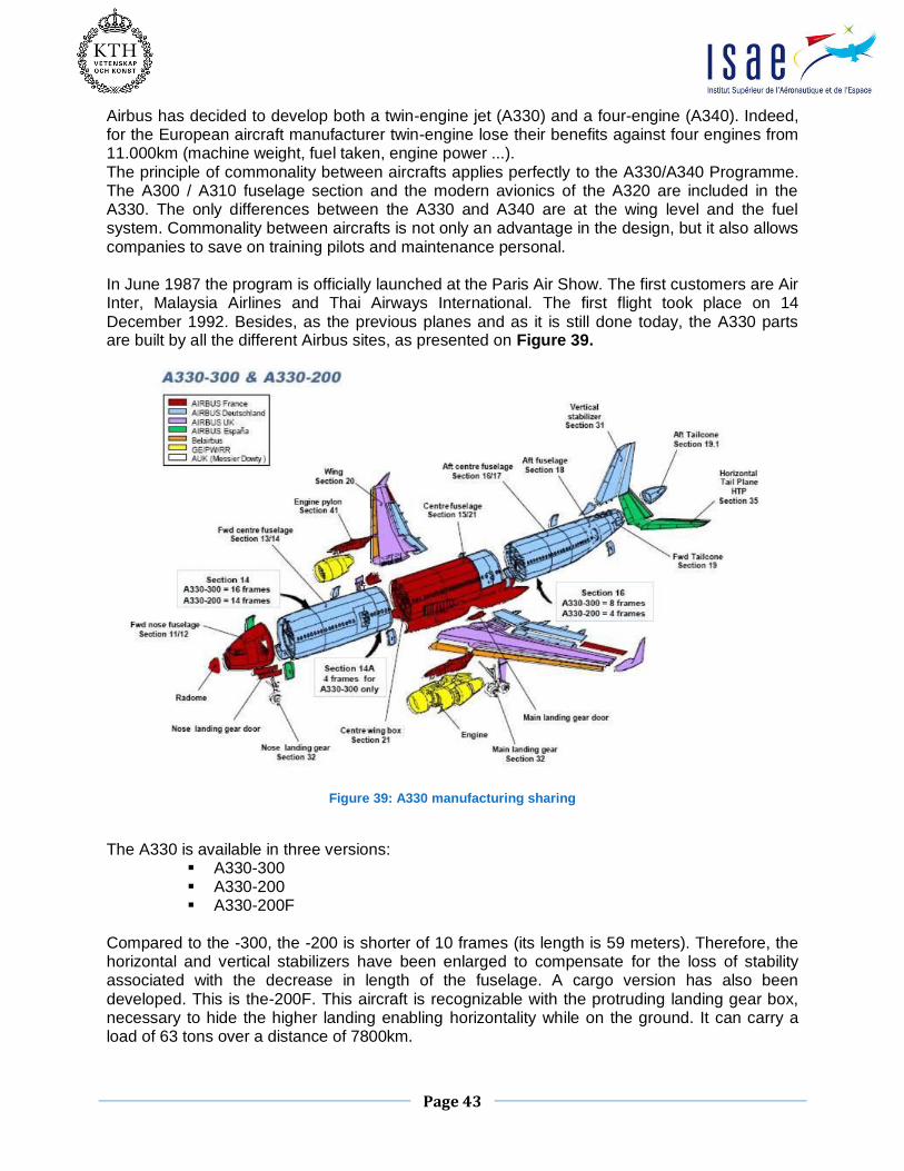
On July 19th 2013, the 1000th A330 was delivered to Cathay Pacific. This is the third type of Airbus plane after the A320 and A319 which has reached this production level.
The following figures – Figure 40 and Figure 41 – are key characteristics and a drawing of the A330.

Page 45
Figure 40: A330 Key characteristics
Page 46
Figure 41: A330 Main drawing