Requirements for the Simulation of Complex Requirements for the Simulation of Complex Heterogeneous...
39
Peter Schwarz 8th Modelica Conference Dresden March 21, 2011 1 Requirements for the Simulation of Complex Heterogeneous Systems 8th Modelica Conference Dresden March 21, 2011 Peter Schwarz Formerly with Fraunhofer Institute for Integrated Circuits, Design Automation Division EAS Dresden, Germany
Transcript of Requirements for the Simulation of Complex Requirements for the Simulation of Complex Heterogeneous...

Peter Schwarz 8th Modelica Conference Dresden March 21, 2011 1
Requirements for the Simulation of Complex Heterogeneous Systems
8th Modelica Conference Dresden March 21, 2011
Peter Schwarz
Formerly withFraunhofer Institute for Integrated Circuits, Design Automation Division EAS Dresden, Germany
Peter Schwarz 8th Modelica Conference Dresden March 21, 2011 2
1. Properties of complex hetereogeneous systems2. Continuous systems3. Hybrid systems4. Spatially distributed systems5. Further requirements and wishes
6. Outlook
Outline
Peter Schwarz 8th Modelica Conference Dresden March 21, 2011 3
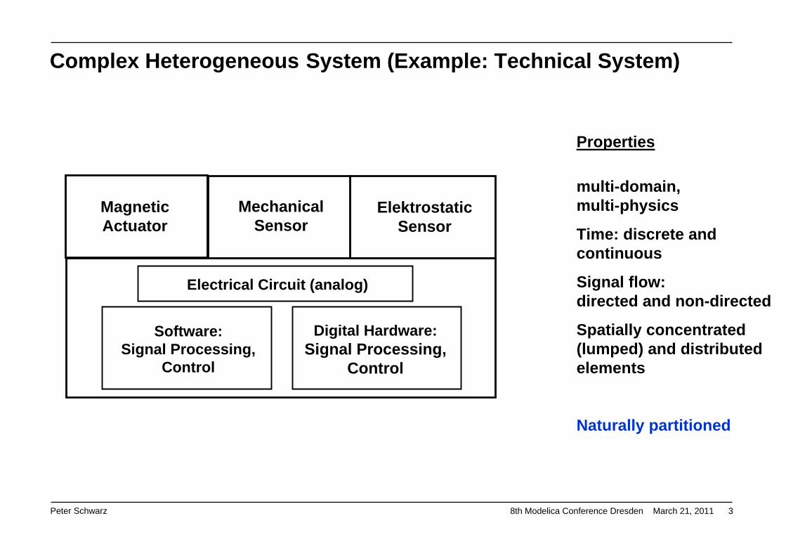
MagneticActuator
ElektrostaticSensor
MechanicalSensor
Electrical Circuit (analog)
Software:Signal Processing,
Control
Digital Hardware:Signal Processing,
Control
Properties
multi-domain,multi-physics
Time: discrete and continuous
Signal flow:directed and non-directed
Spatially concentrated (lumped) and distributed elements
Naturally partitioned
Complex Heterogeneous System (Example: Technical System)

Peter Schwarz 8th Modelica Conference Dresden March 21, 2011 4
MagneticActuator
MechanicalSensor
ElektrostaticSensor
Electrical Circuit (analog)
Software:Signal Processing,
Control
Digital Hardware: Signal Processing,
Control
Heterogeneous System
in general: non-directed signal-flow but also some uni-directional interconnections
Ideal: a heterogeneous model for one simulator – but this is not very realistic for large systems

Peter Schwarz 8th Modelica Conference Dresden March 21, 2011 5
Circuit simulator (analog)
DAE / ODE SimulatorFEM Simulator
MagneticActuator
Electrical Circuit (analog)
Software:Signal Processing,
Control
Digital Hardware: Signal Processing,
Control
Heterogeneous System
ElektrostaticSensor
MechanicalSensor
More realistic: a heterogeneous model and some coupled simulators
Digital simulator, signal processing simulator
in general: non-directed signal-flow but also some uni-directional interconnections
Peter Schwarz 8th Modelica Conference Dresden March 21, 2011 6
1. Properties of complex hetereogeneous systems2. Continuous systems3. Hybrid systems4. Spatially distributed systems5. Further requirements and wishes
6. Outlook
Outline

Peter Schwarz 8th Modelica Conference Dresden March 21, 2011 7
x f (x,u, )t= F(x,x,u, ) 0t =
Control system,signal-flow diagram
Electrical circuit, multi-body system, fluidic system, …
Block diagram Multi-pole network (generalized network)
ODE Ordinary Differential Equation (explicit)
DAE Differential-Algebraic Equation (implicit)
Potential
Flow
+
-
Continuous Systems: Directed and Non-Directed Signal Flow

Peter Schwarz 8th Modelica Conference Dresden March 21, 2011 8
Simulation = sequential processing of statements noticed in correct order by the userMany mathematical algorithms (e.g. RUNGE-KUTTA) in textbooks for solving ODEsODE seems to be the „natural way“ to model the realityFirst DAE solvers
First general-pupose simulation software (e.g. CSMP, CSSL, ACSL) - but oriented on control systems or block diagrams with directed signal flow („block-oriented simulation“)
First simulators for specific technical disciplines (e.g. electrical circuits) with compilers for translating an user-friendly system description (e.g. netlist) into a mathematical model
Two simulation paradigms:
Directed signal flow Non-directed signal flowCausal equations Acausal equations (to be solved simultaneously)Automatic sorting of equations, Formulation of the mathematical description is not trivial:
algebraic loops are not allowed modeling languages and compiler were developed.ODE is the basic model DAE (implicit) is the „natural“ mathematical model Powerful simulation packages Powerful specialized simulators (Spice, ADAMS, …)
Transformation DAE ODE (matrix manipulation, graph sorting, index reduction):very complicated, very time-consuming for nonlinear DAEs, and not successful in some cases
1970
1980
1990
1960
Insight: DAE should be mainly used for „modeling the physical world“
History: Continuous System Simulation

Peter Schwarz 8th Modelica Conference Dresden March 21, 2011 9
History: Continuous System Simulation Hybrid Simulation
Insight: DAE should be mainly used for „modeling the physical world“- and should be coupled with discrete simulation
Consequences
New modeling languages for hybrid systems: Modelica, VHDL-AMS, …
New modeling paradigm: object-oriented modeling, component-based modeling, physical modeling
New powerful hybrid simulators (mixed-signal simulators in electronics)
New multi-physics libraries
This success is coupled with the Modelica community and its protagonists
Francois Cellier, Hilding Elmqvist, Martin Otter, Peter Fritzson, …and many others from universities, research institutions, and companies
But: ODEs are further used, if possible (control systems; partial transformation DAE ODE)
New application areas: code generation, real-time simulation (difficult on DAE basis: ODE)
1990
2000
2010

Peter Schwarz 8th Modelica Conference Dresden March 21, 2011 10
1. Properties of complex hetereogeneous systems2. Continuous systems3. Hybrid systems4. Spatially distributed systems5. Further requirements and wishes
6. Outlook
Outline

Peter Schwarz 8th Modelica Conference Dresden March 21, 2011 11
MagneticActuator
ElektrostaticSensor
MechanicalSensor
Electrical Circuit (analog)
Software:Signal Processing,
Control
Digital Hardware:Signal Processing,
Control
continuousanalog
discretedigital
… with respect to time and / or values
Hybrid simulationMixed-signal simulation
Complex Heterogeneous System and Hybrid Simulation
Peter Schwarz 8th Modelica Conference Dresden March 21, 2011 12
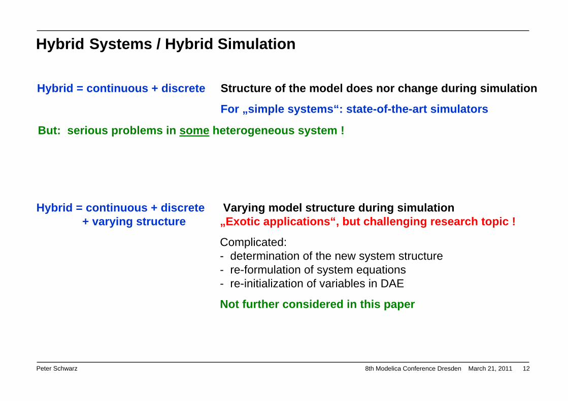
Hybrid = continuous + discrete Structure of the model does nor change during simulation
For „simple systems“: state-of-the-art simulators
Hybrid = continuous + discrete Varying model structure during simulation + varying structure „Exotic applications“, but challenging research topic !
Complicated:- determination of the new system structure- re-formulation of system equations- re-initialization of variables in DAE
Not further considered in this paper
But: serious problems in some heterogeneous system !
Hybrid Systems / Hybrid Simulation

Peter Schwarz 8th Modelica Conference Dresden March 21, 2011 13
Continuous simulation (ODE, DAE)CSSL, Matlab, MatrixX (ODE); Spice (DAE)
Discrete event simulation (DEVS)GPSS; VHDL and Verilog simulators (electronics)
Extension: improved discrete control mechanisms: state charts, Petri nets
Typical: very large, stiff ODE / DAE,small number of events
Applications: chemical processes, robotics, mechanics, control systems
Extensions to continuous subsystems: Hybrid DEVS; DAE solvers (mixed-signal simulation)
Typical: hugh number of events ( billions ! )event queues, small number of ODEs / DAEs
Applications: manufacturing systems, analog + digital electronics (10 … 100 Mio. digital components)
Dymola, SimulationXMatlab/Simulink/Stateflow/Simscape
MatrixX, NI Labview, MapleSim
VHDL-AMS simulators Verilog-AMS simulators( AnyLogic )
Problem: very fast AND very slow AND very large number of eventssignal changes
Hybrid Systems / Hybrid Simulation - the Roots

Peter Schwarz 8th Modelica Conference Dresden March 21, 2011 14
UML state diagram
Discrete System: Graphical Description with State Charts (1)
Informal state diagram …extended to hybrid systems
A. Schneider, FhG IIS/EAS
SimulationX
U. Donath, FhG IIS/EAS

Peter Schwarz 8th Modelica Conference Dresden March 21, 2011 15
Discrete System: Graphical Description with State Charts (2)
State Graph Libraries (Modelica)
Many similar types of diagrams are in use!
No really accepted standard
UML could be considered as a de-facto standard
But: not ambiguous for simulation !!!
Additional definitions are necessary, e.g.:
- priority rules
- separate blocks for event scheduling
and should NOT be tool-dependent !

Peter Schwarz 8th Modelica Conference Dresden March 21, 2011 16
Example with the hybrid simulator AnyLogic:time-triggerd switching between differential equations
State 1
State 2
1 s 1 s
t in s
x2
x3
1 2 3 4
x1x1x2x3
x1´ = a1*x1 + a2*x2 + a3*x3
x2´ = b1*x1 + b2*x2 + b3*x3
x3´ = c1*x1 + c2*x2 + c3*x3
x1´ = d*x1 + 3
Hybrid Systems and State Charts
Root:x1(0) = 0, x2(0) = 0, x3(0) = 0,a1 = …, … ,d = …
Initial conditions
Peter Schwarz 8th Modelica Conference Dresden March 21, 2011 17
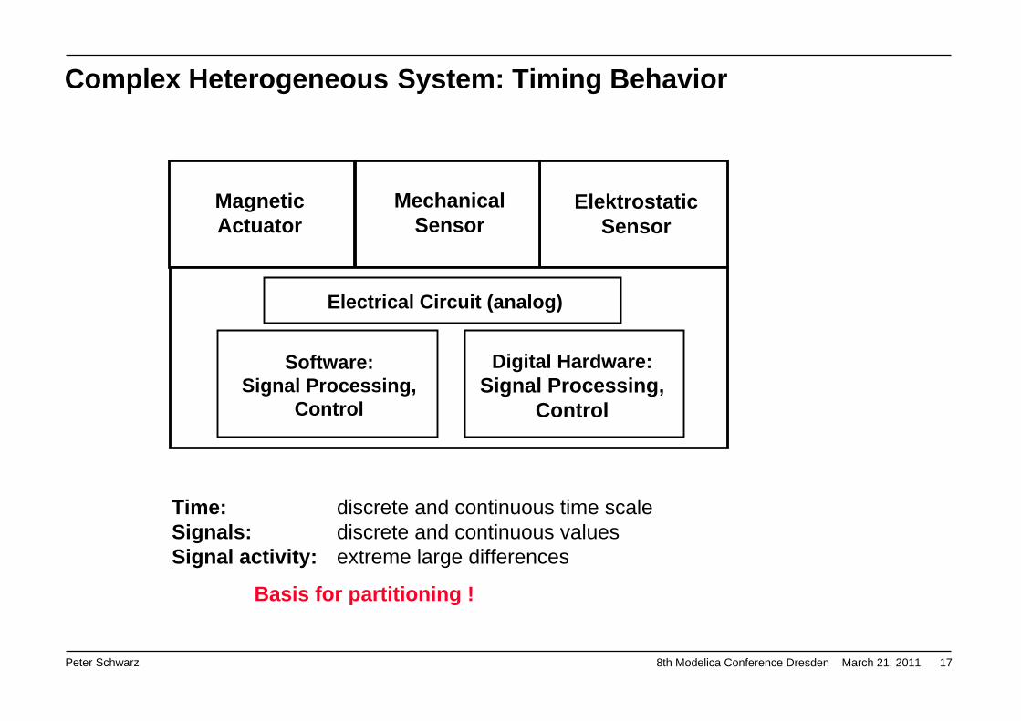
Complex Heterogeneous System: Timing Behavior
MagneticActuator
ElektrostaticSensor
MechanicalSensor
Electrical Circuit (analog)
Software:Signal Processing,
Control
Digital Hardware:Signal Processing,
Control
Time: discrete and continuous time scaleSignals: discrete and continuous valuesSignal activity: extreme large differences
Basis for partitioning !

Peter Schwarz 8th Modelica Conference Dresden March 21, 2011 18
Synchronization layer
very intensiveinteraction
time-consumingsimulation!
reduced,controlledinteraction
A slow A fast
D fast D slow
Partitioning w.r.t Timing Behavior
Not an academic idea!
It has been realized, e.g., in a SystemC-AMS simulation environment
Peter Schwarz 8th Modelica Conference Dresden March 21, 2011 19
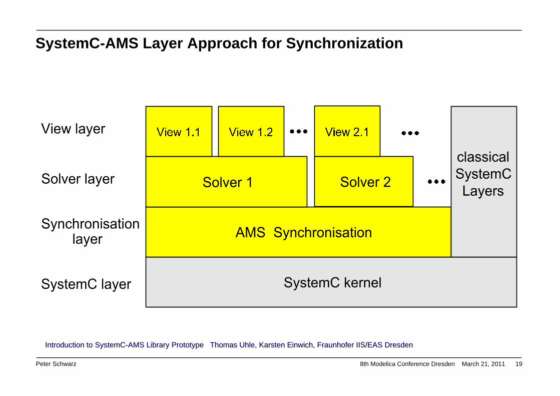
SystemC-AMS Layer Approach for Synchronization
Introduction to SystemCIntroduction to SystemC--AMS Library PrototypeAMS Library Prototype Thomas Thomas UhleUhle, Karsten , Karsten EinwichEinwich, Fraunhofer IIS/EAS , Fraunhofer IIS/EAS DresdenDresden

Peter Schwarz 8th Modelica Conference Dresden March 21, 2011 20
Nonlinear DAESolver supporting
the synchronization interface
nonlinear module, node and variable
base classesLinear
behaviour
Linear electrical networks
Linear DAE solver
SystemC-AMS Layer Approach for Synchronization
Introduction to SystemCIntroduction to SystemC--AMS Library PrototypeAMS Library Prototype Thomas Thomas UhleUhle, Karsten , Karsten EinwichEinwich, Fraunhofer IIS/EAS , Fraunhofer IIS/EAS DresdenDresden

Peter Schwarz 8th Modelica Conference Dresden March 21, 2011 21
Modem IC: Analog + Digital + Software
Voice band 50 Hz … 12 kHz ( … XDSL: 2 MHz )Analog filter 100 kHzDigital filter 64 … 256 MHz clock, oversamplingMany prozessors programmable functionality
The Integrated Circuit has to be simulated together with its environment (simulation of adaptive behavior)
Clock pulses and analog signals:50 Hz up to 256 MHz (events: > 1 GHz)

Peter Schwarz 8th Modelica Conference Dresden March 21, 2011 22
1. Properties of complex hetereogeneous systems2. Continuous systems3. Hybrid systems4. Spatially distributed systems5. Further requirements and wishes
6. Outlook
Outline

Peter Schwarz 8th Modelica Conference Dresden March 21, 2011 23
Two- or three-dimensional components (sometimes with very complicated geometryand coupled physical domains)- Solving partial differential equations (PDE) with boundary conditions- Application of FEM simulators (ANSYS, NASTRAN, …)
If the distributed components have to be considered together with other subsystems (sensors, signalprocessing, control, …):
Coupling with a system simulator (co-simulation)Powerful but very time consuming
Alternative:Approximate solution only with the system simulatorNecessary: models with reduced but sufficient
accuracy
-+
Spatially Distributed Components

Peter Schwarz 8th Modelica Conference Dresden March 21, 2011 24
Model generation: the PDE is numerically approximated by a system ofODEs or DAEs (e.g. with central differences)
-+
Model library
behavioral model(equations)
Spatially Distributed Components
Peter Schwarz 8th Modelica Conference Dresden March 21, 2011 25
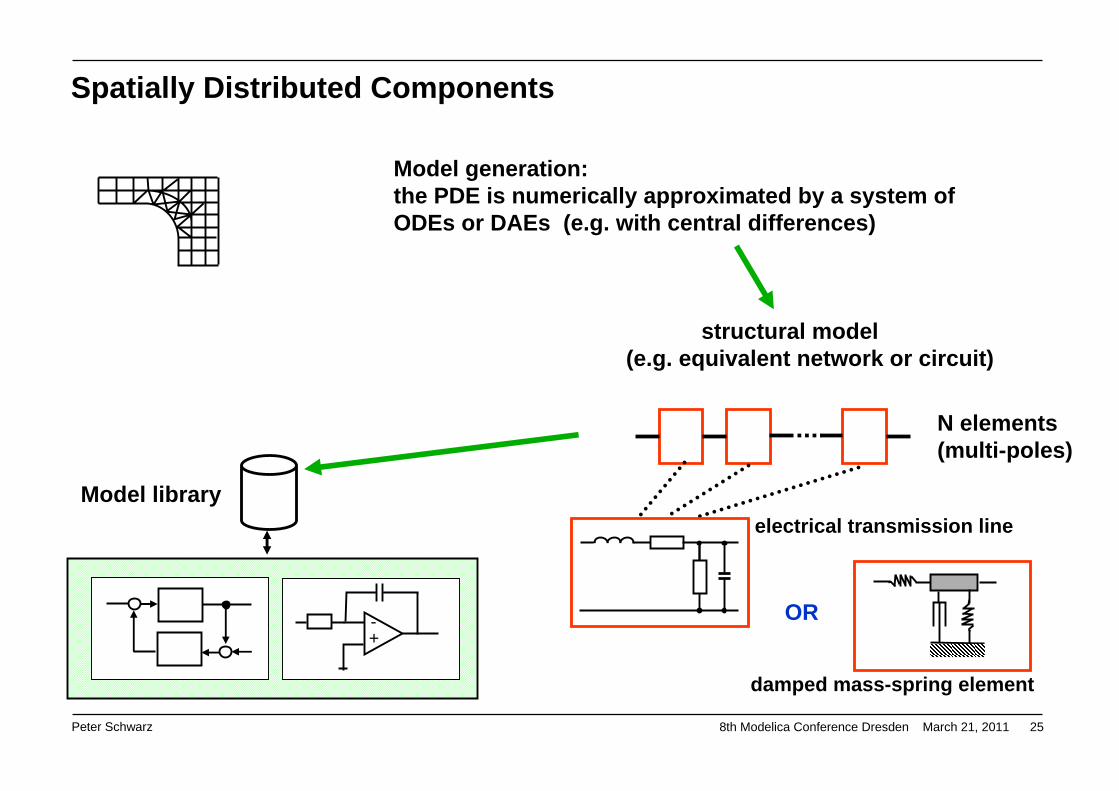
Model generation: the PDE is numerically approximated by a system ofODEs or DAEs (e.g. with central differences)
-+
Model library
structural model(e.g. equivalent network or circuit)
N elements(multi-poles)
Spatially Distributed Components
electrical transmission line
damped mass-spring element
OR
Peter Schwarz 8th Modelica Conference Dresden March 21, 2011 26
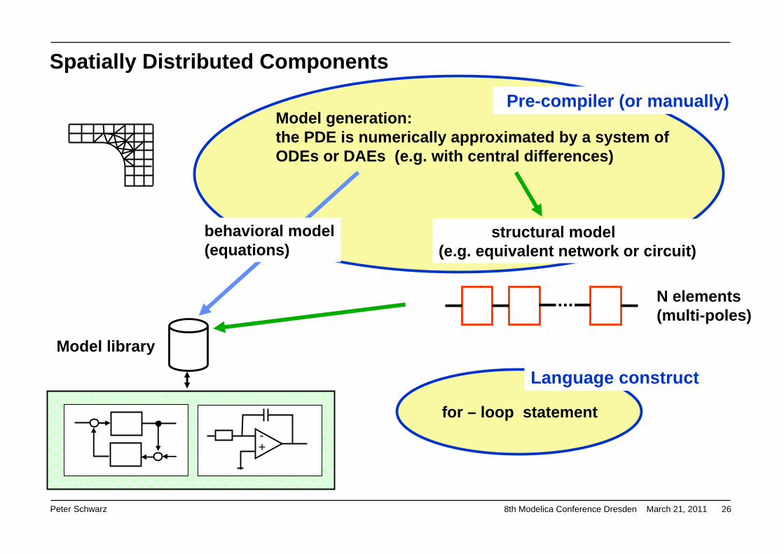
Model generation: the PDE is numerically approximated by a system ofODEs or DAEs (e.g. with central differences)
-+
Model library
N elements(multi-poles)
Spatially Distributed Components
structural model(e.g. equivalent network or circuit)
Pre-compiler (or manually)
Language construct
for – loop statement
behavioral model(equations)

Peter Schwarz 8th Modelica Conference Dresden March 21, 2011 27
Modelica.Electrical.Analog;package Lines
"Lossy and lossless segmented transmission lines and LC distributed line models"extends Modelica.Icons.Package;model OLine "Lossy Transmission Line"
Interfaces.Pin p1 ;Interfaces.Pin p2 ;Interfaces.Pin p3 ;SI.Voltage v13;SI.Voltage v23;SI.Current i1;SI.Current i2;parameter Real r "Resistance per meter";parameter Real l "Inductance per meter";parameter Real g "Conductance per meter";parameter Real c "Capacitance per meter";parameter SI.Length length "Length of line";parameter Integer N "Number of lumped segments";
one segment
Spatially Distributed Components: Electrical Transmission Line
C. Clauss, FhG IIS/EAS

Peter Schwarz 8th Modelica Conference Dresden March 21, 2011 28
protectedBasic.Resistor R[N + 1](R=fill(r*length/(N + 1), N + 1));Basic.Inductor L[N + 1](L=fill(l*length/(N + 1), N + 1));Basic.Capacitor C[N](C=fill(c*length/(N), N));Basic.Conductor G[N](G=fill(g*length/(N), N));
equationv13 = p1.v - p3.v;v23 = p2.v - p3.v;i1 = p1.i;i2 = p2.i;
connect(p1, R[1].p);for i in 1:N loop
connect(R[i].n, L[i].p);connect(L[i].n, C[i].p);connect(L[i].n, G[i].p);connect(C[i].n, p3);connect(G[i].n, p3);connect(L[i].n, R[i + 1].p);
end for;connect(R[N + 1].n, L[N + 1].p);connect(L[N + 1].n, p2);
end OLine;
Segment i
one segment
Spatially Distributed Components: Electrical Transmission Line
C. Clauss, FhG IIS/EAS

Peter Schwarz 8th Modelica Conference Dresden March 21, 2011 29
Fp
Fn
Fr
Fg
model Thread extends TwoFlange;parameter Integer N=10;parameter Real L = 1;parameter Real c = 1;parameter Real m = 1;parameter Real d = 0;parameter Real[2] s0 = {1, 0};parameter Real[2] v0 = {0, 0};SpringMass springMass[N-1]
(each L=L/N, each c=c,each m=m/(N-1), each d=d);Spring spring(L=L/N, c=c);
initial equationfor i in 1:N-1 loop
springMass[i].mass.s = s0/N*i;springMass[i].mass.v = v0/N*i;
end for;equation
connect(p, springMass[1].p);for i in 2:N-1 loop
connect(springMass[i-1].n, springMass[i].p);end for;connect(springMass[N-1].n, spring.p);connect(spring.n, n);
end Thread;A. Schneider, FhG IIS/EAS
Spatially Distributed Components: Pendulum

Peter Schwarz 8th Modelica Conference Dresden March 21, 2011 30
1. Properties of complex hetereogeneous systems2. Continuous systems3. Hybrid systems4. Spatially distributed systems5. Further requirements and wishes
6. Outlook
Outline

Peter Schwarz 8th Modelica Conference Dresden March 21, 2011 31
Further Requirements and Wishes (1) Model interfaces A MUST
Very important for
- Model exchange between different simulation environments (based on the same modelinglanguage, e.g. Modelica)
- Embedding models with own simulation algorithm, independent of the modeling language(executable). This could be interpreted as a special form of co-simulation.
The advanced user needs some simulator-internal data (not only signal values)
Many papers on “Functional Model Interface – FMI” will be presented at this conference!
Co-Simulation A MUST
- Coupling with other commercial simulators (e.g. FEM simulators or Matlab/Simulink)
- Embedding special simulation algorithms:
Handling of very large continuous systems with reduced accuracy (e.g. iterated timing analysis: GAUSS-SEIDEL or GAUSS-JACOBI iteration of DAE)
DEVS algorithms optimized for a hugh number of events
Specialized simulators for hardware components (microcontroller, digital signal processors)

Peter Schwarz 8th Modelica Conference Dresden March 21, 2011 32
Further Requirements and Wishes (2) Code generation from model description A MUST(Hardware-in-the-loop simulation, controller design)
- Relatively simple from ODEs (see, e.g., Matlab/Simulink, since many years!)
- Complicated from DAEs: many restrictions, internal simplifications or approximations:is the user informed in necessary detail?
- How reliable are the guarantees for maximal sample rate?
Improvements of simulation algorithms Nice to have
- Exploiting the sparseness of large continuous system descriptions, sparse matrix techniques(SMT): symbolical and/or numericalThe effects strongly depend on simulator implementation!
- Handling of events in discrete systems: Very large number of eventsExplicit access to event queues (extensions of the modeling language are mostly necessary!)

Peter Schwarz 8th Modelica Conference Dresden March 21, 2011 33
Further Requirements and Wishes (3) Export of mathematical model descriptions Nice to have
- Complete set of equations?
Not really the goal of simulator vendors! But interesting for external model simplification, e.g., with the program “Analog Insydes” (symbolic approximation of nonlinear DAE systems)
- Partial model descriptions:
Linearized state equationsODEs or DAEs of linear subsystems
for external postprocessing:calculation of eigenvalues, model order reduction (MOR) for very large systems
Consideration of statistical effects Nice to have
Monte Carlo simulation, advanced statistical analysis (e.g. importance sampling), tolerances and parameter variations, reliability
See the SAE J 2748 VHDL-AMS Statistical Analysis Package“At the beginning of each simulation run the parameters are initialized using random values distributed in accordance with the associated probability density or cumulative density function. Every VHDL-AMS/VHDL simulator that allows for multiple runs can be used for setting up standard Monte Carlo experiments.”
( J. Haase, C Sohrmann, IEEE BMAS Conf. 2009 )

Peter Schwarz 8th Modelica Conference Dresden March 21, 2011 34
Further Requirements and Wishes (4) Co-existence of different modeling languages Acceptance is a MUST
Modelica VHDL-AMS Verilog-AMS SystemC-AMS ( OSCI standard ) Matlab/Simulink/Stateflow Simscape ???
Consequences for modeling guidelines: model structure, avoiding very special constructs, …
Automatic model transformation does not seem to be very successful
Improved graphical description of discrete systems A MUST
UML could become a de-facto standard, but is not ambiguous for simulation
Additional definitions are necessary for unambiguous simulation:
- As close as possible to the UML standard
- Tool-independent part of the modeling language!
- State-chart libraries are a first step to extended modeling languages

Peter Schwarz 8th Modelica Conference Dresden March 21, 2011 35
Further Requirements and Wishes (5) Improved user communication and simulator handling Very nice to have
- Error handling, debugging, and tracing: backtracking to the original model source code
- Tracing through the actual state (following the signal flow) and into the past
- Localization of the reasons of numerical problems and errors (overflow, extreme stiffness, infinite iteration loops, higher index DAE, …) - combined with backtracking to the original modelsource code
- Breakpoints and restart from different breakpoints
Coupling simulation with formal verification Nice to have
Goal: detect as many as possible errors without simulation – but use simulation if necessary
Principles (only some examples):
- Simple syntax check of model source code
- More sophisticated model analysis (model checking)
- Searching for deadlocks and infinite loops in Finite State Machines or PETRI nets
- Assertion-based simulation

Peter Schwarz 8th Modelica Conference Dresden March 21, 2011 36
1. Properties of complex hetereogeneous systems2. Continuous systems3. Hybrid systems4. Spatially distributed systems5. Further requirements and wishes
6. Outlook
Outline

Peter Schwarz 8th Modelica Conference Dresden March 21, 2011 37
Outlook (1)A very interesting system simulation scenario:
- Large system of individuums (each one may be a multi-physics system or a very simple object)
- The individual systems have their own control algorithms and exchange information with their environment
- There are some global control algorithms
- The location of the individuums and the communication between them may be organized worldwide (delayed information)
- The individuums may switch off from / on to the community (“system with varying structure”)
- System monitoring, evaluation, control, and exchange of information need very large computational power (grids, clouds)
- Large influence of non-deterministic behavior (statistical parameter variation, random inputsignals, and non-deterministic control decisions)
Cyber-Physical SystemsA new buzzword or a serious trend in simulation of complex systems ?
Peter Schwarz 8th Modelica Conference Dresden March 21, 2011 38
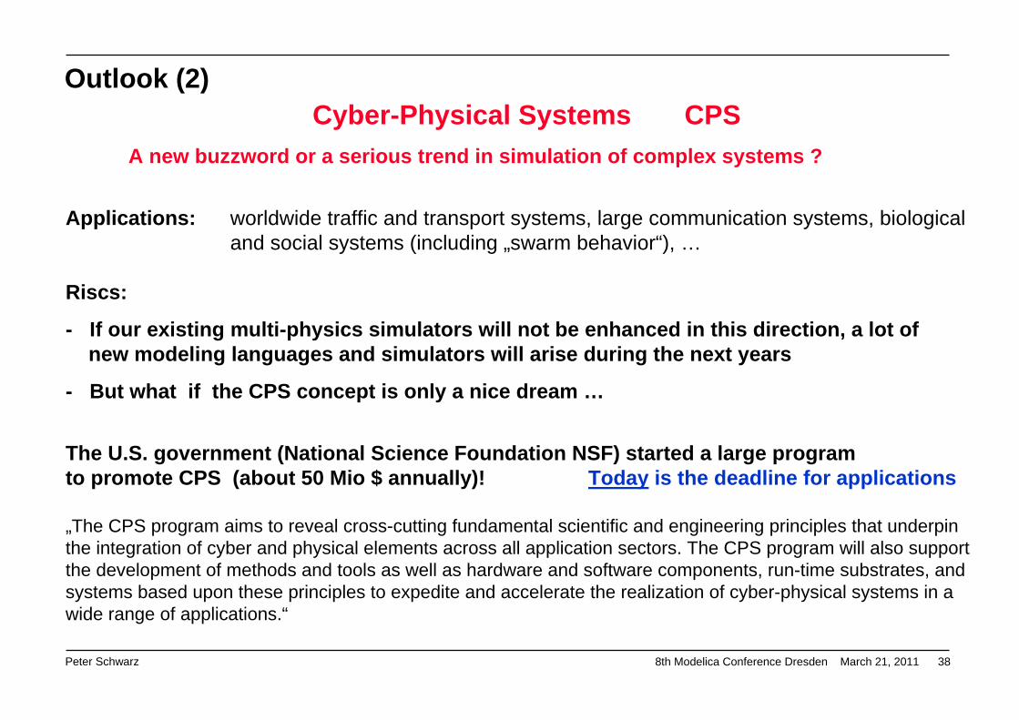
Outlook (2)Cyber-Physical Systems CPS
A new buzzword or a serious trend in simulation of complex systems ?
Applications: worldwide traffic and transport systems, large communication systems, biologicaland social systems (including „swarm behavior“), …
Riscs:
- If our existing multi-physics simulators will not be enhanced in this direction, a lot of new modeling languages and simulators will arise during the next years
- But what if the CPS concept is only a nice dream …
The U.S. government (National Science Foundation NSF) started a large program to promote CPS (about 50 Mio $ annually)! Today is the deadline for applications
„The CPS program aims to reveal cross-cutting fundamental scientific and engineering principles that underpin the integration of cyber and physical elements across all application sectors. The CPS program will also support the development of methods and tools as well as hardware and software components, run-time substrates, and systems based upon these principles to expedite and accelerate the realization of cyber-physical systems in a wide range of applications.“
Peter Schwarz 8th Modelica Conference Dresden March 21, 2011 39
Thank you for your attention !
And my special thanks to my former colleagues at Fraunhofer IIS / EAS Dresden, especially to
Christoph Clauss Ulrich Donath Karsten Einwich Günther Elst
Joachim Haase Jürgen Haufe André Schneider Peter Schneider
Their experiences and support have strongly influenced this presentation.