Requirements for Charged Particle Medical Accelerators
23
... ... ... - Requirements for Charged Particle Medical Accelerators * LBL Experience William T. Chu Lawrence Berkeley Laboratory University of California, Berkeley, CA 94720 (To be presented at the Workshop on Accelerators for Charged-Particle Beam Therapy, Fermi National Accelerator Laboratory, January 24 and 25, 1985.) * This work was supported by the US Department of Energy contract No. DE-AC03-76SF00098 and in part by the National Institute of Health under Grant Ca15184 . 67
Transcript of Requirements for Charged Particle Medical Accelerators

...
...
...-
Requirements for Charged Particle Medical Accelerators*LBL Experience
William T. Chu
Lawrence Berkeley Laboratory
University of California, Berkeley, CA 94720
(To be presented at the Workshop on Accelerators for
Charged-Particle Beam Therapy, Fermi National Accelerator
Laboratory, January 24 and 25, 1985.)
*This work was supported by the US Department of Energy~nder contract No. DE-AC03-76SF00098 and in part by theNational Institute of Health under Grant Ca15184 .
67

1. Introduction - ..At the Lawrence Berkeley Laboratory of the University of California,
Berkeley. the 184-Inch Cyclotron and the Bevalac have provided acceleratedheavy ions for biomedical applications ranging from basic research toradiation treatment of human cancer. These experiences coupled with the LBLexpertise in accelerator technology have prompted us to plan for ahospital-based heavy-ion medical accelerator (Alpen (1984).
At t.his proposed facility, accelerated heavy ion beams can be producedsuitable for t.reatment of human cancer. These same beams can be effectivelyutilized to pursue other clinical and basic research activities. Theaccelerator system is contemplated to reliably accelerate a wide range of ionspecies, from helium to argon, to energies as low as 70 KeV/amu for 4-cm range
4He beams to as high as 800 HeV/amu for 30-cm range 28Si beams, withintensities sufficient to limit treatment times to about one minute.
Secondary radioactive heavy ion beams, such as lIe and 19Ne , will al-so beavailable to aid the accurate treatment planning as well as broaden the baseof scientific research that can be conducted at this facility. In addition,the species of ions could be extended to include protons and moderate
intensities of 56 Fe beams, adequate to support research programs inbiophysics and related fields of scient.ific inquiry.
The beams can be delivered sequentially to multiple treatment rooms toaccommodate as many as 100 patients per day in addition to provide for theneeds of an intensive program in basic research. Estimates of the projectsoperating costs for this facility suggest that the incremental cost perpatient treatment is modest in the context of alternative radiationtreatment. The main accelerator component required to produce 800 KeV/amubeams is a synchrotron ring approximately 30 meters in diameter. Such anaccelerator could be located in a major medical complex to providecost-effective medical care and to support a forefront research program inhigh technology medicine.
II. Advantages of High-LET Charged Particle Beams
There is a strong rationale to perform a randomized radiotherapy trialwith heavy charged particles at a hospital-based facility. The hypothesis tobe tested may be briefly formulated as follows: Given the fact that particlebeams of both low and high atomic numbers can achieve superior doselocalization. will the heavier ions produce better local control of humancancer than light ions? We expect better results because of the advantageousradiobiological characteristics of the heavier ions.
Hypoxic parts of turner tissues, for example cells located near necroticfoci. are much more resistant to conventional radiation. Experiments haveshown, however, that while this resistance exists for low-LET charged particleirradiation, it does not exist for heavy-ion irradiation: Hypoxic cells arenearly as sensitive to heavy-ion irradiation as oxic cells.
Cells in rapidly growing turners are asynchronous. Cells in the S phaseof the DNA synthesis cycle are much more resistant to low-LET radiation thancells in othet' phases of the cycle; therefore, in protracted radiotherapythere are usually sut'viving·· cells that are protected against low-LETradiation. Heavier charged particles such as 8i ar Ar ions greatly diminishthe differences in radiosensitivity for cells at any phase of cell division;
fewer protected cells are expected to survive after a dose of heavy ions.
68
-
-----
---...r
-
-
-
--

whichemissionachievedincluding
-
-
,
There are several types of molecular repair mechanisms known in cellsexposed to low atomic-number particles at low LET. Such repair becomeslargely ineffective when heavy ions are used. As a result the Bragg peaks ofheavy ions are much effective than low-LET radiations.
The combination of these factors is expected to make heavy ionsparticularly effective for the treatment of well-localizable tumors that haveradioresistant cell populations.
In addition, maximizing the dose to the local cancet" while minimizingdose to the surrounding normal tissues offers the highest potential for tumorcontrol. The physical properties of charged particles, including heavyparticles and protons, permit dose localization superior to that achievablewith neutrons. The particle range, or degree of dose localization in thepatient, can be determ.ined with great precision by technique
11 19utilize radioactive beams, such as C and Ne, and positrontomography. Superior treatment planning and verification can bewith these particle compared with any other radiation modalityprotons and helium nuclei.
Fig. 1 demonstrates how the consideration of both physical doselocalization advantage and the cOt-responding enhancement of biological cellkilling effectiveness influences the various radiation modalities. theabscissa in these plots is the ratio of biologically effective doses definedas:
(Dose x RBE se) at mid target volume
Effective dose ratio =
(Dose x RBESO) at entrance
It is regarded as more advantageous to use the charged particles that arefurther out to the right on this axis of the effective dose ratio. When theeffective dose ratios are comparable, the modalities that exhibit lower OER(Oxygen Enhancement Ratio) will be the better choice.
The data are based on measurements made with the cultured cells invitro. The top panel is constructed for a 10-cm x 10-cm x ii-em deep fieldwith the distal edge of the target volume at 14-cm deep. The bottom panel is
3for a 10 x 10 x 10 cm target volume with the 24-cm deep distal edge.
For smaller, more shallow tat"get volume (top panel), it appears that C,Ne, and negative pion beams are superior in their ratio of bilogicallyeffective doses. Ar and Si ion beams and p and He ion beams are intermediatein this ratio, but quite different from each other with respect to their OERvalues.
For a larger, deeper turner volume (bottom panel), the C and He ion beamsare quite similar, as are the Ne ion and negative pion beams; however, thereare quite distinct division on OER values between low-LET and high-LETparticle beams.
III. Dose Localization
The localization of the radiation dose in the target volume is limited bymany causes. The range strag'gling, of the charged particles in the slowingmedium makes the distal edge of the radiation field not sharp. The energyspread in the accelerated beams, as well as the energy fluctuation from pulse
69

to pulse result in the same effect. The emittance of the beam and themultiple scattering of the charged particles in the beam path and inside thepatient body both contribute in the lateral spreading of the beam and broaderpenumbra. Also these effects lower the peak-to-plateau ratios of the chargedparticle beams that are collimated to small sizes.
(A) Energy Loss Rate for Heavy Charged Particles:
A heavy pr-ojectile, much mor-e massive than an electr-on, of charge Ze,incident at speed (3c «(3»11137) through a slowing medium, dissipates energymainly bia interactions with the electrons of the medium. The m~an rate ofsuch energy loss per- unit length x, dE/dx, called the stopping power, is givenby the Bethe-Bloch equation. The stopping power is closely related to LET(Linear- Energy Transfer-). The LET is proportional to the square of the chargeof the incident par-ticle, to the reciprocal of kinetic energy (liE), and tothe electron density of the slowing medium.
We may approximately treat media which are chemical mixtures or compoundsby computing (Bethe and Ashkin (1959»
dE=
dx
with (dE/dx) appropriate to the i-th chemical constituent, using the partialdensity in the formula for dE/dx. For many chemical compounds, smallcorrections to this additivity rule may be found in Berger and Seltzer (1982).
In the stopping region, the stopping power formula becomes inapplicable.At the very s lowest speeds, total energy loss rates are proportional to 13.The energy loss rate passes through a small peak at intermediate speeds due toelastic Coulomb collisions with the nuclei of the slowing medium (Sidenius(1974» and rise through a larger peak at projectile speeds comparable toatomic speeds <13 on the order of ac).
The mean r-ange, R, of the charged particles in the slowing medium isobtained by integrating the stopping power equation given above:
R =1O__~_E_'_dE/dx
The range-energy relationship for several heavy ions in water werecalculated by Stewart (1967). Measurements and calculations of range-energyrelationship for heavy ions were also made by Northcliffe (1963). by Barkasand Berger (1964), and by Eby and Morgan (1972). For a given medium, therange R'of any other beam particle with mass H'and charge Z'is given in termsof the range R of other particle with mass H and charge Z and having the equalvelocity is given by
---
----
---
---
-
R' =Z' IZ
R
70
--
,..,-
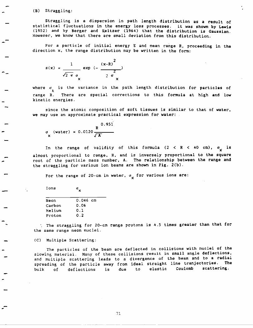
(B) Stt"aggling:
Straggling is a dispersion in path length distribution as a result ofstatistical fluctuations in the energy loss processes. it was shown by Lewis(1952) and by Berger and S.eltzer (1964) that the distribution is Gaussian.However, we know that there are small deviation from this distribution.
For a particle of initial energy E and mean range R, proceeding in thedirection x, the range distribution may be written in the form:
21 (x-R)
s (x) = exp (- )
.;'2-; 02
2 0x x
where 0 is the variance in the path length distribution for particles ofx.
range R. There are special corrections to this formula at high and lowkinetic energies.
since the atomic composition of soft tissues is similar to that of water.we may use an approximate practical expression for water:
0.951R
o (water) = 0.0120-==---x .[P:
almost proportional to range. R. and is inversely proportionalroot of the particle mass number, A. The relationship betweenthe straggling for various ion beams are shown in Fig. 2(b).
isIn the range of validity of this formula (2 < R < 40 cm), 0x
to the squarethe range and
--
For the range of 20-cm in water, 0 for various ions are:x
Ions 0 x
Neon 0.046 cmCarbon 0.06Helium 0.1Proton 0.2
The straggling for 20-cm range protons is 4.5 times greater than that forthe same range neon nuclei.
(C) Multiple scattering:
The particles of the beam are deflected in collisions with nuclei of theslowing material. Many of these collisions result in small angle deflections,and multiple scattering leads to a divergence of the beam and to a radialspreading of the particle away from ideal straight line tranjectories. Thebulk of deflections is due to elastic Coulomb scattering.
71

There is a small correction due to the tontribution of strong interactions tt~e :ota: multiple scatt~ring for the hadronic projectiles. The angUla~dlStnbutlon from the multlple scatledng is roughly Gaussian only for smalldeflection angles, while it shows much greater probability for large-anglescattering than the Gaussian would suggest.
--
-
0.0294 Ra =y -------------
At range R the projected radial distribution of deflection y of theparticle is given by:
1 yP(y) = exp (- )
&0----,--20
Y Y
where 0y is approximately given by:
0.896
0.207Z A
0.396
-----
The relationship betweenvarious ion beams are shown ina for various ions are:y
Ions ay
Neon 0.082 cmCarbon 0.11Helium 0.22Proton 0.43
the rangesFib. 2(c).
and the multiple ~cattering forFor the range of 20-cm in water,
•
of C0 fill'
Y
10-5 -
The multiple scattering for protons is about 5 times gt"eater than thatfor the same range neons.
(D) Emittance of the Beam
The emittance of the extt'ac ted beam detennines the phase space of thecharged pat"ticles tranported into the target volume. Fot" example, if weconsider the Ne ion beam of 20-cm t"ange R with a diametet" D of 5-cm (e.g.,beam spot size for scanned beam), the multiple scattering gives a _ 0.05
Yem. A comparable divet"gence is attained if the emittance is E «- 0 a IR "" 1
y
x 10-4
ineter-t"adian. For focal lesion application, we take 10-cm t"angeion beam with a diameter of 0.5 em, then the multiple scattering gives
0.1 em. The comparable divergence is obtained for the emittance e _ 4 xm-rad.
----
The design value of the emittance for the proposed accelerator is 2 x-5
10 m-rad, which is about a half of the above estimates. Since the effectsof the multiple scattet"ing and emittance add statistically, 1/2 as bigdivergence due to the finite size of emittance contributes only 1/4 in the -spreading of penumbra.
-72

--
-
---
-
--
(E) Peak-to-Plateau Ratios and PenumbLa
The diverging beams and multiple scattering in the slowin~ medium generallybLoaden the beams, and lower the peak-to-plateau r-atios. The effect is mor~
pLonounced fOL smaller' beams as mOLe paLticles scatteL out of the originaltrajectories than those scatteLing in. Fig. 3 shows the 20-cm range protonand He ion beams: the central-Lay doses for large beams and collimated beamsare nor-malized at the entrance. ExpeLimentally measuLed Bragg CULves fOL 225HeV/amu He ion beam and for 308 HeV/amu C ion beam are shown in Fig. 4 as afunction of residual Langes.
The dose profiles of pLoton and C ion beams thLough a l-cm slit aredepicted in Fig. 5. The pLoton beam pLofiles ar-e shown. eitheL nOLmalized atthe peak or' at the entLance. The fOLmer shows that the penumbra for protonbeam is about squaLe-root of 12 times bigger than that of C ion beam, and thelatter shows that the peak-to-plateau ratio is dec Leased by about 40% forproton beam compared with that of C ion beam.
OUr- expeLiences in clinical situations using He ion beams at the 184-InchCyclotron and the heavy ion beams at the Bevalac generally SUPPOLt the aboveanalyses. The double scattering system that lateLally spreads the beam byscattering materials in the beam path also contributes in. broadening thepenumbr-as. The wobbler system, that uses no scattering material in the beampath, produces narrower penumbra compared with those obtained through thedouble scattering method.
(F) Radioactive Beam Ranging Technique
Although t.he charged particle beams exhibit sharply defined ranges asdiscussed above, the accuracy of delivering t.he radiation dose into awell-defined target volume is only as accurate as the knowledge of theint.egral water-equivalent thickness of the intervening tissues. The x-CTsupplies infor-mation on t.he distribution of x-ray absorption coefficients, andaccurate conver-sicns of the x-CT dat.a into the stopping powers of the mediumfor charged particles are not possible. The He and Ne ion measurements usinga fr-ozen beagle and comparing them with x-CT data indicates that the x-CTmeasur-ements are off as much as 0.4 cm out of 5 cm range in brain and thorax(Table 2). The HRI data may augment the x-CT data by measuring the chemicalcomposition of the tissues, yet they are not sufficient to supply theinfor-mation of the stopping power of the tissues. Whereas the stoppingradioactive beams directly measure the integral stopping power of the mediumin water- equivalent thickness.
Positron emitter-s, cll, N13 , 015 , F17 , and Ne19 , result when their-12 14 15 18 20respective stable par-ent paLticles, C ,N ,0 , F ,Ne ,pass through an
absorbing material. For example, 530 HeV/amu Ne 20 , beam is put through a2.5-cm thick Be slab, and momentum analyzing the r-esulting beam separates the
radioactive Ne 19 beam fr-om the Ne 20 beam. The added energy spread of theradioactive beam mainly comes from the Fermi momentum of the nucleons in thetarget nuclei which collide with the incident parent nuclei. A negligible
19 20contr-ibution is from the slight difference in dE/dx for Ne and Ne
73

particles, and the fact that the Ne19
productions take place distributedacross the entire target thickness. The experimentally measured Bragg curves
f N 20 d N 19 b h . . .or e an e eams are s own 1n F1g. 6(a & b). As schematically shown inFig. 6(c), the range of the radioactive beam is modulated and it is brought toa stop in a precisely defined position in the patient (e.g., the distal egdgeof the target volume) by determining the stopping region using a positronemission tomographic camera. The integral water-equivalent thickness of theintervening tissues is simply given by the range of the incident radioactivebeam. In this process, the water-equivalent thickness measured using one kind
f d · t' b 19 .o t"a loac lve eam, e.g., Ne , lS the property of the slowing medium andindepedent of the species of ions used. And therefore it may be applied fortherapy planning using any kind of charged particle beams. We have already
d th N 19 . h " .use e e ranglng tee n1ques 1n several human pat1ents treated with heavyion beams.
Anothet" application of radioactive beams that appears to have promise isthat of injecting a bolus of a particular positron metabolic or flow rates bymeasuring positron emitter activity as a function of position and time afterthe beam injection. The absence of radioactivity at location other than thosebeing studied would make for a very clean technique, provided that the hotatom chemistry of the injected ions is well understood.
IV. Requirements fOt" Heavy Ion Medical Accelerator
--------
--The requirements for heavy ion medical accelerator are different for
different applications of the machine. The applications may be broadlydivided into five different uses: namely, radiation treatment of cancer, focal -lesion, radioactive beam ranging, radiation biology, and physics. In Table 3,the requirements for these users are listed; the requirements for radiationbiology are not listed separately, since its needs are quite similar to thoseof therapy, focal lesion, and radioactive beams. In Table 3, when applicable,the optimal requirement is listed above the minimal requirement for eachcategory. -
The ion species requested ranges from He to Si or Ar. There areinterests in obtaining higher Z particles, such as Fe, La, Au, and even U.The ranges of these particles requested for clinical uses span from the 4-cm
range He ions to the 30-cm range Si. ions. To obtain 37-cm Ne19 beam, the
radioactive beam users like to have 40-cm Ne20 beams. Range-energy relationsfor various ions are shown in Fig. 7. From these curves, it is seen that anenergy of approximately 800 HeV/amu is required to provide a 30-cm range intissue for Si ions. For particles lighter than Si, such as C and Ne ions, the800 HeV/amu capability provides a range in tissue considerably greater than 30em.
For tumor sizes and treatment plans typically encountered in the ongoingheavy-ion radiotherapy program at the Bevalac, the minimum on-target intensity
requirement of 3 x 10⁷ Si ions per second corresponds to approximately 100 rad
per minute. The radioactive beam users places the highest particle flux
requit"ement, 1011 particles per second for C and Ne ions, as they depend on
74
--
-
--

the secondary particles whose intensities are only a fr:action
t · 1 ( -3 19'. 20par lC es e.g., 10 for Ne obtalned from 530 HeV/amu NeBe target).
of the primary
through 2. 5-cm
--
--
The upper limi ts for the energy spread (dEl E) of the accelerated beamsand the pulse-to-pulse energy fluctuations are placed at 0.1% FWHM. The moststrigent requirement of particle beam emittance is placed by the focal lesionapplications which use very tightly collimated small beams. Their request is
that the emittance be smaller than 2 x 10⁻⁵ meter-radian. The duty factor of75% is generally requested, since most of the clinical applications avoidunnecessarily high instantaneous dose rates. This requirement becomes moreimportant for dynamic beam delivery systems, in which the complexities of thebeam handling increase inversely to the length of available time in which toaccomplish the task.
It is also desirable for the dynamic modes of beam delivery to extractthe accelerated particles with the following characteristics. The intensitiesof the extracted beam should be uniform over the time, since the wobbling orscanning systems translate the time-structure of the beam into spatialfluctuations. The extraction level and duration of the spill should bereliably controllable. The beam optics for extracted beams must r:emain stablefor a wide range of extr:action levels (up to 3 ordersof magnitude) and spilllengths.
In general, most of the clinical applications call for long spills; thereare occasions that use very short beam pulses. In imaging moving organs inthe patients, one would like to have a spill of 1 millisecond duration. Alsoin studying the high dose-rate biology and physics, very high instantaneousdose rate of short durations is required.
From the practical point of view of using the accelerated heavy ion beamsfor human patients, all users request short planned delays and down times andfew unplanned interruptions. When two different ions are used, the time toswi tch the ion species is to be 20 seconds I or not more than 2 minutes atmost. Similar requests are put on the energy change of a given ion beam.Such a capability will eliminate the need of mechanical beam energy degraderwhich produces unwanted fragments and lower the beam quality. For dynamicmode of beam delivery, the change of energy in small steps from a pulse to thenext pulse will be useful.
In multi-room operation using a single accelerator, several patients willbe readied for irradiation at the same time, and some waiting for the patientswill be unavoidable. Allowable wait is 5 minutes. Fast beam switching andshort treatment time are important; but clearly logistics and planning ofpatient flow are the deciding factors.
The accelerator specifications that satisfies these requirements aresummarized in Table 4. These machine characteristics have been determinedfrom the experience of ongoing LBL programs and from studies over the past tenyears, including the LBL/Arizona Design Study (LBL-7230) completed in 1977.
75

V. Conclusion --Our general goals are to produce pr:-ecisely located and sharply defined
heavy-ion induced radiolesions in target volume. Heavy ion beams aided withthe radioactive beam ranging technique attain these goals much better than theproton beams. In addition we wish to deliver:- to accur:-ately· defined tumor:regions high doses of heavy charged particle beams at the highest atainableLET while minimizing radiation effects to surr:-ounding normal tissues. Thehigh LET field will minimize the radiobiological oxygen effect, it will reduceradiobiological repair and differences in radiosensitivity during the cellcycle. It will delay cell progression and reduce sensitivity differencesbetween normal and tumor cell populations.
We believe thatin a major medicalsupport a forefrontsciences.
the proposed heavy-ion medical accelerator could be builtcomplex to provide cost-effective medical care and tor:-esearch program in high technology medicine and basic
76
-
-------
-----
...
-

...,
Acknowledgement
The author would like to acknowledge the stimulating discussion withProfessor C. A. Tobias, Dr. Eleanor Blakely for data on biological comparisonof charged particles, Dr. Aloke Chatterjee for data on radioactive beam, andDr. Sandra Zink for clinical data.
References
Alonso, J.R., Chatterjee, A. and Tobias, C.A. (1977). High purity radioactivebeams at the Bevalac. IEEE Trans. Nucl. Sci., ~, 3003-3005.
Alpen, E.L. (1984). The Heavy Ion Medical Accelerator Final Design Summary,Lawrence Berkeley Laboratory, University of California, PUB-5122.
Barkas, W.H. and Berger, M.J. (1964). Studies in penetration of chargedparticles in matter. NAS-NRC 1133.
Berger, M.J. and Seltzer, S.M. (1982). Mean excitation energies for use inBethe's stopping-power formula, p. 57-74, Proceedings of HawaiiConference on Charge States and Dynamic Screening of Swift Ions.
Bethe, M.J. and Ashkin, J. (1959). Experimental Nuclear Physics, Vol. I,E. Segre, editor, John Wiley, New York.
Eby, P.B. and Morgan S.H. (1972). Phy. Rev. AS, 2536.
LBL-7230 (1977). Dedicated Medical Ion Accelerator Design Study, FinalReport, Lawrence Berkeley Laboratory, University of California, ReportLBL-7230.
Lewis, H.W. (1952). Phys. Rev. 85, 20.
Northcliffe, L.C. (1963). Passage of heavy ions through matter. Am. Rev.Nucl. Sci. 13, 67.
sidenius, G. (1974). Det Kong. Danske Viden. Selskab Mat. - Fysk. Med. 39,No.4.
Stewart, P.G. (1967). Calculation of Stopping Power. Lawrence BerkeleyLaboratory Report UCRL-17314 .
77

Figure Captions:--
Fig. 1
Fig. 2
Fig. 3
Fig. 4
Fig. 5
Fig. 6
Fig. 7
Ratio of biologically effective doses vs. OER for various radiationtreatment modalities. The upper panel represents a 10 cm x 10 cmfield at 10-14 cm tissue depth. The lower panel represents a 10 cm x10 cm field at 14-24 cm tissue depth. Available cell data in vitrowere used for the construction of this plot.
Multiple scattering and straggling characteristics for variouscharged particles as a function of the range.
Calculated Bragg curves on the central rays of large and small fieldsof proton and He ion beams.
Measured Bragg curves of He and C ion beam with same residual ranges.
Beam profiles of proton and C ion beams through I-cm slit.
(a) Bragg curve for 530 MeV/amu Ne-20 beam in water.(b) Bragg curve of Ne-19 beam obtained from the Ne-20 beam of (a) by
letting the parent particles traverse a 2.5-cm Be slab andmomentum analyzing the resulting beam.
(c) Schematic diagram of setup for end-of-range localization of aradioactive beam.
Range-energy curves showing the depth to which various ions willpenetrate in tissue.
78
-
--------
-----
-
-
-

') )
J t I ), )
r
VECTOR REPRESENTATION OF THERAPY MODALITIES
10-14cm
--./\0
o10
n:::wo
3
2
3
2
8~8·· H....... e....
8 H({ffi)n
eAr()SieNe®C@7T-
3.01~1 j I I I I Io 0.5 1.0 1.5 2.0 2.5
Ratio of biologically effective dosesllBl8110- 4248
FIf). 1

(al MULTIPLE RUTHERFORD COLLISjONS OFPARTICLES ON TARGET NUCLEI
Absorber
ALPHA
CARBONOXYGENNEON
PROTON
...L403632
I
12 16 20 24 28
Mean range (g/cm 2)
8
(e) HULTIPLE SCAITERING
I, ,I I1 5,-----
N
E0......C7l- 1.0c:.2UQ)
;=:Q)
"0
E::: 05.0
cQQ)
~
0>'
00 4
...CU...J!!'EuII)
CU
0:;:
>-"3b Eg CU-- ~- -U 0cu_
;;:: CUCU ~0-0
...
···A--'I '..Straggling Ux
----Range ..IOJo
04. 1 I I , I I I /'PROTON
(b)STRAGGLING
II
N E 0.30
CTX I CTy ex: -- ......
.J'MparticleC7l
:I:~
N",
~ 021-- ./ ___ ALPHA
IXBL811- 3516 A
N
a::
~ ~ / ~ CARBONt>" 0.1 . ~OXYGEN
FIG. 2 =-~NEON
00 4
2Mean range 19/cm I
.,.. hl·...1.l
I t I t I I I I I 1 ~ I ,I I I I I • I I4 • t • 4 1 •

\ I
Q)(J)
~ 0o
I '
Proton
20 em
\
lar.gebeQn7
1ern slit
1em Glyc.lJlqr
Q)C/)
oo
)(
Helium
20 em
IJ
Lqtge b~Am
1(.1\1 slj~
\I
1
em Water em Water
12 . Pi 16 18 221 22 2li
'r12 Il.f 16 IS 2£1 22 ~~
FIG. 3

1.<:»••••••••••••••.......1.0
4.0i - I 4.0
[225 MeV /u Helium 308 MeV/ u Carbon
00
- +-
00
"'-"'-
c 3.0-c 3.0
00
+-+-
00
N.t::!
·c c0
.Q
Q)Q)
00 .~ 2.0.~ 2.0
I\J +-+-
00
Q)
(1).
a:: a::
-2-2 -4
Residual range (em of water)XBl 833-B919-A
Residual range (em of water)XBl 833-8919-B
FIG. Lj
I t I ,. • I • I ~ I ,C
I « I I 1 I I .1 I
•

-Proronsicm sli~
R::: 20c.m
wQ~er
carbonsfern s],rR=20cmWo.r.e.r
Pnotrr'lClII~
P CIt p~
P Pnorm ,JIloe'\'
C cd- pl~~eQuC
-2 -I 2c.rn
--
_.
--FIG I 5
83

4.01 I i I I I I 2.0 I I I I I I
3.5
...jl
0.5
-
• •• •
~....• .... t••
~...................
z 1.5 \o~c:N
Z
21.0 t- ..~
>~c:~
~
a: 0.5\-
.'\....
t••••
..•••.......l.°ta ..
zo 3.0
~
-e:!::! 2.5Zo~ 2.0>~
~ 1.5~
a:
25.00' I ! ! ! "
o 5.0 10.0 15.0 20.0 25.0o I I I I I I
o 5.0 10.0 15.0 20.0
())
~
PENETRATION DISTANCE (CM OF WATER)
(a) Bragg curve (rate of energy loss per unit path length) for a Ne20 beam in water.
PENETRATION DISTANCE (CM OF WATER)
(b) Bragg curve for a Ne-19 beflJTl obtained from the Ne-20 beam of'a) by letting the parent beam traverse a Be block and momentum
analyzing the resulting fragments before delivery to a treatment room.
pnADCAMERA
lilluJ
pI--COLLIMATOR fTlTTTl
DOWNSTREAMIC2
UPSTREAMIONIZATIONCHAMBER
ICI
VARIABLE LENGTHWATER COLUMN
(e) Schematic diagram of. setup in a BEVALAC treatment roomfor end-of-range localization of a radioactive beam.
FIG, 6
RADIOACTIvE ,. , ."BEAM ~ ......... ,.. ... .
I \ • I , I 11,•
I • I I•
I I 1 I

--
Range-Energy Curves
100 .----r----.,..--..,..---,.---~---....----
-Eu-Q)::J(/')
.~ 10.....
.cQ)0>Ccoa:
120~0-----L_-_...L.... __----L._-_...L.....__---L.__-J400 600 800
Kinetic energy (MeVjamu)
Fig. 7. Energy-range curves showing the depth to which various
ions will penetrate in tissue.
85

Ranae-.J
, 1 1 .IVlonoenergeL 1 C
at the
20 em Proton
ParticleBevalac
Helium
Beams
Carbon
L c i~ C1 2: b E. ::J IT:-oJ
o k.L Dl !I ee, ,-,0 I 1. ai:..eaur '.. r09mer,~s
2.90.07
3.90. 1~
3. 80.6
000'
Scat-t.'2r'If" L .aerleCl,lOn
Straaalin~-..J -.J _
r-
OT range em
cm 0.75
0.8
0. 4
0. 4
0. 2S
0.27
Beam 1.0 em wide
peak to plcLeau
R8E peak to
pJateau
Merit factor
0.8
1.2
1
1. 9
1. 6
3
2. 7
2.6
719B RABID6.LIN: CAr July 84
TABLE I. PHYSICAL CH~ACTE~ISTICS or: PROTON} HE AN'.) C ION BEAMS
I \ ,• • I I \ ~
,f • I I 1 I 1 !

., \ J ~ ) )'I
TABLE 2.
) I ) )I , I
Water Equivalent Thickness (em) Using a Frozen Beagle
CT00-J Location Neon Helium ~canner
Brain 4.90 ± 0.10 4.85 :!: 0.10 5.25 ± 0.10Back 6.60 ± 0.10 6.6~ .t 0.10 6.7 t- 0.15ThQrax ( beam :"10 da ta yet 6.8U :!: U.10 7.U ± U.2
from left side)Thorax (beam no data yet 4.6U .! 0.10 5.0 ± 0.2
from riyht side)Upper Abd. 7.65 ± 0.10 7.65 ± 0.10 7.8 .!: 0.2Lower Abd. 7.90 ± U.10 7.85 ± 0.10 7.t:J5 ± 0.1

TABLE 3,MEDICAL ACCELERATOR REQUIREMENTS Optimal/Minimal requirements
-Therapy Focal 1es ion Rad ioact i ve Beam
R a d a t ion B i 0 log Y - - -
He -- Si, A.rIon species
4 - 32Range (cm)
6 - 28
He • Si
C • Ne
4 - 22
6 - 17
C, Ne
6 - 40
8 - 32
Radiolo~ical physicsexper iments
C • Ne • Fe. La, to U
c
10 cm for breast37 ca for body
----
Time required to 20switch ion species
(sec) 120
Energy spread
6 E/E (\ FWHM)
Pulse to pulseenergy variation1£/E (\ FWlIM)
Intensity attarget
Extracted flux(particles/sec)
Repetitionrate (Ht)
Dutyfactor(\)
Emi t tance(m-rad)
Short pulseduration
(msec)
Time required tochange energies
(sec)
0.1
0.2
0.1
0.2
600 rad-l/min
fie 2 x 10 10
C 4 x 10⁹
Ne 2 x 10⁹
1/3
75
25
20
120
0.1
0.2
0.1
0.2
104 _ 1010 / pulse
104
108 / pulse
2
1/3
75
25
;> 50
20
120
20
120
0.1
0.3
0.1
0.3
106• 107 /pulse
105 106 /pulseSecondary particles
5
1/3
25
10
20
120
20
120
0.1
0.1
0.5
3 5 210 - 10 /cm pulse
>1
50
25
(1
50
20
120
20
120
--
---
--
-Reliability 99(\ machine up time)
95
99
95
99
95
99
95 -Waiting timebehind otherusers (minutes)
5 5
88
10 5
-

......
;.r
Table 4Accelerator Requirements
Particle Species: 1H or 4He -+ 28Si, 40ArMaximum energy: 30-cm-range 28Si (800 MeV/amu)Minimum energy: 4-cm-range 4He (70 MeV/amu)Intensity: ~ 3 X 10⁷ Si ions/sec on targetDuty factor 20- 50%Reliability: > 95%Repetition Rate: 0.25 - 4 HzEmittance: < 2 X 10⁻⁵ m-radiansMomentum spread ~2LP: 1-2 X 10⁻³
89