REQUIREMENTS and SPECIFICATIONS - Hawaii
621
REQUIREMENTS and SPECIFICATIONS TO CONSTRUCT HAWAII ARMY NATIONAL GUARD (HIARNG) BUILDING 621 RENOVATION AND LATRINE IMPROVEMENTS STATE PROJECT NO.: CA-1212-C3 FEDERAL PROJECT NO.: 15130007 KEAUKAHA MILITARY RESERVATION (KMR), HILO, HAWAI‘I, HAWAI‘I FOR THE STATE OF HAWAI‘I, DEPARTMENT OF DEFENSE SEPTEMBER 2019 Architect: Architects Hawaii, Ltd. Civil Engineer: Belt Collins Hawaii, LLC Structural Engineer: Shigemura, Lau, Sakanashi, Higuchi & Associates, Inc. Mechanical Engineer: Thermal Engineering Corporation Electrical Engineer: ECS, Inc. Fire Protection Engineer: Thermal Engineering Corporation Landscape Architect: Belt Collins Hawaii, LLC Environmental Consultant: Masa Fujioka & Associates Name: Hercules Kahooilihala Asbestos Project Designer Certification Number: HIASB-2271 Expiration Date: February 1, 2020 Name: Hercules Kahooilihala Lead Paint Risk Assessor Certification Number: PB-0052 Expiration Date: April 16, 2022 ATFP/Blast: Hinman Consulting Engineers Telecommunications: Future Communications Consulting, Inc.
Transcript of REQUIREMENTS and SPECIFICATIONS - Hawaii

REQUIREMENTS and SPECIFICATIONS TO CONSTRUCT HAWAII ARMY NATIONAL GUARD (HIARNG) BUILDING 621 RENOVATION AND LATRINE IMPROVEMENTS STATE PROJECT NO.: CA-1212-C3 FEDERAL PROJECT NO.: 15130007 KEAUKAHA MILITARY RESERVATION (KMR), HILO, HAWAI‘I, HAWAI‘I FOR THE STATE OF HAWAI‘I, DEPARTMENT OF DEFENSE SEPTEMBER 2019 Architect: Architects Hawaii, Ltd. Civil Engineer: Belt Collins Hawaii, LLC Structural Engineer: Shigemura, Lau, Sakanashi, Higuchi & Associates, Inc. Mechanical Engineer: Thermal Engineering Corporation Electrical Engineer: ECS, Inc. Fire Protection Engineer: Thermal Engineering Corporation Landscape Architect: Belt Collins Hawaii, LLC Environmental Consultant: Masa Fujioka & Associates Name: Hercules Kahooilihala Asbestos Project Designer Certification Number: HIASB-2271 Expiration Date: February 1, 2020 Name: Hercules Kahooilihala Lead Paint Risk Assessor Certification Number: PB-0052 Expiration Date: April 16, 2022 ATFP/Blast: Hinman Consulting Engineers Telecommunications: Future Communications Consulting, Inc.
HAWAII ARMY NATIONAL GUARD (HIARNG) BUILDING 621 RENOVATION AND LATRINE IMPROVEMENTS Table of Contents KEAUKAHA MILITARY RESERVATION, HILO, HAWAII 00010 - 1
SECTION 00010 - TABLE OF CONTENTS
TECHNICAL SPECIFICATIONS
Page(s)
Table of Contents .............................................................................................. 1 - 3 DIVISION 1 - GENERAL REQUIREMENTS Section 01100 Project Requirements ............................................................. 1 - 4 Section 01310 Project Management and Coordination .................................. 1 - 6 Section 01320 Construction Progress Documentation ................................... 1 - 8 Section 01330 Submittal Procedures ............................................................. 1 - 8 Section 01500 Temporary Facilities and Controls .......................................... 1 - 14 Section 01524 Construction Waste Management .......................................... 1 - 12 Attachment Appendix A ............................................................................. 1 - 4 Section 01700 Execution Requirements ........................................................ 1 - 7 Section 01715 Existing Conditions - Asbestos / Lead / Hazardous Material Survey .................................................................... 1 - 2 Attachment Report of Findings, Hazardous Materials Testing Services (Phase 1) .............................................................. 1 - 34 Attachment Report of Findings, Hazardous Materials Testing Services (Phase 2-3) ........................................................... 1 - 34 Section 01770 Closeout Procedures .............................................................. 1 - 10 DIVISION 2 - SITE CONSTRUCTION Section 02070 Selective Demolition ............................................................... 1 - 6 Attachment Asbestos Notification of Demolition & Renovation ................. 1 - 3 Section 02220 Site Demolition ....................................................................... 1 - 3 Section 02230 Site Clearing ........................................................................... 1 - 3 Section 02287 Termite Control Barrier System .............................................. 1 - 5 Section 02300 Earthwork ............................................................................... 1 - 13 Section 02361 Termite Control ....................................................................... 1 - 8 Attachment Technical Exhibit A ................................................................. 1 Attachment Technical Exhibit B ................................................................. 1 - 4 Attachment Technical Exhibit C ................................................................. 1 Section 02530 Sewer System ........................................................................ 1 - 6 Section 02600 Drainage System .................................................................... 1 - 3 Section 02740 Asphalt Concrete Paving ........................................................ 1 - 8 Section 02750 Portland Cement..................................................................... 1 - 12 Section 02760 Post Signage .......................................................................... 1 - 3 Section 02900 Planting................................................................................... 1 - 13 DIVISION 3 - CONCRETE Section 03300 Cast-in-Place Concrete .......................................................... 1 - 26
HAWAII ARMY NATIONAL GUARD (HIARNG) BUILDING 621 RENOVATION AND LATRINE IMPROVEMENTS Table of Contents KEAUKAHA MILITARY RESERVATION, HILO, HAWAII 00010 - 2
DIVISION 4 - MASONRY Section 04810 Unit Masonry Assemblies ....................................................... 1 - 13 DIVISION 5 - METALS Section 05500 Metal Fabrications .................................................................. 1 - 11 DIVISION 6 - WOOD AND PLASTICS Section 06100 Rough Carpentry .................................................................... 1 - 3 Section 06200 Finish Carpentry ..................................................................... 1 - 4 Section 06311 Preservative Treated Lumber ................................................. 1 - 5 DIVISION 7 - THERMAL AND MOISTURE PROTECTION Section 07191 Concrete Sealer...................................................................... 1 - 3 Section 07531 Single-Ply TPO Membrane Roofing ....................................... 1 - 15 Section 07600 Flashing and Sheet Metal ....................................................... 1 - 5 Section 07920 Sealants.................................................................................. 1 - 7 DIVISION 8 - DOORS AND WINDOWS Section 08110 Steel Doors and Frames ......................................................... 1 - 7 Section 08305 Access Doors ......................................................................... 1 - 2 Section 08710 Finish Hardware ..................................................................... 1 - 11 Section 08800 Glazing ................................................................................... 1 - 5 Section 08810 Blast Resistant Exterior Facade Systems .............................. 1 - 12 Section 08870 Window Film ........................................................................... 1 - 2 DIVISION 9 - FINISHES Section 09250 Gypsum Wallboard ................................................................. 1 - 10 Section 09310 Ceramic Tile ........................................................................... 1 - 6 Section 09510 Acoustical Ceiling ................................................................... 1 - 5 Section 09651 Resilient Base......................................................................... 1 - 2 Section 09900 Painting................................................................................... 1 - 17 DIVISION 10 - SPECIALTIES Section 10161 Solid Color Phenolic Toilet Partitions and Urinal Screens ...... 1 - 5 Section 10440 Signage .................................................................................. 1 - 4 Section 10520 Fire Extinguishers and Cabinets ............................................. 1 - 4 Section 10800 Toilet Accessories .................................................................. 1 - 4
HAWAII ARMY NATIONAL GUARD (HIARNG) BUILDING 621 RENOVATION AND LATRINE IMPROVEMENTS Table of Contents KEAUKAHA MILITARY RESERVATION, HILO, HAWAII 00010 - 3
DIVISION 13 - SPECIAL CONSTRUCTION Section 13282 Lead and Arsenic in Construction ........................................... 1 - 16 Section 13286 Handling of Lighting Ballasts and Lamps Containing PCBs and Mercury ............................................................... 1 - 6 Section 13850 Fire Alarm Systems ................................................................ 1 - 23 DIVISION 15 - MECHANICAL Section 15000 General Mechanical Requirements ........................................ 1 - 24 Section 15070 Mechanical Sound, Vibration, and Seismic Control ................ 1 - 9 Section 15080 Mechanical Insulation ............................................................. 1 - 5 Section 15300 Wet Pipe Fire Sprinkler Systems ............................................ 1 - 11 Section 15400 Plumbing................................................................................. 1 - 17 Section 15720 Air Handling Equipment .......................................................... 1 - 7 Section 15730 Unitary Air Conditioning Equipment ........................................ 1 - 16 Section 15810 Ductwork and Ductwork Accessories ..................................... 1 - 6 Section 15950 HVAC Testing/Adjusting/Balancing ........................................ 1 - 10 DIVISION 16 - ELECTRICAL Section 16011 General Electrical Requirements ............................................ 1 - 5 Section 16100 Interior Electrical Work ........................................................... 1 - 9 Section 16302 Electrical Site Work ................................................................ 1 - 6 Section 16510 Interior Lighting ....................................................................... 1 - 7 Section 16520 Exterior Lighting...................................................................... 1 - 4 Section 16710 Building Telecommunications Cabling System ....................... 1 - 13

DIVISION I - GENERAL REQUIREMENTS
SECTION 01100 - PROJECT REQUIREMENTS
PART I - GENERAL
1.01 WORK COVERED BY CONTRACT DOCUMENTS A. Project Identification: Project consists of renovation of Building 621 and latrine
improvements. 1. Project Location: Keaukaha Military Reservation, Hilo, Hawaii.
B. Wherever the words "Contracting Officer" appear in the Contract Documents (Specifications and Drawings), it shall mean "Project Manager".
C. Perform operations and furnish equipment, fixtures, appliances, tools, materials, related items and labor necessary to execute, complete and deliver the Work as required by the Contract Documents.
D. The Division and Sections into which these specifications are divided shall not be considered an accurate or complete segregation of work by trades. This also applies to work specified within each section.
E. Contractor shall not alter the Drawings and Specification. If an error or discrepancy is found, notify the Project Manager.
F. Specifying of interface and coordination in the various specification sections is provided for information and convenience only. These requirements in the various sections shall complement the requirements of this Section.
G. All references to specific manufacturer, brand, model numbers, etc. are for reference or color selection only. All brand names and models are assumed to be followed by the statement "approved equal or better'.
1.02 SPECIFICATION FORMATS AND CONVENTIONS A. Specification Content: The Specifications use certain conventions for the style of
language and the intended meaning of certain terms, words, and phrases when used in particular situations. These conventions are as follows: 1. Abbreviated Language: Language used in the Specifications and other
Contract Documents is abbreviated and include incomplete sentences. Omission of words or phrases such as "the Contractor shall", "as shown on the drawings", "a", "an", and "the" are intentional. Omitted words and phrases shall be provided by inference to form complete sentences. Words and meanings shall be interpreted as appropriate. Words implied, but not stated, shall be inferred, as the sense requires. Singular words shall be interpreted as plural, and plural words shall be interpreted as singular where applicable as the context of the Contract Documents indicates. Where devices, or items, or parts thereof are referred to in the singular, it is intended that such reference shall apply to as many such devices, items or parts as are required to properly complete the Work.
HAWAII ARMY NATIONAL GUARD (HIARNG) BUILDING 621 RENOVATION AND LATRINE IMPROVEMENTS
Project Requirements
KEAUKAHA MILITARY RESERVATION, HILO, HAWAII
01100-I

2. Imperative mood and streamlined language are generally used in the Specifications. Requirements expressed in the imperative mood are to be performed by Contractor. Occasionally, the indicative or subjunctive mood may be used in the Section Text for clarity to describe responsibilities that must be fulfilled indirectly by Contractor or by others when so noted. a. The words "shall", "shall be", or "shall comply with", depending on the
context, are implied where a colon () is used within a sentence or phrase.
3. Abbreviations and Acronyms for industry Organizations: Where abbreviations and acronyms are used in Specifications or other Contract Documents, they shall mean the recognized name of the entities indicated in Gale Research's "Encyclopedia of Associations" or in Columbia Books' "National Trade & Professional Associations of the U.S.".
B. Terms 1. Directed: Terms such as "directed", "requested", "authorized", "selected",
"approved", "required", and "permitted" mean directed by Project Manager, requested by Project Manager, and similar phrases.
2. Indicated: The term "indicated" refers to graphic representations, notes, or schedules on drawings or to other paragraphs or schedules in specifications and similar requirements in the Contract Documents. Terms such as "shown", "noted", "scheduled", and "specified" are used to help the user locate the reference.
3. Furnish: The term "furnish" means to supply and deliver to project site, ready for unloading, unpacking, assembly, and similar operations.
4. Install: The term "install" describes operations at project site including unloading, temporarily storing, unpacking, assembling, erecting, placing, anchoring, applying, working to dimension, finishing, curing, protecting, cleaning, and similar operations.
5. Provide: The terms "provide" or "provides" means to furnish and install, complete and ready for the intended use.
6. Installer: An installer is the Contractor or another entity engaged by Contractor as an employee, Subcontractor, or Sub-Subcontractor, to perform a particular construction operation, including installation, erection, application, and similar operations.
7. Submit: Terms such as "submit", "furnish", "provide", and "prepare" and similar phrases in the context of a submittal, means to submit to the Project Manager.
C. Industry Standards 1. Applicability of Standards: Unless the Contract Documents include more
stringent requirements, applicable construction industry standards have the same force and effect as if bound or copied directly into the Contract Documents to the extent referenced. Such standards are made a part of the Contract Documents by reference.
HAWAII ARMY NATIONAL GUARD (HIARNG) BUILDING 621 RENOVATION AND LATRINE IMPROVEMENTS
Project Requirements
KEAUKAHA MILITARY RESERVATION, HILO, HAWAII
01100-2

2. Publication Dates: Comply with standards in effect as of date of the Contract Documents, unless otherwise indicated.
3. Conflicting Requirements: If compliance with 2 or more standards is specified and the standards establish different or conflicting requirements for minimum quantities or quality levels, comply with the most stringent requirement. Refer uncertainties and requirements that are different, but apparently equal, to Project Manager for a decision before proceeding.
1.03 CONTRACT A. Refer to the Bidding Documents for other contract conditions.
1.04 WORK SEQUENCE A. The Work will be conducted in a single construction phase.
105 USE OF PREMISES AND WORK RESTRICTIONS A. General: Contractor shall have full use of construction zone for construction
operations, including use of project site, during construction period. Contractor's use of premises is limited only by State's right to perform work or to retain other Contractors on portions of the project site.
B. Contractor's use of premises is restricted as follows: 1. Construction Times and Schedule: As indicated in the Bidding Documents.
2. Site Access and Parking: a. Parking: Parking for the Contractor's employees (or Subcontractors) will
be limited to the available areas within the designated Project Contract Limits or in areas designated by the Project Manager. Do not use parking stalls in regularly designated parking zones within the grounds. Unauthorized vehicles parked in marked stalls and in any area outside of the designated project construction site will be subject to towing at the Contractor's expense.
b. Maintain access to the Loading area through Project Contract Limits.
3. Sanitation: Provide self contained combination toilet and urinal units as specified in SECTION 01500 - TEMPORARY FACILITIES AND CONTROLS.
4. Noise and Dust Control: a. In adjacent locations surrounding the project site, noise, dust and other
disrupting activities, resulting from construction operations, are detrimental to the conduct of the Facility activities. Therefore, Contractor shall monitor its construction activities. Exercise precaution when using equipment and machinery to keep the noise and dust levels to a minimum.
b. To reduce loud disruptive noise levels, ensure mufflers and other devices are provided on equipment, internal combustion engines and compressors.
HAWAII ARMY NATIONAL GUARD (HIARNG) BUILDING 621 RENOVATION AND LATRINE IMPROVEMENTS
Project Requirements
KEAUKAHA MILITARY RESERVATION, HILO, HAWAII
01100-3

c. No weekend or holiday work allowed without the Project Manager's approval. Overtime costs for the Contractor's employees and work force are the Contractor's responsibility.
5. Other Conditions: a. Arrange for construction debris and trash to be removed from project site
weekly.
b. Operate machinery and equipment with discretion and with minimum interference to driveways and walkways. Do not leave machinery and equipment unattended on roads and driveways.
c. Store materials in the areas as designated by the Project Manager. Locate construction equipment, machinery, equipment and supplies within the Project Contract Limits.
d. Keep access roads to the project site free of dirt and debris. Provide, erect and maintain lights, barriers, signs, etc. when working on facility roads, driveways and walkways to protect pedestrians and moped/bicycle riders. Obey facility traffic and safety regulations.
PART 2- PRODUCTS (Not Used)
PART 3- EXECUTION (Not Used)
END OF SECTION
HAWAII ARMY NATIONAL GUARD (HIARNG) BUILDING 621 RENOVATION AND LATRINE IMPROVEMENTS
Project Requirements
KEAUKAHA MILITARY RESERVATION, HILO, HAWAII
01100-4
SECTION 01310 - PROJECT MANAGEMENT AND COORDINATION
PART I -GENERAL
1.01 SUMMARY A. This Section includes administrative provisions for coordinating construction
operations on Project including, but not limited to, the following: 1. General project coordination procedures.
2. Project meetings.
1.02 PERFORMANCE AND COORDINATION A. Contractor is in charge of the Work within the Project Contract Limits, and shall
direct and schedule the Work. Include general supervision, management and control of the Work of this project, in addition to other areas more specifically noted throughout the Specifications. Final responsibility for performance, interface, and completion of the Work and the Project is the Contractor's.
B. The Contractor is responsible for jobsite Administration. Provide a competent superintendent on the job and provide an adequate staff to execute the Work. In addition, all workers shall dress appropriately and conduct themselves properly at all times. Loud abusive behavior, sexual harassment and misconduct will not be tolerated. Workers found in violation of the above shall be removed from the job site as directed by the Project Manager.
C. The State will hold the Contractor liable for all the acts of Subcontractors and shall deal only with the Prime Contractor in matters pertaining to other trades employed on the job.
D. Coordination: Provide project interface and coordination to properly and accurately bring together the several parts, components, systems, and assemblies as required to complete the Work pursuant to the GENERAL CONDITIONS and SPECIAL CONDITIONS. 1. Provide interface and coordination of all trades, crafts and subcontracts.
Ensure and make correct and accurate connections of abutting, adjoining, overlapping, and related work. Provide anchors, fasteners, accessories, appurtenances, and incidental items needed to complete the Work, fully, and correctly in accordance with the Contract Documents.
2. Provide additional structural components, bracing, blocking, miscellaneous metal, backing, anchors, fasteners, and installation accessories required to properly anchor, fasten, or attach material, equipment, hardware, systems and assemblies to the structure.
3. Provide excavation, backfilling, trenching and drilling for trades to install their work.
4. Provide concrete foundations, pads, supports, bases, and grouting for trades as needed to install their work.
HAWAII ARMY NATIONAL GUARD (HIARNG) BUILDING 621 RENOVATION AND LATRINE IMPROVEMENTS
Project Management and Coordination
KEAUKAHA MILITARY RESERVATION, HILO, HAWAII
01310-I

5. Provide caulking, sealing, and flashing as required to waterproof the building complete and as required to insulate the building thermally and acoustically. Include sealing, flashing, and related work as required to prevent moisture intrusion, air infiltration, and light leakage.
6. Equipment, appliances, fixtures, and systems requiring plumbing and mechanical services, rough-in, and connections, or other utilities and services shall be provided with such services, rough-in, and final connections.
7. Equipment, appliances, fixtures, hardware, and systems requiring electrical services shall be provided with such electrical services, including outlets, switches, overload protection, interlocks, panelboard space, disconnects, circuit breakers, and connections.
8. Materials, equipment, component parts, accessories, incidental items, connections, and services required to complete the Work which are not provided by Subcontractors shall be provided by the Contractor.
9. Coordination: Coordinate construction operations included in various Sections of the Specifications to ensure efficient and orderly installation of each part of the Work. Coordinate construction operations, included in different Sections, that depend on each other for proper installation, connection, and operation.
1.03 COOPERATION WITH OTHER CONTRACTORS A. The State reserves the right at any time to contract for or otherwise perform other
or additional work within the Project Contract Limits. The Contractor of this project shall to the extent ordered by the Project Manager, conduct its work so as not to interfere with or hinder the progress or completion of the work performed by the State or other Contractors.
1.04 COORDINATION WITH OTHER PRIME CONTRACTORS A. Multiple prime Contractors performing work under separate agreements with the
State may be present near the project location, adjacent to and abutting the Project Contract Limits. This Contractor shall coordinate activities, sequence of work, protective barriers and any and all areas of work interfacing with other Prime Contractor's work. Contractor shall provide a continuity of finishes, walks, landscape, etc. at abutting Contract Limits so no additional work will be required. Any damage to other Prime Contractor's Work committed by this Contractor (or its Subcontractor) shall be repaired promptly at no additional cost to the State.
B. Coordinate Subcontractors and keep them informed of any work from the other Projects that may affect the site or the Subcontractor's work. If the Contractor has any questions regarding its coordination responsibilities or needs clarification as to the impact in scheduling of its work and the work of other projects, this Contractor shall notify the Project Manager in writing.
HAWAII ARMY NATIONAL GUARD (HIARNG) BUILDING 621 RENOVATION AND LATRINE IMPROVEMENTS
Project Management and Coordination
KEAUKAHA MILITARY RESERVATION, HILO, HAWAII
01310-2

C. Subject to approval by the Project Manager, this Contractor shall amend and schedule its work and operations to minimize disruptions to the work and operations of other projects. 1. Relocate or remove and replace temporary barriers, fencing supports or
bracing to allow work by others to proceed unimpeded. Do not remove required barriers supporting work until specified time or as approved by the Project Manager. This does not relieve the Contractor of the responsibility of proper coordination of the work. If directed by the Project Manager, leave in place any temporary barriers.
2. Coordinate work that abuts or overlaps work of the other projects with the Project Manager and other Prime Contractors to mutual agreement so that work is 100 percent complete with continuity of all materials, systems and finishes.
3. When directed by the Project Manager, provide access into the construction zone to allow the other project's Contractor(s) to perform their Work and work that must be interfaced.
4. Contractor shall adjust and coordinate its Work and operations as required by the other projects as part of the Work of this contract without additional cost or delay to the State.
5. When directed by the Project Manager provide a combined Contractor's construction schedule.
D. Other Contracts: If known, they are listed in SECTION 01100 - PROJECT REQUIREMENTS.
1.05 PROJECT MEETINGS AND TRAINING A. General: Schedule and conduct meetings and conferences as directed by the
Project Manager at the Contractor's field office, unless otherwise indicated. 1. Attendees: Inform participants and others involved, and individuals whose
presence is required, of date and time of each meeting. Notify Project Manager of scheduled meeting dates and times.
2. Agenda: Prepare the meeting agenda. Distribute the agenda to all invited attendees.
3. Minutes: Contractor record significant discussions and agreements achieved. Distribute the meeting minutes to everyone concerned, including Project Manager, within 7 days of the meeting.
B. Preconstruction Conference: Project Manager shall schedule a preconstruction conference before the start of construction, at a time convenient to the Project Manager. Conference will be held at the Project site or another convenient location. The Contract Assistant shall conduct the meeting to review legal and contracting requirements, review responsibilities, and personnel assignments.
HAWAII ARMY NATIONAL GUARD (HIARNG) BUILDING 621 RENOVATION AND LATRINE IMPROVEMENTS
Project Management and Coordination KEAUKAHA MILITARY RESERVATION, HILO, HAWAII
01310-3

1. Attendees: Project Manager, and design consultants; Facility Users; Contractor and its superintendent; major Subcontractors; manufacturers; suppliers; and other concerned parties shall attend the conference. All participants at the conference shall be familiar with the Project and authorized to conclude matters relating to the Work.
2. Agenda: Discuss items of significance that could affect progress, including the following: a. Tentative construction schedule.
b. Phasing.
c. Critical work sequencing and coordination.
d. Designation of responsible personnel.
e. Use of the premises.
f. Responsibility for temporary facilities and controls.
g. Parking availability.
h. Office, work, and storage areas.
i. Equipment deliveries and priorities.
j. First aid.
k. Security.
I. Sustainable design requirements such as: 1. Construction Waste Management and recycling
2. Commissioning
3. Recordkeeping, submittals, etc.
m. Progress cleaning.
m. Working hours.
C. Progress Meetings: Conduct progress meetings at monthly or other intervals as determined by the Project Manager. Coordinate dates of meetings with preparation of payment requests. 1. Attendees: In addition to Project Manager, each Contractor, Subcontractor,
supplier, and other entity concerned with current progress or involved in planning, coordination, or performance of future activities shall be represented at these meetings. All participants at the meeting shall be familiar with Project and authorized to conclude matters relating to the Work.
HAWAII ARMY NATIONAL GUARD (HIARNG) BUILDING 621 RENOVATION AND LATRINE IMPROVEMENTS
Project Management and Coordination
KEAUKAHA MILITARY RESERVATION, HILO, HAWAII
01310-4
2. Agenda: Review and correct or approve minutes of previous progress meeting. Review other items of significance that could affect progress. Include topics-for discussion as appropriate to status of Project. a. Contractor's Construction Schedule: Review progress since the last
meeting. Determine whether each activity is on time, ahead of schedule, or behind schedule, in relation to Contractor's Construction Schedule. Determine how construction behind schedule will be expedited; secure commitments from parties involved to do so. Discuss whether schedule revisions are required to ensure that current and subsequent activities will be completed within the Contract Time.
b. Review present and future needs of each entity present, including the following: 1) Outstanding Requests for information (clarification).
2) Interface requirements.
3) Sequence of operations.
4) Status of outstanding submittals.
5) Deliveries.
6) Off-site fabrication.
7) Access.
8) Site utilization.
9) Temporary facilities and controls.
10) Work hours.
11) Hazards and risks.
12) Progress cleaning.
13) Quality and work standards.
14) Force Account work.
15) Change Orders and Change Proposals.
16) Documentation of information for payment requests.
c. Corrective Action Plan: Contractor shall provide a plan of corrective action for any item which is delayed or expected to be delayed, then that item impacts the contractual dates.
HAWAII ARMY NATIONAL GUARD (HIARNG) BUILDING 621 RENOVATION AND LATRINE IMPROVEMENTS
Project Management and Coordination
KEAUKAHA MILITARY RESERVATION, HILO, HAWAII
01310-5

3. Reporting: Distribute minutes of the meeting to each party present and to parties who should have been present. Include a brief summary, in narrative form, of progress since the previous meeting and report. a. Schedule Updating: Revise Contractor's Construction Schedule after
each progress meeting where revisions to the schedule have been made or recognized. Issue revised schedule concurrently with the report of each meeting.
PART 2- PRODUCTS (Not Used)
PART 3- EXECUTION (Not Used)
END OF SECTION
HAWAII ARMY NATIONAL GUARD (HIARNG) BUILDING 621 RENOVATION AND LATRINE IMPROVEMENTS
Project Management and Coordination
KEAUKAHA MILITARY RESERVATION, HILO, HAWAII
01310-6
SECTION 01320 - CONSTRUCTION PROGRESS DOCUMENTATION
PART I - GENERAL
1.01 SUMMARY A. This Section includes administrative and procedural requirements for
documenting the progress of construction during performance of the Work, including the following: 1. Contractor's Construction Schedule.
2. Submittals Schedule.
3. Schedule of Prices.
4. Payment Application.
B. Related Sections include the following: 1. SECTION 01310 - PROJECT MANAGEMENT AND COORDINATION for
preparing a combined Contractor's Construction Schedule.
2. SECTION 01330 - SUBMITTAL PROCEDURES for submitting schedules and reports.
1.02 DEFINITIONS A. Activity: A discrete part of a project that can be identified for planning,
scheduling, monitoring, and controlling the construction project. Activities included in a construction schedule consume time and resources. 1. Critical activities are activities on the critical path and control the total length
of the project. They must start and finish on the planned early start and finish times.
2. Predecessor activity is an activity that must be completed before a given activity can be started.
B. CPM: Critical path method, which is a method of planning and scheduling a construction project where activities are arranged based on activity relationships. Network calculations determine when activities can be performed and the critical path of project.
C. Critical Path: The longest continuous chain of activities through the network schedule that establishes the minimum overall Project duration and contains no float.
D. Event: The starting or ending point of an activity.
HAWAII ARMY NATIONAL GUARD (HIARNG) BUILDING 621 RENOVATION AND LATRINE IMPROVEMENTS
Construction Progress Documentation
KEAUKAHA MILITARY RESERVATION, HILO, HAWAII
01320-1

E. Float: The measure of leeway in starting and completing an activity. 1. Float time is not for the exclusive use or benefit of either the Department or
Contractor, but is a jointly owned, expiring Project resource available to both parties as needed to meet schedule milestones and Contract completion date.
2. Free float is the amount of time an activity can be delayed without adversely affecting the early start of the following activity.
3. Total float is the measure of leeway in starting or completing an activity without adversely affecting the planned Project completion date.
F. Schedule of Prices: A statement furnished by Contractor allocating portions of the Contract Price to various portions of the Work and used as the basis for reviewing Contractor's Payment Applications.
1.03 SUBMITTALS A. Required Submittals: Submit 8 sets of the list of the required submittals, by
Specification Section, within 15 days after award of the contract or upon earlier written instructions from the Project Manager. 1. The listing shall indicate and include the following:
a. The number of copies required for submittal.
b. Planned submittal date.
c. Approval date required by the Contractor.
d. A space where the "date of submittal" can be inserted.
e. A space where the "date of approval" can be inserted.
f. A space where an "action code" can be inserted.
B. Construction Schedule: Submit 7 sets of the Construction Schedule for review within 15 days after the award of the contract or upon earlier written instructions from the Project Manager.
C. Schedule of Prices: Submit 3 sets of the Schedule of Prices integrated with the Construction Schedule for review within 15 days after the award of the contract or upon earlier written instructions from the Project Manager. 1. Use the Department's forms for Payment applications.
D. Payment Application: Submit the payment application at earliest possible date and no sooner than the last day of the month after all payroll affidavits, updated submittal registers, and schedules have been submitted.
1.04 COORDINATION A. Coordinate preparation and processing of schedules and reports with
performance of construction activities and with scheduling and reporting of separate Contractors.
HAWAII ARMY NATIONAL GUARD (HIARNG) BUILDING 621 RENOVATION AND LATRINE IMPROVEMENTS
Construction Progress Documentation
KEAUKAHA MILITARY RESERVATION, HILO, HAWAII
01320-2

B. Construction Schedule: Coordinate Contractor's Construction Schedule with the Schedule of Prices, Submittals Schedule, loaded monthly event activity, and other required schedules and reports. 1. Secure time commitments for performing critical elements of the Work from
parties involved.
2. Coordinate each construction activity in the network with other activities and schedule them in proper sequence.
C. Schedule of Prices: Coordinate preparation of the schedule with preparation of Contractor's Construction Schedule. 1. Correlate line items in the Schedule of Prices with other required
administrative forms and schedules, including the following: a. The Department's Payment Application form and the Construction
Progress Report continuation sheet for the event cost estimate per time period.
b. Submittals Schedule.
PART 2- PRODUCTS
2.01 SUBMITTALS SCHEDULE A. Comply with the GENERAL CONDITIONS "SHOP DRAWINGS AND OTHER
SUBMITTALS" Article. Furnish required submittals specified in this Section and in the Technical Sections. Submittals include one or more of the following: shop drawings, color samples, material samples, technical data, material safety data information, schedules of materials, schedules of operations, guarantees, certifications, operating and maintenance manuals, and field posted as-built drawings.
B. Preparation: Furnish a schedule of submittals per Project Manager. 1. Coordinate Submittals Schedule with list of subcontracts, the Schedule of
Prices, and Contractor's Construction Schedule.
2. The schedule shall accommodate a minimum of 25 calendar days for the State's review, as applicable for the island the project is located.
3. Prepare and submit an updated list to the Project Manager at monthly intervals or as directed by the Project Manager. The listing shall reflect all approvals received since the last update.
2.02 CONTRACTOR'S CONSTRUCTION SCHEDULE - PERT CHART CRITICAL PATH METHOD (CPM)
A. The construction schedule shall address the entire project, to the extent required by the Contract Documents, and shall show an expedient and practical execution of work. If requested by the Project Manager, the Contractor shall participate in a preliminary meeting to discuss the proposed schedule and requirements prior to submitting the schedule.
HAWAII ARMY NATIONAL GUARD (HIARNG) BUILDING 621 RENOVATION AND LATRINE IMPROVEMENTS
Construction Progress Documentation
KEAUKAHA MILITARY RESERVATION, HILO, HAWAII
01320-3
B. The Construction Schedule shall indicate the following: 1. Elements of the Project in detail time scaled by month or by week, and a
project summary.
2. The order and interdependence of activities and the sequence in which the work is to be accomplished.
3. How the start of a given activity is dependent upon the completion of preceding activities and how its completion restricts the start of following activities.
4. The submittal and approval of shop drawings, samples, procurement of critical materials and equipment, receipt of materials with estimated costs of major items for which payment will be requested in advance of installation, fabrication of special materials and equipment, and their installation and testing.
5. Activities of the State that have an effect on the progress schedule, such as the required delivery dates for State furnished materials and equipment and other similar items.
6. Provide a separate report with the following: a. The description of the activity.
b. The duration of time in calendar days.
c. For each activity indicate the early start date.
d. For each activity indicate the early finish date.
e. For each activity indicate the late start date.
f. For each activity indicate the late finish date.
g. Total float time.
h. Cost of event.
i. Contract-required dates for completion of all or parts of the Work.
j. Events are to be used on "Monthly Progress Report" for monthly payment request.
C. Upon completion of the Project Manager's review, the Contractor shall amend the schedule to reflect the comments. If necessary, the Contractor shall participate in a meeting with the Project Manager to discuss the proposed schedule and changes required. Submit the revised schedule for review within 7 calendar days after receipt of the comments.
HAWAII ARMY NATIONAL GUARD (HIARNG) BUILDING 621 RENOVATION AND LATRINE IMPROVEMENTS
Construction Progress Documentation
KEAUKAHA MILITARY RESERVATION, HILO, HAWAII
01320-4

D. Use the reviewed schedule for planning, organizing and directing the work, for reporting progress, and for requesting payment for the work completed. Unless providing an update, do not make changes to the reviewed schedule without the Project Manager's approval.
E. Should changes to the schedule be desired, submit a request in writing to the Project Manager and indicate the reasons for the proposed change. If the changes are major, the Project Manager may require the Contractor to revise and resubmit the schedule at no additional cost to the State. Contractor shall mitigate the impact of all changes by readjusting the sequence of activities, duration of time, or resources utilizing available float. 1. A change is major if, in the opinion of the Project Manager, the change
affects the substantial completion date or other contractual and milestone dates.
2. Minor changes are those that only affect activities with adequate float time.
F. Once the schedule is reviewed by the Project Manager, the Contractor shall submit 6 sets of the revised schedule within 14 calendar days.
G. Throughout the duration of the project, the Project Manager may require more detailed breakdowns of activities, logic, and schedule submittals from the Contractor.
H. Updated Schedules: Submit at monthly intervals or as directed by the Project Manager. The schedule shall reflect all changes occurring since the last update including the following: 1. Activities started and completed during the previous period.
2. The estimated duration to complete each activity that was started but not completed.
3. Percentage of cost payable for each activity.
4. Modifications and pending proposed changes.
5. Narrative report describing current and anticipated problem areas or delaying factors with their impact together with an explanation of corrective actions taken or proposed.
I. Failure on the part of the Contractor to submit updated schedules may be grounds for the Project Manager to withhold progress payments for items noted on the schedule.
J. Contractor shall prosecute the work according to the CPM Schedule. The Project Manager shall rely on the reviewed Contractor's CPM Schedule and regular updates for planning and coordination. The Project Manager's review of the Contractor's CPM Construction Schedule does not relieve the Contractor of its obligation to complete the work within the allotted contract time. Nor does the review grant, reject or in any other way act on the Contractor's request for adjustments to complete remaining contract work, or for claims of additional
HAWAII ARMY NATIONAL GUARD (HIARNG) BUILDING 621 RENOVATION AND LATRINE IMPROVEMENTS
Construction Progress Documentation
KEAUKAHA MILITARY RESERVATION, HILO, HAWAII
01320-5
compensation. These requests shall be processed in accordance with other relevant provisions of the contract.
K. If the Project Manager issues a field order or change order or other directive that affects the sequence or duration of work activities noted on the construction progress schedule, the Contractor shall promptly update the schedule. To accomplish this update, add, delete or revise the work activities noted or change the logic in the schedule to show the Contractor's plan to incorporate the change into the flow of work. All change orders and time extension requests that affect the construction schedule shall be evaluated based on their impact on the approved Construction Schedule.
L. If the current work is behind schedule or projected to be behind schedule, such as negative float on a critical activity or inability to meet the Contract Completion Date, the Project Manager may require the Contractor, at the Contractor's cost, to take remedial measures to get the project back on schedule. This may require increasing the work force, working overtime and weekends, air freighting materials, or other similar actions.
M. If at any time the Project Manager determines that any critical activity has fallen behind the CPM schedule by 15 calendar days or more, the Contractor shall submit a remedial plan to recapture the lost scheduled time. Include a revised schedule. Furnish the remedial plan no later that 7 calendar days from Project Manager's notification.
N. If an accelerated schedule is proposed, refer to GENERAL CONDITIONS Section 7.22 "CONSTRUCTION SCHEDULE".
2.03 SCHEDULE OF PRICES A. Furnish a schedule of prices per Project Manager.
B. Provide a breakdown of the Contract Sum in enough detail to facilitate developing and the continued evaluation of Payment Applications. Provide several line items for principal subcontract amounts, or for materials or equipment purchased or fabricated and stored, but not yet installed, where appropriate. Round amounts to nearest whole dollar; total shall equal the Contract Price.
C. Each item in the Schedule of Prices and Payment Application shall be complete. Include total cost and proportionate share of general overhead and profit for each item.
2.04 PAYMENT APPLICATION A. Use the Schedule of Prices as the Monthly Construction Progress Report. Each
Payment Application shall be consistent with previous applications and payments. The Project Manager shall determine the appropriateness of each payment application item.
HAWAII ARMY NATIONAL GUARD (H1ARNG) BUILDING 621 RENOVATION AND LATRINE IMPROVEMENTS
Construction Progress Documentation
KEAUKAHA MILITARY RESERVATION, H1LO, HAWAII
01320-6
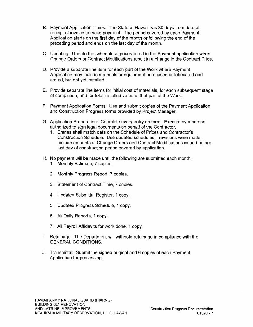
B. Payment Application Times: The State of Hawaii has 30 days from date of receipt of invoice to make payment. The period covered by each Payment Application starts on the first day of the month or following the end of the preceding period and ends on the last day of the month.
C. Updating: Update the schedule of prices listed in the Payment application when Change Orders or Contract Modifications result in a change in the Contract Price.
D. Provide a separate line item for each part of the Work where Payment Application may include materials or equipment purchased or fabricated and stored, but not yet installed.
E. Provide separate line items for initial cost of materials, for each subsequent stage of completion, and for total installed value of that part of the Work.
F. Payment Application Forms: Use and submit copies of the Payment Application and Construction Progress forms provided by Project Manager.
G. Application Preparation: Complete every entry on form. Execute by a person authorized to sign legal documents on behalf of the Contractor. 1. Entries shall match data on the Schedule of Prices and Contractor's
Construction Schedule. Use updated schedules if revisions were made. Include amounts of Change Orders and Contract Modifications issued before last day of construction period covered by application.
H. No payment will be made until the following are submitted each month: 1. Monthly Estimate, 7 copies.
2. Monthly Progress Report, 7 copies.
3. Statement of Contract Time, 7 copies.
4. Updated Submittal Register, I copy.
5. Updated Progress Schedule, I copy.
6. All Daily Reports, I copy.
7. All Payroll Affidavits for work done, I copy.
1. Retainage: The Department will withhold retainage in compliance with the GENERAL CONDITIONS.
J. Transmittal: Submit the signed original and 6 copies of each Payment Application for processing.
HAWAII ARMY NATIONAL GUARD (HIARNG) BUILDING 621 RENOVATION AND LATRINE IMPROVEMENTS
Construction Progress Documentation
KEAUKAHA MILITARY RESERVATION, HILO, HAWAII
01320-7

2.05 CONTRACTOR DAILY PROGRESS REPORTS A. The General Contractor and all Subcontractors shall keep a daily report of report
events.
B. The form of the Contractor Daily Progress Report shall be as directed by the Project Manager.
C. Submit copies of the previous week's reports on Monday morning at 10:00 a.m.
D. Submit copies of the reports with the monthly payment request for the whole period since the last payment request submittal.
E. Deliver the reports in hard copy, by e-mail, or web based construction management as directed by the Project Manager.
PART 3- EXECUTION (Not Used)
END OF SECTION
HAWAII ARMY NATIONAL GUARD (HIARNG) BUILDING 621 RENOVATION AND LATRINE IMPROVEMENTS
Construction Progress Documentation
KEAUKAHA MILITARY RESERVATION, HILO, HAWAII
01320-8
SECTION 01330 - SUBMITTAL PROCEDURES
PART I GENERAL
1.01 SUMMARY A. Comply with the GENERAL CONDITIONS "Shop Drawings and Other
Submittals" section and "Material Samples" section.
B. This Section includes administrative and procedural requirements for submitting Shop Drawings, Product Data, Samples, and other miscellaneous submittals.
C. Related Sections include the following: 1. SECTION 01320 - CONSTRUCTION PROGRESS DOCUMENTATION for
submitting schedules and reports, including Contractor's Construction Schedule and the Submittals Schedule.
2. SECTION 01770 - CLOSEOUT PROCEDURES for submitting warranties, project record documents and operation and maintenance manuals.
1.02 SUBMITTAL PROCEDURES A. Coordinate Work and Submittals: Contractor shall certify the submittals were
reviewed and coordinated.
B. Submittal Certification: Provide in MS Word when submitting electronically. Project Manager will provide an electronic copy of the Submittal Certification. Provide a reproduction (or stamp) of the "Submittal Certification" and furnish the required information with all submittals. Include the certification on: 1. The title sheet of each shop drawing, or on
2. The cover sheet of submittals in 8-1/2 inch x 11-inch format, or on
3. One face of a cardstock tag (minimum size 3-inch x 6-inch) tied to each sample. On the sample tag, identify the sample to ensure sample can be matched to the tag if accidentally separated. The opposite face of the tag will be used by the Project Manager to receive, review, log stamp and include comments.
C. Variances: The Contractor shall request approval for a variance. Clearly note any proposed deviations or variances from the Specifications, Drawings, and other Contract Documents on the submittal and also in a separately written letter accompanying the submittal.
HAWAII ARMY NATIONAL GUARD (HIARNG) BUILDING 621 RENOVATION AND LATRINE IMPROVEMENTS
Submittal Procedures
KEAUKAHA MILITARY RESERVATION, HILO, HAWAII
01330-1

D. Submittal Certification Form (stamp or digital)
CONTRACTOR'S NAME:
PROJECT:
As the General Contractor, we checked this submittal and we certify it is correct, complete, and in compliance with Contract Drawings and Specifications. All affected Contractors and suppliers are aware of, and will integrate this submittal into their own work.
SUBMITTAL NUMBER DATE RECEIVED
REVISION NUMBER DATE RECEIVED
SPECIFICATION SECTION NUMBER /PARAGRAPH NUMBER
DRAWING NUMBER
SUBCONTRACTOR'S NAME
SUPPLIER'S NAME
MANUFACTURER'S NAME
NOTE: DEVIATIONS FROM THE CONTRACT DOCUMENTS ARE PROPOSED AS FOLLOWS (Indicate "NONE" if there are no deviations)
CERTIFIED BY
PART 2 PRODUCTS (Not Used)
PART 3- EXECUTION
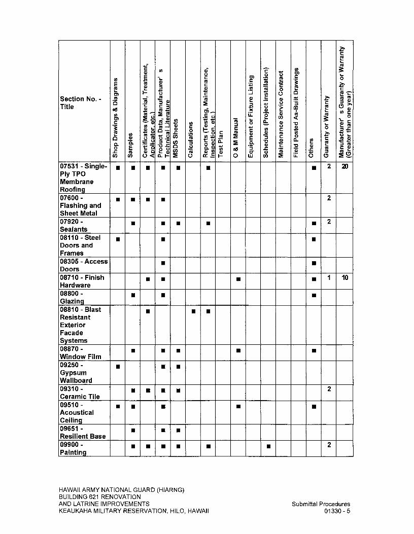
3.01 SUBMITTAL REGISTER AND TRANSMITTAL FORM A. Contractor shall use submittal register and transmittal forms as directed by the
Project Manager.
B. The listing of required submittals within this Section is provided for the Contractor's convenience. Review the specification technical sections and prepare a comprehensive listing of required submittals. Furnish submittals to the Project Manager for review.
C. Contractor shall separate each submittal item by listing all submittals in the following groups with the items in each group sequentially listed by the specification section they come from: 1. Administrative 2. Data 3. Tests 4. Closing
D. Contractor shall separate all different types of data as separate line items all with the column requirements.
HAWAII ARMY NATIONAL GUARD (HIARNG) BUILDING 621 RENOVATION AND LATRINE IMPROVEMENTS
Submittal Procedures
KEAUKAHA MILITAI3Y RESERVATION, HILO, HAWAII
01330-2

E. Contractor shall send monthly updates and reconciled copies electronically to the Project Manager and the Design Consultant in MS Word or MS Excel or other format as accepted by the Project Manager.
Section No. - Title
Sho
p D
raw
ings
& D
iagr
ams
Sam
ples
Cer
tific
ate
s (M
ateri
al, T
rea
tment
, A
pplic
ato
r, e
tc.)
P
roduc
t D
ata,
Man
ufac
ture
r' s
T
ech
nica
l Lite
ratu
re
MS
DS
She
ets
Cal
cula
tions
Rep
ort
s (T
esti
ng, M
ain
tena
nce,
In
spec
tion, e
tc.)
T
est
Pla
n
0 & M
Man
ual
Equ
ipm
ent
or
Fix
ture
Lis
tin
g
Sch
edu
les
(Pro
ject
Inst
alla
tion)
Mai
nten
ance
Serv
ice
Cont
ract
Fie
ld P
osted As-
Bui
lt D
raw
ings
Oth
ers
Gua
rant
y or
War
rant
y
Man
ufa
ctu
rer' s
Gua
rant
y or
Wa
rrant
y (G
reat
er
than
one
yea
r)
01320-Construction Progress Documenta-tion 01330-Submittal Procedures 01500-Temporary Facilities and Controls 01524- Construction Waste Management
• •
01700-Execution Requirements 01770- Closeout Procedures
• • •
02070-Selective Demolition 02220 - Site Demolition 02230-Site Clearing
• •
02287- Termite Control Barrier System
• • • • • 1 10
02300-Earthwork
HAWAII ARMY NATIONAL GUARD (HIARNG) BUILDING 621 RENOVATION AND LATRINE IMPROVEMENTS
Submittal Procedures
KEAUKAHA MILITARY RESERVATION, HILO, HAWAII
01330-3

Section No. - Title
Sho
p D
raw
ings
& D
iagr
ams
Sam
ple
s
Cer
tific
ates
(M
ateri
al, T
rea
tment
, A
pp
licat
or.
etc
.)
Pro
du
ct D
ata,
Ma
nuf
actu
rer' s
T
ech
nica
l Lite
ratu
re
MS
DS
She
ets
Cal
cula
tions
Rep
ort
s (T
esti
ng, M
ain
tena
nce,
In
spec
tion. e
tc.)
T
est
Pla
n
0 & M
Man
ual
Equ
ipm
ent
or
Fix
ture
Lis
tin
g
Sch
edu
les
(Pro
ject
Inst
alla
tion)
Mai
nten
ance
Serv
ice
Cont
ract
Fie
ld P
oste
d A
s-B
uilt D
raw
ings
Oth
ers
Gua
rant
y or
Wa
rrant
y
Man
ufac
ture
r' s
Gua
rant
y or
Warr
ant
y (G
reat
er
than
one
yea
r)
02361- Termite Control
• • • 2
02530 - Sewer System 02600-Drainage System 02740- Asphalt Concrete Paving
• u
02750-Portland Cement 02760 - Post Signage 02900- Planting
• • •
03300-Cast-in-Place Concrete 04810-Unit Masonry Assemblies
• • • •
05500 - Metal Fabrications
•
06100-Rough Carpentry 06200-Finish Carpentry
• • • • •
06311- Preservative Treated Lumber
• • • 2,5
07191- Concrete Sealer
u •
HAWAII ARMY NATIONAL GUARD (HIARNG) BUILDING 621 RENOVATION AND LATRINE IMPROVEMENTS
Submittal Procedures
KEAUKAHA MILITARY RESERVATION, HILO, HAWAII
01330-4
Section No. - Title
Sho
p D
raw
ings
& D
iagr
ams
Sam
ple
s
Cer
tific
ate
s (M
ateri
al, T
reat
men
t,
App
licat
or.
etc
.)
Pro
duc
t Dat
a, M
anuf
actu
rer' s
T
ech
nica
l Lite
ratu
re
MS
DS
She
ets
Cal
cula
tion
s
Rep
ort
s (T
esti
ng, M
ain
tena
nce,
In
spec
tio
n. e
tc.)
T
est
Pla
n
C
0 Equ
ipm
ent
or
Fix
ture
Lis
tin
g
Sch
edu
les
(Pro
ject
Inst
alla
tion
)
Mai
nte
nanc
e S
erv
ice
Con
trac
t
Fie
ld P
oste
d A
s-B
uilt D
raw
ings
Oth
ers
Gua
rant
y or
Wa
rrant
y
Man
ufac
ture
r' s
Gua
rant
y or W
arr
ant
y (G
reat
er
than
one
yea
r)
07531-Single- Ply TPO Membrane Roofing
• • • • • • 2 20
07600- Flashing and Sheet Metal
• • • • 2
07920- Sealants
• • 2
08110-Steel Doors and Frames
•
08305 - Access Doors 08710-Finish Hardware
• • • 1 10
08800-Glazing 08810-Blast Resistant Exterior Facade Systems
•
08870- Window Film
• • 09250- Gypsum Wallboard
•
09310- Ceramic Tile
• • • • 2
09510-Acoustical Ceiling 09651- Resilient Base
• • 09900- Painting
• • • 2
HAWAII ARMY NATIONAL GUARD (HIARNG) BUILDING 621 RENOVATION AND LATRINE IMPROVEMENTS
Submittal Procedures
KEAUKAHA MILITARY RESERVATION, HILO, HAWAII
01330-5

Section No. - Title
Sho
p D
raw
ings
& D
iagr
ams
Sam
ples
Cer
tific
ates
(M
ateria
l, Tr
eatm
ent,
A
pplic
ato
r, e
tc.)
P
rodu
ct D
ata,
Man
ufac
ture
r' s
Te
chni
cal L
itera
ture
M
SD
S She
ets
Cal
cula
tion
s
Rep
orts
(Te
stin
g, M
ain
tena
nce,
In
spec
tion
, etc
.)
Test
Pla
n
0 & M
Ma
nual
Equ
ipm
ent o
r Fix
ture
Lis
ting
Sch
edul
es (
Pro
ject
Inst
alla
tion)
Mai
nten
ance
Ser
vice
Con
trac
t
Fiel
d P
osted As-
Bui
lt D
raw
ings
Oth
ers
Gua
rant
y or W
arra
nty
Man
ufac
ture
r' s G
uara
nty
or W
arra
nty
(Gre
ater
tha
n o
ne y
ear)
10161-Solid Color Phenolic Toilet Partitions and Urinal Screens
• • •
10440- Signage
• • 10520-Fire Extinguishers and Cabinets
• • • 10800-Toilet Accessories 13282-Lead and Arsenic in Construction 13286-Handling of Lighting Ballasts and Lamps Containing PCBs and Mercury 13850-Fire Alarm Systems
• • • 15000- General Mechanical Requirements
. . . . . . I I I
15070-Mechanical Sound, Vibration, and Seismic Control 15080-Mechanical Insulation
HAWAII ARMY NATIONAL GUARD (HIARNG) BUILDING 621 RENOVATION AND LATRINE IMPROVEMENTS
Submittal Procedures
KEAUKAHA MILITARY RESERVATION, HILO, HAWAII
01330-6

Section No. - Title
Sh
op
Dra
win
gs &
Dia
gram
s
Cl) C, 0. E CC
Cl) Cer
tific
ates
(Mat
eri
al, T
rea
tment
, A
pp
licato
r, e
tc.)
P
rod
uct
Dat
a, M
an
ufact
ure
r' s
T
echnic
al L
itera
ture
M
SD
S S
heet
s
Calc
ula
tions
Repo
rts
(Tes
tin
g, M
ain
tenance
, In
spe
ctio
n. e
tc.)
T
est
Pla
n
0 & M
Ma
nua
l
Equ
ipm
ent
or
Fix
ture
Lis
ting
Sch
edu
les (
Pro
ject
Inst
alla
tion
)
Mai
nte
nan
ce S
erv
ice
Co
ntra
ct
Fie
ld P
ost
ed
As-
Bui
lt D
raw
ings
Oth
ers
Gua
rant
y or
Wa
rrant
y
Man
ufact
ure
r' s
Gua
rant
y or
Wa
rrant
y (G
reat
er
than o
ne
yea
r)
15300-Wet Pipe Fire Sprinkler Systems
0 0 0 • • E • •
15400- Plumbing
0• •
15720-Air Handling Equipment
0 • • •
15730-Unitar- y Air Condition-ing Equipment
• • • • • •
15810- Ductwork and Ductwork Accessories
• • • • • • •
15950-HVAC Testing/Adjust -ing/Balancing 16011-General Electrical Requirements 16100-Interior Electrical Work
•
16302- Electrical Site Work
• •
16510-Interior Lighting
• 5
16520- Exterior Lighting
• • 5
HAWAII ARMY NATIONAL GUARD (HIARNG) BUILDING 621 RENOVATION AND LATRINE IMPROVEMENTS
Submittal Procedures
KEAUKAHA MILITARY RESERVATION, HILO, HAWAII
01330-7

Section No. - Title
Sho
p D
raw
ings
& D
iagr
ams
Sam
ple
s
Cer
tific
ate
s (M
ateri
al, T
reat
ment
, A
pp
licat
or,
etc
.)
Pro
du
ct D
ata,
Ma
nuf
actu
rer' s
T
echni
cal L
itera
ture
M
SD
S S
heet
s
Cal
culatio
ns
Rep
ort
s (T
esti
ng, M
ain
tena
nce,
In
spec
tion, e
tc.)
T
est P
lan
0 & M
Man
ual
Equ
ipm
ent
or
Fix
ture
Lis
tin
g
Sch
edu
les
(Pro
ject
Inst
alla
tion)
Mai
nte
nanc
e S
ervi
ce C
ontr
act
Fie
ld P
oste
d A
s-B
uilt D
raw
ings
Oth
ers
Gua
rant
y or
War
rant
y
Man
ufac
ture
r' s
Gua
rant
y or
War
rant
y (G
reat
er
than
one
yea
r)
16710- Building Telecommuni-cations Cabling System
u • • 2 20
END OF SECTION
HAWAII ARMY NATIONAL GUARD (HIARNG) BUILDING 621 RENOVATION AND LATRINE IMPROVEMENTS
Submittal Procedures
KEAUKAHA MILITARY RESERVATION, HILO, HAWAII
01330-8
SECTION 01500 - TEMPORARY FACILITIES AND CONTROLS
PART I GENERAL
1.01 SUMMARY A. Requirements for temporary facilities and controls, including temporary utilities,
support facilities, and security and protection facilities.
B. Temporary utilities include but are not limited to, the following: 1. Sewers.
2. Storm drainage.
3. Water service and distribution.
4. Sanitary facilities, including toilets, wash facilities, and drinking water facilities.
5. Ventilation.
6. Electric power service.
7. Lighting.
8. Telephone service.
C. Support facilities include, but are not limited to, the following: 1. Project signs.
2. Storage and fabrication sheds.
3. Trash, refuse disposal.
4. Temporary roads and paving.
5. Erosion controls and site drainage.
D. Security and protection facilities and measures include, but are not limited to, the following: 1. Environmental protection.
2. Stormwater control.
3. Tree and plant protection.
4. Site enclosure fence.
5. Barricades, warning signs, and lights.
HAWAII ARMY NATIONAL GUARD (HIARNG) BUILDING 621 RENOVATION AND LATRINE IMPROVEMENTS
Temporary Facilities and Controls
KEAUKAHA MILITARY RESERVATION, HILO, HAWAII
01500-1

6. Pest control.
7. Fire protection.
E. Related Sections: Refer to Divisions 2 through 16 for other temporary requirements including ventilation, humidity requirements and products in those Sections.
1.02 USE CHARGES A. General: Cost or use charges for temporary facilities are not chargeable to the
State and shall be included in the Contract Price. Allow other entities to use temporary services and facilities without cost, including, but not limited to, the following: 1. Other Contractors with agreements with the State or Federal Government
working within the contract limits.
2. Occupants of Project.
3. Testing agencies.
4. Project Manager and personnel of authorities having jurisdiction.
1.03 SUBMITTALS A. Temporary Utility Reports: Submit reports of tests, inspections, meter readings,
and similar procedures performed on temporary utilities.
B. Landfill Disposal Receipts: Submit copies of receipts issued by a landfill facility. Include receipts with Contractor Daily Progress Report.
1.04 QUALITY ASSURANCE A. Standards: Comply with IBC Chapter 33, "Safeguards During Construction",
ANSI A10.6, "Safety Requirements for Demolition Operations", NECA's "Temporary Electrical Facilities", and NFPA 241, "Construction, Alteration, and Demolition Operations". I. Trade Jurisdictions: Assigned responsibilities for installation and operation of
temporary utilities are not intended to interfere with trade regulations and union jurisdictions.
2. Electrical Service: Comply with NECA, NEMA, and UL standards and regulations for temporary electric service. Install service to comply with NFPA 70, "National Electrical Code". a. Tests and Inspections: Arrange for authorities having jurisdiction to test
and inspect each temporary utility before use. Obtain required certifications and permits.
HAWAII ARMY NATIONAL GUARD (HIARNG) BUILDING 621 RENOVATION AND LATRINE IMPROVEMENTS
Temporary Facilities and Controls
KEAUKAHA MILITARY RESERVATION, H1LO, HAWAII
01500-2
1.05 PROJECT CONDITIONS A. Temporary Utilities: At earliest feasible time, when acceptable to the Project
Manager, change over from use of temporary service to use of permanent service. 1. Temporary Use of Permanent Facilities: Installer of each permanent service
shall assume responsibility for operation, maintenance, and protection of each permanent service during its use as a construction facility before Project Manager's acceptance, regardless of previously assigned responsibilities.
B. Conditions of Use: The following conditions apply to use of temporary services and facilities by all parties engaged in the Work: 1. Keep temporary services and facilities clean and neat.
2. Relocate temporary services and facilities as required by progress of the Work.
1.06 PREPARATION AND PROTECTION A. Protection-of Property: Continually maintain adequate protection of the Work
from damage and protect all property, including but not limited to buildings, equipment, furniture, grounds, vegetation, material, utility systems located at and adjoining the job site. Repair, replace or pay the expense to repair damages resulting from Contractor's fault or negligence.
B. Before starting work to be applied to previously erected constructions, make a thorough and complete investigation of the recipient surfaces and determine their suitability to receive required additional construction and finishes. Make any repair that is required to properly prepare surfaces, and coordinate the Work to provide a suitable surface to receive following Work.
C. Commencing work by any trade implies acceptance of existing conditions and surfaces as satisfactory for the application of subsequent work, and full responsibility for finished results and assumption of warranty obligations under the Contract.
D. Protect existing (including interiors) work to prevent damage by vandals or the elements. Provide temporary protection. Use curtains, barricades, or other appropriate methods. Take positive measures to prevent breakage of glass and damage to plastic, aluminum and other finishes.
E. Repairs and Replacements: Promptly replace and repair damages to the approval of the Project Manager. Additional time required to secure replacements and to make repairs does not justify a time extension.
PART 2 PRODUCTS
2.01 MATERIALS A. General: Provide new materials. Undamaged, previously used materials in
serviceable condition may be used if approved by Project Manager. Provide materials suitable for use intended.
HAWAII ARMY NATIONAL GUARD (HIARNG) BUILDING 621 RENOVATION AND LATRINE IMPROVEMENTS
Temporary Facilities and Controls
KEAUKAHA MILITARY RESERVATION, H1LO, HAWAII
01500-3

B. Plastic Enclosure Fence: Industry standard 4-feet high plastic fencing with metal (or wood) post supports at 10-feet on center connected with a top and bottom 12-gauge soft annealed galvanized tie wires securely connected to posts. Posts shall be capable of resisting a lateral load of 100 pounds measured at the top of the post.
C. Paint: Comply with requirements in SECTION 09900 - PAINTING.
D. Water: Potable.
2.02 EQUIPMENT A. Fire Extinguishers: Hand carried, portable, UL rated. Provide class and
extinguishing agent as indicated or a combination of extinguishers of NFPA recommended classes for exposures. Comply with NFPA 10 and NFPA 241 for classification, extinguishing agent, and size required by location and class of fire exposure.
B. Self Contained Combination Toilet and Urinal Units: Single occupant units of chemical, aerated recirculation, or combustion type; vented; fully enclosed with a glass fiber reinforced polyester shell or similar nonabsorbent material. One quarter of, or at least one unit(s) shall contain a handwash sink with potable water storage.
C. Drinking Water Fixtures: Drinking water fountains or containerized, tap dispenser, bottled water drinking water units, or water cooler dispensing water at 45- 55 degree F available at Field Office(s) including paper cup supply.
D. Electrical Outlets: Properly configured, NEMA polarized outlets to prevent insertion of 110 to 120 V plugs into higher voltage outlets; equipped with ground fault circuit interrupters, reset button, and pilot light.
E. Power Distribution System Circuits: Where permitted and overhead and exposed for surveillance, wiring circuits, not exceeding 125 V ac, 20 A rating, and lighting circuits may be nonmetallic sheathed cable.
F. Data and Communication: Provide service and equipment throughout construction period. 1. Provide a facsimile machine at Contractor' field office.
2. Provide plain paper copier, automatic feed, collating capabilities and printing up to 11-inch by 17-inch sheets at Contractor' field office.
3. Computer Internet Connection: Provide a high-speed connection (landline satellite or wireless). Connection shall be separate from the telephone service.
HAWAII ARMY NATIONAL GUARD (HIARNG) BUILDING 621 RENOVATION AND LATRINE IMPROVEMENTS
Temporary Facilities and Controls
KEAUKAHA MILITARY RESERVATION, HILO, HAWAII
01500-4

PART 3- EXECUTION
3.01 INSTALLATION, GENERAL A. Locate facilities where they will serve Project adequately and result in minimum
interference with performance of the Work. Relocate and modify facilities as required.
B. Provide each facility ready for use when needed to avoid delay. Maintain and modify as required. Do not remove until facilities are no longer needed or are replaced by authorized use of completed permanent facilities.
3.02 TEMPORARY UTILITY INSTALLATION A. General: Engage appropriate local utility company to install temporary service or
connect to existing service where directed by the Project Manager. Where utility company provides only part of the service, provide the remainder with matching, compatible materials and equipment. Comply with utility company recommendations. 1. Arrange with utility company, the Department, and existing users for time
when service can be interrupted, if necessary, to make connections for temporary services.
2. Provide adequate capacity at each stage of construction. Before temporary utility is available, provide trucked in services.
B. Storm and Sewer Drainage: If sewers are available, provide temporary connections to remove effluent that can be discharged lawfully. If storm drains are not available or cannot be used, provide drainage ditches, dry wells, stabilization ponds, and similar facilities. If neither sewers nor drainage facilities can be lawfully used for discharge of effluent, provide containers to remove and dispose of effluent off site in a lawful manner. 1. Filter out excessive soil, construction debris, chemicals, oils, and similar
contaminants that might clog sewers, storm drains or pollute waterways before discharge.
2. Connect temporary sewers, if used as directed by sewer department officials.
3. Maintain temporary sewers and drainage facilities in a clean, sanitary condition. After heavy use, restore normal conditions promptly.
4. Provide temporary filter beds, settlement tanks, separators, and similar devices to purify effluent to levels acceptable to authorities having jurisdiction.
C. Water Service: Make arrangements with the utility company for temporary use of water, and pay for all expenses. However, at the option of the Contractor, a temporary tap into the facility's existing water system is allowed, subject to the following conditions: 1. Comply with the Department of Health's and County water provider's
requirements when tapping into the existing water system.
HAWAII ARMY NATIONAL GUARD (HIARNG) BUILDING 621 RENOVATION AND LATRINE IMPROVEMENTS
Temporary Facilities and Controls
KEAUKAHA MILITARY RESERVATION, HILO, HAWAII
01500-5

2. Meter the tapped line and prior to water use, notify the Project Manager to observe an initial meter reading.
3. Take monthly meter readings. Pay the State, on a monthly basis, for water used at the current rate per 1,000 gallons.
4. Payments are to be by check as directed by the Project Manager:
5. Checks shall be accompanied by the following information: a. Name of facility, Project Name and Title and State Job No.
b. Contractor's name.
c. Initial meter reading for the month and final meter reading for the month.
d. Volume of water used and the amount due in payment for that water.
6. Upon completion of the project and just prior to removal of the water meter, notify the Project Manager to observe a final meter reading.
7. Should the Contractor at any time fail to comply with any or all of the above conditions, the Department may terminate the use of water. The Contractor shall remove the hookup within 48 hours of notification of such termination.
D. Sanitary Facilities: Provide temporary toilets, wash facilities, and drinking water fixtures. Comply with regulations and health codes for type, number, location, operation, and maintenance of fixtures and facilities. 1. Disposable Supplies: Provide toilet tissue, paper towels, paper cups, and
similar disposable materials for each facility. Maintain adequate supply. Provide covered waste containers for disposal of used material.
2. Toilets: Install self contained toilet units. Shield toilets to ensure privacy. Provide separate facilities for male and female personnel.
3. Wash Facilities: Install wash facilities supplied with potable water at convenient locations for personnel who handle materials that require wash up. Dispose of drainage properly. Supply cleaning compounds appropriate for each type of material handled. a. Provide safety showers, eyewash fountains, and similar facilities for
convenience, safety, and sanitation of personnel.
4. Locate toilets and drinking water fixtures so personnel need not walk more than 200-feet horizontally to facilities.
E. Ventilation and Humidity Control: Provide temporary ventilation required by construction activities for curing or drying of completed installations or for protecting installed construction from adverse effects of high humidity. Select equipment that will not have a harmful effect on completed installations or elements being installed. Coordinate ventilation requirements to produce ambient condition required and minimize energy consumption.
HAWAII ARMY NATIONAL GUARD (HIARNG) BUILDING 621 RENOVATION AND LATRINE IMPROVEMENTS
Temporary Facilities and Controls
KEAUKAHA MILITARY RESERVATION, HILO, HAWAII
01500-6

F. Electric Power Service: Provide weatherproof, grounded electric power service and distribution system of sufficient size, capacity, and power characteristics during construction period. Include meters, transformers, overload protected disconnecting means, automatic ground fault interrupters, and main distribution switchgear. Use of State facilities electrical power services will be permitted as long as equipment is maintained in a condition acceptable to the Project Manager. Make arrangements with utility companies for temporary use of electricity for construction use. Pay for all expenses pertaining thereto.
G. Electrical Distribution: Provide receptacle outlets adequate for connection of power tools and equipment. Protect wiring, in conduits or other, measures when exposed to possible damage or traffic areas.
H. Lighting: Provide temporary lighting with local switching that provides adequate illumination for construction operations and traffic conditions.
I. Telephone Service: Provide temporary telephone service throughout construction period for common use facilities used by all personnel engaged in construction activities. Install separate telephone line for the Contractor's field office and first aid station. 1. At field office, provide land-line telephone service or if approved by the
Project Manager, wireless (digital or cellular) telephone service. Provide internet service with ISP with unlimited access. Provide broadband where available.
2. At each telephone, post a list of important telephone numbers. a. Police and fire departments,
b. Ambulance service,
c. Contractor's home office,
d. Contract contacts, 1) Subcontractors
2) Suppliers
e. Department Staff contacts, 1) Construction Coordinator
2) Inspector
f. State's Emergency contacts, 1) Construction Coordinator after hours
2) Inspector after hours
g. Principal Subcontractors' field and home offices,
h. User's office and emergency.
HAWAII ARMY NATIONAL GUARD (HIARNG) BUILDING 621 RENOVATION AND LATRINE IMPROVEMENTS
Temporary Facilities and Controls
KEAUKAHA MILITARY RESERVATION, HILO, HAWAII
01500-7
3. Provide a portable wireless telephone with voice-mail or messaging service for superintendent's use in making and receiving telephone calls when away from field office.
3.03 SUPPORT FACILITIES INSTALLATION A. General: Comply with the following:
1. Locate field offices, storage sheds, sanitary facilities, and other temporary construction and support facilities for easy access or where shown on Contract Drawings or as directed by the Project Manager.
2. Maintain support facilities until near Substantial Completion. Remove before Substantial Completion.
B. Traffic Controls: Provide temporary traffic controls at junction of temporary roads with public roads. Include warning signs for public traffic and "STOP" signs for entrance onto public roads. Comply with requirements of authorities having jurisdiction.
C. Site Drainage: 1. Dispose of rainwater in a lawful manner that will not result in flooding Project
or adjoining property nor endanger permanent Work or temporary facilities.
2. Before connection and operation of permanent drainage piping system, provide temporary drainage where roofing or similar waterproof deck construction is completed.
D. Project Sign and Temporary Sign(s): 1. Provide and install project identification sign and other signs as listed.
a. Project Sign: As indicated in Drawings.
b. Warning Sign: Attached to PART 3 - EXECUTION of this Section.
2. Install signs where directed by the Project Manager or where indicated to inform public and persons seeking entrance to the Project. Do not permit installation of unauthorized signs.
3. Provide temporary signs to provide directional information to constructional personnel and visitors.
4. Construct signs with durable materials, properly supported or mounted, and visible.
E. Trash, Refuse Disposal: 1. Department of Health - Illegal Dumping Notice. See attachment to Part 3 of
this section. a. This Notice to be printed out on 8.5x1 1" paper.
b. This Notice to be posted at the job site field office and/or in locations visible to all contractors, subcontractors, suppliers, vendors, etc. throughout the duration of the project.
HAWAII ARMY NATIONAL GUARD (HIARNG) BUILDING 621 RENOVATION AND LATRINE IMPROVEMENTS
Temporary Facilities and Controls
KEAUKAHA MILITARY RESERVATION, HILO, HAWAII
01500-8

2. Illegal Dumping of solid waste could subject the Contractor to fines and could lead to felony prosecution in accordance with Chapter 342H, HRS. For more information, see the following web site: htt*://www.hawaii. • ov/health/environmental/waste/sw/ e df/lIldum.. e df
3. Provide waste collection containers in sizes adequate to handle waste from construction operations. Containerize and clearly label hazardous, dangerous, or unsanitary waste materials separately from other waste.
4. Do not burn debris or waste materials on the project site.
5. Do not bury debris or waste material on the project site unless specifically allowed elsewhere in these specifications as backfill material.
6. Haul unusable debris and waste material to an appropriate off site dump area. a. Water down debris and waste materials during loading operations or
provide other measures to prevent dust or other airborne contaminants.
b. Vacuum, wet mop, or damp sweep when cleaning rubbish and fines which can become airborne from floors or other paved areas. Do not dry sweep.
C. Use enclosed chutes or containers to conveying debris from above the ground floor level.
7. Clean up shall include the collection of all waste paper and wrapping materials, cans, bottles, construction waste materials and other objectionable materials, and removal as required. Frequency of clean up shall coincide with rubbish producing events.
F. Janitorial Services: Provide janitorial services on a weekly basis for the Project Manager's field office, first aid stations, toilets, wash facilities, lunchrooms, and similar areas.
3.04 ENVIRONMENTAL CONTROLS A. General: Provide protection, operate temporary facilities, and conduct
construction in ways and by methods that comply with environmental regulations and that minimize possible air, waterway, and subsoil contamination or pollution or other undesirable effects.
B. Dust Control: 1. Prevent dust from becoming airborne at all times including non working
hours, weekends and holidays in conformance with the State Department of Health, Administrative Rules, Title 11, Chapter 60.1 Air Pollution Control.
2. Contractor is responsible for and shall determine the method of dust control. Subject to the Contractor's choice, the use of water or environmentally friendly chemicals may be used over surfaces that create airborne dust.
HAWAII ARMY NATIONAL GUARD (HIARNG) BUILDING 621 RENOVATION AND LATRINE IMPROVEMENTS
Temporary Facilities and Controls
KEAUKAHA MILITARY RESERVATION, H1LO, HAWAII
01500-9

3. Contractor is responsible for all damage claims due to their negligence to control dust.
C. Noise Control: 1. Keep noise within acceptable levels at all times in conformance with the State
Department of Health, Administrative Rules, Title 11, Chapter 46 Community Noise Control. Obtain and pay for the Community Noise Permit when construction equipment or other devices emit noise at levels exceeding the allowable limits.
2. Ensure mufflers and other devices are provided on equipment, internal combustion engines and compressors to reduce loud disruptive noise levels and maintain equipment to reduce noise to acceptable levels.
3. Unless specified elsewhere, do not start construction equipment that meet allowable noise limits prior to 6:45 A.M. or equipment exceeding allowable noise levels prior to 7:00 A.M.
D. Erosion Control: 1. During grading operations, maintain the grade to prevent damage to adjoining
property from water and eroding soil.
2. install temporary berms, cut off ditches and other provisions needed for construction methods and operations. Should there be a question if the temporary measures are insufficient to prevent erosion, the Project Manager shall make the final determination.
3. Construct and maintain drainage outlets and silting basins where shown on the Drawings and when required to minimize erosion and pollution of waterways during construction.
E. Tree and Plant Protection: Install temporary fencing located as indicated or outside the drip line of trees to protect vegetation from construction damage. Protect existing landscaping and tree root systems from damage, flooding, and erosion due to construction activity.
3.05 VIOLATION OF ENVIRONMENTAL PROVISIONS A. Violations of any of the above environmental control requirements or any other
pollution control requirements; which may also be specified in the other Specifications sections, shall be resolved under the SUSPENSION and CORRECTIVE WORK Section of the GENERAL CONDITIONS.
3.06 BARRICADES AND ENCLOSURES A. Barricades: Before construction operations begin, erect temporary construction
barricade(s) to prevent unauthorized persons from entering the project area and to the extent required by the Project Manager. 1. Provide gates in sizes and at locations necessary to accommodate delivery
vehicles and other construction operations.
2. Maintain security by limiting number of keys and restricting distribution to authorized personnel. Provide Project Manager with 2 sets of keys.
HAWAII ARMY NATIONAL GUARD (HIARNG) BUILDING 621 RENOVATION AND LATRINE IMPROVEMENTS
Temporary Facilities and Controls
KEAUKAHA MILITARY RESERVATION, HILO, HAWAII
01500-10

3. Maintain temporary construction barricade(s) throughout the duration of the Work. During the course of the project, the Project Manager may require additional barricades be provided for the safety of the public. Contractor shall erect the additional barricade(s) at its own expense.
4. Construction: Plastic fencing.
B. Security Enclosure and Lockup: 1. Install substantial temporary enclosure around partially completed areas of
construction.
2. Provide lockable entrances to prevent unauthorized entrance, vandalism, theft, and similar violations of security.
C. Temporary Enclosures: 1. Provide temporary enclosures for protection of construction, in progress and
completed, from exposure, foul weather, other construction operations, and similar activities. Provide temporary weathertight enclosure for building exterior.
2. Where cooling is needed and permanent enclosure is not complete, provide insulated temporary enclosures. Coordinate enclosure with ventilating and material drying or curing requirements to avoid dangerous conditions and effects.
3.07 TEMPORARY FIRE PROTECTION A. Until fire protection needs are supplied by permanent facilities, install and
maintain temporary fire protection facilities of types needed to protect against reasonably predictable and controllable fire losses. Comply with NFPA 241. 1. Provide fire extinguishers, installed on walls on mounting brackets, visible
and accessible from space being served, with sign mounted above. a. Field Offices: Class A stored pressure water type extinguishers.
b. Other Locations: Class ABC dry chemical extinguishers or a combination of extinguishers of NFPA recommended classes for exposures.
c. Locate fire extinguishers where convenient and effective for their intended purpose; provide not less than one extinguisher on each floor.
2. Store combustible materials in containers in fire safe locations.
3. Maintain unobstructed access to fire extinguishers, fire hydrants, temporary fire protection facilities, stairways, and other access routes for firefighting. Prohibit smoking in hazardous fire exposure areas.
4. Supervise welding operations, combustion type temporary heating units, and similar sources of fire ignition.
HAWAII ARMY NATIONAL GUARD (HIARNG) BUILDING 621 RENOVATION AND LATRINE IMPROVEMENTS
Temporary Facilities and Controls
KEAUKAHA MILITARY RESERVATION, HILO, HAWAII
01500-11

5. Permanent Fire Protection: At earliest feasible date in each area of Project, complete installation of permanent fire protection facility, including connected services, and place into operation and use. Instruct key personnel on use of facilities.
6. Develop and supervise an overall fire prevention and first aid fire protection program for personnel at Project site. Review needs with local fire department and establish procedures to be followed. Instruct personnel in methods and procedures. Post warnings and information.
3.08 OPERATION, TERMINATION, AND REMOVAL A. Maintenance: Maintain facilities in good operating condition until removal.
Protect from damage caused by heat temperatures and similar elements.
B. Termination and Removal: Remove each temporary facility when need for its service has ended, or when it has been replaced by authorized use of a permanent facility, or no later than Substantial Completion. Complete or, if necessary, restore permanent construction that may have been delayed because of interference with temporary facility. Repair damaged Work, clean exposed surfaces, and replace construction that cannot be satisfactorily repaired. 1. Materials and facilities that constitute temporary facilities are the property of
Contractor. The Department reserves the right to take possession of Project identification signs.
3.09 ATTACHMENTS A. Warning Sign: Requirements for Warning Sign.
B. Department of Health - Illegal Dumping Notice.
END OF SECTION
HAWAII-ARMY NATIONAL GUARD (HIARNG) BUILDING 621 RENOVATION AND LATRINE IMPROVEMENTS
Temporary Facilities and Controls
KEAUKAHA MILITARY RESERVATION, HILO, HAWAII
01500-12

2
REQUIREMENTS FOR WARNING SIGN
[II
p .,........................... •. 911 I, 411
,. ... JO ... . ..
1.14° 0 HOLE (fYPICALFOR2) /
1/8"'MCKLEMMi.S 3/4 HIGH
1/24 RADIUS (TYPICAL) '-1/4" TIIICKLE1TERS, 1-112° HIGH
1. General Requirements: Furnish all labor, materials and equipments necessary to construct and install warning signs as specified hereinafter.
2. Materials a. Backing: Backing shall be 6061-T6 aluminum 0.032-inch minimum thick-
ness. b. Paint: Paint shall be satin finish, exterior grade or factory baked enamel
or a combination thereof. 3. Colors: Signs shall have white background. Remaining items shall be similar to
Rust-Oleum Federal Safety Red. 4.
Requirements for Warning Sign: Message configuration and dimensions shall be in accordance with the attached illustration.
5. Installation a. Signs shall be located at 50-foot intervals around roped off work area or
at all entrances in the case of interior work. b. Signs shall be attached to the rope barrier, rope barrier supports, individ-
ual sign supports or buildings. Do not use nails to attach signs to build ing(s).
6. Clean-up: Remove all signs upon completion of project. Repair any damages caused by sign mounting and removal.
HAWAII ARMY NATIONAL GUARD (HIARNG) BUILDING 621 RENOVATION AND LATRINE IMPROVEMENTS
Temporary Facilities and Controls
KEAUKAI-IA MILITARY RESERVATION, HILO, HAWAII
01500-13
2

DEPARTMENT OF I!-E.,A.L--,---,T'H- rILLE G AL; DG NOTil, ICE
Thelaw requires you to dispose soraste o nly at recyc; ing or dis osa! fa cilities
perm b y the Department of Health
"Solid waste'" includes municipal refuse, con~-
struction and demotition waste, household wwaste, s carbatttert*es, derelict vehicles,
gr een wastes, f-urniture, and aP piiances
Illegal dumping of solid waste or allowing illegal disposal of solid waste on
your property even If contractual or other a r ran g--..e-m, ents are m ade could subject ytou to.
from $i0,00 I to $25,000 per iccurrencefines and could lead to feb ty prosecU1,ution
in accordance with Chapter 342H,,, HRS%
Contact the Department of Health, Solid; W/aste Section at 5864226
to report illegal dumping activities or if you have fu rther questions
HAWAII ARMY NATIONAL GUARD (H1ARNG) BUILDING 621 RENOVATION AND LATRINE IMPROVEMENTS
Temporary Facilities and Controls
KEAUKAHA MILITARY RESERVATION, HILO, HAWAII
01500-14

SECTION 01524 - CONSTRUCTION WASTE MANAGEMENT
PART I - GENERAL
1.01 SUMMARY A. This Section includes administrative and procedural requirements for the
following: 1. Salvaging nonhazardous demolition and construction waste.
2. Recycling nonhazardous demolition and construction waste.
3. Disposing of nonhazardous demolition and construction waste.
B. Related Sections include the following: 1. SECTION 01500 - TEMPORARY FACILITIES AND CONTROLS for
environmental-protection measures during construction, and location of waste containers at Project site.
2. SECTION 02070 - SELECTIVE DEMOLITION for disposition of waste resulting from partial demolition of buildings, structures, and site improvements and for disposition of hazardous waste.
C. The State's goal is to apply sound environmental principles in the design, construction and use of facilities. As part of the implementation of that goal, the Contractor shall: 1. Practice efficient waste management when sizing, cutting, and installing
products and materials and S
2. Use all reasonable means to divert construction and demolition waste from landfills and incinerators and to facilitate their recycling or reuse.
1.02 DEFINITIONS A. Construction Waste: Building and site improvement materials and other solid
waste resulting from construction, remodeling, renovation, or repair operations. Construction waste includes packaging.
B. Demolition Waste: Building and site improvement materials resulting from demolition or selective demolition operations.
C. Disposal: Removal off-site of demolition and construction waste and subsequent sale, recycling, reuse, or deposit in landfill or incinerator acceptable to authorities having jurisdiction.
D. Recycle: Recovery of demolition or construction waste for subsequent processing in preparation for reuse.
E. Salvage: Recovery of demolition or construction waste and subsequent sale or reuse in another facility.
HAWAII ARMY NATIONAL GUARD (HIARNG) BUILDING 621 RENOVATION AND LATRINE IMPROVEMENTS
Construction Waste Management
KEAUKAHA MILITARY RESERVATION, HILO, HAWAII
01524-1

F. Salvage and Reuse: Recovery of demolition or construction waste and subsequent incorporation into the Work.
1.03 REFERENCES A. A Contractor's Waste Management Guide: Best Management Practices and
Tools for Job Site Recycling and Waste Reduction in Hawaii, 1999. Request a copy from the State of Hawaii, Clean Hawaii Center (808) 587-3802 or download from www.hawaii.gov/dbedt/ert/cwm-q/index.htmi.
B. Minimizing Construction & Demolition Waste. State of Hawaii, Department of Health guidance on construction and demolition (C&D) waste management and listing of permitted C&D waste management facilities. Download from www.state.hi.us/health/eh/shwb/sw.
1.04 PERFORMANCE REQUIREMENTS A. General: Develop waste management plan that results in end-of-Project rates for
salvage/recycling of 50 percent by weight of total waste generated by the Work.
B. Salvage/Recycle Requirements: State's requirement is to salvage and recycle as much nonhazardous demolition and construction waste as possible including the following materials: 1. Demolition Waste:
a. Green waste.
b. Asphaltic concrete paving.
c. Concrete.
d. Concrete reinforcing steel.
e. Brick.
f. Concrete masonry units.
g. Wood studs.
h. Wood joists.
i. Plywood and oriented strand board.
j. Wood paneling.
k. Wood trim.
I. Structural and miscellaneous steel.
m. Rough hardware.
n. Roofing.
o. Insulation.
HAWAII ARMY NATIONAL GUARD (HIARNG) BUILDING 621 RENOVATION AND LATRINE IMPROVEMENTS
Construction Waste Management
KEAUKAHA MILITARY RESERVATION, HILO, HAWAII
01524-2

p. Doors and frames.
q. Door hardware.
r. Windows.
s. Glazing.
t. Metal studs.
u. Gypsum board.
v. Acoustical tile and panels.
w. Carpet.
x. Carpet pad.
y. Demountable partitions.
z. Equipment.
aa. Cabinets.
bb. Plumbing fixtures.
cc. Piping.
dd. Supports and hangers.
ee. Valves.
ff. Sprinklers.
gg. Mechanical equipment.
hh. Refrigerants.
ii. Electrical conduit.
jj. Copper wiring.
kk. Lighting fixtures.
Il. Lamps.
mm. Ballasts.
nn. Electrical devices.
HAWAII ARMY NATIONAL GUARD (HIARNG) BUILDING 621 RENOVATION AND LATRINE IMPROVEMENTS
Construction Waste Management
KEAUKAHA MILITARY RESERVATION, HILO, HAWAII
01524-3

00. Switchgear and panelboards.
pp. Transformers.
2. Construction Waste: a. Site-clearing waste (including Green Waste, Soil, Rock).
b. Masonry and CMU.
c. Lumber.
d. Wood sheet materials.
e. Wood trim.
f. Metals.
g. Roofing.
h. Ipsulation.
i. Carpet and pad.
j. Gypsum board.
k. Piping.
I. Electrical conduit.
m. Packaging: Regardless of salvage/recycle goal indicated above, salvage or recycle 100 percent of the following uncontaminated packaging materials: 1) Paper.
2) Cardboard.
3) Boxes.
4) Plastic sheet and film.
5) Polystyrene packaging.
6) Wood crates.
7) Plastic pails.
1.05 SUBMITTALS A. Waste Management Plan: Submit 3 copies of plan within 30 days of date
established for the Notice to Proceed.
HAWAII ARMY NATIONAL GUARD (HIARNG) BUILDING 621 RENOVATION AND LATRINE IMPROVEMENTS
Construction Waste Management
KEAUKAHA MILITARY RESERVATION, HILO, HAWAII
01524-4
B. Waste Reduction Progress Reports: Concurrent with each Application for Payment, submit three copies of report. Include separate reports for demolition and construction waste. Failure to submit this report may render the Payment Application incomplete and delay payment. Include the following information (the Progress Reports may be submitted in a form similar to Table 2 of Appendix A): 1. Material category.
2. Generation point of waste.
3. Total quantity of waste in tons.
4. Quantity of waste salvaged, both estimated and actual in tons.
5. Quantity of waste recycled, both estimated and actual in tons.
6. Total quantity of waste recovered (salvaged plus recycled) in tons.
7. Total quantity of waste recovered (salvaged plus recycled) as a percentage of total waste.
8. Records (Donations, Sales, Recycling/Processing, Landfill/Incinerator) as described in the following paragraph).
C. Before request for Substantial Completion, submit: 1. Waste Reduction Calculations: Before request for Substantial Completion,
submit three copies of calculated end-of-Project rates for salvage, recycling, and disposal as a percentage of total waste generated by the Work. Fill out the actual quantities in Appendix A Table 2 WASTE REDUCTION WORK PLAN. Also include an actual Cost/Revenue analysis to be compared with the projected Cost/Revenue analysis of the Waste Management Plan (See Appendix A Table 3).
2. Records of Donations: Indicate receipt and acceptance of salvageable waste donated to individuals and organizations. Indicate whether organization is tax exempt.
3. Records of Sales: Indicate receipt and acceptance of salvageable waste sold to individuals and organizations. Indicate whether organization is tax exempt.
4. Recycling and Processing Facility Records: Indicate receipt and acceptance of recyclable waste by recycling and processing facilities licensed to accept them. Include manifests, weight tickets, receipts, and invoices.
5. Landfill and Incinerator Disposal Records: Indicate receipt and acceptance of waste by landfills and incinerator facilities licensed to accept them. Include manifests, weight tickets, receipts, and invoices.
D. Qualification Data: For Waste Management Coordinator and refrigerant recovery technician.
HAWAII ARMY NATIONAL GUARD (HIARNG) BUILDING 621 RENOVATION AND LATRINE IMPROVEMENTS
Construction Waste Management
KEAUKAHA MILITARY RESERVATION, HILO, HAWAII
01524-5

E. Statement of Refrigerant Recovery: Signed by refrigerant recovery technician responsible for recovering refrigerant, stating that all refrigerant that was present was recovered and that recovery was performed according to EPA regulations. Include name and address of technician and date refrigerant was recovered.
1.06 QUALITY ASSURANCE A. Waste Management Coordinator Qualifications: Submit qualifications of
individual designated as Waste Management Coordinator, including resume and past related projects.
B. Refrigerant Recovery Technician Qualifications: Certified by EPA-approved certification program.
C. Regulatory Requirements: Comply with hauling and disposal regulations of authorities having jurisdiction.
D. Waste Management Conference: Conduct conference at Project site to comply with requirements in SECTION 01310- PROJECT MANAGEMENT AND COORDINATION. Review methods and procedures related to waste management including, but not limited to, the following: 1. Review and discuss waste management plan including responsibilities of
Waste Management Coordinator.
2. Review requirements for documenting quantities of each type of waste and its disposition.
3. Review and finalize procedures for materials separation and verify availability of containers and bins needed to avoid delays.
4. Review procedures for periodic waste collection and transportation to recycling and disposal facilities.
5. Review waste management requirements for each subcontractor.
1.07 WASTE MANAGEMENT PLAN A. General: Develop plan consisting of waste identification, waste reduction work
plan, and cost/revenue analysis. Use the plan included in Appendix A of this section and fill out the appropriate items. Include separate sections in plan for demolition and construction waste. Indicate quantities by weight or volume, but use same units of measure throughout waste management plan.
B. Waste Management Coordinator: Indicate name of individual(s) to be responsible for implementing, monitoring, and reporting status of waste management plan.
C. Waste Identification: Fill out Table I of Appendix A. Indicate anticipated types and quantities of demolition, site-clearing, and construction waste generated by the Work. Include estimated quantities and assumptions for estimates.
HAWAII ARMY NATIONAL GUARD (HIARNG) BUILDING 621 RENOVATION AND LATRINE IMPROVEMENTS
Construction Waste Management
KEAUKAHA MILITARY RESERVATION, HILO, HAWAII
01524-6

D. Waste Reduction Work Plan: Fill out the estimated quantities in Table 2 of Appendix A. The actual quantities will be filled out at the end of the project. List each type of waste and whether it will be salvaged, recycled, or disposed of in landfill or incinerator. Include points of waste generation, total quantity of each type of waste, quantity for each means of recovery, and handling and transportation procedures. 1. Salvaged Materials for Reuse: For materials that will be salvaged and reused
in this Project, describe methods for preparing salvaged materials before incorporation into the Work.
2. Salvaged Materials for Sale: For materials that will be sold to individuals and organizations, include list of their names, addresses, and telephone numbers.
3. Salvaged Materials for Donation: For materials that will be donated to individuals and organizations, include list of their names, addresses, and telephone numbers.
4. Recycled Materials: Include list of local receivers and processors and type of recycled materials each will accept. Include names, addresses, and telephone numbers.
5. Disposed Materials: Indicate how and where materials will be disposed of. Include name, address, and telephone number of each landfill and incinerator facility.
6. Handling and Transportation Procedures: Include method that will be used for separating recyclable waste including sizes of containers, container labeling, and designated location on Project site where materials separation will be located.
E. Cost/Revenue Analysis: Fill out Table 3 of Appendix A. Indicate total cost of waste disposal as if there was no waste management plan and net additional cost or net savings resulting from implementing waste management plan. Include the following: 1. Total quantity of waste.
2. Estimated cost of disposal (cost per unit). Include hauling and tipping fees and cost of collection containers for each type of waste.
3. Total cost of disposal (with no waste management).
4. Revenue from salvaged materials.
5. Revenue from recycled materials.
6. Savings from reusing materials versus purchasing new materials.
7. Savings in hauling and tipping fees by donating materials.
8. Savings in hauling and tipping fees that are avoided.
HAWAII ARMY NATIONAL GUARD (HIARNG) BUILDING 621 RENOVATION AND LATRINE IMPROVEMENTS
Construction Waste Management
KEAUKAHA MILITARY RESERVATION, HILO, HAWAII
01524-7

9. Handling and transportation costs. Include cost of collection containers for each type of waste.
10. Net additional cost or net savings from waste management plan.
F. Forms: Prepare waste management plan on forms included in Appendix A.
PART 2 - PRODUCTS
2.01 MATERIALS A. Recycled-content, salvaged, or otherwise resource-efficient products are
specified in appropriate sections.
PART 3- EXECUTION
3.01 PLAN IMPLEMENTATION A. General: Implement waste management plan as approved by the Project
Manager. Provide handling, containers, storage, signage, transportation, and other items as required to implement waste management plan during the entire duration of the Contract. 1. Comply with SECTION 01500 - TEMPORARY FACILITIES AND CONTROLS
for operation, termination, and removal requirements.
B. Waste Management Coordinator: Engage a waste management coordinator to be responsible for implementing, monitoring, and reporting status of waste management work plan. Coordinator shall be present at Project site full time for duration of Project.
C. Training: Train workers, subcontractors, and suppliers on proper waste management procedures, as appropriate for the Work occurring at Project site. 1. Distribute waste management plan to everyone concerned within three days
of submittal return.
2. Distribute waste management plan to entities when they first begin work on-site. Review plan procedures and locations established for salvage, recycling, and disposal.
3. Provide education for all on-site workers on efficient waste reduction and waste management when, sizing, cutting, and installing products and materials.
4. Use meetings, signage, and subcontractor agreements to communicate the goals of the waste reduction plan. Consider incorporating the meetings with the safety meetings.
HAWAII ARMY NATIONAL GUARD (HIARNG) BUILDING 621 RENOVATION AND LATRINE IMPROVEMENTS
Construction Waste Management
KEAUKAHA MILITARY RESERVATION, HILO, HAWAII
01524-8

D. Site Access and Temporary Controls: Conduct waste management operations to ensure minimum interference with roads, streets, walks, walkways, and other adjacent occupied and used facilities. 1. Designate and label specific areas on Project site necessary for separating
materials that are to be salvaged, recycled, reused, donated, and sold.
2. Comply with SECTION 01500 - TEMPORARY FACILITIES AND CONTROLS for controlling dust and dirt, environmental protection, and noise control.
E. Provide a central cutting area to facilitate re-use of existing cutoffs and to consolidate scrap for recycling.
3.02 SALVAGING DEMOLITION WASTE A. First consideration shall be given to salvage for reuse since little or no re-
processing is necessary for this method, and less pollution is created when items are reused in their original form. Sale or donation of waste suitable for reuse shall be considered.
B. Salvaged Items for Reuse in the Work: 1. Clean salvaged items.
2. Pack or crate items after cleaning. Identify contents of containers.
3. Store items in a secure area until installation.
4. Protect items from damage during transport and storage.
5. Items shall meet or exceed specification requirements.
6. Install salvaged items to comply with installation requirements for new materials and equipment. Provide connections, supports, and miscellaneous materials necessary to make items functional for use indicated.
C. Salvaged Items for Sale and Donation: Sale not permitted on Project site. Labor for loading donated items is acceptable to local trade practices; union labor if applicable.
D. Salvaged Items for State's Use: 1. Clean salvaged items.
2. Pack or crate items after cleaning. Identify contents of containers.
3. Store items in a secure area until delivery to State.
4. Transport items to storage area designated by State.
5. Protect items from damage during transport and storage.
E. Doors and Hardware: Brace open end of door frames. Except for removing door closers, leave door hardware attached to doors.
HAWAII ARMY NATIONAL GUARD (HIARNG) BUILDING 621 RENOVATION AND LATRINE IMPROVEMENTS
Construction Waste Management
KEAUKAHA MILITARY RESERVATION, H1LO, HAWAII
01524-9
F. Wood Materials: Sort and stack members according to size, type, and length. Separate lumber, engineered wood products, panel products, and treated wood materials.
G. Metals: Separate metals by type.
H. Gypsum Board: Stack large clean pieces on wood pallets and store in a dry lo-cation. Remove edge trim and sort with other metals. Remove and dispose of fasteners.
I. Acoustical Ceiling Panels and Tile: Stack large dean pieces on wood pallets and store in a dry location. Separate suspension system, trim, and other metals from panels and tile and sort with other metals.
J. Carpet and Pad: Roll large pieces tightly after removing debris, trash, adhesive, and tack strips. Store clean, dry carpet and pad in a closed container or trailer provided by Carpet Reclamation Agency or carpet recycler.
K. Equipment: Drain tanks, piping, and fixtures. Seal openings with caps or plugs. Protect equipment from exposure to weather. Properly dispose of liquids.
L. Plumbing Fixtures: Separate by type and size.
M. Piping: Reduce piping to straight lengths and store by type and size. Separate supports, hangers, valves, sprinklers, and other components by type and size.
N. Lighting Fixtures: Separate lamps by type and protect from breakage.
0. Electrical Devices: Separate switches, receptacles, switchgear, transformers, meters, panelboards, circuit breakers, and other devices by type.
P. Conduit: Reduce conduit to straight lengths and store by type and size.
3.03 RECYCLING DEMOLITION AND CONSTRUCTION WASTE, GENERAL A. General: Recycle paper and beverage containers used by on-site workers.
B. Recycling Incentives: Revenues, savings, rebates, tax credits, and other incentives received for recycling waste materials shall accrue to the State.
C. Hazardous Materials: 1. Materials separated for recycling must be clean: materials must not contain
contaminants such as lead-based paint, asbestos, PCB's, or Freon.
2. Manage hazardous waste materials separately from recyclable materials.
HAWAII ARMY NATIONAL GUARD (HIARNG) BUILDING 621 RENOVATION AND LATRINE IMPROVEMENTS
Construction Waste Management
KEAUKAHA MILITARY RESERVATION, HILO, HAWAII
01524-10

D. Procedures: Separate recyclable waste from other waste materials, trash, and debris. Separate recyclable waste by type at Project site to the maximum extent practical. 1. Provide appropriately marked containers or bins for controlling recyclable
waste until they are removed from Project site. Include list of acceptable and unacceptable materials at each container and bin. a. Make sure bins are in convenient locations as close as possible to where
material is being generated.
b. Inspect containers and bins for contamination and remove contaminated materials if found.
2. Stockpile processed materials on-site without intermixing with other materials. Place, grade, and shape stockpiles to drain surface water. Cover to prevent windblown dust.
3. Stockpile materials away from construction area. Do not store within drip line of remaining trees.
4. Store components off the ground and protect from the weather.
5. Remove recyclable waste off State's property and transport to recycling receiver or processor.
3.04 RECYCLING DEMOLITION WASTE A. Asphaltic Concrete Paving: Grind asphalt to maximum 1-1/2-inch size.
1. Crush asphaltic concrete paving and screen to comply with requirements in SECTION 02300 - EARTHWORK for use as base course.
B. Asphaltic Concrete Paving: Break up and transport paving to asphalt-recycling facility.
C. Clean Concrete: Remove reinforcement, other metals, and other contaminants from concrete and sort with other metals. 1. Pulverize concrete to maximum 1-1/2-inch size.
2. Crush concrete and screen to comply with requirements in SECTION 02300 - EARTHWORK for use as satisfactory soil for fill or subbase.
D. Clean Masonry: Remove metal reinforcement, anchors, ties, and other contaminants from masonry and sort with other metals. 1. Pulverize masonry to maximum 3/4-inch size.
a. Crush masonry and screen to comply with requirements in SECTION 02300 - EARTHWORK for use as satisfactory soil for fill or subbase.
2. Clean and stack undamaged, whole masonry units on wood pallets.
E. Clean untreated, unpainted wood: Send to permitted recycling facility.
HAWAII ARMY NATIONAL GUARD (HIARNG) BUILDING 621 RENOVATION AND LATRINE IMPROVEMENTS
Construction Waste Management
KEAUKAHA MILITARY RESERVATION, HILO, HAWAII
01524-11
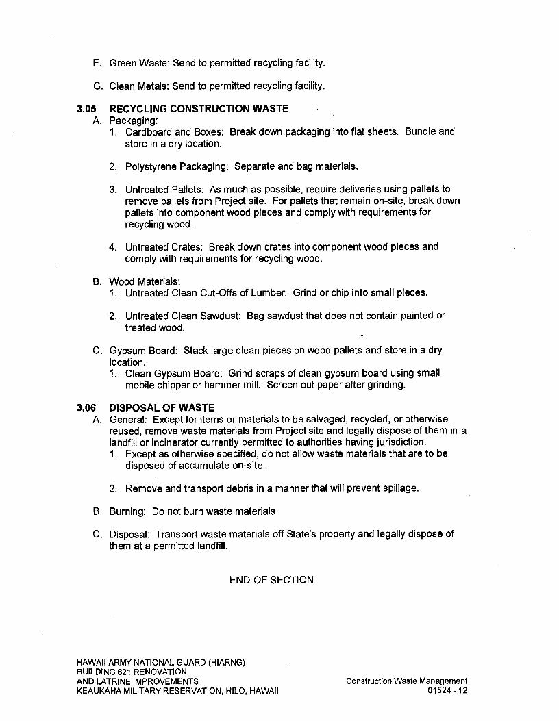
F. Green Waste: Send to permitted recycling facility.
G. Clean Metals: Send to permitted recycling facility.
3.05 RECYCLING CONSTRUCTION WASTE A. Packaging:
1. Cardboard and Boxes: Break down packaging into flat sheets. Bundle and store in a dry location.
2. Polystyrene Packaging: Separate and bag materials.
3. Untreated Pallets: As much as possible, require deliveries using pallets to remove pallets from Project site. For pallets that remain on-site, break down pallets into component wood pieces and comply with requirements for recycling wood.
4. Untreated Crates: Break down crates into component wood pieces and comply with requirements for recycling wood.
B. Wood Materials: 1. Untreated Clean Cut-Offs of Lumber: Grind or chip into small pieces.
2. Untreated Clean Sawdust: Bag sawdust that does not contain painted or treated wood.
C. Gypsum Board: Stack large clean pieces on wood pallets and store in a dry location. 1. Clean Gypsum Board: Grind scraps of clean gypsum board using small
mobile chipper or hammer mill. Screen out paper after grinding.
3.06 DISPOSAL OF WASTE A. General: Except for items or materials to be salvaged, recycled, or otherwise
reused, remove waste materials from Project site and legally dispose of them in a landfill or incinerator currently permitted to authorities having jurisdiction. 1. Except as otherwise specified, do not allow waste materials that are to be
disposed of accumulate on-site.
2. Remove and transport debris in a manner that will prevent spillage.
B. Burning: Do not burn waste materials.
C. Disposal: Transport waste materials off State's property and legally dispose of them at a permitted landfill.
END OF SECTION
HAWAII ARMY NATIONAL GUARD (HIARNG) BUILDING 621 RENOVATION AND LATRINE IMPROVEMENTS
Construction Waste Management
KEAUKAHA MILITARY RESERVATION, HILO, HAWAII
01524-12
APPENDIX A
WASTE MANAGEMENT PLAN
Project Title: <Insert Project Title>
Waste Management Coordinator: <Insert Name, Title, and contact information>
Recycling Requirement - To recycle/salvage <Insert Percentage> of waste generated on the site.
HAWAII ARMY NATIONAL GUARD (HlARNG) BUILDING 621 RENOVATION ANDLATRI NE- IMPROVEMENTS
Appendix A
KEAUKAHA MILITARY RESERVATION, HILO, HAWAII
Page 1 of 4

Com
men
ts/A
ssu
mpt
ions
Poi
nt of G
ener
atio
n
z 0
0 LJ
z Ui 0
w I
LLJ
-
U) C 0
U) w
U) Ui
HAWAII ARMY NATIONAL GUARD (HIARNG) BUILDING 621 RENOVATION AND LATRINE IMPROVEMENTS
Appendix A
KEAUKAHA MILITARY RESERVATION, HILO, HAWAII
Page 2 of 4
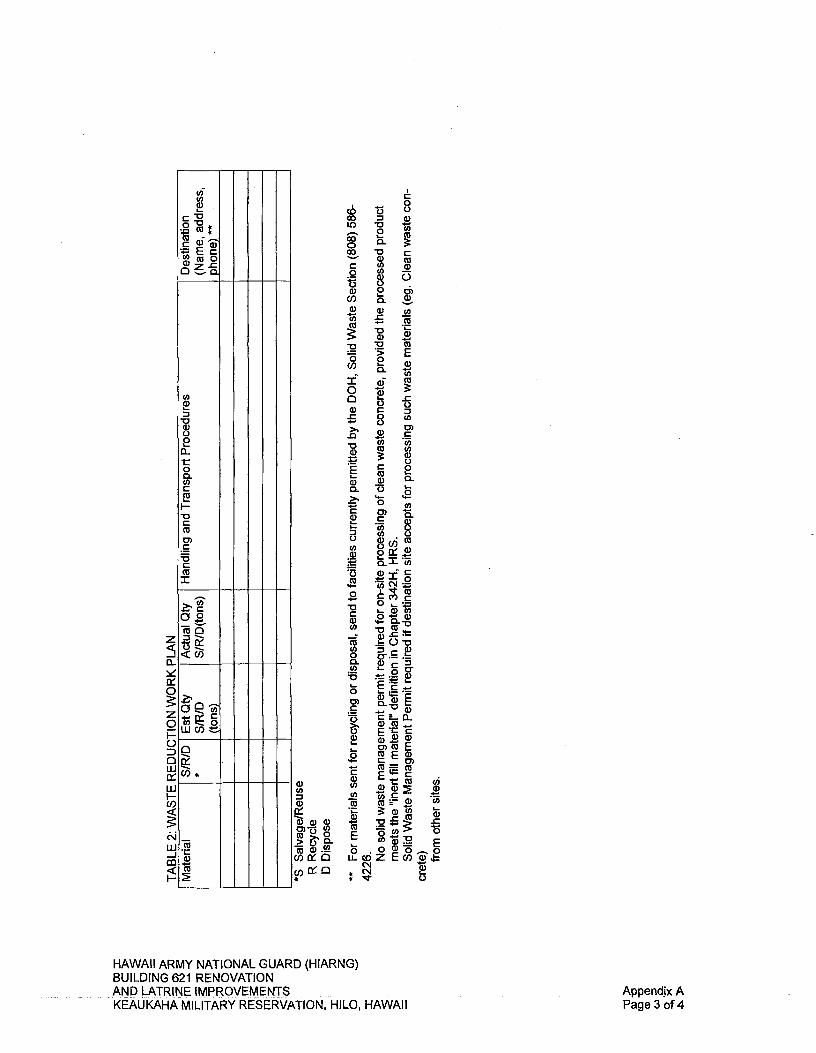
0 c6li 0
U) L0V CO
0 CL CO 0
U) CO C CO o t 3 a) 0 0) Co 0. a) w U)
00 CO CL
Iac o; U) C
— 0)
Cl) o CO U)
C C 0 cu CL
0
C a) C
C.) U)jCO
Cl)
9-
.2 ~:X
U) -
• .!0V (I) a) 0 c._._ 0. Cl) 0
0
= U) CO.,
c' ECC 0)Cu E
' 9- C 0) — CU C U) Cl) a)a) Cl) coC • (0:
a)C/) . v.CCu
o w E
0 LJC0Z Eco Cs1 C's.I
U a) Cl)
z
0
0
z 0 I- 0
0 U]
U]
Lu
Des
tina
tion
(Nam
e, a
ddre
ss,
ph
one)
**
Han
dli
ng a
nd
Tra
nsp
ort
Pro
ced
ure
s A
ctua
l Qty
S
IR/D
(to
ns)
E
st Q
ty
S/R
ID
L(t
on
s)
0
CO
(0
a) Cu
HAWAII ARMY NATIONAL GUARD (HIARNG) BUILDING 621 RENOVATION AND LATRINE IMPROVEMENTS
Appendix A
KEAUKAHA MILITARY RESERVATION, HILO, HAWAII
Page 3 of 4

HAWAII ARMY NATIONAL GUARD (HIARNG) BUILDING 621 RENOVATION AND LATRINE IMPROVEMENTS
Appendix A
KEAUKAHA MILITARY RESERVATION, HILO, HAWAII
Page 4 of 4

SECTION 01700 - EXECUTION REQUIREMENTS
PART I -GENERAL
1.01 SUMMARY A. This Section includes general procedural requirements governing execution of
the Work including the following: 1. Construction layout. Field engineering and surveying.
2. General installation of products.
3. Progress cleaning.
4. Starting and adjusting.
5. Protection of installed construction.
6. Correction of the Work.
B. Related Sections 1. SECTION 01770- CLOSEOUT PROCEDURES.
1.02 SUBMITTALS A. Landfill Receipts: Submit copy of receipts issued by a landfill facility, licensed to
accept hazardous materials, for hazardous waste disposal.
1.03 NOTIFICATION A. Contact the Project Manager and the Project Contact Person at least 3 working
days prior to starting any onsite work.
1.04 PROJECT AND SITE CONDITIONS A. Project Contract Limits (Contract Zone Limits) indicate only in general the limits
of the work involved. Perform necessary and incidental work, which may fall outside of these demarcation lines. Confine construction activities within the Project Contract Limits and do not spread equipment and materials indiscriminately about the area.
B. Disruption of Utility Services: Prearrange work related to the temporary disconnection of electrical and other utility systems with the Project Contact Person listed in the SPECIAL CONDITIONS and the Project Manager. Unless a longer notification period is required elsewhere in the Contract Documents, notify the Project Manager at least 15 days in advance of any interruption of existing utility service. Time and duration of interruptions are subject to the Project Manager's approval. Keep the utility interruptions and duration to a minimum so as not to cause inconvenience or hardship to the facility. If temporary electrical or other utility systems hook-up is required, provide the necessary services. Pay for temporary services as part of the contract, unless specifically noted otherwise.
HAWAII ARMY NATIONAL GUARD (HIARNG) BUILDING 621 RENOVATION AND LATRINE IMPROVEMENTS
Execution Requirements
KEAUKAHA MILITARY RESERVATION, HILO, HAWAII
01700-1

C. Contractor, Subcontractor(s) and their employees will not be allowed to park in zones assigned to Users or facility personnel. Subject to availability, the Project Manager may designate areas outside of the Contract Zone Limits to be used by the Contractor. Restore any lawn area damaged by construction activities.
1.05 QUALITY ASSURANCE A. Land Surveyor Qualifications: A professional land surveyor with a license to
practice in Hawaii.
B. Professional Engineer Qualifications: A professional engineer with a license to practice in Hawaii.
PART 2- PRODUCTS (Not Used)
PART 3- EXECUTION
3.01 EXAMINING THE SITE A. Contractor and Subcontractors are expected to visit the site and make due
allowances for difficulties and contingencies to be encountered. Compare contract documents with work in place. Become familiar, with existing conditions, the conditions to be encountered in performing the Work, and the requirements of the drawings and specifications.
B. Verify construction lines, grades, dimensions and elevations indicated on the drawings before any clearing, excavation or construction begins. Bring any discrepancy to the attention of the Project Manager, and make any change in accordance with the Project Manager instruction.
C. Obtain all field measurements required for the accurate fabrication and installation of the Work included in this Contract. Verify governing dimensions and examine adjoining work on which the Contractor or Subcontractor's work is in any way dependent. Submit differences discovered during the verification work to the Project Manager for interpretations before proceeding with the associated work. Exact measurements are the Contractor's responsibility.
D. Furnish or obtain templates, patterns, and setting instructions as required for the installation of all Work. Verify dimensions in the field.
E. Contractor shall accept the site in the condition that exists at the time access is granted to begin the Work. Verify existing conditions and dimensions shown and other dimensions not indicated but necessary to accomplish the Work.
F. Locate all general reference points and take action to prevent their destruction. Lay out work and be responsible for lines, elevations and measurements and the work executed. Exercise precautions to verify figures and conditions shown on drawings before layout of work.
HAWAII ARMY NATIONAL GUARD (HIARNG) BUILDING 621 RENOVATION AND LATRINE IMPROVEMENTS
Execution Requirements
KEAUKAHA MILITARY RESERVATION, HILO, HAWAII
01700-2
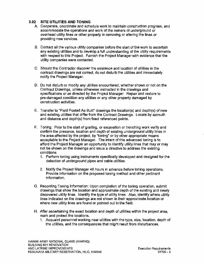
3.02 SITE UTILITIES AND TONING A. Cooperate, coordinate and schedule work to maintain construction progress, and
accommodate the operations and work of the owners of underground or overhead utility lines or other property in removing or altering the lines or providing new services.
B. Contact all the various utility companies before the start of the work to ascertain any existing utilities and to develop a full understanding of the utility requirements with respect to this Project. Furnish the Project Manager with evidence that the utility companies were contacted.
C. Should the Contractor discover the existence and location of utilities in the contract drawings are not correct, do not disturb the utilities and immediately notify the Project Manager.
D. Do not disturb or modify any utilities encountered, whether shown or not on the Contract Drawings, unless otherwise instructed in the drawings and specifications or as directed by the Project Manager. Repair and restore to pre-damaged condition any utilities or any other property damaged by construction activities.
E. Transfer to "Field Posted As-Built" drawings the location(s) and depth(s) of new and existing utilities that differ from the Contract Drawings. Locate by azimuth and distance and depth(s) from fixed referenced points.
F. Toning: Prior to the start of grading, or excavation or trenching work verify and confirm the presence, location and depth of existing underground utility lines in the area affected by the project, by "toning" or by other appropriate means acceptable to the Project Manager. The intent of this advanced toning is to afford the Project Manager an opportunity to identify utility lines that may or may not be shown on the drawings and issue a directive to address the existing conditions. 1. Perform toning using instruments specifically developed and designed for the
detection of underground pipes and cable utilities.
2. Notify the Project Manager 48 hours in advance before toning operations. Provide information on the proposed toning method and other pertinent information.
G. Recording Toning Information: Upon completion of the toning operation, submit drawings that show the location and approximate depth of the existing and newly discovered utility lines. Identify the type of utility lines. Also, identify where utility lines indicated on the drawings are not shown in their approximate location or where new utility lines are found or pointed out in the field.
H. After ascertaining the exact location and depth of utilities within the project area, mark and protect the locations. 1. Acquaint personnel working near utilities with the type, size, location, depth of
the utilities, and the consequences that might result from disturbances.
HAWAII ARMY NATIONAL GUARD (HIARNG) BUILDING 621 RENOVATION AND LATRINE IMPROVEMENTS
Execution Requirements
KEAUKAHA MILITARY RESERVATION, HILO, HAWAII
01700-3

2. Do not start trenching or start similar operations until reasonable and appropriate precautions to protect the utilities are taken.
I. For newly identified utility lines, if directed by the Project Manager, manually excavate within 2-feet of the utility line to avoid damage. Under this directive, manual excavation is considered additional work.
3.03 FIELD MEASUREMENTS A. Take field measurements to fit and install the Work properly. Where portions of
the Work are indicated to fit to other construction, verify dimensions of other construction by field measurements before fabrication. Coordinate fabrication schedule with construction progress.
B. Space Requirements: Verify space requirements and dimensions of items shown diagrammatically on Drawings.
C. Review of Contract Documents and Field Conditions: Submit a Request For Information (RFI) immediately upon discovery of the need for clarification of the Contract Documents. Include a detailed description of problem encountered, together with recommendations for changing the Contract Documents.
3.04 CONSTRUCTION LAYOUT A. Verification: Before proceeding to lay out the Work, verify layout information
shown on Drawings, in relation to existing conditions. If discrepancies are discovered, notify the Project Manager promptly.
B. General: Engage a licensed land surveyor to lay out the Work using accepted surveying practices. 1. Establish benchmarks, control points, lines and levels at each story or level of
construction and elsewhere as needed to locate each element of Project.
2. Establish dimensions within tolerances indicated. Do not scale Drawings to obtain required dimensions.
3. Inform installers of lines and levels to which they must comply.
4. Check the location, level and plumb, of every major element as the Work progresses.
5. Notify the Project Manager when deviations from required lines and levels exceed allowable tolerances.
6. Close site surveys with an error of closure equal to or less than the standard established by authorities having jurisdiction.
C. Site Improvements: Locate and lay out site improvements, including pavements, grading, fill and topsoil placement, utility slopes, and invert elevations.
HAWAII ARMY NATIONAL GUARD (HIARNG) BUILDING 621 RENOVATION AND LATRINE IMPROVEMENTS
Execution Requirements
KEAUKAHA MILITARY RESERVATION, HILO, HAWAII
01700-4
D. Building Lines and Levels: Locate and lay out control lines and levels for structures, building foundations, column grids, and floor levels, including those required for mechanical and electrical work. Transfer survey markings and elevations for use with control lines and levels. Level the foundations and piers from 2 or more locations.
E. Record Log: Maintain a log of layout control work. Record deviations from required lines and levels. Include beginning and ending dates and times of surveys, weather conditions, name and duty of each survey party member, and types of instruments and tapes used. Make the log available for reference by the Project Manager.
3.05 FIELD ENGINEERING A. Reference Points: Locate existing permanent or temporary benchmarks, control
points and similar reference points before beginning the Work. Preserve and protect permanent benchmarks and control points during construction operations. 1. Do not change or relocate existing benchmarks or control points without the
Project Manager's approval. Report lost or destroyed permanent benchmarks or control points promptly. Report the need to relocate permanent benchmarks or control points to the Project Manager before proceeding.
2. Replace lost or destroyed permanent benchmarks and control points promptly. Base all replacements on the original survey control points.
B. Benchmarks: Establish and maintain a minimum of 2 permanent or temporary benchmarks on Project site, referenced to data established by survey control points. Comply with authorities having jurisdiction for type and size of benchmark. 1. Record benchmark locations, with horizontal and vertical data, on Project
Record Documents.
2. Where the actual location or elevation of layout points cannot be marked, provide temporary reference points sufficient to locate the Work.
3. Remove temporary reference points when no longer needed. Restore marked construction to its original condition.
306 INSTALLATION A. Install materials, items, fixtures required by the various Divisions and Sections of
the Specifications in accordance with Contract Documents, by workers specially trained and skilled in performance of the particular type of work, to meet guarantee and regulatory agency requirements. Should the drawings or specifications be void of installation requirements, install the materials, items, and fixtures in accordance with the manufacturer's current specifications, recommendations, instructions and directions.
HAWAII ARMY NATIONAL GUARD (HIARNG) BUILDING 621 RENOVATION AND LATRINE IMPROVEMENTS
Execution Requirements
KEAUKAHA MILITARY RESERVATION, HILO, HAWAII
01700-5
3.07 CUTTING AND PATCHING A. Oversee cutting and patching of concrete, masonry, structural members and
other materials where indicated on drawings and as required by job conditions. Unless noted elsewhere in the contract documents, do not cut or patch existing or new structural members without previously notifying the Project Manager.
B. Provide patch materials and workmanship of equal quality to that indicated on the drawings or specified for new work.
3.08 CLEANING A. General: Clean the Project site and work areas daily, including common areas.
Coordinate progress cleaning for joint-use areas where more than one installer has worked. Enforce requirements strictly. Dispose of materials lawfully. 1. Comply with requirements in NFPA 241 for removal of combustible waste
materials and debris.
2. Do not hold waste more than 7 days unless approved otherwise by the Project Manager.
3. Containerize hazardous and unsanitary waste materials separately from other waste. Mark containers appropriately and dispose of legally, according to regulations.
B. Site: Maintain Project site free of waste materials and debris.
C. Work Areas: Clean areas where work is in progress to the level of cleanliness necessary for proper execution of the Work. 1. Remove liquid spills promptly.
2. Where dust would impair proper execution of the Work, broom-clean or vacuum the entire work area, as appropriate.
D. Installed Work: Keep installed work clean. Clean installed surfaces according to written instructions of manufacturer or fabricator of product installed, using only cleaning materials specifically recommended. If specific cleaning materials are not recommended, use only cleaning materials that are not hazardous to health or property and that will not damage exposed surfaces.
E. Concealed Spaces: Remove debris from concealed spaces before enclosing the space.
F. Exposed Surfaces: Clean exposed surfaces and protect as necessary to ensure freedom from damage and deterioration at time of Substantial Completion.
G. Cutting and Patching: Clean areas and spaces where cutting and patching are performed. Completely remove paint, mortar, oils, putty, and similar materials. Thoroughly clean piping, conduit, and similar features before applying paint or other finishing materials. Restore damaged pipe covering to its original condition.
HAWAII ARMY NATIONAL GUARD (HIARNG) BUILDING 621 RENOVATION AND LATRINE IMPROVEMENTS
Execution Requirements
KEAUKAHA MILITARY RESERVATION, HILO, HAWAII
01700-6

H. Waste Disposal: Burying or burning waste materials on-site will not be permitted. Washing waste materials down sewers or into waterways will not be permitted.
I. During handling and installation, clean and protect construction in progress and adjoining materials already in place. Apply protective covering where required to ensure protection from damage or deterioration at Substantial Completion.
J. Clean and provide maintenance on completed construction as frequently as necessary through the remainder of the construction period. Adjust and lubricate operable components to ensure operability without damaging effects.
K. Limiting Exposures: Supervise construction operations to assure that no part of the construction, completed or in progress, is subject to harmful, dangerous damaging, or otherwise deleterious exposure dunng the construction period.
3.09 STARTING AND ADJUSTING A. Start equipment and operating components to confirm proper operation.
Remove malfunctioning units, replace with new units, and retest.
B. Adjust operating components for proper operation without binding. Adjust equipment for proper operation.
C. Test each piece of equipment to verify proper operation. Test and adjust controls and safeties. Replace damaged and malfunctioning controls and equipment.
3.10 PROTECTION OF INSTALLED CONSTRUCTION A. Provide final protection and maintain conditions that ensure installed Work is
without damage or deterioration at time of Substantial Completion.
B. Comply with manufacturer's written instructions to provide proper temperature and relative humidity conditions.
3.11 CORRECTION OF THE WORK A. Repair or replace defective construction. Restore damaged substrates and
finishes. Repairing includes replacing defective parts, refinishing damaged surfaces, touching up with matching materials, and properly adjusting operating equipment.
B. Restore permanent facilities used during construction to their specified condition.
C. Remove and replace damaged surfaces that are exposed to view if surfaces cannot be repaired without visible evidence of repair.
D. Repair defective components that do not operate properly. Remove and replace operating components that cannot be repaired.
E. Remove and replace chipped, scratched, and broken glass or reflective surfaces.
END OF SECTION
HAWAII ARMY NATIONAL GUARD (HIARNG) BUILDING 621 RENOVATION AND LATRINE IMPROVEMENTS
Execution Requirements
KEAUKAHA MILITARY RESERVATION, HILO, HAWAII
01700-7

SECTION 01715 - EXISTING CONDITIONS ASBESTOS! LEAD I HAZARDOUS MATERIAL SURVEY
PART I -GENERAL
1.01 SUMMARY A. This section includes the results of the State's survey for hazardous materials and
is provided for the Contractor's information.
B. Related Sections include the following: 1. SECTION 13282 - LEAD AND ARSENIC IN CONSTRUCTION for
requirements of all work which disturbs LCP, LBP, and Arsenic. Also, refer to the drawings.
2. SECTION 13286 - HANDLING OF LIGHTING BALLASTS AND LAMPS CONTAINING PCBS AND MERCURY for requirements of all work which disturbs lighting systems. Also refer to the drawings.
1.02 ASBESTOS A. The structure or structures to be renovated or modified under this contract were
surveyed for the presence of asbestos containing building materials (ACBM), using AHERA requirements. A copy of the initial survey report, as well as any subsequent supplemental survey report(s) if performed, are included in this Section. 1. The report(s) are included, even when no ACBM was found, for the
Contractor's information. Contractor may perform further surveys at its own expense, if ACBM not shown in the report(s) is suspected in the areas of the building(s) in which work will be performed. If ACBM is found, notify the Project Manager immediately. The State will reimburse the Contractor for the testing cost if ACBM is found.
2. If there is ACBM outside of the areas in which work will be performed, this ACBM shall not be disturbed in any way.
B. If applicable, notify employees, Subcontractors and all other persons engaged on the project of the presence of asbestos in the existing buildings in accordance with the requirements of Chapter 110, Article 12-110-2 (f) (1) (B) of the Occupational Safety and Health Standards, State of Hawaii.
C. In the event that work is required in any building or buildings on the site other than the one(s) designated within this project scope, request copies of the asbestos survey report(s) for such building(s) from the Project Manager. Based on the information contained in the additional survey(s), notify affected personnel per paragraph 1.02 B.
1.03 LEAD AND ARSENIC A. Inform employees, Subcontractors and all other persons engaged in the project
that lead containing paints (LCP), lead based paints (LBP), and arsenic containing materials are present in the existing building(s) and at the job site. Follow the
HAWAII ARMY NATIONAL GUARD (HIARNG) BUILDING 621 RENOVATION AND LATRINE IMPROVEMENTS
Existing Conditions - Asbestos / Lead /
KEAUKAHA MILITARY RESERVATION, HILO, HAWAII
Hazardous Material Survey 01715 - 1

requirements of Title 12 (Department of Labor and Industrial Relations), Subtitle 8 (Division of Occupational Safety and Health), Chapter 148 (Lead Exposure in Construction), and Chapter 202 (Inorganic Arsenic) Hawaii Administrative Rules.
B. Review the attached lead and arsenic testing data which identify locations LCP, LBP and arsenic was found. Lead and arsenic testing was for design purposes only, and the results do not satisfy any of the requirements of Chapter 12-148.
1.04 LIGHTING A. Inform employees, Subcontractors and all other persons engaged in the project
that lighting systems may contain PCBs and mercury which are present in the existing building(s) and at the job site.
PART 2- PRODUCTS (Not Used)
PART 3- EXECUTION
3.01 SURVEY A. Masa Fujioka and Associates (MFA) has conducted two (2) limited hazardous
materials surveys to identify potentially hazardous materials that are expected to be disturbed during renovation activities. One survey was conducted on the HIARNG portion of Building 621 and the other on the YCA portion of Building 621. The results of MFA's surveys are contained in the reports: 1. REPORT OF FINDINGS, HAZARDOUS MATERIALS TESTING SERVICES,
Project Numbers: Federal: 15130007; State: CA-1212-C, Keaukaha Military Reservation, Building 621, Hawaii Army National Guard (HIARNG) (Phase 1), 1046 Leilani Street, Hilo, Hawaii Island, Hawaii, 34 pages, dated January 23, 2013.
2. REPORT OF FINDINGS, HAZARDOUS MATERIALS TESTING SERVICES, Project Numbers: Federal: 15130007; State: CA-1212-C, Keaukaha Military Reservation, Building 621, Hawaii Youth Challenge Academy (YCA) (Phase 2-3), 1046 Leilani Street, Hilo, Hawaii Island, Hawaii, 34 pages, dated January 25, 2013.
END OF SECTION
HAWAII ARMY NATIONAL GUARD (HIARNG) BUILDING 621 RENOVATION AND LATRINE IMPROVEMENTS
Existing Conditions - Asbestos I Lead /
KEAUKAHA MILITARY RESERVATION, HILO, HAWAII
Hazardous Material Survey 01715 - 2

REPORT OF FINDINGS HAZARDOUS MATERIALS TESTING SERVICES
Project Numbers: Federal: 15130007; State: CA-1212-C Keaukaha Military Reservation, Building 621
Hawaii Army National Guard (HIARNG) (Phase 1) 1046 Leilani Street, Hilo, Hawaii Island, Hawaii
January 23, 2013
MASA FUJIOKA & ASSOCIATES Job Number 12062-051
HAWAII ARMY NATIONAL GUARD (HIARNG) BUILDING 621 RENOVATION AND. LATRINE- IMPROVEMENTS, Report of Findings,. Hazardous Materials Testing KEAUKAHA MILITARY RESERVATION, HILO, HAWAII Services (Phase 1) Page 1 of 34

MASA FUJIOKA & ASSOCIATES Environmental . Geotechnical. Hydrogeological Consultants
98-021 Kamehameha Highway, Suite 337 ' Aiea, Hawaii 96701-4914 Telephone: (808) 484-5366 • Facsimile: (808) 484-0007
January 23, 2013
MFA Job No. 12062-051
Architects Hawaii, Ltd. Pacific Guardian Center, Makai Tower 733 Bishop Street, Suite 3100 Honolulu, Hawaii 96813
Attention: Mr. Lloyd T. Arakaki
Subject: Report of Findings Hazardous Materials Testing Services Project Numbers: Federal: 15130007; State: CA-1212-C Keaukaha Military Reservation, Building 621 Hawaii Army National Guard (HIARNG) (Phase 1) 1046 Leilani Street, Hhlo, Hawaii Island, Hawaii
Dear Mr. Arakaki:
Masa Fujioka & Associates (MFA) has performed sampling for hazardous materials at the above-referenced site. MFA collected bulk building material samples and paint chip samples in areas we understood will be affected by the planned project. The results are contained in this report. It has been a pleasure performing this service for you. Please contact the undersigned at 484-5366 or [email protected] if you have any questions regarding this report.
Respectfully submitted,
MASA FUJIOKA & ASSOCIATES A Professional Partnershi?
David J. Maier Hazardous Materials Project Designer
HAWAII ARMY NATIONAL GUARD (HIARNG) BUILDING 621 RENOVATION AND LATRINE IMPROVEMENTS - Report of Findings, HazardousMaterialsTesting KEAUKAHA MILITARY RESERVATION, HILO, HAWAII Services (Phase 1) Page 2 of 34
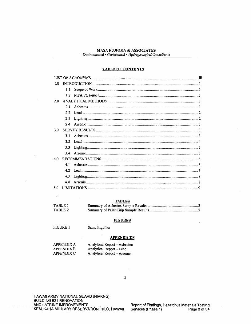
MASA FUJIOKA & ASSOCIATES Environmental • Geotechnical • Hydrogeological Consultants
TABLE OF CONTENTS
LIST OF ACRONYMS iii
1.0 INTRODUCTION 1 1.1 Scope of Work 1
1.2 MFA Personnel 1
2.0 ANALYTICAL METHODS 1
2.1 Asbestos 1
2.2 Lead 2
2.3 Lighting 2
2.4 Arsenic 3 3.0 SURVEY RESULTS 3
3.1 Asbestos 3 3.2 Lead 4
3.3 Lighting 5
3.4 Arsenic 5
4.0 RECOMMENDATIONS 6 4.1 Asbestos 6 4.2 Lead 7 4.3 Lighting 8 4.4 Arsenic 8
5.0 LIMITATIONS 9
TABLES TABLE 1 Summary of Asbestos Sample Results 3 TABLE 2 Summary of Paint Chip Sample Results 5
FIGURES
FIGURE 1 Sampling Plan
APPENDICES
APPENDIX A
Analytical Report - Asbestos APPENDIX B
Analytical Report - Lead APPENDIX C
Analytical Report - Arsenic
11
HAWAII ARMY NATIONAL GUARD (HIARNG) BUILDING 621 RENOVATION AND LATRINE IMPROVEMENTS
Report of Findings, Hazardous Materials Testing
KEAUKAHA MILITARY RESERVATION, HILO, HAWAII Services (Phase 1) Page 3 of 34

MASA FUJIOKA & ASSOCIATES Environmental • Geotechnical Hydrogeological Consultants
LIST OF ACRONYMS
AAS Atomic Absorption Spectroscopy ACM Asbestos-Containing Material AHERA Asbestos Hazard Emergency Response Act AIHA American Industrial Hygiene Association CDC Centers for Disease Control and Prevention CFR Code of Federal Regulations DOH Hawaii State Department of Health EAL Environmental Action Level EHE Environmental Hazard Evaluation ELLAP Environmental Lead Laboratory Accreditation Program EPA U.S. Environmental Protection Agency HAR Hawaii Administrative Rules HEER Hazard Evaluation and Emergency Response HIOSH Hawaii Occupational Safety and Health HUD U.S. Department of Housing and Urban Development LBP Lead-Based Paint LCP Lead-Containing Paint WA Masa Fujioka and Associates ND Not detected NESHAP National Emission Standards for Hazardous Air Pollutants NIOSH National Institute for Occupational Safety and Health NVL NVL Laboratories, Inc. NVLAP National Voluntary Laboratory Accreditation Program OSHA Occupational Safety and Health Administration PCBs Polychlorinated Biphenyls PLM Polarized Light Microscopy PPE Personal Protective Equipment RACM Regulated Asbestos Containing Material TCLP Toxicity Characteristic Leaching Procedure TSCA Toxic Substance Control Act TSI Thermal System Insulation
111
HAWAII ARMY NATIONAL GUARD (HIARNG) BUILDING 621 RENOVATION AND LATRINE IMPROVEMENTS
Report of Findings, Hazardous Materials Testing
KEAUKAHA MILITARY RESERVATION, HILO, HAWAII Services (Phase 1) Page 4 of 34

MASA FUJ1OKA & ASSOCIATES Environmental • Geotechnical e Hydrogeological Consultants
REPORT OF FINDINGS HAZARDOUS MATERIALS TESTING SERVICES
Project Numbers: Federal: 15130007; State: CA-1212-C Keaukaha Military Reservation, Building 621
Hawaii Army National Guard (HIARNG) (Phase 1) 1046 Leilani Street, Hilo, Hawaii Island, Hawaii
1.0 INTRODUCTION
1.1 Scope of Work
Masa Fujioka and Associates (MFA) was retained by Architects Hawaii, Ltd. to perform sampling and testing services at the above-referenced project site. Our scope of work included conducting a visual survey and sampling of materials at the Hawaii Army National Guard (HIARNG) portion of Building 621 where components and materials are expected to be disturbed. MFA sampled materials for the presence of asbestos, arsenic, and lead (in paint). Building lighting systems were visually checked to evaluate the potential presence of polychlorinated biphenyls (PCBs) and mercury.
It should be noted that Rooms 12-16, 22, 23, 27-29, 32-34, and 36 were not accessible at the time of our initial visit. During a subsequent visit on January 8, 2013, MFA observed Rooms 27 and 28. No new representative materials were observed in these rooms.
1.2 MFA Personnel
Mr. David Maier visited the site and collected bulk building material samples on October 12, 2012. Mr. Maier is an Asbestos Hazard Emergency Response Act (AHERA)-accredited Asbestos Inspector and Asbestos Project Designer certified in the State of Hawaii in accordance with Hawaii Administrative Rules (HAR) Title 11, Chapter 504, Asbestos Abatement Certification Program (DOH card: HIASB-2548). Mr. Maier is also certified by the State of Hawaii as a Lead Inspector and Lead Risk Assessor in accordance with Chapter 11-41 HAR and the Toxic Substance Control Act (TSCA) Section 402 (a)(2) (DOH card: PB-0240).
2.0 ANALYTICAL METHODS
2.1 Asbestos
Twenty-seven (27) bulk samples from nine (9) homogeneous suspect materials were collected in areas that we were told would be affected by the proposed project. Samples were obtained with the intent to be representative of materials a contractor may encounter during this work. Samples were submitted to NVL Laboratories, Inc. (NVL) for analysis. The following is a summary of the survey and sampling process:
Hazardous Materials Testing Services
MFA Project No. 12062-051 KMR B621 HIARNG, Hilo, HI January 23, 2013
HAWAII ARMY NATIONAL GUARD (HIARNG) BUILDING 621 RENOVATION AND. LATRINE IMPROVEMENTS
Report of Findings, Hazardous Materials Testing
KEAUKAHA MILITARY RESERVATION, HILO, HAWAII Services (Phase 1) Page 5 of 34

MASA FUJ1OKA & ASSOCIATES Environmental • Geotechnical . Hydrogeological Consultants
• Review existing drawings • Conduct walk-through to corroborate drawings with existing conditions • Assess materials to be sampled • Delineate homogeneous sampling areas and develop a sampling plan • Record material/sample information onto field log • Obtain samples
NVL is a National Voluntary Laboratory Accreditation Program (NVLAP)-accredited laboratory. Their accreditation number is 102063-0 for "Bulk Asbestos Fiber Analysis." Their office is located at 4708 Aurora Avenue North, Seattle, Washington, 98103.
The samples were analyzed using polarized light microscopy (PLM) with dispersion staining according to U. S. Environmental Protection Agency (EPA) Method 6001M4-82-020. Appropriate chain-of-custody procedures were followed in submitting the samples to the laboratory.
2.2 Lead
Eight (8) paint chip samples were collected in areas that we were told would be affected by the proposed project. Samples were obtained with the intent to be representative of materials a contractor may encounter during this work. Testing combinations were selected by observing building component and substrate. Samples were submitted to NVL for total lead analysis. The following is a summary of the survey and sampling process:
• Review existing drawings • Conduct walk-through to corroborate drawings with existing conditions • Assess surfaces to be sampled • Delineate functional spaces, components, substrates and surface colors to develop
a sampling plan • Record material/sample information onto field log • Obtain samples
The samples were analyzed using Flame Atomic Absorption Spectrophotometry, EPA Method SW 846-3051/7000B. NVL currently participates in the Environmental Lead Laboratory Accreditation Program (ELLAP). The ELLAP is administered by the American Industrial Hygiene Association (AIHA) in cooperation with the Centers for Disease Control and Prevention (CDC), National Institute for Occupational Safety and Health (NIOSH), and EPA. Their AIHA-ELLAP accreditation number is 101861. Appropriate chain-of-custody procedures were followed in submitting the samples to the laboratory.
2.3 Lighting
MFA observed lighting systems throughout the spaces. Representative lighting ballasts were checked for the presence of "No PCB" labels to assess their PCB status.
Hazardous Materials Testing Services
2 MFA Project No. 12062-051 KMR B621 HIARNG, Hilo, HI January 23, 2013
HAWAII ARMY NATIONAL GUARD (HIARNG) BUILDING 621 RENOVATION AND-LATRINE. IMPROVEMENTS
Report-of-Findings, Hazardous Materials Testing
KEAUKAHA MILITARY RESERVATION, HILO, HAWAII Services (Phase 1) Page 6 of 34
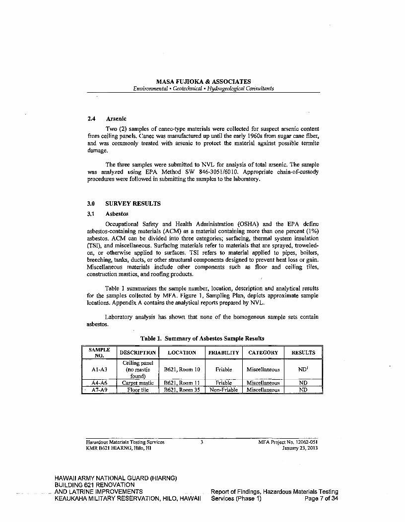
MASA FUJIOKA & ASSOCIATES Environmental • Geotechnical 'Hydrogeological Consultants
2.4 Arsenic
Two (2) samples of canec-type materials were collected for suspect arsenic content from ceiling panels. Canec was manufactured up until the early 1960s from sugar cane fiber, and was commonly treated with arsenic to protect the material against possible termite damage.
The three samples were submitted to NVL for analysis of total arsenic. The sample was analyzed using EPA Method SW 846-3051/6010. Appropriate chain-of-custody procedures were followed in submitting the samples to the laboratory.
3.0 SURVEY RESULTS
3.1 Asbestos
Occupational Safety and Health Administration (OSHA) and the EPA define asbestos-containing materials (ACM) as a material containing more than one percent (1%) asbestos. ACM can be divided into three categories; surfacing, thermal system insulation (TSI), and miscellaneous. Surfacing materials refer to materials that are sprayed, troweled-on, or otherwise applied to surfaces. TSI refers to material applied to pipes, boilers, breeching, tanks, ducts, or other structural components designed to prevent heat loss or gain. Miscellaneous materials include other components such as floor and ceiling tiles, construction mastics, and roofing products.
Table 1 summarizes the sample number, location, description and analytical results for the samples collected by WA. Figure 1, Sampling Plan, depicts approximate sample locations. Appendix A contains the analytical reports prepared by NVL.
Laboratory analysis has shown that none of the homogenous sample sets contain asbestos.
Table 1. Summary of Asbestos Sample Results
SAMPLE DESCRIPTION LOCATION FRIABILITY CATEGORY RESULTS
A1-A3 Ceiling panel
(no mastic found)
B621, Room 10 Friable Miscellaneous ND'
A4-A6 Carpet mastic 13621, Room ii Friable Miscellaneous ND A7-A9 Floor tile B621, Room 35 Non-Friable Miscellaneous ND
Hazardous Materials Testing Services
3 MFA Project No. 12062-051 KMR B621 HIARNG, Hilo, HI
January 23, 2013
HAWAII ARMY NATIONAL GUARD (HIARNG) BUILDING 621 RENOVATION ANDLATRINE IMPROVEMENTS Report of Findings, Hazardous Materials Testing KEAUKAHA MILITARY RESERVATION, HILO, HAWAII Services (Phase 1) Page 7 of 34

MASA FUJIOKA & ASSOCIATES Environmental. Geotechnical 'Hydrogeological Consultants
A10-Al2
Window caulking @ frame and
concrete wall
B621, Room 10 exterior
Non-Friable Miscellaneous ND
A13-A15
Window caulking @
glass pane and frame
B621, Room 10 exterior
Non-Friable Miscellaneous ND
A16-A18
Window caulking @
glass pane and metal frame
B621, Room 20 interior
Non-Friable Miscellaneous ND
A19-A21
Window caulking @
glass pane and metal frame
B621, Room 11 interior
Non-Friable Miscellaneous ND
A22-A24 Roofing
(shingle and felt)
B621, Walkway Non-Friable Miscellaneous ND
A25-A27 Ceiling panel (perforated
square) B621, Room 40 Friable Miscellaneous ND
Samples listed in bold indicate asbestos-containing material ND' =None Detected
3.2 Lead
According to the U.S. Department of Housing and Urban Development (HUD) painted surfaces containing 0.5 percent (%) or greater are considered "lead-based" and painted surfaces that contain measurable lead below 0.5% are known as "lead-containing." Materials containing any measureable lead require special handling and disposal considerations when disturbed or removed.
Table 2 summarizes the sample number, description, location, and analytical results (reported in percent) obtained from the laboratory. Figure 1, Sampling Plan, depicts approximate sample locations. Appendix B contains the analytical reports prepared by NVL.
Laboratory analysis has shown that- three (3) of the representative surfaces sampled contained lead greater or equal to 0.5% and are therefore considered lead-based. Three (3) of the representative surfaces sampled contained measurable lead above the laboratory's detection limit but below the 0.5% threshold and are therefore considered lead-containing.
Hazardous Materials Testing Services
4 MFA Project No. 12062-051 KMR B621 HIARNG, Hilo, HI January 23, 2013
HAWAII ARMY NATIONAL GUARD (HIARNG) BUILDING 621 RENOVATION AND LATRINE IMPROVEMENTS
Report of Findings, Hazardous Materials Testing
KEAUKAHA MILITARY RESERVATION, HILO, HAWAII Services (Phase 1) Page 8 of 34
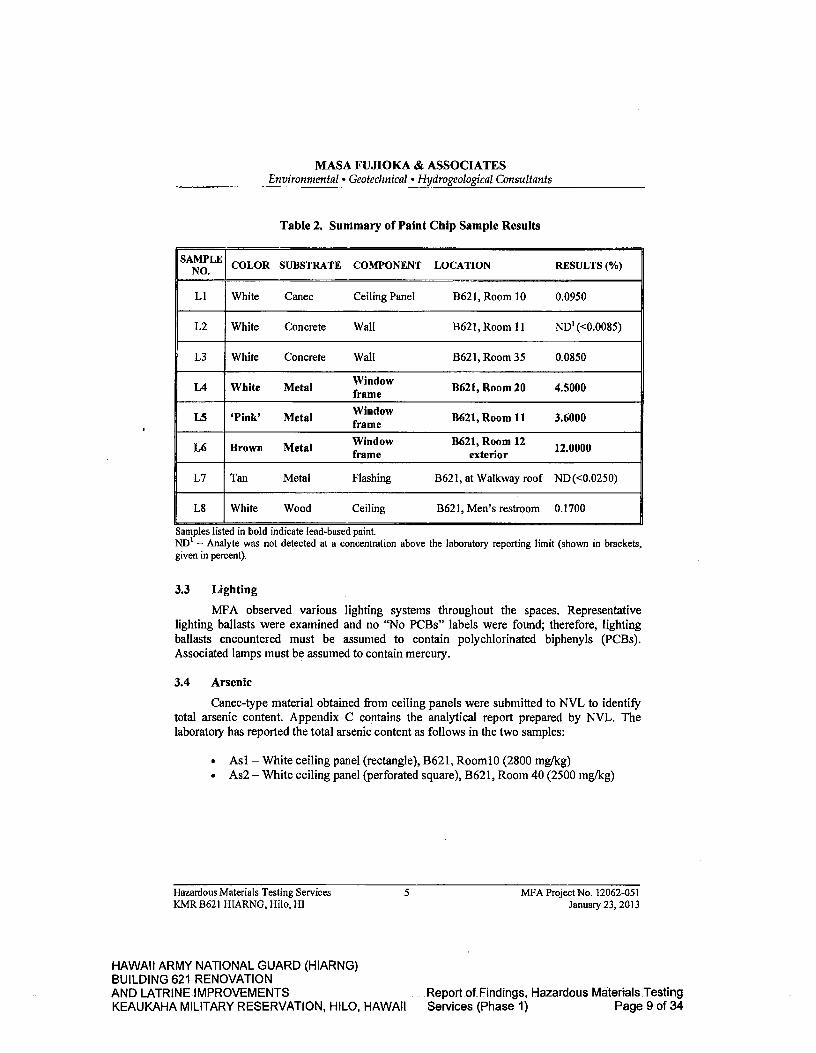
MASA FUJIOKA & ASSOCIATES Environmental. Geotechnical o Hydrogeological Consultants
Table 2. Summary of Paint Chip Sample Results
SAMPLE NO. COLOR SUBSTRATE COMPONENT LOCATION RESULTS (%)
Li White Canec Ceiling Panel B621, Room 10 0.0950
L2 White Concrete Wall 13621, Room 11 ND' (<0.0085)
L3 White Concrete Wall B621, Room 35 0.0850
L4 White Metal Window frame B621, Room 20 4.5000
L5 'Pink' Metal Window frame
B621, Room 11 3.6000
L6 Brown Metal Window frame
11621, Room 12 exterior
12.0000
L7 Tan Metal Flashing B621, at Walkway roof ND (<0.0250)
L8 White Wood Ceiling B621, Men's restroom 0.1700
Samples listed in bold indicate lead-based paint. ND' = Analyte was not detected at a concentration above the laboratory reporting limit (shown in brackets, given in percent).
3.3 Lighting
MFA observed various lighting systems throughout the spaces. Representative lighting ballasts were examined and no "No PCBs" labels were found; therefore, lighting ballasts encountered must be assumed to contain polychlorinated biphenyls (PCBs). Associated lamps must be assumed to contain mercury.
3.4 Arsenic
Canec-type material obtained from ceiling panels were submitted to NVL to identify total arsenic content. Appendix C contains the analytical report prepared by NVL. The laboratory has reported the total arsenic content as follows in the two samples:
• Asi - White ceiling panel (rectangle), B621, RoomlO (2800 mg/kg) • As2 - White ceiling panel (perforated square), B621, Room 40 (2500 mg/kg)
Hazardous Materials Testing Services 5 MFA Project No. 12062-051 KMR B621 HIARNG, Hilo, HI January 23, 2013
HAWAII ARMY NATIONAL GUARD (HIARNG) BUILDING 621 RENOVATION AND LATRINE IMPROVEMENTS
Report of Findings, Hazardous Materials Testing
KEAUKAHA MILITARY RESERVATION, HILO, HAWAII Services (Phase 1) Page 9 of 34

MASA FUJIOKA & ASSOCIATES Environmental • Geotechnical a Hydrogeological Consultants
4.0 RECOMMENDATIONS
4.1 Asbestos
Asbestos has not been identified in the homogenous sample sets obtained by MFA.
Should the scope of the planned project change or if hidden materials are encountered during the renovations which have not been previously characterized, suspect materials should be assumed to contain asbestos unless testing proves otherwise.
Where suspect or confirmed ACM is encountered, a qualified asbestos abatement contractor possessing a valid C-19 license should be retained to remove any ACM that will be affected before demolition or renovation operations begin that could disturb the material. Contractors that remove disturb, or dispose ACM must comply with all current federal and state regulations and contract specifications.
Specifically, when complying with the National Emission Standards for Hazardous Air Pollutants (NESHAP) requirements for asbestos, characterization of the material shall be followed inline with these standards. In general, these requirements include the removal and proper disposal of "Regulated Asbestos-Containing Material (RACM)." RACM is defined as friable asbestos material; Category I non-friable ACM that has become friable; Category I non-friable ACM that will be or has been subjected to sanding, grinding, cutting, or abrading; or Category II non-friable ACM that has a high probability of becoming or has become crumbled, pulverized, or reduced to powder by the forces expected to act on the material in the course of demolition or renovation operations.
When non-friable ACM is subjected to intense mechanical forces, such as those encountered during demolition or renovation, it can be crumbled, pulverized, or reduced to powder, and thereby release asbestos fibers. When non-friable materials are damaged or are likely to become damaged during such activities, they must be handled in accordance with the Asbestos NESHAP. Friable ACM must always be handled in accordance with the Asbestos NESHAP.
There are also notification requirements when certain quantities of RACM will be abated. These quantities include amounts greater than or equal to 160 square feet of RACM on facility components, 260 linear feet on pipes, or 35 cubic feet or more on facility components.
Hazardous Materials Testing Services
6 MFA Project No. 12062-051 KMR B621 HLARNG, Hilo, HI January 23, 2013
HAWAII ARMY NATIONAL GUARD (HIARNG) BUILDING 621 RENOVATION AND LATRINE IMPROVEMENTS
Report of Findings, Hazardous Materials Testing
KEAUKAHA MILITARY RESERVATION, HILO, HAWAII Services (Phase 1) Page 10 of 34

MASA FUJIOKA & ASSOCIATES Environmental • Geotechnical • Hydrogeological Consultants
4.2 Lead
Lead-based surfaces/paints have been identified in MFA's survey in the following samples:
• Sample L4, White metal window frame, 13621, Room 20 (4.5000%) • Sample L5, 'Pink' metal window frame, B621, Room 11(3.6000%) • Sample L6, Brown metal window frame, B621, Room 12 exterior (12.0000%)
Lead-containing surfaces/paints have been identified in MFA's survey in the following samples:
• Sample Li, White canec ceiling panel, B621, Room 10(0.0950%) • Sample L3, White concrete wall, B621, Room 35 (0.0850%) • Sample L8, White wood ceiling, B621 Men's restroom (0.1700%)
Although the lead content of any painted/coated surface can vary from area to area, those surfaces encountered by the Contractor that appear homogeneous with the surfaces described in Table 2 should be evaluated with discretion as they may contain comparable amounts of lead.
Should the scope of the renovations change or if hidden surfaces are encountered during the project, suspect materials that have not been tested should be assumed to contain measurable lead unless testing proves otherwise.
During all construction work where an employee may be occupationally exposed to lead or where lead-containing surfaces are expected to be disturbed or disposed, contractors must comply with all current federal and state regulations, and contract specifications. All work related to construction, including renovations, demolitions, painting and decorating, is included. Under current regulations, construction includes, but is not limited to:
)' demolition or salvage of structures where lead or materials containing lead are present;
' removal or encapsulation of materials containing lead; " transportation, disposal, storage, or containment of lead or materials containing
lead on the site or location at which construction activities are performed.
Additionally, a Toxicity Characteristic Leaching Procedure (TCLP) lead analysis may be required to characterize projected waste streams prior to disposal.
Hazardous Materials Testing Services
7 MFA Project No. 12062-051 KMR B621 HIARNG, Hilo, HI January 23, 2013
HAWAII ARMY NATIONAL GUARD (HIARNG) BUILDING 621 RENOVATION AND LATRINE IMPROVEMENTS
Report of Findings, Hazardous Materials Testing
KEAUKAHA MILITARY RESERVATION, HILO, HAWAII Services (Phase 1) Page 11 of 34

MASA FUJIOKA & ASSOCIATES Environmental ' Geotechnical e Hydrogeological Consultants
4.3 Lighting
Contractors should visually inspect all light fixtures to determine, the proper disposal method. Ballasts manufactured since 1979 that do not contain PCBs are usually labeled with a sticker to that effect. Ballasts that do not have the sticker should be segregated and treated as if they do contain PCBs for proper disposal. If PCB ballasts have been punctured or are leaking, they must be handled and disposed of properly. Where ballasts are handled and/or disposed in any way, the Contractor must comply with all current federal and state regulations, and contract specifications, including the disposal requirements for fluorescent light ballasts from the TSCA when disposing of any lighting ballast.
Lamps in the lighting standards found in the buildings surveyed may fall under the category of "Universal Waste." Examples of common universal waste electric lamps include, but are not limited to, fluorescent, high intensity discharge, neon, mercury vapor, high pressure sodium, and metal halide lamps. The Contractor is responsible for characterizing which type of lamp will be demolished as part of the subject project.
Contractors must collect, properly handle, and dispose of universal waste in accordance with all current federal and state regulations, and contract specifications, including EPA 40 CFR 273, Standards for Universal Waste Management. The provisions found in EPA 40 CFR 260-268 may also apply.
4.4 Arsenic
Laboratory analysis of the canec ceiling panel samples are as follows:
• As! -White ceiling panel (rectangle), B621, Room 10 (2800 mg/kg) • As2 - White ceiling panel (perforated square), B621, Room 40 (2500 mg/kg)
Based on the laboratory results, the disturbance of these panels could result in an arsenic dust hazard.
Should the scope of the renovations change or if hidden materials are encountered during the project, suspect materials that have not been tested should be assumed to contain measurable arsenic unless testing proves otherwise.
Where the Contractor encounters materials containing arsenic, the provisions, including but not limited to those, found in OSHA 29 CFR 1910. 1018, 29 CFR 1910 & 1926 Subpart Z, Toxic and Hazardous Substances and HIOSH 12-202 Health Standards, Toxic Materials and Harmful Physical Agents, shall be followed. These regulations apply to all construction work where an employee may be occupationally exposed to arsenic. Contractors who disturb arsenic-containing building materials must comply with all applicable federal and state regujations, and contract specifications to manage arsenic-containing materials in
Hazardous Materials Testing Services
8 MFA Project No. 12062-051 KMR B621 HIARNG, Hilo, HI January 23, 2013
HAWAII ARMY NATIONAL GUARD (HIARNG) BUILDING 621 RENOVATION AND LATRINE IMPROVEMENTS
Report of Findings, Hazardous Materials Testing
KEAUKAHA MILITARY RESERVATION, HILO, HAWAII Services (Phase 1) Page 12 of 34
MASA FUJIOKA & ASSOCIATES Environmental • Geotechnical 9 Hydrogeological Consultants
such a way that does not result in worker or public exposure of arsenic-contaminated dust or debris.
With respect to disposal of such materials, a regulatory exclusion for arsenically treated wood products exists under federal hazardous waste regulations, but the material should be disposed of appropriately and in accordance with any additional requirements a State-licensed landfill may impose.
5.0 LIMITATIONS
The findings presented in this report are professional opinions based solely upon visual observations of the site and the results of sampling and analysis. This report is intended exclusively for the purpose outlined herein and at the site location and project indicated. This investigation may not be appropriate to satisfy the needs of other users, and any use or re-use of this document or the findings, conclusions, or recommendations presented herein is at the sole risk of said user.
Masa Fujioka & Associates' services are normally performed, within the limits prescribed by its clients, with the usual thoroughness and competence of the consulting profession, in accordance with the standard for professional services at the time those services are rendered. No warranty or representation, expressed or implied, is included or intended in its proposals, contracts, or reports. Opinions and recommendations presented herein apply to site conditions existing at the time of our investigation and those reasonably foreseeable; they cannot necessarily apply to site changes of which this office was not aware.
Additional ACM, LBP, or other types of hazardous materials could be present in areas not accessible or not shown to MFA at the time of our site visit.
Hazardous Materials Testing Services 9 MFA Project No. 12062-051 KMR B621 HIARNG, Hilo, HI January 23, 2013
HAWAII ARMY NATIONAL GUARD (HIARNG) BUILDING 621 RENOVATION AND LATRINE IMPROVEMENTS Report of Findings, Hazardous Materials Testing KEAUKAHA MILITARY RESERVATION, HILO, HAWAII Services (Phase 1) Page 13 of 34
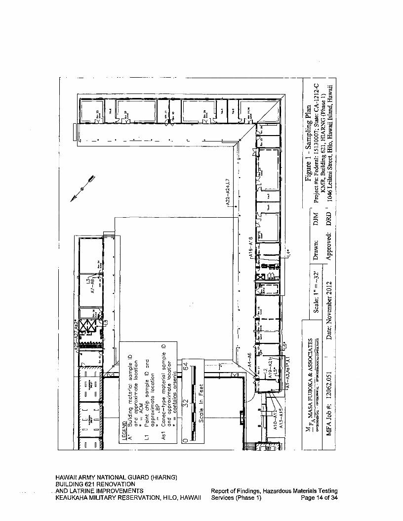
0
w
1
—I
-J
C
0) 0 0.) (I)
(N
-J
(I)
I')
Co
It
rlJ
I
rA22A
24
L7
(N m
-4
0) CO 0
U)
Dat
e: N
ovem
ber 2
012
MEA
Job
#:
HAWAII ARMY NATIONAL GUARD (HIARNG) BUILDING 621 RENOVATION AND LATRINE IMPROVEMENTS KEAUKAHA MILITARY RESERVATION, HILO, HAWAII
Report of Findings, Hazardous Materials Testing Services (Phase 1) Page 14 of 34
APPENDICES
HAWAII ARMY NATIONAL GUARD (HIARNG) BUILDING 621 RENOVATION AND LATRINE IMPROVEMENTS
Report of Findings, Hazardous Materials Testing
KEAUKAHA MILITARY RESERVATION, HILO, HAWAII Services (Phase 1) Page 15 of 34

APPENDIX A
Analytical Report - Asbestos
HAWAII ARMY NATIONAL GUARD (HIARNG) BUILDING 621 RENOVATION AND LATRINE IMPROVEMENTS Report of Findings, Hazardous Materials Testing KEAUKAHA MILITARY RESERVATION, HILO, HAWAII Services (Phase 1) Page 16 of 34

IJ;1 October 22, 2012 LABS
David Maier Masa Fujioka & Associates 98-021 Kamehameha Highway, #337 Aiea, HI 96701
INDUSTRIAL HYGIENE SERVICES
Laboratory i Man.a.m.nt 1 Training
RE: Bulk Asbestos Fiber Analysis, NVL Batch # 1216547.00
Dear Mr. Maier,
Enclosed please find test results for the bulk samples submitted to our laboratory for • analysis. Examination of these samples was conducted for the presence of identifiable
asbestos fibers using polarized light microscopy (PLM) with dispersion staining in accordance with U.S. EPN600/M4-82-020 Test Method.
For samples containing more than one separable layer of materials, the report will include findings for each layer (labeled Layer I and Layer 2, etc. for each individual layer). The asbestos concentration In the sample Is determined by visual estimation.
For those samples with asbestos concentrations between I and 10 percent based on visual estimation, the EPA recommends a procedure known as point counting (NESHAPS, 40 CFR Part 61). Point counting is a statistically more accurate means of quantification for samples with low concentrations of asbestos. If you would like us to further refine the concentration estimates of asbestos in these samples using point counting, please let me know.
This report is considered highly confidential and will not be released without your approval. Samples are archived for two weeks following analysis. Samples that are not retrieved by the client are discarded after two weeks.
Thank you for using our laboratory services. Please do not hesitate to call if there Is anything further we can assist you with.
Sincerely,
Nick Ly, Technical Director
1.888,NVL.LABS Enc.: Sample Results
cMb NVL Laboratories, Inc.
1.855.(685.5227) Lab Cod.: 102005.0 4708 Aurora Ave N, Seattle, WA 98103
www.nvllabs.com p 206.547.0100 1 f 206.634.1936
HAWAII ARMY NATIONAL GUARD (HIARNG) BUILDING 621 RENOVATION AND LATRINE IMPROVEMENTS
Report of Findings, Hazardous Materials Testing
KEAUKAHA MILITARY RESERVATION, HILO, HAWAII Services (Phase 1) Page 17 of 34
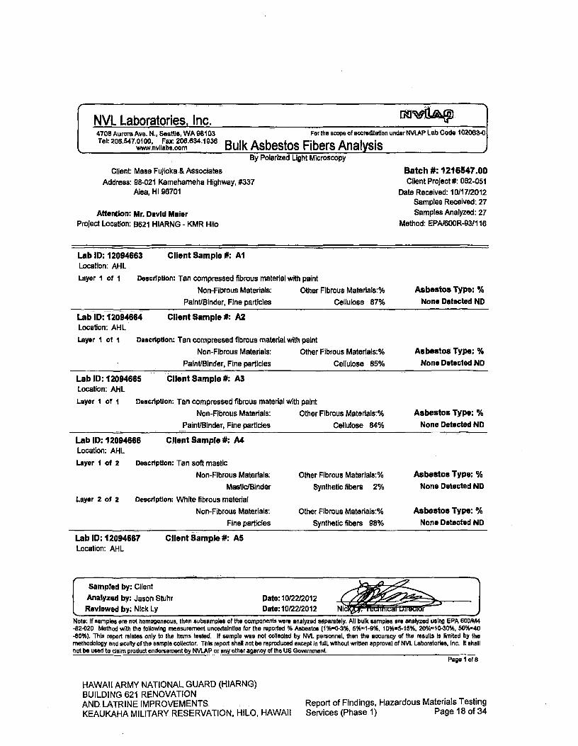
Sampled by: Client Analyzed by: Jason Stuhr Date: 10/22/2012
L Reviewed by: Nick Ly Date: 10/22/2012 Nic r
NVL Laboratories. Inc. 4708 Aurora Ave. 14., Seattle, WA 98103 For the scope of accreditation under NVLAP Lab Code 102063-0 Tel: 206.547.0100, Fax: 206.634.1936
www.nvllabs.com Bulk Asbestos Fibers Analysis By Polarized Light Microscopy
Client Mass Fujioka .& Associates Address: 98-021 Kamehameha Highway, #337
Aiea, HI 96701
Attention: Mr. David Maier Project Location: B621 HIARNG - KMR Hilo
Batch #: 1216547.00 Client Project #: 062-051
Date Received: 10/17/2012 Samples Received: 27 Samples Analyzed: 27
Method: EPAI600R-9311 16
Lab ID: 12094663 Client Sample #: Al Location: AHL
Layer I of 1 Description: Tan compressed fibrous material with paint
Non-Fibrous Materials: Other Fibrous Matenals:% Asbestos Type: %
Paint/Binder, Fine particles Cellulose 87% None Detected ND
Lab ID: 12094664 Client Sample #: A2 Location: AHL
Layer I of I Description: Tan compressed fibrous material with paint
Non-Fibrous Materials: Other Fibrous Materlals:%
Paint/Binder, Fine particles Cellulose 85%
AsbestoS Type: % None Detected ND
Lab ID: 12094665 Client Sample #: A3 Location: Al-IL
Layer I of I
Description: Tan compressed fibrous material with paint
Non-Fibrous Materials: Other Fibrous Materials:%
Asbestos Type: %
Paint/Binder, Fine particles Cellulose 84%
None Detected ND
Lab ID: 12094666 Client Sample #: A4 Location: AHL
Layer I of 2
Description: Tan soft mastic
Non-Fibrous Materials: Other Fibrous Materlals:% Asbestos Type: %
Mastic/Binder Synthetic fibers 2% None Detected ND
Layer 2 of 2
Description: White fibrous material
Non-Fibrous Materials: Other Fibrous Materials:% Asbestos Type: %
Fine particles Synthetic fibers 98% None Detected ND
Lab ID: 12094667 ClIent Sample #: AS Location: AHL
Note: If samples are not homogeneous, then subsamples of the components were analyzed separately. All bulk samples are analyzed using EPA 6001M4 -82-020 Method with the following measurement uncertainties for the reported % Asbestos (1%0-3%, 50/61-9%, 10%5-15%, 200/d10-30%, 50%=40 -60%). This report relates only to the Items tested. If sample was not collected by NVL personnel, then the accuracy of the results Is limited by the methodology and acuity of the sample collector. This report shall not be reproduced except in full, without written approval of NVL Laboratories, Inc. It shall not be used to claim product endorsement by NVLAP or any other agency of the US Government.
Page 1 of 8
HAWAII ARMY NATIONAL GUARD (HIARNG) BUILDING 621 RENOVATION AND LATRINE IMPROVEMENTS. KEAUKAHA MILITARY RESERVATION, HILO, HAWAII
Report of Findings, Hazardous Materials Testing
Services (Phase 1) Page 18 of 34

Sampled by: Client ,
Analyzed by: Jason Stuhr Date: 10/22/2012 Reviewed by: Nick Ly Date: 10/22f2012 Ni
rector
NVL Laboratories, Inc. 4708 Aurora Ave. N., Seattle, WA 98103 For the scope of accreditation under NVLAP Lab Code 102063-0 Tel: 20 6.547.0100, Fax:206.634.1936
www.nvliabs.com Bulk Asbestos Fibers Analysis By Polarized Light Microscopy
Client Masa Fujioka & Associates Address: 98-021 Kamehameha Highway, #337
Aiea, HI 96701
Attention: Mr. David Maier Project Location: B621 HIARNG - KMR Hilo
Batch #: 1216547.00 Client Project #: 062-051
Date Received: 10/17/2012 Samples Received: 27 Samples Analyzed: 27
Method: EPA/600R-93/1 16
Layer I of 2 Description: Tan soft mastic
Non-Fibrous Materials: Other Fibrous Matenals:% Asbestos Type: %
Mastic/Binder None Detected ND None Detected NO
Layer 2 of 2 Description: White fibrous material
Non-Fibrous Materials: Other Fibrous Materials:% Asbestos Type: %
Fine particles Synthetic fibers 98% None Detected NO
Lab ID: 12094668 Client Sample #: AS Location: AHL
Layer I of 2
Layer 2 of 2
Description: Tan soft mastic
Non-Fibrous Materials: Other Fibrous Materials:%
Mastic/Binder Synthetic fibers 3%
Description: White fibrous material
Non-Fibrous Materials: Other Fibrous Materials:%
Fine particles Synthetic fibers 98%
Asbestos Type: %
None Detected ND
Asbestos Type: %
None Detected ND
Lab ID: 12094669 Client Sample #: Al Location: AHL
Layer I of 2 Description: White vinyl tile
Non-Fibrous Materials: Other Fibrous Materials:% Asbestos Type: %
Vinyl/Binder None Detected ND None Detected ND
Layer 2 of 2
Description: Tan soft mastic
Non-Fibrous Materials: Other Fibrous Materials:% Asbestos Type: ¼
Mastic/Binder Cellulose 3% None Detected ND
Lab ID: 12094670 Client Sample #: A8 Location: AHL
Note: if samples are not homogeneous, then subsamples of the components were analyzed separately. All bulk samples are analyzed using EPA 6001M4 -82-020 Method with the following measurement uncertainties for the reported % Asbestos (11Y60-3016, 5%1-9% 10%"5-15%, 20%10-30°h, 50%"40 -60%). This report relates only to the items tested. If sample was not collected by NVL personnel, then the accuracy of the results is limited by the methodology and acuity of the sample collector. This report shall not be reproduced except in full, without written approval of NVL Laboratories, Inc it shall not be used to claim product endorsement by NVLAP or any other agency of the US Government.
Page 2 of 8
HAWAII ARMY NATIONAL GUARD (HIARNG) BUILDING 621 RENOVATION AND LATRINE IMPROVEMENTS
Report of Findings, Hazardous Materials Testing
KEAUKAHA MILITARY RESERVATION, HILO, HAWAII Services (Phase 1) Page 19 of 34

- Dav"f NVL Laboratories, inc. . ....... .... ... . 4708 Aurora Ave. N., Seattle, WA 98103 For the scope of accreditation under NVLAP Lab Code 102063-0 Tel: 206.547.0100, Fax: 206.634.1936
www.nvliabs.com Bulk Asbestos Fibers Analysis By Polarized Light Microscopy
Client: Masa Fujioka & Associates
Address: 98-021 Kamehameha Highway, #337 Aiea, HI 96701
Attention: Mr. David Maier Project Location: B621 HIARNG - KMR Hilo
Batch #: 1216547.00 Client Project #: 062-051
Date Received: 10117/2012 Samples Received: 27 Samples Analyzed: 27
Method: EPAI600R-93/1 16
Layer I of 2 Description: White vinyl tile
Non-Fibrous Materials: Other Fibrous Materlals:% Asbestos Type: %
Vinyl/Binder None Detected ND None Detected ND
Layer 2 of 2 Description: Tan soft mastic
Non-Fibrous Materials: Other Fibrous Materials:% Asbestos Type: %
Mastic/Binder Cellulose 2% None Detected ND
Lab ID: 12094671 Client Sample #: A9 Location: AHL
Layer I of 2 Description: White vinyl tile
Non-Fibrous Materials: Other Fibrous Materials:% Asbestos Type: %
Vinyl/Binder None Detected ND None Detected ND
Layer 2 of 2
Description: Tan soft mastic
Non-Fibrous Materials: Other Fibrous Materials:% Asbestos Type: %
Mastic/Binder None Detected ND None Detected ND
Lab ID: 12094672 Client Sample #: Al 0 Location: AHL
Layer I of I
Description: Tan/white soft material
Non-Fibrous Materials: Other Fibrous Materials:% Asbestos Type: %
Caulking compound, Paint, Fine particles None Detected ND None Detected ND
Lab ID: 12094673 Client Sample #: All Location: AHL
Layer I of I Description: Tan/white soft material
Non-Fibrous Materials:
Caulking compound, Paint, Fine particles
Other Fibrous Materials:%
None Detected ND
Asbestos Type: %
None Detected ND
Lab ID: 12094674 Client Sample #: Al2 Location: AHL
Sampled by: Client
Analyzed by: Jason Stuhr
Reviewed by: Nick Ly
Note: If samples are not homogeneous, then subsarnples of the components were analyzed separately. All bulk samples are analyzed using EPA 6001M4 -82-020 Method with the following measurement uncertainties for the reported % Asbestos (110A0-3%, 50/0=1-90%, 10%5-15%, 201/16=10-30%, 500/640 -60%). This report relates only to the items tested. If sample was not collected by NVL personnel, then the accuracy of the results Is limited by the methodology and acuity of the sample collector. This report shall not be reproduced except In full, without written approval of NVL Laboratories, Inc. It shall not be used to claim product endorsement by NVLAP or any other agency of the US Government.
Page 3 of 8
HAWAII ARMY NATIONAL GUARD (HIARNG) BUILDING 621 RENOVATION AND LATRINE IMPROVEMENTS
Report of Findings, Hazardous Materials Testing
KEAUKAHA MILITARY RESERVATION, HILO, HAWAII Services (Phase 1) Page 20 of 34

4708 Aurora Ave. N., Seattle, WA 98103 Tel: 206.547.0100, Fax: 206.634.1936
www.nvliabs.com
For the scope of accreditation under NVLAP Lab Code 102063-0
ulk Asbestos Fibers, Analysis .1
p
NVL Laboratories, Inc.
By Polarized Light Microscopy
Client: Masa Fujioka & Associates Address: 98-021 Kamehameha Highway, #337
Alea, HI 96701
Attention: Mr. David Maier Project Location: B621 H1ARNG - KMR Hilo
Batch #: 1216547.00 Client Project* 062-051
Date Received: 10/17/2012 Samples Received: 27 Samples Analyzed: 27
Method: EPAI600R-9311 16
Layer I of I Description: Tan/white soft material
Non-Fibrous Materials:
Caulking compound, Paint, Fine particles
Other Fibrous Matenals:% Asbestos Type: %
Cellulose 2% None Detected NO
Description: Whiteltan soft material
Non-Fibrous Materials:
Caulking compound, Fine particles
Lab ID: 12094675 Location: AHL
Layer I of I
Client Sample #: A13
Other Fibrous Matenals:% Asbestos Type: %
None Detected ND None Detected ND
Lab ID: 12094676 Location: AHL
Layer I of I
Client Sample #: A14
Description: White/tan soft material
Non-Fibrous Materials:
Caulking compound, Fine particles
Other Fibrous Materials:% Asbestos Type: %
Cellulose 2% None Detected NO
Lab ID: 12094677 Location: AHL
Layer I of I
Client Sample #: A15
Non-Fibrous Materials:
Caulking compound, Fine particles
Other Fibrous Materials:% Asbestos Type: %
None Detected ND None Detected ND
Description: White/tan soft material
Lab ID: 12094678 Location: AHL
Layer I of I
Client Sample #: A16
Description: Gray brittle material
Non-Fibrous Materials:
Caulking compound, Paint
Other Fibrous Materials:% Asbestos Type: %
None Detected ND None Detected ND
Lab ID: 12094679 Client Sample #: A17 Location: AHL
Sampled by: Client
Analyzed by: Jason Stuhr Reviewed by: Nick Ly
Date: 10/22/2012 Date: 10/22/2012
Note: If samples are not homogeneous, then subsamples of the components were -82-020 Method with the following measurement uncertainties for the reported % -60%). This report relates only to the Items tested. If sample was not collected methodology and acuity of the sample collector. This report shall not be reproduced not be used to claim product endorsement by NVLAP or any other agency of the us
analyzed separately. All bulk samples are analyzed using EPA 6001M4 Asbestos (1%0.3%, 5%=1-9%, 10%=5-15%, 20%=10-30%, 500/6=40 by NVL personnel, then the accuracy of the results Is limited by the except In full, without written approval of NVL Laboratories, inc. It shall Government.
Page 4 of 8
HAWAII ARMY NATIONAL GUARD (HIARNG) BUILDING 621 RENOVATION AND LATRINE IMPROVEMENTS
Report of Findings, Hazardous Materials Testing
KEAUKAHA MILITARY RESERVATION, HILO, HAWAII Services (Phase 1) Page 21 of 34

Lab ID: 12094682 Location: AHL
Layer I of I
Client Sample #: A20
Description: Gray brittle material
Sampled by: Client Analyzed by: Jason Stuhr Reviewed by: Nick Ly
Date: 10/22/2012 Date: 10/22/2012 p Ni irec
NVL Laboratories, Inc. 4708 Aurora Ave. N. Seattle, WA 98103 Tel: 206.547.0100, Fax: 206.634.1938
www.nvllabs.com
For the scope of accreditation under NVLAP Lab Code 102063-0
Bulk Asbestos Fibers Analysis I By Polarized Light Microscopy
Client: Masa Fujioka & Associates Address: 98-021 Kamehameha Highway, #337
Aiea, HI 96701
Attention: Mr. David Maier Project Location: B621 HIARNG - KMR Hilo
Batch #: 1216547.00 Client Project #: 062-051
Date Received: 10/17/2012 Samples Received: 27 Samples Analyzed: 27
Method: EPA/600R-93/116
Layer I of I Description: Gray brittle material
Non-Fibrous Materials:
Caulking compound, Paint
Other Fibrous Materiais:% Asbestos Type: %
Cellulose 3% None Detected ND
Lab ID: 12094680 Client Sample #: A18 Location: AHL
Layer I of I Description: Gray brittle material
Non-Fibrous Materials:
Caulking compound, Paint
Other Fibrous Matenals:% Asbestos Type; %
Cellulose 2% None Detected ND
Lab ID: 12094681 Client Sample #: A19 Location: AHL
Layer I of I Description: Gray brittle material
Non-Fibrous Materials:
Caulking compound, Paint.
Other Fibrous Materials:% Asbestos Type: %
Spider silk 2% None Detected ND
Non-Fibrous Materials:
Other Fibrous Materiais:% Asbestos Type: %
Caulking compound, Paint
None Detected ND None Detected ND
Lab ID: 12094683 Client Sample #: A21 Location: AHL
Layer I of I Description: Gray brittle material
Non-Fibrous Materials:
Caulking compound, Paint
Other Fibrous Materlals:% Asbestos Type; %
Spider silk 3% None Detected ND
Lab ID: 12094684 Client Sample #: A22 Location: AHL
Note: if samples are not homogeneous, then subsamples of the components were -82-020 Method with the following measurement uncertainties for the reported % -60*4 This report relates only to the items tested. it sample was not collected methodology and acuity of the sample collector. This report shall not be reproduced not be used to claim product endorsement by NVLAP or any other agency of the US
analyzed separately. All bulk samples are analyzed using EPA 600/M4 Asbestos (1%0-3%, 5%1-91,16, 10%5-15%, 20%10-300A, 50%=40 by NVL personnel, then the accuracy of the results is limited by the except In full, without written approval of NVL Laboratories, Inc. It shall Government.
Page 5 of 8
HAWAII ARMY NATIONAL GUARD (HIARNG) BUILDING 621 RENOVATION AND LATRINE IMPROVEMENTS KEAUKAHA MILITARY RESERVATION, HILO, HAWAII
Report of Findings, Hazardous Materials Testing Services (Phase 1) Page 22 of 34
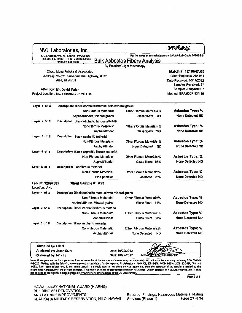
Description: Black asphaltic material with mineral grains
Non-Fibrous Materials:
Asphalt/Binder, Mineral grains
Description: Black asphaltic fibrous material
Non-Fibrous Materials:
Asphalt/Binder
Description: Black asphaltic material
Non-Fibrous Materials:
Asphalt/Binder
Description: Black asphaltic fibrous material
Non-Fibrous Materials:
Asphalt/Binder
Description: Tan fibrous material
Non-Fibrous Materials:
Fine particles
Layer I of 5
Layer 2 of 5
Layer 3 of 5
Layer 4 of 5
Layer 5 of 5
Other Fibrous Materials:%
Glass fibers 9%
Other Fibrous Materlals:%
Glass fibers 70%
Other Fibrous Materials-.%
None Detected ND
Other Fibrous Materials:%
Glass fibers 65%
Other Fibrous Materials:%
Cellulose 980A
Asbestos Type: % None Detected ND
Asbestos Type: %
None Detected NO
Asbestos Type: % None Detected ND
Asbestos Type: %
None Detected NO
Asbestos Type: %
None Detected NO
Sampled by: Client Analyzed by: Jason Stuhr Date: 10/22/2012 Reviewed by: Nick Ly Date: 10122/2012 Nic
owl
p
NVL Laboratories, Inc. 4708 Aurora Ave. N., Seattle, WA 98103 For the scope of accreditation under NVLAP Lab Code 102063-0 Tel: 206.547.0100, Fax: 206.634.1936
www.nvflabs.com ulk Asbestos Fibers Analysis I By Polarized Light Microscopy
Client: Masa Fujioka & Associates Address: 98-021 Kamehameha Highway, #337
Ala, HI 96701
Attention: Mr. David Maier Project Location: 8621 HIARNG - KMR 1-1110
Batch #: 1216547.00 Client Project #: 062-051
Date Received: 10/17/2012 Samples Received: 27 Samples Analyzed: 27
Method: EPA/600R-93/1 16
Lab ID: 12094685 Client Sampie#: A23 Location: AHL
Layer I Of 5 Description: Black asphaltic material with mineral grains
Layer 2 of 5
Layer 3 of 5
Non-Fibrous Materials:
Asphalt/Binder, Mineral grains
Description: Black asphaltic fibrous material
Non-Fibrous Materials:
Asphalt/Binder
Description: Black asphaltic material
Non-Fibrous Materials:
Asphalt/Binder
Other Fibrous Materlals:%
Glass fibers 11%
Other Fibrous Materials:%
Glass fibers 68%
Other Fibrous Materials:%
None Detected ND
Asbestos Type: %
None Detected ND
Asbestos Type: %
None Detected ND
Asbestos Type: %
None Detected ND
Note: If samples are not homogeneous, then subsamples of the components were analyzed separately. All bulk samples are analyzed using EPA 600/M4 -82-020 Method with the following measurement uncertainties for the reported % Asbestos (1%0-3%, 5%19% 10%=5-15%, 20%=10-30%, 50%=40 -60%). This report relates only to the Items tested. If sample was not collected by NVL personnel, then the accuracy of the results Is limited by the methodology and acuity of the sample collector. This report shall not be reproduced except in full, without written approval of NVL Laboratories, Inc. It shall not be used to claim product endorsement by NVLAP or any other agency of the US Government
Page 6 of 8
HAWAII ARMY NATIONAL GUARD (HIARNG) BUILDING 621 RENOVATION AND LATRINE IMPROVEMENTS
Report of Findings, Hazardous Materials Testing
KEAUKAHA MILITARY RESERVATION, HILO, HAWAII Services (Phase 1) Page 23 of 34

NVL Laboratories, Inc. 4708 Aurora Ave. N., Seattle, WA 98103 For the scope of accreditation under NVLAP Lab Code 102063-0 Tel: 206.547.0100, Fax: 206.634.1936
www.nvllabs.com ulk Asbestos Fibers Analysis I
(
By Polarized Light Microscopy
Client: Masa Fujioka & Associates Address: 98-021 Kamahameha Highway, #337
Aiea, HI 96701
Attention: Mr. David Maier Project Location: B621 HIARNG - KMR Hilo
Batch #: 1216547.00 Client Project* 062-051
Date Received: 10/17/2012 Samples Received: 27 Samples Analyzed: 27
Method: EPAI600R-93/1 16
Layer 4 of 5
Layer 5 of 5
Description: Black asphaltic fibrous material
Non-Fibrous Materials:
Asphalt/Binder
Description: Tan fibrous material
Non-Fibrous Materials:
Fine particles
Other Fibrous Materlals:% Asbestos Type: %
Glass fibers 63% None Detected ND
Other Fibrous Matorials:% Asbestos Type: %
Cellulose 97% None Detected ND
Lab ID: 12094686 Client Sample #: A24 Location: AHL
Layer I of 5 Description: Black asphaltic material with mineral grains
Layer 2 of 5
Layer 3 of 5
Layer 4 of 5
Layer 5of5
Non-Fibrous Materials:
Asphalt/Binder, Mineral grains
Description: Black asphaltic fibrous material
Non-Fibrous Materials:
Asphalt/Binder
Description: Black asphaltic material
Non-Fibrous Materials:
Asphalt/Binder
Description: Black asphaltic fibrous material
Non-Fibrous Materials:
Asphalt/Binder
Description: Tan fibrous material
Non-Fibrous Materials:
Fine particles
Other Fibrous Materials:%
Asbestos Type: %
Glass fibers 10%
None Detected ND
Other Fibrous Materials:% Asbestos Type: %
Glass fibers 71% None Detected NO
Other Fibrous Materlals:%
Asbestos Type: %
None Detected ND
None Detected NO
Other Fibrous Materiais:%
Asbestos Type: %
Glass fibers 70%
None Detected ND
Other Fibrous Materials:%
Asbestos Type: %
Cellulose 98%
None Detected ND
Lab ID: 12094687 Client Sample #: A25 Location: AHL
Sampled by: Client Analyzed by: Jason Stuhr Date: 10/2212012 Reviewed by: Nick Ly Date: 10/22/2012 Nick
11 - -!w- - 1 7
I
Note: If samples are not homogeneous, then subsamples of the components were analyzed separately. All bulk samples are analyzed using EPA 600/TM -82-020 Method with the following measurement uncertainties for the reported % Asbestos (1%=0-3%, 50/01-9% 10%'5-15% 20%10-30%, 50%-40 -60%). This report relates only to the Items tested. If sample was not collected by NVL personnel, then the accuracy of the results Is limited by the methodology and acuity of the sample collector. This report shall not be reproduced except in full, without written approval of NVL Laboratories, Inc. it shall not be used to claim product endorsement by NVLAP or any other agency of the US Government.
Page 7 of 8
HAWAII ARMY NATIONAL GUARD (H1ARNG) BUILDING 621 RENOVATION AND LATRINE IMPROVEMENTS
Report of Findings, Hazardous Materials Testing
KEAUKAHA MILITARY RESERVATION, HILO, HAWAII Services (Phase 1) Page 24 of 34

"S
NVL Laboratories, Inc. 4708 Aurora Ave. N., Seattle, WA 98103 For the scope of accreditation uriderNVLAP Lab Code 102083-0 Tel: 206.547.0100, Fax: 208634.1936
www.nvllabs.com Bulk Asbestos Fibers Analysis
'F
By Polarized Light Microscopy
Client Masa Fujioka & Associates Batch #: 1216547.00
Address: 98-021 Kamehameha Highway, #337
Client Project #: 062-051 Alea, HI 96701
Date Received: 10117/2012 Samples Received: 27
Attention: Mr. David Maler Samples Analyzed: 27
Project Location: B621 HIARNG - KMR Hilo Method: EPA/600R-93/1 16
Layer I of I
Description: Tan compressed fibrous material with paint
Non-Fibrous Materials: Other Fibrous Materlals:%
Asbestos Type: %
Paint/Binder, Fine particles Cellulose 80%
None Detected ND
Lab ID: 12094688 Client Sample #: A26 Location: AHL
Layer I of I Description: Tan compressed fibrous material with paint
Non-Fibrous Materials: Other Fibrous Materlals:%
Paint/Binder, Fine particles Cellulose 82%
Asbestos Type: %
None Detected ND
Lab ID: 12094689 Client Sample #: A27 Location: 8621 HIARNG - KMR Hilo
Layer I of I Description: Tan compressed fibrous material with paint
Non-Fibrous Materials: Other Fibrous Materials:%
Paint/Binder, Fine particles Cellulose 85%
Asbestos Type: %
None Detected ND
Sampled by: Client Analyzed by: Jason Stuhr Date: 10122/2012 Reviewed by: Nick Ly Date: 10122/2012 Ni
Note: If samples are not homogeneous, then subsamples of the components were analyzed separately. All bulk samples are analyzed using EPA 600/M4 -82-020 Method with the following measurement uncertainties for the reported % Asbestos (1%=0-3%, 5%=1-9%, 10%'5-15%, 200/6=10-30%, 50%40 .60%). This report relates only to the items tested. If sample was not collected by NVL personnel, then the accuracy of the results Is limited by the methodology and acuity of the sample collector. This report shall not be reproduced except in full, without written approval of NVL Laboratories, Inc. it shell not be used to claIm product endorsement by NVLAP or any other agency of the US Government.
Page 8 of 8
HAWAII ARMY NATIONAL GUARD (HIARNG) BUILDING 621 RENOVATION AND LATRINE IMPROVEMENTS
Report of Findings, Hazardous Materials Testing
KEAUKAHA MILITARY RESERVATION, HILO, HAWAII Services (Phase 1) Page 25 of 34

AIG-oMt L
Dateflme; lo
Date[flme: t11P2f 4&;Lao~
41kf' Samples Released B Date/lime:/O-? -I?- _
Samples Releedy: 4'
Samples
B:
C'
OCT. 23. 2012 10:41AM NVLLABS SEATAC NO. 5425 P.4
MSA HJflOKA & ASSOCIATES -. BATCH ID Bulk Sample Data Sheet (Asbestos)
Please email results to: [email protected] 1216547oOO ANALYZE TO FIRST POSITVE /5 DAY TAT
PROJECT NAME: '(3(,( U 11(Q PROJECT NO: 1 "Z
LOCATION:JMr- I4jcL IN5PECTOTh
DATE: /O IS ('L.- PAGE: OF
SAMPLE NO HM# MA AL LOCAI1ON CAIGORY (Macs/rs') FRPASIUIY QUANTiTY
Alf—ft. Ab
yo"
Y-gr
r-
Aio-AZ ',~
O&VOC
wxwwow (4 C) 1r41 c,L -0 rum d alq As%,-wk re, 2.0
VIP.
C,. I'
rujrL Ir.
y1 I I% t~~ ( fLPe&4A4
06 ww~. . 77 q-0
06
00 (ci loom (3fl31) SaanipIes— 1,OOQ.,OIP N eump1ea--6OOOfi7ttx7ff) 0 7 samPles)
Samples Analyzed By: - __Date/11m
HAWAII ARMY NATIONAL GUARD (HIARNG) BUILDING 621 RENOVATION AND LATRINE IMPROVEMENTS KEAUKAHA MILITARY RESERVATION, HILO, HAWAII
Report of Findings, Hazardous Materials Testing Services (Phase 1) Page 26 of 34

APPENDIX B
Analytical Report - Lead
HAWAII ARMY NATIONAL GUARD (HIARNG) BUILDING 621 RENOVATION AND LATRINE IMPROVEMENTS
Report of Findings, Hazardous Materials Testing
KEAUKAHA MILITARY RESERVATION, HILO, HAWAII Services (Phase 1) Page 27 of 34

Nick Ly, Technical Director
1.8SLNVL,LABS 1.888.685.5227) www.nvliabs.com
Enclosure:
October 23, 2012
David Maier Masa Fujioka & Associates 98-021 Kamehameha Highway, #337 Aiea, HI 96701
IN DUST RIA L HV ro IENE SERVICES
Laboratory I MaflDmflt I Tra1nInj
RE: Metals Analysis; NVL Batch # 1216548.00
Dear Mr. Maier,
Enclosed please find the test results for samples submitted to our laboratory for analysis. Preparation of these samples was conducted following protocol outlined In EPA Method SW 846-3051 unless stated otherwise. Analysis of these samples was performed using analytical instruments in accordance with U.S. EPA, NIOSH, OSHA and other ASTM methods.
For matrix materials submitted as paint dust wipe, soil or TCLP samples, analysis for the presence of total metals is conducted using published U.S. EPA Methods. Paint and soil results are usually expressed In mg/Kg which is equivalent to parts per million (ppm). Lead (Pb) in paint Is usually expressed in mg/Kg (ppm), Percent (%) or mg/cm2 by area. Dust wipe sample results are usually expressed In ug/wipe and ug/ft2. TCLP samples are reported In mg/L (ppm). For air filter samples, analyses are conducted using NIOSH and OSHA Methods. Results are expressed in ug/filter and uglm3. Other matrix materials are analyzed accordingly using published methods or specified by client The reported test results pertain only to Items tested. Lead test results are not blank corrected.
For recent regulation updates pertaining to current regulatory levels or permissible exposure levels, please call your local regulatory agencies for more details.
This report is considered highly confidential and will not be released without your approval. Samples are archived for two weeks following analysis. Samples that are not retrieved by the client are discarded after two weeks.
Thank you for using our laboratory services, if you need further assistance please feel free to call us at 206-547-0100 or 1-888-NVLLABS.
Sincerely,
NVL Laboratories, Inc.
4708 Aurora Ave N, Seattle, WA.98.103
p 206.547.0100 f 206.634.1936
HAWAII ARMY NATIONAL GUARD (HIARNG) BUILDING 621 RENOVATION AND LATRINE IMPROVEMENTS
Report of Findings, Hazardous Materials Testing
KEAUKAHA MILITARY RESERVATION, HILO, HAWAII Services (Phase 1) Page 28 of 34
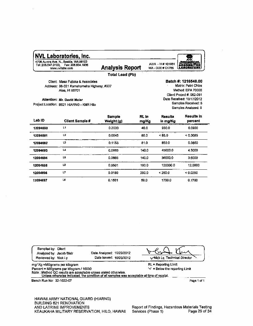
NVL Laboratories, Inc. 4708 Aurora Ave. N.1 Seattle, WA 98103 Tel: 206.547.0100, Fax: 206634.1936
www.nvllabs.com AIHA -iI-I# 101861
Analysis Report . WA - DOE# C1 765
Batch #: 1216548.00 Matrix: Paint Chips
Method: EPA 7000B Client Project #: 062-051
Date Received: 10/17/2012 Samples Received: B Samples Analyzed: 8
Client Masa Fujioka & Associates Address: 98-021 Kamehameha Highway, #337
Aiea, Hi 96701
Attention: Mr. David Maler Project Location: B621 HIARNG - KMR Hilo
Sample RL In Results Results in Client Sample # Weight(g) mg/Kg In mg/Kg percent Lab ID
HAWAII ARMY NATIONAL GUARD (HIARNG) BUILDING 621 RENOVATION AND LATRINE IMPROVEMENTS KEAUKAHA MILITARY RESERVATION, HILO, HAWAII
Report of Findings, Hazardous Materials Testing Services (Phase 1) Page 29 of 34
Total Lead (Pb)
- Sampled by: Client Analyzed by: Jacob Blair Date Analyzed: 10/23/2012
Reviewed by: Nick Ly Date Issued: 10/23/2012 v-Nick Ly, Technical Director "
mg/ Kg =Milligrams per kilogram RL = Reporting Limit Percent = Milligrams per kilogram / 10000 '<' = Below the reporting Limit Note: Method QC results are acceptable unless stated otherwise.
Unless otherwise Indicated, the condition of all samples was acceptable at time of receipt. Bench Run No: 32-1022-07 Page 1 of I
Ll i
12094690 LI
0.2033
46.0 950.0 0.0950
12094691 12 0.0545
85.0 <85.0 <0.0085
12094692 L3 0.1153
81.0 850.0 0.0850
12094693 14
0.0663
140.0 45000.0 4.5000
12094694 L5
0.0665
140.0 36000.0 3.6000
12094695 L6
00501
190.0 120000.0 12.0000
12094696 L7 0.0189
250.0 <250.0 <0.0250
12094697 L8
0.1561
59.0 1700.0 0.1700
AlHP
ACORIDITSO LARORATORY

PROJECT NAME:
LOCATION:
CLIENT:
PROJECT NO: Y:~ /Z-71- 05- ( Q-! 1P4W4, INSPECTOR: KA/g L-~
DATE: IO-(Z VI—
%w %
"e, 1Ak '&~-(
L Al
1.300 Date/lime: L017/121 fO
MASA FUJIOICA & ASSOCIATES Bulk Sample Data Sheet (Lead)
Please email results to: [email protected] 5 DAY TAT
BATCH ID
1216548.00
SAMPLE NO. COLOR 5UD5TRATE COMPONENT LOCATION CONDITION QUANTITY
rw,IO I'.. I C44'Jc-
1k Ca,c.CaJL
1-5 &1it Cv&
LJf - a i1a ~ W~-~ j;JJ).%) Jr---
0.;46 rv--4
(C
L1 1 MA4Z. i — tNsk(l)
r.. t- i-;th
(&.4 1 k7) Afc
'I Ykit
Samples Released By: t' V
Samples ReIeeed By:
Samples Released By:
Z4 C*~6 Samples Analyzed By: L t
ttAA Date/Time: /0I5- ?'2.
dapte/Time:
to\flv1 oc1
Date/Time:
HAWAII ARMY NATIONAL GUARD (HIARNG) BUILDING 621 RENOVATION AND LATRINE IMPROVEMENTS KEAUKAHA MILITARY RESERVATION, HILO, HAWAII
V, i%-. 550p,
1~41
Report of Findings, Hazardous Materials Testing Services (Phase 1) Page 30 of 34

APPENDIX C
Analytical Report - Arsenic
HAWAII ARMY NATIONAL GUARD (HIARNG) BUILDING 621 RENOVATION AND LATRINE IMPROVEMENTS
Report of Findings, Hazardous Materials Testing
KEAUKAHA MILITARY RESERVATION, HILO, HAWAII Services (Phase 1) Page 31 of 34
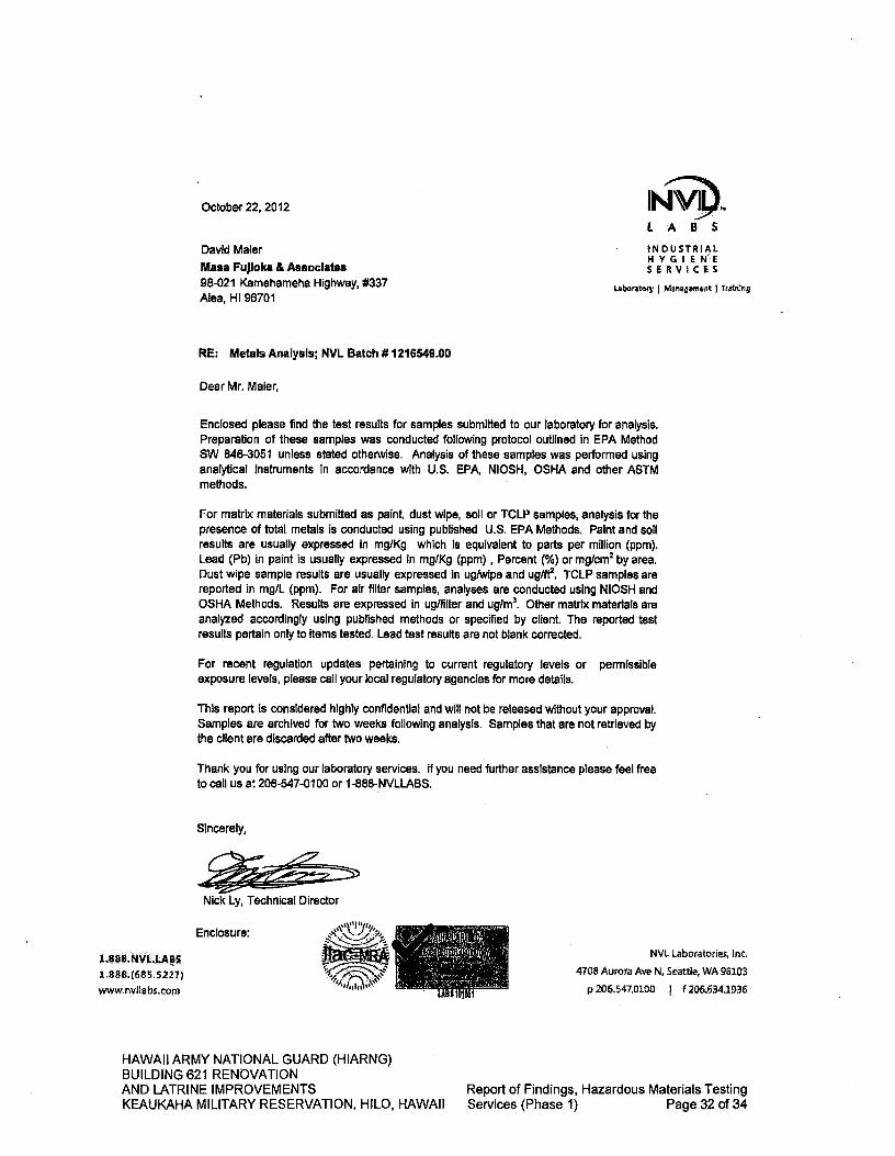
Nick Ly, Technical Director
1.888.NVLLABS 1.888.(685.5227) www.nvllabs.com
Enclosure:
October 22, 2012
LABS
David Maier Maca Fujioka & Associates 98-021 Kamehameha Highway, #337 Aiea, HI 96701
INDUSTRIAL HYGIENE SERViCES
Laboratory I Management I Trn1ng
RE: Metals Analysis; NVL Batch # 1216549.00
Dear Mr. Maier,
Enclosed please find the test results for samples submitted to our laboratory for analysis. Preparation of these samples was conducted following protocol outlined in EPA Method SW 646-3051 unless stated otherwise. Analysis of these samples was performed using analytical instruments in accordance with U.S. EPA, NIOSH, OSHA and other ASTM methods.
For matrix materials submitted as paint, dust wipe, soil or TCLP samples, analysis for the presence of total metals is conducted using published U.S. EPA Methods. Paint and soil results are usually expressed in mg/Kg which Is equivalent to parts per million (ppm). Lead (Pb) in paint is usually expressed in mg/Kg (ppm), Percent (%) or mg/cm2 by area. Dust wipe sample results are usually expressed in uglwipe and ug/ft2. TCLP samples are reported In mg/L (ppm). For air filter samples, analyses are conducted using NIOSH and OSHA Methods. Results are expressed In ug/filter and ug/m3. Other matrix materials are analyzed accordingly using published methods or specified by client. The reported test results pertain only to items tested. Lead test results are not blank corrected.
For recent regulation updates pertaining to current regulatory levels or permissible exposure levels, please call your local regulatory agencies for more details.
This report is considered highly confidential and will not be released without your approval. Samples are archived for two weeks following analysis. Samples that are not retrieved by the client are discarded after two weeks.
Thank you for using our laboratory services, if you need further, assistance please feel free to call us at 206-547-0100 or 1-888-NVLLABS.
Sincerely,
NVL Laboratories, Inc.
4708 Aurora Ave N Seattle, WA 98103 p 205.547.0100 f 206.634.1936
HAWAII ARMY NATIONAL GUARD (HIARNG) BUILDING 621 RENOVATION AND LATRINE IMPROVEMENTS
Report of Findings, Hazardous Materials Testing
KEAUKAHA MILITARY RESERVATION, HILO, HAWAII Services (Phase 1) Page 32 of 34
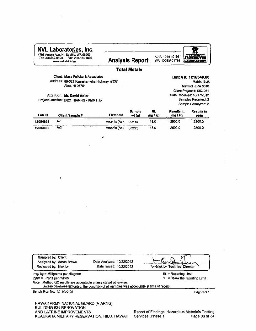
NVL Laboratories, Inc. 4708 Aurora Ave. N., Seattle, WA 98103 Tel: 206.547.0100, Fax: 206.634.1936
www.nvllabs.com
AIHA -IH#101861 Analysis Report WA - DOE # C1 765
Ml 18.0 2800.0 2800.0 Arsenic (As) 0.2187 12094698
As2 Arsenic (As) 0.2225 18.0 2500.0 2500.0 12094699
Sampled by: Client Analyzed by: Aaron Brown Reviewed by: Nick Ly
Date Analyzed: 10/22/2012
Date Issued: 10/22/2012 'Y-Njck Lv, Tec nical Director
Total Metals Client: Masa Fujioka & Associates
Address: 98-021 Kamehameha Highway, #337 Abe, HI 96701
Attention: Mr. David Maier Project Location: B621 HIARNG - KMR Hilo
Batch #: 1216549.00 Matrix: Bulk
Method: EPA 6010 Client Project #: 062-051
Date Received: 10/1712012 Samples Received: 2
Samples Analyzed: 2
Sample RL Results in Results In Lab ID Client Sample it Elements wt (g) mg (kg mg kg ppm
Mgt kg = Milligrams per kilogram
RI = Reporting Limit ppm = Parts per million
= Below the reporting Limit
Note: Method QC results are acceptable unless stated otherwise. Unless otherwise indicated, the condition of all samples was acceptable at time of receipt.
Bench Run No: 32-1022-01
HAWAII ARMY NATIONAL GUARD (HIARNG) BUILDING 621 RENOVATION AND LATRINE IMPROVEMENTS KEAUKAHA MILITARY RESERVATION, HILO, HAWAII
Page 1 of I
Report of Findings, Hazardous Materials Testing Services (Phase 1) Page 33 of 34

PROJECT NAME: PROJECT NO: OL ,r7 OT(
LOCATION: VwL &z W 1 INSPECTOR: A
DATE: CLIENT: At4-'--- PAGE: ( OF (
ik Samples Released B Date/Time:
5•
Samples By:
o-15 2- Date/Time: toill)
Date/Time:
Date/Time:
Samples Released By:
Samples Analyzed By:
MASA FUJIOKA & ASSOCIATES 13u11 Sample Data Sheet (A.to) Arevt
Please email results to: [email protected] ANALYZE TO FIRST POSJTVE /5 DAY TAT
BATCH ID
1216549,00
CATEGORY QUANTITY (M/SflSI) SAMPLE NO. HM# MATERIAL DESCRIPTION LOCATION
FRIABILITY
(IL) 041~bt ILLdb
ft A
r'' 4 rw IC)
i4O
jc1,0001t2 (31'41) = 3 samples- 1,000ft1- 5,00W= 5 samples- >5000ft(7009) = 7 samples)
HAWAII ARMY NATIONAL GUARD (HIARNG) BUILDING 621 RENOVATION AND LATRINE IMPROVEMENTS KEAUKAHA MILITARY RESERVATION, HILO, HAWAII
Report of Findings, Hazardous Materials Testing Services (Phase 1) Page 34 of 34
REPORT OF FINDINGS HAZARDOUS MATERIALS TESTING SERVICES
Project Numbers: Federal: 15130007; State: CA-1212-C Keaukaha Military Reservation, Building 621
Hawaii Youth Challenge Academy (YCA) (Phase 2-3) 1046 Leilani Street, Hilo, Hawaii Island, Hawaii
January 25,2013
MASA FUJIOKA & ASSOCIATES Job Number 12062-057
HAWAII ARMY NATIONAL GUARD (I-IIARNG) BUILDING 621 RENOVATION AND LATRINE IMPROVEMENTS
Report of Findings, Hazardous Materials Testing
KEAUKAHA MILITARY RESERVATION, HILO, HAWAII Services (Phase 2-3) Page 1 of 34

MASA FUJIOKA & ASSOCIATES Envfronmental-, Geotechnical Hydrogeological Consultants
98-021 Kamehameha Highway, Suite 337 'Aiea, Hawaii 96701-4914 Telephone: (808) 484-5366 • Facsimile: (808) 484-0007
January 25, 2013
MFA Job No. 12062-057
Architects Hawaii, Ltd. Pacific Guardian Center, Makai Tower 733 Bishop Street, Suite 3100 Honolulu, Hawaii 96813
Attention: Mr. Lloyd T. Arakaki
Subject: Report of Findings Hazardous Materials Testing Services Project Numbers: Federal: 15130007; State: CA-1212-C Keaukaha Military Reservation, Building 621 Hawaii Youth Challenge Academy (YCA) (Phase 2-3) 1046 Leilani Street, 11110, Hawaii Island, Hawaii
Dear Mr. Arakaki:
Masa Fujioka & Associates (MFA) has performed sampling for hazardous materials at the above-referenced site. MFA collected bulk building material samples and paint chip samples in areas we understood will be affected by the planned project. The results are contained in this report. It has been a pleasure performing this service for you. Please contact the undersigned at 484-5366 or [email protected] if you have any questions regarding this report.
Respectfully submitted,
MASA FUJIOKA & ASSOCIATES A Professional Partnership
David J. Maier Hazardous Materials Project Designer
HAWAII ARMY NATIONAL GUARD (HIARNG) BUILDING 621 RENOVATION AND LATRINE IMPROVEMENTS
Report of Findings, Hazardous Materials Testing
KEAUKAHA MILITARY RESERVATION, HILO, HAWAII Services (Phase 2-3) Page 2 of 34

MASA FUJIOKA & ASSOCIATES Environmental • Geotechnical 'Hydrogeological Consultants
TABLE OF CONTENTS
LIST OF ACRONYMS iii 1.0 INTRODUCTION 1
1.1 Scope of Work 1 1.2 MFA Personnel 1
2.0 ANALYTICAL METHODS 1 2.1 Asbestos 1 2.2 Lead 2 2.3 Lighting 2 2.4 Arsenic 3
3.0 SURVEY RESULTS 3 3.1 Asbestos 3 3.2 Lead 4 3.3 Lighting 6 3.4 Arsenic 6
4.0 RECOMMENDATIONS 7 4.1 Asbestos 7 4.2 Lead 8 4.3 Lighting 9 4.4 Arsenic 9
5.0 LIMITATIONS 10
TABLES TABLE 1 Summary of Asbestos Sample Results 3 TABLE 2 Summary of Paint Chip Sample Results 5
FIGURES
FIGURE 1 Sampling Plan
APPENDICES
APPENDIX A
Analytical Report - Asbestos APPENDIX B
Analytical Report - Lead APPENDIX C
Analytical Report - Arsenic
11
HAWAII ARMY NATIONAL GUARD (HIARNG) BUILDING 621 RENOVATION AND LATRINE IMPROVEMENTS
Report of Findings, Hazardous Materials Testing
KEAUKAHA MILITARY RESERVATION, HILO, HAWAII Services (Phase 2-3) Page 3 of 34

MASA FUJIOKA & ASSOCIATES Environmental • Geotechnical • Hydrogeological Consultants
LIST OF ACRONYMS
AAS Atomic Absorption Spectroscopy ACM Asbestos-Containing Material AHERA Asbestos Hazard Emergency Response Act AIHA American Industrial Hygiene Association CDC Centers for Disease Control and Prevention CFR Code of Federal Regulations DOH Hawaii State Department of Health EAL Environmental Action Level EHE Environmental Hazard Evaluation ELLAP Environmental Lead Laboratory Accreditation Program EPA U.S. Environmental Protection Agency HAR Hawaii Administrative Rules HEER Hazard Evaluation and Emergency Response HIOSH Hawaii Occupational Safety and Health HUD U.S. Department of Housing and Urban Development LBP Lead-Based Paint LCP Lead-Containing Paint MFA Masa Fujioka and Associates ND Not detected NESHAP National Emission Standards for Hazardous Air Pollutants NIOSH National Institute for Occupational Safety and Health NVL NVL Laboratories, Inc. NVLAP National Voluntary Laboratory Accreditation Program OSHA Occupational Safety and Health Administration PCBs Polychlorinated Biphenyls PLM Polarized Light Microscopy PPE Personal Protective Equipment RACM Regulated Asbestos Containing Material TCLP Toxicity Characteristic Leaching Procedure TSCA Toxic Substance Control Act TSI Thermal System Insulation
111
HAWAII ARMY NATIONAL GUARD (HIARNG) BUILDING 621 RENOVATION AND LATRINE IMPROVEMENTS
Report of Findings, Hazardous Materials Testing
KEAUKAHA MILITARY RESERVATION, HILO, HAWAII Services (Phase 2-3) Page 4 of 34

MASA FUJIOKA & ASSOCIATES Environmental • Geotechnical . 1-lydrogeological Consultants
REPORT OF FINDINGS HAZARDOUS MATERIALS TESTING SERVICES
Project Numbers: Federal: 15130007; State: CA-1212-C Keaukaha Military Reservation, Building 621
Hawaii Youth Challenge Academy (YCA) (Phase 2-3) 1046 Leilani Street, Bib, Hawaii Island, Hawaii
1.0 INTRODUCTION
1.1 Scope of Work
Masa Fujioka and Associates (MFA) was retained by Architects Hawaii, Ltd. to perform sampling and testing services at the above-referenced project site. Our scope of work included conducting a visual survey and sampling of materials at Hawaii Youth Challenge Academy (YCA) portion of Building 621 where components and materials are expected to be disturbed. MFA sampled materials for the presence of asbestos, arsenic, and lead (in paint). Building lighting systems were visually checked to evaluate the potential presence of polychlorinated biphenyls (PCBs) and mercury.
It should be noted that Rooms 2, 4, and 5 were not accessible at the time of our visit.
1.2 MFA Personnel
Mr. David Maier visited the site and collected bulk building material samples on January 8, 2013. Mr. Maier is an Asbestos Hazard Emergency Response Act (AHERA)-accredited Asbestos Inspector and Asbestos Project Designer certified in the State of Hawaii in accordance with Hawaii Administrative Rules (HAR) Title 11, Chapter 504, Asbestos Abatement Certification Program (DOH card: HIASB-2548). Mr. Maier is also certified by the State of Hawaii as a Lead Inspector and Lead Risk Assessor in accordance with Chapter 11-41 HAR and the Toxic Substance Control Act (TSCA) Section 402 (a)(2) (DOH card: P13-0240).
2.0 ANALYTICAL METHODS
2.1 Asbestos
Thirty (3 0) bulk samples from ten (10) homogeneous suspect materials were collected in areas that we were told would be affected by the proposed project. Samples were obtained with the intent to be representative of materials a contractor may encounter during this work. Samples were submitted to NVL Laboratories, Inc. (NVL) for analysis. The following is a summary of the survey and sampling process:
• Review existing drawings • Conduct walk-through to corroborate drawings with existing conditions
Hazardous Materials Testing Services 1 MFA Project No. 12062-057 KMR B621 YCA, Hilo, HI January 25, 2013
HAWAII ARMY NATIONAL GUARD (HIARNG) BUILDING 621 RENOVATION AND LATRINE IMPROVEMENTS
Report of Findings, Hazardous Materials Testing
KEAUKAHA MILITARY RESERVATION, HILO, HAWAII Services (Phase 2-3) Page 5 of 34

MASA FUJIOKA & ASSOCIATES Environmental Geotechnical a Hydrogeologi cal Consultants
• Assess materials to be sampled • Delineate homogeneous sampling areas and develop a sampling plan • Record material/sample information onto field log • Obtain samples
NVL is a National Voluntary Laboratory Accreditation Program (NVLAP)-accredited laboratory. Their accreditation number is 102063-0 for "Bulk Asbestos Fiber Analysis." Their office is located at 4708 Aurora Avenue North, Seattle, Washington, 98103.
The samples were analyzed using polarized light microscopy (PLM) with dispersion staining according to U. S. Environmental Protection Agency (EPA) Method 6001M4-82-020. Appropriate chain-of-custody procedures were followed in submitting the samples to the laboratory.
2.2 Lead
Thirteen (13) paint chip samples were collected in areas that we were told would be affected by the proposed project. Samples were obtained with the intent to be representative of materials a contractor may encounter during this work. Testing combinations were selected by observing building component and substrate. Samples were submitted to NVL for total lead analysis. The following is a summary of the survey and sampling process:
• Review existing drawings • Conduct walk-through to corroborate drawings with existing conditions • Assess surfaces to be sampled • Delineate functional spaces, components, substrates and surface colors to develop
a sampling plan • Record material/sample information onto field log • Obtain samples
The samples were analyzed using Flame Atomic Absorption Spectrophotometiy, EPA Method SW 846-3051/7000B. NVL currently participates in the Environmental Lead Laboratory Accreditation Program (ELLAP). The ELLAP is administered by the American Industrial Hygiene Association (AIHA) in cooperation with the Centers for Disease Control and Prevention (CDC), National Institute for Occupational Safety and Health (NIOSH), and EPA. Their AIHA-ELLAP accreditation number is 101861. Appropriate chain-of-custody procedures were followed in submitting the samples to the laboratory.
2.3 Lighting
MFA observed lighting systems throughout the spaces. Representative lighting ballasts were checked for the presence of "No PCB" labels to assess their PCB status.
Hazardous Materials Testing Services
2 MFA Project No. 12062-057 KMR B621 YCA, Hilo, HI January 25, 2013
HAWAII ARMY NATIONAL GUARD (HIARNG) BUILDING 621 RENOVATION
• AND LATRINE IMPROVEMENTS
Report of Findings, Hazardous Materials Testing KEAUKAHA MILITARY RESERVATION, HILO, HAWAII Services (Phase 2-3) Page 6 of 34

MASA FUJIOKA & ASSOCIATES Environmental • Geotechnical . Hydrogeological Consultants
2.4 Arsenic
Two (2) samples of canec-type materials were collected for suspect arsenic content from ceiling and wall panels. Canec was manufactured up until the early 1960s from sugar cane fiber, and was commonly treated with arsenic to protect the material against possible termite damage.
The three samples were submitted to NVL for analysis of total arsenic. The sample was analyzed using EPA Method SW 846-3051/6010. Appropriate chain-of-custody procedures were followed in submitting the samples to the laboratory.
3.0 SURVEY RESULTS
3.1 Asbestos
Occupational Safety and Health Administration (OSHA) and the EPA define asbestos-containing materials (ACM) as a material containing more than one percent (1%) asbestos. ACM can be divided into three categories; surfacing, thermal system insulation (1ST), and miscellaneous. Surfacing materials refer to materials that are sprayed, troweled-on, or otherwise applied to surfaces. TSI refers to material applied to pipes, boilers, breeching, tanks, ducts, or other structural components designed to prevent heat loss or gain. Miscellaneous materials include other components such as floor and ceiling tiles, construction mastics, and roofing products.
Table 1 summarizes the sample number, location, description and analytical results for the samples collected by MFA. Figure 1, Sampling Plan, depicts approximate sample locations. Appendix A contains the analytical reports prepared by NVL.
Laboratory analysis has shown that four of the homogenous sample sets contain asbestos.
Table 1. Summary of Asbestos Sample Results
SAMPLE NO. DESCRIPTION LOCATION FRIABILITY CATEGORY RESULTS
A1-A3 Green floor
tile B621, Rooms
396979899 Non-Friable Miscellaneous
6% Chrysotile in
green tile; 4%
Chrysotile in black mastic
A4-A6 Ceiling panel
(no mastic found)
B621, Rooms 39657,899
Friable Miscellaneous ND1
Hazardous Materials Testing Services
3
MFA Project No. 12062-057 KMR 13621 YCA, Hilo, HI
January 25, 2013
HAWAII ARMY NATIONAL GUARD (HIARNG) BUILDING 621 RENOVATION AND LATRINE IMPROVEMENTS
Report of Findings, Hazardous Materials Testing
KEAUKAHA MILITARY RESERVATION, HILO, HAWAII Services (Phase 2-3) Page 7 of 34
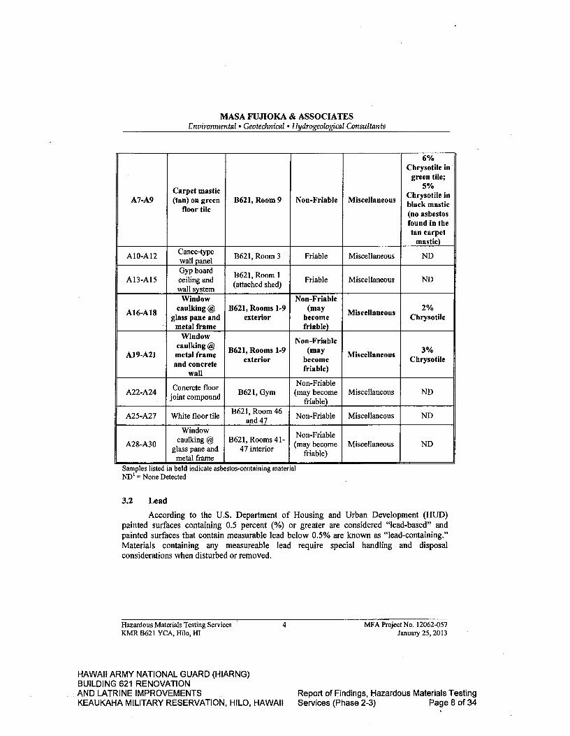
MASA FUJIOKA & ASSOCIATES Environmental • Geotechnical • Hydrogeological Consultants
A7-A9 Carpet mastic (tan) on green
floor tile B621, Room 9 Non-Friable Miscellaneous
6% Chrysotile in'
green tile; 5%
Chrysotile in black mastic (no asbestos found in the tan carpet
mastic)
Al0-Al2 Canec-type wall panel
B621, Room 3 Friable Miscellaneous ND
A13-A15 Gyp board ceiling and wall system
B621, Room! (attached shed)
Friable Miscellaneous ND
A16-A18
Window caulking @
glass pane and metal frame
B621, Rooms 1-9 exterior
Non-Friable (may
become friable)
Miscellaneous 2% Chrysotile
A19-A21
Window caulking ® metal frame and concrete
wall
B621, Rooms 1-9 exterior
Non-Friable (may
become friable)
Miscellaneous 3% Chrysotile
A22-A24 Concrete floor joint compound
B621, Gym Non-Friable (may become
friable) Miscellaneous ND
A25-A27 White floor tile B621, Room 46 and 47
Non-Friable Miscellaneous ND
A28-A30
Window caulking @
glass pane and metal frame
B621, Rooms 41- 47 interior
Non-Friable (may become
fir iable) Miscellaneous ND
Samples listed in bold indicate asbestos-containing material ND' = None Detected
3.2 Lead
According to the U.S. Department of Housing and Urban Development (HUD) painted surfaces containing 0.5 percent (%) or greater are considered "lead-based" and painted surfaces that contain measurable lead below 0.5% are known as "lead-containing." Materials containing any measureable lead require special handling and disposal considerations when disturbed or removed.
Hazardous Materials Testing Services
4 MFA Project No. 12062-057 KMR B621 YCA, Hilo, HI January 25, 2013
HAWAII ARMY NATIONAL GUARD (HIARNG) BUILDING 621 RENOVATION AND LATRINE IMPROVEMENTS
Report of Findings, Hazardous Materials Testing
KEAUKAHA MILITARY RESERVATION, HILO, HAWAII Services (Phase 2-3) Page 8 of 34
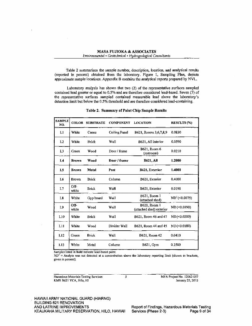
MASA FUJIOKA & ASSOCIATES Environmental • Geotechnical • Hydrogeological Consultants
Table 2 summarizes the sample number, description, location, and analytical results (reported in percent) obtained from the laboratory. Figure 1, Sampling Plan, depicts approximate sample locations. Appendix B contains the analytical reports prepared by NVL.
Laboratory analysis has shown that two (2) of the representative surfaces sampled contained lead greater or equal to 0.5% and are therefore considered lead-based. Seven (7) of the representative surfaces sampled contained measurable lead above the laboratory's detection limit but below the 0.5% threshold and are therefore considered lead-containing.
Table 2. Summary of Paint Chip Sample Results
SAMPLE COLOR SUBSTRATE COMPONENT LOCATION - RESULTS (%)
Li White Canec Ceiling Panel B621, Rooms 3,6,7,8,9 0.0830
L2 White Brick Wall B621, All interior 0.0590
L3 Green Wood Door frame B621 Room 6
(restroom) 0.0210
L4 Brown Wood Door I frame B6219 All 1.2000
L5 Brown Metal Post B621, Exterior 1.4000
L6 Brown Brick Column B621, Exterior 0.4000
L7 white Brick Wall B621 Exterior 0.0190
L8 White Gyp board Wall B621, Room I (attached shed) ND' (<0.0075)
L9 white Wood Wall B621, Room 1 (attached shed) exterior
ND (<0.0190)
L10 White Brick Wall B621, Room 46 and 47 ND (<0.0200)
L11 White Wood Divider Wall B621, Room 44 and 45 ND (<0.0180)
L12 Green Brick Wall B621, Room 42 0.0410
L13 White Metal Column B621, Gym 0.2500
Samples listed in bold indicate lead-based paint. ND' - Analyte was not detected at a concentration above the laboratory reporting limit (shown in brackets, given in percent).
Hazardous Materials Testing Services 5
MFA Project No. 12062-057 KMR B621 YCA, Hilo, HI
January 25, 2013
HAWAII ARMY NATIONAL GUARD (HIARNG) BUILDING 621 RENOVATION AND LATRINE IMPROVEMENTS
Report of Findings, Hazardous Materials Testing
KEAUKAHA MILITARY RESERVATION, HILO, HAWAII Services (Phase 2-3) Page 9 of 34

MASA FUJIOKA & ASSOCIATES Environmental . Geotechnical a Hydrogeological Consultants
3.3 Lighting
MFA observed various lighting systems throughout the spaces and representative lighting ballasts were examined. The 'newer' fixtures contained electronic ballasts and therefore do not contain PCBs. The 'older' fixtures contained the traditional (magnetic) ballast and the "No PCBs" labels were not found; therefore, certain lighting ballasts encountered must be assumed to contain polychlorinated biphenyls (PCBs). Associated lamps in all fixtures must be assumed to contain mercury.
3.4 Arsenic
Canec-type material obtained from ceiling and wall panels were submitted to NVL to identify total arsenic content. Appendix C contains the analytical report prepared by NVL. The laboratory has reported the total arsenic content as follows in the two samples:
• As - White ceiling panel, brown inner, B621, Rooms 3,6,7,8,9 (1800.0 mg/kg) • As2 - White wall panel, brown inner, B621, Room 3 separator wall (350.0
mg/kg)
Hazardous Materials Testing Services
6 MFA Project No. 12062-057 KMR B621 YCA, Hilo, HI January 25, 2013
HAWAII ARMY NATIONAL GUARD (HIARNG) BUILDING 621 RENOVATION AND LATRINE IMPROVEMENTS
Report of Findings, Hazardous Materials Testing
KEAUKAHA MILITARY RESERVATION, HILO, HAWAII Services (Phase 2-3) Page 10 of 34
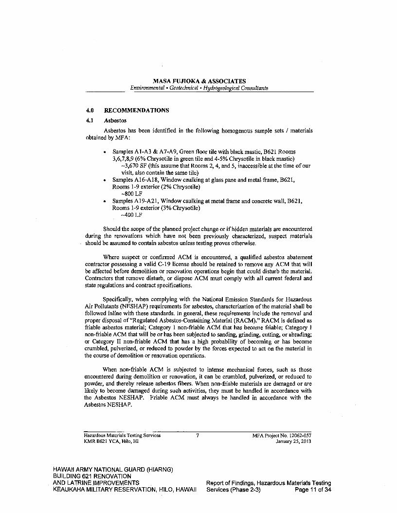
MASA FUJIOKA & ASSOCIATES Environmental • Geotechnical 'HydrOgeological Consultants
4.0 RECOMMENDATIONS
4.1 Asbestos
Asbestos has been identified in the following homogenous sample sets / materials obtained by MFA:
• Samples A1-A3 & A7-A9, Green floor tile with black mastic, B621 Rooms 3,6,7,8,9(6% Chrysotile in green tile and 4-5% Chrysotile in black mastic)
3,670 SF (this assume that Rooms 2, 4, and 5, inaccessible at the time of our visit, also contain the same tile)
• Samples A16-A18, Window caulking at glass pane and metal frame, B621, Rooms 1-9 exterior (2% Chrysotile)
8OO LF • Samples A19-A21, Window caulking at metal frame and concrete wall, B621,
Rooms 1-9 exterior (3% Chrysotile) 4OO LF
Should the scope of the planned project change or if hidden materials are encountered during the renovations which have not been previously characterized, suspect materials should be assumed to contain asbestos unless testing proves otherwise.
Where suspect or confirmed ACM is encountered, a qualified asbestos abatement contractor possessing a valid C-19 license should be retained to remove any ACM that will be affected before demolition or renovation operations begin that could disturb the material; Contractors that remove disturb, or dispose ACM must comply with all current federal and state regulations and contract specifications.
Specifically, when complying with the National Emission Standards for Hazardous Air Pollutants (NESHAP) requirements for asbestos, characterization of the material shall be followed inline with these standards. In general, these requirements include the removal and proper disposal of "Regulated Asbestos-Containing Material (RACM)." RACM is defined as friable asbestos material; Category I non-friable ACM that has become friable; Category I non-friable ACM that will be or has been subjected to sanding, grinding, cutting, or abrading; or Category II non-friable ACM that has a high probability of becoming or has become crumbled, pulverized, or reduced to powder by the forces expected to act on the material in the course of demolition or renovation operations.
When non-friable ACM is subjected to intense mechanical forces, such as those encountered during demolition or renovation, it can be crumbled, pulverized, or reduced to powder, and thereby release asbestos fibers. When non-friable materials are damaged or are likely to become damaged during such activities, they must be handled in accordance with the Asbestos NESHAP. Friable ACM must always be handled in accordance with the Asbestos NESHAP.
Hazardous Materials Testing Services 7 MFA Project No. 12062-057 KMR B621 YCA, fib, HI January 25, 2013
HAWAII ARMY NATIONAL GUARD (HIARNG) BUILDING 621 RENOVATION AND LATRiNE IMPROVEMENTS
Report of Findings,- Hazardous Materials Testing
KEAUKAHA MILITARY RESERVATION, HILO, HAWAII Services (Phase 2-3) Page 11 of 34

MASA FUJIOKA & ASSOCIATES Environmental' Geotechnical Hydrogeological Consultants
There are also notification requirements when certain quantities of RACM will be abated. These quantities include amounts greater than or equal to 160 square feet of RACM on facility components, 260 linear feet on pipes, or 35 cubic feet or more on facility components.
4.2 Lead
Lead-based surfaces/paints have been identified in MFA's survey in the following samples:
• Sample L4, Brown wood door / frame, B621, All (1.2000%) • Sample L5, Brown metal post, B621, Exterior (1.4000%)
Lead-containing surfaces/paints have been identified in MFA's survey in the following samples:
• Sample Li, White canec ceiling panel, B621, Rooms 3,6,7,8,9 (0.0830%) • Sample L2, White brick wall, B621, All interior (0.0590%) • Sample L3, Green wood door / frame, B621, Room 6 (restroom) (0.0210%) • Sample L6, Brown brick column, B621, Exterior (0.4000%) • Sample L7, Off-white brick wall, B621, Exterior (0.0 190%) • Sample L12, Green brick wall, B621, Room 42 (0.0410%) • Sample L13, White metal column, B621, Gym (0.2500%)
Although the lead content of any painted/coated surface can vary from area to area, those surfaces encountered by the Contractor that appear homogeneous with the surfaces described in Table 2 should be evaluated with discretion as they may contain comparable amounts of lead.
Should the scope of the renovations change or if hidden surfaces are encountered during the project, suspect materials that have not been tested should be assumed to contain measurable lead unless testing proves otherwise.
During all construction work where an employee may be occupationally exposed to lead or where lead-containing surfaces are expected to be disturbed or disposed, contractors must comply with all current federal and state regulations, and contract specifications. All work related to construction, including renovations, demolitions, painting and decorating, is included. Under current regulations, construction includes, but is not limited to:
) demolition or salvage of structures where lead or materials containing lead are present;
> removal or encapsulation of materials containing lead;
Hazardous Materials Testing Services
8 MFA Project No. 12062-057 KMR B621 YCA, Hilo, HI January 25, 2013
HAWAII ARMY NATIONAL GUARD (HIARNG) BUILDING 621 RENOVATION AND LATRINE IMPROVEMENTS
Report of Findings, Hazardous Materials Testing
KEAUKAHA MILITARY RESERVATION, HILO, HAWAII Services (Phase 2-3) Page 12 of 34

MASA FUJIOKA & ASSOCIATES Environmental • Geotechnical e Hydrogeological Consultants
> transportation, disposal, storage, or containment of lead or materials containing lead on the site or location at which construction activities are performed.
Additionally, a Toxicity Characteristic Leaching Procedure (TCLP) lead analysis may be required to characterize projected waste streams prior to disposal.
4.3 Lighting
Contractors should visually inspect all light fixtures to determine the proper disposal method. Ballasts manufactured since 1979 that do not contain PCBs are usually labeled with a sticker to that effect. Ballasts that do not have the sticker should be segregated and treated as if they do contain PCBs for proper disposal. If PCB ballasts have been punctured or are leaking, they must be handled and disposed of properly. Where ballasts are handled and/or disposed in any way, the Contractor must comply with all current federal and state regulations, and contract specifications, including the disposal requirements for fluorescent light ballasts from the TSCA when disposing of any lighting ballast.
Lamps in the lighting standards found in the buildings surveyed may fall under the category of "Universal Waste." Examples of common universal waste electric lamps include, but are not limited to, fluorescent, high intensity discharge, neon, mercury vapor, high pressure sodium, and metal halide lamps. The Contractor is responsible for characterizing which type of lamp will be demolished as part of the subject project.
Contractors must collect, properly handle, and dispose of universal waste in accordance with all current federal and state regulations, and contract specifications, including EPA 40 CFR 273, Standards for Universal Waste Management. The provisions found in EPA 40 CFR 260-268 may also apply.
4.4 Arsenic
Laboratory analysis of the canec panel samples are as follows:
• As - White ceiling panel, brown inner, B621, Rooms 3,6,7,8,9 (1800.0 mg/kg) • As2 - White wall panel, brown inner, B621, Room 3 separator wall (350.0
mg/kg)
Based on the laboratory results, the disturbance of these panels could result in an arsenic dust hazard.
Should the scope of the renovations change or if hidden materials are encountered during the project, suspect materials that have not been tested should be assumed to contain measurable arsenic unless testing proves otherwise.
Hazardous Materials Testing Services
9 MFA Project No. 12062-057 KMR B621 YCA, Hilo, HI January 25, 2013
HAWAII ARMY NATIONAL GUARD (HIARNG) BUILDING 621 RENOVATION AND LATRINE IMPROVEMENTS
Report of Findings, Hazardous Materials Testing
KEAUKAHA MILITARY RESERVATION, HILO, HAWAII Services (Phase 2-3) Page 13 of 34

MASA FUJIOKA & ASSOCIATES Environmental • Geotechnical & Hydrogeological Consultants
Where the Contractor encounters materials containing arsenic, the provisions, including but not limited to those, found in OSHA 29 CFR 1910.10181 29 CFR 1910 & 1926 Subpart Z, Toxic and Hazardous Substances and HIOSH 12-202 Health Standards, Toxic Materials and Harmful Physical Agents, shall be followed. These regulations apply to all construction work where an employee may be occupationally exposed to arsenic. Contractors who disturb arsenic-containing building materials must comply with all applicable federal and state regulations, and contract specifications to manage arsenic-containing materials in such a way that does not result in worker or public exposure of arsenic-contaminated dust or debris.
With respect to disposal of such materials, a regulatory exclusion for arsenically treated wood products exists under federal hazardous waste regulations, but the material should be disposed of appropriately and in accordance with any additional requirements a State-licensed landfill may impose.
5.0 LIMITATIONS
The findings presented in this report are professional opinions based solely upon visual observations of the site and the results of sampling and analysis. This report is intended exclusively for the purpose outlined herein and at the site location and project indicated. This investigation may not be appropriate to satisfy the needs of other users, and any use or re-use of this document or the findings, conclusions, or recommendations presented herein is at the sole risk of said user.
Masa Fujioka & Associates services are normally performed, within the limits prescribed by its clients, with the usual thoroughness and competence of the consulting profession, in accordance with the standard for professional services at the time those services are rendered. No warranty or representation, expressed or implied, is included or intended in its proposals, contracts, or reports. Opinions and recommendations presented herein apply to site conditions existing at the time of our investigation and those reasonably foreseeable; they cannot necessarily apply to site changes of which this office was not aware.
Additional ACM, LBP, or other types of hazardous materials could be present in areas not accessible or not shown to MFA at the time of our site visit.
Hazardous Materials Testing Services
10 MFA Project No. 12062-057 KMR B621 YCA, Hilo, HI January 25,2013
HAWAII ARMY NATIONAL GUARD (HIARNG) BUILDING 621 RENOVATION AND LATRINE IMPROVEMENTS
Report of Findings, Hazardous Materials Testing
KEAUKAHA MILITARY RESERVATION, H1LO, HAWAII Services (Phase 2-3) Page 14 of 34

0 C-,)
11
WA
Jo b
#:
La
LU
(0
r') C
LI) 0 0
Ir-
U) < -J <
0
Ir- U)
(0
-t
I
LI 'J Li
I Ii
LI)
0 C,)
Dat
e: J
anua
ry 2
013
HAWAII ARMY NATIONAL GUARD (HIARNG) BUILDING 621 RENOVATION AND LATRINE IMPROVEMENTS
Report of Findings, Hazardous Materials Testing
KEAUKAHA MILITARY RESERVATION, H1LO, HAWAII Services (Phase 2-3) Page 15 of 34
APPENDICES
HAWAII ARMY NATIONAL GUARD (HIARNG) BUILDING 621 RENOVATION AND LATRINE IMPROVEMENTS
Report of Findings, Hazardous Materials Testing
KEAUKAHA MILITARY RESERVATION, HILO, HAWAII Services (Phase 2-3) Page 16 of 34

APPENDIX A
Analytical Report - Asbestos
HAWAII ARMY NATIONAL GUARD (HIARNG) BUILDING 621 RENOVATION AND LATRINE IMPROVEMENTS
Report of Findings, Hazardous Materials Testing
KEAUKAHA MILITARY RESERVATION, HILO, HAWAII Services (Phase 2-3) Page 17 of 34
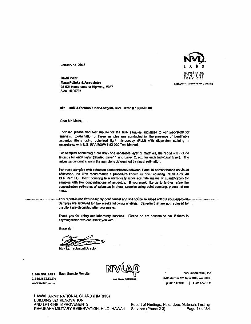
January 14, 2013 IN\M9. LABS
INDUSTRIAL HYGIENE
David Mater
SERVICES
Masa Fujioka & Associates Laboratory I Management Training 98-021 Kamehameha Highway, #337 Alea, HI 96701
RE: Bulk Asbestos Fiber Analysis, NVL Batch #1300509.00
Dear Mr. Maier,
Enclosed please find test results for the bulk samples submitted to our laboratory for analysis. Examination of these samples was conducted for the presence of Identifiable asbestos fibers using polarized light microscopy (PLM) with dispersion staining in accordance with U.S. EPA/6001M4-82-020 Test Method.
For samples containing more than one separable layer of materials, the report will Include findings for each layer (labeled Layer I and Layer 2, etc. for each individual layer). The asbestos concentration in the sample is determined by visual estimation.
For those samples with asbestos concentrations between I and 10 percent based on visual estimation, the EPA recommends a procedure known as point counting (NESHAPS, 40 CFR Part 61). Point counting is a statistically more accurate means of quantification for samples with low concentrations of asbestos. If you would like us to further refine the concentration estimates of asbestos in these samples using point counting, please let me know.
This report isconsidered.highly confidential and will not be released Wlthout•yourapproval Samples are archived for two weeks following analysis. Samples that are not retrieved by the client are discarded after two weeks.
Thank you for using our laboratory services. Please do not hesitate to call If there is anything further we can assist you with.
Sincerely,
Nick y, Technical Director
1.888.NVL.LA13S Enc.: Sample Results 1.888.(685.5227) www.nvllabs.com
NVL Laboratories, Inc. 4708 Aurora Ave N, Scathe, WA 98103
p206.547.0100 1 f 206.634.1936 Lob Cod.: 102063-0
HAWAII ARMY NATIONAL GUARD (HIARNG) BUILDING 621 RENOVATION AND LATRINE IMPROVEMENTS
Report of Findings, Hazardous Materials Testing
KEAUKAHA MILITARY RESERVATION, HILO, HAWAII Services (Phase 2-3) Page 18 of 34

Sampled by: Client
Analyzed by: Nadezhda Prysyazhnyuk Reviewed by: Nick Ly
Date:01/1412013 Date:01/14/2013 Nick ¶ nlcal Director
NVL Laboratories, Inc 4708 Aurora Ave. N., Seethe, WA 98103 Tel: 20 6.547.0100, Fax 206.634.1936
www.nvltabs.com Bulk Asbestos Fibers Analysis By Polarized Light Microscopy
For the scope of accreditation under NVLAP Lab Code 102063.0
1
Client: Mesa Fujioka & Associates
Batch #: 1300509.00 Address: 98-021 Kamehameha Highway, #337
Client Project #: 0621KMR B621 YCA
Also, HI 96701
Date Received: 01/1112013 Samples Received: 30
Attention: Mr. David Maler Samples Analyzed: 22
Project Location: Hilo Method: EPA/600R-93/1 16
Lab ID: 13003297 LocatIon: Hilo
Layer I of 2
Client Sample #: Al
Description: Green We
Layer 2 of 2
Non-Fibrous Materials:
Calcareous particles, Vinyl/Binder
Description: Black asphaltic mastic
Non-Fibrous Materials:
Asphalt/Binder, Mastic/Binder
Other Fibrous Materials:%
Asbestos Type: %
None Detected ND
Chrysotile 6%
Other Fibrous Materlals:% Asbestos Type: %
None Detected ND Chrysotiie 4%
Lab 10: 13003298 Client Sample #: A2
Sample Status: Not Analyzed
Lab ID: 13003299 Client Sample #: A3
Sample Status: Not Analyzed
Lab ID: 13003300 Client Sample #: A4 Location: Hilo L5Y5f1 Of -i D4 tiptIon B?dwn compressed fiI*ouiñiãtëilal Irâcepbnf
Non-Fibrous Materials: Other Fibrous Materlals:%
Fine particles, Adhesive/Binder, Paint Cellulose 97%
Asbestos Type: %
None Detected NO
Description: Brown compressed fibrous material with paint
Non-Fibrous Materials: Other Fibrous Materials:%
Fine particles, Adhesive/Binder, Paint Cellulose 95%
Lab ID: 13003301 Location: Hilo
Layer I of I
Client Sample #: A5
Asbestos Type: %
None Detected ND
Note: if samples are not homogeneous, then subsamples of the components were analyzed separately. All bulk samples are analyzed using EPA 600/M4 -82-020 Method with the following measurement unoertaintles for the reported % Asbestos (1%-0-3%, 5%"1-9%, 10%--5-15%,20%=10-30%,50%=40 -60%). This report relates only to the Items tested. If sample was not collected by NVL personnel, then the accuracy of the results Is limited by the methodology and acuity of the sample collector. This report shall not be reproduced except in full, without written approval of NVL Laboratories, Inc. It shall not be used to claim product endorsement by NVLAP or any other agency of the US Government.
Page 1 d7
HAWAII ARMY NATIONAL GUARD (HIARNG) BUILDING 621 RENOVATION AND LATRINE IMPROVEMENTS
Report of Findings, Hazardous Materials Testing
KEAUKAHA MILITARY RESERVATION, HILO, HAWAII Services (Phase 2-3) Page 19 of 34

Sampled by: Client
Analyzed by: Nadezhda Prysyazhnyuk Date:01/14/2013 Reviewed by: Nick Ly Date: 01/14/2013
p
NVL Laboratories, Inc
14.
4708 Aurora Ave. N., Seattle, WA 98103 For the scope of accreditation under NVLAP Lab Code 102063-0 Tel: 206.547.0100, Fax: 206.634.1936
www.nvliabs.com ulk Asbestos Fibers Analysis By Polarized Light Microscopy
Client: Masa Fujloka & Associates
Batch #: 130050900 Address: 98-021 Kamehameha Highway, #337
Client Project #; 062/KMR 8621 YCA
Alea, HI 96701
Date Received: 01/11/2013 Samples Received: 30
Attention: Mr. David Mater
Samples Analyzed: 22 Project Location: Hilo
Method: EPA/600R-93/1 16
Lab ID: 13003302 Client Sample #: A6 Location: Hilo
Layer I of I Description: Brown compressed fibrous material with paint
Non-Fibrous Materials: Other Fibrous Materiais:%
Fine particles, Adhesive/Binder, Paint Cellulose 96%
Asbestos Type: ¼
None Detected NO
Lab ID: 13003303 Client Sample #: A7 Location: Hilo Layer I of 3 Description: Yellow and trace white soft mastic
Non-Fibrous Materials: Other Fibrous Materiais:% Asbestos Type: %
Calcareous particles, Mastic/Binder Synthetic fibers <1% None Detected NO
Layer 2 of 3 Description: Green tile
Non-Fibrous Materials: Other Fibrous Materials:% Asbestos Type: ¼
Calcareous particles, Vinyl/Binder None Detected ND Chrysotlle 6%
Layer 3 of 3 DescriptIon: Black asphaltic mastic
Non-Fibrous Materials:
Other Fibrous Materlats:%
Asbestos Type: ¼
Asphalt/Binder, Mastic/Binder
Cellulose 1%
Chrysotile 5%
Lab ID: 13003304
Client Sample #: A8
Sample Status: Not Analyzed
Lab ID: 13003305 Client Sample #: A9
Sample Status: Not Analyzed
Lab ID: 13003306 Client Sample #: AlO Location: Hilo
Note: If samples are not homogeneous, then subsamples of the components were analyzed separately. All bulk samples are analyzed using EPA 600/M4 -82-020 Method with the followIng measurement uncertalnttes for the reported % Asbestos (1%=0.3%, 5%=1-9%, 10%=5-15%, 20%=10-30%, 50%=40 -80%). This report relates only to the Items tested. If sample was not collected by NVL personnel, then the accuracy of the results Is limited by the methodology and acuity of the sample collector. This report shell not be reproduced except in full, without wrItten approval of NVL Laboratories, Inc. It shall not be used to daim product endorsement by NVLAP or any other agency of the US Government.
Page 2ofl
HAWAII ARMY NATIONAL GUARD (HIARNG) BUILDING 621 RENOVATION AND LATRINE IMPROVEMENTS
Report of Findings, Hazardous Materials Testing
KEAUKAHA MILITARY RESERVATION, HILO, HAWAII Services (Phase 2-3) Page 20 of 34
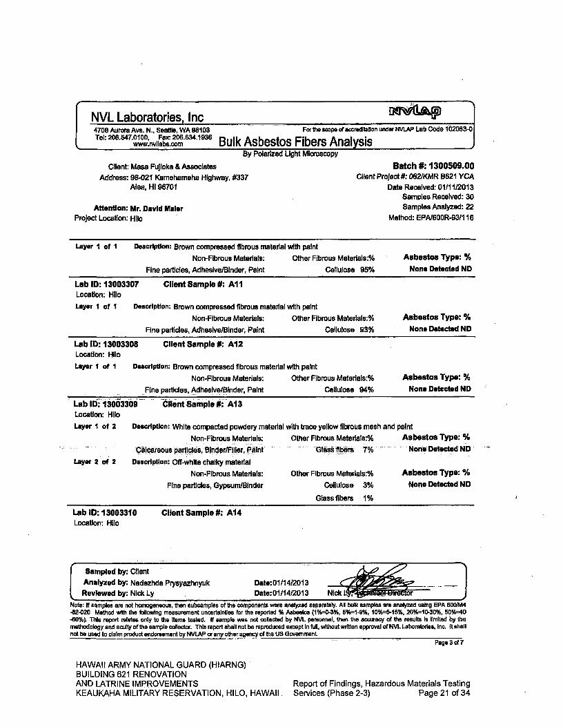
NVL Laboratories, Inc 4708 Aurora Ave. N., Seattle, WA 08103 For to scope of accreditation under NVLAP Lab Code 102063-0 Tel: 206.547.0100, Fax: 206.634.1936
www.nvliabs.com Bulk Asbestos Fibers Analysis
I.
By Polarized Light Microscopy
Client: Mesa FuJloka & Associates Batch #: 1300509.00
Address: 98-021 Kamehameha Highway, #337
Client Project #: 082/KMR 8621 YCA Ale 8-v Hi 96701
Date Received: 01/11/2013 Samies Received: 30
Attention: Mr. David Maler Samples Analyzed: 22
Project Location: Hilo Method: EPN600R-9311 16
Layer I of I
Description: Brown compressed fibrous material with paint
Non-Fibrous Materials: Other Fibrous Materials:%
Asbestos Type: %
Fine particles, Adhesive/Binder, Paint Cellulose 95%
None Detected NO
Lab ID: 13003307 Client Sample #: All Location: Hilo
Layer I of I Description: Brown compressed fibrous material with paint
Non-Fibrous Materials: Other Fibrous Materiais:%
Fine particles, Adhesive/Binder, Paint Cellulose 93%
Asbestos Type: %
None Detected NO
Lab ID: 13003308 Client Sample #: Al2 Location: Hilo
Layer I of I Description: Brown compressed fibrous material with paint
Non-Fibrous Materials: Other Fibrous Materiais:%
Fine particles, Adhesive/Binder, Paint Cellulose 94%
Asbestos Type: % None Detected ND
Lab ID: 13003309 Client Sample #: A13 Location: Hilo
Layer I of 2 Description: White compacted powdery material with trace yellow fibrous mesh and paint
Non-Fibrous Materials:
Other Fibrous Materlais:%
Asbestos Type: °c
Calcarsous particles Binder/Filler ---- Paint Glass fibers 7% None Detected ND "'
Layer 2 of 2
Description: Off-white chalky material
Non-Fibrous Materials:
Other Fibrous Materlals:%
Asbestos Type: %
Fine particles, Gypsum/Binder
Cellulose 3%
None Detected NO
Glass fibers 1%
Lab ID: 13003310 Client Sample #: A14 Location: Hilo
Sampled by: Client
Analyzed by: Nadezhda Prysyazhnyuk Date:01/1412013
¼ RevIewed by; Nick Ly Date:0111412013 Nick L - .r 00
Note: If samples are not homogeneous, then subsamples of the components were analyzed separately. All bulk samples are analyzed using EPA 600110114 -82-020 Method with the following measurement uncertainties for the reported % Asbestos (1%0-3%, 50/6=1-90/6, 10%5-15%, 20%10-30% 50%40 -60%). This report relates only to the Items tested. If sample was not collected by NVL personnel, then the accuracy of the results is limited by the methodology and acuity of the sample collector. This report shall not be reproduced except In full, without written approval of NVL Laboratories, Inc. It shall not be used to claim product endorsement by NVLAP or any other agency of the us Government
Page 3 of 7
HAWAII ARMY NATIONAL GUARD (HIARNG) BUILDING 621 RENOVATION AND LATRINE IMPROVEMENTS
Report of Findings, Hazardous Materials Testing
KEAUKAHA MILITARY RESERVATION, HILO, HAWAII Services (Phase 2-3) Page 21 of 34

Sample Status: Not Analyzed Lab ID: 13003313 Client Sample #: All
Not Analyzed Sample Status: Lab ID: 13003314 Client Sample #: A18
Lab ID: 13003312 Client Sample #: A16
Description: Light gray putty material with paint
Non-Fibrous Materials: Other Flbrout.Materials:%
cä!careous pàrtldes, Binder/Filler, Paint Hone Detected NO
Location: Hilo
Layer I of I
Asbestos Type: % . . ....... Chrysotlle 2%
Sampled by: Client
Analyzed by: Nadezhda Prysyaztinyuk Date:01/14/2013 Reviewed by: Nick Ly Date:01114/2013 Nick L
,11W
_ -, (rJJ
NVL Laboratories, Inc 4708 Aurora Ave. N., Seattle, WA 98103 For the scope of accreditation under NVLAP Lab Code 102083-0 Tel: 206.547.0100, Fax: 206.634.1936
www.nvllabs.com Bulk Asbestos Fibers Analysis By Polarize4 Light Microscopy
/
Client: Mesa Fujioka & Associates
Batch #: 1300509.00 Address: 98-021 Kamehameha Highway, #337
Client Project #: 062/KMR B621 YCA
Ala, HI 96701
Date Received: 01/1112013 Samples Received: 30
Attention: Mr. David Maler Samples Analyzed: 22
Project Location: Hilo
Method: EPN600R-93/1 16
Layer I of I Description: Off-white chalky material with paper and paint
Non-Fibrous Materials:
Fine particles, Gypsum/Binder, Paint
Other Fibrous Materiais:%
Cellulose 18%
Glass fibers 1%
Asbestos Type: %
None Detected ND
Lab ID: 13003311 Client Sample #: A15 Location: Hue
Layer I of 2 Description: White soft material with paint
Non-Fibrous Materials:
Calcareous particles, Binder/Filler, Paint
Other Fibrous Materiats:%
Asbestos Type: %
None Detected ND
None Detected ND
Layer 2 of 2 DescrIption: Off-white chalky material with paper and paint
Non-Fibrous Materials: Other Fibrous Materlals:%
Asbestos Type: %
Fine particles, Gypsum/Binder, Paint
Cellulose 16%
None Detected ND
Glass fibers 2%
Note: If samples are not homogeneous, then subsamples of the components were analyzed separately. Al bulk samples are analyzed using EPA 600/M4 -82-020 Method with the following measurement uncertainties for the reported % Asbestos (1%=0-3%, 5%=1-9%, 10%-5-15%, 20%10.30%, 50%40 .80%). ThIs report relates only to the items tested. if sample was not collected by NVL personnel, then the accuracy of the results is limited by the methodology and acuity of the sample collector. This report shall not be reproduced except in full, without written approval of NVL Laboratories, Inc. It shall not be used to claim product endorsement by NVLAP or any other agency of the US Government.
Page of
HAWAII ARMY NATIONAL GUARD (HIARNG) BUILDING 621 RENOVATION AND LATRINE IMPROVEMENTS KEAUKAHA MILITARY RESERVATION, HILO, HAWAII
Report of Findings, Hazardous Materials Testing Services (Phase 2-3) Page 22 of 34
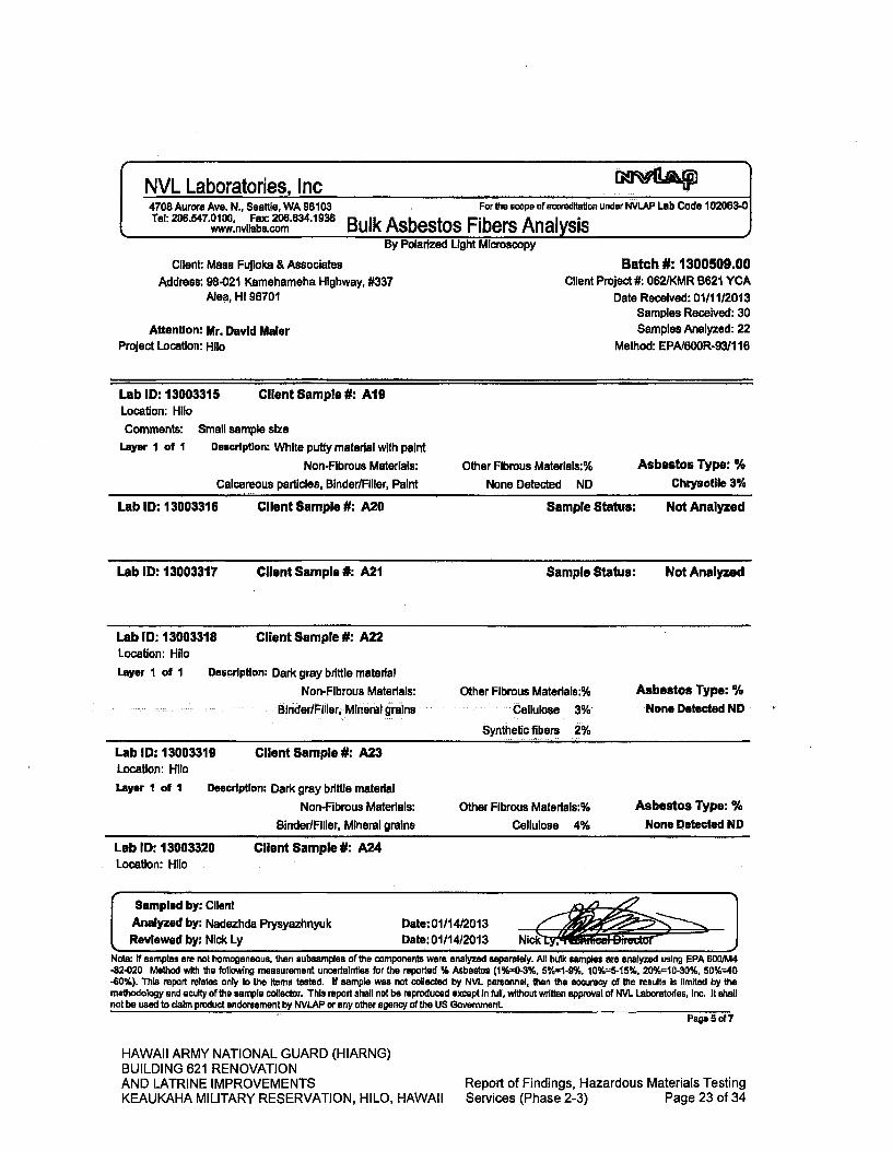
Client Sample #: A22
Description: Dark gray brittle material
Non-Fibrous Materials:
Binder/Flller Mineral grains
Other Fibrous Materials:%
Cellulose 3%
Synthetic fibers 2%
Asbestos Type: %
None Detected ND
Lab ID: 13003318 Location: Hilo Layer I of I
Client Sample #: A23
Description: Dark gray brittle material
Non-Fibrous Materials:
Binder/Filler, Mineral grains
Other Fibrous Materials:% Asbestos Type: %
Cellulose 4% None Detected ND
Lab ID: 13003319 Location: Hilo
Layer I of I
p
NVL Laboratories, Inc 4708 Aurora Ave. N., Seattle, WA 98103 For the scope of accreditation under NVLAP Lab Code 102063-0 Tel: 206.547.0100, Fax: 206.634.1936
www.nvllabs corn Bulk Asbestos- Fibers Analysis I
By Polarized Light Microscopy
Client: Mass Fujioka & Associates
Batch #: 1300509.00 Address: 98-021 Kamehameha Highway, #337
Client Project #: 062/KMR B621 YCA
Aloe, HI 96701
Date Received: 01/11/2013 Samples Received: 30
Attention: Mr. David Mater Samples Analyzed: 22
Project Location: Hilo
Method: EPA/600R-9311 16
Lab ID: 13003315 Client Sample #: A19 Location: Hilo
Comments: Small sample size Layer I of I Description: White putty material with paint
Non-Fibrous Materials: Calcareous particles. Binder/Filler, Paint
Other Fibrous Materlals:%
None Detected ND
Asbestos Type: % Chrysotile 3%
Lab ID: 13003316 Client Sample #: A20
Sample Status: Not Analyzed
Lab ID: 13003317 Client Sample #: A21
Sample Status: Not Analyzed
Lab ID: 13003320 Client Sample #: A24 Location: Hilo
Sampled by: Client .. g
Analyzed by: Nadezhda Prysyazhnyuk Date:01/14/2013 A I I ~r; 1V - P Reviewed by: Nick Ly Date: 01/14/2013 Nick
Note: If samples are not homogeneous, then subsamples of the components were analyzed separately. All bulk samples are analyzed using EPA 6001M4 -82-020 Method with the following measurement uncertainties for the reported % Asbestos (1%0-3%, 5%1-9%, 10%"5-15%, 20%10-30%, 50%-40 -60%). This report relates only to the Items tested. If sample was not collected by NVL personnel, then the accuracy of the results Is limited by the methodology and acuity of the sample collector. ThIs report shall not be reproduced except in full, without written approval of NVL Laboratories, Inc. It shall not be used to claim product endorsement by NVLAP or any other agency of the US Government
Page 5of7
HAWAII ARMY NATIONAL GUARD (HIARNG) BUILDING 621 RENOVATION AND LATRINE IMPROVEMENTS
Report of Findings, Hazardous Materials Testing
KEAUKAHA MILITARY RESERVATION, HILO, HAWAII Services (Phase 2-3) Page 23 of 34
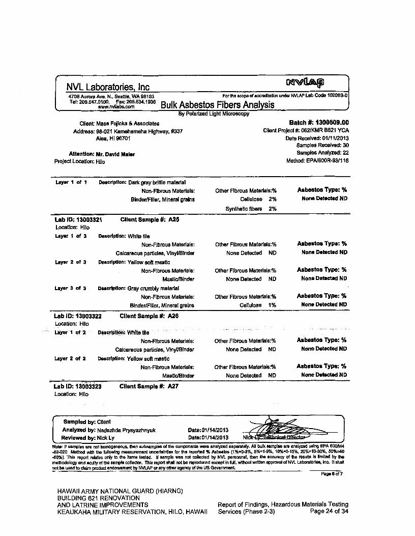
Sampled by: Client
Analyzed by: Nadezhda Piysyazhnyuk Date:01/14/2013 _______ Reviewed by: Nick Ly Date: 01/14/2013 rqlcwmL
Lab ID: 13003322 Location: Hilo
Layer 1 of 2
Client Sample #: A26
Dèicrlptlófl: Whit e tile--- -
Non-Fibrous Materials:
Other Fibrous Materlais:%
Calcareous particles, Vinyl/Binder
None Detected ND
Description: Yellow soft mastic
Non-Fibrous Materials: Other Fibrous Materials:%
Mastic/Binder None Detected ND
Asbestos Type: %
None Detected ND
Asbestos Type: %
None Detected NO
Layer 2 of 2
Lab ID: 13003323
Client Sample #: A27 Location: Hilo
NVL Laboratories Inc 1".
4708 Aurora Ave. N., Seattle, WA 98103 For the scope of ared1tstlon uriderNVLAP Lab Code 102083.0 Tel: 206.547.0100, Fax: 206.634.1936 Bulk Asbestos Fibers Analysis
By Polarized Light Microscopy
Client: Mass Fujioka & Associates Batch #: 1300509.00
Address: 98-021 Kamehameha Highway, #337
Client Project #: 062/KMR B621 YCA Aba, HI 96701
Date Received: 01/11/2013 Samples Received: 30
Attention: Mr. David Maier Samples Analyzed: 22
Project Location: Hilo Method: EPN600R-93/1 16
Layer I of I
Description: Dark gray brittle material
Non-Fibrous Materials:
Other Fibrous Materlals:%
Asbestos Type: %
Binder/Filler, Mineral grains
Cellulose 2%
None Detected NO
Synthetic fibers 2%
Other Fibrous Matertals:% Asbestos Type: %
None Detected ND None Detected ND
Other Fibrous Materiais:% Asbestos Type: %
None Detected ND None Detected ND
Other Fibrous Materials:%
Asbestos Type: %
Cellulose 1%
None Detected NO
Lab ID: 13003321
Client Sample #: A25 Location: Hilo
Layer I of 3
Description: White tile
Non-Fibrous Materials:
Calcareous particles, Vinyl/Binder
Layer 2 of 3
Description: Yellow soft mastic
Non-Fibrous Materials:
Mastic/Binder
Layer 3 of 3
Description: Gray crumbly material
Non-Fibrous Materials:
Binder/Filler, Mineral grains
Note: If samples are not homogeneous, then subsamples of the components were analyzed separately. All bulk samples are analyzed using EPA 6001M4 -82-020 Method with the following measurement uncertainties for the reported % Asbestos (1%=0-3%, 5%1-9% 10%5-15% 20%10-30%, 50%=40 -60%). ThIs report relates only to the Items tested. If sample was not collected by I'NL personnel, then the accuracy of the results Is limited by the methodology and acuity of the sample collector. This report shell not be reproduced except in full, without written approval of NVL Laboratories, Inc. It shall not be used to claim product endorsement by NVLAP or any other agency of the US Government. -
Page 6 of 7
HAWAII ARMY NATIONAL GUARD (HIARNG) BUILDING 621 RENOVATION AND LATRINE IMPROVEMENTS
Report of Findings, Hazardous Materials Testing
KEAUKAHA MILITARY RESERVATION, HILO, HAWAII Services (Phase 2-3) Page 24 of 34
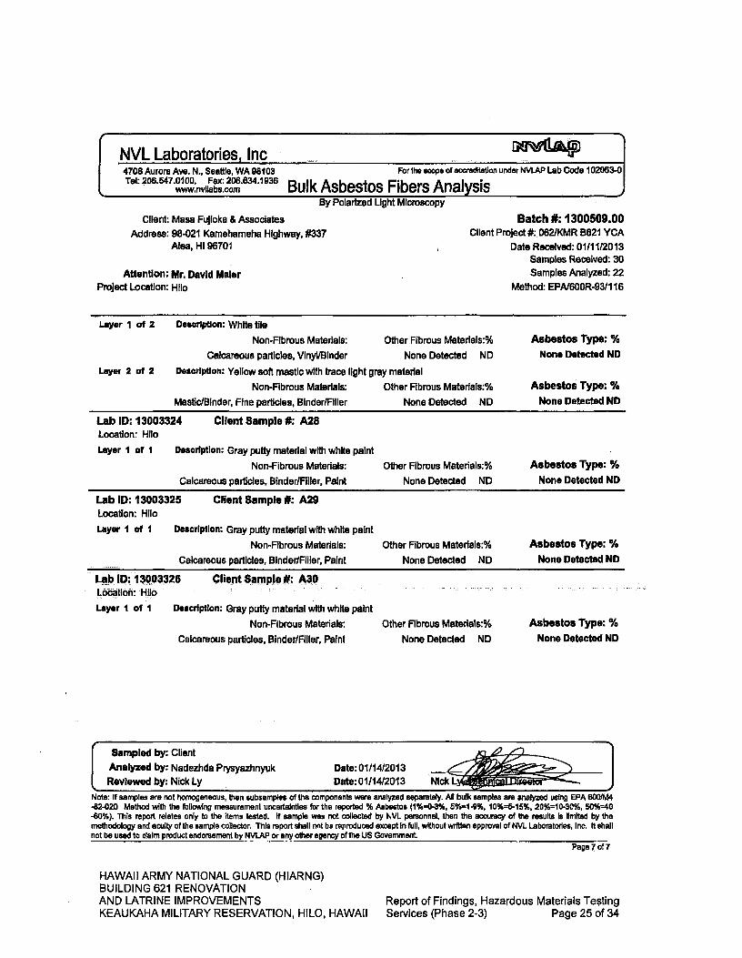
Lab ID: 13003324 Location: Hilo
Layer I of I
Client Sample #: A28
Description; Gray putty material with white paint
Lab ID: 13003325 Location: Hue
Layer I of I
Client Sample #: A29
Description: Gray putty material with white paint
Sampled by: Client
Analyzed by: Nadezhda Prysyazhnyuk Reviewed by: Nick Ly
Date: 01/14/2013 Date: 01/1412013
NVL Laboratories, Inc 4708 Aurora Ave. N., Seattle, WA 98103 For the scope of accreditation under NVLAP Lab Code 102063-0 Tel: 206.547.0100, Fax: 206.634.1936
www.nvllabs.com Bulk Asbestos Fibers Analysis ) By Polarized Light Microscopy
Client: Masa Fujioka & Associates Batch #: 1300509.00
Address: 98-021 Kamehameha Highway, #337
Client Project #: 062IKMR B621 YCA Ala, Hi 96701
Date Received: 0111112013 Samples Received: 30
Attention: Mr. David Maler Samples Analyzed: 22
Project Location: Hilo
Method: EPN600R-93/1 16
Layer I of 2
Layer 2 of 2
Description: White tile
Non-Fibrous Materials: Other Fibrous Materiais:% Asbestos Type: %
Calcareous particles, Vinyl/Binder None Detected ND None Detected NO
Description: Yellow soft mastic with trace light gray material
Non-Fibrous Materials: Other Fibrous Materlais:% Asbestos Type: %
Mastic/Binder, Fine particles, Binder/Filler
None Detected ND None Detected NO
Non-Fibrous Materials: Other Fibrous Materials:%
Asbestos Type: %
Calcareous particles, Binder/Filler, Paint None Detected ND
None Detected ND
Non-Fibrous Materials: Other Fibrous Materials:%
Asbestos Type: %
Calcareous particles, Binder/Filler, Paint
None Detected ND
None Detected ND
Description: Gray putty material with white paint
Non-Fibrous Materials: Other Fibrous Matedals:%
Calcareous particles, Binder/Filler, Paint None Detected ND
Lab ID: 13003326 Location: HlIó
Layer I of I
Client Sample #: 11 A30
Asbestos Type: %
None Detected ND
Note: If samples are not homogeneous, then subsamples of the components were analyzed separately. All bulk samples are analyzed using EPA 600/M4 -82-020 Method with the following measurement uncertainties for the reported % Asbestos (1%0-3%, 50/61-9%, 10%=5-15%, 20%10-30%, 50%40 -60%). This report relates only to the items tested. if sample was not collected by NVL personnel, then the accuracy of the results Is limited by the methodology and acuity of the sample collector. This report shall not be reproduced except in full, without written approval of NVL Laboratories, Inc. It shell not be used to claim product endorsement by NVLAP or any other agency of the US Government.
Page 7 oIl
HAWAII ARMY NATIONAL GUARD (HIARNG) BUILDING 621 RENOVATION AND LATRINE IMPROVEMENTS
Report of Findings, Hazardous Materials Testing
KEAUKAHA MILITARY RESERVATION, H1LO, HAWAII Services (Phase 2-3) Page 25 of 34
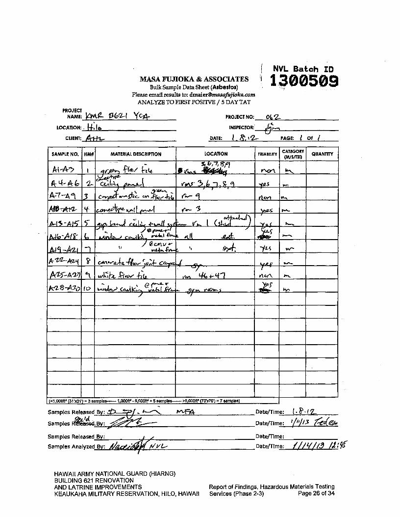
PROJECT NO: Ot,'Z PRNAME OJECT
Y-K9- I3é( YC*
OF / 6---n
DATE: PAGE:
Date/Time: Samples Released By:
Date/Time: 41//.3 /2:91 Samples Analyzed By: Aze-4rj
HAWAII ARMY NATIONAL GUARD (HIARNG) BUILDING 621 RENOVATION AND LATRINE IMPROVEMENTS KEAUKAHA MILITARY RESERVATION, HILO, HAWAII
Report of Findings, Hazardous Materials Testing Services (Phase 2-3) Page 26 of 34
INSPECTOR: LOCATION:.
MASA FLJJIOKA & ASSOCIATES Bulk Sample Data Sheet (Asbestos)
Please email results to: [email protected] ANALYZE TO FIRST POSITVE /5 DAY TAT
SAMPLE NO. HM# MATERIAL DESCRIPTION LOCATION - FRIABILITY CATEGORY QUANTITY
MM> "2..- A 4 A ci2i.h 51b () 711 ,
A--7 -A 1 3 op"ho " '1 AM 'f 4a )90-15
c ...c.. I 1
NG -At , iuo csL r ' ç
AA-' -
AS5--A" cl C-Iqw 4- kr1 a" '-
224.7 to raw 4'
(<1 000ft (31 x31) = 3 samples..-- I 000ft2 5 000ft2 5 samples-- >5 000R (70x7O) 7 samples)
F4 Date/Time:
Date/Time: Samples Released By:
Samples Ftesed.By: 1/liJ/3 1~e* ~~
NVL Batch.
.2~ -awn-ft~ W
CLIENT:

APPENDIX B
Analytical Report - Lead
HAWAII ARMY NATIONAL GUARD (HIARNG) BUILDING 621 RENOVATION AND LATRINE IMPROVEMENTS
Report of Findings, Hazardous Materials Testing
KEAUKAHA MILITARY RESERVATION, HILO, HAWAII Services (Phase 2-3) Page 27 of 34
Nick Ly, Technical Director
1.888.NVLLABS 1.888(685,5227) www.nvllabs.com
Enclosure:
January 15, 2013
David Maier Maca Fujioka & Associates 98-021 Kamehameha Highway, #337 Aba, HI 96701
IN DUSTRiM. H V G I :E..PJ.E S E. R V C E $
Lsbortory Manernent I Tra1nn
RE: Metals Analysis; NVL Batch # 1300507.00
Dear Mr. Maber,
Enclosed please find the test results for samples submitted to our laboratory for analysis. Preparation of these samples was conducted following protocol outlined in EPA Method SW 846-3051 unless stated otherwise. Analysis of these samples was performed using analytical instruments in accordance with U.S. EPA, NIOSH, OSHA and other ASTM methods.
For matrix materials submitted as paint, dust wipe, soil or TCLP samples, analysis for the presence of total metals is conducted using published U.S. EPA Methods. Paint and soil results are usually expressed in mg/Kg which Is equivalent to parts per million (ppm). Lead (Pb) in paint Is usually expressed In mg/Kg (ppm) , Percent (%) or mg/cm2 by area, Dust wipe sample results are usually expressed in ug/wipe and ug/ft2. TCLP samples are reported in mg/L (ppm). For air filter samples, analyses are conducted using NIOSH and OSHA Methods. Results are expressed in ug/fllter and ug/m3. Other matrix materials are analyzed accordingly using published methods or specified by client. The reported test results pertain only to items tested. Lead test results are not blank corrected.
For recent regulation updates pertaining to current regulatory levels or permissible exposure levels, please call your local regulatory agencies for more details.
This report isconsideredhighiy confidential and .will not be released without yourapprovaL Samples are archived for two Weeks following analysis. Samples that are not retrieved by the client are discarded after two weeks.
Thank you for using our laboratory services, if you need further assistance please feel free to call us at 206-547-0100 or 1-888-N VLLABS,
Sincerely,
NVL Laboratories, Inc. 4708 Aurora Ave N, Seattle, WA 98103
p 206,547.0100 f 206.634.1936
HAWAII ARMY NATIONAL GUARD (HIARNG) BUILDING 621 RENOVATION AND LATRINE IMPROVEMENTS
Report of Findings, Hazardous Materials Testing
KEAUKAHA MILITARY RESERVATION, HILO, HAWAII Services (Phase 2-3) Page 28 of 34

NVL Laboratories, IncAAt"
4708 Aurora Ave. N., Seattle, WA 98103 AIHA -IH# 101861 Tel: 206.547.0100, Fax: 206.634.1936
www.nvllabs.com Analysis Report WA - DOE # C1765 JD1ID
LASORATORY
Total Lead (Pb)
Client: Mass Fujioka & Associates Address: 98-021 Karnehameha Highway, #337
Alea, HI 96701
Attention: Mr. David Maier Project Location: Hilo
Batch #: 1300507.00 Matrix: Paint Chips
Method: EPA 7000B Client Project #: 062/KMR B621 YCA
Date Received: 01/1112013 Samples Received: 13 Samples Analyied: 13
Sample RL In Results Results In Lab ID
Client Sample # Weight (g) mglKg In mglkg percent
13003282 LI 0.2004
49.0 830.0 0.0830
13003283 12 0.0356
140.0 590.0 0.0590
13003284
13003285
13003286
L3 0.1956 50.0 210.0 0.0210
14 0.1138 87.0 12000.0 1.2000
L5 0.1021 97.0 14000.0 1.4000
13003287 16 0.0875
110.0 4000.0 0.4000
13003288 L7 0.1041
95.0 190.0 0.0190
13003289 L8 0.1308
75.0 <75.0 <0.0075
13003290 19 0.0529
190.0 <190.0 <0.0190
13003291 110 0.0502
200.0 <200.0 <0.0200
yo, ø9Z LII 00549 1800 <1800 <00180
13003293 112 0.0480
100.0 410.0 0.0410
13003294 L13 0.0521
190.0 2500.0 0.2500
Sampled by: Client Analyzed by: Jacob Blair
Reviewed by: Nick Ly Date Analyzed: 01/15/2013
Date issued: 01/15/2013 ctor
-i
mg/ Kg =Milligrams per kilogram RL = Reporting Limit Percent = Milligrams per kilogram / 10000 '<' = Below the reporting Limit Note: Method QC results are acceptable unless stated otherwise.
Unless otherwise Indicated, the condition of all samples was acceptable at time of receipt. Bench Run No: 33-0111-06
Page 1 of I
HAWAII ARMY NATIONAL GUARD (HIARNG) BUILDING 621 RENOVATION AND LATRINE IMPROVEMENTS Report of Findings, Hazardous Materials Testing KEAUKAHA MILITARY RESERVATION, HILO, HAWAII Services (Phase 2-3) Page 29 of 34
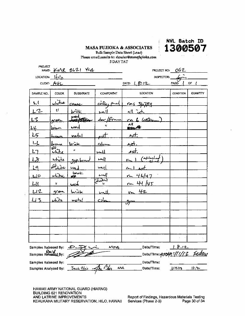
CUNT: &WLI-
NVL Batch ID
130,0507 MASA FUJIOKA & ASSOCIATES Bulk Sample Data Sheet (Lead)
Please email results to: [email protected] 5 DAY TAT
PROJECT NO: O2_ INSPECTOR:
PROJECT
NAME: J!!~A Kj2-i 'y'c4
LOCATION:
DATE: ( - OF PAGE:
Report of Findings, Hazardous Materials Testing Services (Phase 2-3) Page 30 of 34
HAWAII ARMY NATIONAL GUARD (HIARNG) BUILDING 621 RENOVATION AND LATRINE IMPROVEMENTS KEAUKAHA MILITARY RESERVATION, HILO, HAWAII
SAMPLE NO. COLOR SUBSTRATE COMPONENT LOCATION CONDITION QUANTflY
C c )
/1 hrt4. i(
LLE
LL, co
Lj
L L%J(#-41z
)704aJ 1
Lot A wmv(
LIC) 7AC#
v -t'fL4 7 Lit V r L4L( 1&ts-
Ll CDIU L)y
6L. AJUL 5JIt.Ja (ut
Samples Released By: 4
Samples ieaeBy:
Samples Released By:
Samples Analyzed By:
Date/Time: I. IP2_.
Date/11me:O4flfØ lvav Date/Time:
Date/Time: /1/I3 I1I'

APPENDIX C
Analytical Report - Arsenic
HAWAII ARMY NATIONAL GUARD (HIARNG) BUILDING 621 RENOVATION AND LATRINE IMPROVEMENTS Report of Findings, Hazardous Materials Testing KEAUKAHA MILITARY RESERVATION, HILO, HAWAII Services (Phase 2-3) Page 31 of 34

Nick Ly, Technical Director
3.888.NVLLARS L-88846 -52-7) www.nvHabcorn
Enclosure:
Januarvl5,2013
L A B $
David Maier Masa Fujioka & Associates 98-021 Kamehameha Highway, #337 Aiea, HI 96701
I N D U S TR I A L HYGIENE SERVICES
rap ipmem:
RE: Metals Analysis; NVL Batch # 1300508.00
Dear Mr. Maler,
Enclosed please find the test results for samples submitted to our laboratory for analysis. Preparation of these samples was conducted following protocol outlined In EPA Method SW 846-3051 unless stated otherwise. Analysis of these samples was performed using analytical instruments in accordance with U.S. EPA, NIOSH, OSHA and other ASTM methods.
For matrix materials submitted as paint, dust wipe, soil or TCLP samples, analysis for the presence of total metals is conducted using published U.S. EPA Methods. Paint and soil results are usually expressed in mg/Kg which Is equivalent to parts per million (ppm). Lead (Pb) In paint Is usually expressed In mg/Kg (ppm), Percent (%) or mg/cm2 by area. Dust wipe sample results are usually expressed in ug/wipe and uglft2. TCLP samples are reported in mg/L (ppm). For air filter samples, analyses are conducted using NIOSH and OSHA Methods. Results are expressed In ug/fllter and ugim3. Other matrix materials are analyzed accordingly using published methods or specified by client. The reported test results pertain only to items tested. Lead test results are not blank corrected.
For recent regulation updates pertaining to current regulatory levels or permissible exposure levels, please call your local regulatory agencies for more details.
It pQrtAcgnstderect Samples are archived for two weeks following analysis. Samples that are not retrieved by the client are discarded after two weeks.
Thank you for using our laboratory services. if you need further assistance please feel free to call us at 206-547-0100 or 1-888-N VLLABS.
Sincerely,
WVL LaboratOries, Inc.
4708 Aurora Ave N, Seattle, WA 98103
p 206.547.0100 f 206.634.1936
HAWAII ARMY NATIONAL GUARD (HIARNG) BUILDING 621 RENOVATION AND LATRINE IMPROVEMENTS
Report of Findings, Hazardous Materials Testing
KEAUKAHA MILITARY RESERVATION, HILO, HAWAII Services (Phase 2-3) Page 32 of 34

NVL Laboratories. Inc. 4708 Aurora Ave. N.. Seattle WA 98103 Tel: 206547.0100, Fax: 206.634.1936
www.nvllabs.com ANA -JH#101861
Analysis Report
RL = Reporting Limit = Below the reporting Limit
mg/ kg = Milligrams per kilogram ppm = Parts per million Note: Method QC results are acceptable unless stated otherwise.
Unless otherwise indicated, the condition of all samples was acceptable at time of receipt. Bench Run No: 33-0114-05
Report of Findings, Hazardous Materials Testing Services (Phase 2-3) Page 33 of 34
HAWAII ARMY NATIONAL GUARD (H1ARNG) BUILDING 621 RENOVATION AND LATRINE IMPROVEMENTS KEAUKAHA MILITARY RESERVATION, HILO, HAWAII
Total Metals Client: Masa Fujioka & Associates
Address: 98-021 Kamehameha Highway. #337 Alea, HI 96701
Attention: Mr. David Mater Project Location: Hilo
Batch #: 1300508.00 Matrix: Paint Chls Method: EPA 6010
Client Project #: 062/KMR B621 YCA Date Received: 01/1 1/2013
Samples Received: 2 Samples Analyzed: 2
Sample RL Results In Results In Lab ID Client Sample # Elements wt (g) mg 1kg mg kg ppm
13003295 AM Arsenic (As) 0.0404 50.0 1800.0 1800.0
13003296 A82
Arsenic (As) 0.0430 47.0 350.0 350.0
Page 1 of I
Sampled by: Client Analyzed by: Jacob Blair
Reviewed by: Nick Lv
AA 100
Date Analyzed: 01/15/2013 Date Issued: 01/15/2013 '' '" al Director
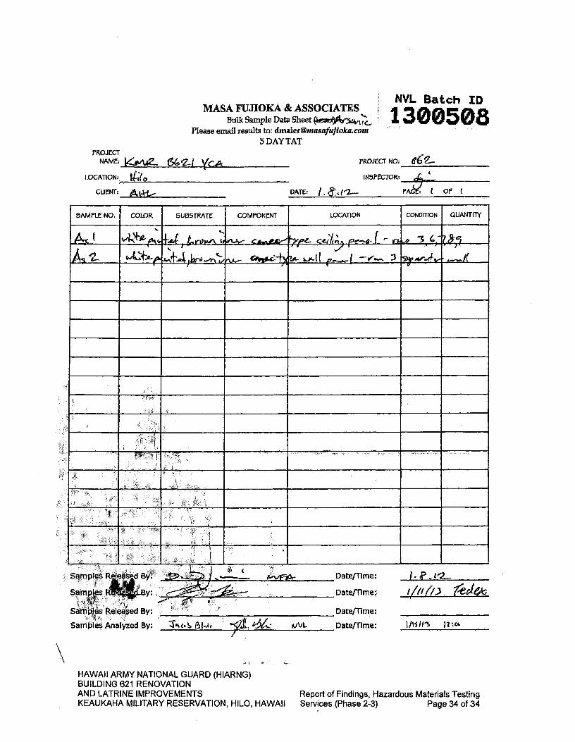
MASA FUJIOKA & ASSOCIATES Bulk Sample Data Sheet
Please email results to: [email protected] 5 DAY TAT
NVL Batch ID
1300508
PROJECT NAME: 661I YCA
PROJECT NO: iff C42,
LOCATION:
IN5PECTOR:
CUNT:
DATE: I,
SAMPLE NO. COLOR 5LJ5TA1T COMPONENT LOCATION CONDITION QUANTITY
IM-AA," fxp C1Iv; '—a I r 3 lw;2ff~l
+4) 4v
mpies Releas- d B"' y: ...L... Date/Time:
Samples Date/Time: t/fU'..3 2cI6 0 4
Samples Peleaed By Date/Time
Samples Analyzed By: t Ø, kI r./'Jt Date/Time: 1Ii11 12
HAWAII ARMY NATIONAL GUARD (HIARNG) BUILDING 621 RENOVATION AND LATRINE IMPROVEMENTS
Report of Findings, Hazardous Materials Testing
KEAUKAHA MILITARY RESERVATION, HILO, HAWAII Services (Phase 2-3) Page 34 of 34
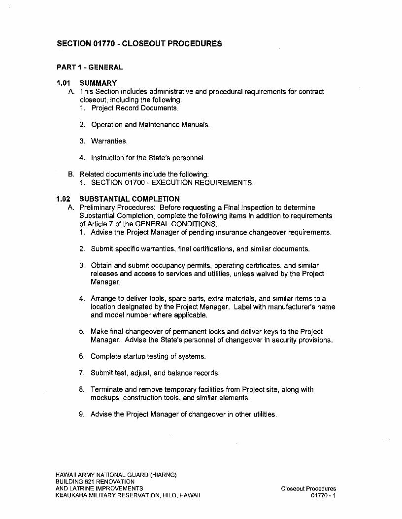
SECTION 01770 - CLOSEOUT PROCEDURES
PART I -GENERAL
1.01 SUMMARY A. This Section includes administrative and procedural requirements for contract
closeout, including the following: 1. Project Record Documents.
2. Operation and Maintenance Manuals.
3. Warranties.
4. Instruction for the State's personnel.
B. Related documents include the following: 1. SECTION 01700- EXECUTION REQUIREMENTS.
1.02 SUBSTANTIAL COMPLETION A. Preliminary Procedures: Before requesting a Final Inspection to determine
Substantial Completion, complete the following items in addition to requirements of Article 7 of the GENERAL CONDITIONS. 1. Advise the Project Manager of pending insurance changeover requirements.
2. Submit specific warranties, final certifications, and similar documents.
3. Obtain and submit occupancy permits, operating certificates, and similar releases and access to services and utilities, unless waived by the Project Manager.
4. Arrange to deliver tools, spare parts, extra materials, and similar items to a location designated by the Project Manager. Label with manufacturer's name and model number where applicable.
5. Make final changeover of permanent locks and deliver keys to the Project Manager. Advise the State's personnel of changeover in security provisions.
6. Complete startup testing of systems.
7. Submit test, adjust, and balance records.
8. Terminate and remove temporary facilities from Project site, along with mockups, construction tools, and similar elements.
9. Advise the Project Manager of changeover in other utilities.
HAWAII ARMY NATIONAL GUARD (HIARNG) BUILDING 621 RENOVATION AND LATRINE IMPROVEMENTS
Closeout Procedures
KEAUKAHA MILITARY RESERVATION, HILO, HAWAII
01770-1
10. Submit changeover information related to the State's occupancy, use, operation, and maintenance.
11. Complete final cleaning requirements, including touch up painting.
12. Touch up and otherwise repair and restore marred exposed finishes to eliminate visual defects.
13. Submit the O&M Manual(s) for review.
14. Coordinate/provide documentation for Hawaii Energy Rebate submission by the State.
1.03 FINAL COMPLETION A. Preliminary Procedures: Within 10 days from the Project Acceptance Date,
complete the following items in addition to requirements of GENERAL CONDITIONS Article 7 PROSECUTION AND PROGRESS: 1. Instruct the State's personnel in operation, adjustment, and maintenance of
products, equipment, and systems. Submit demonstration and training media materials.
1.04 LIST OF INCOMPLETE ITEMS (PUNCH LIST) A. Preparation: Submit 2 copies of any updated and action taken list. In addition to
requirements of GENERAL CONDITIONS Article 7 PROSECUTION AND PROGRESS, include name and identification of each space and area affected by construction operations for incomplete items and items needing correction including, if necessary, areas disturbed by Contractor that are outside the limits of construction. 1. Organize list of spaces in sequential order, starting with exterior areas first
and proceeding from lowest floor to highest floor.
2. Organize items applying to each space by major element, including categories for ceiling, individual walls, floors, equipment, and building systems.
3. Include the following information at the top of each page: a. Project Name and Title.
b. State Job No.
c. Date and page number.
d. Name of Contractor.
1.05 PROJECT RECORD DOCUMENTS AND REQUIREMENTS A. General:
1. Definition: "Project Record Documents", including Record Drawings, shall fulfill the requirements of "Field-Posted As-Built Drawings" listed in the GENERAL CONDITIONS.
HAWAII ARMY NATIONAL GUARD (HIARNG) BUILDING 621 RENOVATION AND LATRINE IMPROVEMENTS
Closeout Procedures
KEAUKAHA MILITARY RESERVATION, HILO, HAWAII
01770-2
2. Do not use Project Record Documents for daily construction purposes. Protect Project Record Documents from deterioration and loss. Provide access to Project Record Documents for Project Manager's reference during normal working hours. Maintain these documents as specified in paragraph entitled "Record Drawings" hereinafter.
3. The Designer, under contract with the State, will update the drawings to show all addendum, PCD, and sketch changes. The Project Manager will transmit these drawings (vellum) to the Contractor who will make all "red-line" corrections to these drawings to record the changes depicted on the Contractor's Field Posted Record ("As-Builts") by accepted drafting practices as approved by the Project Manager.
4. Where the recorded changes depicted on the Contractor's Field Posted Record ("As-Builts") are in the form of shop drawings, the Contractor shall provide those shop drawings on vellum sheets in the same material and size as the drawings transmitted to the Contractor. The new drawing sheets shall be titled and numbered to conform to the construction drawings and clearly indicate what information they supercede in the actual construction drawings. For example a new drawing that replaces drawing M-3, could be numbered M3a.
5. The Contractor shall bring to the attention of the Project Manager any discrepancy between the changes made by the Designer and those depicted on addendum, PCD, and sketch changes. The Project Manager will resolve any conflicts.
6. Submit final Record Documents (Field Posted Record Drawings) within 10 days after the Final Inspection Date but no later than the Contract Completion Date, unless the GENERAL CONDITIONS require an earlier submittal date.
7. The Contractor shall guarantee the accuracy of its final Record Documents. The State will hold the Contractor liable for costs the State incurs as a result of inaccuracies in the Contractor's Record Documents.
8. Prepare and submit construction photographs and electronic files, damage or settlement surveys, property surveys, and similar final record information as required by the Project Manager.
9. Deliver tools, spare parts, extra materials, and similar items to a location designated by the Project Manager. Label with manufacturer's name and model number where applicable.
10. Submit pest-control final inspection report and warranty.
11. Submit Final, corrected O&M Manual(s).
HAWAII ARMY NATIONAL GUARD (HIARNG) BUILDING 621 RENOVATION AND LATRINE IMPROVEMENTS
Closeout Procedures
KEAUKAHA MILITARY RESERVATION, HILO, HAWAII
01770-3
B. Record Drawings: 1. Maintain a duplicate full-size set of Field Posted Record ("As-Builts")
Drawings at the job site. Clearly and accurately record all deviations from alignments, elevations and dimensions, which are stipulated on the drawings and for changes directed by the Project Manager that deviate from the drawings.
2. Record changes immediately after they are constructed in place and where applicable, refer to the authorizing document (Field Order, Change Order, or Contract Modification). Use red pencil to record changes. Make Field Posted Record Drawings available to the Project Manager at any time so that its clarity and accuracy can be monitored. a. Give particular attention to information on concealed elements that cannot
be readily identified and recorded later.
b. Accurately record information in an understandable drawing technique.
c. Record data as soon as possible after obtaining it. Record and check the markup before enclosing concealed installations.
d. Mark the contract drawings or the shop drawings, whichever is most capable of showing actual physical conditions, completely and accurately. Where Shop Drawings are marked, show cross-reference on contract drawings.
e. Mark important additional information that was either shown schematically or omitted from original Drawings.
f. Locate concealed building utilities by dimension from bench marks or permanent structures. Locate site utilities by dimensions, azimuth and lengths from bench marks or permanent structures.
g. Note field order numbers, Change Order numbers, Contract Modification numbers, Alternate numbers, post-construction drawing numbers (PCD) and similar identification (RFI numbers) where applicable.
h. The Contractor shall initial each deviation and each revision marking.
3. Use the final updated Contract Drawing set plus applicable shop drawings for making the final Field Posted Record Drawings submittal.
4. Certify drawing accuracy and completeness. Label and sign the record drawings.
HAWAII ARMY NATIONAL GUARD (HIARNG) BUILDING 621 RENOVATION AND LATRINE IMPROVEMENTS
Closeout Procedures
KEAUKAHA MILITARY RESERVATION, HILO, HAWAII
01770-4

5. Label the title sheet and on all sheets in the margin space to the right of the sheet number, written from the bottom upward, with the title "FIELD POSTED RECORD DRAWINGS" and certification information as shown below. Provide a signature line and company name line for each subcontractor that will also certify the respective drawing. Adjust size to fit margin space.
FIELD POSTED Certified By: Date: RECORD DRAWINGS [Contractor's Company Name]
6. Revise the Drawing Index and label the set "FIELD POSTED RECORD DRAWINGS". Include the label "A COMPLETE SET CONTAINS [ 1 SHEETS" in the margin at the bottom right corner of each sheet. Quantify the total number of sheets comprising the set.
7. If the Project Manager determines a drawing does not accurately record a deviation or omits relevant information, the State will correct any FIELD POSTED RECORD DRAWINGS sheet. Contractor will be charged for the State's cost to correct the error or omission.
8. Use the final Field Posted Record Drawings sheets to create one electronic version of the set. The set shall be recorded in Adobe Acrobat PDF (Portable Document Format). Create a single indexed, bookmarked PDF file of the entire set of drawings and record on the CD. Submit one set of the final Field Posted Record Drawings sheets and the complete electronic CD set(s).
1.06 WARRANTIES A. Submittal Time: Submit written manufacturer's warranties at request of the
Project Manager for designated portions of the Work where commencement of warranties other than Project Acceptance date is indicated.
B. Partial Occupancy: Submit properly executed manufacturer's warranties within 45 days of completion of designated portions of the Work that are completed and occupied or used by the State during construction period by separate agreement with Contractor.
C. Organize manufacturer's warranty documents into an orderly sequence based on the table of contents of the Specifications. 1. Bind warranties and bonds in heavy-duty, 3-ring, vinyl-covered, loose-leaf
binders, thickness as necessary to accommodate contents, and sized to receive 8-1/2 inch x 11-inch paper.
2. Provide heavy paper dividers with plastic-covered tabs for each separate warranty. Mark tab to identify the product or installation. Provide a typed description of the product or installation, including the name of the product and the name, address, and telephone number of Installer and prime contractor.
3. Identify each binder on the front and spine with the typed or printed title "WARRANTIES", Project Name and Title, State Job Number, and name of Contractor.
HAWAII ARMY NATIONAL GUARD (HIARNG) BUILDING 621 RENOVATION AND LATRINE IMPROVEMENTS
Closeout Procedures
KEAUKAHA MILITARY RESERVATION, HILO, HAWAII
01770-5

4. Use the final submittal of the warranties to create an electronic Adobe Acrobat PDF (Portable Document Format) version of the bound warranty documents files. Each sheet shall be separately scanned, at 600 DPI or better into a PDF file, indexed and recorded on a recordable compact disc (CD).
D. Provide 2 sets of manufacturer's warranties that exceed one year and one CD as part of the closing document submittals. Provide additional copies of each warranty to include in operation and maintenance manuals.
1.07 OPERATION AND MAINTENANCE MANUALS A. Assemble complete sets of operation and maintenance data indicating the
operation and maintenance of each system, subsystem, and piece of equipment not part of a system. Include operation and maintenance data required in individual Specification Sections and as follows: 1. Operation Data:
a. Emergency instructions and procedures.
b. System, subsystem, and equipment descriptions, including operating standards.
c. Operating procedures, including startup, shutdown, seasonal, and weekend operations.
d. Description of controls and sequence of operations.
e. Piping diagrams.
2. Maintenance Data: a. Manufacturer's information, Material Safety Data Sheets, and a list of
spare parts.
b. Name, address, and telephone number of installer or supplier.
c. Maintenance procedures.
d. Maintenance and service schedules for preventive and routine maintenance.
e. Maintenance record forms.
f. Sources of spare parts and maintenance materials.
g. Copies of maintenance service agreements.
h. Copies of warranties and bonds.
HAWAII ARMY NATIONAL GUARD (HIARNG) BUILDING 621 RENOVATION AND LATRINE IMPROVEMENTS
Closeout Procedures
KEAUKAHA MILITARY RESERVATION, HILO, HAWAII
01770-6
B. Use the following 3 paragraph headings, "Notes, Cautions and Warnings", to emphasize important and critical instructions and procedures. Place the words "Notes", "Cautions", or "Warnings" immediately before the applicable instructions or procedures. Notes, Cautions and Warnings are defined as follows: 1. Note: highlights an essential operating or maintenance procedure,
condition or statement.
2. Caution: highlights an operating or maintenance procedure, practice, condition or statement which if not strictly observed, could result in damage to or destruction of equipment, loss of designed effectiveness, or health hazards to personnel.
3. Warning: highlights an operating or maintenance procedure, practice, condition, or statement that if not strictly observed, could result in injury to or death of personnel.
C. Organize the Operation and Maintenance Manuals into suitable sets of manageable size. Bind and index data in heavy-duty, "D" type 3-ring, vinyl-covered, loose-leaf binders, in thickness necessary to accommodate contents, with pocket inside the covers to receive folded oversized sheets. Binder color shall be maroon, or if not available red. Identify each binder on front and spine with the printed title "OPERATION AND MAINTENANCE MANUAL", Project Name and Title include building number when appropriate, State Job Number, Prepared For: Youth Challenge Academy, Prepared By: Contractor and Volume Number. Each binder is a single volume.
D. Electronic Format 1. Provide all information (narratives, drawings and manual) on a Compact Disc
(CD). Provide drawings and plans prepared for the O&M Manuals drawn electronically and saved as a PDF file. Name and index the files for ease of identification and updates.
2. Provide the complete O&M Manual using Adobe Acrobat PDF (Portable Document Format) files. Each sheet shall be separately scanned into a PDF file, indexed, bookmarked, hyperlinked to the table of contents and recorded on a compact disc (CD). Scanned documents shall be scanned at 600 DPI or better. Indexes and bookmarks may be highlighted or colored text. The final submittal shall include written instructions for installing, accessing and retrieving information from the compact disc.
E. Pre-Final Submittal: Submit 2 printed sets of Pre-Final Operation and Maintenance Manuals, for review by the Project Manager, at least 5 days prior to scheduled final inspection. Manuals shall be marked as Pre-Final. Make any correction noted before submitting the final Operation and Maintenance Manuals. 1. The user and the Department will each keep one copy of the Pre-Final
submittal to operate and maintain the facility from the Project Acceptance Date through submission of the final submittal. Therefore, the submittal shall contain all the required information that is available at the time of submission.
HAWAII ARMY NATIONAL GUARD (HIARNG) BUILDING 621 RENOVATION AND LATRINE IMPROVEMENTS
Closeout Procedures
KEAUKAHA MILITARY RESERVATION, HILO, HAWAII
01770-7

2. One set will be returned with comments. Additional review comments may include problems discovered during the O&M Manual's review, site validation, and facility start up and will be provided to the Contractor after facility Project Acceptance Date.
F. Final Submittal: Use the final submittal of the manuals to create the electronic PDF file version of the bound Operation and Maintenance Manuals documents. Include the Submittal (100 percent) review comments along with a response to each item. Provide 6 Final sets of the printed manuals and 6 Final compact discs, (CDs) as part of the closing document submittal. Final printed manual and disks shall be marked as Final.
PART 2- PRODUCTS
2.01 MATERIALS A. Cleaning Agents: Use cleaning materials and agents recommended by
manufacturer or fabricator of the surface to be cleaned. Do not use cleaning agents that are potentially hazardous to health or property or that might damage finished surfaces.
PART 3- EXECUTION
3.01 DEMONSTRATION AND TRAINING A. Instruction: Instruct the State's personnel to adjust, operate, and maintain
systems, subsystems, and equipment not part of a system. 1. Provide instructors experienced in operation and maintenance procedures.
2. Provide instruction at mutually accepted times.
3. Schedule training with the State's users, through the Project Manager with at least 7 days advanced notice.
4. Coordinate instructors, including providing notification of dates, times, length of instruction, and course content.
B. Program Structure: Develop an instruction program that includes individual training modules for each system and equipment not part of a system, as required by individual Specification Sections. For each training module, develop a learning objective and teaching outline. Include instruction for the following: 1. System design and operational philosophy.
2. Review of documentation.
3. Operations.
4. Adjustments.
5. Troubleshooting.
HAWAII ARMY NATIONAL GUARD (HIARNG) BUILDING 621 RENOVATION AND LATRINE IMPROVEMENTS KEAUKAHA MILITARY RESERVATION, HILO, HAWAII
Closeout Procedures 01770-8
6. Maintenance.
7. Repair.
3.02 FINAL CLEANING A. General: Provide final cleaning. In addition to requirements of Article 7 of the
GENERAL CONDITIONS conduct cleaning and waste-removal operations to comply with local laws and ordinances and federal and local environmental and antipollution regulations.
B. Cleaning: Employ experienced workers or professional cleaners for final cleaning. Clean each surface or unit to condition expected in an average commercial building cleaning and maintenance program. Comply with manufacturers written instructions unless noted otherwise. Complete the following cleaning operations before requesting final inspection for entire Project or for a portion of Project: 1. Clean Project site, yard, and grounds, in areas disturbed by construction
activities, including landscape development areas, of rubbish, waste material, litter, and other foreign substances.
2. Sweep paved areas broom clean. Remove petrochemical spills, stains, and other foreign deposits resulting from construction activities.
3. Rake grounds that are neither planted nor paved to a smooth, even-textured surface.
4. Remove tools, construction equipment, machinery, and surplus material from Project site.
5. Clean exposed exterior and interior hard-surfaced finishes to a dirt-free condition, free of stains, films, and similar foreign substances. Avoid disturbing natural weathering of exterior surfaces. Restore reflective surfaces to their original condition.
6. Remove debris and surface dust from limited access spaces, including: roofs, plenums, shafts, trenches, equipment vaults, manholes, attics, and similar spaces.
7. Sweep concrete floors broom clean in unoccupied spaces.
8. Vacuum carpet and similar soft surfaces, removing debris and excess nap; shampoo if visible soil or stains remain.
9. Clean transparent materials, including mirrors and glass in doors and windows. Remove glazing compounds and other noticeable, vision-obscuring materials. Replace chipped or broken glass and other damaged transparent materials. Polish mirrors and glass surfaces, taking care not to scratch surfaces.
10. Remove labels that are not permanent.
HAWAII ARMY NATIONAL GUARD (HIARNG) BUILDING 621 RENOVATION AND LATRINE IMPROVEMENTS
Closeout Procedures
KEAUKAHA MILITARY RESERVATION, HILO, HAWAII
01770-9
II. Touch up and otherwise repair and restore marred, exposed finishes and surfaces. Replace finishes and surfaces that cannot be satisfactorily repaired or restored or that already show evidence of repair or restoration. a. Do not paint over "UL" and similar labels, including mechanical and
electrical nameplates.
12. Wipe surfaces of mechanical and electrical equipment and similar equipment. Remove excess lubrication, paint and mortar droppings, and other foreign substances.
13. Replace parts subject to unusual operating conditions.
14. Clean plumbing fixtures to a sanitary condition, free of stains, including stains resulting from water exposure.
15. Replace disposable air filters and clean permanent air filters. Clean the exposed surfaces of diffusers, registers, and grills.
16. Clean ducts, blowers, and coils if units were operated without filters during construction.
17. Clean light fixtures, lamps, globes, and reflectors to function with full efficiency. Replace burned-out bulbs, and those noticeably dimmed by hours of use, and defective and noisy starters in fluorescent and mercury vapor fixtures to comply with requirements for new fixtures.
18. Leave Project clean and ready for occupancy.
C. Pest Control: Engage an experienced, licensed exterminator to make a final inspection and rid Project of rodents, insects, and other pests. Prepare a report.
D. Comply with safety standards for cleaning. Do not burn waste materials. Do not bury debris or excess materials on the State's property. Do not discharge volatile, harmful, or dangerous materials into drainage and sewer systems or onto State property. Remove waste materials from Project site and dispose of lawfully.
END OF SECTION
HAWAII ARMY NATIONAL GUARD (HIARNG) BUILDING 621 RENOVATION AND LATRINE IMPROVEMENTS
Closeout Procedures
KEAUKAHA MILITARY RESERVATION, HILO, HAWAII
01770-10

DIVISION 2- SITE CONSTRUCTION
SECTION 02070 - SELECTIVE DEMOLITION
PART I - GENERAL
1.01 SUMMARY A. Extent of selective demolition work is indicated on drawings. Selective
demolition work includes, but is not limited to, removal and subsequent disposal of all non-hazardous materials indicated or required to be removed.
B. It shall be the responsibility of the Contractor to examine the project site and determine the existing conditions.
C. Execute all work in an orderly and careful manner with due consideration for all items of work to remain.
D. Obvious conditions which exist at the site shall be accepted as part of the work, even though they may not be clearly indicated on the Drawings and/or described herein, or may vary therefrom.
E. All debris of any kind accumulated from the work of this section shall be disposed off the site.
F. Burning of any debris on-site will not be permitted.
G. Permits, Notice, Etc.: 1. The Contractor shall procure and pay for all necessary permits, certificates,
or approvals that may be required in connection with this work.
2. The Contractor shall serve proper notice and consult with the Project Manager regarding any temporary barricades and disconnections of electrical or other utility lines in the area which may interfere with the removal work, and all such lines where necessary shall be properly disconnected or relocated before commencing with the work.
H. Carefully remove and store materials indicated for relocation or reinstallation. Record all deficiencies prior to removal and record with the Project Manager. All damage caused by the Contractor's operations shall be repaired as accepted by the Project Manager at no additional cost to the State.
I. Related Work Described Elsewhere: Contractor shall review SECTION 01715 - EXISTING CONDITIONS - ASBESTOS/LEAD/HAZARDOUS MATERIAL SURVEY.
1.02 SUBMITTALS A. Submit in accordance with SECTION 01330 - SUBMITTAL PROCEDURES.
HAWAII ARMY NATIONAL GUARD (HIARNG) BUILDING 621 RENOVATION AND LATRINE IMPROVEMENTS
Selective Demolition
KEAUKAHA MILITARY RESERVATION, HILO, HAWAII
02070-1
B. Schedule: Submit two copies of schedule indicating proposed methods and sequence of operations for selective demolition work to the Project Manager for review prior to commencement of work. Include coordination for temporary shut-off and continuation of utility services as required, together with details for weather protection, dust and noise control protection.
C. Permits and Notices: Submit a State Department of Health, Asbestos Notification of Demolition & Renovation form (a facsimile is attached).
1.03 JOB CONDITIONS A. Condition of Structure: The State assumes no responsibility for actual condition
of items or portions of structure to be demolished.
B. Conditions existing at time of commencement of contract will be maintained by the State insofar as practicable.
C. Do not interfere with use of adjacent occupied spaces or buildings. Maintain free and safe passage to and from occupied spaces or other occupied buildings.
D. Partial Demolition and Removal: Items indicated to be removed but of salvageable value to Contractor, may be removed as work progresses. Transport salvaged items from site as they are removed. Storage or sale of removed items on site will not be permitted.
E. Protections: Provide temporary barricades and other forms of protection as required to protect the general public and staff from injury due to selective demolition work. 1. Provide interior and exterior shoring, bracing, or support to prevent
movement, settlement, or collapse of structure or elements to be demolished, and adjacent facilities or work to remain.
2. Protect from damage existing finish work that is to remain in place and becomes exposed during demolition operations.
3. Life safety procedures and provisions shall be in conformance with all applicable Federal, State, and County regulations, including HIOSH.
4. Provide accessibility around temporary structures conforming to ADAAG Section 201.3 and Section 206.1.
5. Remove protections, obstructions, and barricades at completion of work.
6. Where barriers are erected or placed to facilitate the work, barriers shall not affect or impact the facility's fire exiting route or alarm systems.
F. Damages: Promptly repair damages caused to adjacent facilities by demolition work at no cost to the State.
HAWAII ARMY NATIONAL GUARD (HIARNG) BUILDING 621 RENOVATION AND LATRINE IMPROVEMENTS
Selective Demolition
KEAUKAHA MILITARY RESERVATION, HILO, HAWAII
02070-2

G. Traffic: Conduct selective demolition operations and debris removal in a manner to ensure minimum interference with roads, streets, walks, and other adjacent occupied or used facilities. Do not close, block or otherwise obstruct streets, walks or other occupied or used facilities without written permission from the Project Manager. Provide alternate routes around closed or obstructed traffic ways if required by governing regulations, as directed by the Project Manager.
H. Dust Control: 1. Keep dust within acceptable levels at all times, including non-working hours,
weekends, and holidays, as specified in SECTION 01500 - TEMPORARY FACILITIES AND CONTROLS.
2. Only wet grinding or cutting of concrete will be allowed on exterior surfaces.
3. Mechanical dry sweeping not permitted. Vacuuming, wet mopping, approved limited dry hand, wet or damp sweeping is acceptable.
4. During loading operations, water down debris and waste materials to allay dust.
5. The method of dust control and all costs incurred thereof shall be the responsibility of the Contractor.
6. Enclosed chutes shall be used for removing debris from above the ground floor level.
7. All carpet to be removed shall be vacuumed with a commercial vacuum prior to removal to remove dust particles.
I. Noise Control: As specified in SECTION 01500 - TEMPORARY FACILITIES AND CONTROLS.
J. Fire Safety: Fire safety during demolition shall comply with NFPA 241, "Standard for Safeguarding Construction, Alteration, and Demolition Operations", and NFPA 1, "Uniform Fire Code", as amended.
K. Demolition Work: Conform to State of Hawaii, Occupational Safety and Health Standards; Subtitle 8, Division of Occupational Safety and Health; Part 3, Construction Standards; Chapter 131.1, Demolition.
L. Other Controls: 1. Wherever trucks and/or vehicles leave the site and enter surrounding paved
streets, the Contractor shall prevent any material from being spilled onto the pavement. Waste water shall not be discharged into existing streams, waterways, or drainage systems such as gutter and catch basins unless treated to comply with Department of Health pollution regulations.
2. Trucks hauling materials shall be covered as required by PUC regulation. Trucks hauling fine materials shall be covered.
HAWAII ARMY NATIONAL GUARD (HIARNG) BUILDING 621 RENOVATION AND LATRINE IMPROVEMENTS
Selective Demolition
KEAUKAHA MILITARY RESERVATION, HILO, HAWAII
02070-3

PART 2- PRODUCTS
(Not Applicable)
PART 3- EXECUTION
3.01 INSPECTION A. Prior to commencement of selective demolition work, inspect areas in which
work will be performed. Inventory existing conditions of structure surfaces, equipment or surrounding properties which could be misconstrued as damage resulting from selective demolition work; photograph, video or otherwise document and file with the Project Manager prior to starting work.
B. Test all equipment that is to be relocated or reinstalled prior to disconnection. File a list of discrepancies with the Project Manager prior to disconnection and relocation. Allow the Project Manager 5 working days to verify discrepancies prior to removal.
3.02 PREPARATION A. Provide temporary security type weatherproof enclosures and covering for
exterior openings and exposed roof deck resulting from demolition work.
3.03 BARRICADES AND ENCLOSURES A. As specified in SECTION 01500 - TEMPORARY FACILITIES AND CONTROLS.
3.04 SELECTIVE DEMOLITION A. Perform selective demolition work, including all exterior improvements indicated
on the drawings, in a systematic manner. Use such methods as required to complete work indicated on drawings in accordance with demolition schedule and governing regulations. 1. Demolish concrete and masonry in small sections. Cut concrete and
masonry at junctures with construction to remain using power-driven masonry saw or hand tools; do not use power-driven impact tools.
2. Provide services for effective air and water pollution controls as required by local authorities having jurisdiction. All dust shall be suppressed by a fog spray or other approved method.
3. Extent of demolition and removal as shown are minimum requirements. Contractor shall be responsible for the extent of work required to properly accommodate the methods of construction required for the new work. Additional work required to accommodate construction shall be considered incidental to the new work and shall be done at no additional cost to the State.
HAWAII ARMY NATIONAL GUARD (HIARNG) BUILDING 621 RENOVATION AND LATRINE IMPROVEMENTS
Selective Demolition
KEAUKAHA MILITARY RESERVATION, HILO, HAWAII
02070-4

B. If unanticipated mechanical, electrical or structural elements which conflict with intended function or design are encountered, investigate and measure both nature and extent of the conflict. Submit report to the Project Manager in written, accurate detail. Pending receipt of directive from the Project Manager rearrange selective demolition schedule as necessary to continue overall job progress without delay.
3.05 ROOF REMOVAL WORK A. Carefully remove all built-up roofing, etc. down to existing bare deck.
B. Remove all existing sheet metal edging, gravel stops, vent pipe flashings, flashings, etc., except where otherwise indicated on drawings. Remove all existing nailers and blocking.
C. Clean the entire roof area of fines, dust, etc., ready for surface preparation work as specified under SECTION 07531 - SINGLE-PLY TPO MEMBRANE ROOFING. Roof deck surfaces shall be clean, smooth, free from defects, etc.
D. The entire area shall be inspected by the Project Manager before any new roofing work can be started. Should the Contractor start the new work without the Project Manager's acceptance, the Project Manager may have the Contractor remove, repair, and reroof the area at no cost to the State.
E. In the event any roofing is removed and deck is exposed to the weather, the Contractor shall provide and maintain a waterproof covering for the duration of the exposure. Waterproof covering shall be provided for during the removal work, surface preparation work, repair work, and until the new roofing work is completed and the temporary covering is not required.
F. Any damage to roof, building, its contents, etc. for failure to provide a waterproof system or the Contractor's negligence shall be made good by the Contractor to the satisfaction of the Project Manager at no cost to the State.
3.06 DRY ROT AND TERMITE DAMAGES A. All dry rot and termite damage discovered during the progress of the selective
demolition work shall be reported to the Project Manager for inspection and recommendation. Failure to report such damage that result in poor roof installation and/or roof leakage or inability to support or fasten new work shall be made good by the Contractor at no cost to the State.
B. All materials used to replace deteriorated areas shall match the existing material in size, shape, species, and shall be preservative treated.
C. Any damage to roof deck or other areas caused by the Contractor during the execution of the removal work shall not be considered extras and shall be repaired at the Contractor's expense.
HAWAII ARMY NATIONAL GUARD (HIARNG) BUILDING 621 RENOVATION AND LATRINE IMPROVEMENTS
Selective Demolition
KEAUKAHA MILITARY RESERVATION, HILO, HAWAII
02070-5

D. All repair work of reported dry rot and termite damaged areas not indicated on the drawings as repair or replacement work, shall be considered additional work and the Contractor shall be compensated for it in accordance with the GENERAL CONDITIONS.
3.07 DISPOSAL OF DEMOLISHED MATERIALS A. Remove debris, rubbish, and other materials resulting from demolition operations
from building site daily. Transport and legally dispose of materials off site. 1. If additional hazardous materials are encountered during demolition
operations, comply with applicable regulations, laws, and ordinances concerning removal, handling, and protection against exposure or environmental pollution.
2. Burning of removed materials is not permitted on project site.
B. Locksets on Swing Doors: The Contractor shall remove all locksets from all swinging doors indicated to be removed and disposed of. Contractor shall give the locksets to the Project Manager after their removal.
3.08 CLEAN UP AND REPAIR A. Upon completion of demolition work, remove tools, equipment, and demolished
materials from site. Remove protections and leave areas broom clean.
B. Repair demolition performed in excess of that required. Return structures and surfaces to remain to condition existing prior to commencement of selective demolition work. Repair adjacent construction or surfaces soiled or damaged by selective demolition work.
C. All existing grass areas disturbed or damaged due to construction or ingress or egress to the site shall be repaired to original conditions. Grass areas shall be recultivated, topsoiled, and then grassed with the same kind and type of material as existing, in a manner accepted by and to the satisfaction of the Project Manager.
END OF SECTION
HAWAII ARMY NATIONAL GUARD (HIARNG) BUILDING 621 RENOVATION AND LATRINE IMPROVEMENTS
Selective Demolition
KEAUKAHA MILITARY RESERVATION, HILO, HAWAII
02070-6
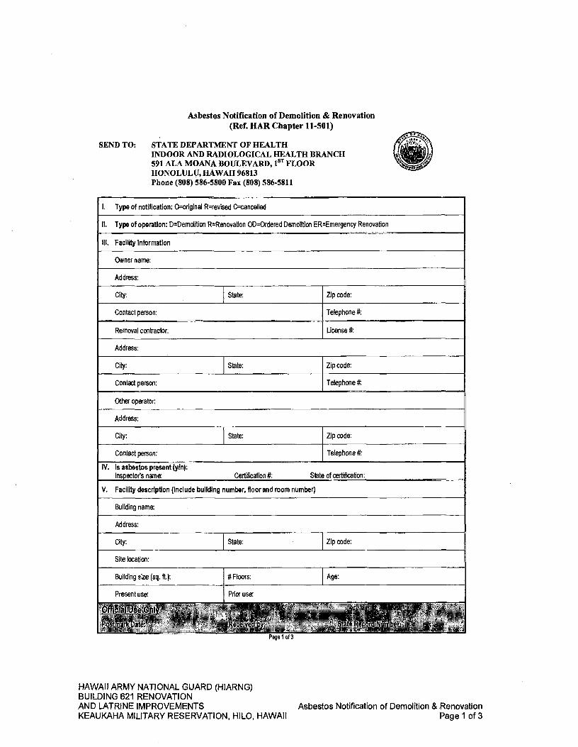
Asbestos Notification of Demolition & Renovation (Ref. HAR Chapter 11-501)
SEND TO: STATE DEPARTMENT OF HEALTH INDOOR AND RADIOLOGICAL HEALTH BRANCH 591 ALA MOANA BOULEVARD, 1ST FLOOR HONOLULU, HAWAII 96813 Phone (808) 586-5800 Fax (808) 586-5811
1. Type of notification: O=onginal R=revised C=cancelled
II. Type of operation: D=Demolition RRenovation OD=Ordered Demolition ER=Emergency Renovation
Ill. Facility information
Owner name:
Address:
City: State: Zip code:
Contact person: Telephone #:
Removal contractor: License #:
Address:
City: State: Zip code:
Contact person: Telephone it
Other operator:
Address:
City: State: Zip code:
Contact person: Telephone #:
IV. Is asbestos present (yin): Inspector's name: Certification #: State of certification:
V. Facility description (Include building number, floor and room number)
Building name:
Address:
City: State: Zip code:
Site location:
Building size (sq. ft.): # Floors: Age:
Present use: Prior use:
NE•
r
•
11-12
Mjbé V1. Wr
tj 1
Lt tiZ
Page 1 of 3
HAWAII ARMY NATIONAL GUARD (HIARNG) BUILDING 621 RENOVATION AND LATRINE IMPROVEMENTS Asbestos Notification of Demolition & Renovation KEAUKAHA MILITARY RESERVATION, HILO, HAWAII Page 1 of 3

VI. Procedure used to detect the presence of asbestos Laboratory name: Analytical method
VII. Specify the nature of the asbestos material (TSI, surfacing, VAT, miscellaneous):
including:Amount of asbestos,
1. RACM to be removed2. CAT I left In place, and
3. CAT II left in place
RACM to be removed
Nonfriable ACM not to be removed
Category I Category II
Pipes (linear ft.)
Surfacing (square ft.)
Facility components (Cu. ft.)
VIll. Scheduled asbestos abatement dates Start (mmlddlyy): Finish (mm/dd/yy)
Circle workdays and times: weekdays: daytime nighttime weekends: daytime nighttime
IX. Scheduled renovation/demolition dates Start (mm/dd/yy): Finish (mm/ddlyy)
Circle workdays and times: weekdays: daytime nighttime weekends: daytime nighttime - -
X Descrlption of the planned renovation/demolition work and methods to be used:
Yd. Description of the work practices and engineering controls to be used to prevent emissions of asbestos from the work- site:
Project designer name: - Certification M. State: -
XII. Waste transporter #1
Name:
Address:
City: State: Zipcode:
Contact Person: Telephone:
Waste transporter #2
Name:
Address:
City: State: Zipcode:
Contact Person: Telephone:
XIII. Waste disposal site:
Facility Name: Telephone:
Address:
City: State: Zipcode:
Page 2 of 3
HAWAII ARMY NATIONAL GUARD (HIARNG) BUILDING 621 RENOVATION AND LATRINE IMPROVEMENTS
Asbestos Notification of Demolition & Renovation
KEAUKAHA MILITARY RESERVATION, HILO, HAWAII
Page 2 of 3
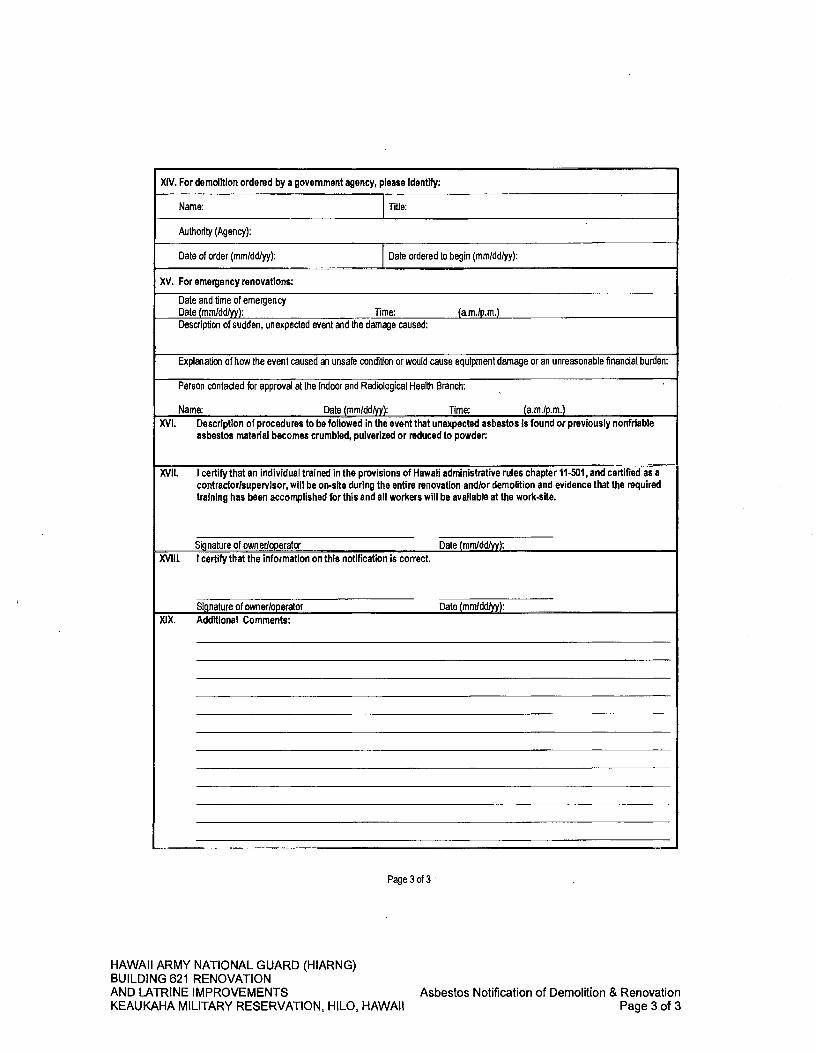
XIV. For demolition ordered by a government agency, please identify:
Name: Tide:
Authority (Agency):
Date of order (mm/ddlyy): Date ordered to begin (mm/ddlyy):
XV. For emergency renovations:
Date and time of emergency Date (mm/ddlyy): Time: (am/p.m.) Descripflon of sudden, unexpected event and the damage caused:
Explanation of how the event caused an unsafe condition or would cause equipment damage or an unreasonable financial burden:
Person contacted for approval at the Indoor and Radiological Health Branch:
Name: Date (mm/dd/yy): Time: (am/p.m.) XVI. Description of procedures to be followed in the event that unexpected asbestos Is found or previously nonfriable
asbestos material becomes crumbled, pulverized or reduced to powder:
XVII. I certify that an individual trained in the provisions of Hawaii administrative rules chapter 11-501, and certified as a contractor/supervisor, will be on-site during the entire renovation and/or demolition and evidence that the required training has been accomplished for this and all workers will be available at the work-site.
Signature of owner/operator Date (mmldd/yy): XVIII I certify that the information on this notification is correct.
Signature of owner/operator Date (mm!dd!yy): XIX. Additional Comments:
Page 3 of 3
HAWAII ARMY NATIONAL GUARD (HIARNG) BUILDING 621 RENOVATION AND LATRINE IMPROVEMENTS Asbestos Notification of Demolition & Renovation KEAUKAHA MILITARY RESERVATION, HILO, HAWAII Page 3 of 3

SECTION 02220 - SITE DEMOLITION
PART 1 - GENERAL
1.01 SUMMARY A. This section includes but is not limited to the following for site demolition:
1. Demolition and removal of building and site improvements.
2. Abandoning in-place or removing below-grade construction.
3. Disconnecting, capping or sealing, and abandoning in-place, removing, or relocating site utilities.
1.02 MATERIALS OWNERSHIP A. Unless otherwise indicated, demolition waste becomes property of the
Contractor.
B. Historic items, relics, antiques, and similar objects including, but not limited to, cornerstones and their contents, commemorative plaques and tablets, and other items of interest or value to the State that may be uncovered during demolition remain the property of the State. 1. Carefully salvage in a manner to prevent damage and promptly return to the
State.
1.03 JOB CONDITIONS A. Contractor to field verify location of all salvageable materials prior to the start of
demolition work.
1.04 SUBMITTALS A. Submit in accordance with SECTION 01330 - SUBMITTAL PROCEDURES.
B. Submit a demolition work plan to coordinate the work with the Project Manager.
PART 2- PRODUCTS
Not used.
PART 3- EXECUTION
3.01 GENERAL A. Existing Conditions:
1. The Drawings show general information only. Examine the site to determine the exact existing conditions and character and extent of the work to be performed and demolition operations required to complete the new work.
2. The failure or omission of the Contractor to visit the site and acquaint itself with the existing conditions shall in no way relieve it from obligations with respect to its bid or to the Contract.
HAWAII ARMY NATIONAL GUARD (HIARNG) BUILDING 621 RENOVATION AND LATRINE IMPROVEMENTS
Site Demolition
KEAUKAHA MILITARY RESERVATION, HILO, HAWAII
02220-1
B. Existing Utilities: 1. Existing underground lines shown on the Drawings are shown from available
information. Verify all utility line locations prior to the start of any work.
2. It is understood and agreed that certain lines cannot be or have not been located and no indication is contained on any of the Drawings or referred to in the specifications; therefore, exercise extreme caution during demolition and like work. Should any such lines be encountered, written notice shall be given to the Project Manager, and no further work in the area shall proceed until adequate investigation has been made, the line identified, and instructions are issued as to how to proceed.
3. The Contractor shall be liable for any and all damages associated with its activities which may disrupt services as a result of any utility line damage.
C. Barricades: Provide barricades, warning signs and lighting, and maintenance and supervision thereof, in accordance with applicable Federal, State and local codes, or as may be directed from time to time.
D. Equipment: The use of proper equipment is the responsibility of the Contractor.
E. Protection of Property: Existing appurtenances and improvements, which are to remain, shall be protected from damage due to work under this section.
F. Protection of Utilities: Preserve in operating condition all active utilities traversing or within and about the site; protect all such property and items, including but not limited to piping, mains, laterals, valve boxes, meters, and other appurtenances and structures. Promptly repair and notify the affected utility company of any damage to such utility or work caused by work under this Contract.
G. Protection of Plant Materials to Remain: 1. Carefully protect existing shrubs, plants, and trees within the areas of work
and site access during the course of the construction period.
2. Contractor shall be responsible for maintaining all landscaping, including shrubs and trees within the limits of work for the duration of construction. Maintaining landscape includes watering as well as protection.
3.02 DEMOLITION A. Pavement Demolition:
1. Remove from site all pavement as indicated.
2. Provide a breakline for removal of paving by machine saw-cutting the existing pavement. The depth of the saw cut shall be as required to produce a uniform breakline both vertically and horizontally.
3. Remove paving so as to prevent spalling, cracking, or other damage to adjacent paving which is to remain. The Contractor shall at its expense remove and replace damaged pavement outside the limits of removal.
HAWAII ARMY NATIONAL GUARD (HIARNG) BUILDING 621 RENOVATION AND LATRINE IMPROVEMENTS
Site Demolition
KEAUKAHA MILITARY RESERVATION, HILO, HAWAII
02220-2

4. Reuse of demolished concrete or asphalt paving as rubble fill shall not be permitted, unless otherwise accepted by the Geotechnical Engineer.
B. Utilities: 1. All existing work and items which are required to be removed shall be
removed in such manner that minimum damage and disturbance is caused to adjacent and connecting work. The Contractor shall be responsible for repairing and/or replacing all work which is damaged by these operations to the satisfaction of the Project Manager.
2. Plug or cap all existing utilities to be abandoned and not interfering with the work. Remove and dispose of existing piping within the limits of new work.
C. Structures, Chain Link Fence and Posts: All existing work and items which are required to be removed shall be removed in such manner that minimum damage and disturbance is caused to adjacent and connecting work. The Contractor shall be responsible for repairing and/or replacing all work which is damaged by these operations to the satisfaction of the Project Manager.
D. Explosives: Use of explosives is not permitted.
3.03 CLEANUP A. Removal of Demolished Material: Remove all waste material from the project
site and comply with all applicable government regulations in disposing of said waste material.
B. All materials and equipment to be removed, except that indicated to be reused or delivered as directed by the Project Manager, shall become the property of the Contractor and shall be removed from the site.
C. Remove debris resulting from this work from the site as promptly as it accumulates.
D. Cleanup: Remove all evidence of demolition work and leave areas impacted by demolition work in clean and debris-free condition.
END OF SECTION
HAWAII ARMY NATIONAL GUARD (HIARNG) BUILDING 621 RENOVATION AND LATRINE IMPROVEMENTS
Site Demolition
KEAUKAHA MILITARY RESERVATION, HILO, HAWAII
02220-3

SECTION 02230 - SITE CLEARING
PART 1 - GENERAL
1.01 SUMMARY A. This section includes but is not limited to the following for site clearing:
1. Protecting existing vegetation to remain.
2. Removing existing vegetation.
3. Clearing and grubbing.
4. Stripping and stockpiling topsoil.
5. Removing above-grade site improvements
6. Temporary erosion and sedimentation control measures.
B. Related Work Described Elsewhere: 1. SECTION 01500 - TEMPORARY FACILITIES AND CONTROLS for
temporary utility services, construction and support facilities, security and protection facilities, and temporary erosion- and sedimentation-control measures.
2. SECTION 01524 - CONSTRUCTION WASTE MANAGEMENT for field engineering and surveying.
3. SECTION 01700 - EXECUTION REQUIREMENTS for field engineering and surveying.
4. SECTION 02220 - SITE DEMOLITION for demolition of structures and site improvements.
1.02 DEFINITIONS A. Subsoil: All soil beneath the topsoil layer of the soil profile and typified by the
lack of organic matter and soil organisms.
B. Surface Soil: Soil that is present at the top layer of the existing soil profile at the project site. In undisturbed areas, the surface soil is typically topsoil; but in disturbed areas such as urban environments, the surface soil can be subsoil.
C. Topsoil: Top layer of the soil profile consisting of existing native surface topsoil or existing in-place surface soil and is the zone where plant roots grow. Its appearance is generally friable, pervious, and black or a darker shade of brown, gray, or red than underlying subsoil; reasonably free of subsoil, clay lumps, gravel, and other objects more than two (2) inches in diameter; and free of subsoil and weeds, roots, toxic materials, or other non-soil materials.
D. Vegetation: Trees, shrubs, groundcovers, grass, and other plants.
HAWAII ARMY NATIONAL GUARD (HIARNG) BUILDING 621 RENOVATION AND LATRINE IMPROVEMENTS
Site Clearing
KEAUKAHA MILITARY RESERVATION, HILO, HAWAII
02230-1

1.03 DESCRIPTION A. Clearing: This item includes but is not limited to clearing and disposing of all
materials, vegetation, debris, rubbish, and other unsuitable material; removing of trash piles and other obstructions interfering with the proposed work to the limits shown on the Drawings.
B. Grubbing: This item includes but is not limited to the removal of tree stumps, large roots, buried logs, junk, and other objectionable materials at or below the ground surface not prescribed under the item of "Clearing" to the limits shown on the Drawings.
1.04 MATERIAL OWNERSHIP A. Except for stripped topsoil and other materials indicated to be stockpiled or
otherwise remain the State's property, cleared materials shall become the Contractor's property and shall be removed from the project site.
1.05 SUBMITTALS A. Submit in accordance with SECTION 01330 - SUBMITTAL PROCEDURES.
B. Existing Conditions: Documentation of existing trees and plantings, adjoining construction, and site improvements that establishes preconstruction conditions that might be misconstrued as damage caused by site clearing. 1. Use sufficiently detailed photographs or videotape.
C. Record Drawings: Identifying and accurately showing locations of capped utilities and other subsurface structural, electrical, and mechanical conditions.
1.06 PROJECT CONDITIONS A. Traffic: Minimize interference with adjoining roads, streets, walks, and other
adjacent occupied or used facilities during site-clearing operations. 1. Do not close or obstruct streets, walks, or other adjacent occupied or used
facilities without permission from the Project Manager and authorities having jurisdiction.
2. Provide alternate routes around closed or obstructed traffic ways if required by the Project Manager or authorities having jurisdiction.
B. Do not commence site clearing operations until temporary erosion and sedimentation-control measures are in place.
PART 2- PRODUCTS
Not used.
PART 3- EXECUTION
3.01 SITE CLEARING A. General: Remove vegetation, debris, rubbish and trees, shrubs, grass and other
vegetation, or obstruction interfering with the limits shown on the Drawings.
HAWAII ARMY NATIONAL GUARD (HIARNG) BUILDING 621 RENOVATION AND LATRINE IMPROVEMENTS
Site Clearing
KEAUKAHA MILITARY RESERVATION, HILO, HAWAII
02230-2
B. Clearing and Grubbing: 1. Clear site of vegetation.
2. Strip and remove the organically contaminated near-surface soils to a minimum depth of two (2) to six (6) inches.
3. Remove trees and roots to a minimum of 3-feet below existing ground level. Remove all large roots in excess of two (2) inches in diameter.
4. Except in excavation areas, backfill all trenches, holes, depressions or pits resulting from clearing and grubbing operations with satisfactory soils, according to the requirements of SECTION 02300 - EARTHWORK, or as directed by the Geotechnical Engineer.
3.02 DISPOSAL OF WASTE MATERIALS A. Burning of Debris: Burning of debris is not permitted.
B. Removal of Waste Material: Remove all waste material from the project site and comply with all applicable government regulations in disposing of said waste material.
C. Remove all evidence of demolition work and restore areas impacted. Leave the areas in a clean and debris-free condition.
END OF SECTION
HAWAII ARMY NATIONAL GUARD (HIARNG) BUILDING 621 RENOVATION AND LATRINE IMPROVEMENTS
Site Clearing
KEAUKAHA MILITARY RESERVATION, HILO, HAWAII
02230-3
SECTION 02287 - TERMITE CONTROL BARRIER SYSTEM
PART I -GENERAL
1.01 SUMMARY A. Provide non-chemical termite control mesh physical barrier system complete in
place. For termite protection, irrespective if using a termite system such as Termiticide, all conduit and pipe penetrations and slab expansion and construction joints shall have termimesh protection installed.
B. Chemical termite treatment is provided under SECTION 02361 - TERMITE CONTROL.
C. The Contractor shall prepare all design drawings and modifications, as necessary, adjust foundation details accordingly, and prepare the necessary shop drawings for the installation of the termite control barrier system specified herein. 1. All mesh treatment details, configurations, and locations are not shown.
2. The mesh treatment system must be installed in accordance with the manufacturer's standard for a total protective system which the manufacturer will warrant in accordance with contract specifications.
D. Related Work Described Elsewhere: Coordinate installation of the mesh termite control system with other termite control systems described in DIVISION 2 - SITE CONSTRUCTION, earthwork and other below slab construction described in DIVISION 2 - SITE CONSTRUCTION, concrete work as described in DIVISION 3 - CONCRETE, plumbing systems as described in DIVISION 15 - MECHANICAL, electrical systems as described in DIVISION 16- ELECTRICAL, and all other penetrations of the mesh termite control barrier system or work that affects the effectiveness of the system with the applicable technical section or drawing.
1.02 SUBMITTALS A. Submit in accordance with SECTION 01330 - SUBMITTAL PROCEDURES.
B. Manufacturer's Data: Submit manufacturer's product data and installation instructions.
C. Shop Drawings: Submit shop drawings for all installation conditions, including perimeter, joints, and penetration conditions. Include details for form work, joints, connections, and clamps. Show anchorage and accessory items.
D. Instructions: Submit manufacturer's installation instructions.
E. Qualifications of Barrier System Installers Applicator: Submit data as required in paragraph entitled "Qualifications of System Installers" hereinbelow.
HAWAII ARMY NATIONAL GUARD (HIARNG) BUILDING 621 RENOVATION AND LATRINE IMPROVEMENTS
Termite Control Barrier System
KEAUKAHA MILITARY RESERVATION, HILO, HAWAII
02287-1
F. Sample: Submit 12-inch square sample of material with recommended joint down the center.
G. Inspection Reports: Inspection reports by the manufacturer's representative certifying that the work has been installed in accordance with all manufacturer's requirements in support of the warranty.
H. Material Safety Data Sheets (MSDS): Submit MSDS for each product as applicable.
I. Record Drawings: Provide record drawings of all mesh treatment for termite control.
J. Warranty: Submit warranty as stipulated in item entitled "WARRANTY" hereinbelow.
1.03 QUALITY ASSURANCE A. Qualifications of System Installers: The installer shall be trained and accredited
by the mesh treatment termite control barrier system manufacturer. The installer shall employ only workers trained and accredited at the appropriate level by the termite control barrier system manufacturer.
B. System Description: A fine stainless mesh is placed across all termite entry points to the building, including penetrations through concrete slab-on-grade, across cavities of walls, along the perimeter of concrete slabs-on-grade where they abut walls and columns, and expansion and control joints. The mesh shall be too fine for the termites to squeeze through, too hard to chew through, and corrosive resistant to chemical attack.
1.04 DELIVERY, STORAGE, AND HANDLING A. Deliver materials to the building site in the manufacturer's unopened bundles and
containers with the manufacturer's brand name marked clearly thereon.
B. Keep materials dry, covered completely, and protected from the weather. Store according to manufacturer's written instructions.
C. Protect materials as recommended by the manufacturer after installation before overlaying materials are installed.
1.05 WARRANTY A. The Contractor shall furnish a written warranty in 3 copies to the State stating
that: 1. The method of installation complied with these specifications;
2. The effectiveness of the treatment is warranted for a period of not less than I year from the date of project acceptance;
3. All necessary repairs of damages resulting from subterranean termite infestation within the warranty period will be made at the Contractor's own expense up to a total cost of $5,000.00;
HAWAII ARMY NATIONAL GUARD (HIARNG) BUILDING 621 RENOVATION AND LATRINE IMPROVEMENTS
Termite Control Barrier System
KEAUKAHA MILITARY RESERVATION, HILO, HAWAII
02287- 2
4. If subterranean termite infestation should occur through the treated area within the warranty period, the soil shall be treated to exterminate all infestation without additional cost to the State. The application rates shall be as given by the label of the chemical being used. All corrective treatments shall be performed to at least 10-feet around each visible subterranean termite activity; and
5. The manufacturer shall warrant the materials from deterioration and failure for 10 years.
6. The Surety shall not be liable beyond 2 years from the project acceptance date.
B. An investigation shall be made by the Contractor for all reported termite damage during the warranty period.
C. At the completion of such investigation and regular inspection, the Contractor shall submit a report prepared on Contractor furnished standardized forms to the State. The report shall include the following information: 1. Date of the investigation/inspection.
2. Name and signature of the mechanic performing the investigation/inspection.
3. Listing and description of the deficiencies observed, their location and of what corrective action was taken. This description shall be sufficiently detailed to accurately reflect the location, findings, and work performed.
D. Repairs shall be made to cracks through the slab-on-grade or foundation walls that permit termite entry and the elimination of all termite infestation.
1.06 PRE-INSTALLATION MEETING A. No less than one week prior to beginning installation, convene a pre-installation
meeting at the construction site attended by the Contractor, Project Manager, the installer, and the installer's crew leader, and representatives of the trades affected by this work. Review conditions of preparation, storage and handling, installation procedures, sequencing, protection, and coordination with related work.
PART 2- PRODUCTS
2.01 MATERIALS A. Mesh: ASTM A 478 or ASTM A 580/A 580M, Type 316 stainless steel mesh,
0.007-inch (0.18 mm) diameter wire with 0.026-inch by 0.018-inch (0.66 mm by 0.45 mm) openings as manufactured by Termi-Mesh and distributed by Termi Mesh Hawaii Inc. or accepted equivalent.
B. Hot Glue: As recommended by the manufacturer.
HAWAII ARMY NATIONAL GUARD (HIARNG) BUILDING 621 RENOVATION AND LATRINE IMPROVEMENTS
Termite Control Barrier System
KEAUKAHA MILITARY RESERVATION, HILO, HAWAII
02287-3

C. Stainless Steel Clamp: As recommended by the manufacturer.
D. Accessories: Ties and other accessories shall be as recommended by the manufacturer.
PART 3- EXECUTION
3.01 SURFACE CONDITIONS A. Examination: Examine the substrates and conditions under which work of this
section will be performed. Do not proceed until unsatisfactory conditions detrimental to timely and proper completion of the work has been corrected.
B. Verification: Verify that the condition of the site under proposed slabs is proper for the installation of termite control barrier system and that the following are complete. 1. Remove all non-essential wood and cellulose containing material from area.
2. The site has been compacted and cushion fill has been placed.
3. Footings and foundations and other forms are in place.
4. All electrical, plumbing, and other penetrations through slabs are in place.
3.02 INSTALLATION A. Installation shall be in accordance with the manufacturer's printed instructions in
Manufacturer's Installation Notes.
B. Application at Joints: Install mesh at expansion and control joints of slabs-on-grade, including perimeter of slab where it abuts walls, all foundation walls, and at all pipe and conduit penetrations of slabs-on-grade, atop the first masonry course above grade where the masonry wall extends below grade, on the eterior surface of basement or pit masonry walls as recommended by the manufacturer with the least number of joints. Joints shall be lapped two and a half times 0.39 - 0.59 inch (10 - 15 mm physical lap) as shown on manufacturer's printed instructions. Provide hot glue gun reinforcement every 19-1/2 - 39 inches (500 - 1000 mm) along each joint.
C. Application at Penetrations: Locate at all conduit and pipe penetrations. Provide prefabricated penetration mesh for single and multiple penetrations of the size and spacing found at the site.
D. Sequence of Operations: 1. Install stainless steel mesh, fit and clamp mesh around all pipe penetrations,
and terminate at perimeters as appropriate for the building construction.
2. Install special fittings as appropriate to construction.
HAWAII ARMY NATIONAL GUARD (HIARNG) BUILDING 621 RENOVATION AND LATRINE IMPROVEMENTS
Termite Control Barrier System
KEAUKAHA MILITARY RESERVATION, HILO, HAWAII
02287-4

3. Vapor barrier, reinforcing steel, and concrete shall be installed in conjunction with placement of stainless steel mesh as recommended by the manufacturer.
4. Where required, integrate stainless steel mesh into subsequent construction.
3.03 PROTECTION A. Protect the installed stainless steel mesh and attachments before, during, and
after the work of other trades.
3.04 FIELD QUALITY CONTROL A. Prior to placement of concrete, masonry, and any overlaying construction over
the stainless steel barrier system, ensure that the termite control barrier system is undamaged and intact in accordance with the manufacturer's recommendations. Installation shall be approved by the manufacturer's representative. Correct all damaged areas in accordance with manufacturer's recommendations as accepted by the Project Manager.
3.05 VISUAL INSPECTION GUIDE A. To maintain resistance to termites, the system shall be complete and not
disturbed, penetrated or damaged during the remaining contract time period. The installer shall provide manufacturer's guidance for performing a visual assessment of the installed mesh termite control barrier to ensure the mesh barrier provides the designed termite physical barrier.
3.06 REPAIRS A. If live subterranean termite entry is discovered during the warranty period, the
Contractor shall provide an evaluation of the site and repair the installed mesh barrier system and any damage occurred, as required.
END OF SECTION
HAWAII ARMY NATIONAL GUARD (HIARNG) BUILDING 621 RENOVATION AND LATRINE IMPROVEMENTS
Termite Control Barrier System
KEAUKAHA MILITARY RESERVATION, HILO, HAWAII
02287-5
SECTION 02300 - EARTHWORK
PART 1 - GENERAL
1.01 SUMMARY A. This section includes but is not limited to the following for earthwork.
1. Preparing subgrades for slabs-on-grade, walks, pavements, turf and grasses and plants.
2. Excavating and backfilling for buildings and structures.
3. Drainage course for concrete slabs-on-grade.
4. Base course for concrete walks and pavements.
5. Base course for asphalt paving.
6. Subsurface drainage backf ill for walls and trenches.
7. Excavating and backfilling trenches for utilities and pits for buried utility structures.
8. Taking all precautions needed to prevent dust nuisance to occupied areas of the site and adjacent properties and prevent erosion of soil by water and wind and transport to adjacent properties by construction traffic. Any damage so caused shall be corrected and repaired by the Contractor at no cost to the project.
B. Related Work Described Elsewhere: 1. SECTION 02220 - SITE DEMOLITION. Requirements for disposal of cleared
and grubbed materials resulting from work under this section.
2. SECTION 02230 - SITE CLEARING. Requirements for site preparation.
3. SECTION 02740 - ASPHALT CONCRETE PAVING and SECTION 02750 - PORTLAND CEMENT. Requirements for final surfacing of the sub-grades prepared in accordance with the requirements herein.
4. SECTION 02900 - PLANTING. Requirements for topsoil and placement thereof in areas outside of buildings, structures, and pavements.
C. Earthwork for water lines under this section is specified in DIVISION 300, SECTION-302 of the Department of Water Supply, County of Hawaii, et al., Water System Standards, 2002, hereinafter referred to as the "DWS Standards". All references made to "Engineer" in the DWS Standards shall be replaced by "Project Manager". Paragraphs on measurement and payment do not apply.
D. Earthwork for electrical, communication and associated lines shall be as indicated and specified in DIVISION 16 - ELECTRICAL.
HAWAII ARMY NATIONAL GUARD (HIARNG) BUILDING 621 RENOVATION AND LATRINE IMPROVEMENTS Earthwork KEAUKAHA MILITARY RESERVATION, HILO, HAWAII 02300-1
1.02 DEFINITIONS A. Backfill: Soil material or controlled low-strength material used to fill an
excavation. 1. Initial Backfill: Backfill placed beside and over pipe in a trench, including
haunches to support sides of pipe.
2. Final Backfill: Backfill placed over initial backfill to fill a trench.
B. Base Course: Aggregate layer placed between the subgrade and hot-mix asphalt paving or concrete paving.
C. Bedding Course: Aggregate layer placed over the excavated subgrade in a trench before laying pipe.
D. Borrow Soil: Satisfactory soil imported from off-site for use as fill or backfill.
E. Drainage Course: Aggregate layer supporting the slab-on-grade that also minimizes upward capillary flow of pore water.
F. Excavation: Removal of material encountered above subgrade elevations and to lines and dimensions indicated. 1. Authorized Additional Excavation: Excavation below subgrade elevations or
beyond indicated lines and dimensions as directed by the Project Manager. Authorized additional excavation and replacement material will be paid for according to Contract provisions for unit prices.
2. Bulk Excavation: Excavation more than ten (10) feet in width and more than thirty (30) feet in length.
3. Unauthorized Excavation: Excavation below subgrade elevations or beyond indicated lines and dimensions without direction by the Project Manager. Unauthorized excavation, as well as remedial work directed by the Project Manager, shall be without additional compensation.
G. Fill: Soil materials used to raise existing grades.
H. Rock: Dense material in beds, ledges, unstratified masses, conglomerate deposits, and boulders of rock material 3/4 cubic yard or more in volume that exceed a standard penetration resistance of 100 blows/2-inches when tested by a geotechnical testing agency, according to ASTM D 1586/ Dl 586M-1 8.
I. Structures: Buildings, footings, foundations, retaining walls, slabs, tanks, curbs, mechanical and electrical appurtenances, or other man-made stationary features constructed above or below the ground surface.
J. Subgrade: Uppermost surface of an excavation or the top surface of a fill or backfill immediately below base, drainage fill, drainage course, or topsoil materials.
K. Utilities: On-site underground pipes, conduits, ducts, and cables, as well as underground services within buildings.
HAWAII ARMY NATIONAL GUARD (HIARNG) BUILDING 621 RENOVATION AND LATRINE IMPROVEMENTS Earthwork KEAUKAHA MILITARY RESERVATION, HILO, HAWAII 02300-2

1.03 DESCRIPTION A. Work under this section consists of furnishing all labor, materials, and equipment
required to complete the earthwork shown on the Drawings, or specified herein, including the following: 1. Excavating, filling, backfilling, rough and finish grading, overhauling and
stockpiling, and related items necessary to complete the site grading shown on the Drawings and specified herein.
B. All grading work under this section shall conform to the local County Grading Ordinances and the applicable Standard Specifications unless otherwise specified or modified within the geotechnical investigation report.
1.04 SUBMITTALS A. Submit in accordance with SECTION 01330 - SUBMITTAL PROCEDURES.
B. Submit the name of the independent Geotechnical Engineer to be employed by the Contractor to perform testing, reports, etc. The Geotechnical Engineer shall be approved by the Project Manager prior to commencing any work.
C. Product Data: For each type of the following manufactured products required: 1. Warning tapes.
D. Samples for Verification: For the following products, in sizes indicated below: 1. Warning Tape: Twelve (12) inches long, of each color.
E. Qualification Data: For qualified testing agency.
F. Material Test Reports: For each on-site and borrow soil material proposed for fill and backfill as follows: 1. Classification according to ASTM D 2487-17.
2. Laboratory compaction curve according to ASTM D 1557-1 2e1.
3. Laboratory CBR test results according to ASTM D 1833-87(2017) for borrow material.
G. Pre-excavation Photographs or Videotape: Show existing conditions of adjoining construction and site improvements, including finish surfaces, that might be misconstrued as damage caused by earth moving operations. Submit before earth moving begins.
1.05 QUALITY ASSURANCE A. Geotechnical Engineer Qualifications: Qualified according to ASTM E 329-18
and ASTM D 3740-12a for testing indicated.
B. Preexcavation Conference: Conduct conference at the project site.
1.06 PROJECT CONDITIONS A. Traffic: Minimize interference with adjoining roads, streets, walks, and other
adjacent occupied or used facilities during earth moving operations.
HAWAII ARMY NATIONAL GUARD (HIARNG) BUILDING 621 RENOVATION AND LATRINE IMPROVEMENTS Earthwork KEAUKAHA MILITARY RESERVATION, HILO, HAWAII 02300-3

1. Do not close or obstruct streets, walks, or other adjacent occupied or used facilities without permission from the Project Manager and authorities having jurisdiction.
2. Provide alternate routes around closed or obstructed traffic ways if required by the Project Manager or authorities having jurisdiction.
B. Do not commence earth moving operations until temporary erosion- and sedimentation-control measures are in place.
C. The following practices are prohibited within protection zones: 1. Storage of construction materials, debris, or excavated material.
2. Parking vehicles or equipment.
3. Foot traffic.
4. Erection of sheds or structures.
5. Impoundment of water.
6. Excavation or other digging unless otherwise indicated.
7. Attachment of signs to or wrapping materials around trees or plants unless otherwise indicated.
D. Do not direct vehicle or equipment exhaust towards protection zones.
E. Prohibit heat sources, flames, ignition sources, and smoking within or near protection zones.
1.07 UNFORESEEN CONDITIONS BELOW GRADE A. Unforeseen soil conditions such as voids or cavities, areas of soft soils and
materials, seepage water, expansive soil pockets, and similar conditions, may be encountered below or at existing grade. Corrective measures shall be made in the field as the conditions are detected in accordance with the requirements herein, or as directed by the Geotechncial Engineer. These corrective measures shall be considered as incidental to the contract price.
PART 2- PRODUCTS
2.01 SOIL MATERIALS A. General: Provide borrow soil materials when sufficient satisfactory soil materials
are not available from excavations.
B. Satisfactory Soils: Soil Classification Groups GW, GM, GW-GM, GP-GM, SW, SW-SM, SP-SM, and SM according to ASTM D 2487-17, or a combination of these groups; free of rock or gravel larger than three (3) inches in any dimension, debris, waste, frozen materials, vegetation, and other deleterious matter. 1. Liquid Limit: Twenty-five (25) or less.
HAWAII ARMY NATIONAL GUARD (HIARNG) BUILDING 621 RENOVATION AND LATRINE IMPROVEMENTS Earthwork KEAUKAHA MILITARY RESERVATION, HILO, HAWAII 02300-4

2. Plasticity Index: Ten (10) or less.
3. CBR expansion: CBR expansion shall be less than one (1) percent when tested in accordance with ASTM D 1883-16.
C. Unsatisfactory Soils: Soil Classification Groups GC, SC, CL, ML, OL, CH, MH, OH, and PT according to ASTM D 2487-17, or a combination of these groups. 1. Unsatisfactory soils also include satisfactory soils not maintained within 2
percent of optimum moisture content at time of compaction.
D. Base Course: Naturally or artificially graded mixture of natural or crushed gravel, crushed stone, and natural or crushed sand, ASTM D 2940/D 2940M-1 5 with at least ninety-five (95) percent passing a 1-1/2 inch sieve and not more than eight (8) percent passing a No. 200 sieve. Base course shall have a minimum CBR value of eighty-five (85). CBR expansion shall be less than one (1.0) percent when tested in accordance with ASTM D 1883-16.
E. Imported Fill: Naturally or artificially graded mixture of natural or crushed gravel, crushed stone, and natural or crushed sand, with one hundred (100) percent passing a three (3) inch sieve, and between eight (8) 'and twenty (20) percent passing a No. 200 sieve. The Plasticity Index (P1) of that portion of soil passing the No. 40 sieve shall not be greater than ten (10). Engineering fill shall also have a minimum CBR value of fifteen (15). CBR expansion shall be less than one (1.0) percent when tested in accordance with ASTM D 1883-16.
F. Bedding Course: 1. For Sewer and Storm- Drainage Systems: Naturally or artificially graded
mixture of natural or crushed gravel, crushed stone, and natural or crushed sand, ASTM D 2940/D 2940M-1 5 except with one hundred (100) percent passing a one (1) inch sieve and not more than eight (8) percent passing a No. 200 sieve.
2. For Water Lines: as specified in the DWS Standards.
G. Cushion Material: Meet the gradation requirements of concrete-course aggregates as specified in ASTM C33/C 33M-1 8, size No. 67.
H. Drainage Course: Narrowly graded mixture of washed crushed stone, or crushed or uncrushed gravel, ASTM D 448-12(2017) coarse-aggregate grading Size 67 with 100 percent passing a 1-inch sieve and 0 to 5 percent passing a No. 8 sieve.
I. Filter Material: Narrowly graded mixture of natural or crushed gravel, or crushed stone and natural sand, ASTM D 448-12(2017) coarse-aggregate grading Size 67 with one hundred (100) percent passing a one (1) inch sieve and zero (0) to five (5) percent passing a No. 4 sieve.
J. Sand: ASTM C33/C 33M-18, fine aggregate.
K. Impervious Fill: Cohesive soil with low expansion potential.
HAWAII ARMY NATIONAL GUARD (HIARNG) BUILDING 621 RENOVATION AND LATRINE IMPROVEMENTS Earthwork KEAUKAHA MILITARY RESERVATION, HILO, HAWAII 02300-5

2.02 ACCESSORIES A. Warning Tape: Acid- and alkali-resistant, polyethylene film warning tape
manufactured for marking and identifying underground utilities, six (6) inches wide and four (4) mils thick continuously inscribed with a description of the utility; colored as follows: 1. Red: Electric.
2. Yellow: Gas, oil, steam, and dangerous materials.
3. Orange: Telephone and other communications.
4. Blue: Water systems.
5. Green: Sewer systems.
B. Detectable Warning Tape: Acid- and alkali-resistant, polyethylene film warning tape manufactured for marking and identifying underground utilities, a minimum of six (6) inches wide and four (4) mils thick, continuously inscribed with a description of the utility, with metallic core encased in a protective jacket for corrosion protection, detectable by metal detector when tape is buried up to thirty (30) inches deep; colored as follows: 1. Red: Electric.
2. Yellow: Gas, oil, steam, and dangerous materials.
3. Orange: Telephone and other communications.
4. Blue: Water systems.
5. Green: Sewer systems.
PART 3- EXECUTION
3.01 PREPARATION A. Protect structures, utilities, sidewalks, pavements, and other facilities from
damage caused by settlement, lateral movement, undermining, washout, and other hazards created by earth moving operations.
B. Protect and maintain erosion and sedimentation controls during earth moving operations.
3.02 EXPLOSIVES A. Explosives: Use of explosives is not permitted.
3.03 EXCAVATION, GENERAL A. Unclassified Excavation: Excavate to subgrade elevations regardless of the
character of surface and subsurface conditions encountered. Unclassified excavated materials may include rock, soil materials, and obstructions. No changes in the Contract Sum or the Contract Time will be authorized for rock excavation or removal of obstructions.
HAWAII ARMY NATIONAL GUARD (HIARNG) BUILDING 621 RENOVATION AND LATRINE IMPROVEMENTS Earthwork KEAUKAHA MILITARY RESERVATION, HILO, HAWAII 02300-6

1. If excavated materials intended for fill and backfill include unsatisfactory soil materials and rock, replace with satisfactory soil materials.
2. Remove rock to lines and grades indicated to permit installation of permanent construction without exceeding the following dimensions: a. Twenty-four (24) inches outside of concrete forms other than at footing.
b. Twelve (12) inches outside of concrete forms at footings.
c. Six (6) inches outside of minimum required dimensions of concrete cast against grade.
d. Outside dimensions of concrete walls indicated to be cast against rock without forms or exterior waterproofing treatments.
e. Six (6) inches beneath bottom of concrete slabs-on-grade.
f. Six (6) inches beneath pipe and twenty-four (24) inches wider than pipe in trenches.
3.04 EXCAVATION FOR STRUCTURES A. Excavate to indicated elevations and dimensions within a tolerance of plus or
minus one (1) inch. If applicable, extend excavations a sufficient distance from structures for placing and removing concrete formwork, for installing services and other construction, and for inspections. 1. Excavations for Footings and Foundations: Excavate foundations twelve (12)
inches deeper than bottom of foundations elevations to allow for structural fill placement.
2. Excavation for Underground Tanks, Basins, and Mechanical or Electrical Utility Structures: Excavate to elevations and dimensions indicated within a tolerance of plus or minus one (1) inch. Do not disturb bottom of excavations intended as bearing surfaces.
B. Excavations at Edges of Tree- and Plant-Protection Zones: 1. Excavate by hand to indicated lines, cross sections, elevations, and
subgrades or as required for protection of the vegetation to remain. Use narrow-tine spading forks to comb soil and expose roots. Do not break, tear, or chop exposed roots. Do not use mechanical equipment that rips, tears, or pulls roots.
3.05 EXCAVATION FOR WALKS AND PAVEMENTS A. Excavate surfaces under walks and pavements to indicated lines, cross sections,
elevations, and subgrades.
3.06 EXCAVATION FOR UTILITY TRENCHES A. Excavate trenches to indicated gradients, lines, depths, and elevations.
HAWAII ARMY NATIONAL GUARD (HIARNG) BUILDING 621 RENOVATION AND LATRINE IMPROVEMENTS Earthwork KEAUKAHA MILITARY RESERVATION, HILO, HAWAII 02300-7
B. Excavate trenches to uniform widths to provide the following clearance on each side of pipe or conduit. Excavate trench walls vertically from trench bottom to twelve (12) inches higher than top of pipe or conduit unless otherwise indicated. 1. Clearance: As indicated.
C. Trench Bottoms: Excavate and shape trench bottoms to provide uniform bearing and support of pipes and conduit. Shape subgrade to provide continuous support for bells, joints, and barrels of pipes and for joints, fittings, and bodies of conduits. Remove projecting stones and sharp objects along trench subgrade. 1. For pipes and conduit less than six (6) inches in nominal diameter, hand-
excavate trench bottoms and support pipe and conduit on an undisturbed subgrade.
2. For pipes and conduit six (6) inches or larger in nominal diameter, shape bottom of trench to support bottom ninety (90) degrees of pipe or conduit circumference. Fill depressions with tamped sand backfill.
3. For flat-bottomed, multiple-duct conduit units, hand-excavate trench bottoms and support conduit on an undisturbed subgrade.
4. In rock or other unyielding bearing material to allow for bedding course excavate trenches 6-inches deeper than elevation required.
D. Trench Bottoms: Excavate trenches four (4) inches deeper than bottom of pipe and conduit elevations to allow for bedding course. Hand-excavate deeper for bells of pipe. 1. Excavate trenches six (6) inches deeper than elevation required in rock or
other unyielding bearing material to allow for bedding course.
E. Trenches in Tree- and Plant-Protection Zones: 1. Hand-excavate to indicated lines, cross sections, elevations, and subgrades.
Use narrow-tine spading forks to comb soil and expose roots. Do not break, tear, or chop exposed roots. Do not use mechanical equipment that rips, tears, or pulls roots.
2. Do not cut main lateral roots or taproots; cut only smaller roots that interfere with installation of utilities.
3.07 SUBGRADE INSPECTION A. Notify the Project Manager when excavations have reached required subgrade.
B. If the Project Manager determines that unsatisfactory soil is present, continue excavation and replace with compacted backf ill or fill material as directed.
C. Proof-roll subgrade below the building slabs and pavements with a pneumatic-tired and loaded ten (10)-wheel, tandem-axle dump truck weighing not less than fifteen (15) tons to identify soft pockets and areas of excess yielding. Do not proof-roll wet or saturated subgrades. 1. Completely proof-roll subgrade in one direction, repeating proof-rolling in
direction perpendicular to first direction. Limit vehicle speed to three (3) mph.
HAWAII ARMY NATIONAL GUARD (HIARNG) BUILDING 621 RENOVATION AND LATRINE IMPROVEMENTS Earthwork KEAUKAHA MILITARY RESERVATION, HILO, HAWAII 02300-8

2. Excavate soft spots, unsatisfactory soils, and areas of excessive pumping or rutting, as determined by the Project Manager, and replace with compacted backf ill or fill as directed.
D. Authorized additional excavation and replacement material will be paid for according to Contract provisions for unit prices.
E. Reconstruct subgrades damaged by rain, accumulated water, or construction activities, as directed by the Project Manager, without additional compensation.
3.08 UNAUTHORIZED EXCAVATION A. Fill unauthorized excavation under foundations or wall footings by extending
bottom elevation of concrete foundation or footing to excavation bottom, without altering top elevation. Lean concrete fill, with 28-day compressive strength of 2500 psi, may be used when approved by the Project Manager. 1. Fill unauthorized excavations under other construction, pipe, or conduit as
directed by the Project Manager.
3.09 STORAGE OF SOIL MATERIALS A. Stockpile borrow soil materials and excavated satisfactory soil materials without
intermixing. Place, grade, and shape stockpiles to drain surface water. Cover to prevent windblown dust. 1. Stockpile soil materials away from edge of excavations. Do not store within
drip line of trees to remain.
3.10 BACKFILL A. Place and compact backf ill in excavations promptly, but not before completing
the following: 1. Construction below finish grade including, where applicable, subdrainage,
dam pproofing, waterproofing, and perimeter insulation.
2. Surveying locations of underground utilities for Record Documents.
3. Testing and inspecting underground utilities.
4. Removing concrete formwork.
5. Removing trash and debris.
6. Removing temporary shoring and bracing, and sheeting.
7. Installing permanent or temporary horizontal bracing on horizontally supported walls.
B. Place backf ill on subgrades free of mud.
3.11 UTILITY TRENCH BACKFILL A. Place backfill on subgrades free of mud.
HAWAII ARMY NATIONAL GUARD (HIARNG) BUILDING 621 RENOVATION AND LATRINE IMPROVEMENTS Earthwork KEAUKAHA MILITARY RESERVATION, HILO, HAWAII 02300-9

B. Place and compact bedding course on trench bottoms and where indicated. Shape bedding course to provide continuous support for bells, joints, and barrels of pipes and for joints, fittings, and bodies of conduits.
C. Trenches Under Footings: Backf ill trenches excavated under footings and below 24-inches of bottom of footings with satisfactory soil; fill the remainder with concrete to elevation of bottom of footings. Concrete is specified in SECTION 03300 - CAST-IN-PLACE CONCRETE.
D. Backf ill voids with satisfactory soil while removing shoring and bracing.
E. Place and compact initial backfill of satisfactory soil, free of particles larger than 1-inch in any dimension, to a height of twelve (12) inches over the pipe or conduit. 1. Carefully compact initial backfill under pipe haunches and compact evenly up
on both sides and along the full length of piping or conduit to avoid damage or displacement of piping or conduit. Coordinate backfilling with utilities testing.
F. Place and compact final backfill of satisfactory soil to final subgrade elevation.
G. Install warning tape directly above utilities, twelve (12) inches above top of pipe.
3.12 SOIL FILL A. Plow, scarify, bench, or break up sloped surfaces steeper than one (1) vertical to
five (5) horizontal so fill material will bond with existing material.
B. Place and compact fill material in layers to required elevations as follows: 1. Under grass and planted areas, use top soil as specified in SECTION 02900 -
PLANTING.
2. Under walks and pavements, use satisfactory soil material.
3. Under steps and ramps, use satisfactory soil material.
4. Under building slabs, use satisfactory soil material.
5. Under footings and foundations, use satisfactory soil material.
C. Place soil fill on subgrades free of mud.
3.13 SOIL MOISTURE CONTROL A. Moisture condition the material to about two (2) percent above optimum moisture
content. 1. Do not place backfill or fill soil material on surfaces that are muddy.
2. Remove and replace, or scarify and air dry, otherwise satisfactory soil material that is too wet to compact to specified dry unit weight.
HAWAII ARMY NATIONAL GUARD (HIARNG) BUILDING 621 RENOVATION AND LATRINE IMPROVEMENTS Earthwork KEAUKAHA MILITARY RESERVATION, HILO, HAWAII 02300-10

3.14 COMPACTION OF SOIL BACKFILLS AND FILLS A. Place backf ill and fill soil materials in layers not more than eight (8) inches in
loose depth for material compacted by heavy compaction equipment, and not more than four (4) inches in loose depth for material compacted by hand-operated tampers.
B. Place backf ill and fill soil materials evenly on all sides of structures to required elevations, and uniformly along the full length of each structure.
C. Compact soil materials to not less than the following percentages of maximum dry unit weight according to ASTM D 1557-12e1: 1. Under structures, building slabs, steps, and pavements, scarify and
recompact top twelve (12) inches of existing subgrade and each layer of backf ill or fill soil material to a minimum ninety-five (95) percent compaction as determined by ASTM D 1557-1 2e1.
2. Under walkways, scarify and recompact top six (6) inches below subgrade and compact each layer of backf ill or fill soil material to a minimum ninety-five (95) percent compaction as determined by ASTM D 1557-1 2e1.
3. Under turf or unpaved areas, scarify and recompact top six (6) inches below subgrade and compact each layer of backf ill or fill soil material to a minimum ninety-five (95) percent compaction as determined by ASTM D 1557-1 2e1.
4. For utility trenches, compact each layer of final backf ill soil material to a minimum ninety-five (95) percent compaction as determined by ASTM D 1557-12e1.
3.15 GRADING A. General: Uniformly grade areas to a smooth surface, free of irregular surface
changes. Comply with compaction requirements and grade to cross sections, lines, and elevations indicated. 1. Provide a smooth transition between adjacent existing grades and new
grades.
2. Cut out soft spots, fill low spots, and trim high spots to comply with required surface tolerances.
B. Site Rough Grading: Slope grades to direct water away from buildings and to prevent ponding. Finish subgrades to required elevations within the following tolerances: 1. Turf or Unpaved Areas: Plus or minus one (1) inch.
2. Walks: Plus or minus one (1) inch.
3. Pavements: Plus or minus 1/2 inch.
C. Grading inside Building Lines: Finish subgrade to a tolerance of 1/2 inch when tested with a ten (10)-foot straightedge.
HAWAII ARMY NATIONAL GUARD (HIARNG) BUILDING 621 RENOVATION AND LATRINE IMPROVEMENTS Earthwork KEAUKAHA MILITARY RESERVATION, HILO, HAWAII 02300-11
3.16 BASE COURSES UNDER PAVEMENTS AND WALKS A. Place base course on subgrades free of mud.
B. On prepared subgrade, place base course under pavements and walks as follows: 1. Place base course material over subgrade under hot-mix asphalt pavement
or concrete pavement.
2. Shape base course to required crown elevations and cross-slope grades.
3. Place base course six (6) inches or less in compacted thickness in a single layer.
4. Place base course that exceeds six (6) inches in compacted thickness in layers of equal thickness, with no compacted layer more than six (6) inches thick or less than three (3) inches thick.
5. Compact base course at optimum moisture content to required grades, lines, cross sections, and thickness to not less than ninety-five (95) percent of maximum dry unit weight according to ASTM D 1557-1 2e1.
C. Pavement Shoulders: Place shoulders along edges of base course to prevent lateral movement. Construct shoulders, at least twelve (12) inches wide, of satisfactory soil materials and compact simultaneously with each base layer to not less than ninety-five (95) percent of maximum dry unit weight according to ASTM D 1557-12e1.
3.17 DRAINAGE COURSE UNDER CONCRETE SLABS-ON-GRADE A. Place drainage course on subgrades free of mud.
B. On prepared subgrade, place and compact drainage course under cast-in-place concrete slabs-on-grade as follows: 1. Place drainage course six (6) inches or less in compacted thickness in a
single layer.
2. Place drainage course that exceeds six (6) inches in compacted thickness in layers of equal thickness, with no compacted layer more than six (6) inches thick or less than three (3) inches thick.
3. Compact each layer of drainage course to required cross sections and thicknesses.
3.18 FIELD QUALITY CONTROL A. Testing Agency: Engage a qualified Geotechnical Engineer to perform tests and
inspections.
B. The Geotechnical Engineer will inspect and test subgrades and each fill or backfill layer. Proceed with subsequent earth moving only after test results for previously completed work comply with requirements.
HAWAII ARMY NATIONAL GUARD (HIARNG) BUILDING 621 RENOVATION AND LATRINE IMPROVEMENTS Earthwork KEAUKAHA MILITARY RESERVATION, HILO, HAWAII 02300-12
C. The Geotechnical Engineer will test compaction of soils in place according to ASTM D 1556/ D 1556M-1 5e1, ASTM D 2167-15, ASTM D 6938-17a, and ASTM D 2937-17e2, as applicable. Tests will be performed at the following locations and frequencies: 1. Paved and Building Slab Areas: At subgrade and at each compacted fill and
backfill layer, at least one test for every 2000 sq. ft. or less of paved area or building slab, but in no case fewer than three tests.
2. Trench Backfill: At each compacted initial and final backfill layer, at least one test for every 150 feet or less of trench length, but no fewer than two tests.
D. When the Geotechnical Engineer reports that subgrades, fills, or backf ills have not achieved degree of compaction specified, scarify and moisten or aerate, or remove and replace soil materials to depth required; recompact and retest until specified compaction is obtained.
3.19 PROTECTION A. Protecting Graded Areas: Protect newly graded areas from traffic and erosion.
Keep free of trash and debris.
B. Repair and reestablish grades to specified tolerances where completed or partially completed surfaces become eroded, rutted, settled, or where they lose compaction due to subsequent construction operations or weather conditions. 1. Scarify or remove and replace soil material to depth as directed by the
Project Manager; reshape and recompact.
C. Where settling occurs before the project correction period elapses, remove finished surfacing, backfill with additional soil material, compact, and reconstruct surlacin g. 1. Restore appearance, quality, and condition of finished surfacing to match
adjacent work, and eliminate evidence of restoration to greatest extent possible.
3.20 DISPOSAL OF SURPLUS AND WASTE MATERIALS A. Remove surplus satisfactory soil and waste materials, including unsatisfactory
soil, trash, and debris, and legally dispose of them off State's property.
B. Transport surplus satisfactory soil to designated storage areas on State's property. Stockpile or spread soil as directed by the Project Manager. 1. Remove waste materials, including unsatisfactory soil, trash, and debris, and
legally dispose of them off State's property.
END OF SECTION
HAWAII ARMY NATIONAL GUARD (HIARNG) BUILDING 621 RENOVATION AND LATRINE IMPROVEMENTS Earthwork KEAUKAHA MILITARY RESERVATION, HILO, HAWAII 02300-13
SECTION 02361 - TERMITE CONTROL
PART I - GENERAL
1.01 SUMMARY A. This Section includes the following for termite control:
1. Chemical Soil Treatment.
B. Related Work Described Elsewhere: Non-chemical termite control is provided under SECTION 02287 - TERMITE CONTROL BARRIER SYSTEM.
1.02 DEFINITIONS A. EPA: Environmental Protection Agency.
B. PCO: Pest Control Operator.
C. Certified Applicator/Operator: Any individual who applies pesticides or supervises the use of pesticides, and who has been authorized to do so by successfully completing a training program approved by the EPA, followed by formal certification by the Department of Defense or the State.
D. HIARNG: Hawaii Army National Guard.
E. Pest Management Coordinator (PMC): The individual to oversee all pest management activities on the installation.
F. Integrated Pest Management (I PM): A planned program incorporating a wide variety of technological and management practices to achieve long-term and environmentally sound pest suppression and prevention. 1PM uses targeted, sustainable methods including education/communication, habitat modification, non-chemical control, biological control, and, where necessary, the use of pesticide compounds, formulations, and application methods that present the least potential hazard to humans and the environment. Federal Agencies are mandated by Public Law (Section 136r-1 of Title 7, USC) to use IPM.
G. Integrated Pest Management Plan (IPMP): A long-range, well-defined planning and operational document that describes the IPM program. Written pest management plans are required as a means of establishing and implementing IPM.
H. Out of Cycle Pesticide Use Request (OCPUR): The OCPUR is a supplement to the PUP. An OCPUR is a pesticide use request for pesticides that were not included in the installation's annual Pesticide Use Proposal. (See below for information on the Pesticide Use Proposal.)
1. Pesticide: Any substance or mixture of substances, including biological control agents, that may prevent, destroy, repel, or mitigate pests and is specifically labeled for use by the EPA. Also, any substance or mixture of substances intended for use as a plant regulator, defoliant, desiccant, or biocide. The AFPMB does not review or approve disinfectants or biocides.
HAWAII ARMY NATIONAL GUARD (HIARNG) BUILDING 621 RENOVATION AND LATRINE IMPROVEMENTS
Termite Control
KEAUKAHA MILITARY RESERVATION, HILO, HAWAII
02361-1

J. Pesticide Use Proposal (PUP): The PUP documents the exact pesticides proposed to be used on an installation the following year. The pesticides listed on this proposal must be approved by the Project Manager prior to use. The Army Pest Management Consultant confirms that the pesticides are registered by the EPA and State and are being used for the correct target site and pest.
1.03 SYSTEM DESCRIPTIONS A. Chemical Soil Treatment: System consists of application of termiticide chemicals
to exposed soil and to voids in construction where insects may gain entry to the building.
1.04 SUBMITTALS A. Submit in accordance with SECTION 01330 - SUBMITTAL PROCEDURES.
B. Product Data: 1. Treatments.
2. Application instructions.
3. Copies of the EPA-registered labels for all chemicals.
C. Product Certificates: Signed by manufacturers of termite control products certifying that treatments furnished comply with requirements.
D. Qualification Data: For firms and persons specified in "Quality Assurance" Article to demonstrate their capabilities and experience. Include lists of completed projects with project names and addresses, names and addresses of architects and owners, and other information specified.
E. Contractor License: Submit copy of current State of Hawaii license for application of chemical treatments.
F. Chemical Soil Treatment Application Report: After application of termiticide is completed, submit report for the State's record information, including the following as applicable: 1. Date and time of application.
2. Moisture content of soil before application.
3. Brand name and manufacturer of termiticide.
4. Quantity of undiluted termiticide used.
5. Dilutions, methods, volumes, and rates of application used.
6. Areas of application.
7. Water source for application.
G. Guarantee: Submit guarantee as stipulated in item entitled "GUARANTEE" hereinbelow.
HAWAII ARMY NATIONAL GUARD (HIARNG) BUILDING 621 RENOVATION AND LATRINE IMPROVEMENTS
Termite Control
KEAUKAHA MILITARY RESERVATION, HILO, HAWAII
02361-2

H. Pest Management Maintenance Record DD Form 1532-1: 1. The Contractor shall prepare, submit, and maintain daily pest management
records and reports on DD Form 1532-1 (Technical Exhibit C) for each pest management service provided to include surveillance, non-chemical controls, and pesticide applications.
2. Records shall be accurate and complete.
3. Records shall include location of the service (building number, etc. that accurately identifies the location), date of application, area or units serviced, target pest, the type of application, pesticide common name from the label that was applied, EPA Registration Number, final concentration applied, the amount of final spray or dry formulation applied, labor time, and the applicators name and certification number.
4. All DD 1532-1 pest management records shall be submitted electronically (via disk or e-mail attachment) to the Project Manager monthly. Records rejected by the Project Manager due to inadequate or incorrect information shall be corrected and returned to the Project Manager by the Contractor within 10 business days.
1.05 QUALITY ASSURANCE A. Applicator Qualifications: A PCO who is licensed by the Hawaii State Pest
Control Board in Branch #3 and certified as a commercial applicator under the Hawaii Pesticide Law by the Hawaii State Department of Agriculture in category 7b and who is: 1. Chemical Soil Treatment: An experienced installer who has completed
termite control treatment similar to that indicated for this Project and whose work has a record of successful in-service performance.
2. Certification: All Contract personnel who will apply or supervise the application of pesticides shall have current and possess commercial certification by the State of Hawaii in the appropriate EPA-approved State categories for the work requirements of the contract. This contract work will require the pesticide applicator certification categories listed in Technical Exhibit (A). All Contractor personnel who apply pesticides shall have full commercial certification. Neither private applicator certification nor registered technician certification are acceptable.
B. Regulatory Requirements: Formulate and apply term iticides, and label with a Federal registration number, to comply with EPA regulations and authorities having jurisdiction. The Contractor shall provide Personal Protective Equipment (PPE) to each of their pest control applicators. This equipment shall include, at a minimum, the PPE required by the applicable pesticide labels and MSDSs. The Contractor shall maintain a binder containing labels and MSDSs for all pesticides used, and have it readily available for inspection at all times.
C. Storage, Mixing, Disposal of Pesticides, and Pesticide Spills: 1. Pesticide Storage: The Contractor shall not store pesticides on Government
property. All pesticides shall be stored off Government property, or inside of the secured Contractor vehicle(s).
HAWAII ARMY NATIONAL GUARD (HIARNG) BUILDING 621 RENOVATION AND LATRINE IMPROVEMENTS
Termite Control
KEAUKAHA MILITARY RESERVATION, HILO, HAWAII
02361-3

2. Pesticide Mixing: Pesticides may be mixed on the installation at a designated location or locations. An air gap must be present between the formulation tank and fill hose during all pesticide mixing operations that use potable water. In addition, there must be a backflow prevention device furnished by the Contractor and installed on all hoses when filling formulation tanks with potable water. If the Contractor mixes pesticide away from a hardstand mixing area, they must use a portable mixing pad.
3. Pesticide Disposal: All pesticides, rinse water, and containers shall be disposed of in accordance with label directions. The Contractor shall dispose of any pesticides, pesticide containers, pesticide residue, pesticide rinse water, or any pesticide contaminated article at an authorized disposal area off of Government property.
4. The Contractor shall immediately report all spills of hazardous materials to the Project Manager. Spills shall be managed in accordance with the regulatory requirements; and Contractor shall be financially responsible for the clean-up of any spills. The Contractor shall have on-hand spill containment equipment and materials necessary to contain spills of pesticides and other pest control materials and supplies that are on the installation.
1.06 PROJECT CONDITIONS A. Environmental Limitations: To ensure penetration, do not treat soil that is water
saturated. Do not treat soil while precipitation is occurring. Comply with EPA-Registered Label requirements and requirements of authorities having jurisdiction.
1.07 COORDINATION A. Coordinate termite control treatment application with trenching, excavating, filling,
grading, and concreting operations. 1. Treat soil under footings, grade beams, and ground supported slabs before
construction.
1.08 GUARANTEE A. Written guarantee, signed by applicator and Contractor certifying that termite
control work, will prevent infestation of subterranean termites. If subterranean termite activity or damage is discovered during guarantee period, re-treat soil and repair or replace damage caused by termite infestation. 1. Guarantee Period: Two years from date of Project Acceptance.
2. All necessary repairs of damages resulting from subterranean termite infestation shall be made at the Contractor's expense; and
3. If subterranean termite infestation should occur through the treated area within the 2 year guarantee period, the soil shall be re-treated as described in paragraph 1.08.A.4 below, other methods, including but not limited to, installation of a monitored bait station system to reduce infestation shall be installed without cost to the State of Hawaii.
HAWAII ARMY NATIONAL GUARD (HIARNG) BUILDING 621 RENOVATION AND LATRINE IMPROVEMENTS
Termite Control
KEAUKAHA MILITARY RESERVATION, HILO, HAWAII
02361-4

4. Minimum retreatment. a. All corrective treatments shall be performed to at least 10-feet around
each visible subterranean termite activity.
b. Drill one hole per block along one course above adjacent grade of hollow tile walls which extend below grade, and treat at a rate consistent with the pesticide label.
c. Drill and treat through all interior concrete floors, along both sides of all partitions and walls, and all cracks and expansion joints according to label directions. Drill holes through concrete slab shall be 1/2-inch or 9/16-inch diameter and spaced not more than 18-inches apart.
d. Drill one hole at each plumbing or utility penetration through ground floor slab and treat according to label instructions.
e. Patch drill holes with cement/concrete to full depth of slab thickness and refinish walls/floors as necessary to prevent any backflow and to restore original appearance.
f. Replace any finish/finish materials which are contaminated by spilled chemicals.
5. The above-ground areas infested with subterranean termites shall be treated as appropriate with a proven, effective insecticide to eliminate those termites.
PART 2- PRODUCTS
2.01 CHEMICAL SOIL TREATMENT A. Termiticide: Provide an EPA-registered termiticide complying with requirements
of authorities having jurisdiction, in a soluble or emulsible, concentrated formulation that dilutes with water or foaming agent, and formulated to prevent termite infestation. Use only soil treatment solutions that are not harmful to plants. Provide quantity required for application at the label volume and rate for the maximum termiticide concentration allowed for each specific use, according to the product's EPA-Registered Label.
B. Chemicals shall be aqueous solutions of Type I repellent termiticides or Type II non-repellent termiticide pesticides approved for use at HIARNG facilities listed on the Approved Pesticides List in Technical Exhibit B. Non-approved pesticides shall not be used unless approved by the Project Manager. The Contractor shall submit a request for approval by submitting the trade name and EPA registration number to the Project Manager in accordance with the GENERAL CONDITIONS. The Project Manager will submit an OCPUR form to the NGB Pest Management Consultant requesting approval. Approvals may be made and limited to specific pests/sites. The Contractor shall not deviate from the HIARNG Approved Pesticide List without prior approval from the Project Manager. The chemicals shall be used in accordance with the labels and provisions related to the use of those pesticides as adopted by the Hawaii Pesticide Law, Chapter 149A, HRS, and the Federal Insecticide, Fungicide and Rodenticide Act.
HAWAII ARMY NATIONAL GUARD (HIARNG) BUILDING 621 RENOVATION AND LATRINE IMPROVEMENTS
Termite Control
KEAUKAHA MILITARY RESERVATION, HILO, HAWAII
02361-5

1. Type II non-repellent termiticides such as Dursban TC shall not be used.
2. The Contractor shall procure, handle, store, and apply pesticides in strict accordance with the EPA registered pesticide label. Only certified applicators shall operate pesticide application equipment. All pesticides shall be used in accordance with Federal, State of Hawaii, local laws, and installation regulations.
C. Manufacturers: Subject to compliance with requirements, provide products by one of the following or accepted equivalent: 1. AgrEvo Environmental Health, Inc.; a Company of Hoechst and Schering,
Berlin.
2. American Cyanamid Co.; Agricultural Products Group; Specialty Products Department.
3. Bayer Corp.; Garden & Professional Care.
4. DowElanco.
5. FMC Corp.; Pest Control Specialties.
6. Zeneca Professional Products.
PART 3- EXECUTION
3.01 EXAMINATION A. Examine substrates, areas, and conditions, with Applicator present, for
compliance with requirements for moisture content of the soil, interfaces with trenching, earthwork, slab and foundation work, landscaping, and other conditions affecting performance of termite control. Proceed with application only after unsatisfactory conditions have been corrected.
3.02 PREPARATION A. General: Comply with the most stringent requirements of authorities having
jurisdiction and with manufacturer's written instructions for preparing substrate. Remove all extraneous sources of wood cellulose and other edible materials such as wood debris, tree stumps and roots, stakes, formwork, and construction waste wood from soil and around foundations.
B. Chemical Soil Treatment Preparation: Remove foreign matter and impermeable soil materials that could decrease treatment effectiveness on areas to be treated. Loosen, rake, and level soil to be treated, except previously compacted areas under slabs and footings. Term iticides may be applied before placing compacted fill under slabs if recommended by termiticide manufacturer. 1. Fit filling hose connected to water source at the site with a backflow
preventer, complying with requirements of authorities having jurisdiction.
HAWAII ARMY NATIONAL GUARD (HIARNG) BUILDING 621 RENOVATION AND LATRINE IMPROVEMENTS
Termite Control
KEAUKAHA MILITARY RESERVATION, HILO, HAWAII
02361-6

3.03 APPLICATION, GENERAL A. General: Comply with the most stringent requirements of authorities having
jurisdiction and with manufacturer's EPA-Registered Label for products.
B. Notify Project Manager at least 5 days before application of chemicals.
3.04 APPLYING CHEMICAL SOIL TREATMENT A. Application: Mix soil treatment termiticide solution to a uniform consistency.
Provide quantity required for application at the label volume and rate for the maximum specified concentration of termiticide, according to manufacturer's EPA-Registered Label, to the following so that a continuous horizontal and vertical termiticidal barrier or treated zone is established around and under building construction. Distribute the treatment evenly. 1. A totalizing meter shall be provided to determine application rates and to
indicate the total volume of pesticide applied in U.S. gallons. The meter shall be no more than 5-feet from the applicator at all times.
2. Slabs-on-Grade: Under ground-supported slab construction as an overall treatment. Treat soil materials before footings and concrete slabs are placed. a. Whenever possible, the solution shall be applied not more than 24 hours
before the pouring of concrete over the affected area.
3. Foundations: Adjacent soil including soil along entire inside perimeter of foundation walls, along both sides of interior partition walls, around plumbing pipes and electric conduit penetrating slab, and around interior column footers and piers; and along entire outside perimeter, from grade to bottom of footing. Avoid soil washout around footings. a. Treatment shall include the provision of vertical barriers as stated on the
product label.
4. Masonry: Treat voids.
5. Penetrations: At expansion joints, control joints, and areas where slabs will be penetrated.
B. Avoid disturbance of treated soil after application. Keep off treated areas until completely dry.
C. Protect termiticide solution, dispersed in treated soils and fills, from being diluted until ground-supported slabs are installed. Use waterproof barrier according to EPA-Registered Label instructions.
D. Post warning signs in areas of application. Liquid or aerosol pesticide shall not be applied in occupied spaces when people are present. Dust pesticide formulations shall not be applied in occupied spaces if the dust can be carried by air currents to people. Formulations that do not volatilize or carry on air currents may be applied in occupied spaces.
E. Reapply soil treatment solution to areas disturbed by subsequent excavation, grading, landscaping, or other construction activities following application.
HAWAII ARMY NATIONAL GUARD (HIARNG) BUILDING 621 RENOVATION AND LATRINE IMPROVEMENTS
Termite Control
KEAUKAHA MILITARY RESERVATION, HILO, HAWAII
02361-7

F. Equipment shall be in good operating condition, free of visible deterioration, shall not leak, and shall be calibrated to apply pesticides in accordance with the pesticide product label. Proof of calibration may be requested. Equipment that has failed shall be replaced and/or repaired by the Contractor prior to resuming operations. The Contractor must clearly and plainly mark all pesticide application equipment with the company's name, a point-of-contact, and phone number. The Contractor shall assume responsibility for all Contractor-owned equipment or other items.
G. Vehicles shall be secured at all times to prevent unauthorized access. All pesticides carried on vehicles shall be stored in a locked compartment separate from the cab of the vehicle. Vehicles shall be equipped with a fire extinguisher, emergency wash water, a portable emergency eye wash, and a portable spill and decontamination kit. Vehicles shall be marked as required by Hawaii State law.
3.05 TECHNICAL EXHIBITS A. See attachments appended to the end of this Section:
1. Technical Exhibit A: Commercial Pesticide Applicator Certification Categories.
2. Technical Exhibit B: HIARNG Approved Pesticides List or pre-accepted manufacturer.
3. Technical Exhibit C: DD Form 1532-1.
END OF SECTION
HAWAII ARMY NATIONAL GUARD (HIARNG) BUILDING 621 RENOVATION AND LATRINE IMPROVEMENTS
Termite Control
KEAUKAHA MILITARY RESERVATION, HILO, HAWAII
02361-8
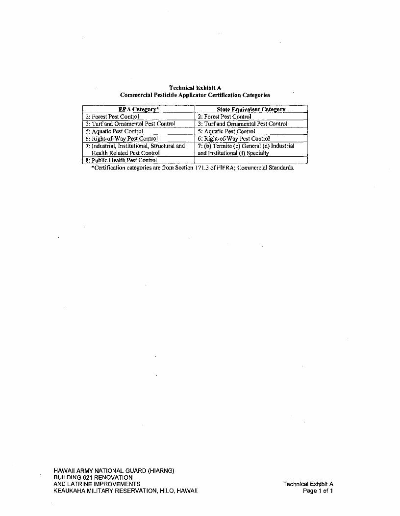
Technical Exhibit A Commercial Pesticide Applicator Certification Categories
EPA Category* State Equivalent Category 2: Forest Pest Control 2: Forest Pest Control 3: Turf and Ornamental Pest Control 3: Turf and Ornamental Pest Control 5: Aquatic Pest Control 5: Aquatic Pest Control 6: Right-of-Way Pest Control 6: Right-of-Way Pest Control 7: Industrial, Institutional, Structural and
Health Related Pest Control 7: (b) Termite (c) General (d) Industrial and Institutional (f) Specialty
8: Public Health Pest Control *Certification categories are from Section 171.3 of FIFRA; Commercial Standards.
HAWAII ARMY NATIONAL GUARD (HIARNG) BUILDING 621 RENOVATION AND LATRINE IMPROVEMENTS
Technical Exhibit A
KEAUKAHA MILITARY RESERVATION, HILO, HAWAII
Page 1 of 1

Technical Exhibit B
HIARNG Approved Pesticides List
APPROVED PESTICIDE LIST FOR HIARNG - INSECTICIDES
IPMP - APPENDIX M U dated: 3 Much 2011
L
4 1) EJ 1 3 1 1)
rI is
Award Fire Ant Bait 100-990 Demon tEl/P cyperrrathrin 40.0 Warning 100-1066 Demand CS lambda-cyhalothrin 9.7 Caution 100-1240 Demand G lambda-cyhaiothrin 0.045 Caution 100-1260 Optigard Mt Gel thlarnethoxam 0.01 Caution 241-392 Phantom Terrnticide-insecticide chlorfenapyr 21.45 Caution 279-3168 Talstar EZ Granular bifenthnn 0.2 Caution 279-3168 Talstar PL Granular blfenthrrn 0.2 Caution 279-3206 Talstar P Professional blienthrin 7.9 Caution 352-652 Mvlon Cockroach Gel indoxacarb 0.6 Caution 352-746 Aevion Mt Gel Indoxacrab (oxadiazlne) 0.05 Caution 432-716 Scourge resmathnn 4.14 Caution Yes
piperonyl Butoxide Technical 12.42 432-763 Suspend SC deltanathnn 4.75 Caution 432-772 Delta Dust deltamathrin 0.05 Caution 432-1226 Sevin 80 WSP carbaryt 80.0 Warning 432-1256 Maxtorce FC Mt Bait fipronil 0.01 Caution 432-1259 Maxtorce FC Roach Killer Bait Gel (24-60 gram) flpronil 0.01 Caution 432-1262 Maxtorce FG hydramethylnon 1.0 Caution 432-1264 Maxforce FC Mt Bait Gel fipronhl 0.001 Caution 432-1328 Merit 0.5 G inidadoprid 0.5 caution 432-1363 Tempo SC Ultra beta-cyfluthrin 11.8 Caution 432-1375 Maxforce Granular fly Bait inidacloprld 0.50 Caution 432-1377 Tempo Ultra WSP beta-cyfiuthrin 10.0 Caution 432-1455 Maiorce Fly Spot Bait inidacbprld 10.0 Caution 423-1483 Terrprid SC inidacloprld 21.0 Caution
cyfluthrin 10.5 498-116 Kill Zone House & Garden Insect Killer Formula 4 resmethrin 0.200 Caution
d-trans iJiethrin 0.125 499-290 PT 565 Plus XLO pyrethrin 0.5 Caution
piperonyl butoxide 1.0 N-octyt blcydoheptene dicarboxinide 1.0
499-294 Avert Dry Flowable Cockroach Bait abamectin 0.05 Caution 499-304 Cy-Kick CS cyfluthrin 6.0 Caution 499-362 Wasp-Freeze Wasp & Hornet Killer phenothnn 0.120 Caution
allethrin 0.129 499-370 Advance Granular Mt Bait abamectin 0.011 Caution 499-384 Perma-Dust boric add 35.50 Caution 499-450 ULD BP-300 •yrethrins 3.00 Caution
piperonyl Butoxide 6.0 N-octyl bicyctoheptene diarbmdnide 10.0
499-467 Avert Cockroach Bait Stations Formula I abamectin 0.05 Caution 499-470 PT Crack & Crevice I Cyfluthrin cyfluthnn 0.1 Caution 499-473 PT 221L Residual lambda-cyhalothrin 0.05 Caution 499-496 Advance 360A Dual Choice Mt Bait Stations abamectin 0.011 Caution 499-501 PT 250 Propmar propoxur 1.0 Caution 655-777 Prentox Malathion (1 gal) malathion 57.00 Warning 1475-1 Enoz Moth Ice Crystals paradich!orobenzene 99.6 Warning 1475-74 Enoz Old Fashioned Moth Balls naphthalene 99.9 Warning 2724-274 Starbar Golden Makin Fly Bait S rrathomyt 1.149 Caution 2724-351 Zoecon Gentrol IGR Concentrate hydroprene 9.0 Caution 2724-421 Zoecon Altosid XR Extended Residual Briquets methoprene 2.1 Caution 2724446 Zoecon AJtosid LIquid Larvicide Conc. methoprene 20.0 Caution 2724-448 Zoecon ftjtosid Pellets Mosquito Growth Regulator methoprene 4.25 Caution 2724450 Zoecon Catalyst Emulsified in Water Insectiade propetamphos 18.9 Warning 2724-461 Starbar Quik Strike Fly Abatement Strip nithlazine 1.0 Caution 2724-469 Gentrol Point Source Roach Control Device hydroprene 90.6 Caution 2724-484 Gentrol Aerosol hydroprene 0.36 2724-490 Precor 2000 Plus Premise Spray methoprene 0.085 Caution
permethrin 0.350 phenothrin 0.300 piperonyl butoxide technical 2.0
HAWAII ARMY NATIONAL GUARD (HIARNG) BUILDING 621 RENOVATION AND LATRINE IMPROVEMENTS
Technical Exhibit B
KEAUKAHA MILITARY RESERVATION, HILO, HAWAII
Page 1 of 4

APPROVED PESTICIDE LIST
IPMP - APPENDIX M
FOR H1ARNG - INSECTICIDES
U. dated: 3 March 2011
A
2724-791
1
[lit lii .0 ir
... a RAF-
ZenivexE20 etofen.rox 20.0 Caution 4822-271 Raid Was. and Hornet KIller 271 tetramethrin 0.2 Caution
ermethnn 0.2 5481480 Dibrom naled 87.4 Dan.er Yes 5481-520 Wisdom TC Flowable bifenthrin 7.9 Caution 6218-47 Sumrnt B.tJ. Bn.uets bacillus thurin.iensls 10.31 Caution 7969-209 Ternldor 80WG 5. ronil 80.0 Warnln' 7969-210 Ternldor SC 5. ronhl 9.1 Caution 9444-182 ftjr-Devil HPX .ermethnn 0.10 Caution 9444-217 D-Force HPX Residual dellamethnn 0.06 Caution 9688-217-8845 I73V indoxacarb 0.016 Caution 33657-16-59639 SafarI 20 50 dinotefuran 20.0 Caution 45385-97-56 Kills Bedbus S II deltamethrin 0.03 Caution 46515-48-9688 House & Garden Bu! Killer •ermethnn 0.15 Caution
d-trans ,AJlethrin 0.25 53263-28 A! nl'ue MMF .oI 100.0 Caution 53883-70 Surrender Peslabs lambda- halothnn 10.0 IiLiT - 59639-91 Orthene ace .hate 97.4 Caution 62719-291 Conserve SC s.inosad 11.6 64240-33 Combat Quick Kill Re, ular Size fl.ronil 0.03 Caution 64240-34 Combat Quick Kill La reSize fi.rorril 0.03 Caution 67760-34 F anon ULV 54 al drum malathion 96.5 Caution 72959-4 Phosto,an 100 tablets aluminum .hos'hlde 55.0 Dan.er Yes 72959-1-5857 Furmtoxin 100 tablets aluminum .hos. Ide 55.0 Dan.er Yes 73049-56 VectoBac WDG bacillus thurin ' lensls 37.4 Caution 73342-1 Arndro Fire Ant Bait h drameth Inon 0.73 Caution 73748-7 Masterline bifenthnn 7.9 Caution
HAWAII ARMY NATIONAL GUARD (HIARNG) BUILDING 621 RENOVATION AND LATRINE IMPROVEMENTS
Technical Exhibit B
KEAUKAHA MILITARY RESERVATION, HILO, HAWAII
Page 2 of 4

APPROVED PESTICIDE LIST FOR HIARNG - HERBICI DES/FU NGICI DESFALGACIDES
IPMP -APPENDIX M Updated: 3 March 2011
Tl ill I kf, 0
-& it
if ii (f I i i
t
I 1 .
FUNGICIDES
100-1093 Heritage Azoxystrobin 50.00 Caution 69850-1-75341 Osrnose MITC-FUME Methylisothlocyanate 97.00 Danger Yes 75341-11 COP-R-NAP Copper naphthenate 68.00 Warning -
HERBICIDES
100-1084 Fusilade II fluazifop-p-butyl 24.5 Caution 100-1091 Reward dlquat dibrorride 37.3 Caution 100-1121 Touchdown Pro glyphosate 28.3 Caution 228-139 24-D L.V. 4 Ester isooctyl 67.2 Danger 228-145 WEEDestroy AM-40 dirnethylarrine salt of 2,4-D 47.3 Danger 228-366 Razor PRO (2.5 gal) glyphosate 41.0 Caution 241-365 Plateau irnazapic 23.6 Caution 241-426 Habitat irnazapyr 28.7 Caution 241-431 Arsenal Power Line irnazapyr 26.7 Caution 352-287 Hyvar X brornacil 80.0 Caution Yes 352-346 HyvarX-L brornacil 21.9 Caution Yes 352-505 Krovar I DF brormcii 40.0 Caution Yes
diruon 40.0 352-601 Oust XP sulforneturon rnethyl 75.0 Caution 352-692 Kamm DF Diuron 80.0 Caution 432-886 Ronstar G oxadlazon 2.0 Warning 524-343 Aquarnaster gyphosate 53.8 Caution 524-475 Roundup Pro glyphosate 41.0 Caution 524-517 Ranger Pro glyphosate 41.0 Caution 524-535 QuIk Pro glyphosate 73.3 Caution -
dlquat dibrorrode 2.9 524-537 Round Up Weather Max glyphosate 48.8 Caution 524-579 Round Up Pro Max glyphosate 48.7 Caution 2217-833 Speed Zone carfentrazone-ethyl 0.62 Caution
2,4-D, 2-ethylhexyl ester 28.57 rnecoprop-p acid 5.88 dicanta acid 1.71
2217-834 Power Zone carfentrazone-ethyl 0.48 Caution MCPA 2-ethylhexyl ester 41.98 rmcoprop-p acid 5.39 dicanta acid 2.69
34704-648 Diuron 80 WDG diuron 80.0 Caution 6271937 Garlon 3A trlclo!yr 44.4 Danger 62719-40 Garlon 4 trldopyr 61.6 Caution 62719-324 Rodeo glyphosate 53.8 Caution 62719-527 Garlon 4 Ultra tridopyr 60.45 Caution 62719-537 Milestone W Aninopyralid - 40.6 Caution 66222-22-34704 Pramitol 25E prormton 25.0 Danger 67690-3 Sonar SRP fluridone 5.0 Caution 67690-4 Sonar AS. flundone 41.7 Caution 70506-44 Surfian AS oryzalin 40.4 Caution 71995-26 Round Up Weed & Grass Conc glyphosate 25.0 Caution
HAWAII ARMY NATIONAL GUARD (HIARNG) BUILDING 621 RENOVATION AND LATRINE IMPROVEMENTS
Technical Exhibit B
KEAUKAHA MILITARY RESERVATION, HILO, HAWAII
Page 3 of 4
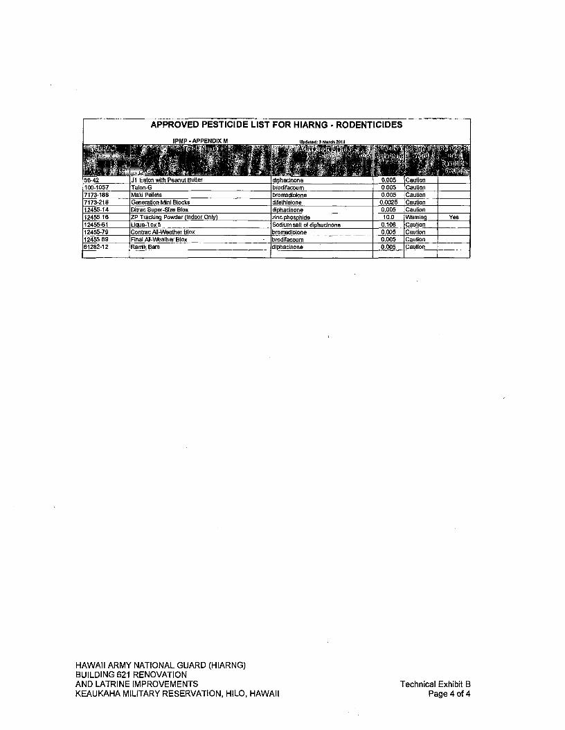
APPROVED PESTICIDE LIST FOR HIARNG RODENTICIDES
HAWAII ARMY NATIONAL GUARD (HIARNG) BUILDING 621 RENOVATION AND LATRINE IMPROVEMENTS
Technical Exhibit B
KEAUKAHA MILITARY RESERVATION, HILO, HAWAII
Page 4 of 4

If Pesticide is Used Applicator
Initials Ca Target Contro. Pest Operatton Maine
Unit of Measore
Work .Ongn
Labor Time
Uiüls s€: EPA Reg Amount
C
BUILDING(AREA TYPE OF CONSTRUCTION
USE DESK3NATION SIZE
DO Fern) 1532-1 . PEST ME MA!NTENANCE RECORD.
Technical Exhibit C
DD Form 1532-1
MEASUREMENT UNITS MSF= 1.000squarefeet MCF = 10(X) cubic feet LFF = Linear feet AC Acres
ORIGIN (W WOHI( SW = Scheduled woft WR = Work request SC = Service or trouble call R = Routine aispedton
TYPE OF CONSTRUCTiON CO = Concrete WO Weed 0L0(ock OT= Other
&ick veneer ST = Steal, sheet niet
HAWAII ARMY NATIONAL GUARD (HIARNG) BUILDING 621 R,NOVATION AND LATRINE IMPROVEMENTS
Technical Exhibit C
KEAUKAHA MILITARY RESERVATION, H1LO, HAWAII
Page 1 of 1

SECTION 02530 - SEWER SYSTEM
PART 1 - GENERAL
1.01 SUMMARY A. This section includes but is not limited to the following for sewer systems:
1. Pipe and fittings.
2. Non-pressure couplings.
3. Cleanouts.
4. Encasement for piping.
5. Manholes.
B. Related Work Described Elsewhere: 1. Earthwork for the sewer system is specified in SECTION 02300 -
EARTHWORK. Sewer system trenching, bedding, and backfilling requirements.
1.02 SUBMITTALS A. Submit in accordance with SECTION 01330 - SUBMITTAL PROCEDURES.
B. Product Certificates: For each type of pipe and fitting, from manufacturer.
C. Submit pipeline testing results.
D. Submit field quality-control reports.
1.03 DELIVERY, STORAGE, AND HANDLING A. Do not store plastic pipe and fittings in direct sunlight.
B. Protect pipe, pipefittings, and seals from dirt and damage.
C. Handle manholes according to manufacturer's written rigging instructions.
PART 2- PRODUCTS
2.01 PVC PIPE AND FITTINGS A. PVC Type PSM Sewer Piping:
1. Pipe: ASTM D 3034-16, SDR 35, PVC Type PSM sewer pipe with bell-and-spigot ends for gasketed joints.
2. Fittings: ASTM D 3034-16, PVC with bell ends.
3. Gaskets: ASTM F 477-14, elastomeric seals.
HAWAII ARMY NATIONAL GUARD (HIARNG) BUILDING 621 RENOVATION AND LATRINE IMPROVEMENTS
Sewer System
KEAUKAHA MILITARY RESERVATION, HILO, HAWAII
02530-1

2.02 NONPRESSURE-TYPE TRANSITION COUPLINGS A. Comply with ASTM C 1173-18, elastomeric, sleeve-type, reducing, or transition
coupling, for joining underground non-pressure piping. Include ends of same sizes as piping to be joined and corrosion-resistant-metal tension band and tightening mechanism on each end.
B. Sleeve Materials: 1. For Plastic Pipes: ASTM F 477-14, elastomeric seal or ASTM D 5926-15,
PVC.
2. For Dissimilar Pipes: ASTM D 5926-15, PVC or other material compatible with pipe materials being joined.
C. Unshielded, Flexible Couplings: 1. Description: Elastomeric sleeve with stainless-steel shear ring and corrosion-
resistant-metal tension band and tightening mechanism on each end.
D. Ring-Type, Flexible Couplings: Elastomeric compression seal with dimensions to fit inside bell of larger pipe and for spigot of smaller pipe to fit inside ring.
2.03 CLEANOUTS A. Cast-Iron Cleanouts: ASME Al 12.36.2M, round, gray-iron housing with clamping
device and round, secured, scoriated, gray-iron cover. Include gray-iron ferrule with inside calk or spigot connection and countersunk, tapered-thread, brass closure plug. 1. Top-Loading Classification(s): Extra-Heavy Duty.
2. Sewer Pipe Fitting and Riser to Cleanout: ASTM A 74-17, Service class, cast-iron soil pipe and fittings.
2.04 ENCASEMENT FOR PIPING A. Standard: ASTM A 674-18 or AWWA Cl 05.
B. Material: Linear low-density polyethylene film of 0.008-inch or high-density, cross-laminated polyethylene film of 0.004-inch minimum thickness.
C. Form: Sheet or tube.
D. Color: Black or natural.
PART 3- EXECUTION
3.01 EARTHWORK A. Excavating, trenching, and backfilling are specified in SECTION 02300 -
EARTHWORK
HAWAII ARMY NATIONAL GUARD (HIARNG) BUILDING 621 RENOVATION AND LATRINE IMPROVEMENTS
Sewer System
KEAUKAHA MILITARY RESERVATION, HILO, HAWAII
02530-2

3.02 PIPING INSTALLATION A. General Locations and Arrangements: Drawings indicate general location and
arrangement of underground sanitary sewer piping. Location and arrangement of piping layout take into account design considerations. Install piping as indicated. Where specific installation is not indicated, follow piping manufacturer's written instructions.
B. Install piping beginning at low point, true to grades and alignment indicated with unbroken continuity of slope. Place bell ends of piping facing upstream. Install gaskets, seals, sleeves, and couplings according to manufacturer's written instructions.
C. Install manholes for changes in direction unless fittings are indicated.
D. Install proper size increasers, reducers, and couplings where different sizes or materials of pipes and fittings are connected. Reducing size of piping in direction of flow is prohibited.
E. Install gravity-flow, non-pressure, sewer piping according to the following: 1. Install piping pitched down in direction of flow, at minimum slope of 2.08
percent unless otherwise indicated.
2. Install piping NPS 6 and larger with restrained joints at tee fittings and at changes in direction. Use corrosion-resistant rods, pipe or fitting manufacturer's proprietary restraint system, or cast-in-place-concrete supports or anchors.
3. Install piping with 36-inches minimum cover in sidewalk areas or areas not subject to vehicular loads and 48-inches minimum cover in paved areas or areas that may be subject to vehicular loads.
4. Install PVC Type PSM sewer piping according to ASTM D 2321-18 and ASTM F 1668-16.
F. Install corrosion-protection piping encasement over the following underground metal piping according to ASTM A 674-10(2014) or AWWA Cl 05: 1. Hubless cast-iron soil pipe and fittings.
G. Clear interior of piping and manholes of dirt and superfluous material as work progresses. Maintain swab or drag in piping and pull past each joint as it is completed. Place plug in end of incomplete piping at end of day and when work stops.
3.03 PIPE JOINT CONSTRUCTION A. Join gravity-flow, non-pressure, sewer piping according to the following:
1. Join hubless cast-iron soil piping according to CISPI 310 and CISPI's "Cast Iron Soil Pipe and Fittings Handbook" for hubless-coupling joints.
2. Join PVC Type PSM sewer piping according to ASTM D 2321-18 and ASTM D 3034-16 for elastomeric-seal joints and elastomeric-gasket joints.
3. Join PVC, AWWA C900 sewer pipe according to AWWA M23. HAWAII ARMY NATIONAL GUARD (HIARNG) BUILDING 621 RENOVATION AND LATRINE IMPROVEMENTS KEAUKAHA MILITARY RESERVATION, HILO, HAWAII
Sewer System 02530-3

4. Join dissimilar pipe materials with non-pressure-type, flexible or rigid couplings.
B. Pipe couplings with pressure ratings at least equal to piping rating may be used in applications below unless otherwise indicated. 1. Use non-pressure flexible couplings where required to join gravity-flow, non-
pressure sewer piping unless otherwise indicated. a. Unshielded flexible couplings for pipes of same or slightly different OD.
b. Unshielded, increaser/reducer-pattern, flexible couplings for pipes with different OD.
c. Ring-type flexible couplings for piping of different sizes where annular space between smaller pipings OD and larger piping's ID permits installation.
3.04 CLEANOUT INSTALLATION A. Install cleanouts and riser extensions from sewer pipes to cleanouts at grade.
Use cast-iron soil pipe fittings in sewer pipes at branches for cleanouts and use cast-iron soil pipe for riser extensions to cleanouts. Install piping so cleanouts open in direction of flow in sewer pipe.
B. Set cleanout frames and covers in earth in cast-in-place-concrete block, eighteen by eighteen (18 by 18) by twelve (12) inches deep. Set with tops one (1) inch above surrounding grade.
C. Set cleanout frames and covers in concrete pavement and roads with tops flush with pavement surface.
3.05 CONNECTIONS A. Connect non-pressure, gravity-flow sewer piping to existing sewer system as
indicated.
B. Make connections to existing piping. 1. Remove existing cleanout, install new in-line cleanout.
2. Protect existing piping and manholes to prevent concrete or debris from entering while making tap connections. Remove debris or other extraneous material that may accumulate.
3.06 IDENTIFICATION A. Materials and their installation are specified in SECTION 02300 - EARTHWORK.
Arrange for installation of green warning tapes directly over piping and at outside edges of underground manholes. 1. Use detectable warning tape over nonferrous piping and over edges of
underground manholes
3.07 FIELD QUALITY CONTROL A. Inspect interior of piping to determine whether line displacement or other damage
has occurred. Inspect after approximately twenty-four (24) inches of backfill is in place, and again at completion of project. 1. Submit separate report for each system inspection.
HAWAII ARMY NATIONAL GUARD (HIARNG) BUILDING 621 RENOVATION AND LATRINE IMPROVEMENTS
Sewer System
KEAUKAHA MILITARY RESERVATION, HILO, HAWAII
02530-4
2. Defects requiring correction include the following: a. Alignment: Less than full diameter of inside of pipe is visible between
structures.
b. Damage: Crushed, broken, cracked, or otherwise damaged piping.
c. Infiltration: Water leakage into piping.
d. Exfiltration: Water leakage from or around piping.
3. Replace defective piping using new materials, and repeat inspections until defects are within allowances specified.
4. Reinspect and repeat procedure until results are satisfactory.
B. Test new piping systems, and parts of existing systems that have been altered, extended, or repaired, for leaks and defects. 1. Notify the Project Manager at least seven (7) days prior to installing pipes.
2. Do not enclose, cover, or put into service before inspection and acceptance.
3. Test completed piping systems according to requirements of the Project Manager.
4. Schedule tests and inspections by the Project Manager with at least 72 hours advance notice.
5. Submit separate report for each test.
6. Hydrostatic Tests: Test sanitary sewerage according to requirements of the Project Manager and the following: a. Fill sewer piping with water. Test with pressure of at least ten (10) feet
head of water and maintain such pressure without leakage for at least fifteen (15) minutes.
b. Close openings in system and fill with water.
c. Purge air and refill with water.
d. Disconnect water supply.
e. Test and inspect joints for leaks.
7. Air Tests: Test sanitary sewerage according to requirements of the Project Manager, UNI-13-6, and the following: a. Test plastic gravity sewer piping according to ASTM F 1417-11A(2015).
C. Leaks and loss in test pressure constitute defects that must be repaired.
D. Replace leaking piping using new materials, and repeat testing until leakage is within allowances specified.
HAWAII ARMY NATIONAL GUARD (HIARNG) BUILDING 621 RENOVATION AND LATRINE IMPROVEMENTS
Sewer System
KEAUKAHA MILITARY RESERVATION, HILO, HAWAII
02530-5

3.08 CLEANING A. Clean dirt and superfluous material from interior of piping.
END OF SECTION
HAWAII ARMY NATIONAL GUARD (HIARNG) BUILDING 621 RENOVATION AND LATRINE IMPROVEMENTS
Sewer System
KEAUKAHA MILITARY RESERVATION, HILO, HAWAII
02530-6
SECTION 02600 - DRAINAGE SYSTEM
PART 1 - GENERAL
1.01 SUMMARY A. This section includes but is not limited to the following for drainage system:
1. PVC pipe and fittings.
2. Seepage wells.
B. Related Work Described Elsewhere: 1. Earthwork for the drainage system is specified in SECTION 02300 -
EARTHWORK. Drainage system trenching and backfilling requirements.
1.02 SUBMITTALS A. Submit in accordance with SECTION 01330 - SUBMITTAL PROCEDURES.
B. Shop Drawings: For seepage wells. Include plans, elevations, sections, details, frames, covers, and grates.
C. Product Certificates: For each type of pipe and fitting, from manufacturer.
D. Submit field quality-control reports.
1.03 DELIVERY, STORAGE, AND HANDLING A. Do not store plastic pipe, and fittings in direct sunlight.
B. Protect pipe, pipefittings, and seals from dirt and damage.
C. Handle seepage wells according to manufacturer's written rigging instructions.
PART 2- PRODUCTS
2.01 PVC PIPE AND FITTINGS A. PVC Corrugated Sewer Piping:
1. Pipe: ASTM F 949, PVC, corrugated pipe with bell-and-spigot ends for gasketed joints.
2. Fittings: ASTM F 949, PVC molded or fabricated, socket type.
3. Gaskets: ASTM F 477, elastomeric seals.
B. PVC Profile Sewer Piping: 1. Pipe: ASTM F 794, PVC profile, gravity sewer pipe with bell-and-spigot ends
for gasketed joints.
2. Fittings: ASTM D 3034, PVC with bell ends.
3. Gaskets: ASTM F 477, elastomeric seals.
HAWAII ARMY NATIONAL GUARD (HIARNG) BUILDING 621 RENOVATION AND LATRINE IMPROVEMENTS
Drainage System
KEAUKAHA MILITARY RESERVATION, HILO, HAWAII
02600-1

2.02 SEEPAGE WELLS A. Description: ASTM C 913-18, precast, reinforced, perforated concrete rings.
Include the following: 1. Floor: Crushed rock, nominal size range of 1-1/2 to 2-1/2 inches.
2. Cover: Liftoff-type concrete cover with cast-in lift rings.
3. Wall Thickness: 4-1/2 inches minimum with 1-1/2 by 3-inch and 1-3/4 by 4-inch diameter or 2-1/2 by 8-inch-maximum slotted perforations arranged in rows parallel to axis of ring.
4. Crushed Rock: 1-1/2 to 2-1/2 inches washed.
5. Depth: 6-feet ring section.
6. Grate: 1-1/2 inch thick fiberglass reinforced plastic with 1-inch rungs, 3/8 to 1/2 inch slots. Color: Black.
7. Grate Frame: ASTM A 48/A 48M-03 Class 35 gray iron unless otherwise indicated.
PART 3- EXECUTION
3.01 EARTHWORK A. Excavation, trenching, and backfilling are specified in SECTION 02300 -
EARTHWORK.
3.02 PIPING INSTALLATION A. General Locations and Arrangements: Drawing plans and details indicate
general location and arrangement of underground storm drainage piping. Location and arrangement of piping layout take into account design considerations. Install piping as indicated, to extent practical. Where specific installation is not indicated, follow piping manufacturer's written instructions.
B. Install piping beginning at low point, true to grades and alignment indicated with unbroken continuity of invert. Place bell ends of piping facing upstream. Install gaskets, seals, sleeves, and couplings according to manufacturer's written instructions for use of lubricants, cements, and other installation requirements.
3.03 SEEPAGE WELL INSTALLATION A. Excavate hole to diameter twelve (12) inches minimum greater than outside of
concrete ring. Do not extend excavation into ground-water table.
B. Place crushed rock in the bottom of excavation and level to provide a solid base for the precast concrete-rings.
C. Install precast, concrete-ring seepage wells according to the following: 1. Assemble rings to depth indicated.
2. Extend rings to height where top of cover will be at finished grade indicated.
HAWAII ARMY NATIONAL GUARD (HIARNG) BUILDING 621 RENOVATION AND LATRINE IMPROVEMENTS
Drainage System
KEAUKAHA MILITARY RESERVATION, HILO, HAWAII
02600-2

3. Backf ill bottom of inside of rings with crushed rock material to level at least twelve (12) inches above bottom.
4. Extend drainpipe twelve (12) inches into rings, where shown.
5. Backf ill around outside of rings with filtering material to top level of rings.
6. Install cover over top of rings.
3.04 CLEANING A. Clean interior of seepage well of dirt and superfluous materials.
END OF SECTION
HAWAII ARMY NATIONAL GUARD (HIARNG) BUILDING 621 RENOVATION AND LATRINE IMPROVEMENTS
Drainage System
KEAUKAHA MILITARY RESERVATION, HILO, HAWAII
02600-3
SECTION 02740 - ASPHALT CONCRETE PAVING
PART 1 - GENERAL
1.01 SUMMARY A. This section includes the following for asphalt concrete paving:
1. Hot-mix asphalt patching.
2. Hot-mix asphalt paving.
3. Pavement-marking paint.
4. Wheel Stops.
B. Related Work Described Elsewhere: 1. SECTION 02220 - SITE DEMOLITION for demolition, removal, and recycling
of existing asphalt pavements, and for geotextiles that are not embedded within courses of asphalt paving.
2. SECTION 02300 - EARTHWORK for aggregate base course for concrete walks and pavements, and asphalt paving.
1.02 DEFINITION A. Hot-Mix Asphalt Paving Terminology: Refer to ASTM D 8-19 for definitions of
terms.
1.03 SUBMITTALS A. Submit in accordance with SECTION 01330 - SUBMITTAL PROCEDURES.
B. Product Data: For each type of product indicated. Include technical data and tested physical and performance properties. 1. Job-Mix Designs: Certification of each job mix proposed.
C. Shop Drawings: Indicate pavement markings, lane separations, and defined parking spaces. Indicate, with international symbol of accessibility, spaces allocated for people with disabilities.
D. Qualification Data: For qualified manufacturer and installer.
E. Material Certificates: For each paving material, from manufacturer.
F. Material Test Reports: For each paving material.
G. Field Observations and Test Results: All test results and field logs from the Contractor's testing firm are to be submitted to the Project Manager at the end of each day's work.
HAWAII ARMY NATIONAL GUARD (HIARNG) BUILDING 621 RENOVATION AND LATRINE IMPROVEMENTS
Asphalt Concrete Paving
KEAUKAHA MILITARY RESERVATION, HILO, HAWAII
02740-1
1.04 QUALITY ASSURANCE A. Manufacturer Qualifications: A paving-mix manufacturer registered with and
approved by authorities having jurisdiction or the State of Hawaii Department of Transportation (DOT).
B. Testing Agency Qualifications: Qualified according to ASTM D 3666-16 for testing indicated.
C. Regulatory Requirements: Comply with materials, workmanship, and other applicable requirements of State of Hawaii DOT for asphalt paving work. 1. Measurement and payment provisions and safety program submittals
included in standard specifications do not apply to this section.
D. Preinstallation Conference: Conduct conference at project site. 1. Review methods and procedures related to hot-mix asphalt paving including,
but not limited to, the following: a. Review proposed sources of paving materials, including capabilities and
location of plant that will manufacture hot-mix asphalt.
b. Review condition of subgrade and preparatory work.
c. Review requirements for protecting paving work, including restriction of traffic during installation period and for remainder of construction period.
d. Review and finalize construction schedule and verify availability of materials, Installer's personnel, equipment, and facilities needed to make progress and avoid delays.
1.05 DELIVERY, STORAGE, AND HANDLING A. Deliver pavement-marking materials to the project site in original packages with
seals unbroken and bearing manufacturer's labels containing brand name and type of material, date of manufacture, and directions for storage.
B. Store pavement-marking materials in a clean, dry, protected location within temperature range required by manufacturer. Protect stored materials from direct sunlight.
1.06 PROJECT CONDITIONS A. Environmental Limitations: Do not apply asphalt materials if subgrade is wet or
excessively damp, if rain is imminent or expected before time required for adequate cure.
B. Pavement-Marking Paint: Proceed with pavement marking only on clean, dry surfaces and at a minimum ambient or surface temperature of 55 degrees F for water-based materials, and not exceeding 95 degrees F.
HAWAII ARMY NATIONAL GUARD (HIARNG) BUILDING 621 RENOVATION AND LATRINE IMPROVEMENTS
Asphalt Concrete Paving
KEAUKAHA MILITARY RESERVATION, HILO, HAWAII
02740-2

PART 2- PRODUCTS
2.01 AGGREGATES A. General: Use materials and gradations that have performed satisfactorily in
previous installations.
B. Coarse Aggregate: ASTM D 692/D 692M-1 5, sound; angular crushed stone, crushed gravel, or cured, crushed blast-furnace slag.
C. Fine Aggregate: ASTM D 1073-16 or AASHTO M 29, sharp-edged natural sand or sand prepared from stone, gravel, cured blast-furnace slag, or combinations thereof. 1. For hot-mix asphalt, limit natural sand to a maximum of twenty (20) percent
by weight of the total aggregate mass.
D. Mineral Filler: ASTM D 242/D 242M-19 or AASHTO M 17, rock or slag dust, hydraulic cement, or other inert material.
2.02 ASPHALT MATERIALS A. Asphalt Binder: AASHTO M 320, PG 64-16.
B. Asphalt Cement: Performance-graded asphalt binder shall conform to AASHTO M 320.
C. Prime Coat: Asphalt emulsion prime coat complying with State of Hawaii DOT requirements.
D. Tack Coat: Emulsified asphalt (Type SS-1, SS-1h, CSS-1 or CSS-1 h).
E. Water: Potable.
F. Undersealing Asphalt: ASTM D 3141/D 3141M-15, pumping consistency.
2.03 AUXILIARY MATERIALS A. Herbicide: Commercial chemical for weed control, registered by the EPA.
Provide in granular, liquid, or wettable powder form.
B. Sand: ASTM D 1073-16 or AASHTO M 29, Grade Nos. 2 or 3.
C. Pavement-Marking Paint: Reflectorized traffic paint shall conform to the requirements of Premixed Reflectorized White and Yellow Traffic Paint.
D. Wheel Stops: Precast, air-entrained concrete, 2500-psi minimum compressive strength, five (5) inches high by nine (9) inches wide by seventy-two (72) inches long. Provide chamfered corners, drainage slots on underside, and holes for anchoring to substrate. 1. Dowels: Galvanized steel, 1-inch diameter, 10-inch minimum length.
HAWAII ARMY NATIONAL GUARD (HIARNG) BUILDING 621 RENOVATION AND LATRINE IMPROVEMENTS
Asphalt Concrete Paving
KEAUKAHA MILITARY RESERVATION, HILO, HAWAII
02740 - 3
2.04 MIXES A. Hot-Mix Asphalt: Dense, hot-laid, hot-mix asphalt plant State DOT Mix V and
designed according to procedures in Al MS-2, Mix Design Methods for Asphalt Concrete and Other Hot-Mix Types.
PART 3- EXECUTION
3.01 EXAMINATION A. Verify that subgrade is dry and in suitable condition to begin paving.
B. Proof-roll subgrade below pavements with heavy pneumatic-tired equipment to identify soft pockets and areas of excess yielding. Do not proof-roll wet or saturated subgrades. 1. Completely proof-roll subgrade in one direction, repeating proof-rolling in
direction perpendicular to first direction. Limit vehicle speed to three (3) mph.
2. Proof roll with a loaded ten (10) wheel, tandem-axle dump truck weighing not less than fifteen (15) tons.
3. Excavate soft spots, unsatisfactory soils, and areas of excessive pumping or rutting, as determined by the Geotechnical Engineer, and replace with compacted backfill or fill as directed.
C. Proceed with paving only after unsatisfactory conditions have been corrected.
3.02 SURFACE PREPARATION A. General: Immediately before placing asphalt materials, remove loose and
deleterious material from substrate surfaces. Ensure that prepared subgrade is ready to receive paving.
B. Herbicide Treatment: Apply herbicide according to manufacturer's recommended rates and written application instructions. Apply to dry, prepared subgrade or surface of compacted-aggregate base before applying paving materials. 1. Mix herbicide with prime coat if formulated by manufacturer for that purpose.
C. Base Course: Install base course per SECTION 02300 - EARTHWORK.
D. Prime Coat: Apply uniformly over surface of compacted unbound-aggregate base course at a rate of 0.15 to 0.50 gallons per square yard. Apply enough material to penetrate and seal but not flood surface. Allow prime coat to cure. 1. If prime coat is not entirely absorbed within 24 hours after application, spread
sand over surface to blot excess asphalt. Use enough sand to prevent pickup under traffic. Remove loose sand by sweeping before pavement is placed and after volatiles have evaporated.
2. Protect primed substrate from damage until ready to receive paving.
E. Tack Coat: Apply uniformly to surfaces of existing pavement at a rate of 0.05 to 0.15 gallons per square yard. 1. Allow tack coat to cure undisturbed before applying hot-mix asphalt paving.
HAWAII ARMY NATIONAL GUARD (HIARNG) BUILDING 621 RENOVATION AND LATRINE IMPROVEMENTS
Asphalt Concrete Paving
KEAUKAHA MILITARY RESERVATION, HILO, HAWAII
02740-4

2. Avoid smearing or staining adjoining surfaces, appurtenances, and surroundings. Remove spillages and clean affected surfaces.
3.03 HOT-MIX ASPHALT PLACING A. Machine place hot-mix asphalt on prepared surface, spread uniformly, and strike
off. Place asphalt mix by hand to areas inaccessible to equipment in a manner that prevents segregation of mix. Place each course to required grade, cross section, and thickness when compacted. 1. Place hot-mix asphalt base course in number of lifts and thicknesses
indicated.
2. Place hot-mix asphalt surface course in single lift.
3. Spread mix at minimum temperature of two hundred fifty (250) degrees F.
4. Begin applying mix along centerline of crown for crowned sections and on high side of one-way slopes unless otherwise indicated.
5. Regulate paver machine speed to obtain smooth, continuous surface free of pulls and tears in asphalt-paving mat.
B. Place paving inconsecutive strips not less than ten (10) feet wide unless inf ill edge strips of a lesser width are required. 1. After first strip has been placed and rolled, place succeeding strips and
extend rolling to overlap previous strips. Complete a section of asphalt base course before placing asphalt surface course.
C. Promptly correct surface irregularities in paving course behind paver. Use suitable hand tools to remove excess material forming high spots. Fill depressions with hot-mix asphalt to prevent segregation of mix; use suitable hand tools to smooth surface.
3.04 JOINTS A. Construct joints to ensure a continuous bond with the adjoining paving sections.
Construct joints free of depressions, with same texture and smoothness as other sections of hot-mix asphalt course. 1. Clean contact surfaces and apply tack coat to joints.
2. Offset longitudinal joints, in successive courses, a minimum of six (6) inches.
3. Offset transverse joints, in successive courses, a minimum of twenty-four (24) inches.
4. Construct transverse joints at each point where paver ends at the end of each day and resumes work at a subsequent time. Construct these joints using either "bulkhead" or "papered" method according to Al MS-22, for both "Ending a Lane" and "Resumption of Paving Operations".
5. Compact joints as soon as hot-mix asphalt will bear roller weight without excessive displacement.
HAWAII ARMY NATIONAL GUARD (HIARNG) BUILDING 621 RENOVATION AND LATRINE IMPROVEMENTS
Asphalt Concrete Paving
KEAUKAHA MILITARY RESERVATION, HILO, HAWAII
02740 -5

6. Compact asphalt at joints to a density within two (2) percent of specified course density.
3.05 COMPACTION A. General: Begin compaction as soon as placed hot-mix paving will bear roller
weight without excessive displacement. Compact hot-mix paving with hot, hand tampers or with vibratory-plate compactors in areas inaccessible to rollers. 1. Complete compaction before mix temperature cools to one hundred eighty-
five (185) degrees F.
B. Breakdown Rolling: Complete breakdown or initial rolling immediately after rolling joints and outside edge. Examine surface immediately after breakdown rolling for indicated crown, grade, and smoothness. Correct laydown and rolling operations to comply with requirements.
C. Intermediate Rolling: Begin intermediate rolling immediately after breakdown rolling while hot-mix asphalt is still hot enough to achieve specified density. Continue rolling until hot-mix asphalt course has been uniformly compacted to the following density: 1. Average Density: ninety-six (96) percent of reference laboratory density
according to ASTM D 6927-15 or AASHTO T 245, but not less than ninety-four (94) percent nor greater than one hundred (100) percent.
2. Average Density: ninety-two (92) percent of reference maximum theoretical density according to ASTM D 2041/D 2041 M-1 9, but not less than ninety (90) percent nor greater than ninety-six (96) percent.
D. Finish Rolling: Finish roll paved surfaces to remove roller marks while hot-mix asphalt is still warm.
E. Edge Shaping: While surface is being compacted and finished, trim edges of pavement to proper alignment. Bevel edges while asphalt is still hot; compact thoroughly.
F. Repairs: Remove paved areas that are defective or contaminated with foreign materials and replace with fresh, hot-mix asphalt. Compact by rolling to specified density and surface smoothness.
G. Protection: After final rolling, do not permit vehicular traffic on pavement until it has cooled and hardened.
H. Erect barricades to protect paving from traffic until mixture has cooled enough not to become marked.
3.06 INSTALLATION TOLERANCES A. Pavement Thickness: Compact each course to produce the thickness indicated
within the following tolerances: 1. Base Course: Plus or minus 1/2 inch.
2. Surface Course: Plus 1/4 inch, no minus.
HAWAII ARMY NATIONAL GUARD (HIARNG) BUILDING 621 RENOVATION AND LATRINE IMPROVEMENTS
Asphalt Concrete Paving
KEAUKAHA MILITARY RESERVATION, HILO, HAWAII
02740-6

B. Pavement Surface Smoothness: Compact each course to produce a surface smoothness within the following tolerances as determined by using a ten- (10) foot straightedge applied transversely or longitudinally to paved areas: 1. Base Course: 1/4 inch.
2. Surface Course: 1/8 inch.
3. Crowned Surfaces: Test with crowned template centered and at right angle to crown. Maximum allowable variance from template is 1/4 inch.
3.07 PAVEMENT MARKING A. Do not apply pavement-marking paint until layout, colors, and placement have
been verified with the Project Manager.
B. Allow paving to age for thirty (30) days before starting pavement marking.
C. Sweep and clean surface to eliminate loose material and dust.
D. Apply paint with mechanical equipment to produce pavement markings, of dimensions indicated, with uniform, straight edges. Apply at manufacturer's recommended rates to provide a minimum wet film thickness of fifteen (15) mils.
3.08 WHEEL STOPS A. Install wheel stops in bed of adhesive as recommended by the manufacturer.
B. Securely attach wheel stops to pavement with not less than two galvanized-steel dowels embedded at one-quarter to one-third points as indicated. Securely install dowels into pavement and bond to wheel stop. Recess head of dowel beneath top of wheel stop and grout.
3.09 FIELD QUALITY CONTROL A. Testing Agency: Engage a qualified testing agency to perform tests and
inspections.
B. Thickness: In-place compacted thickness of hot-mix asphalt courses will be determined according to ASTM D 3549/D 3549M-1 8.
C. Surface Smoothness: Finished surface of each hot-mix asphalt course will be tested for compliance with smoothness tolerances.
D. In-Place Density: Testing agency will take samples of uncompacted paving mixtures and compacted pavement according to ASTM D 979/D 979M-1 5 or AASHTO T 168. 1. Reference maximum theoretical density will be determined by averaging
results from four samples of hot-mix asphalt-paving mixture delivered daily to site, prepared according to ASTM D 2041/D 2041 M-1 9, and compacted according to job-mix specifications.
2. In-place density of compacted pavement will be determined by testing core samples according to ASTM D 1188-07(2015) or ASTM D 2726/D 2726M-1 8.
HAWAII ARMY NATIONAL GUARD (HIARNG) BUILDING 621 RENOVATION AND LATRINE IMPROVEMENTS
Asphalt Concrete Paving
KEAUKAHA MILITARY RESERVATION, HILO, HAWAII
02740-7

a. One core sample will be taken for every 1,000 sq. yds. or less of installed pavement, with no fewer than one (1) core taken.
b. Field density of in-place compacted pavement may also be determined by nuclear method according to ASTM D 2950/D 2950M-14 and correlated with ASTM D 1188-07(2015) or ASTM D 2726/D 2726M-1 9.
E. Replace and compact hot-mix asphalt where core tests were taken.
F. Remove and replace or install additional hot-mix asphalt where test results or measurements indicate that it does not comply with specified requirements.
3.10 DISPOSAL A. Except for material indicated to be recycled, remove excavated materials from
project site, and legally dispose of them in State permitted landfill. 1. Do not allow milled materials to accumulate on-site.
END OF SECTION
HAWAII ARMY NATIONAL GUARD (HIARNG) BUILDING 621 RENOVATION AND LATRINE IMPROVEMENTS
Asphalt Concrete Paving
KEAUKAHA MILITARY RESERVATION, HILO, HAWAII
02740-8

SECTION 02750 - PORTLAND CEMENT
PART 1 - GENERAL
1.01 SUMMARY A. This section includes:
1. Walks.
2. Concrete Pads.
B. Related Work Described Elsewhere: 1. SECTION 02300 - EARTHWORK for aggregate base course for concrete
walks and pavements, and asphalt paving.
2. SECTION 03300 - CAST-IN-PLACE CONCRETE for general building applications of concrete.
1.02 DEFINITIONS A. Cementitious Materials: Portland cement alone or in combination with one or
more of blended hydraulic cement, fly ash and other pozzolans.
1.03 SUBMITTALS A. Submit in accordance with SECTION 01330 - SUBMITTAL PROCEDURES.
B. Product Data: For each type of product indicated.
C. Design Mixtures: For each concrete paving mixture. Include alternate design mixtures when characteristics of materials, Project conditions, weather, test results, or other circumstances warrant adjustments.
D. Qualification Data: For qualified ready-mix concrete manufacturer and testing agency.
E. Material Certificates: For the following, from manufacturer: 1. Cementitious materials.
2. Steel reinforcement and reinforcement accessories.
3. Admixtures.
4. Curing compounds.
5. Bonding agent or epoxy adhesive.
6. Joint fillers.
7. Silicone joint sealers.
F. Material Test Reports: For each of the following: 1. Aggregates.
HAWAII ARMY NATIONAL GUARD (HIARNG) BUILDING 621 RENOVATION AND LATRINE IMPROVEMENTS
Portland Cement
KEAUKAHA MILITARY RESERVATION, HILO, HAWAII
02750-1
G. Field quality-control reports.
1.04 QUALITY ASSURANCE A. Ready-Mix-Concrete Manufacturer Qualifications: A firm experienced in
manufacturing ready-mixed concrete products and that complies with ASTM C 94/C 94M-1 8 requirements for production facilities and equipment. 1. Manufacturer certified according to NRMCA's "Certification of Ready Mixed
Concrete Production Facilities", Quality Control Manual - Section 3, "Plant Certification Checklist".
B. Testing Agency Qualifications: Qualified according to ASTM C 1077-17 and ASTM E 329-18 for testing indicated. 1. Personnel conducting field tests shall be qualified as ACI Concrete Field
Testing Technician, Grade 1, according to ACI CP-1 or an equivalent certification program.
C. Concrete Testing Service: Engage a qualified testing agency to perform material evaluation tests and to design concrete mixtures.
D. ACI Publications: Comply with ACI 301 unless otherwise indicated.
1.05 PROJECT CONDITIONS A. Traffic Control: Maintain access for vehicular and pedestrian traffic as required
for other construction activities.
PART 2- PRODUCTS
2.01 FORMS A. Form Materials: Plywood, metal, metal-framed plywood, or other approved
panel-type materials to provide full-depth, continuous, straight, and smooth exposed surfaces.
B. Form-Release Agent: Commercially formulated form-release agent that will not bond with, stain, or adversely affect concrete surfaces and that will not impair subsequent treatments of concrete surfaces.
2.02 STEEL REINFORCEMENT A. Deformed Bar Reinforcement: ASTM A 615/A 615M-18e1, deformed grade 40
bars.
B. Wire Mesh Reinforcement: ASTM A 184/A 184M-17.
2.03 CONCRETE MATERIALS A. Cementitious Material: Use the following cementitious materials, of same type,
brand, and source throughout the project: 1. Portland Cement: ASTM C 150/C 150M-19a, Portland cement Type I/Il.
2. Fly Ash: ASTM C 618-19, Class F.
HAWAII ARMY NATIONAL GUARD (HIARNG) BUILDING 621 RENOVATION AND LATRINE IMPROVEMENTS
Portland Cement
KEAUKAHA MILITARY RESERVATION, HILO, HAWAII
02750-2

B. Normal-Weight Aggregates: ASTM C 33/C 33M-1 8, Class 1 N, uniformly graded. Provide aggregates from a single source. 1. Maximum Coarse-Aggregate Size: Walks and Curbs: 3/4 inch nominal.
Concrete Pad: One (1) inch nominal.
2. Fine Aggregate: Free of materials with deleterious reactivity to alkali in cement.
C. Water: Potable and complying with ASTM C 94/C 94M-18.
D. Air-Entraining Admixture: ASTM C 260/C260M-1 Oa(201 6).
E. Chemical Admixtures: Admixtures certified by manufacturer to be compatible with other admixtures and to contain not more than 0.1 percent water-soluble chloride ions by mass of cementitious material. 1. Water-Reducing Admixture: ASTM C 494/C 494M-1 7, Type A.
2. Retarding Admixture: ASTM C 494/C 494M-17, Type B.
3. Water-Reducing and Retarding Admixture: ASTM C 494/C 494M-17, Type D.
4. High-Range, Water-Reducing Admixture: ASTM C 494/C 494M-17, Type F.
5. High-Range, Water-Reducing and Retarding Admixture: ASTM C 494/C 494M-17, Type G.
6. Plasticizing and Retarding Admixture: ASTM C 1017/C1017M-13e1, Type II.
2.04 CURING MATERIALS A. Absorptive Cover: AASHTO M 182, Class 3, burlap cloth made from jute or
kenaf, weighing approximately nine (9) oz./sq. yd. dry or cotton mats.
B. Moisture-Retaining Cover: ASTM C 171-16, polyethylene film or white burlap-polyethylene sheet.
C. Water: Potable.
D. Evaporation Retarder: Waterborne, monomolecular, film forming, manufactured for application to fresh concrete.
E. Clear, Waterborne, Membrane-Forming Curing Compound: ASTM C 309-112 Type 1, Class B, dissipating.
F. White, Waterborne, Membrane-Forming Curing Compound: ASTM C 309-11, Type 2, Class B, dissipating.
2.05 RELATED MATERIALS A. Premolded Joint Filler: ASTM D 1752-18, Type I.
B. Silicone Joint Sealer: Federal Specification TT-S-001 543A and TT-S-00230C.
HAWAII ARMY NATIONAL GUARD (HIARNG) BUILDING 621 RENOVATION AND LATRINE IMPROVEMENTS
Portland Cement
KEAUKAHA MILITARY RESERVATION, HILO, HAWAII
02750-3

C. Bonding Agent: ASTM C 1059/C 1059M-13, Type II, non-redispersible, acrylic emulsion or styrene butadiene.
2.06 CONCRETE MIXTURES A. Prepare design mixtures, proportioned according to ACI 301, for each type and
strength of normal-weight concrete, and as determined by either laboratory trial mixtures or field experience. 1. Use a qualified independent testing agency for preparing and reporting
proposed concrete design mixtures for the trial batch method.
2. When automatic machine placement is used, determine design mixtures and obtain laboratory test results that meet or exceed requirements.
B. Proportion mixtures to provide normal-weight concrete with the following properties: 1. Compressive Strength at twenty-eight (28) Days: 4500 psi.
2. Maximum Water-Cementitious Materials Ratio at Point of Placement: 0.45.
C. Add air-entraining admixture at manufacturer's prescribed rate to result in normal-weight concrete at point of placement having an air content as follows: 1. Air Content: 3 percent plus or minus 1.5 percent for one (1) inch nominal
maximum aggregate size.
2. Air Content: 3-1/2 percent plus or minus 1.5 percent for 3/4 inch nominal maximum aggregate size.
D. Limit water-soluble, chloride-ion content in hardened concrete to 0.15 percent by weight of cement.
E. Chemical Admixtures: Use admixtures according to manufacturer's written instructions. 1. Use high-range, water-reducing and retarding admixture in concrete as
required for placement and workability.
2. Use water-reducing and retarding admixture when required by high temperatures, low humidity, or other adverse placement conditions.
F. Cementitious Materials: Limit percentage, by weight, of cementitious materials other than portland cement in concrete as follows: 1. Fly Ash or Pozzolan: Twenty-five (25) percent.
2.07 CONCRETE MIXING A. Ready-Mixed Concrete: Measure, batch, and mix concrete materials and
concrete according to ASTM C 94/C 94M-18. Furnish batch certificates for each batch discharged. 1. When air temperature is between eighty-five (85) and ninety (90) degrees F,
reduce mixing and delivery time from 1-1/2 hours to 75 minutes; when air temperature is above ninety (90) degrees F, reduce mixing and delivery time to sixty (60) minutes.
HAWAII ARMY NATIONAL GUARD (HIARNG) BUILDING 621 RENOVATION AND LATRINE IMPROVEMENTS
Portland Cement
KEAUKAHA MILITARY RESERVATION, HILO, HAWAII
02750-4

B. Project-Site Mixing: Measure, batch, and mix concrete materials and concrete according to ASTM C 94/C 94M-18. Mix concrete materials in appropriate drum-type batch machine mixer. 1. For concrete batches of one (1) cubic yard or smaller, continue mixing at
least 1-1/2 minutes, but not more than five (5) minutes after ingredients are in mixer, before any part of batch is released.
2. For concrete batches larger than 1 cubic yard, increase mixing time by fifteen (15) seconds for each additional cubic yard.
3. Provide batch ticket for each batch discharged, indicating the project identification name and number, date, mixture type, mixing time, quantity, and amount of water added.
PART 3- EXECUTION
3.01 EXAMINATION A. Examine exposed subgrades for compliance with requirements for dimensional,
grading, and elevation tolerances.
B. Proof-roll prepared subgrade surface below concrete paving to identify soft pockets and areas of excess yielding. 1. Completely proof-roll subbase in one direction and repeat in perpendicular
direction. Limit vehicle speed to three (3) mph.
2. Proof-roll with a pneumatic-tired and loaded, ten- (10) wheel, tandem-axle dump truck weighing not less than fifteen (15) tons.
3. Correct subbase with soft spots and areas of pumping or rutting exceeding depth of 1/2 inch according to requirements in SECTION 02300 - EARTHWORK
C. Proceed with installation only after unsatisfactory conditions have been corrected.
3.02 PREPARATION A. Remove loose material from compacted subgrade surface.
B. Base Course: Install base course per SECTION 02300 - EARTHWORK.
C. Remove loose material from compacted base course immediately before placing concrete.
3.03 EDGE FORMS AND SCREED CONSTRUCTION A. Set, brace, and secure edge forms, bulkheads, and intermediate screed guides
to required lines, grades, and elevations. Install forms to allow continuous progress of work and so forms can remain in place at least twenty-four 24 hours after concrete placement.
HAWAII ARMY NATIONAL GUARD (HIARNG) BUILDING 621 RENOVATION AND LATRINE IMPROVEMENTS
Portland Cement
KEAUKAHA MILITARY RESERVATION, HILO, HAWAII
02750-5

B. Clean forms after each use and coat with form-release agent to ensure separation from concrete without damage.
3.04 STEEL REINFORCEMENT A. General: Comply with CRSI's "Manual of Standard Practice" for fabricating,
placing, and supporting reinforcement.
B. Clean reinforcement of loose rust and mill scale, earth, ice, or other bond-reducing materials.
C. Arrange, space, and securely tie bars and bar supports to hold reinforcement in position during concrete placement. Maintain minimum cover to reinforcement.
D. Install welded wire reinforcement in lengths as long as practicable. Lap adjoining pieces at least one full mesh, and lace splices with wire. Offset laps of adjoining widths to prevent continuous laps in either direction.
E. Zinc-Coated Reinforcement: Use galvanized-steel wire ties to fasten zinc-coated reinforcement. Repair cut and damaged zinc coatings with zinc repair material.
F. Epoxy-Coated Reinforcement: Use epoxy-coated steel wire ties to fasten epoxy-coated reinforcement. Repair cut and damaged epoxy coatings with epoxy repair coating according to ASTM D 3963/D 3963M-1 5.
G. Install fabricated bar mats in lengths as long as practicable. Handle units to keep them flat and free of distortions. Straighten bends, kinks, and other irregularities, or replace units as required before placement. Set mats for a minimum two- (2) inch overlap of adjacent mats.
3.05 JOINTS A. General: Form construction, isolation, and contraction joints and tool edges true
to line, with faces perpendicular to surface plane of concrete. Construct transverse joints at right angles to centerline unless otherwise indicated. 1. When joining existing paving, place transverse joints to align with previously
placed joints unless otherwise indicated.
B. Construction Joints: Set construction joints at side and end terminations of paving and at locations where paving operations are stopped for more than one-half hour unless paving terminates at isolation joints. 1. Continue steel reinforcement across construction joints unless otherwise
indicated. Do not continue reinforcement through sides of paving strips unless otherwise indicated.
2. Provide tie bars at sides of paving strips where indicated.
3. Butt Joints: Use epoxy bonding adhesive at joint locations where fresh concrete is placed against hardened or partially hardened concrete surfaces.
4. Keyed Joints: Provide preformed keyway-section forms or bulkhead forms with keys unless otherwise indicated. Embed keys at least 1-1/2 inches into concrete.
HAWAII ARMY NATIONAL GUARD (HIARNG) BUILDING 621 RENOVATION AND LATRINE IMPROVEMENTS
Portland Cement
KEAUKAHA MILITARY RESERVATION, HILO, HAWAII
02750-6

5. Doweled Joints: Install dowel bars and support assemblies at joints where indicated. Lubricate or coat with asphalt one-half of dowel length to prevent concrete bonding to one side of joint.
C. Isolation Joints: Form isolation joints of preformed joint-filler strips abutting concrete curbs, catch basins, manholes, inlets, structures, other fixed objects, and where indicated. 1. Extend joint fillers full width and depth of joint.
2. Terminate joint filler not less than 1/2 inch or more than one (1) inch below finished surface if joint sealant is indicated.
3. Place top of joint filler flush with finished concrete surface if joint sealant is not indicated.
4. Furnish joint fillers in one-piece lengths. Where more than one length is required, lace or clip joint-filler sections together.
5. During concrete placement, protect top edge of joint filler with metal, plastic, or other temporary preformed cap. Remove protective cap after concrete has been placed on both sides of joint.
D. Contraction Joints: Form weakened-plane contraction joints, sectioning concrete into areas as indicated. Construct contraction joints for a depth equal to at least one-fourth of the concrete thickness, as follows: 1. Grooved Joints: Form contraction joints after initial floating by grooving and
finishing each edge of joint with grooving tool to a 1/4 inch radius. Repeat grooving of contraction joints after applying surface finishes. Eliminate grooving-tool marks on concrete surfaces. a. Tolerance: Ensure that grooved joints are within three (3) inches either
way from centers of dowels.
2. Sawed Joints: Form contraction joints with power saws equipped with shatterproof abrasive or diamond-rimmed blades. Cut 1/8-inch-wide joints into concrete when cutting action will not tear, abrade, or otherwise damage surface and before developing random contraction cracks. a. Tolerance: Ensure that sawed joints are within three (3) inches either
way from centers of dowels.
3. Doweled Contraction Joints: Install dowel bars and support assemblies at joints where indicated. Lubricate or coat with asphalt one-half of dowel length to prevent concrete bonding to one side of joint.
E. Edging: After initial floating, tool edges of paving, curbs, and joints in concrete with an edging tool to a 1/4-inch radius. Repeat tooling of edges after applying surface finishes. Eliminate edging-tool marks on concrete surfaces.
3.06 CONCRETE PLACEMENT A. Before placing concrete, inspect and complete formwork installation, steel
reinforcement, and items to be embedded or cast-in.
HAWAII ARMY NATIONAL GUARD (HIARNG) BUILDING 621 RENOVATION AND LATRINE IMPROVEMENTS
Portland Cement
KEAUKAHA MILITARY RESERVATION, HILO, HAWAII
02750-7
B. Moisten base course to provide a uniform dampened condition at time concrete is placed. Do not place concrete around manholes or other structures until they are at required finish elevation and alignment.
C. Comply with ACI 301 requirements for measuring, mixing, transporting, and placing concrete.
D. Do not add water to concrete during delivery or at the project site. Do not add water to fresh concrete after testing.
E. Deposit and spread concrete in a continuous operation between transverse joints. Do not push or drag concrete into place or use vibrators to move concrete into place.
F. Consolidate concrete according to ACI 301 by mechanical vibrating equipment supplemented by hand spading, rodding, or tamping. 1. Consolidate concrete along face of forms and adjacent to transverse joints
with an internal vibrator. Keep vibrator away from joint assemblies, reinforcement, or side forms. Use only square-faced shovels for hand spreading and consolidation. Consolidate with care to prevent dislocating reinforcement, dowels and joint devices.
G. Screed paving surface with a straightedge and strike off.
H. Commence initial floating using bull floats or darbies to impart an open-textured and uniform surface plane before excess moisture or bleed water appears on the surface. Do not further disturb concrete surfaces before beginning finishing operations or spreading surface treatments.
I. Hot-Weather Placement: Comply with ACI 301 and as follows when hot-weather conditions exist: 1. Cool ingredients before mixing to maintain concrete temperature below 90-
degree F at time of placement. Chilled mixing water or chopped ice may be used to control temperature, provided water equivalent of ice is calculated in total amount of mixing water. Using liquid nitrogen to cool concrete is Contractor's option.
2. Cover steel reinforcement with water-soaked burlap so steel temperature will not exceed ambient air temperature immediately before embedding in concrete.
3. Fog-spray forms, steel reinforcement, and subgrade just before placing concrete. Keep subgrade moisture uniform without standing water, soft spots, or dry areas.
3.07 FLOAT FINISHING A. General: Do not add water to concrete surfaces during finishing operations.
HAWAII ARMY NATIONAL GUARD (HIARNG) BUILDING 621 RENOVATION AND LATRINE IMPROVEMENTS
Portland Cement
KEAUKAHA MILITARY RESERVATION, HILO, HAWAII
02750-8
B. Float Finish: Begin the second floating operation when bleed-water sheen has disappeared, and concrete surface has stiffened sufficiently to permit operations. Float surface with power-driven floats or by hand floating if area is small or inaccessible to power units. Finish surfaces to true planes. Cut down high spots and fill low spots. Refloat surface immediately to uniform granular texture. 1. Burlap Finish: Drag a seamless strip of damp burlap across float-finished
concrete, perpendicular to line of traffic, to provide a uniform, gritty texture.
2. Medium-to-Coarse-Textured Broom Finish: Provide a coarse finish by drawing a stiff-bristled broom perpendicular to the line of traffic with adjacent strokes slightly overlapping to produce surface corrugations of uniform appearance 1/16 inch deep.
3.08 CONCRETE PROTECTION AND CURING A. General: Protect freshly placed concrete from premature drying and excessive
cold or hot temperatures.
B. Evaporation Retarder: Apply evaporation retarder to concrete surfaces if hot, dry, or windy conditions cause moisture loss. Apply according to manufacturer's written instructions after placing, screeding, and bull floating or darbying concrete but before float finishing.
C. Begin curing after finishing concrete but not before free water has disappeared from concrete surface.
D. Curing Methods: Cure concrete by moisture curing, moisture-retaining-cover curing, curing compound or a combination of these as follows: 1. Moisture Curing: Keep surfaces continuously moist for not less than seven
days with the following materials: a. Water.
b. Continuous water-fog spray.
c. Absorptive cover, water saturated and kept continuously wet. Cover concrete surfaces and edges with 12-inches lap over adjacent absorptive covers.
2. Moisture-Retaining-Cover Curing: Cover concrete surfaces with moisture-retaining cover, placed in widest practicable width, with sides and ends lapped at least twelve (12) inches and sealed by waterproof tape or adhesive. Immediately repair any holes or tears occurring during installation or curing period using cover material and waterproof tape.
3. Curing Compound: Apply uniformly in continuous operation by power spray or roller according to manufacturer's written instructions. Recoat areas that have been subjected to heavy rainfall within three hours after initial application. Maintain continuity of coating, and repair damage during curing period.
HAWAII ARMY NATIONAL GUARD (HIARNG) BUILDING 621 RENOVATION AND LATRINE IMPROVEMENTS
Portland Cement
KEAUKAHA MILITARY RESERVATION, HILO, HAWAII
02750-9

3.09 PAVING TOLERANCES A. Comply with tolerances in ACI 117 and as follows:
1. Elevation: 3/4 inch.
2. Thickness: Plus 3/8 inch, minus 1/4 inch.
3. Surface: Gap below ten- (10) foot-long, unleveled straightedge not to exceed 1/2 inch.
4. Alignment of Tie-Bar End Relative to Line Perpendicular to Paving Edge: 1/2 inch per twelve (12) inches of tie bar.
5. Lateral Alignment and Spacing of Dowels: One (1) inch.
6. Vertical Alignment of Dowels: 1/4 inch.
7. Alignment of Dowel-Bar End Relative to Line Perpendicular to Paving Edge: 1/4 inch per twelve (12) inches of dowel.
8. Joint Spacing: Three (3) inches.
9. Contraction Joint Depth: Plus 1/4 inch, no minus.
10. Joint Width: Plus 1/8 inch, no minus.
3.10 FIELD QUALITY CONTROL A. Testing Agency: Engage a qualified testing agency to perform tests and
inspections.
B. Testing Services: Testing of composite samples of fresh concrete obtained according to ASTM C 172/C 172M-17 shall be performed according to the following requirements: 1. Testing Frequency: Obtain at least one composite sample for each one
hundred (100) cubic yards or fraction thereof of each concrete mixture placed each day. a. When frequency of testing will provide fewer than five compressive-
strength tests for each concrete mixture, testing shall be conducted from at least five randomly selected batches or from each batch if fewer than five are used.
2. Slump: ASTM C 143/C 143M-15a; one test at point of placement for each composite sample, but not less than one test for each day's pour of each concrete mixture. Perform additional tests when concrete consistency appears to change.
3. Air Content: ASTM C 231/C 231 M-1 7a, pressure method; one test for each composite sample, but not less than one test for each day's pour of each concrete mixture.
HAWAII ARMY NATIONAL GUARD (HIARNG) BUILDING 621 RENOVATION AND LATRINE IMPROVEMENTS
Portland Cement
KEAUKAHA MILITARY RESERVATION, HILO, HAWAII
02750-10
4. Concrete Temperature: ASTM C 1064/C 1064M-1 7; one test hourly when air temperature is forty (40) degrees F and below and when it is eighty (80) degrees F and above, and one test for each composite sample.
5. Compression Test Specimens: ASTM C 31/C 31 M-1 9; cast and laboratory cure one set of three standard cylinder specimens for each composite sample.
6. Compressive-Strength Tests: ASTM C 39/C 39M-18; test one specimen at seven days and two specimens at twenty-eight (28) days. a. A compressive-strength test shall be the average compressive strength
from two specimens obtained from same composite sample and tested at twenty-eight (28) days.
C. Strength of each concrete mixture will be satisfactory if average of any three-consecutive compressive-strength tests equals or exceeds specified compressive strength and no compressive-strength test value falls below specified compressive strength by more than 500 psi.
D. Test results shall be reported in writing to the Project Manager, concrete manufacturer, and Contractor within forty-eight (48) hours of testing. Reports of compressive-strength tests shall contain project identification name and number, date of concrete placement, name of concrete testing and inspecting agency, location of concrete batch in work, design compressive strength at twenty-eight (28) days, concrete mixture proportions and materials, compressive breaking strength, and type of break for both seven- (7) and twenty-eight- (28) day tests.
E. Additional Tests: Testing and inspecting agency shall make additional tests of concrete when test results indicate that slump, air entrainment, compressive strengths, or other requirements have not been met, as directed by the Project Manager.
F. Concrete paving will be considered defective if it does not pass tests and inspections.
G. Additional testing and inspecting, at Contractor's expense, will be performed to determine compliance of replaced or additional work with specified requirements.
H. Prepare test and inspection reports.
3.11 REPAIRS AND PROTECTION A. Remove and replace concrete paving that is broken, damaged, or defective or
that does not comply with requirements in this section. Remove work in complete sections from joint to joint unless otherwise approved by the Project Manager.
B. Drill test cores, where directed by the Project Manager, when necessary to determine magnitude of cracks or defective areas. Fill drilled core holes in satisfactory paving areas with portland cement concrete bonded to paving with epoxy adhesive.
HAWAII ARMY NATIONAL GUARD (HIARNG) BUILDING 621 RENOVATION AND LATRINE IMPROVEMENTS
Portland Cement
KEAUKAHA MILITARY RESERVATION, HILO, HAWAII
02750-11
C. Protect concrete paving from damage.
D. Maintain concrete paving free of stains, discoloration, dirt, and other foreign material. Sweep paving not more than two days before date scheduled for Substantial Completion inspections.
END OF SECTION
HAWAII ARMY NATIONAL GUARD (HIARNG) BUILDING 621 RENOVATION AND LATRINE IMPROVEMENTS
Portland Cement
KEAUKAHA MILITARY RESERVATION, HILO, HAWAII
02750-12
SECTION 02760 - POST SIGNAGE
PART 1 - GENERAL
1.01 SUMMARY A. This section includes:
1. Nonilluminated post signs.
B. Related Work Described Elsewhere: 1. SECTION 01500 - TEMPORARY FACILITIES AND CONTROLS for
temporary project identification signs and for temporary informational and directional signs.
2. SECTION 02740 - ASPHALT CONCRETE PAVING. Pavement marking paint.
1.02 SUBMITTALS A. Submit in accordance with SECTION 01330 - SUBMITTAL PROCEDURES.
B. Product Data: For each type of product.
C. Qualification Data: For manufacturer.
1.03 FIELD CONDITIONS A. Field Measurements: Verify locations of anchorage devices and electrical
service.
PART 2- PRODUCTS
2.01 POST SIGNS A. Manufacturers: Subject to compliance with requirements, available
manufacturers offering products that may be incorporated into the Work include, but are not limited to, the following manufacturers: 1. Brandy Signs
2. Vulcan, Inc.
3. Sa-So Company
B. Post Sign: Signs shall conform to the requirements of the Manual on Uniform Traffic Control Devices for Streets and Highways. Posts shall be square tube with anchor sleeves, FHWA approved for breakaway standards. 1. Signs: Aluminum sheet.
a. Thickness: Manufacturer's standard size for the size of sign.
b. Finish: Engineer grade reflective sheeting.
2. Posts: Steel. a. Shape: Square.
HAWAII ARMY NATIONAL GUARD (HIARNG) BUILDING 621 RENOVATION AND LATRINE IMPROVEMENTS KEAUKAHA MILITARY RESERVATION, HILO, HAWAII
Post Signage 02760-1
b. Size: 2 by 2 inches square post and 2-1/4 by 2-1/4 inches square anchor post, with 7/16 inch diameter holes on one- (1) inch centers, twelve (12) gauge.
c. Finish: Hot dipped galvanized zinc coating with a baked clear acrylic coating.
d. Installation Method: Direct burial.
2.02 ACCESSORIES A. Fasteners and Anchors: Manufacturer's standard as required for secure
anchorage of signage, noncorrosive and compatible with each material joined, and complying with the following: 1. For exterior exposure, furnish hot-dip galvanized devices unless otherwise
indicated.
2. Mirrorlike Reflective, Nondirectional Polish: No. 8.
PART 3- EXECUTION
3.01 EXAMINATION A. Examine substrates, areas, and conditions, with Installer present, for compliance
with requirements for installation tolerances and other conditions affecting performance of signage work.
3.02 INSTALLING POSTS A. Vertical Tolerance: Set posts plumb within a tolerance of 1/16 inch in three (3)
feet.
B. Direct Burial Method: 1. Set top of anchor post base approximately three (3) inches above finished
grade.
2. Set post in anchor post base in position and compact around post base to prevent movement.
3.03 INSTALLING SIGNS A. General: Install signs using installation methods indicated and according to
manufacturer's written instructions. 1. Install signs level, plumb, and at locations and heights indicated, with sign
surfaces free of distortion and other defects in appearance.
2. Install signs so they do not protrude or obstruct according to accessibility standard.
3. Before installation, verify that sign components are clean and free of materials or debris that would impair installation.
HAWAII ARMY NATIONAL GUARD (HIARNG) BUILDING 621 RENOVATION AND LATRINE IMPROVEMENTS
Post Signage
KEAUKAHA MILITARY RESERVATION, HILO, HAWAII
02760-2
3.04 ADJUSTING AND CLEANING A. Remove and replace damaged or deformed signs and signs that do not comply
with specified requirements. Replace signs with damaged or deteriorated finishes.
B. On completion of installation, clean exposed surfaces of signs according to manufacturer's written instructions. Maintain signs in a clean condition during construction and protect from damage until acceptance by the Project Manager.
END OF SECTION
HAWAII ARMY NATIONAL GUARD (HIARNG) BUILDING 621 RENOVATION AND LATRINE IMPROVEMENTS
Post Signage
KEAUKAHA MILITARY RESERVATION, HILO, HAWAII
02760-3

SECTION 02900 - PLANTING
PART 1 - GENERAL
1.01 SUMMARY A. This Section includes providing planting work complete in place, including but not
limited to: 1. Clearing and grubbing.
2. Pre-planting weed control.
3. Soil preparation and conditioning.
4. Finished grading of landscape areas.
5. Plant materials and planting, including watering, spraying, and fertilizing.
6. Maintenance.
7. Warranty.
1.02 SUBMITTALS A. Submit in accordance with SECTION 01330 - SUBMITTAL PROCEDURES.
B. Submit duplicate samples and certificates for the following items and any other materials as may be required by the Project Manager. 1. Soil Amendments: Samples and manufacturer's certificate.
2. Fertilizers: Samples and manufacturer's certificate. Include 1/2 pound each of controlled-release fertilizer and four tablets each of 5 gram and 21 gram controlled-release fertilizer tablets.
3. Soils laboratory report for existing site and imported planting soil.
C. Obtain written acceptance before beginning fabrication or delivery of material to the site. Finished work shall match approved samples.
D. Furnish certificates with each delivery of material to the site, both in containers and in bulk, stating source, quantity or weight, type and analysis, and date of delivery. Deliver certificates to the Project Manager.
E. Construction Schedule: At the pre-construction meeting, provide a written projected planting schedule noting the estimated completion date, number of working days required, and any special coordination requirements. Coordinate planting schedule with irrigation work so that irrigation work is complete prior to start of planting operations.
F. Warranty: Submit warranty as noted under item entitled 'WARRANTY" herein below.
HAWAII ARMY NATIONAL GUARD (HIARNG) BUILDING 621 RENOVATION AND LATRINE IMPROVEMENTS Planting KEAUKAHA MILITARY RESERVATION, HILO, HAWAII 02900-1

1.03 SAMPLES AND TESTING A. Project Manager reserves the right to take and evaluate samples of materials for
conformity to Specifications at any time. Furnish samples upon request by the Project Manager. Immediately remove rejected materials from the site.
B. Topsoil shall be tested and approved prior to transportation to the site. Samples shall be taken from on-site and representative locations of the source site using approved sampling methods. Sample size shall meet requirements of the testing facility.
C. Testing shall be performed by a testing facility capable of performing the required tests and providing the analysis and recommendations noted herein. Testing facility shall be approved by the Project Manager.
D. Samples shall be clearly numbered and labeled with the project name, date of sampling, and source.
E. Tests shall be performed for textural analysis and nutritional analysis. Test results shall provide a written analysis of each individual sample and completed mix. Tests shall be performed for physical and chemical properties as specified. 1. Textural analysis shall be performed to determine relative percentage of
sand, silt, and clay.
2. Testing for nutritional analysis shall include a comparative analysis with a viable nutritional soil indicating desired pH level, and available minerals. Test for chemical properties shall include but not limited to L pH, buffer pH, CEC, salinity, and "available" phosphorus, potassium, calcium, magnesium, base saturation, iron, manganese, zinc, and copper.
F. Tests: 1. Topsoil: "Particle Size Analysis" (ASTM F 1632-03[2018]) and "Topsoil
Quality Test" with a recommendation for organic matter.
2. Soil Physical Diagnosis (ASTM F 1815-11(2018) and modified, ASTM F 1632-03(2018)).
G. Based on the test results, the testing facility shall provide recommended modifications to the added amendments and fertilizers to the topsoil that will provide the specified landscape a healthy growing medium. The amendments and fertilizers specified herein shall be for bidding purposes only.
H. Correspondence shall be forwarded to the Project Manager for approval and adjustments, if any, to the planting soils.
I. Laboratory tests, postage and associated handling costs shall be the responsibility of the Contactor.
J. Include in the Bid Proposal the cost of labor and equipment required to test, place, amend, fine grade, and maintain the planting soil with the quantity and type of materials, amendments, and fertilizer specified herein.
HAWAII ARMY NATIONAL GUARD (HIARNG) BUILDING 621 RENOVATION AND LATRINE IMPROVEMENTS Planting KEAUKAHA MILITARY RESERVATION, HILO, HAWAII 02900-2

1.04 VERIFICATION OF DIMENSIONS AND QUANTITIES A. Scaled dimensions are approximate. Before proceeding with any work, carefully
check and verify dimensions and quantities, and immediately inform the Project Manager if any discrepancy occurs between the Drawings and Specifications and actual conditions. Perform no work in any area where there is such a discrepancy until acceptance has been given by the Project Manager.
B. Furnish and install work indicated on the Drawings by notes, whether or not specifically mentioned in the Specifications. Any items not specifically indicated or specified, but normally required to confirm with such intent, are considered part of the work. The Project Manager reserves the right to make field adjustments and reasonable substitutions to insure implementation of the landscape concept in relation to field conditions.
1.05 MATERIALS DELIVERY AND STORAGE A. Deliver manufactured materials in original containers with brand and maker's
name marked thereon. Materials in broken containers or showing evidence of damage will be rejected and must be immediately removed from the site. Do not bring odorous materials to the site until they are to be used.
B. Protect plants in transit and after delivery to the site. Plants in broken containers and plants with broken branches or injured trunks will be rejected. Remove rejected material from the site immediately.
1.06 JOB CONDITIONS A. Acceptance of Previous Work: Inspect and accept the condition of the site
relative to this Section before commencing with this work. If not acceptable, notify the Project Manager in writing. By proceeding with the work, the Contractor indicated his acceptance of all previous related work.
B. Meet on Site: Prior to commencing work, meet with the Project Manager and other concerned parties on site to review the work. Request this meeting one week prior to desired meeting time.
C. Underground Utilities and Obstructions: Verify the location of underground utilities and other obstructions that may affect the work. Report obstructions encountered to the Project Manager. Repair all damages to any known utility line or other underground obstruction. Report damage to any unknown utilities to the Project Manager.
D Protection: 1. Provide necessary safeguards and exercise caution against injury or
defacement of existing site improvements. Prevent vehicles of any kind from passing over sidewalks, curbs, and similar items, unless adequate protection is provided. Do not store materials or equipment or operate equipment near or under the branches of any existing plants that are to remain, except as actually required for construction in those areas.
2. Be responsible for any damage resulting from landscape planting operations. Repair all damage to return the area to the previous condition.
HAWAII ARMY NATIONAL GUARD (HIARNG) BUILDING 621 RENOVATION AND LATRINE IMPROVEMENTS Planting KEAUKAHA MILITARY RESERVATION, HILO, HAWAII 02900-3

3. Protect areas susceptible to traffic by erecting barricades immediately after planting.
E. Clean Up: Keep areas of work clean, neat, and orderly at all times. Clean construction areas at the end of each day, including during planting and maintenance operations.
1.07 WARRANTY A. Plant Material:
1. Warrant in writing all plant materials relocated for a period of one year from the date of final acceptance against improper installation, and defective, unsound, or diseased conditions that may appear.
2. Upon receipt of written notice from the State of the death of any warranted plant materials during the warranty period, promptly replace within 5 days the subject plant materials with same species as originally planted, and of a size closely approximating the size of the plant if normal growth had occurred since the original planting. Replacement is subject to all requirements of the Specifications.
3. When plants are replaced, advise the State, in writing, of the necessary establishment maintenance which must be performed.
4. The expense of replacement shall be borne by the Contractor.
B. Liability: The liability under the warranty includes the repair of damage to the work of other contractors, or damage to the State's property caused by the failure of this work. All of the provisions of this Section apply to work performed to satisfy the requirements of the warranty.
PART 2- PRODUCTS
2.01 PLANT MATERIALS A. Nomenclatures: Plant names listed on Drawings conform to Standardized Plant
Names established by American Joint Committee on Horticultural Nomenclature, and names given in In Gardens of Hawaii by Marie C. Neal; except that for names not covered therein, the established custom of the nursery trade is followed.
B. Quantities: Furnish plant materials in quantities required to complete the work as indicated on the Drawings.
C. Condition: 1. Furnish plant materials with a normal habit of growth, and sound, healthy,
vigorous and free from insect infestation.
2. Stolons: Healthy, vegetative material with well-established roots at one or more nodes.
HAWAII ARMY NATIONAL GUARD (HIARNG) BUILDING 621 RENOVATION AND LATRINE IMPROVEMENTS Planting KEAUKAHA MILITARY RESERVATION, HILO, HAWAII 02900-4

D. Trees and Shrubs: 1. General: Comply with minimum measurements indicated on the Landscape
Material List. Measure trees and shrubs after pruning, with branches in normal positions. Plants that meet the measurements specified, but do not possess a normal configuration or balance of height and spread will be rejected.
2. Caliper Measurement: a. Container-grown Materials 4 Inches or Less in Caliper: Measure at a
point on the trunk 6 inches above natural ground line.
b. Container-grown Materials More than 4 Inches in Caliper: Measure at a point 12 inches above the natural ground line.
c. Field Stock Materials: Measure 4-1/2 feet above the natural ground line.
3. Trees: Straight and uniform shape without damage unless a unique or special character is specified.
4. Container-Grown Material: Provide material grown in containers of the size stated on Drawings, with sufficient roots to hold the root ball together after removal from containers without being rootbound.
5. Specimen, Field Grown, and Field Stock Trees: Provide with a rootball or roots of sufficient size to support the plants recovery from transplanting. Trees delivered with small or inadequate root balls will be rejected.
E. Seed: 1. USDA Fancy Grade or approved equal.
2. 50 percent hulled from the most recent harvest.
3. Provide seed passing a certified germination test.
4. Deliver to the site in unopened, sealed containers, labeled with brand name and percent purity, and germination test certification.
2.02 IMPORTED SCREENED SOIL A. Shall be screened, (1/2" screen), natural fertile, friable soil free of stones, noxious
seeds, roots, sticks, weeds, (especially nutgrass), subsoil in any quantity. Red Humic latosol soils or types known as "Pablo Clay" or "Lualualei Clay" are unacceptable. Soil should have satisfactory loam characteristics, and it shall not be screened subsoil.
B. Imported soil shall contain sufficient quantities of available nitrogen, phosphorus, potassium, calcium and magnesium to support normal plant growth or be amendable to support normal plant growth in accordance to the soil tests recommendations.
HAWAII ARMY NATIONAL GUARD (HIARNG) BUILDING 621 RENOVATION AND LATRINE IMPROVEMENTS Planting KEAUKAHA MILITARY RESERVATION, HILO, HAWAII 02900-5

2.03 FERTILIZERS AND SOIL CONDITIONERS A. First-quality, standard-brand, agricultural products. Do not use fertilizer that
would stain adjacent concrete surfaces.
B. Chemical Fertilizer for bidding purposes only. General purpose fertilizer, 10-30-10 (N-P-K) with controlled-release fertilizer tablets of 5 and 21 grams, 10-10-5 (N-P-K). Provide fertilizer as recommended by the soil analysis and approved by the Project Manager.
C. Organic Soil Conditioner: "EKo-Compost", or other approved equal organic material.
D. Hydromulch: Specially processed fiber containing no growth inhibiting factors.
2.04 BACKFILL MIX A. 4 parts of Imported Planting Soil and 1 part of approved Organic Soil Conditioner.
2.05 PRE-PLANTING HERBICIDE A. Round-Up or approved equal.
2.06 PRE-EMERGENT WEED CONTROL A. Pre-emergent herbicide (Tref Ian R, Dymid R, Ronstar-G, Eptam, Vegitex or
Enide R) or acceptable equal. Verify compatibility with proposed plant list. Bring any questionable plants to the attention of the Project Manager for a decision prior to application. Apply in strict conformance with the manufacturer's recommendations, including application methods and rates.
2.07 MISCELLANEOUS MATERIALS A. Tree Guys:
1. Anchors: 1-inch galvanized pipe, 3 feet long.
2. Wires: 1-1/8 inch flexible galvanized cable.
3. Hose Collars: Fabric-reinforced rubber hose, flat black color.
4. Tubing: Polyethylene, grey, 1/2-inch diameter, when guying occurs in lawn areas.
5. Cable Clamps: Galvanized.
6. Turnbuckles: 6-inch, open turnbuckle, eye and fittings, 5/16-inch in diameter. Four 1-1/4-inch take up, all galvanized, weldless, drop-forged steel.
7. Tree Trunk Protector: Polyethylene, grey, individual wraps or in spiral coil.
B. Tree Stakes: 1. Stakes: 2 inches by 2 inches by 8 feet rough construction grade redwood or
douglas fir with chamfered top and pointed bottom or approved equal.
HAWAII ARMY NATIONAL GUARD (HIARNG) BUILDING 621 RENOVATION AND LATRINE IMPROVEMENTS Planting KEAUKAHA MILITARY RESERVATION, HILO, HAWAII 02900-6
2. Ties: Fabric-reinforced, corded, rubber straps, 3/8-inch x 3/4-inch length required by tree-staking details indicated on the Drawings. Fasten to stake as noted on Drawings.
C. Marker: Plastic surveyor tape. Bright color, minimum 2 feet long. Use same color throughout project.
D. Other Material: 1. Root Barriers: 24" deep Deep Root UB 24-2 or approved equal.
2. Poly Header: "Black Diamond" flexible 6-inch polyethylene bed divider or approved equal.
3. Gravel: 3" depth, #313 Fine
4. Weed Fabric: DeWitt Weed-Barrier PRO or approved equal.
PART 3- EXECUTION
3.01 CLEARING A. Clean weeds and debris from ground areas to be planted prior to any soil
preparation or grading work. Remove noxious weeds and grasses by the roots wherever they are found at any stage of the work. Dispose of weeds and debris off the site.
B. Remove from the site soil contaminated by cement, paint, plaster, herbicides, or other construction debris and replace with same quantity of soil. Obtain acceptance of replacement soil from the Project Manager prior to placement.
3.02 PRE-PLANTING WEED CONTROL A. Apply pre-planting herbicides to visible weeds, before and after soil placement.
3.03 PROTECTION A. Protect planted areas and plants against trespassing and damage at all times. If
any plants are damaged, treat or replace as directed by the Project Manager.
B. Do not execute work in or over prepared plant areas or adjacent to planting without proper safeguards and protection.
3.04 SOIL PREPARATION A. Subgrades will be established under SECTION 02300 - EARTHWORK. Do not
start soil preparation until rough grades have been accepted by the Project Manager. Allow for depth of soil amendments in determining the difference between finished subgrade in ground cover and shrub beds. Verify that subgrades are not compacted. Do not proceed until condition is corrected.
B. Maintain previously established grades and swales.
HAWAII ARMY NATIONAL GUARD (HIARNG) BUILDING 621 RENOVATION AND LATRINE IMPROVEMENTS Planting KEAUKAHA MILITARY RESERVATION, HILO, HAWAII 02900-7

C. Moisture Content: Do not work the soil when moisture content is so great that excessive compaction will occur, nor when it is so dry that dust will form in air or that clods will not break readily. Apply water, if necessary, to bring soil to an ideal moisture content for tilling and planting.
D. Uniformly distribute a 1-inch layer of organic soil conditioner and the fertilizer specified by the soil test over all new planting areas.
E. Roto-till the top 6 inches of all planting areas, to evenly incorporate the amendments into the soil.
3.05 FINE GRADING A. Adjust finish grading with imported screened soil as necessary. Provide grades
smooth and even on a uniform plane with no abrupt changes or pockets, and slope away from all buildings. Verify the surface drainage of all planting areas, and notify the Project Manager of any discrepancies, obstructions, or other conditions considered detrimental to proper execution of the work.
B. Tie landscape work to existing conditions and controls, such as existing trees and landscape features, utility lines, pavement, and curbs. Finished grades will bear proper relationship to such controls. Adjust new work as necessary to meet the conditions and fulfill the intention of the Drawings.
C. After initial settlement, the finish grade will be lower than adjacent walks, curbs, and headers: 1. Bermuda and Other Fine Grasses: 1/4 inch to 1/2 inch.
2. Shrubs and Ground Covers: 1 inch to 1-1/2 inches.
D. Immediately prior to planting operations, clean weeds from planting areas and remove debris, rocks over 1 inch in diameter, and clumps of earth that will not break up.
3.06 SOIL AND DRAINAGE CONDITIONS A. Notify Project Manager in writing of soil or drainage conditions encountered
during planting operations which the Contractor considers detrimental to growth of plant material. Include a cost proposal for the correction of the problem. Obtain approval before proceeding with work.
B. If drainage conditions of plant pits appear unsatisfactory, test drainage by filling with water. Bring to the attention of the Project Manager conditions permitting the retention of water in planting pit for an excessive period of time.
3.07 HANDLING PLANTS A. Handle plants in a manner to avoid any damage to the plant.
B. Protect plants at all times from sun or drying winds. If plants cannot be planted immediately upon delivery, keep in the shade, protect, and water adequately.
C. Plant relocated trees within 24 hours after they are removed from their original site.
HAWAII ARMY NATIONAL GUARD (HIARNG) BUILDING 621 RENOVATION AND LATRINE IMPROVEMENTS Planting KEAUKAHA MILITARY RESERVATION, HILO, HAWAII 02900-8

3.08 PLANTING PITS A. Planting Pits:
1. Locate planting pits per Planting Plans, bringing any conflict with underground utility lines to the attention of the Project Manager. Stake locations for holes on the site, and obtain the Project Manager's acceptance prior to excavating.
2. Excavate round holes twice the diameter and 1-1/2 times the depth of the root ball/container, or to the sizes and depths indicated on the Drawings.
3. Scarify the sides and bottom of the holes.
B. Backfilling: 1. Backf ill the planting holes with the special backf ill mix herein specified.
2. Water-settle backfill thoroughly or compact by other acceptable method prior to planting, so plants do not settle.
C. Fertilizer Tablets: Prior to filling each planting hole with backf ill mix, place tablets in holes per manufacturer's written recommendations.
3.09 PLANTING OPERATION A. General:
1. Do not install plant materials until construction work has been completed, and landscape sprinkler systems have been installed and tested; planting areas have been graded, prepared, and accepted by the Project Manager.
2. Do not plant during unfavorable weather.
3. Make sure soil is at an optimum moisture content for planting. Do not plant in dry or muddy soil.
B. Container and Larger Plants: 1. Do not lift or handle container plants by tops, stems, or trunks at any time.
2. Set plants so that, when settled, the natural grade in the container is 2 inches above finished grade of other planting beds.
3. Watering Basins: Form circular earth basin centered on the stem of each plant with the rim of the basin 3 inches above the grade at the stem. Do not form watering basins around trees in lawn areas. Continue ground cover planting through watering basins.
4. Install plants immediately after the containers are cut and remove containers from the site so as not to present a hazard to persons using the area.
5. Upon completion of planting operations and again just prior to final inspection, lightly cultivate and neatly rake soil between plants. Leave basins around plants unless otherwise specified or directed by the Project Manager.
HAWAII ARMY NATIONAL GUARD (HIARNG) BUILDING 621 RENOVATION AND LATRINE IMPROVEMENTS Planting KEAUKAHA MILITARY RESERVATION, HILO, HAWAII 02900-9

6. Staking and Guying: Immediately after planting, stake and/or guy all trees as necessary. Install tree trunk protector.
C. Ground Cover: 1. Install plant material in moist soil in the areas and at the spacings shown, in
neat rows, insuring complete coverage of all planting areas including under and around trees and shrubs. Spacings shown in the Plant List or on the Drawings are triangular spacing, unless otherwise noted.
D. Seeding: 1. Planting Surface Preparation: Moist, even, smooth and free of rocks prior to
seeding.
2. Application: Broadcast seed uniformly at the rate of 1 - 2 lbs. of hulled seed per 1000 square feet. Rake seeds into the top 1/4 inch of the amended imported screened soil.
3. Compacting: Immediately after seeding, compact the entire area with a cultipacker or roller weighing 60 to 90 lbs. per lineal foot. If a combination seeder and cultipacker is used during seeding operation, additional compaction is not required.
E. Hydromulching: 1. Surface Preparation: Bring areas to be hydromulched to a smooth even
surface.
2. Fertilizer: Determine the proper fertilizer required, for both planting and on-going maintenance, for the plant materials. Determine the quality, analysis and ratio; method of application; and frequency of the fertilizer, to insure sufficient nutrients for the sustained growth of the plant material.
3. Application: Apply mulch at the rate of 1,500 lbs. per acre. In every application, completely cover the soil. a. Hydromulching Operations:
1) Seeded Lawn Areas: Mixing the required seeds at the specified rate with the hydromulch slurry and spray the mixture over the soil.
4. Plant areas not accessible to hydromulching applications by hand methods as required.
F. Pre-emergent Weed Control: Immediately after planting, apply pre-emergent weed control material to planted areas which will not be seeded.
3.10 TREE STAKING A. Double-stake 15- and 25-gallon trees, except multi-trunk trees. Single stake 5-
gallon trees.
B. Set stakes at right angles to the prevailing wind.
C. Set stakes plumb.
HAWAII ARMY NATIONAL GUARD (HIARNG) BUILDING 621 RENOVATION AND LATRINE IMPROVEMENTS Planting KEAUKAHA MILITARY RESERVATION, HILO, HAWAII 02900-10

D. Securely nail rubber straps to stakes using ring shank nails.
E. Set up a sample stake and ties and obtain Project Manager's acceptance prior to installing tree stakes and ties.
3.11 TREE GUYING A. Guy field stock and all boxed trees.
B. Neatly form hose and cable collars to prevent any bare cable from chafing against the tree trunk or branches.
C. Do not leave sharp cable ends protruding.
D. Install grey polyethylene marker tubing on guy wires when planting in lawn areas.
3.12 PRUNING AND SPRAYING A. Prune plants only at time of planting and according to standard horticultural
practice to preserve the natural character of the plant and to accomplish its use in the landscape design.
B Remove dead wood, suckers, and broken or badly bruised branches.
C. Remove only dead, broken, or rubbing branches on flowering specimen trees and shrubs. Remove other branches only as directed by the Project Manager.
D. Use only clean, sharp tools.
E. Immediately after planting operations are complete, dress off beds and pits to achieve a neat appearance.
3.13 CLEANUP A. Remove cans, surplus materials, and other debris from site. Neatly dress and
finish planting areas.
3.14 PLANTING MAINTENANCE A. Maintain all plants and planted areas in optimum growing condition and
appearance.
B. Begin maintenance with the delivery of the first plant materials to the site and continue for 90 days after the commencement of the formal maintenance period or until the approval of the Final Inspection by the Project Manager. Care of plant materials during installation shall not be considered part of the formal maintenance period.
C. Maintenance includes, but is not limited to: 1. Protect areas susceptible to traffic by erecting barricades immediately after
planting.
2. Irrigate planting areas as required to insure active growth, keeping areas moist but not saturated. Regulate irrigation as necessary to avoid erosion and gullying.
HAWAII ARMY NATIONAL GUARD (HIARNG) BUILDING 621 RENOVATION AND LATRINE IMPROVEMENTS Planting KEAUKAHA MILITARY RESERVATION, HILO, HAWAII 02900-11

3. Provide post plant fertilization as recommended by plant supplier and five days prior to final inspection. Exercise proper caution and take measures necessary to avoid plant burn.
4. Keep planting areas free of weeds and undesirable grasses through daily weeding if required. Keep planting areas, including lawns, neat and free from debris at all times and cultivate and weed at not more than 10-days intervals. Remove the entire root system. Dispose of weeds in appropriate trash containers.
5. Inspect all plants, including lawn, for disease or insect damage weekly. Treat affected material immediately.
6. Remove damaged or diseased growth from trees and shrubs.
7. Immediately remove dead or dying plants not in a vigorous thriving condition. Replace with the same species and size as originally planted.
8. Restake, tighten, repair guys, and reset to proper grades or upright position any plants that are not in their proper growing position.
9. Mow lawn to a 1-inch height whenever the average height exceeds 1-1/2 inches. Remove clippings.
10. As it becomes evident that certain lawns and ground covers are not uniformly or properly established, replant the areas immediately with the same plants and quantity as specified for the initial planting. Maintain as specified for 90 percent coverage of healthy, actively growing grass and ground covers for acceptance during the final inspection.
3.15 INSPECTIONS A. Pre-maintenance Inspection:
1. At the completion of the landscape planting operations and prior to the beginning of the formal maintenance period, a Pre-maintenance Inspection shall be performed.
2. Request the inspection 5 working days prior to the completion of work.
3. The Project Manager, Contractor, and the State's representative shall be present at the inspection.
4. Landscaped areas shall be free of weeds, neatly cultivated and raked and plant basins shall be in good order.
5. If the Project Manager is of the opinion that the work has been performed in accordance with the Drawings and Specifications and that the plant materials are acceptable, the Project Manager shall give written notice of preliminary acceptance, noting items which must be corrected and stating the date of commencement of the formal maintenance period.
HAWAII ARMY NATIONAL GUARD (HIARNG) BUILDING 621 RENOVATION AND LATRINE IMPROVEMENTS Planting KEAUKAHA MILITARY RESERVATION, HILO, HAWAII 02900-12

B. Final Inspection 1. At the completion of the formal maintenance period, the final inspection shall
be performed.
2. Request the inspection 5 working days prior to the completion of work.
3. The Project Manager, Contractor, and the State's representative shall be present at the inspection.
4. Landscaped areas shall be free of weeds, neatly cultivated and raked and plant basins shall be in good order.
5. Grass beds shall be smooth and of uniform plane. Undulations shall not be accepted.
6. Do not mow grass immediately prior to final inspection. Any weeds in the lawn shall not be mowed. Grass shall be given a final mowing upon final acceptance.
7. If the Project Manager is of the opinion that the work has been performed in accordance with the Drawings and Specifications and that the plant materials are acceptable, the Project Manager shall give written notice of acceptance and completion of the Project.
8. If portions of the work are not acceptable under the terms and intent of the Drawings and Specifications, the formal maintenance period shall be extended at no additional cost to the State until the defects in the work have been corrected and the work is accepted by the Project Manager.
3.16 MAINTENANCE INSTRUCTION A. Provide on-site, detailed training to the State's Representative in the
maintenance procedures for the landscape.
END OF SECTION
HAWAII ARMY NATIONAL GUARD (HIARNG) BUILDING 621 RENOVATION AND LATRINE IMPROVEMENTS Planting KEAUKAHA MILITARY RESERVATION, HILO, HAWAII 02900-13

DIVISION 3- CONCRETE
SECTION 03300 - CAST-IN-PLACE CONCRETE
PART I -GENERAL
1.01 SUMMARY A. Section includes cast-in-place concrete, including formwork, reinforcement,
concrete materials, mix design, placement procedures, and finishes.
B. Related Sections include the following: 1. SECTION 09900 - PAINTING testing for moisture and alkalinity.
1.02 DEFINITIONS A. Cementitious Materials: Portland cement alone or in combination with one or
more of blended hydraulic cement, fly ash and other pozzolans, ground granulated blast-furnace slag, and silica fume.
1.03 SUBMITTALS A. Submit in accordance with SECTION 01330 - SUBMITTAL PROCEDURES.
B. Product Data: 1. Reinforcing steel - Certified mill test results or laboratory test results. Indicate
bar size, yield strength, ultimate tensile strength, elongation and bend test. Provide chemical composition for rebars that are to be welded.
C. Design Mixes: For each concrete mix. Include alternate mix designs when characteristics of materials, project conditions, weather, test results, or other circumstances warrant adjustments. 1. Indicate amounts of mix water to be withheld for later addition at Project site.
D. Steel Reinforcement Shop Drawings: Details of fabrication, bending, and placement, prepared according to ACI 315, "Details and Detailing of Concrete Reinforcement." Include material, grade, bar schedules, stirrup spacing, bent bar diagrams, arrangement, and supports of concrete reinforcement. Include special reinforcement required for openings through concrete structures. Shop drawings shall show wall elevations with wall penetrations for other trades, including mechanical, plumbing, and electrical blockouts and openings.
E. Formwork Shop Drawings: Prepared by or under the supervision of a qualified licensed Professional Engineer detailing fabrication, assembly, and support of formwork. Design and engineering of formwork are Contractor's responsibility. 1. Shoring and Reshoring: Indicate proposed schedule and sequence of
stripping formwork, shoring removal, reshoring, and final removal of shoring.
F. Welding Certificates: Copies of certificates for welding procedures and personnel if welding is required.
HAWAII ARMY NATIONAL GUARD (HIARNG) BUILDING 621 RENOVATION AND LATRINE IMPROVEMENTS
Cast-in-Place Concrete
KEAUKAHA MILITARY RESERVATION, HILO, HAWAII
03300-1
G. Material Test Reports: From a qualified testing agency indicating and interpreting test results for compliance with the requirements indicated, based on comprehensive testing of current materials.
H. Material Certificates: Signed by manufacturers certifying that each of the following items complies with requirements: 1. Form materials and form-release agents.
2. Steel reinforcement and reinforcement accessories.
3. Curing materials.
4. Floor and slab treatments.
5. Bonding agents.
6. Adhesives.
7. Vapor barriers.
8. Epoxy joint filler.
9. Joint-filler strips.
10. Repair materials.
1.04 QUALITY ASSURANCE A. Professional Engineer Qualifications: A Professional Engineer who is legally
qualified to practice in jurisdiction where Project is located and who is experienced in providing engineering services of the kind indicated. Engineering services are defined as those performed for formwork and shoring and reshoring installations that are similar to those indicated for this Project in material, design, and extent.
B. Manufacturer Qualifications: A firm experienced in manufacturing ready-mixed concrete products complying with ASTM C 94/C 94M requirements for production facilities and equipment.
C. Testing Agency Qualifications: An independent testing agency, acceptable to authorities having jurisdiction, qualified according to ASTM C 1077 and ASTM E 329 to conduct the testing indicated. 1. Personnel conducting field tests shall be qualified as ACI Concrete Field
Testing Technician, Grade 1, according to ACI CP-1 or an equivalent certification program.
D. Source Limitations: Obtain each type or class of cementitious material of the same brand from the same manufacturer's plant, each aggregate from one source, and each admixture from the same manufacturer.
HAWAII ARMY NATIONAL GUARD (HIARNG) BUILDING 621 RENOVATION AND LATRINE IMPROVEMENTS
Cast-in-Place Concrete
KEAUKAHA MILITARY RESERVATION, HILO, HAWAII
03300-2

E. Welding: Qualify procedures and personnel according to AWS D1.4, "Structural Welding Code-..Reinforcing Steel" if welding is required.
F. ACI Publications: Comply with the following, unless more stringent provisions are indicated and maintain a copy at the field office. I. ACI 301, "Specification for Structural Concrete."
2. ACI 117, "Specifications for Tolerances for Concrete Construction and Materials."
3. ACI 347R "Guide to Formwork for Concrete"
1.05 DELIVERY, STORAGE, AND HANDLING A. Deliver, store, and handle steel reinforcement to prevent bending and damage.
Keep reinforcing off ground by using pallets, wood dunnage, or other supports. Protect reinforcing from corrosion.
PART 2 PRODUCTS
2.01 FORM-FACING MATERIALS A. Smooth-Formed Finished Concrete: Comply with ACI 347R. Provide new or good
finish form-facing panels that will provide continuous, true, and smooth concrete surfaces. Furnish in largest practicable sizes to minimize number of joints. 1. Plywood, metal, or other ACI 347R approved panel materials.
2. Exterior-grade plywood panels, suitable for concrete forms, complying with DOC PS 1, and as follows: a. High-density overlay, Class 1, or better.
b. Medium-density overlay, Class 1, or better, mill-release agent treated and edge sealed.
c. Structural 1, B-B, or better, mill oiled and edge sealed.
d. B-B (Concrete Form), Class 1, or better, mill oiled and edge sealed.
B. Rough-Formed Finished Concrete: Plywood, lumber, metal, or another approved material. Provide lumber dressed on at least two edges and one side for tight fit.
C. Forms for Cylindrical Columns, Pedestals, and Supports: Metal, glass-fiber-reinforced plastic, paper, or fiber tubes that will produce surfaces with gradual or abrupt irregularities not exceeding specified formwork surface class. Provide units with sufficient wall thickness to resist plastic concrete loads without detrimental deformation.
D. Pan-Type Forms: Glass-fiber-reinforced plastic or formed steel, stiffened to resist plastic concrete loads without detrimental deformation.
HAWAII ARMY NATIONAL GUARD (HIARNG) BUILDING 621 RENOVATION AND LATRINE IMPROVEMENTS
Cast-in-Place Concrete
KEAUKAHA MILITARY RESERVATION, HILO, HAWAII
03300-3

E. Void Forms: Biodegradable paper surface, treated for moisture resistance, structurally sufficient to support weight of plastic concrete and other superimposed loads.
F. Chamfer Strips: Wood, metal, PVC, or rubber strips, 3/4 by 3/4 inch, minimum.
G. Form-Release Agent: Commercially formulated form-release agent that will not bond with, stain, or adversely affect concrete surfaces and will not impair subsequent treatments of concrete surfaces. Form oils or waxes shall not be used for concrete surfaces intended to be painted. 1. Formulate form-release agent with rust inhibitor for steel form-facing
materials.
H. Form Ties: Factory-fabricated, removable or snap-off metal or glass-fiber-reinforced plastic form ties designed to resist lateral pressure of fresh concrete on forms and to prevent spalling of concrete on removal. 1. Furnish units that will leave no corrodible metal closer than 1 inch to the
plane of the exposed concrete surface.
2. Furnish ties that, when removed, will leave holes not larger than 1-1/2 inches in diameter in concrete surface.
3. Furnish ties with integral water-barrier plates to walls indicated to receive dampproofing or waterproofing.
2.02 STEEL REINFORCEMENT A. Reinforcing Bars: ASTM A 615/A 615M, Grade 60, deformed, unless otherwise
noted on the drawings. All reinforcing to be welded shall conform to ASTM A 706/A 706M, Grade 60. Reinforcing steel shall contain minimum recycled content of 75 percent.
B. Plain-Steel Wire: ASTM A 82/A 82M, galvanized.
2.03 REINFORCEMENT ACCESSORIES A. Bar Supports: Bolsters, chairs, spacers, and other devices for spacing,
supporting, and fastening reinforcing bars and welded wire fabric in place that will not puncture the vapor barrier. Use plastic straps or brightly colored tie wires to secure reinforcing. Manufacture bar supports according to CRSI's 'Manual of . Standard Practice" from steel wire, plastic, or precast concrete or fiber-reinforced concrete of greater compressive strength than concrete, and as follows: 1. For concrete surfaces exposed to view where legs of wire bar supports
contact forms, use CRSI Class I plastic-protected. Refer to paragraph entitled "STEEL REINFORCEMENT" hereinbelow for chair support spacing.
B. Round Dowel Bars at Slab-On-Grade Joints: Hot-dipped galvanized ASTM A 36/A 36M rods. Galvanize in accordance to ASTM A 123/A 123M.
C. Zinc Repair Material: ASTM A 780/A 780M, zinc-based solder, paint containing zinc dust, or sprayed zinc.
HAWAII ARMY NATIONAL GUARD (HIARNG) BUILDING 621 RENOVATION AND LATRINE IMPROVEMENTS
Cast-in-Place Concrete
KEAUKAHA MILITARY RESERVATION, HILO, HAWAII
03300-4

2.04 CONCRETE MATERIALS A. Portland Cement: ASTM C 150/C 150M, Type 1.
B. Pozzolans 1. Fly Ash: ASTM C 618, Class C or F.
2. Ground Granulated Blast-Furnace Slag: ASTM C 989/C 989M, Grade 100 or 120.
C. Silica Fume: ASTM C 1240, amorphous silica.
D. Normal-Weight Aggregate: ASTM C 33/C 33M, uniformly graded, and as follows: 1. Class: Moderate weathering region, but not less than 3M.
2. Aggregate Size: 1-1/2 inches (38 mm).
3.Aggregate Size: No. 57 (1 inch to No. 4).
4. Aggregate Size: No. 67 (3/4 inch to No. 4).
E. Size of Coarse Aggregate: Except when otherwise specified or permitted, maximum size of coarse aggregate shall not exceed three-fourths of the minimum clear spacing between reinforcing bars (or bundled bars), one-fifth of the narrowest dimension between the sides of forms, or one-third of the thickness of slabs or toppings.
F. Recycled Aggregates: As a much as possible recycled aggregates shall be used in concrete.
G. Water: Non potable meeting ASTM C 94/C 94M Acceptance Criteria for Questionable Water Supply or potable and complying with ASTM C 94/C 94M. Use only potable water for job site mixing.
H. Rock Salt: Morton's Kiln Dried Course softener salt or equal.
2.05 ADMIXTURES A. General: Admixtures certified by manufacturer to contain not more than 0.1
percent water-soluble chloride ions by mass of cementitious material and to be compatible with other admixtures and cementitious materials. Do not use admixtures containing calcium chloride.
B. Air-Entraining Admixture: ASTM C 260/C 260M.
C. Water-Reducing Admixture: ASTM C 494/C 494M, Type A.
D. High-Range, Water-Reducing Admixture: ASTM C 494/C 494M, Type F.
E. Water-Reducing and Accelerating Admixture: ASTM C 494/C 494M, Type E.
F. Water-Reducing and Retarding Admixture: ASTM C 494/C 494M, Type D.
HAWAII ARMY NATIONAL GUARD (HIARNG) BUILDING 621 RENOVATION AND LATRINE IMPROVEMENTS
Cast-in-Place Concrete
KEAUKAHA MILITARY RESERVATION, HILO, HAWAII
03300-5

2.06 VAPOR BARRIERS A. Vapor Barrier: ASTM E 1745, Class A except as modified in Subpargraph 1.
below, one-ply extruded polyolefin sheet; 15 mil minimum thickness. Compliance to ASTM standards shall be confirmed by an independent testing agency. 1. Permeance Rating: ASTM E 96/E 96M, ASTM E 154 not exceeding 0.006
gr/ft2/hr.
2.07 FLOOR AND SLAB TREATMENTS A. Slip-Resistive Aggregate Finish: Factory-graded, packaged, rustproof,
nonglazing, abrasive aggregate of silicon carbide, or fused aluminum-oxide granules or crushed emery with emery aggregate containing not less than 50 percent aluminum oxide and not less than 25 percent ferric oxide; unaffected by moisture, and cleaning materials.
B. Unpigmented Mineral Dry-Shake Floor Hardener: Factory-packaged dry combination of Portland cement, graded quartz aggregate, and plasticizing admixture.
C. Pigmented Mineral Dry-Shake Floor Hardener: Factory-packaged dry combination of Portland cement, graded quartz aggregate, coloring pigments, and plasticizing admixture. Use coloring pigments that are finely ground, nonfading mineral oxides interground with cement. 1. Colors: Match Project's samples.
2. Colors: As indicated by referencing manufacturer's designations.
3. Colors: As selected by the Project Manager from manufacturer's full range for these characteristics.
D. Penetrating Liquid Floor Treatment: Chemically reactive, waterborne solutions of inorganic silicate or siliconate or polymerized polyester polymer or other materials and proprietary components; odorless; colorless; that penetrates, hardens, waterproofs or densifies concrete surfaces.
2.08 CURING MATERIALS AND EVAPORATION RETARDERS A. Moisture-Retaining Cover: ASTM C 171, polyethylene film or white burlap-
polyethylene sheet.
B. Water: Potable.
C. Clear, Solvent-Borne, Membrane-Forming Curing Compound: ASTM C 309, Type 1, Class B.
D. Clear, Solvent-Borne, Membrane-Forming Curing and Sealing Compound: ASTM C 1315, Type 1, Class A.
• E. Clear, Waterborne, Membrane-Forming Curing and Sealing Compound: ASTM C 1315, Type 1, Class A.
HAWAII ARMY NATIONAL GUARD (HIARNG) BUILDING 621 RENOVATION AND LATRINE IMPROVEMENTS
Cast-in-Place Concrete
KEAUKAHA MILITARY RESERVATION, HILO, HAWAII
03300-6
2.09 RELATED MATERIALS A. Joint-Filler Strips: ASTM D 1751 asphalt-saturated cellulosic fiber.
B. Epoxy Joint Filler: Two-component, semirigid, 100 percent solids, epoxy resin with a Shore A hardness of 80 per ASTM D 2240.
C. Bonding Agent: ASTM C 1059/C 1059M, Type II, non-redispersible, acrylic emulsion or styrene butadiene.
D. Epoxy-Bonding Adhesive: ASTM C 881/C 881 M, two-component epoxy resin, capable of humid curing and bonding to damp surfaces, of class and grade to suit requirements, and as follows: 1. Type II, non-load bearing, for bonding freshly mixed concrete to hardened
concrete.
2. Types I and II, non-load bearing, for bonding hardened or freshly mixed concrete to hardened concrete.
3. Types IV and V, load bearing, for bonding hardened or freshly mixed concrete to hardened concrete.
E. Cementitious Coatings: Cement based polymer modified concrete finishing materials. Available Products subject to compliance with requirements, products that may be incorporated into the Work include, but are not limited to, the following: 1. ProFinish by Bonded Materials
2. Polycoat by Tremcrete Systems Incorporated
3. Durus by Durus High Tech Cement
4. MBT RS-1150 by Master Builders Technologies.
F. Sleeves: Schedule 40 pipe, galvanized per ASTM A 53/A 53M, after cutting to proper size.
G. Reglets: Fabricate reglets of not less than (0.0217-inch) thick galvanized steel sheet. Temporarily fill or cover face opening of reglet to prevent intrusion of concrete or debris.
H. Dovetail Anchor Slots: Hot-dip galvanized steel sheet, not less than (0.0336 inch) thick, with bent tab anchors. Temporarily fill or cover face opening of slots to prevent intrusion of concrete or debris.
HAWAII ARMY NATIONAL GUARD (HIARNG) BUILDING 621 RENOVATION AND LATRINE IMPROVEMENTS
Cast-in-Place Concrete
KEAUKAHA MILITARY RESERVATION, HILO, HAWAII
03300-7
2.10 REPAIR MATERIALS A. Repair Underlayment: Cement-based, polymer-modified, self-leveling product
that can be applied in thicknesses from 1/8 inch and that can be feathered at edges to match adjacent floor elevations. Products shall contain no added gypsum. 1. Cement Binder: ASTM C 150/C 150M, Portland cement or hydraulic or
blended hydraulic cement as defined in ASTM C 219.
2. Primer: Product of underlayment manufacturer recommended for substrate, conditions, and application.
3. Aggregate: Well-graded, washed gravel, 1/8 to 1/4 inch or coarse sand as recommended by underlayment manufacturer.
4. Compressive Strength: Not less than 4000 psi (27.6 MPa) at 28 days when tested according to ASTM C 109/C 109M.
B. Repair Topping: Traffic-bearing, cement-based, polymer-modified, self-leveling product that can be applied in thicknesses from 1/4 inch. Products shall contain no added gypsum. 1. Cement Binder: ASTM C 150/C 150M, Portland cement or hydraulic or
blended hydraulic cement as defined in ASTM C 219.
2. Primer: Product of topping manufacturer recommended for substrate, conditions, and application.
3. Aggregate: Well-graded, washed gravel, 1/8 to 1/4 inch or coarse sand as recommended by topping manufacturer.
4. Compressive Strength: Not less than 5500 psi (39 MPa) at 28 days when tested according to ASTM C 109/C 109M.
2.11 CONCRETE MIXES A. Prepare design mixes for each type and strength of concrete determined by
either laboratory trial mix or field test data bases, as follows: 1. Proportion normal-weight concrete according to ACI 211.1 and ACI 301.
B. All Concrete: Proportion normal-weight concrete mix with the following compressive strength: 1. Footings: 4,000 psi.
2. Grade Beams: 4,000 psi.
3. Interior Slab-on-Grade: 4,000 psi.
HAWAII ARMY NATIONAL GUARD (HIARNG) BUILDING 621 RENOVATION AND LATRINE IMPROVEMENTS KEAUKAHA MILITARY RESERVATION, HILO, HAWAII
Cast-in-Place Concrete 03300-8
C. Slab Vapor Emissions Rates: At the time of finished flooring installation, vapor emissions shall not exceed a maximum of 5 lbs. per 1000 square feet per 24 hours or the maximum emission established by the flooring manufacturer whichever is less. If the vapor emission rate exceeds the limit specified, take measures specified in Paragraph 3.17 to reduce the emissions to an acceptable level without delaying the project.
D. Cementitious Materials: Limit percentage, by weight, of cementitious materials other than Portland cement in concrete as follows: 1. Fly Ash: 25 percent.
2. Combined Fly Ash and Pozzolan: 25 percent.
3. Ground Granulated Blast-Furnace Slag: 50 percent.
4. Combined Fly Ash or Pozzolan and Ground Granulated Blast-Furnace Slag: 50 percent Portland cement minimum, with fly ash or pozzolan not exceeding 25 percent.
5. Silica Fume: 10 percent.
6. Combined Fly Ash, Pozzolans, and Silica Fume: 35 percent with fly ash or pozzolans not exceeding 25 percent and silica fume not exceeding 10 percent.
7. Combined Fly Ash or Pozzolans, Ground Granulated Blast-Furnace Slag, and Silica Fume: 50 percent Portland cement minimum, with fly ash or pozzolans not exceeding 25 percent and silica fume not exceeding 10 percent.
E. Maximum Water-Cementitious Materials Ratio: 1. Interior Slab-on-Grade: 0.40.
2. All Other: 0.45.
F. Do not add air entrainment to concrete of trowel-finished interior floors and suspended slabs. Do not allow entrapped air content to exceed 3 percent.
G. Limit water-soluble, chloride-ion content in hardened concrete per ACI 318 Chapter 4 for corrosion protection of reinforcing steel.
H. Admixtures: Use admixtures according to manufacturer's written instructions. 1. Use water-reducing admixture or high-range water-reducing admixture
(superplasticizer) in concrete, as required, for placement and workability.
2. Use water-reducing and retarding admixture when required by high temperatures, low humidity, or other adverse placement conditions.
3. Use water-reducing admixture in pumped concrete, concrete required to be watertight, and concrete with a water-cementitious materials ratio equal to or below the values as stated above.
HAWAII ARMY NATIONAL GUARD (HIARNG) BUILDING 621 RENOVATION AND LATRINE IMPROVEMENTS
Cast-in-Place Concrete
KEAUKAHA MILITARY RESERVATION, HILO, HAWAII
03300-9
4. Use integral waterproofing admixture in all interior slabs-on-grade. ASTM C 494/C 494M.
2.12 FABRICATING REINFORCEMENT A. Fabricate steel reinforcement according to CRSI's "Manual of Standard Practice."
2.13 CONCRETE MIXING A. Ready-Mixed Concrete: Measure, batch, mix, and deliver concrete according to
ASTM C 94/C 94M, and ASTM C 1116/C 11 16M and furnish batch ticket information. Batch ticket information shall include design mix reference, water that can be added at the jobsite, and admixtures. For transit mixing, complete not less than 70 revolutions of the drum at the manufacturer's rated mixing speed. Discharge concrete into its final position within 90 minutes after introduction of batch water to the cement. If a retarder admixture is used, the discharge time limit of 90 minutes may be increased by the time specified for retardation by the admixture manufacturer or the concrete supplier. Mix concrete a minimum of one minute at mixing speed immediately prior to discharge.
B. Project-Site Mixing: Measure, batch, and mix concrete materials according to ASTM C 94/C 94M. Mix concrete materials in appropriate drum-type batch machine mixer. 1. For mixer capacity of I cu. yd. (0.76 cu. m) or less, continue mixing at least
one and one-half minutes, but not more than five minutes after all ingredients are in mixer, before any part of batch is released.
2. For mixer capacity larger than I cu. yd. (0.76 cu. m), increase mixing time by 15 seconds for each additional I cu. yd. (0.76 cu. m).
3. Provide batch ticket for each batch discharged and used in the Work, indicating Project identification name and number, date, mix type, mix time, quantity, and amount of water added. Record approximate location of concrete placement in structure.
4. Hand mixed concrete will not be allowed, except to make up shortages for fence post footing, thresholds, curbs and gutters, thrust block and utility trench encasements.
2.14 FIBER REINFORCEMENT A. Synthetic Fiber shall be fibrillated or monofilament polypropylene fiber
engineered and designed for use in concrete, complying to ASTM C 1116/C 1116M, Type Ill, minimum 2-inches long. Minimum dosage shall not be less than 5 lbs. of fiber per cubic yard of concrete.
HAWAII ARMY NATIONAL GUARD (HIARNG) BUILDING 621 RENOVATION AND LATRINE IMPROVEMENTS
Cast-in-Place Concrete
KEAUKAHA MILITARY RESERVATION, HILO, HAWAII
03300-10
PART 3- EXECUTION
3.01 FORMWORK A. Design, erect, shore, brace, and maintain formwork, according to ACI 301, to
support vertical, lateral, static, and dynamic loads, and construction loads that might be applied, until concrete structure can support such loads.
B. Construct formwork so concrete members and structures are of size, shape, alignment, elevation, and position indicated, within tolerance limits of ACI 117.
C. Limit concrete surface irregularities, designated by ACI 347R as abrupt or gradual, as follows: 1. Class A, 1/8 inch.
2. Class B, 1/4 inch.
3. Class C, 1/2 inch.
4. Class D, 1 inch.
D. Construct forms to prevent loss of concrete mortar.
E. Fabricate forms for easy removal without hammering or prying against concrete surfaces. Provide crush or wrecking plates where stripping may damage cast concrete surfaces. Provide top forms for inclined surfaces steeper than 1.5 horizontal to I vertical. Kerf wood inserts for forming keyways, reglets, recesses, and the like, for easy removal. 1. Do not use rust-stained steel form-facing material.
F. Set edge forms, bulkheads, and intermediate screed strips for slabs to achieve required elevations and slopes in finished concrete surfaces. Provide and secure units to support screed strips; use strike-off templates or compacting-type screeds. Maintain the integrity of the vapor barrier membrane.
G. Provide temporary openings for cleanouts and inspection ports where interior area of formwork is inaccessible. Close openings with panels tightly fitted to forms and securely braced to prevent loss of concrete mortar. Locate temporary openings in forms at inconspicuous locations.
H. Chamfer exterior corners and edges of permanently exposed concrete.
I. Form openings, chases, offsets, sinkages, keyways, reglets, blocking, screeds, and bulkheads required in the Work. Determine sizes and locations from trades providing such items.
J. Clean forms and adjacent surfaces to receive concrete. Remove chips, wood, sawdust, dirt, and other debris just before placing concrete.
K. Retighten forms and bracing before placing concrete, as required, to prevent mortar leaks and maintain proper alignment.
HAWAII ARMY NATIONAL GUARD (HIARNG) BUILDING 621 RENOVATION AND LATRINE IMPROVEMENTS
Cast-in-Place Concrete
KEAUKAHA MILITARY RESERVATION, HILO, HAWAII
03300-li
L. Coat contact surfaces of forms with form-release agent, according to manufacturer's written instructions, before placing reinforcement.
3.02 EMBEDDED ITEMS A. Place and secure anchorage devices and other embedded items required for
adjoining work that is attached to or supported by cast-in-place concrete. Use Setting Drawings, templates, diagrams, instructions, and directions furnished with items to be embedded. 1. Install anchor bolts, accurately located, to elevations required.
2. Install reglets to receive top edge of foundation sheet waterproofing and to receive through-wall flashings in outer face of concrete frame at exterior walls, where flashing is shown at lintels, shelf angles, and other conditions.
3. Install dovetail anchor slots in concrete structures as indicated.
4. Install inserts, hangers, metal ties, nailing strips, blocking, grounds and other fastening devices needed for attachment of other work.
B. Locate electrical or mechanical conduits and fittings so that the strength of the concrete member is not impaired. "Conduits" include pipes, ducts, and electrical conduits. Unless required otherwise on the Drawings, conform to the following: 1. Concrete Slabs on Grade: Do not place embedded conduits within the
thickness of any concrete slab on grade. Place conduits in the subgrade below the concrete slabs.
2. Topping: Do not place embedded conduits within the thickness of concrete topping.
3.03 REMOVING AND REUSING FORMS A. General: Formwork, for sides of beams, walls, columns, and similar parts of the
Work, that does not support weight of concrete may be removed after cumulatively curing at not less than 50 deg F (10 deg C) for 24 hours after placing concrete provided concrete is hard enough to not be damaged by form-removal operations and provided curing and protection operations are maintained. The 24 hour period may be reduced to 12 hours in compliance with ACI 347R with prior approval from the Project Manager.
B. Leave formwork, for beam soffits, joists, slabs, and other structural elements, that supports weight of concrete in place until concrete has achieved the following: 1. At least 70 percent of 28-day design compressive strength (minimum
requirement).
2. 28-day design compressive strength.
3. Determine compressive strength of in-place concrete by testing representative field or laboratory-cured test specimens according to ACI 301.
HAWAII ARMY NATIONAL GUARD (HIARNG) BUILDING 621 RENOVATION AND LATRINE IMPROVEMENTS
Cast-in-Place Concrete
KEAUKAHA MILITARY RESERVATION, HILO, HAWAII
03300-12

4. Remove forms only if shores have been arranged to permit removal of forms without loosening or disturbing shores.
C. Clean and repair surfaces of forms to be reused in the Work. Split, frayed, delaminated, or otherwise damaged form-facing material will not be acceptable for exposed surfaces. Apply new form-release agent.
D. When forms are reused, clean surfaces, remove fins and laitance, and tighten to close joints. Align and secure joints to avoid offsets. Do not use patched forms for exposed concrete surfaces unless approved by Project Manager.
3.04 SHORES AND RESHORES A. Comply with ACI 318, ACI 318M, ACI 301, and recommendations in ACI 347R
for design, installation, and removal of shoring and reshoring.
B. In multistory construction, extend shoring or reshoring over a sufficient number of stories to distribute loads in such a manner that no floor or member will be excessively loaded or will induce tensile stress in concrete members without sufficient steel reinforcement.
C. Plan sequence of removal of shores and reshore to avoid damage to concrete. Locate and provide adequate reshoring to support construction without excessive stress or deflection.
3.05 VAPOR BARRIERS A. Vapor Barrier: Place, protect, and repair vapor-barrier sheets according to ASTM
E 1643, "Standard Practice for Selection, Design, Installation, and Inspection of Water Vapor Retarders Used in Contact with Earth or Granular Fill Under Concrete Slabs", and manufacturer's written instructions. The more stringent shall apply. 1. Use the greatest widths and lengths practical to minimize lap joints. Seal
laps joints and edges with tape or materials compatible with the vapor barrier. Remove and replace torn, punctured, or damaged vapor barrier materials, except when minor repairs or patches are allowed by manufacturer's instructions.
2. Do not cut or puncture vapor barrier. No penetrations of the vapor barrier allowed except for reinforcing steel and permanent utilities. Seal all penetrations including pipes and reinforcing. Repair damage and reseal vapor barrier before placing concrete.
3. Do not leave the vapor barrier exposed to ultraviolet radiation for more than a few days prior to the concrete pour. Remove standing water from the vapor barrier prior top concrete pour.
3.06 STEEL REINFORCEMENT A. General: Comply with CRSI's "Manual of Standard Practice" for placing
reinforcement.
HAWAII ARMY NATIONAL GUARD (HIARNG) BUILDING 621 RENOVATION AND LATRINE IMPROVEMENTS
Cast-in-Place Concrete
KEAUKAHA MILITARY RESERVATION, HILO, HAWAII
03300-13
B. Clean reinforcement of loose rust and mill scale, earth, ice, and other foreign materials.
C. Accurately position, support, and secure reinforcement against displacement. Locate and support reinforcement with bar supports to maintain minimum concrete cover. Do not tack weld crossing reinforcing bars. 1. Shop or field-weld reinforcement according to AWS D1.4, where indicated.
2. Support slab reinforcing bars as follows:
BAR SIZE MAXIMUM DISTANCE BETWEEN SUPPORTS
#3 1-4"
#4 2feet
#5 3'-6"
D. Set wire ties with ends directed into concrete, not toward exposed concrete surfaces.
E. Install welded wire fabric in longest practicable lengths on bar supports spaced to minimize sagging. Lap edges and ends of adjoining sheets at least one mesh spacing. Offset laps of adjoining sheet widths to prevent continuous laps in either direction. Lace overlaps with wire.
F. Zinc-Coated Reinforcement: Use galvanized steel wire ties to fasten zinc-coated reinforcement. Repair cut and damaged zinc coatings with zinc repair material.
3.07 JOINTS A. General: Construct joints true to line with faces perpendicular to surface plane of
concrete.
B. Construction Joints: Install so strength and appearance of concrete are not impaired, at locations indicated or as approved by Project Manager. I. Place joints perpendicular to main reinforcement. Continue reinforcement
across construction joints, unless otherwise indicated. Do not continue reinforcement through sides of strip placements of floors and slabs.
2. Locate horizontal joints in walls and columns at underside of floors, slabs, beams, and girders and at the top of footings or floor slabs.
3. Space vertical joints in walls as indicated. Locate joints beside piers integral with walls, near corners, and in concealed locations where possible.
4. Use a bonding agent at locations where fresh concrete is placed against hardened or partially hardened concrete surfaces.
5. Use epoxy-bonding adhesive at locations where fresh concrete is placed against hardened or partially hardened concrete surfaces.
HAWAII ARMY NATIONAL GUARD (HIARNG) BUILDING 621 RENOVATION AND LATRINE IMPROVEMENTS
Cast-in-Place Concrete
KEAUKAHA MILITARY RESERVATION, HILO, HAWAII
03300-14

C. Contraction Joints in Slabs-on-Grade: Form weakened-plane contraction joints, sectioning concrete into areas as indicated. Construct contraction joints for a depth equal to at least one-fourth of concrete thickness, as follows: 1. Grooved Joints: Form contraction joints after initial floating by grooving and
finishing each edge of joint to a radius of 1/8 inch. Repeat grooving of contraction joints after applying surface finishes. Eliminate groover tool marks on concrete surfaces.
2. Sawed Joints: Form contraction joints with power saws equipped with shatterproof abrasive or diamond-rimmed blades. Cut 1/8 inch wide joints into concrete when cutting action will not tear, abrade, or otherwise damage surface. Saw-cut must be performed on the same day of the concrete pour.
Install dowel sleeves and dowels or dowel bar and support assemblies at joints where indicated. Use dowel sleeves or lubricate or asphalt-coat one-half of dowel length to prevent concrete bonding to one side of joint.
D. Isolation Joints in Slabs-on-Grade: After removing formwork, install joint-filler strips at slab junctions with vertical surfaces, such as column pedestals, foundation walls, grade beams, and other locations, as indicated. 1. Extend joint-filler strips full width and depth of joint, terminating flush with
finished concrete surface, unless otherwise indicated.
2. Terminate full-width joint-filler strips not less than 1/2 inch or more than 1 inch below finished concrete surface where jointsealants, specified in SECTION 07920 - SEALANTS, are indicated.
3. Install joint-filler strips in lengths as long as practicable. Where more than one length is required, lace or clip sections together.
3.08 CONCRETE PLACEMENT A. Before placing concrete, verify that installation of formwork, reinforcement, and
embedded items is complete and that required inspections have been performed. Provide one day notification to the Project Manager for each scheduled pour.
B. Before placing concrete, water may be added at Project site, subject to limitations of ACI 301. Up to two gallons of water per cubic yard of concrete may, be added at the jobsite provided the approved design mix accommodates the additional water. 1. Do not add water to concrete after adding high-range water-reducing
admixtures to mix.
C. Convey concrete from mixer to the place of final deposit rapidly by methods that prevent segregation or loss of ingredients and will insure the required quality of concrete. Use conveying equipment, conveyors, hoppers, baffles, chutes, pumps that are sized and designed to prevent cold joints from occurring and prevent segregation in discharged concrete. Clean conveying equipment before each placement.
HAWAII ARMY NATIONAL GUARD (HIARNG) BUILDING 621 RENOVATION AND LATRINE IMPROVEMENTS
Cast-in-Place Concrete
KEAUKAHA MILITARY RESERVATION, HILO, HAWAII
03300-15
D. Deposit concrete continuously or in layers of such thickness that no new concrete will be placed on concrete that has hardened enough to cause seams or planes of weakness. If a section cannot be placed continuously, provide construction joints as specified. Deposit concrete to avoid segregation.
E. Deposit concrete in forms in horizontal layers with proper consolidation into previous layers and in a manner to avoid inclined construction joints. Place each layer while preceding layer is still plastic, to avoid cold joints. For high wall pours (above 12 feet), Contractor must show its experience and demonstrate its proficiency before the Project Manager will permit pours in excess of 12 feet. 1. Consolidate placed concrete with mechanical vibrating equipment. Use
equipment and procedures for consolidating concrete recommended by ACI 309R.
2. Do not use vibrators to transport concrete inside forms. Insert and withdraw vibrators vertically at uniformly spaced locations no farther than the visible effectiveness of the vibrator. Place vibrators to rapidly penetrate placed layer and at least 6 inches into preceding layer. Do not insert vibrators into lower layers of concrete that have begun to lose plasticity. At each insertion, limit duration of vibration to time necessary to consolidate concrete and complete embedment of reinforcement and other embedded items without causing mix constituents to segregate.
3. Make construction joints only where located on Drawings unless otherwise approved by the Project Manager. Plan pours to continuously place concrete from one construction joint to another.
F. Deposit and consolidate concrete for floors and slabs in a continuous operation, within limits of construction joints, until placement of a panel or section is complete. 1. Consolidate concrete during placement operations so concrete is thoroughly
worked around reinforcement and other embedded items and into corners.
2. Maintain reinforcement in position on chairs during concrete placement.
3. Screed slab surfaces with a straightedge and strike off to correct elevations.
4. Slope surfaces uniformly to drains where required.
5. Begin initial floating using bull floats or darbies to form a uniform and open-textured surface plane, free of humps or hollows, before excess moisture or bleed-water appears on the surface. Do not further disturb slab surfaces before starting finishing operations.
HAWAII ARMY NATIONAL GUARD (HIARNG) BUILDING 621 RENOVATION AND LATRINE IMPROVEMENTS
Cast-in-Place Concrete
KEAUKAHA MILITARY RESERVATION, HILO, HAWAII
03300-16

G. Hot-Weather Placement: Place concrete according to recommendations in ACI 305R and as follows, when hot-weather conditions exist: 1. Cool ingredients before mixing to maintain concrete temperature below 90
deg F at time of placement. Chilled mixing water or chopped ice may be used to control temperature, provided water equivalent of ice is calculated to total amount of mixing water. Using liquid nitrogen to cool concrete is Contractor's option.
2. Cover steel reinforcement with water-soaked burlap so steel temperature will not exceed ambient air temperature immediately before embedding in concrete.
3. Fog-spray forms, steel reinforcement, and subgrade just before placing concrete. Keep subgrade moisture uniform without standing water, soft spots, or dry areas.
3.09 CONCRETE SLABS ON GRADE A. For interior areas subjected to pedestrian traffic, unless specified elsewhere,
place concrete floor slabs directly over vapor barrier overlain atop granular fill-capillary barrier and reinforce slabs with grade 60, #4 AT 20" O.C. each way. 1. Place floor slabs in alternate panels, long strip pattern, and following
construction or contraction joints. "Keyed Kold Joint" may be used in lieu of placement in alternate panels in areas where floor covering is specified provided all shrinkage cracks are sealed prior to installation of floor covering.
2. Provide a bond-break filler strip, between concrete slab and abutting vertical surfaces and as detailed.
B. For exterior areas subjected to pedestrian traffic, unless specified elsewhere, place concrete directly over granular compacted fill and reinforce slabs with synthetic fibers. Synthetic Fiber shall be uniformly dispersed in concrete mix. The dosage shall be sufficient to provide resistance to temperature and shrinkage cracks as well as minimize plastic shrinkage crack formation. Average Residual Strength as tested by ASTM C 1399/C 1399M shall be not less than 200 psi. Dosage shall not be less than 5 pounds per cubic yard of concrete. Provide isolation and contraction joints where detailed and, at intersections, corners and at abutments. Place contraction joints not more than 10 feet apart or twice the width of slab apart, whichever is smaller, unless detailed otherwise. 1. Finish concrete true to grade, section and cross slope for sloped or crowned
walks at 1.5% (1% minimum and 2% maximum). Round edges to 1/8" radius except saw-cut joints. Finish steps in connection with walks with same finish as walks.
3.10 FINISHING FORMED SURFACES A. Rough-Formed Finish: As-cast concrete texture imparted by form-facing material
with tie holes and defective areas repaired and patched. Remove fins and other projections exceeding ACI 347R limits for class of surface specified.
HAWAII ARMY NATIONAL GUARD (HIARNG) BUILDING 621 RENOVATION AND LATRINE IMPROVEMENTS
Cast-in-Place Concrete
KEAUKAHA MILITARY RESERVATION, HILO, HAWAII
03300-17
B. Smooth-Formed Finish: As-cast concrete texture imparted by form-facing material, arranged in an orderly and symmetrical manner with a minimum of seams. Repair and patch tie holes and defective areas. Remove fins and other projections exceeding 1/8 inch in height. 1. Apply to concrete surfaces exposed to public view or to be covered with a
coating or covering material applied directly to concrete, such as waterproofing, dampproofing, veneer plaster, or painting.
2. Do not apply rubbed finish to smooth-formed finish.
C. Rubbed Finish: Apply the following to smooth-formed finished concrete: 1. Smooth-Rubbed Finish: Not later than one day after form removal, moisten
concrete surfaces and rub with carborundum brick or another abrasive until producing a uniform color and texture. Do not apply cement grout other than that created by the rubbing process.
2. Grout-Cleaned Finish (Burlap): Wet concrete surfaces and apply grout of a consistency of thick paint to coat surfaces and fill small holes. Mix one part Portland cement to one and one-half parts fine sand with a 1:1 mixture of bonding admixture and water. Add white Portland cement in amounts determined by trial patches so color of dry grout will match adjacent surfaces. Scrub grout into voids and remove excess grout. When grout whitens, rub surface with clean burlap and keep surface damp for at least 36 hours.
3. Cork-Floated Finish: Wet concrete surfaces and apply a stiff grout. Mix one part Portland cement and one part fine sand with a 1:1 mixture of bonding agent and water. Add white Portland cement in amounts determined by trial patches so color of dry grout will match adjacent surfaces. Compress grout into voids by grinding surface. In a swirling motion, finish surface with a cork float.
4. Cementitious Coating (Cement Wash): Prepare, apply and cure the coating per manufacturer's requirements. Apply in 1/16-inch thick coats not to exceed 1/8-inch. a. Cementitious coatings are finished coatings and not to be used as
patching or repair materials. Cement-sand-water mix are not cementitious coatings as defined under paragraph entitled "Cementitious Coatings" hereinabove. Under no circumstances will products containing gypsum plaster be allowed as a cementitious coating.
D. Related Unformed Surfaces: At tops of walls, horizontal offsets, and similar unformed surfaces adjacent to formed surfaces, strike off smooth and finish with a texture matching adjacent formed surfaces. Continue final surface treatment of formed surfaces uniformly across adjacent unformed surfaces, unless otherwise indicated.
3.11 FINISHING FLOORS AND SLABS A. General: Comply with recommendations in ACI 302.1 R for screeding,
restraightening, and finishing operations for concrete surfaces. Do not wet concrete surfaces.
HAWAII ARMY NATIONAL GUARD (HIARNG) BUILDING 621 RENOVATION AND LATRINE IMPROVEMENTS
Cast-in-Place Concrete
KEAUKAHA MILITARY RESERVATION, HILO, HAWAII
03300-18

B. Scratch Finish: While still plastic, texture concrete surface that has been screeded and bull-floated or darbied. Use stiff brushes, brooms, or rakes. 1. Apply scratch finish to surfaces indicated and to surfaces to receive concrete
floor topping or mortar setting beds for ceramic or quarry tile, Portland cement terrazzo, and other bonded cementitious floor finishes.
C. Float Finish: Consolidate surface with power-driven floats or by hand floating if area is small or inaccessible to power driven floats. Restraighten, cut down high spots, and fill low spots. Repeat float passes and restraightening until surface is left with a uniform, smooth, granular texture. 1. Apply float finish to surfaces indicated, to surfaces to receive trowel finish,
and to floor and slab surfaces to be covered with fluid-applied or sheet waterproofing, built-up or membrane roofing, or sand-bed terrazzo.
D. Trowel Finish: After applying float finish, apply first trowel finish and consolidate concrete by hand or power-driven trowel. Continue troweling passes and restraighten until surface is free of trowel marks and uniform in texture and appearance. Grind smooth any surface defects that would telegraph through applied coatings or floor coverings. 1. Apply a trowel finish to surfaces indicated and to floor and slab surfaces
exposed to view or to be covered with resilient flooring, carpet, ceramic or quarry tile set over a cleavage membrane, paint, or another thin film-finish coating system.
2. Finish surfaces to the following tolerances, measured within 24 hours according to ASTM E 1155 for a randomly trafficked floor surface: a. Specified overall values of flatness, F(F) 25; and levelness, F(L) 20; with
minimum local values of flatness, F(F) 17; and levelness, F(L) 15.
b. Specified overall values of flatness, F(F) 35; and levelness, F(L) 25; with minimum local values of flatness, F(F) 24; and levelness, F(L) 17; for slabs-on-grade.
c. Specified overall values of flatness, F(F) 30; and levelness, F(L) 20; with minimum local values of flatness, F(F) 24; and levelness, F(L) 15; for suspended slabs.
d. Specified overall values of flatness, F(F) 45; and levelness, F(L) 35; with minimum local values of flatness, F(F) 30; and levelness, F(L) 24.
3. Finish and measure surface so gap at any point between concrete surface and an unleveled freestanding 10-foot-long straightedge, resting on two high spots and placed anywhere on the surface, does not exceed the following: 1/8 inch.
HAWAII ARMY NATIONAL GUARD (HIARNG) BUILDING 621 RENOVATION AND LATRINE IMPROVEMENTS
Cast-in-Place Concrete
KEAUKAHA MILITARY RESERVATION, HILO, HAWAII
03300-19
E. Trowel and Fine-Broom Finish: Apply a partial trowel finish, stopping after second troweling, to surfaces indicated and to surfaces where ceramic or quarry tile is to be installed by either thickset or thin-set method. Immediately after second troweling, and when concrete is still plastic, slightly scarify surface with a fine broom.
F. Broom Finish: Apply a broom finish to exterior concrete platforms, steps, and ramps, sidewalks, areas subject to pedestrian traffic, and elsewhere as indicated. 1. Immediately after float finishing, slightly roughen trafficked surface by
brooming with fiber-bristle broom perpendicular to main traffic route. Coordinate required final finish with Project Manager before application.
G. Rock Salt Finish: Provide approximately 5 pounds of rock salt per 100 square feet of concrete. Concrete shall be floated as specified and slat shall be distributed in heavy random pattern as approved. The surface between the crystals shall be left slightly rough for good slip traction. Salt distribution and grain size shall be such that no holes larger than 1/4-inch are created. Wash surface after 5 days to dissolve salt crystals. Match approved sample.
3.12 MISCELLANEOUS CONCRETE ITEMS A. Filling In: Fill in holes and openings left in concrete structures, unless otherwise
indicated, after work of other trades is in place. Mix, place, and cure concrete, as specified, to blend with in-place construction. Provide other miscellaneous concrete filling indicated or required to complete Work.
B. Curbs: Provide monolithic finish to interior curbs by stripping forms while concrete is still green and by steel-troweling surfaces to a hard, dense finish with corners, intersections, and terminations slightly rounded.
C. Equipment Bases and Foundations: Provide machine and equipment bases and foundations as shown on Drawings. Set anchor bolts for machines and equipment at correct elevations, complying with diagrams or templates of manufacturer furnishing machines and equipment.
D. Electrical Work: Use 3/4" maximum size of aggregates for duct encasement. Unless detailed otherwise, encase underground ducts or conduits as follows: 1. Provide 3 inches minimum concrete cover around ducts or conduits. Use
spacers to place and hold ducts. Provide 18 inches minimum earth cover over top of concrete encasement unless otherwise detailed.
2. For future connections, provide a one foot section of ducts or conduits to extend beyond concrete encasement and terminate with a coupling or end cap.
E. Concrete for Drainage, Sewer and Plumbing Systems: 1. Do not use calcareous coarse aggregates in sewerage structures or
components.
HAWAII ARMY NATIONAL GUARD (HIARNG) BUILDING 621 RENOVATION AND LATRINE IMPROVEMENTS
Cast-in-Place Concrete
KEAUKAHA MILITARY RESERVATION, HILO, HAWAII
03300-20
2. Unless specified elsewhere, construct sewer manholes in accordance with the latest adopted/amended edition of Section 23 SEWER MANHOLES of the "STANDARD SPECIFICATIONS FOR PUBLIC WORKS CONSTRUCTION".
3.13 CONCRETE PROTECTION AND CURING A. General: Protect freshly placed concrete from premature drying and excessive
cold or hot temperatures. Comply with ACI 306.1 for cold-weather protection and with recommendations in ACI 305R for hot-weather protection during curing.
B. Evaporation Retarder: Apply evaporation retarder to unformed concrete surfaces before and during finishing operations. Apply according to manufacturer's written instructions after placing, screeding, and bull floating or darbying concrete, but before float finishing.
C. Formed Surfaces: Cure formed concrete surfaces, including underside of beams, supported slabs, and other similar surfaces. If forms remain during curing period, moist cure after loosening forms. If removing forms before end of curing period, continue curing by one or a combination of the curing methods listed in paragraph entitled "Unformed Surfaces" hereinbelow.
D. Unformed Surfaces: Begin curing immediately after finishing concrete. Cure unformed surfaces, including floors and slabs, concrete floor toppings, and other surfaces, by one or a combination of the following methods: 1. Moisture Curing: Keep surfaces continuously moist for not less than seven
days with the following materials: a. Water.
b. Continuous water-fog spray.
c. Absorptive cover, water saturated, and kept continuously wet. Cover concrete surfaces and edges with 12-inch lap over adjacent absorptive covers.
2. Moisture-Retaining-Cover Curing: Cover concrete surfaces with moisture-retaining cover for curing concrete, placed in widest practicable width, with sides and ends lapped at least 12 inches, and sealed by waterproof tape or adhesive. Cure for not less than seven days. Immediately repair any holes or tears during curing period using cover material and waterproof tape. a. Moist cure or use moisture-retaining covers to cure concrete surfaces to
receive floor coverings.
b. Moist cure or use moisture-retaining covers to cure concrete surfaces to receive penetrating liquid floor treatments.
c. Cure concrete surfaces to receive floor coverings with either a moisture-retaining cover or a curing compound that the manufacturer recommends for use with floor coverings.
HAWAII ARMY NATIONAL GUARD (HIARNG) BUILDING 621 RENOVATION AND LATRINE IMPROVEMENTS
Cast-in-Place Concrete
KEAUKAHA MILITARY RESERVATION, HILO, HAWAII
03300-21

3. Curing Compound: Apply uniformly in continuous operation by spray or roller according to manufacturer's written instructions. Recoat areas subjected to heavy rainfall within three hours after initial application. Maintain continuity of coating and repair damage during curing period.
4. Curing and Sealing Compound: Apply uniformly to floors and slabs indicated in a continuous operation by spray or roller according to manufacturer's written instructions. Recoat areas subjected to heavy rainfall within three hours after initial application where recommended by the manufacturer. Repeat process 24 hours later and apply a second coat. Maintain continuity of coating and repair damage during curing period.
3.14 LIQUID FLOOR TREATMENTS A. Penetrating Liquid Floor Treatment: Prepare, apply, and finish penetrating liquid
floor treatment according to manufacturer's written instructions. 1. Remove curing compounds, sealers, oil, dirt, laitance, and other
contaminants and complete surface repairs.
2. Do not apply to concrete that is less than 14 days old. Also verify and comply with manufacturer's recommendations.
3. Apply liquid until surface is saturated, scrubbing into surface until a gel forms; re-wet; and repeat brooming or scrubbing. Rinse with water; remove excess material until surface is dry. Apply a second coat in a similar manner if surface is rough or porous.
B. Sealing Coat: Uniformly apply a continuous sealing coat of curing and sealing compound to hardened concrete by spray or roller according to manufacturer's written instructions.
3.15 JOINT FILLING A. Prepare, clean, and install joint filler according to manufacturer's written
instructions. Defer joint filling as long as possible. Do not fill joints until construction traffic has permanently ceased.
B. Remove dirt, debris, saw cuttings, curing compounds, and sealers from joints; leave contact faces of joint clean and dry.
C. Install semirigid epoxy joint filler full depth in saw-cut joints and at least 2 inches deep in formed joints. Overfill joint and trim joint filler flush with top of joint after hardening.
3.16 CONCRETE SURFACE REPAIRS A. Defective Concrete: Repair and patch defective areas. Remove and replace
concrete that cannot be repaired and patched to the Project Manager's approval. Any defective concrete with exposed reinforcing shall be reported to the Project Manager prior to commencing with repair work.
HAWAII ARMY NATIONAL GUARD (HIARNG) BUILDING 621 RENOVATION AND LATRINE IMPROVEMENTS
Cast-in-Place Concrete
KEAUKAHA MILITARY RESERVATION, HILO, HAWAII
03300-22
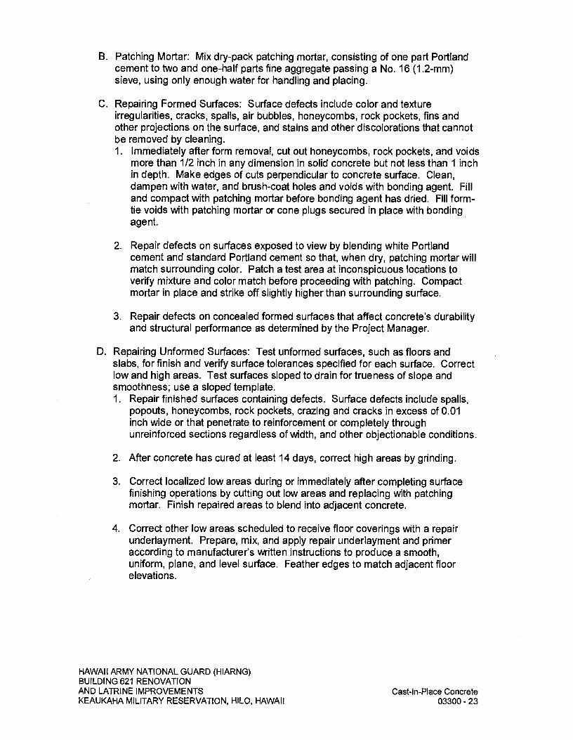
B. Patching Mortar: Mix dry-pack patching mortar, consisting of one part Portland cement to two and one-half parts fine aggregate passing a No. 16 (1.2-mm) sieve, using only enough water for handling and placing.
C. Repairing Formed Surfaces: Surface defects include color and texture irregularities, cracks, spalls, air bubbles, honeycombs, rock pockets, fins and other projections on the surface, and stains and other discolorations that cannot be removed by cleaning. 1. Immediately after form removal, cut out honeycombs, rock pockets, and voids
more than 1/2 inch in any dimension in solid concrete but not less than 1 inch in depth. Make edges of cuts perpendicular to concrete surface. Clean, dampen with water, and brush-coat holes and voids with bonding agent. Fill and compact with patching mortar before bonding agent has dried. Fill form-tie voids with patching mortar or cone plugs secured in place with bonding agent.
2. Repair defects on surfaces exposed to view by blending white Portland cement and standard Portland cement so that, when dry, patching mortar will match surrounding color. Patch a test area at inconspicuous locations to verify mixture and color match before proceeding with patching. Compact mortar in place and strike off slightly higher than surrounding surface.
3. Repair defects on concealed formed surfaces that affect concrete's durability and structural performance as determined by the Project Manager.
D. Repairing Unformed Surfaces: Test unformed surfaces, such as floors and slabs, for finish and verify surface tolerances specified for each surface. Correct low and high areas. Test surfaces sloped to drain for trueness of slope and smoothness; use a sloped template. 1. Repair finished surfaces containing defects. Surface defects include spalls,
popouts, honeycombs, rock pockets, crazing and cracks in excess of 0.01 inch wide or that penetrate to reinforcement or completely through unreinforced sections regardless of width, and other objectionable conditions.
2. After concrete has cured at least 14 days, correct high areas by grinding.
3. Correct localized low areas during or immediately after completing surface finishing operations by cutting out low areas and replacing with patching mortar. Finish repaired areas to blend into adjacent concrete.
4. Correct other low areas scheduled to receive floor coverings with a repair underlayment. Prepare, mix, and apply repair underlayment and primer according to manufacturer's written instructions to produce a smooth, uniform, plane, and level surface. Feather edges to match adjacent floor elevations.
HAWAII ARMY NATIONAL GUARD (HIARNG) BUILDING 621 RENOVATION AND LATRINE IMPROVEMENTS
Cast-in-Place Concrete
KEAUKAHA MILITARY RESERVATION, HILO, HAWAII
03300-23

5. Correct other low areas scheduled to remain exposed with a repair topping. Cut out low areas to ensure a minimum repair topping depth of 1/4-inch to match adjacent floor elevations. Prepare, mix, and apply repair topping and primer according to manufacturer's written instructions to produce a smooth, uniform, plane, and level surface.
6. Repair defective areas, except random cracks and single holes 1-inch or less in diameter, by cutting out and replacing with fresh concrete. Remove defective areas with clean, square cuts and expose steel reinforcement with at least 3/4-inch clearance all around. Dampen concrete surfaces in contact with patching concrete and apply bonding agent. Mix patching concrete of same materials and mix as original concrete except without coarse aggregate. Place, compact, and finish to blend with adjacent finished concrete. Cure in same manner as adjacent concrete.
7. Repair random cracks and single holes 1-inch or less in diameter with patching mortar. Groove top of cracks and cut out holes to sound concrete and clean off dust, dirt, and loose particles. Dampen cleaned concrete surfaces and apply bonding agent. Place patching mortar before bonding agent has dried. Compact patching mortar and finish to match adjacent concrete. Keep patched area continuously moist for at least 72 hours.
E. Perform structural repairs of concrete, subject to the Project Manager's approval, using epoxy adhesive and patching mortar.
F. Repair materials and installation not specified above may be used, subject to the Project Manager's approval.
3.17 FIELD QUALITY CONTROL A. Testing Agency: Engage a qualified independent testing and inspecting agency
to sample materials, perform tests, and submit test reports during concrete placement according to requirements specified in this Article.
B. Testing Services: Testing of composite samples of fresh concrete obtained according to ASTM C 172/C 172M shall be performed according to the following requirements: 1. Testing Frequency: Obtain one composite sample for each day's pour of
each concrete mix exceeding 5 cu. yd. (4 cu. m), but less than 25 cu. yd. (19 cu. m), plus one set for each additional 50 cu. yd. (38 cu. m) or fraction thereof.
2. Slump: ASTM C 143/C 143M; one test at point of placement for each composite sample, but not less than one test for each day's pour of each concrete mix. Perform additional tests when concrete consistency appears to change.
3. Air Content: ASTM C 231/C 231 M, pressure method, for normal-weight concrete; ASTM C 173/C 173M, volumetric method, for structural lightweight concrete; one test for each composite sample, but not less than one test for each day's pour of each concrete mix.
HAWAII ARMY NATIONAL GUARD (HIARNG) BUILDING 621 RENOVATION AND LATRINE IMPROVEMENTS
Cast-in-Place Concrete
KEAUKAHA MILITARY RESERVATION, HILO, HAWAII
03300-24

4. Concrete Temperature: ASTM C 1064/C 1064M; one test hourly when air temperature is 40 deg F (4.4 deg C) and below and when 80 deg F (27 deg C) and above, and one test for each composite sample.
5. Unit Weight: ASTM C 567/C 567M, fresh unit weight of structural lightweight concrete; one test for each composite sample, but not less than one test for each day's pour of each concrete mix.
6. Compression Test Specimens: ASTM C 31/C 31M; cast and laboratory cure one set of four standard cylinder specimens for each composite sample. a. Cast and field cure one set of four standard cylinder specimens for each
composite sample.
7. Compressive-Strength Tests: ASTM C 39/C 39M; test two laboratory-cured specimens at 7 days and two at 28 days. a. Test two field-cured specimens at 7 days and two at 28 days.
b. A compressive-strength test shall be the average compressive strength from two specimens obtained from same composite sample and tested at age indicated.
C. When strength of field-cured cylinders is less than 85 percent of companion laboratory-cured cylinders, Contractor shall evaluate operations and provide corrective procedures for protecting and curing in-place concrete.
D. Strength of each concrete mix will be satisfactory if every average of any three consecutive compressive-strength tests equals or exceeds specified compressive strength and no compressive-strength test value falls below specified compressive strength by more than 500 psi (3.4 MPa).
E. Test results shall be reported in writing to the Project Manager, concrete manufacturer, and Contractor within 48 hours of testing. Reports of compressive-strength tests shall contain Project identification name and number, date of concrete placement, name of concrete testing and inspecting agency, location of concrete batch in Work, design compressive strength at 28 days, concrete mix proportions and materials, compressive breaking strength, and type of break for both 7-and 28-day tests.
F. Nondestructive Testing: Impact hammer, sonoscope, or other nondestructive device may be permitted by the Project Manager but will not be used as sole basis for approval or rejection of concrete.
G. Moisture Vapor Emission Test: Standard test method meeting ASTM F 1869.
H. Alkalinity (pH Level) Testing: Standard test required for floor slabs and all wall and ceiling surfaces to receive painted finishes. Testing of concrete to receive paint finish may be conducted under SECTION 09900 - PAINTING.
HAWAII ARMY NATIONAL GUARD (HIARNG) BUILDING 621 RENOVATION AND LATRINE IMPROVEMENTS
Cast-in-Place Concrete
KEAUKAHA MILITARY RESERVATION, H1LO, HAWAII
03300-25
I. Additional Tests: Testing and inspecting agency shall make additional tests of concrete when test results indicate that slump, air entrainment, compressive strengths, or other requirements have not been met, as directed by the Project Manager. Testing and inspecting agency may conduct tests to determine adequacy of concrete by cored cylinders complying with ASTM C 42/C 42M or by other methods as directed by Project Manager.
END OF SECTION
HAWAII ARMY NATIONAL GUARD (HIARNG) BUILDING 621 RENOVATION AND LATRINE IMPROVEMENTS
Cast-in-Place Concrete
KEAUKAHA MILITARY RESERVATION, HILO, HAWAII
03300-26
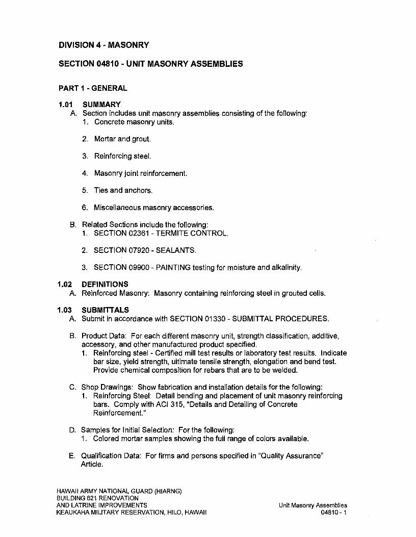
DIVISION 4- MASONRY
SECTION 04810 - UNIT MASONRY ASSEMBLIES
PART I - GENERAL
1.01 SUMMARY A. Section includes unit masonry assemblies consisting of the following:
I. Concrete masonry units.
2. Mortar and grout.
3. Reinforcing steel.
4. Masonry joint reinforcement.
5. Ties and anchors.
6. Miscellaneous masonry accessories.
B. Related Sections include the following: 1. SECTION 02361 - TERMITE CONTROL.
2.SECTION 07920 - SEALANTS.
3. SECTION 09900 - PAINTING testing for moisture and alkalinity.
1.02 DEFINITIONS A. Reinforced Masonry: Masonry containing reinforcing steel in grouted cells.
1.03 SUBMITTALS A. Submit in accordance with SECTION 01330 - SUBMITTAL PROCEDURES.
B. Product Data: For each different masonry unit, strength classification, additive, accessory, and other manufactured product specified. 1. Reinforcing steel - Certified mill test results or laboratory test results. Indicate
bar size, yield strength, ultimate tensile strength, elongation and bend test. Provide chemical composition for rebars that are to be welded.
C. Shop Drawings: Show fabrication and installation details for the following: 1. Reinforcing Steel: Detail bending and placement of unit masonry reinforcing
bars. Comply with ACI 315, "Details and Detailing of Concrete Reinforcement."
D. Samples for Initial Selection: For the following: 1. Colored mortar samples showing the full range of colors available.
E. Qualification Data: For firms and persons specified in "Quality Assurance" Article.
HAWAII ARMY NATIONAL GUARD (HIARNG) BUILDING 621 RENOVATION AND LATRINE IMPROVEMENTS
Unit Masonry Assemblies
KEAUKAHA MILITARY RESERVATION, HILO, HAWAII
04810-1

F. Material Certificates: Signed by manufacturers certifying that each of the following items complies with requirements: 1. Each cement product required for mortar and grout, including name of
manufacturer, brand, type, and weight slips at time of delivery.
2. Grout mixes. Include description of type and proportions of ingredients to assure compliance with ASTM C 476 or 2003 IBC Table 2103.10.
3. Each material and grade indicated for reinforcing bars.
4. Each type and size of joint reinforcement.
5. Each type and size of anchor, tie, and metal accessory.
G. Test Reports: Manufacturer's tests shall be in accordance with ASTM C 140 for conformance with the requirements of ASTM C 90.
H. Quality Control Inspection Documents: Provide one copy of the following industry documents for use by Project Manager. 1. NCMA TEK 8-2A (1998): Removal of Stains from Concrete Masonry Walls
1.04 QUALITY ASSURANCE A. Source Limitations for Masonry Units: Obtain exposed masonry units of a
uniform texture and color, or a uniform blend within the ranges accepted for these characteristics, through one source from a single manufacturer for each product required. 1. Block plant shall maintain a quality control program to monitor and control
block chloride ioncontent. Soluble chloride ion content should not exceed 0.30 per cent by volume of the cement material in the block, based on ACI 318-02 Table 4.4.1.
B. Source Limitations for Mortar Materials: Obtain mortar ingredients of a uniform quality, including color for exposed masonry, from one manufacturer for each cementitious component and from one source or producer for each aggregate.
1.05 DELIVERY, STORAGE, AND HANDLING A. Store masonry units on elevated platforms in a dry location. Carefully stack and
handle masonry units so as to prevent chipping, marring or cracking of corners, edges and faces.
B. Store cementitious materials on elevated platforms, under cover, and in a dry location. Do not use cementitious materials that have become damp.
C. Store aggregates where grading and other required characteristics can be maintained and contamination avoided.
D. Deliver preblended, dry mortar mix in moisture-resistant containers designed for lifting and emptying into dispensing silo. Store preblended, dry mortar mix in delivery containers on elevated platforms, under cover, and in a dry location or in a metal dispensing silo with weatherproof cover.
HAWAII ARMY NATIONAL GUARD (HIARNG) BUILDING 621 RENOVATION AND LATRINE IMPROVEMENTS
Unit Masonry Assemblies
KEAUKAHA MILITARY RESERVATION, HILO, HAWAII
04810-2

E. Store masonry accessories, including metal items, to prevent corrosion and accumulation of dirt and oil.
1.06 PROJECT CONDITIONS A. Protection of Masonry: In rainy locations and conditions, cover tops of walls,
projections and sills with waterproof sheeting to repel water.
B. Do not apply uniform floor or roof loads for at least 12 hours and concentrated loads for at least 3 days after building masonry walls or columns.
C. Stain Prevention: Protect to prevent stain damage to mar final finish or finishing techniques. Prevent grout, mortar, and soil from staining the face of masonry to be left exposed, stained or painted
D. Hot-Weather Requirements: Protect unit masonry work when temperature and humidity conditions produce excessive evaporation of water from mortar and grout. Provide artificial shade and wind breaks and use cooled materials as required. 1. When ambient temperature exceeds 90 deg F with a wind velocity greater
than 8 mph, do not spread mortar beds more than 48 inches ahead of masonry. Set masonry units within one minute of spreading mortar.
PART 2- PRODUCTS
2.01 CONCRETE MASONRY UNITS A. General: Provide shapes indicated and as follows:
1. Provide special shapes for lintels, corners, jambs, sash, headers, bonding, screen block, and other special conditions.
2. Provide square-edged units for outside corners, unless indicated as bulinose.
3. Provide "H" blocks for below grade foundation walls and scheduled to be fully grouted.
B. Concrete Masonry Units: ASTM C 90 and as follows: 1. Unit Compressive Strength: Provide load bearing units with minimum
average net-area compressive strength of 1900 psi.
2. Size (Width): Manufactured to the following dimensions within variations in dimensions only as permissible per ASTM C 90: a. 8-inch nominal width x 4-inch nominal height x 16-inch nominal length.
b. 12-inch nominal width x 4-inch nominal height x 16-inch nominal length.
c. 6-inch nominal width x 8-inch nominal height x 16-inch nominal length. Infill condition.
HAWAII ARMY NATIONAL GUARD (HIARNG) BUILDING 621 RENOVATION AND LATRINE IMPROVEMENTS
Unit Masonry Assemblies
KEAUKAHA MILITARY RESERVATION, HILO, HAWAII
04810-3

3. Texture: Match existing.
2.02 MORTAR AND GROUT MATERIALS A. Portland Cement: ASTM C 150/C 150M, Type II. Provide natural color or white
cement as required to produce mortar color indicated.
B. Mortar Cement: Shall comply with ASTM C 270, 2003 IBC Section 2103.7.
C. Masonry Cement: Shall comply with ASTM C 270, 2003 IBC Section 2103.7.
D. Aggregate for Mortar: ASTM C 144.
E. Aggregate for Grout: ASTM C 404.
F. Mortar Pigments: Natural and synthetic iron oxides and chromium oxides, compounded for use in mortar mixes. Use only pigments with a record of satisfactory performance in masonry mortar.
G. Water for use in mixing Mortar and Grout: Potable and complying with ASTM C 94/C 94M. Clean and free from injurious amounts of oils, acids alkalis, salts, organic materials or other substances that may be deleterious to both mortar and reinforcement.
2.03 REINFORCING STEEL A. Uncoated Steel Reinforcing Bars: ASTM A 615/A 615M; ASTM A 996/A 996M,
deformed, Grade 60 unless otherwise indicated on the drawings or specified herein.
2.04 MASONRY JOINT REINFORCEMENT A. General: Conform to ASTM A 951/A 951M and as follows:
1. Hot-dip galvanized, carbon-steel wire for both interior and exterior walls.
2. Wire Size for Side Rods: No. 9 (0.14-inch) diameter.
3. Wire Size for Cross Rods: No. 9 (0.14-inch) diameter.
4. Provide in lengths of not less than 10 feet. Provide prefabricated corner and tee units in lengths not less than two feet where indicated.
B. For single-wythe masonry, provide either ladder or truss type with single pair of side rods and cross rods spaced not more than 12 inches o.c.
2.05 TIES AND ANCHORS, GENERAL A. General: Provide ties and anchors, specified in subsequent articles, made from
materials that comply with this Article, unless otherwise indicated.
B. Hot-Dip Galvanized Carbon-Steel Wire: ASTM A 82/A 82M; with ASTM A 153/A 153M, Class B-2 coating.
HAWAII ARMY NATIONAL GUARD (HIARNG) BUILDING 621 RENOVATION AND LATRINE IMPROVEMENTS
Unit Masonry Assemblies
KEAUKAHA MILITARY RESERVATION, HILO, HAWAII
04810-4
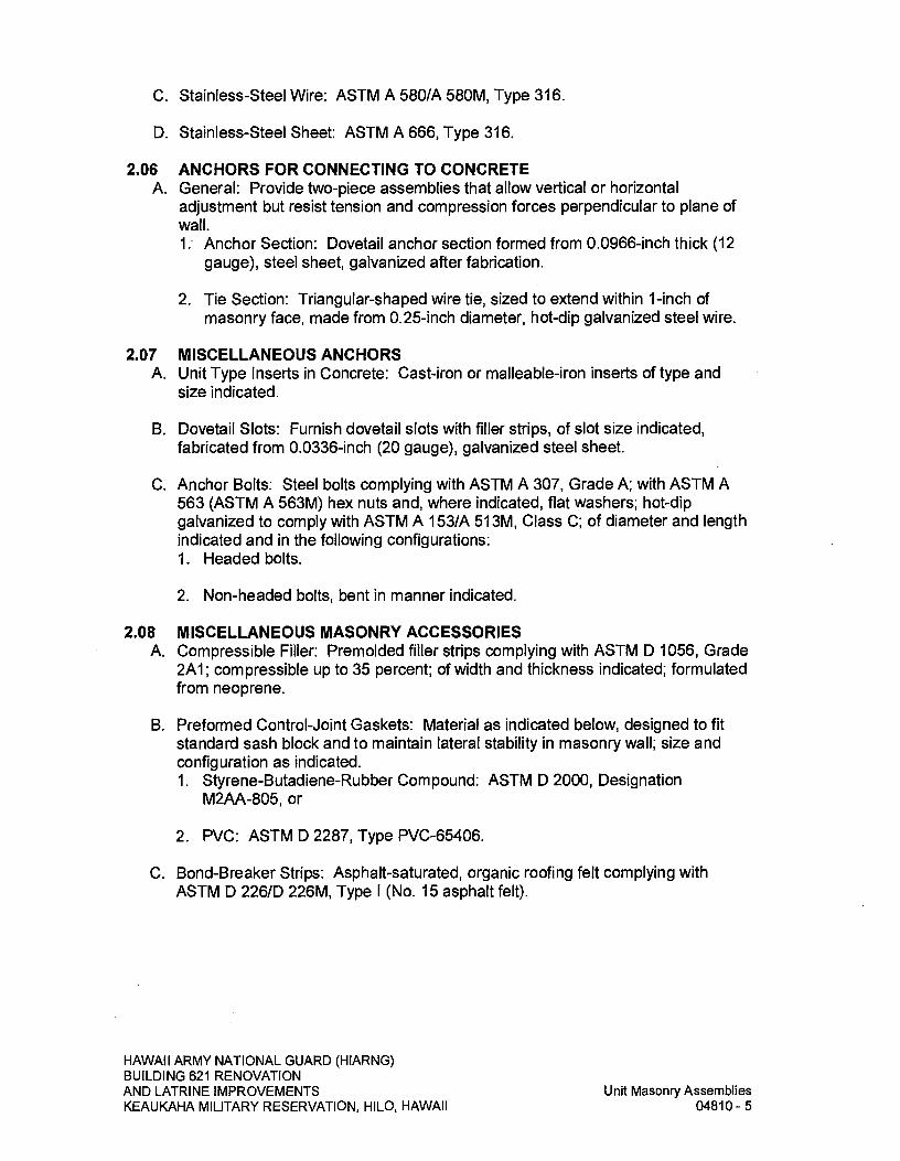
C. Stainless-Steel Wire: ASTM A 580/A 580M, Type 316.
D. Stainless-Steel Sheet: ASTM A 666, Type 316.
2.06 ANCHORS FOR CONNECTING TO CONCRETE A. General: Provide two-piece assemblies that allow vertical or horizontal
adjustment but resist tension and compression forces perpendicular to plane of wall. 1: Anchor Section: Dovetail anchor section formed from 0.0966-inch thick (12
gauge), steel sheet, galvanized after fabrication.
2. Tie Section: Triangular-shaped wire tie, sized to extend within 1-inch of masonry face, made from 0.25-inch diameter, hot-dip galvanized steel wire.
2.07 MISCELLANEOUS ANCHORS A. Unit Type Inserts in Concrete: Cast-iron or malleable-iron inserts of type and
size indicated.
B. Dovetail Slots: Furnish dovetail slots with filler strips, of slot size indicated, fabricated from 0.0336-inch (20 gauge), galvanized steel sheet.
C. Anchor Bolts: Steel bolts complying with ASTM A 307, Grade A; with ASTM A 563 (ASTM A 563M) hex nuts and, where indicated, flat washers; hot-dip galvanized to comply with ASTM A 153/A 513M, Class C; of diameter and length indicated and in the following configurations: 1. Headed bolts.
2. Non-headed bolts, bent in manner indicated.
2.08 MISCELLANEOUS MASONRY ACCESSORIES A. Compressible Filler: Premolded filler strips complying with ASTM D 1056, Grade
2A1; compressible up to 35 percent; of width and thickness indicated; formulated from neoprene.
B. Preformed Control-Joint Gaskets: Material as indicated below, designed to fit standard sash block and to maintain lateral stability in masonry wall; size and configuration as indicated. 1. Styrene-Butadiene-Rubber Compound: ASTM D 2000, Designation
M2AA-805, or
2. PVC: ASTM D 2287, Type PVC-65406.
C. Bond-Breaker Strips: Asphalt-saturated, organic roofing felt complying with ASTM D 226/D 226M, Type I (No. 15 asphalt felt).
HAWAII ARMY NATIONAL GUARD (HIARNG) BUILDING 621 RENOVATION AND LATRINE IMPROVEMENTS
Unit Masonry Assemblies
KEAUKAHA MILITARY RESERVATION, HILO, HAWAII
04810-5
D. Reinforcing Bar Positioners: Commercial plastic or wire units designed to fit into mortar bed joints spanning masonry unit cells with loops for holding reinforcing bars in center of cells. Units are formed from 0.187-inch steel wire, hot-dip galvanized after fabrication. Commercial plastic units are fabricated for the intended purpose. 1. Provide units with either two loops or four loops as needed for number of bars
indicated.
2. Other suitable devices: Other suitable devices may be used, upon proper submittal to and approval by Project Manager.
E. Adhesive: Type recommended by insulation board manufacturer for application indicated.
2.09 MASONRY CLEANERS A. Job-Mixed Detergent Solution: Solution of 1/2-cup dry measure tetrasodium
polyphosphate and 1/2-cup dry measure laundry detergent dissolved in 1-gallon of water.
B. Proprietary Acidic Cleaner: Manufacturer's standard-strength cleaner designed for removing mortar or grout stains, efflorescence, and other new construction stains from new masonry without discoloring or damaging masonry surfaces. Use product expressly approved for intended use by cleaner manufacturer and manufacturer of masonry units being cleaned.
2.10 MORTAR AND GROUT MIXES A. General: Do not use admixtures, including pigments, air-entraining agents,
accelerators, retarders, water-repellent agents, antifreeze compounds, or other admixtures, unless otherwise indicated. 1. Do not use calcium chloride in mortar or grout.
B. Pre-blended, Dry Mortar Mix: Furnish dry mortar ingredients in the form of a pre-blended mix. Measure quantities by weight to ensure accurate proportions, and thoroughly blend ingredients before delivering to the job site.
C. Mortar for Unit Masonry: 1. The proportioning of materials for mortar and grout shall be by volume and
done in such manner that the specified proportions can be controlled and accurately maintained. Measure fine aggregate in a damp loose condition. Mix materials in a mechanical batch mixer for at least 3 minutes for mortar and 5 minutes for grout, but do not mix more than 10 minutes. Hand mixing is permitted only for small batches of 3 cubic feet or. less.
2. Prepare Mortar Mix Design I with sufficient water to provide a workable consistency. Use and place mortar within 1-1/2 hours after mixing.
3. Prepare Mortar Mix Designs 2 through 5 strictly in accordance with the admixture manufacturer's instructions. Place mortar within 2-1/2 hours after mixing. No materials which start to set shall be retempered.
HAWAII ARMY NATIONAL GUARD (HIARNG) BUILDING 621 RENOVATION AND LATRINE IMPROVEMENTS
Unit Masonry Assemblies
KEAUKAHA MILITARY RESERVATION, HILO, HAWAII
04810-6

D. Mortar Mix Designs: Mortar shall be freshly prepared and uniformly mixed in one of the following proportions unless directed otherwise by manufacturer of plasticizer additive: 1. Mortar Mix i;
Type Mortar I part masonry cement 2-1/2 to 3 parts mortar aggregate
2. Mortar Mix 2; Type M Mortar 2 sacks 1/2 to I bag 6 cu. ft.
3. Mortar Mix 3; Type M Mortar: I sack 3 ounces 2-1/4 to 2-3/4 cu. ft.
Portland cement powdered plasticizer additive (7 pound bag) mortar aggregate
Portland cement liquid plasticizer additive mortar aggregate
E. Grout for Unit Masonry: Sufficient water shall be used to produce a consistency just fluid enough for pouring or pumping without segregation. Grout shall be used and placed in final position within 90 minutes after mixing, but shall in no case be used after initial set has occurred. This time limitation is permitted to be waived, if the grout is of such slump that it can be placed without addition of water. 1. Grout shall attain not less than 2,500 psi 28-day compressive strength per
ASTM C 1019 unless noted otherwise on drawings.
2. Use plasticizers additives for below grade foundation walls scheduled to be grouted to ensure full dispersal of mix.
F. Grout Mixes: conform to ASTM C 476 for grout mixed on-site. Prepare and uniformly mix grout in the following proportion: 1. Fine Grout
I part Portland cement Fine Aggregate: 2-1/4 to 5 times the sum of the volumes of the
cementitious materials
2. Ready-mix Grout: Conform to ASTM C 476 for grout designed by ready-mix suppliers.
PART 3- EXECUTION
3.01 EXAMINATION A. Examine conditions, with Installer present, for compliance with requirements for
installation tolerances and other conditions affecting performance. 1.
For the record, prepare written report, endorsed by Installer, listing conditions detrimental to performance.
HAWAII ARMY NATIONAL GUARD (H1ARNG) BUILDING 621 RENOVATION AND LATRINE IMPROVEMENTS
Unit Masonry Assemblies
KEAUKAHA MILITARY RESERVATION, HILO, HAWAII
04810-7

2. Verify that floor levels, footing levels or foundations are within tolerances specified.
3. Verify that reinforcing dowels are properly placed.
4. Proceed with installation only after unsatisfactory conditions have been corrected.
B. Before installation, examine rough-in and built-in construction to verify actual locations of piping connections.
3.02 INSTALLATION, GENERAL A. General: All masonry units shall be clean and handled to protect and minimize
chipping, spalling and cracking. All bed on which masonry is to be laid shall be clean.
B. Masonry units shall not be wetted prior to use. Units which have become wet shall be allowed to dry thoroughly before laying. If water is splashed on the block and a color difference does not occur (from the water) then the block units are too wet to be laid. (Source: Reinforced Concrete Masonry Construction Inspector's Handbook, Fourth Edition, paragraph 12.3.4)
C. Build chases and recesses to accommodate items specified in this Section and in other Sections of the Specifications.
D. Leave openings for equipment to be installed before completing masonry. After installing equipment, complete masonry to match the construction immediately adjacent to the opening.
E. Cut masonry units with motor-driven saws to provide clean, sharp, unchipped edges. Cut units as required to provide a continuous pattern and to fit adjoining construction. Where possible, use full-size units without cutting. Allow units cut with water-cooled saws to dry before placing, unless wetting of units is specified. Install cut units with cut surfaces and, where possible, cut edges concealed.
F. Select and arrange units for exposed unit masonry to produce a uniform blend of colors and textures.
3.03 CONSTRUCTION TOLERANCES A. Comply with the tolerances in the national concrete masonry association
Specification for Structures ACI 530-02/ASCE 6/TMS 602 as applicable to climate indigenous to Hawaii and as noted.
B. For conspicuous vertical lines, such as external corners, door jambs, reveals, and expansion and control joints, do not vary from plumb by more than 1/4-inch in 20 feet, nor 1/2-inch maximum.
C. For vertical alignment of exposed head joints, do not vary from plumb by more than 1/4-inch in 10 feet, nor 1/2-inch maximum.
HAWAII ARMY NATIONAL GUARD (HIARNG) BUILDING 621 RENOVATION AND LATRINE IMPROVEMENTS
Unit Masonry Assemblies
KEAUKAHA MILITARY RESERVATION, HILO, HAWAII
04810-8

D. For conspicuous horizontal lines, such as exposed lintels, sills, parapets, and reveals, do not vary from level by more than 1/4-inch in 20 feet, nor 1/2-inch maximum.
E. For exposed bed joints, do not vary from thickness indicated by more than plus or minus 1/8-inch, with a maximum thickness limited to 1/2-inch. Do not vary from bed-joint thickness of adjacent courses by more than 1/8-inch.
F. For exposed head joints, do not vary from thickness indicated by more than plus or minus 1/8-inch. Do not vary from adjacent bed-joint and head-joint thicknesses by more than 1/8-inch.
3.04 LAYING MASONRY WALLS A. Lay out walls in advance for accurate spacing of surface bond patterns with
uniform joint thicknesses and for accurate location of openings, movement-type joints, returns, and offsets. Avoid using less-than-half-size units, particularly at corners, jambs, and, where possible, at other locations.
B. When foundation is at specified levels, lay first course masonry units in a mortar bed not exceeding 3/4-inch thick. Bed webs of adjoining cells that contain reinforcement in mortar-to prevent escape of grout.
C. Bond Pattern for Exposed Masonry: Lay exposed masonry in the following bond pattern; do not use units with less than nominal 4-inches horizontal face dimensions at corners or jambs. 1. One-half running bond with vertical joint in each course centered on units in
courses above and below unless otherwise indicated on Drawings.
2. Stack bond for screen block.
3. As indicated on Drawings.
D. Lay concealed masonry with all units in a wythe in running bond or bonded by lapping not less than 2 inches. Bond and interlock each course of each wythe at corners. Do not use units with less than nominal 4-inches horizontal face dimensions at corners or jambs.
E. Stopping and Resuming Work: In each course, rack back one-half-unit length for one-half running bond; do not tooth. Clean exposed surfaces of set masonry and remove loose masonry units and mortar before laying fresh masonry.
F. Built-in Work: As construction progresses, build in items specified under this and other Sections of the Specifications. Fill in solidly with masonry around built-in items.
G. Grout space between hollow-metal frames and masonry solidly with mortar, unless otherwise indicated. 1. Grout mix: Use one of the following.
a. One of the mortars mixed specified in Part 2 above.
b. One of the grout mixes specified in Part 2 above.
HAWAII ARMY NATIONAL GUARD (HIARNG) BUILDING 621 RENOVATION AND LATRINE IMPROVEMENTS
Unit Masonry Assemblies
KEAUKAHA MILITARY RESERVATION, HILO, HAWAII
04810-9
2. Gypsum board joint compound or other gypsum containing compounds are not permitted.
H. Where built-in items are to be embedded in cores of hollow masonry units, place a layer of metal lath in the joint below and rod mortar or grout into core.
I. Cores in hollow concrete masonry units shall be fully grouted solid.
J. Fill cores in hollow concrete masonry units with grout for foundation walls and below grade walls up to underside of floor slab unless otherwise indicated.
K. Build non-load-bearing interior partitions full height of story to underside of solid floor or roof structure above, unless otherwise indicated. 1. Install compressible filler in joint between top of partition and underside of
structure above.
3.05 MORTAR BEDDING AND JOINTING A. Lay hollow masonry units as follows:
1. With full mortar coverage on horizontal and vertical face shells.
2. Bed webs in mortar in starting course on footings and in all courses of piers, columns, and pilasters, and where adjacent to cells or cavities to be filled with grout.
3. For starting course on footings where cells are not grouted, spread out full mortar bed, including areas under cells.
4. Bed cross webs.
B. Lay solid brick-size masonry units with completely filled bed and head joints; butter ends with sufficient mortar to fill head joints and shove into place. Do not deeply furrow bed joints or slush head joints.
C. Lay horizontal-cell units with full bed joints, unless otherwise indicated. Keep drainage channels, if any, free of mortar. Form head joints with sufficient mortar so excess will be squeezed out as units are placed in position. Butter both sides of units to be placed, or butter one side of unit already in place and one side of unit to be placed.
D. Maintain joint thicknesses indicated, except for minor variations required to maintain bond alignment. If not indicated, lay walls with 1/4- to 3/8-inch thick joints.
E. Mortar joint tooling shall match existing.
F. Cut joints flush for masonry walls to receive plaster or other direct-applied finishes (other than paint), unless otherwise indicated.
HAWAII ARMY NATIONAL GUARD (HIARNG) BUILDING 621 RENOVATION AND LATRINE IMPROVEMENTS
Unit Masonry Assemblies
KEAUKAHA MILITARY RESERVATION, H1LO, HAWAII
04810-10

3.06 BONDING OF MASONRY A. Intersecting and Abutting Walls: Unless vertical expansion or control joints are
shown at juncture, bond walls together as follows: 1.
Provide continuity with masonry joint reinforcement by using prefabricated "T" units and lap masonry horizontal reinforcing bars as indicated in the drawings.
3.07 MASONRY JOINT REINFORCEMENT A. General: Provide continuous masonry joint reinforcement as indicated. Install
entire length of longitudinal side rods in mortar with a minimum cover of 5/8-inch on exterior side of walls, 1/2-inch elsewhere. Lap reinforcement a minimum of six (6) inches. 1. Space reinforcement not more than 12 inches o.c.
2. Space reinforcement not more than 8 inches o.c. in foundation walls and parapet walls.
3. Provide reinforcement not more than 8 inches above and below wall openings and extending 12 inches beyond openings. a. Reinforcement above is in addition to continuous reinforcement.
B. Cut or interrupt joint reinforcement at control and expansion joints, unless otherwise indicated.
C. Provide continuity at corners and wall intersections by using prefabricated "L" and "T" sections. Cut and bend reinforcing units as directed by manufacturer for continuity at returns, offsets, column fireproofing, pipe enclosures, and other special conditions.
3.08 ANCHORING MASONRY TO STRUCTURAL MEMBERS A. Anchor masonry to structural members where masonry abuts or faces structural
members to comply with the following: 1. Anchor masonry to structural members with flexible anchors embedded in
masonry joints and attached to structure.
2. Space anchors as indicated, but not more than 24 inches o.c. vertically and 36 inches o.c. horizontally.
3.09 CONTROL AND EXPANSION JOINTS A. General: Install control and expansion joints in unit masonry where indicated.
Build-in related items as masonry progresses. Do not form a continuous span through movement joints unless provisions are made to prevent in-plane restraint of wall or partition movement.
B. Form control joints in concrete masonry as follows: 1. Fit bond-breaker strips into hollow contour in ends of concrete masonry units
on one side of control joint. Fill resultant core with grout and rake joints in exposed faces.
2. Install preformed control-joint gaskets designed to fit standard sash block.
HAWAII ARMY NATIONAL GUARD (HIARNG) BUILDING 621 RENOVATION AND LATRINE IMPROVEMENTS
Unit Masonry Assemblies
KEAUKAHA MILITARY RESERVATION, HILO, HAWAII
04810-11
3. Install interlocking units designed for control joints. Install bond-breaker strips at joint. Keep head joints free and clear of mortar or rake joint.
4. Install temporary foam-plastic filler in head joints and remove excess filler and seal joint when unit masonry is complete.
C. Build in horizontal, pressure-relieving joints where indicated; construct joints by either leaving an air space or inserting a compressible filler of width required for installing sealant and backer rod specified in SECTION 07920 - SEALANTS. 1. Locate horizontal, pressure-relieving joints beneath shelf angles supporting
masonry veneer and attached to structure behind masonry veneer.
3.10 LINTELS A. Install steel lintels where indicated.
B. Provide masonry lintels where shown without structural steel or other supporting lintels. 1. Provide prefabricated or built-in-place masonry lintels. Use specially formed
bond beam units with reinforcing bars placed as indicated and filled with grout. Cure precast lintels before handling and installing. Temporarily support built-in-place lintels until cured.
C. Provide minimum bearing of 8 inches at each jamb, unless otherwise indicated.
3.11 REINFORCED UNIT MASONRY INSTALLATION A. Temporary Formwork and Shores: Construct formwork and shores to support
reinforced masonry elements during construction. 1. Construct formwork to conform to shape, line, and dimensions shown. Make
it tight to prevent leakage of mortar and grout. Brace, tie, and support forms to maintain position and shape during construction and curing of reinforced masonry.
2. Do not remove forms and shores until reinforced masonry members have hardened sufficiently to carry their own weight and other temporary loads that may be placed on them during construction.
B. Placing Reinforcement: Comply with requirements ACI 530 Sec 3.4/ASCE 6/TMS 602. Rebars shall be secured within cell by rebar positioners prior to grouting.
C. Grouting: Do not place grout until entire height of masonry to be grouted has attained sufficient strength to resist grout pressure. 1. Comply with requirements of ACI 530 Sec. 3.5/ASCE 6/TMS 602 for
cleanouts and for grout placement, including minimum grout space and maximum pour height.
3.12 REPAIRING, POINTING, AND CLEANING A. Remove and replace masonry units that are loose, chipped, broken, stained, or
otherwise damaged or that do not match adjoining units. Install new units to match adjoining units; install in fresh mortar, pointed to eliminate evidence of replacement.
HAWAII ARMY NATIONAL GUARD (HIARNG) BUILDING 621 RENOVATION AND LATRINE IMPROVEMENTS
Unit Masonry Assemblies
KEAUKAHA MILITARY RESERVATION, HILO, HAWAII
04810-12

B. Pointing: During the tooling of joints, enlarge voids and holes, except weep holes, and completely fill with mortar. Point up joints, including corners, openings, and adjacent construction, to provide a neat, uniform appearance. Prepare joints for sealant application.
C. In-Progress Cleaning: Clean unit masonry as work progresses by dry brushing to remove mortar fins and smears before tooling joints.
D. Final Cleaning: After mortar is thoroughly set and cured, clean exposed masonry as follows: 1. Remove large mortar particles by hand with wooden paddles and nonmetallic
scrape hoes or chisels.
2. Protect adjacent stone and non-masonry surfaces from contact with cleaner by covering them with liquid strippable masking agent, polyethylene film, or waterproof masking tape.
3. Wet wall surfaces with water before applying cleaners; remove cleaners promptly by rinsing the surfaces thoroughly with clear water.
4. Clean concrete masonry by cleaning method indicated in NCMA TEK 8-2 applicable to type of stain on exposed surfaces.
END OF SECTION
HAWAII ARMY NATIONAL GUARD (HIARNG) BUILDING 621 RENOVATION AND LATRINE IMPROVEMENTS
Unit Masonry Assemblies
KEAUKAHA MILITARY RESERVATION, HILO, HAWAII
04810-13

DIVISION 5- METALS
SECTION 05500 - METAL FABRICATIONS
PART I - GENERAL
1.01 SUMMARY A. Provide all miscellaneous metal fabrication work, including, but not limited to, the
following: 1. Metal railings and guardrails.
2. Expanded metal transom panel.
3. Ceiling supported toilet partitions.
4. Miscellaneous fabrications.
5. Furnish miscellaneous steel attachments, anchors, plates, angles, etc., to be set in concrete.
6. Include all anchors, angles, bolts, expansion shields for items in this section only, and other accessories shown in details and/or required for the complete installation of all work.
1.02 SUBMITTALS A. Submit in accordance with SECTION 01330 - SUBMITTAL PROCEDURES.
B. Manufacturer's Data: Submit manufacturers product data for all manufactured products. Include color charts for all materials exposed and requiring selection of finish color.
C. Shop Drawings: Submit shop drawings for fabrication and erection of miscellaneous metal fabrications. Include plans, elevations, and details of sections and connections. Show anchorage and accessory items. Provide templates for anchor and bolt installation by others under this project. Where materials or fabrications are indicated to comply with certain requirements for design loadings include structural computations, material properties, and other information needed for structural analysis. Indicate weld connections using standard AWS welding symbols.
1.03 QUALITY ASSURANCE A. Field Measurements: Take field measurements prior to preparation of shop
drawings and fabrication, where possible. Do not delay job progress; allow for trimming and fitting where taking field measurements before fabrication might delay work.
HAWAII ARMY NATIONAL GUARD (HIARNG) BUILDING 621 RENOVATION AND LATRINE IMPROVEMENTS
MetI Fabrications
KEAUKAHA MILITARY RESERVATION, HILO, HAWAII
05500-1
B. Shop Assembly: Preassemble items in shop to greatest extent possible to minimize field splicing and assembly. Disassemble units only as necessary for shipping and handling limitations. Clearly mark units for reassembly and coordinated installation.
C. Qualifications of Welders: Only welders certified in the arc welding process shall perform work in connection with the work in this section. Comply with AWS D1. 1 /D1.1 M for welding procedure and performance qualification.
1.04 SYSTEM PERFORMANCE REQUIREMENTS A. General: Engineer systems to withstand structural loads indicated, determine
allowable design working stresses of materials based on the following: 1. Cold-Formed Structural Steel: AISI "Specification for Design of Cold-Formed
Steel Structural Members".
B. Structural Performance of Handrails and Railings: Provide handrails and railings capable of withstanding structural loads required by the current ICC IBC Section 1607.7.1 Handrails and Guards as amended and ASTM E 985 but not less than the following structural loads without exceeding allowable design working stress of materials for handrails, railings, anchors, and connections based on testing performed in accordance with ASTM E 894 and ASTM E 935: 1. Top Rail of Guards: Capable of withstanding the following loads applied as
indicated: a. Concentrated load of 200 pounds applied at any point and in any
direction.
b. Uniform load of 50 pounds per linear foot applied horizontally and concurrently with uniform load of 100 pounds per linear foot applied vertically downward.
c. Concentrated and uniform loads above need not be assumed to act concurrently.
2. Handrails Not Serving As Top Rails: Capable of withstanding the following loads applied as indicated: a. Concentrated load of 200 pounds applied at any point and in any
direction.
b. Uniform load of 50 pounds per linear foot applied in any direction.
c. Concentrated and uniform loads above need not be assumed to act concurrently.
3. Infill Area of Guards: Capable of withstanding a horizontal concentrated load of 200 pounds applied to I square foot at any point in system, including panels, intermediate rails, balusters, or other elements composing infill area. Load above need not be assumed to act concurrently with loads on top rails in determining stress on guard.
HAWAII ARMY NATIONAL GUARD (F-IIARNG) BUILDING 621 RENOVATION AND LATRINE IMPROVEMENTS
Metal Fabrications
KEAUKAHA MILITARY RESERVATION, HILO, HAWAII
05500-2

4. The structural strength of all metal railings and guardrails and all fasteners and mounting devices shall meet or exceed the accessibility requirements (250 lbf) of ADAAG Section 609.8.
C. Thermal Movements: Provide handrails and railings that allow for thermal movements resulting from the following maximum change (range) in ambient and surface temperatures by preventing buckling, opening of joints, overstressing of components, failure of connections, and other detrimental effects. Base engineering calculation on surface temperatures of materials due to both solar heat gain and nighttime-sky heat loss. 1. Temperature Change (Range): 40 degrees F, ambient; 120 degrees F,
material surfaces.
1.05 DELIVERY, STORAGE, AND HANDLING A. General: Deliver, store, and handle materials in strict conformance of the
manufacturer's instructions and recommendations.
B. Protection: The Contractor shall use all means necessary to protect all materials before, during, and after installation and to protect the installed work and materials of all other trades.
C. Replacement: In the event of damage, the Contractor shall immediately make all repairs and replacements necessary to the satisfaction of the Project Manager and at no additional cost to the State.
PART 2- PRODUCTS
2.01 MATERIALS A. Structural Steel Shapes, Plates, and Bars: ASTM A 36/A 36M.
B. Steel Pipe: ASTM A 53/A 53M; Type and grade (if applicable) as selected by fabricator and as required for design loading; hot-dipped galvanized, G90; standard weight (schedule 40), unless otherwise indicated.
C. Steel Tube: ASTM A 500/A 500M Grade B or ASTM A 501.
D. Electrodes for Welding: Comply with AWS Code. Use E70)(X electrodes unless recommended otherwise for the specified metal.
E. Anchors and Fasteners: Where exposed, shall be of the same material, color, and finish as the metal to which applied. 1. Expansion Shields: Expansion anchors shall be carbon steel threaded studs
with integral tapered cone expanders and segmented expansion collars. Provide anchors with electroplated zinc coating, length identification markings, and required nuts and washers. Expansion anchors shall be evaluated in accordance with ACI 355.2/355.2R, Category I or 2 and shall be tested in accordance with ICC ES AC 193 for all mandatory and optional tests. Provide shields recessed not less than 2-1/2 inches into concrete or masonry, unless as directed by the manufacturer.
HAWAII ARMY NATIONAL GUARD (HIARNG) BUILDING 621 RENOVATION AND LATRINE IMPROVEMENTS
Metal Fabrications
KEAUKAHA MILITARY RESERVATION, HILO, HAWAII
05500-3
2. Lag Screws and Bolts: ANSI/ASME B18.2.1, type and grade best suited for the purpose.
3. Toggle Bolts: ANSI/ASME B18.2.1.
4. Bolts, Nuts, Studs, and Rivets: ANSI/ASME B18.2.2 and ASTM A 307.
5. Powder Driven Fasteners: Follow safety provisions of ASSE/SAFE Al 0.3.
6. Screws: ANSI/ASME B18.2.1, ANSI/ASME B18.6.2, and ANSI/ASME BI 8.6.3.
7. Washers: Provide plain washers to conform to ANSI/ASME B18.22.1. Provide beveled washers for American Standard beams and channels, square or rectangular, tapered in thickness, and smooth. Provide lock washers to conform to ANSI/ASME BI 8.21.1.
8. Metal Anchor Bolts, Straps, Hangers, Brackets, and Other Inserts: Furnish to other trades the anchor bolts, straps, hangers, brackets, and other inserts which are necessary for the final installation of work under this and other trades, where not specified to be furnished under the other sections of the specifications. This trade shall also furnish templates if required by others and shall check the installation of all bolts and inserts for accuracy. Anchor bolts and washers of same quality as bolt.
9. Finish: All fasteners shall be hot dip galvanized except as indicated or specified otherwise. Exterior fasteners shall be stainless steel.
F. Shop Paint: I. Metal Primer Paint: Fabricator's standard fast-curing, "universal" primer free
from asbestos, lead, mercury, chromate, and cadmium, and compatible with finish paint systems.
2. Coordinate selection of metal primer with finish paint requirements specified in SECTION 09900 - PAINTING.
G. Galvanizing Repair Paint: SSPC - Paint 20.
H. Nonshrink Nonferrous Cementitious Grout: ASTM C 1107/C 1107M, BASF "MasterFiow II OAN", Anti-Hydro Co. "Axpanacrete", Thoro System Products "Thorogrip", or accepted equivalent non-metallic grout, premixed, specially manufactured for this purpose, with mix and setting characteristics as recommended by the manufacturer for the purpose intended. Use as fill for embedment of railing posts in floor sockets and for similar uses. Mix and place in strict accordance with manufacturer's instructions.
HAWAII ARMY NATIONAL GUARD (HIARNG) BUILDING 621 RENOVATION AND LATRINE IMPROVEMENTS
Metal Fabrications
KEAUKAHA MILITARY RESERVATION, HILO, HAWAII
05500-4

I. Insect Screen: Insect screens shall be provided for open transom units unless noted otherwise. Screens shall conform to ANSI/AAMA 101. Screen fabric shall be 14 x 18 or 16 x 18 mesh fiberglass, stationary, unless indicated or accepted otherwise, as selected by the Project Manager. Screen fabric color shall be charcoal gray.
J. Transom Panel: McNichols Quality Expanded Metal, 3/4 #9 standard, galvanized after expanded or accepted equivalent.
K. Bituminous Paint: Cold-applied asphalt mastic complying with SSPC-Paint 12 but containing no asbestos fibers, or cold-applied asphalt emulsion complying with ASTM D 1187.
2.02 FABRICATION A. Workmanship:
1. Use materials of size and thickness shown or, if not shown, of required size and thickness to produce strength and durability in finished product. Work to dimensions shown or accepted on shop drawings, using proven details of fabrication and support. Use type of materials shown or specified for various components of work.
2. Form exposed work true to line and level with accurate angles and surfaces and straight sharp edges. Ease exposed edges to a radius of approximately 1/32-inch unless otherwise shown. Form bent-metal corners to smallest radius possible without causing grain separation or otherwise impairing work.
3. Provide for anchorage of type shown, coordinated with supporting structure. Fabricate and space anchoring devices to provide adequate support for intended use.
4. Cut, reinforce, drill, and tap miscellaneous metal work as indicated to receive finish hardware and similar items.
5. Provide weep holes or another means to drain entrapped water in hollow sections of members that are exposed to exterior or to moisture from condensation or other sources. Fill voids below weep level to assure utility of weep holes.
B. Welding shall be done by approved certified welders who have been previously qualified by tests. Welding shall be in accordance with AWS D1.1/D1.IM for steel. Any welds which are found to be defective must be cut out and replaced. "Code for Arc and Gas Welding in Building Construction", latest edition, Sections II, III, and IV formulated by American Welding Society, shall be followed in design and execution of structural welding. 1. All welding of steel shall be done by electric-arc process with coated rods,
not fluxed, so as to produce shielded arc, and shall comply with the requirements of above specified manual.
2. Surfaces, seams, or joints to be welded shall be free from rust, scale, grease, and other foreign material.
HAWAII ARMY NATIONAL GUARD (HIARNG) BUILDING 621 RENOVATION AND LATRINE IMPROVEMENTS
Metal Fabrications
KEAUKAHA MILITARY RESERVATION, H1LO, HAWAII
05500-5

3. All welds shall be ground and pressed smooth and all weld flux, slag, and spatter shall be completely removed.
4. Connections not indicated shall be designed and provided by the Contractor and shall be made to conform with A1SC ASD Manual of Steel Construction, Vol Il: Connections. Develop full strength of members in all connections. One side connections will not be permitted.
5. Do not tack weld exposed connections.
6. Grind smooth visible welds in finished installation and clean welds immediately by chipping or wire brushing.
C. Galvanizing: Provide a zinc coating for those items shown or specified to be galvanized, as follows: 1. ASTM A 153/A 153M for galvanizing iron and steel hardware.
2. ASTM A 123/A 123M for galvanizing rolled, pressed and forged steel shapes, plates, bars and strip 1/8-inch thick and heavier; and for assembled steel products.
3. Provide minimum G90 coating designation.
D. Surface Preparation: Prepare ferrous metal surfaces to comply with minimum requirements indicated below for SSPC surface preparation specifications and environmental exposure conditions of installed metal fabrications: 1. Exteriors (SSPC Zone 113): SSPC-SP6 "Commercial Blast Cleaning".
2. Interior (SSPC Zone IA): SSPC-SP3 "Power Tool Cleaning".
E. Shop Painting: 1. Shop paint miscellaneous steel metal work, except galvanized surfaces and
surfaces to be embedded into concrete, unless otherwise specified.
2. immediately after surface preparation, brush or spray on primer in accordance with manufacturer's instructions, and at a rate to provide uniform dry film thickness of 2.0 mils for each coat. Use painting methods which will result in full coverage of joints, corners, edges, and exposed surfaces.
F. Repair of Damaged Zinc-Coated Surfaces: ASTM A 780/A 780M, Annexes Al, "Repair Using Zinc-Based Alloys", A2, "Repair Using Zinc-Rich Paints", or A3, "Repair Using Sprayed Zinc (Metallizing)".
G. Miscellaneous Framing and Supports: 1. Provide miscellaneous steel framing and supports as required to complete
work.
HAWAII ARMY NATIONAL GUARD (HIARNG) BUILDING 621 RENOVATION AND LATRINE IMPROVEMENTS
Metal Fabrications
KEAUKAHA MILITARY RESERVATION, HILO, HAWAII
05500-6

2. Fabricate miscellaneous units to sizes, shapes, and profiles shown or, if not shown, of required dimensions to receive adjacent other work to be retained by framing. Except as otherwise shown, fabricate from structural steel shapes and plates and steel bars. Cut, drill, and tap units to receive hardware and similar items.
2.03 METAL FINISHES A. Steel: Galvanized and treated for painting under SECTION 09900 - PAINTING
unless indicated or specified otherwise.
2.04 ANCHORAGE, FASTENINGS, AND CONNECTIONS A. Anchorage: Provide anchorage for fastening work securely in place. Set
anchors in concrete as work progresses and space maximum 2-feet on centers, unless indicated otherwise. Sizes, kinds, and spacings of anchors not indicated or specified shall be as necessary for the purpose, as accepted. Anchorage not otherwise specified or indicated includes slotted inserts, expansion shields, and powder-driven fasteners, when accepted for concrete; toggle bolts and through bolts for masonry; machine and carriage bolts for steel; through bolts, lag bolts, and screws for wood. Provide inserts of suitable and accepted types where required for support or anchorage of equipment and finish construction. Inserts shall be gray or malleable iron castings or galvanized steel unless indicated or specified otherwise. Slotted inserts shall be of types required to engage with anchors, except where specified otherwise.
B. Fastenings: Do not use wood plugs in any material. Use non-ferrous attachments for non-ferrous metal. Make exposed fastenings of compatible materials, generally matching in color and finish, and harmonizing with the material to which fastenings are applied. Conceal fastenings where practicable. Drill and punch to produce clean true lines and surfaces. Countersink metal work to receive hardware.
C. Threaded Connections: Make threaded connections up tight so that threads are entirely concealed. Make bolted work up tight and nick the threads or bush the stem to prevent loosening. Abutting bars shall be shouldered and headed, dowelled and pinned. Pass small bars through larger bars and pin. Rivet, bolt, and screw heads shall be flat and countersunk in exposed work and elsewhere as required. Machine removable members and fit and secure by means of screws or bolts of proper size and accepted spacing.
D. Anchors and Connecting Members: Provide in concrete or masonry as the work progresses, to avoid unnecessary cutting and drilling. Cut, fit, and drill as necessary so materials are properly set in place and to permit engaging work to be properly installed.
E. Design Connections: AISC "Detailing for Steel Construction"; where not shown or indicated otherwise, provide connections using common steel bolts. Provide necessary holes for securing work to building. Use lock washers under nuts.
HAWAII ARMY NATIONAL GUARD (HIARNG) BUILDING 621 RENOVATION AND LATRINE IMPROVEMENTS
Metal Fabrications
KEAUKAHA MILITARY RESERVATION, HILO, HAWAII
05500-7

F. Built-In Work: Form metal work built-in with concrete or masonry for anchorage, or provided with suitable anchoring devices as shown or as required. Furnish metal work in ample time for securing in place as work progresses.
G. Grouting: Grout metal fabrications and anchors in a manner that will assure filling of spaces and intimate contact of grouting materials with surface to be grouted. Place grout rapidly and continuously so to avoid cold joints and voids.
PART 3- EXECUTION
3.01 PREPARATION A. Field Measurements: Take field measurements prior to preparation of shop
drawings and fabrication, where possible, do not delay job progress; allow for trimming and fitting where taking field measurements before fabrication might delay work.
B. Coordinate and furnish anchorages, setting drawings, diagrams, templates, instructions, and directions for installation of anchorages, such as concrete inserts, sleeves, anchor bolts and miscellaneous items having integral anchors, which are to be embedded in concrete or masonry construction. Coordinate delivery of such items to project site.
C. Protection from Contact of Dissimilar Materials: Surfaces in contact with dissimilar metal shall be painted with heavy-bodied bituminous paint of shall be separated by means of moisture-proof building felts.
3.02 INSTALLATION A. Fastening to In-Place Construction: Provide anchorage devices and fasteners
where necessary for securing miscellaneous metal fabrications to in-place construction; including, toggle bolts, throughbolts, lag bolts, wood screws, and other connectors as required.
B. Cutting, Fitting, and Placement: Perform cutting, drilling, and fitting required for installation of miscellaneous metal fabrications. Set work accurately in location, alignment and elevation, plumb, level, true and free of rack, measured from established lines and levels.
C. Fit exposed connections accurately together to form tight hairline joints. Weld connections which are not to be left as exposed joints, but cannot be shop welded because of shipping size limitations. Grind exposed joints smooth, and touch-up shop paint coat. Do not weld, cut, or abrade the surfaces of exterior units which have been hot-dip galvanized after fabrication and are intended for bolted or screwed field connections.
D. Field Welding: Comply with AWS Code for procedures of manual shielded metal-arc welding, appearance and quality of weld made, and methods in correcting welding work.
HAWAII ARMY NATIONAL GUARD (HIARNG) BUILDING 621 RENOVATION AND LATRINE IMPROVEMENTS
Metal Fabrications
KEAUKAHA MILITARY RESERVATION, HILO, HAWAII
05500-8
E. Align rails so that variations from level for horizontal members, parallel for aligned members, and rake for steps, ramps, and sloped members shall not exceed 1/4-inch in 12-feet.
F. Transom Screens: Fabricate combination expanded metal and fiberglass insect screen combination to be fixed in hollow metal transom frames as provided under SECTION 08110- STEEL DOORS AND FRAMES as indicated. Expanded metal shall not be removable from exterior.
G. False Work: Provide guys, braces, and false work for temporary support of parts of the work and remove when work is self-supporting.
303 MISCELLANEOUS METAL FABRICATIONS A. The following fabricated assemblies are described in brief outline to indicate, in
addition to the drawings, the general design and details desired. Standard products of manufacturers specializing in similar work will be considered insofar as they fulfill the requirements and do not violate governing codes for building and standards of good construction work. Hot dip galvanize steel components after fabrication in as large components as possible. 1. Handrail General: To maximum extent practicable, railing shall be shop
fabricated. Rigid joints shall be flush-finished welded assembly. Joints shall be reinforced with tight fitting interior sleeves and shall be assembled by welding rails and posts to flush-type fittings, or by mitering and welding joining rails to posts. Expansion joints shall be located at lengths of rails as recommended by the manufacturer. Expansion joints shall be the inner-sleeved slip joint type with one end of the sleeve secured to the railing. Expansion joints and splices shall be located near the intersection of rails and posts. Bends in railing shall be smooth and made in a manner that will not crush or deform the railing. All welds shall be ground smooth and railings shall be free of burrs and sharp corners and edges.
2. Stair Railings and Guardrails: a. General: Fabricate handrails and railing systems to comply with
requirements indicated for design, dimensions, details, finish, and member sizes, including wall thickness of hollow members, post spacings, and anchorage, but not less than those required to support structural loads and as required by ADAAG Section 505.7.
b. Preassemble railing systems in shop to greatest extent possible to minimize field splicing and assembly. Disassemble units only as necessary for shipping and handling limitations. Clearly mark units for field assembly and coordinated installation. Use connections that maintain structural value of joined pieces.
c. Fabricate to design, dimensions, and details indicated. Provide members formed of pipe, bar, plates, squares, and tube of sizes indicated, but not less than that required to support design loading. Interconnect members by butt-welding or welding with internal connectors, at fabricator's option, unless otherwise indicated. 1) At tee and cross intersections provide coped joints.
HAWAII ARMY NATIONAL GUARD (HIARNG) BUILDING 621 RENOVATION AND LATRINE IMPROVEMENTS
Metal Fabrications
KEAUKAHA MILITARY RESERVATION, HILO, HAWAII
05500-9

2) At bends interconnect pipe by means of prefabricated elbow fittings or flush radius bends, as applicable, of radiuses indicated.
3) Form bends by use of prefabricated elbow fittings and radius bends or by bending pipe, at fabricator's option.
4) Form simple and compound curves by bending pipe in jigs to produce uniform curvature for each repetitive configuration required; maintain cylindrical cross-section of pipe throughout entire bend without buckling, twisting or otherwise deforming exposed surfaces of pipe.
5) Provide wall returns at ends of wall mounted handrails, except where otherwise indicated.
6) Close exposed ends of pipe by welding 3/16-inch thick steel plate in place or by use of prefabricated fittings.
7) Brackets, Flanges, Fittings, and Anchors: Provide wall brackets, end closures, flanges, miscellaneous fittings, and anchors for interconnections of pipe and attachment of railings, guardrails, and handrails to other work. Furnish inserts and other anchorage devices for connecting to concrete or masonry work.
8) Provide weep holes when necessary to drain closed sections from pretreatment immersion and sprays and also for moisture from condensation to escape.
d. Finish: Steel railings, handrails, and guardrails shall be hot-dipped galvanized after fabrication.
e. Support Post: 1) Brace, support, and plumb posts into the excavated voids and their
final position, ready to receive grout.
2) Mix the specified and approved grout with potable water and consistency recommended by the manufacturer in a non contaminating container. Mix only the amount of grout that will be placed within the specified pot life of the material. Any grout that has set shall be discarded.
3) Pour the grout in small amounts from one side only, tamping between pours to eliminated air pockets. Hold container high enough to ensure even flow with pressure.
4) While still workable, build-up grout with a 1/2-inch crown around support post and feather smooth and even to the perimeter of the excavated grout.
5) Cure grout as recommended by the manufacturer.
HAWAII ARMY NATIONAL GUARD (HIARNG) BUILDING 621 RENOVATION AND LATRINE IMPROVEMENTS
Metal Fabrications
KEAUKAHA MILITARY RESERVATION, HILO, HAWAII
05500-10
3.04 CLEAN UP A. After installation, all surfaces shall be cleaned and ready to receive final
treatment. All unused materials, tools, and equipment shall be removed from the project site.
B. From time to time, and as directed by the Project Manager and at the completion of the work, all rubbish, debris, fines, etc., accumulated from the work of this section shall be removed from the project site and the area left neat and clean to the satisfaction of the Project Manager.
3.05 TOUCH UP A. Galvanized Surfaces: Clean field welds, bolted connections and abraded areas
and apply galvanizing repair paint to comply with ASTM A 780/A 780M.
B. Touch-Up Painting: Immediately after erection, dean bolted connection and abraded areas of shop paint, and paint exposed areas with same material as used for shop painting. Apply by brush or spray to provide a minimum dry film thickness of 2.0 mils.
END OF SECTION
HAWAII ARMY NATIONAL GUARD (HIARNG) BUILDING 621 RENOVATION AND LATRINE IMPROVEMENTS
Metal Fabrications
KEAUKAHA MILITARY RESERVATION, HILO, HAWAII
05500-11
DIVISION 6 - WOOD AND PLASTICS
SECTION 06100 - ROUGH CARPENTRY
PART I - GENERAL
1.01 SUMMARY' A. Provide all rough carpentry, complete, including but not limited to wall studs,
eave framing, roof rafters, rough bucks, blocking, furring strips, and rough hardware.
1.02 QUALITY ASSURANCE A. Grading Marks: Factory mark each piece of lumber with type, grade, mill, and
grading agency identification. Certificate of inspection and grading by a recognized agency may be submitted with each shipment in lieu of factory marking, at Contractor's option.
B. Wood Preservative Treatment: In accordance with SECTION 06311 - PRESERVATIVE TREATED LUMBER.
1.03 SUBMITTALS A. Submit in accordance with SECTION 01330 - SUBMITTAL PROCEDURES.
B. Certificates: Provide a certificate of treatment showing compliance with the specifications, and a certificate of dryness for all wood specified to be dried after treatment.
1.04 PRODUCT HANDLING A. Delivery and Storage: Keep materials dry at all times. Protect against exposure
to weather and contact with damp or wet surfaces. Stack lumber and provide air circulation within stacks.
1.05 JOB CONDITIONS A. Coordination: Fit carpentry work to other work; scribe and cope as required for
accurate fit. Correlate location of furring, rough bucks, blocking, and similar supports to allow proper attachment of other work.
PART 2- PRODUCTS
2.01 MATERIALS A. Lumber, General: Factory-mark each piece of lumber with type, grade, mill and
grading agency, except omit marking from surfaces to be exposed with transparent finish or without finish. Nominal sizes are indicated, except as shown by detail dimensions. Provide actual sizes as required by PS 20, for moisture content specified for each use. 1. Provide dressed lumber, S4S, unless otherwise indicated.
HAWAII ARMY NATIONAL GUARD (HIARNG) BUILDING 621 RENOVATION AND LATRINE IMPROVEMENTS
Rough Carpentry
KEAUKAHA MILITARY RESERVATION, HILO, HAWAII
06100-1
2. Provide seasoned lumber with 15% maximum moisture content at time of dressing.
B. Framing Lumber: 1. Light Framing Lumber: 2-inches through 4-inches thick, less than 6-inches
wide, such as studs, plates, blocking, rough bucks, furring, etc., provide Construction grade, Douglas Fir/Larch.
2. For structural framing 2-inches through 4-inches, 6-inches and wider, provide No. 2 grade, Douglas Fir, (WCLB or WWPA).
3. For exposed fascia Douglas Fir members, provide Select Structural Grade free of heart center.
C. Structural Members: For rafters, provide No. 2 Grade for 4 x members, provide No. 2 Grade for 6 x members, provide No. I Grade. All Douglas Fir/Larch.
D. Plywood: 1. Plywood Roof Sheathing: PS 1, Grade Structural I, with T&G edges;
thickness as shown.
2. Softwood Plywood: Comply with U. S. Product Standard PS I for softwood plywood, Group 1, Douglas Fir, Exterior Grade only. a. A-B Grade: Where one side is exposed.
b. C-C Grade: Where used at gutters, or fully concealed.
c. Provide rough sawn Douglas Fir plywood where shown, Grade A-C.
E. Miscellaneous Materials - Fasteners and Anchorages: Provide size, type, material and finish as indicated and as recommended by applicable standards, complying with applicable Federal Specifications and ANSI for nails, staples, screws, bolts, nuts, washers and anchoring devices. Provide metal hangers and framing anchors of the size and type recommended by the manufacturer for each use including recommended nails. All concealed fasteners and anchorages shall be out of stainless steel or carbon steel with a hot-dip zinc coating (ASTM A 153). All exposed fasteners and anchors shall be stainless steel or carbon steel that has been galvanized to G-90 level of protection.
2.02 WOOD TREATMENT A. Treat all rough lumber in accordance with SECTION 06311 - PRESERVATIVE
TREATED LUMBER.
HAWAII ARMY NATIONAL GUARD (HIARNG) BUILDING 621 RENOVATION AND LATRINE IMPROVEMENTS
Rough Carpentry
KEAUKAHA MILITARY RESERVATION, HILO, HAWAII
06100-2
PART 3 EXECUTION
3.01 INSTALLATION A. General: Discard units of material with defects which might impair quality of
work, and units which are too small to use in fabricating work with minimum joints or optimum joint arrangement. 1. Set carpentry work accurately to required levels and lines, with members
plumb and true and accurately cut and fitted.
2. Securely attach carpentry work to substrate by anchoring and fastening as shown and as required by recognized standards. Countersink nail heads on exposed carpentry work and fill holes.
3. Use common wire nails, except as otherwise indicated. Use finishing nails for finish work. Select fasteners of size that will not penetrate members where opposite side will be exposed to view or will receive finish materials. Make tight connections between members. Install fasteners without splitting of wood; predrill as required.
B. Wood Framing, General: 1. Provide framing members of sizes and on spacings shown, and frame
openings as shown, or if not shown, comply with recommendations of "Manual for House Framing" of National Forest Products Association. Do not splice structural members between supports.
2. Anchor and nail as shown, and to comply with the current ICC International Building Code.
C. Wood Blocking, Rough Bucks, and Furring Strips: Provide wherever shown and where required for attachment of other work. Form to shapes as shown and cuts as required for true line and level of work to be attached. Coordinate location with other work involved. Attach to substrates as required to support applied loading. Countersink bolts and nuts flush with surfaces, unless otherwise shown.
D. Retreat cut and penetrated lumber in accordance with SECTION 06311 - PRESERVATIVE TREATED LUMBER.
END OF SECTION
HAWAII ARMY'NATIONAL GUARD (HIARNG) BUILDING 621 RENOVATION AND LATRINE IMPROVEMENTS
Rough Carpentry
KEAUKAHA MILITARY RESERVATION, HILO, HAWAII
06100-3

SECTION 06200 - FINISH CARPENTRY
PART I GENERAL
1.01 SUMMARY A. Provide all finish carpentry work, complete, including, but not limited to, the
following items. 1. Finish carpentry work.
2. Solid polymer surfacing, including shower surrounds and pans.
3. Rough hardware.
4. Install finish hardware, built-in equipment, and any other items specified to be installed under this section but furnished under other sections of these specifications.
B. Related Work Specified Elsewhere: 1. Wood blocking and concealed framing is specified under SECTION 06100 -
ROUGH CARPENTRY.
2. Preservative treatment and fire retardant treatment is specified under SECTION 06311 - PRESERVATIVE TREATED LUMBER.
1.02 SUBMITTALS A. Submit in accordance with SECTION 01330 - SUBMITTAL PROCEDURES.
B. Manufacturer's Data: Submit manufacturer's product data for all manufactured items such as the solid polymer surfacing.
C. Shop Drawings: Submit shop drawings showing location of each item, dimensioned plans and elevations, materials, large scale details, attachment devices, and other components.
D. Samples: Submit 4 each samples of the solid polymer surfacing.
E. Certificates: Provide a certificate of treatment showing compliance with the specifications, and a certificate of dryness for all wood specified to be dried after treatment.
F. Material Safety Data Sheet (MSDS): Submit MSDS for each material.
1.03 QUALITY ASSURANCE A. Grading Marks: Factory mark each piece of lumber and plywood with type,
grade, mill, and grading agency identification. Certificate of inspection and grading by a recognized agency may be submitted with each shipment in lieu of factory marking, at Contractor's option.
HAWAII ARMY NATIONAL GUARD (HIARNG) BUILDING 621 RENOVATION AND LATRINE IMPROVEMENTS
Finish Carpentry
KEAUKAHA MILITARY RESERVATION, HILO, HAWAII
06200-1

B. VOC content of adhesives shall be equal to or less than the current VOC content limits of the South Coast Air Quality Management District Rule 1168, "Adhesive and Sealant Application".
1.04 DELIVERY, STORAGE, AND HANDLING A. Protect finish carpentry materials during transit, delivery, storage, and handling
to prevent damage, soiling, and deterioration.
B. Store materials away from threat of termite or other insect infestation.
C. Handle manufactured materials as recommended by the manufacturer.
PART 2 - PRODUCTS
2.01 WOOD PRODUCT QUALITY STANDARDS A. Softwood Lumber Standards: Comply with American Lumber Standards
Committee (ALSC) PS 20 and with applicable grading rules of the respective grading and inspection agency for the species and product indicated.
B. Hardwood Lumber Standard: Comply with National Hardwood Lumber Association (NHLA) rules.
C. Plywood Standards: Comply with American Plywood Association (APA) PS I for softwood plywood and PS 51 for hardwood plywood.
2.02 MATERIALS A. General:
1. Nominal sizes are indicated, except as shown by detailed dimensions. Provide dressed or worked and dressed lumber, as applicable, manufactured to the actual sizes as required by PS 20 or to actual sizes and pattern as shown, unless otherwise indicated.
2. Moisture Content of Softwood Lumber: Provide kiln-dried lumber having a moisture content from time of manufacture until time of installation not greater than values required by the applicable grading rules of the respective grading and inspecting agency for the species and product indicated.
3. Moisture Content of Hardwood Lumber: Provide kiln-dried lumber having a moisture content from time of manufacture until time of installation within a range of 8% to 13% for individual pieces, and an average of 11 % for the entire lot.
B. Exterior Finish Carpentry: Douglas Fir, B & Better, vertical grain.
HAWAII ARMY NATIONAL GUARD (HIARNG) BUILDING 621 RENOVATION AND LATRINE IMPROVEMENTS
Finish Carpentry
KEAUKAHA MILITARY RESERVATION, HILO, HAWAII
06200-2

C. Miscellaneous Materials: 1. Solid Polymer Surfacing (SS-#): Non-porous homogeneous filled acrylic.
Material shall not be coated or laminated to substrates. Material shall be thickness indicated but not less than 1/2-inch. Superficial damage to a depth of 0.01-inch shall be repairable by sanding and polishing. Provide wet wall panel systems for showers with 1/2-inch by 2-inch finish trims. Provide Avonite, Conan, Gibralter, Hi-Macs, Starion, or accepted equivalent.
2. Shower Kits: American Standard shower pans or accepted equivalent. a. Standard Shower: Ciencia 3838S0. LDF, zero threshold front trench
drain.
b. Accessible Shower: Ciencia 6238S0. LDF, zero threshold front trench drain.
3. Recessed Shampoo Holder: Provide accessory as indicated as part of solid surface wall system.
4. Joint Adhesive: Manufacturer's standard two-part adhesive kit to create color matched inconspicuous, non-porous joints with a chemical bond.
5. Panel Adhesive: Manufacturer's standard neoprene based panel adhesive, UL listed.
6. Panel Sealant: Manufacturer's standard mildew resistant, FDA compliant and UL listed silicone sealant in color matched finish.
7. Fasteners and Anchorages: Provide nails, screws, and other anchoring devices of the proper type, size, material, and finish for application indicated to provide secure attachment, concealed where possible, and complying with ASTM F 547 and applicable ANSI standards. Provide all fasteners and anchorages with a hot-dipped zinc coating ASTM A 153/A 153M, Class C or D as applicable except that fasteners used with ACQ-C and ACQ-D, CBA-A, CA-B, and borate non-DOT type treated wood shall be GI 85 or stainless steel. Fasteners at wet areas shall be stainless steel.
PART 3- EXECUTION
3.01 INSTALLATION A. Discard units of material which are unsound, warped, bowed, twisted, improperly
treated, not adequately seasoned or too small to fabricate work with minimum of joints or optimum jointing arrangements, or which are of defective manufacturer with respect to surfaces, sizes or patterns.
B. Install the work plumb, level, true, and straight with no distortions. Shim as required using concealed shims. Install to a tolerance of 1/8-inch in 8-feet for plumb; and with 1/16-inch maximum offset in flush adjoining 1/8-inch maximum offsets in revealed adjoining surfaces.
HAWAII ARMY NATIONAL GUARD (HIARNG) BUILDING 621 RENOVATION AND LATRINE IMPROVEMENTS
Finish Carpentry
KEAUKAHA MILITARY RESERVATION, HILO, HAWAII
06200-3

C. Scribe and cut work to fit adjoining work, and refinish cut surfaces or repair damaged finish at cuts.
D. Standing and Running Trim: Install with minimum number of joints possible, using full-length pieces (from maximum lengths of lumber available) to the greatest extent possible. Stagger joints in adjacent and related members. Cope at returns, miter at corners, to produce tight fitting joints with full surface contact throughout length of joint. Use scarf joints for end-to-end joints. Sand smooth for imperceptible joints. Make exterior joints water-resistant by careful fitting.
E. Anchor finish carpentry work to anchorage devices or blocking built-in or directly attached to substrates. Secure to grounds, stripping and blocking with countersunk, concealed fasteners and where prefinished matching fasteners heads are required, use fine finishing nail for exposed nailings, countersunk and filled flush with finished surface.
F. Solid Polymer Shower Surfacing: Install shower surrounds, shower pans, shampoo holders, interior corner pieces, and trim as indicated and recommended by the manufacturer. Provide an invisible seam with manufacturer's joint.adhesive to create one piece sections. Interior corners shall have corner trim.
G. Re-treat cut and penetrated lumber in accordance with SECTION 06311 - PRESERVATIVE TREATED LUMBER.
3.02 PROTECTION A. Protect shower pan surfaces during installation of surrounds and thereafter until
substantial completion.
END OF SECTION
HAWAII ARMY NATIONAL GUARD (HIARNG) BUILDING 621 RENOVATION AND LATRINE IMPROVEMENTS
Finish Carpentry
KEAUKAHA MILITARY RESERVATION, HILO, HAWAII
06200-4
SECTION 06311 - PRESERVATIVE TREATED LUMBER
PART I - GENERAL
1.01 SUMMARY A. Preservative treat all lumber and plywood unless specified or noted otherwise.
1.02 SUBMITTALS A. Submit in accordance with SECTION 01330 SUBMITTAL PROCEDURES.
B. Manufacturer's Data: Submit manufacturer's technical product information on all products to be used, including recommendations and restrictions on wood species and uses.
C. Manufacturer's Instructions: Submit manufacturer's written instructions for handling, disposing, and field treating treated lumber.
D. Certificate of Treatment: Submit a certificate of treatment to the Project Manager showing compliance with these specifications, both as to kiln drying and type of treatment performed, including dip treatment.
E. Certification: The Contractor shall submit a written certification to the Project Manager that all wood used and left in place on this job was treated in accordance with these specifications and that all cuts and penetrations made subsequent to the treatment were coated with preservatives in compliance with item entitled "INSTALLATION" hereinbelow.
F. Material Safety Data Sheet (MSDS): Submit MSDS for products used and keep one posted at the project site.
G. Treatment Schedule: Prior to treatment, submit a complete list of all wood products, including each species if treated with different preservative material and the treatment material proposed for use.
H. Warranty: Submit warranty as stipulated in item entitled "WARRANTY" hereinbelow.
1.03 QUALITY ASSURANCE A. Preservatives containing arsenic such as Chromated Copper Arsenate (CCA)
and Ammoniacal Copper Zinc Arsenate (ACZA) shall not be used.
B. Perma-Clear 65 or other zinc napthanate products shall not be used.
C. Comply with all State OSHL and pollution control regulations of the State of Hawaii and EPA.
D. Do not use treatments containing EPA banned chemicals.
HAWAII ARMY NATIONAL GUARD (HIARNG) BUILDING 621 RENOVATION AND LATRINE IMPROVEMENTS
Preservative Treated Lumber
KEAUKAHA MILITARY RESERVATION, HILO, HAWAII
06311-1

E. Materials shall be specifically recommended by the manufacturer for species of wood, use intended, and exposure indicated.
F. Structural lumber shall be treated in accordance with AWPA Standard UI, "Use Category System: User Specification for Treated Wood", (UC1 thru UC4B) in accordance with ICC IBC, as amended.
G. Labeling: Permanent ink stamp or durable tag permanently fastened as stipulated in ICC IBC, as amended.
H. Do not use oil-borne preservatives where food contact is possible.
1.04 WARRANTY A. The Contractor shall issue to the State a written warranty that he will replace all
treated wood which is attacked by subterranean termites within a period of 2 years from the date of project acceptance (unless a longer period of time is standard with the manufacturer) up to a total cost of $5,000.00 (unless higher amount standard with the manufacturer) or is attacked by dry wood termites or deteriorates due to dry rot within the first 5 years of the project acceptance date.
B. The Surety shall not be liable beyond 2 years from the project acceptance date.
PART 2- PRODUCTS
2.01 GENERAL A. Wood treated with oil-borne preservatives shall be kiln-dried before treatment to
an average moisture content of 12 percent to 15 percent per AWPA standards unless specified otherwise.
B. Wood treated with water-borne preservatives (with the exception of SBX treated wood) shall be air dried or kiln-dried before treatment to an average moisture content of 28 percent or less per AWPA standards. Wood having a moisture content higher than 28 percent is acceptable when treating with SBX materials.
C. Wood shall be treated as noted below.
D. Lumber shall be milled to finish size and shape prior to treating, and it shall be treated before assembly. Plywood may be treated in regular panel sizes.
2.02 MATERIALS A. Water-Borne Preservatives: Water-Borne Preservatives shall be Preserve ACQ,
Preserve Plus ACQ, Wolman E CBA, Hi-Bor SBX, and Timber Saver PT SBX, or accepted equivalent, except as stipulated otherwise in accordance with American Wood Preservers Association (AWPA) Standard PS - "Standards for Waterborne Preservatives", and permitted by EPA. Preservatives shall be EPA registered. (Hawaii use only treatment is not acceptable). 1. Treatment for ACQ and CBA treated wood shall be as recommended by the
manufacturer. Preservatives shall be EPA registered.
HAWAII ARMY NATIONAL GUARD (HIARNG) BUILDING 621 RENOVATION AND LATRINE IMPROVEMENTS
Preservative Treated Lumber
KEAUKAHA MILITARY RESERVATION, HILO, HAWAII
06311-2

2. Water-Borne Preservatives used to coat end cuts and penetrations in SBX treated wood shall be Clear-Bor F.T. or an equivalent solution of 10 percent inorganic boron. The end coating solution must be approved and labeled by the Environmental Protection Agency and must be accepted by the State of Hawaii, Department of Agriculture, Pesticides Branch, for this purpose. The treatment solution shall have a colorant added which will tint the wood surface to indicate treatment where wood will be unexposed. The Contractor shall be held responsible for all bleed through of dye.
B. Oil-Borne Preservatives: Oil-Borne Preservatives shall be TRIB II Type B, Permethrin/IPBC (3-iodo-2-propynyl butyl carbonate) in a base solution of mineral spirits, manufactured to the manufacturer's quality control and EPA registered, or accepted equivalent. The solvent used in formulating the preservative solution shall meet the requirements of AWPA Standard P9 - "Standard for Solvents for Organic Preservative Systems". For interior application use low odor mineral spirits as the solvent.
C. Fire Retardant Treatment: Fire retardant preservative for interior use shall be DR1CON as manufactured by Koppers Company, Inc., Flameproof LHC by Osmose Wood Preserving Co., Inc., Protex by Hoover Universal Wood Preserving Div., or accepted equivalent. The preservative must be certified as resistant to attack by termites or rot, corrosiveness, and hygroscopicity. It must meet the requirements of UL 723, ASTM E 84, NFPA 255, and IBC. Moisture content shall be in accordance with AWPA Standard C20 "Structural Lumber - Fire Retardant Treatment by Pressure Processes" for lumber and C27 "Plywood - Fire Retardant Treatment by Pressure Processes" for plywood.
PART 3- EXECUTION
3.01 WOOD PRESERVATION WITH WATER-BORNE PRESERVATIVES A. Unless otherwise stipulated, all lumber and plywood shall be pressure treated.
B. Lumber and plywood, except as stipulated in items entitled "WOOD PRESERVATION BY PRESSURE TREATMENT WITH OIL-BORNE PRESERVATIVES" and 'WOOD PRESERVATION BY DIP TREATMENT" hereinbelow, shall be treated with ACQ and CBA materials as specified and in accordance with American Wood Preservers Association (AWPA) Standards C2 - "Lumber, Timbers, Bridge Ties and Mine Ties - Preservative Treatment by Pressure Process", C9 - "Plywood Preservative Treatment by Pressure Processes", and C15 - "Wood for Commercial-Residential Construction", or SBX material, using the full cell pressure method in conformance with AWPA Standard Cl - "All Timber Products - Preservative Treatment by Pressure Processes", or C31, "Lumber Used Out of Contact with the Ground and Continuously Protected from Liquid Water - Treatment by Pressure Processes". Lumber and plywood treated with SBX shall attain the following penetration and retention requirements: 1. Lumber:
a. Penetration requirement for lumber under 5-inch nominal thickness: 0.40-inch in heartwood and 90 percent in sapwood.
HAWAII ARMY NATIONAL GUARD (HIARNG) BUILDING 621 RENOVATION AND LATRINE IMPROVEMENTS
Preservative Treated Lumber
KEAUKAHA MILITARY RESERVATION, HILO, HAWAII
06311-3

b. Penetration requirement for lumber 5-inch nominal thickness and over: 0,50-inch in heartwood and 90 percent in sapwood.
c. Retention requirement for lumber shall be a minimum of 1.50 percent weight/weight or 0.42 pound per cubic foot in an assay zone of 0.0 - 0.6 inch for lumber under 5-inches nominal thickness and 0.0 - 0.75 inch for lumber over 5-inches in nominal thickness.
2. Plywood: a. Penetration requirement for plywood shall be identical to that noted in
AWPA Standard C9.
b. Retention requirement for plywood shall be a minimum of 1.27 percent weight/weight or 0.40 pound per cubic foot through the full thickness.
C. Lumber 2-inches or less in thickness and all plywood shall be dried to a moisture content of 19 percent or less after treatment.
3.02 WOOD PRESERVATION BY PRESSURE TREATMENT WITH OIL-BORNE PRESERVATIVES
A. Exposed lumber 1-1/2 inch (net thickness) and over shall be unincised and pressure treated in accordance with the process specifications noted in the latest edition of AWPA Standards Cl, C2, and C9.
B. Wood shall be kiln-dried to an average moisture content of 12 to 15 percent per AWPA standards prior to treatment.
C. Treated wood shall attain the following net retention requirements: 0.052 pound of dry ingredient per cubic foot of treated wood.
D. Lumber and plywood shall be thoroughly dried and virtually odor-free prior to installation.
3.03 WOOD PRESERVATION BY DIP TREATMENT A. Finish lumber under 1-112 inch net thickness; finish plywood; and mill work items,
such as for cabinet work and similar wood work that will be exposed to view in the finished work shall be immersion treated for a minimum period of 15 minutes in any of the preservatives listed in paragraph entitled "Oil-Borne Preservatives" hereinabove or in accordance with the requirements of the Window and Door Manufacturers Association (WDMA) Industry Standard I.S. 4, "Water-Repellent Preservative Non-Pressure Treatment for Millwork", or in a solution of 1 quart Permethrin in 55 gallons of a 0.50 percent IPBC solution.
B. Lumber and plywood shall be thoroughly dried and virtually odor-free prior to installation.
HAWAII ARMY NATIONAL GUARD (HIARNG) BUILDING 621 RENOVATION AND LATRINE IMPROVEMENTS
Preservative Treated Lumber
KEAUKAHA MILITARY RESERVATION, HILO, HAWAII
06311-4

3.04 WOOD PRESERVATION WITH FIRE RETARDANT PRESERVATIVES A. All plywood as required by Code or specifically identified on the drawings in
accordance with AWPA Standard C27. Pressure impregnate with fire retardant chemicals to achieve a flame spread rating of 25 or less when tested in accordance with the procedures of UL 723, ASTM E 84, or NFPA 255. Finished product must be paintable, and will not adversely affect bond or color of the final finish. Provide UL label on each piece of fire retardant treated plywood. Pieces to be exposed in the finish work shall be labeled with a pressure sensitive tag or otherwise identified as fire retardant treated material. Do not mark or stamp material to be exposed in the finish work.
3.05 INSTALLATION A. Wherever it is necessary to end cut or penetrate into (such as by drilling or
notching) treated wood on the job, all such cuts and penetrations shall be treated in accordance with AWPA Standard M4, "Care of Preservative Treated Wood Products", or in accordance with the approved preservative manufacturer's iCC Evaluation Services report requirements, using two heavy brush coats of a treating solution as recommended by the manufacturer. Where allowed by preservative manufacturer, spray cut ends and bored holes with "Hudson Bay" type sprayer, 2 coats. Exception: Cuts and penetrations made in SBX treated wood 2-inches or less in nominal thickness need not be field treated.
B. SBX treated wood shall not be used in areas exposed to direct precipitation (e.g. exposed decking, trellises, fencing, etc.) unless painted or covered with a finishing material.
C. Workers, in the field or in applicable millwork shops, shall read and follow all instructions and recommendations of the preservative treatment manufacturer and wood treatment applicator.
3.06 CLEAN UP A. Dispose of treated wood in a sanitary landfill or other authorized disposal area.
Do not burn treated wood.
END OF SECTION
HAWAII ARMY NATIONAL GUARD (HIARNG) BUILDING 621 RENOVATION AND LATRINE IMPROVEMENTS
Preservative Treated Lumber
KEAUKAHA MILITARY RESERVATION, HILO, HAWAII
06311-5

DIVISION 7- THERMAL AND MOISTURE PROTECTION
SECTION 07191 - CONCRETE SEALER
PART I - GENERAL
1.01 SUMMARY A. Extent of concrete sealer is shown on the drawings and includes concrete
surfaces.
B. Related Work Described Elsewhere: Coordinate compatibility of compounds used in concrete work with SECTION 03300 - CAST-IN-PLACE CONCRETE.
1.02 SUBMITTALS A. Submit in accordance with SECTION 01330 - SUBMITTAL PROCEDURES.
B. Manufacturer's Data: Submit manufacturers technical product data and installation instructions for all materials.
C. Material Safety Data Sheets (MSDS): Submit MSDS for all materials. Keep one copy on site.
1.03 QUALITY ASSURANCE A. Manufacturer: Company specializing in manufacturing the products specified in
this section with minimum 3 years documented experience.
B. Applicator: Company specializing in performing the work of this section with minimum 3 years documented experience.
C. Jobsite Sample: Test a small area of surface where directed by the Project Manager before starting general application to assure desired results. Sample shall be accepted prior to application at remaining areas.
1.04 PRODUCT HANDLING A. Deliver materials in the original manufacturer's sealed containers.
B. Store materials in such a way as to prevent damage to containers or product.
C. Sealer shall be thoroughly stirred before and occasionally during use.
1.05 PROJECT CONDITIONS A. Surface, air, and material temperatures shall conform to manufacturer's
requirements.
B. Areas not subject to natural ventilation shall have positive ventilation provided throughout the application.
C. Surfaces to be treated shall be dry.
HAWAII ARMY NATIONAL GUARD (HIARNG) BUILDING 621 RENOVATION AND LATRINE IMPROVEMENTS
Concrete Sealer
KEAUKAHA MILITARY RESERVATION, HILO, HAWAII
07191-1

D. Surfaces unintentionally coated during application shall be cleaned as recommended by the manufacturer.
E. Upon completion of the work, trash, and debris created by work completed under this section shall be removed from the site.
F. Restrict traffic from area where materials are being installed until material has cured.
PART 2..PRODUCTS
2.01 MATERIALS A. Concrete Sealer: Sinak Sealer S-102, water-based liquid containing sodium
silicate to react with the soluble calcium compounds in the concrete, clear coat or accepted equivalent.
PART 3- EXECUTION
3.01 EXAMINATION A. Verify that substrate work done under other sections meets requirements for
application of concrete sealer. Notify Project Manager in writing of any conditions requiring additional treatment prior to application.
B. Verify surfaces to be coated are dry, clean, and free of efflorescence, oil, or other matter detrimental to application of coating.
C. Verify joint sealants where installed are cured.
3.02 PREPARATION A. All concrete and patches shall be sufficiently cured prior to application of sealer.
B. Surfaces shall be cleaned to have all laitance, dirt, dust, efflorescence, mold, salt, grease, oil, and curing compounds removed prior to application. Acceptable surface cleaning methods include shotblasting, sandblasting, waterblasting, and chemical cleaners.
C. Surfaces shall be free of alkali, efflorescence, chemical films, and other contaminants.
D. Surface shall be dry prior to application.
E. Mask joints and drains to prevent migration of materials as required.
3.03 APPLICATION A. Apply in light even coats with low-pressure, airless spray.
B. Coverage Rates: Apply at rate as recommended by the manufacturer for material and porosity of the substrates.
HAWAII ARMY NATIONAL GUARD (HIARNG) BUILDING 621 RENOVATION AND LATRINE IMPROVEMENTS
Concrete Sealer
KEAUKAHA MILITARY RESERVATION, HILO, HAWAII
07191- 2
C. Coats: Apply in 4 continuous, uniform applications.
3.04 PROTECTION OF FINISHED AND ADJACENT WORK A. Protect adjacent surfaces, including pavement not scheduled to receive coating.
B. If applied to unscheduled surfaces, remove immediately by a method instructed by manufacturer.
END OF SECTION
HAWAII ARMY NATIONAL GUARD (HIARNG) BUILDING 621 RENOVATION AND LATRINE IMPROVEMENTS
Concrete Sealer
KEAUKAHA MILITARY RESERVATION, HILO, HAWAII
07191-3

SECTION 07531 - SINGLE-PLY TPO MEMBRANE ROOFING
PART I - GENERAL
1.01 SUMMARY A. This section includes single-ply TPO membrane roofing system over insulation.
B. Type of roofing system specified in this section utilizing single-ply roofing membranes includes totally adhered system conforming to uplift requirements.
C. Single-ply roofing membrane includes white thermoplastic alloy (TPO).
D. Related Work Describe Elsewhere: 1. Coordinate installation of wood nailers related to roofing with SECTION
06100 - ROUGH CARPENTRY.
2. Coordinate installation of metal flashing, counterflashing, etc. with SECTION 07600 - FLASHING AND SHEET METAL.
1.02 SUBMITTALS A. Submit in accordance with SECTION 01330 - SUBMITTAL PROCEDURES.
B. Manufacturer's Data: Submit complete sets of the following information for the roofing system proposed for use. Submittals shall be marked-up as necessary to clearly identify the item being submitted and its conformance to the requirements of these specifications. 1. Manufacturer's material product data and Material Safety Data Sheets
(MSDS) for the following items: a. Insulation.
b. Cover board.
c. TPO sheet membrane.
d. TPO sheet membrane flashing.
e. Fasteners, of required length(s).
f. Bonding adhesive.
g. TPO coated sheet metal.
2. Detailed installation drawings and specifications for the proposed roofing system/assembly. The installation drawings shall indicate the layout of insulation system, the location and pattern of all fasteners, and all special conditions.
HAWAII ARMY NATIONAL GUARD (HIARNG) BUILDING 621 RENOVATION AND LATRINE IMPROVEMENTS
Single-Ply TPO Membrane Roofing
KEAUKAHA MILITARY RESERVATION, H1LO, HAWAII
07531-1

3. Listing from a nationally recognized testing laboratory (Warnock Hersey, Factory Mutual, or Underwriters Laboratories) indicating that the proposed roofing system has a fire classification rating of Class A or Class B. The listing shall also indicate the maximum roof slope permitted for the proposed assembly.
4. Where required, Factory Mutual or UL approval for the proposed roofing system in accordance with ICC IBC.
5. All materials except insulation and cover board shall be as labeled or approved by one manufacturer.
C. Shop Drawings: Submit complete sets of shop drawings detailing all roofing conditions.
D. Certificates: 1. Prior to the start of any work, submit a signed certificate from the proposed
roofing manufacturer stating that the roofer is a trained and authorized applicator of the assemblies and that the installation crew has been trained in the system's proper installation by the Manufacturer or the Technical Representative of the Manufacturer.
2. Submit a signed certificate from the proposed roofing manufacturer naming their technical representative and their independent roofing auditor/inspector (where applicable) and attesting that this person is both qualified and authorized to act on and make commitments in their behalf in respect to a complete roofing system.
3. Warranty Certificate: Submit sample of the Complete Roofing System Warranty from the manufacturer exhibiting conformance with item entitled "WARRANTIES" hereinbelow. a. Note: Warranty shall not contain any exclusions for materials not
furnished by the Manufacturer, exclusions for ponding, or any requirement for periodic inspections by the Project Manager.
E. Samples: Submit 4 samples of finished roofing sheets and coated flashings for acceptance.
F. Inspection Reports: Submit detailed roofing inspection reports by the Manufacturer's Technical representative or their independent roofing auditor/inspector documenting each inspection, including pre and post warranty inspections.
G. Pre-roofing conference records.
H. Warranties as noted under item entitled "WARRANTIES" hereinbelow.
HAWAII ARMY NATIONAL GUARD (HIARNG) BUILDING 621 RENOVATION AND LATRINE IMPROVEMENTS
Single-Ply TPO Membrane Roofing
KEAUKAHA MILITARY RESERVATION, HILO, HAWAII
07531-2

I. Information Card: For each roof project, furnish a typewritten information card for facility records and a card laminated in plastic, attached to the underside of the roof hatch, or as directed by the Project Manager. Cards shall be 8-1/2 inches x 11-inches. Information card shall identify facility name and/or facility designation (letter or number), contract number, type of roof system installed, including deck type, type of membrane, method of application, manufacturer; manufacturer's representative contact information, insulation and cover board system and thickness; date of completion; installer's warranty expiration date; installing contractor and contact information; membrane manufacturer's material warranty expiration date; warranty reference number, and warranty contact information. See Roofing Information Card at end of this section.
1.03 QUALITY ASSURANCE A. The roofing operations shall be so coordinated with appurtenant work such as
sheet metal work that roof surfacing operations once started shall be continuous to completion.
B. The Roofing Contractor shall be an approved and experienced applicator of the manufacturer whose insulation and roofing system that is proposed for application and the workers shall have been instructed by that roofing system manufacturer (or their technical representative or independent roofing auditor/inspector) in the proper application of the system.
C. Notify roofing system manufacturer in writing of need for manufacturer's warranty complying with this section's requirements prior to Contractor-Applicator-Manufacturer Review. 1. Obtain manufacturer's written review of project details and specifications.
2. Submit samples and product data of materials not supplied by system manufacturer to manufacturer for written approval.
3. Comply with manufacturer's requirements for specified warranty, including field inspections by manufacturer's technical representative.
D. The Roofing System Manufacturer's Technical Representative and the independent roofing auditor/inspector (where applicable) shall be competent, thoroughly trained and experienced in the work and shall be completely familiar with the products, equipment and the specified requirements and methods needed for the proper installation of the insulation, roofing membrane, and flashings.
E. The Contractor, Roofer, and the authorized Roofing System Manufacturer's Technical Representative and/or their independent roofing auditor/inspector shall attend a pre-construction conference to review preparation and installation procedures for the roofing system and the coordinating and scheduling required with related trades. They shall also inspect the roof surfaces at the following times:
HAWAII ARMY NATIONAL GUARD (HIARNG) BUILDING 621 RENOVATION AND LATRINE IMPROVEMENTS
Single-Ply TPO Membrane Roofing
KEAUKAHA MILITARY RESERVATION, HILO, HAWAII
07531-3

1. Prior to the start of the roofing installation as noted under item entitled "INSPECTION OF SURFACES" hereinbelow where required by the manufacturer to validate the warranty.
2. At the actual start of the roofing application.
3. At least once during the roofing application, unless the Roofing System Manufacturer requires additional inspections for warranty provisions.
4. At job completion.
(Note: It shall be the responsibility of the Contractor to notify the Roofer, Manufacturer's Technical Representative or their independent roofing auditor/inspector (where applicable) and the Project Manager of the schedule of operations. Parties shall be notified at least 5 working days in advance to enable their attendance.)
F. Contractor-Applicator-Manufacturer Review: Review Drawings and Specifications with manufacturer's agent and applicator. Obtain manufacturer's written agreement that selected system is proper, compatible, and adequate for application shown and that conditions and details do not conflict with manufacturer's warranty.
G. Should the Manufacturer's warranty requirements necessitate different drawings and details, including the use of cover board which exceed the requirements of those shown or specified, provide shop drawings and field adjustments at no cost to the State.
H. Pre-Installation Meeting: The General Contractor, the authorized roofing and roofing adhesive manufacturers' representatives or their independent roofing inspectors shall attend a pre-installation meeting. Include other related trades, such as sheet metal contractor, as applicable. Confirm the required participants with the Project Manager. Notify participants at least five days prior to meeting. Intent of the meeting is to review the preparation and installation requirements for the roofing system and to coordinate and schedule the required work.
1. UL Listing: Provide labeled materials that have been tested and listed by QL in "Building Materials Directory" or by other nationally recognized testing laboratory for application indicated, with "Class A" or "Class B" rated materials/system for roof slopes shown.
J. Code Compliance: Manufactured products standard with the manufacturer for adherence to substrate and designed to meet code requirements, but minimum 90 pound uplift.
K. Low Slope Edge Flashing: Conform with ICC IBC edge securement for low slopes per ANSI/SPRI ES-I.
HAWAII ARMY NATIONAL GUARD (HIARNG) BUILDING 621 RENOVATION AND LATRINE IMPROVEMENTS
Single-Ply TPO Membrane Roofing
KEAUKAHA MILITARY RESERVATION, HILO, HAWAII
07531-4

L. VOC content of adhesives shall be less than the current VOC content limits of the South Coast Air Quality Management District Rule 1168, "Adhesive and Sealant Application".
1.04 WARRANTIES A. The warranty provisions and number of years for the warranty required by this
article shall take precedence over the standard provisions in the GENERAL CONDITIONS.
B. Manufacturer's Warranty: Roofing manufacturer warranty without monetary limitation, in which roof manufacturer agrees to repair or replace components of roofing system that fail in materials or workmanship within the specified warranty period. Failure includes roof leaks and materials and adhesion failure due to wind conditions.
C. Manufacturer's warranty includes roofing membranes and base flashings, roofing membrane accessories, roof insulation, fasteners, cover boards, walkway products, and other components of the roofing system. 1. Warranty Period: 20 years from the Project Acceptance Date.
2. Wind Conditions: Warranty shall cover basic wind speeds up to 105 mph, Exposure C, and Importance Factor 1.0, as defined by the local International Building Code in effect for the applicable building heights.
3. Warranty shall state the Manufacturer's acceptance that the roof was installed in accordance with the contract requirements and that the State's personnel were properly instructed in the maintenance procedures.
4. In the event of a failure, State, Contractor, Roofing Installer, and Manufacturer shall mutually agree and determine roof system failures and remedies.
5. The Surety will not be held liable beyond 2 years of the Project Acceptance Date.
D. Project Warranty: Submit Contractor's warranty covering work of this section, including all components of roof system such as roofing membrane, base flashing, roofing membrane accessories, roof insulation, fasteners, and cover boards, for the following warranty period and conditions: 1. Warranty Period: Two years from the Project Acceptance Date.
2. Warranty shall cover repairs or replacement of damages to the building and its finishes due to leaks.
E. Warranty Roof Inspections: Conduct a yearly inspection with the State representative just prior to the first and second year anniversary of the Project Acceptance. Date. The purpose of the inspections is to identify and correct deficiencies in all components of the roofing and flashing system.
HAWAII ARMY NATIONAL GUARD (HIARNG) BUILDING 621 RENOVATION AND LATRINE IMPROVEMENTS
Single-Ply TPO Membrane Roofing
KEAUKAHA MILITARY RESERVATION, HILO, HAWAII
07531-5
1.05 DELIVERY, STORAGE, AND HANDLING A. Delivery of Materials: Roofing materials shall be delivered to the site in the
original unbroken manufacturer's wrapping material and containers with the original labels thereon intact. If any unlabeled materials are to be used, a properly attested certificate from the manufacturer stating that such materials comply with the requirements of the Contract Documents shall be furnished to the Project Manager prior to installation.
B. Storage of Materials at Job Site: 1. Except when placed on roof decks immediately prior to installation, roofing
materials shall be stored above the supporting surfaces, such as on pallets.
2. Roll goods and any other materials which either absorb or are adversely affected by moisture shall be kept dry. Wet materials and/or materials which appear to have been deteriorated after getting wet shall not be permitted to be used on the job and shall be promptly removed.
3. Materials containing solvents shall be stored in a dry, cool area with proper fire and safety precautions.
4. Store liquid materials in their original undamaged containers in a clean, dry, protected location and within the temperature range required by roofing manufacturer. Protect stored liquid material from direct sunlight.
5. Roll goods shall be stored on end.
6. If stored on other than the ground, all materials shall be distributed so that their resultant weight does not exceed the design live load on the deck (normally 20 pounds per square foot on roofs and 40 pounds per square foot on floors).
7. Store membrane in the original undisturbed plastic wrap in a cool, shaded area and cover with light-colored, breathable tarpaulins, in a manner to protect it from damage. Membrane that has been exposed to the elements for approximately 7 days must be prepared with Splice Wash prior to hot air welding.
C. Handle manufactured materials as recommended by the manufacturer.
1.06 CAUTIONS AND WARNINGS A. Oil, grease, mineral solvents, or live steam may be deleterious to certain
membrane materials. The Contractor shall apprise the Project Manager of and seek the advice of the roofing system manufacturer if such conditions are noted on the site.
B. Vapors from bonding adhesives and lap sealants may be harmful if breathed in. They may also be flammable. The Contractor shall consult container labels and material safety data sheets for specific information on the products being used.
HAWAII ARMY NATIONAL GUARD (HIARNG) BUILDING 621 RENOVATION AND LATRINE IMPROVEMENTS
Single-Ply TPO Membrane Roofing
KEAUKAHA MILITARY RESERVATION, HILO, HAWAII
07531-6
C. Provide rubber gloves, goggles or face shields, rubber boots, protective clothing, and other protective items required or recommended by membrane manufacturer. Ensure that workers are instructed in use of protective items and safety procedures.
PART 2- PRODUCTS
2.01 GENERAL A. Performance: Provide roofing materials recognized to be of generic type
indicated and tested to show compliance with indicated performances, or provide other similar materials certified in writing by manufacturer to be equal to, or better than, materials specified in every significant respect, and acceptable to the Project Manager.
B. Compatibility: Provide products that are recommended by manufacturers to be fully compatible with indicated substrates, or provide separation materials as required to eliminate contact between incompatible materials.
2.02 TPO MEMBRANE A. General: Thermoplastic alloy formed into uniform, flexible sheets conforming to
ASTM D 6878, "Thermoplastic Polyolefin Based Sheet Roofing". 1. Scrim reinforced.
2. Thickness: 60 mils, nominal.
3. Exposed Face Color: White.
B. Fully Adhered TPO Membrane: Manufacturer's standard installation.
C. Available Manufacturer: Firestone UltraPly TPO, Carlisle Sure-Weld, GAF Everguard, GenFlex, JohnsManville Ultraguard, Mulehide, or accepted equivalent.
2.03 AUXILIARY MATERIALS A. General: Furnish auxiliary materials recommended by roofing system
manufacturer for intended use and compatible with TPO roofing.
B. Bonding Adhesive: Manufacturer's standard bonding adhesive.
C. Sealers and Sealants: As recommended by the manufacturer.
D. Metal Termination Bars: Manufacturer's standard aluminum bars, approximately 1-inch wide, roll formed and prepunched.
E. Fasteners and Plates: Factory-coated steel fasteners and metal or plastic discs of appropriate type and lengths, designed for fastening system components to substrates as approved by the manufacturer as a component of the roofing system, and acceptable to roofing system manufacturer. Exposed fasteners shall be stainless steel.
HAWAII ARMY NATIONAL GUARD (HIARNG) BUILDING 621 RENOVATION AND LATRINE IMPROVEMENTS
Single-Ply TPO Membrane Roofing
KEAUKAHA MILITARY RESERVATION, HILO, HAWAII
07531-7

F. Miscellaneous Accessories: Provide preformed inside and outside corner sheet flashings, and other accessories recommended by roofing system manufacturer for intended use. Provide products which are recommended by membrane manufacturer to be fully compatible with indicated substrates, or provide separation materials as required to eliminate contact between incompatible materials.
G. Roof Insulation: Faced polyisocya n u rate insulation boards complying with ASTM C 1289, "Faced Rigid Cellular Polyisocyanu rate Thermal Insulation Board", Class 1, Type II, (polyisocyanurate only, polyurethane not permitted) as approved by the roofing manufacturer. Insulation shall have an in-service R-value of
5.6 degrees F x ft2 x hr per inch thickness. BTU
Insulation containing chloroflu ro carbon (CFC) is not permitted. Polyisocyanurate insulation, Firestone ISO 95+ GL, Carlisle HP Insulation and tapered crickets, or accepted equivalent. Insulation shall have a minimum thermal resistance (R factor) of 19 btu/hr./sq. ft.
H. Roof Insulation for Slope Build-Up: ASTM C 578, "Rigid, Cellular Polystyrene Thermal Insulation", Type II, minimum 1.5 pcf density, pre-tapered EPS (expanded polystyrene) with cover board facing applied over the insulation in the field to ensure positive drainage.
I. Cover Board: ASTM C 1177/C 11 77M, glass mat faced, water resistant silicone treated gypsum core, intended for use under single-ply roofing and recommended by roofing system manufacturer; 5/8-inch thick minimum. Products made with Cellulose may be submitted for acceptance provided that products have passed termite testing by a recognized lab conducting such test.
J. TPO Coated Sheet Metal: 0.024-inch steel, galvanized minimum G90 designation with manufacturer's TPO non-reinforced thermoplastic polyolefin membrane factory laminated to the sheet metal.
K. Pourable Sealer: Two-component, solvent free, polyurethane based sealant as furnished by membrane manufacturer to fill and seal pipe penetrations; to create a temporary seal of membrane to substrate when work is interrupted.
L. Sealant Pockets: Prefabricated pockets for sealing irregular and hard to flash penetrations through the membrane.
M. Pipe Flashing: TPO premolded pipe flashing.
HAWAII ARMY NATIONAL GUARD (HIARNG) BUILDING 621 RENOVATION AND LATRINE IMPROVEMENTS
Single-Ply TPO Membrane Roofing
KEAUKAHA MILITARY RESERVATION, HILO, HAWAII
07531-8
PART 3 EXECUTION
3.01 INSPECTION OF SURFACES A. Before the work under this section is started, the Roofer, together with the
Manufacturer's Technical Representative or their independent roofing auditor/inspector (where applicable) and the Contractor shall meet with the Project Manager at the job-site to examine all surfaces on which roofing will be placed and all adjoining work which will affect or be affected by the roofing work. All unacceptable areas and/or conditions such as those listed in item entitled "APPLICATION" hereinbelow shall be corrected by the Contractor and verified and accepted by the Roofer and the Manufacturer's Technical Representative or their independent roofing auditor/inspector prior to start of the work.
B. Fill Voids: All surface voids, of the immediate substrate, greater than 1/4-inch wide shall be properly filled with an acceptable fill material.
C. Before the work under this section is started, the Contractor and Project Manager shall inspect and record the conditions of the building interior rooms and ceilings and adjoining work to remain. The Contractor shall protect the interior finishes, furniture, and equipment and adjoining work to remain against damage.
3.02 APPLICATION A. General:
1. Workmanship: The Roofer shall have a responsible foreman on the job during roofing operations who shall ensure that all work is done in accordance with the plans and specifications.
2. No roofing shall be installed during precipitation and shall not be started in the event there is a possibility of precipitation during application.
3. No roofing shall be started in the absence of the Project Manager or their representative. The Contractor shall call the Project Manager to give at least one day (24 hours minimum) advance notice of the starting of roofing operations.
4. The application of roofing shall be as specified or as shown in the plans and be in strict accordance with the current recommendations of the manufacturer, NRCA, "Roofing and Waterproofing Manual", and accepted Shop Drawings.
5. Absolutely no roofing shall be applied to damp surfaces or before the deck and the work in connection therewith have met the following conditions: a. Wood decks shall be dry (moisture content 19% or less as measured on
the Moisture Meter's Wood Scale); smooth; free from loose materials; properly graded to outlets; and swept clean. Knot holes or loose knots over one-inch in diameter and cracks over 3/8-inch wide shall be covered with 24 gauge galvanized sheet metal nailed in place.
HAWAII ARMY NATIONAL GUARD (HIARNG) BUILDING 621 RENOVATION AND LATRINE IMPROVEMENTS
Single-Ply TPO Membrane Roofing
KEAUKAHA MILITARY RESERVATION, HILO, HAWAII
07531-9

b. Adjoining work, such as metal edging, counterflashing, etc., shall either be in place, ready for the Roofer to work in, or shall be available for installation by others, as applicable. This work shall be coordinated so that the total roofing system will be watertight.
c. Fill in and build up all potential ponding areas of substrate as recommended by the manufacturer to provide positive drainage.
6. Phased construction of insulation and single ply roofing (roofing purposely interrupted for a period to permit other work and trafficking over the membrane) shall not be permitted. a. The complete roofing membrane shall be installed up to the line of
termination (but allowing for required lapping) at the end of the day's work.
b. At the end of the day's work, the loose edge of the incomplete roofing membrane shall be sealed using manufacturer's recommended temporary sealant to seal all incomplete edges against intrusion of water.
c. When work is resumed, the membrane sealed edge shall be pulled free and the membrane trimmed and removed where the temporary seal was applied before continuing installation of the roofing system.
B. Insulation: 1. Installation:
a. Coordinate installation of roofing system components so that insulation and cover board are not exposed to precipitation or left exposed at end of workday.
b. The application of insulation and cover board shall be as specified herein or as shown in the plans unless otherwise stipulated in the specifications and details of the manufacturer of the insulation and cover board being used, as submitted to and accepted by the Project Manager.
c. Units of insulation shall be laid with their long joints perpendicular to the direction of laying of the roofing plies.
d. Units of insulation shall be laid so that they touch adjacent units along all sides.
e. Insulation and cover board shall be installed with mechanical fasteners and insulation plates as recommended by the roof system manufacturer. Where multiple layers of insulation installed all joints between layers shall be staggered.
2. Acceptability: a. Insulation and cover board which shows signs of deterioration (such as
reduced resistance to delamination, edge disintegration, etc.) shall not be used.
HAWAII ARMY NATIONAL GUARD (HIARNG) BUILDING 621 RENOVATION AND LATRINE IMPROVEMENTS
Single-Ply TPO Membrane Roofing
KEAUKAHA MILITARY RESERVATION, HILO, HAWAII
07531-10

b. Insulation and cover board which have been installed but are still exposed shall be covered immediately when there is any danger that it will become wet.
c. Installed insulation and cover board which become wet shall be completely dried out as determined by a moisture meter before any roofing is applied over it.
d. Insulation and cover board with broken corners or similar defects shall be trimmed and repaired (gap filled with similar material) or discarded.
C. Adhered Sheet Installation: 1. Install TPO sheet membrane over areas to receive roofing according to roof
systems manufacturer's written instructions. Unroll sheets and allow to relax for a minimum of 30 minutes.
2. Start installation in the presence of roofing system manufacturer's technical representative.
3. Accurately align sheets and maintain uniform side and end laps of minimum dimensions required by the roofing systems manufacturer. Stagger end laps.
4. Apply bonding adhesive to substrate and underside of sheet, at rate required by manufacturer and allow to partially dry. Do not apply bonding adhesive to splice area of the sheet.
5. Mechanically or adhesively fasten sheets securely at terminations and perimeter of roofing.
6. Roll out and position subsequent field membrane sheets in the same manner, overlapping the sides of the adjoining sheets 6-inches as marked on the top side of the membrane and overlapping the ends of adjoining sheets a minimum of 3-inches. Heat weld lap to previously anchored panel prior to fastening in place.
7. Clean both faces of splice areas where required and hot air weld laps according to manufacturer's written instructions to ensure a watertight seam installation. Membrane left exposed for more than 12 hours shall be cleaned prior to any welding activity.
D. Membrane Welding: 1. Horizontal Field Splices: All field splices on the horizontal surface (including
flashing) shall be completed using an automatic heat welder wherever possible that has been designed for hot air welding of thermoplastic membranes.
2. Vertical Field Splices: Hand held welders shall be used only on vertical welds or where an automatic welder is not practical or cannot be used.
HAWAII ARMY NATIONAL GUARD (HIARNG) BUILDING 621 RENOVATION AND LATRINE IMPROVEMENTS
Single-Ply TPO Membrane Roofing
KEAUKAHA MILITARY RESERVATION, H1LO, HAWAII
07.531-11
3. Equipment and Test Splice Requirements: The air intake, temperature and speed of the machine shall be adjusted to provide proper seam strength. An ample power supply must be provided to all heat welding equipment. A generator, which is dedicated to the heat welding equipment, shall be used on all installations. When weather conditions vary, adjustments to the welding machine shall be made. This shall be done using spare material before beginning the finished product sheet. In addition, there shall be destructive tests performed daily and at the beginning and every time there is an interruption in the welding process (i.e. power failure, welder shut down, job site conditions change and after lunch). There shall be periodic checks (including at the start of each day) to verify good peel strength.
4. Seam Width Requirements: Seams made with the automatic welder shall be a minimum of 1-1/2 inches wide. Seams made with hand welders must be a minimum of 2-inches wide. Use silicone hand rollers to assure proper mating of surfaces as hand heat welding proceeds.
5. Seam Inspection: Probe all completed welds using a slotted screwdriver or dull cotter pin puller type tool to verify seam integrity daily. Do not probe welds until they have had time to cool. Any welds found to be insufficiently welded shall be repaired on a daily basis.
6. T-Joint Patches: T-joint patches shall be installed at all intersections of field seams.
7. Cut Edge Sealing: All cut edges with scrim exposed shall be sealed with UltraPly TPO Cut Edge Sealant or UltraPly TPO General Purpose Sealant or equivalent as recommended by the manufacturer.
8. Solvent welding is not acceptable.
E. Flashing Installation: 1. Install sheet flashings and preformed flashing accessories and fasten to
substrates in accordance with roof system manufacturer's written instructions.
2. Mechanically fasten TPO coated metal to supporting wood nailer in accordance with manufacturer's instructions:
3. Heat weld membrane to TPO coated metal flashing. Seams made with an automatic welder shall be a minimum of 1-1/2 inches wide. Seams made with hand welders shall be a minimum of 2-inches wide.
4. Flash penetrations and field-formed inside and outside corners with sheet flashing as recommended by roof system manufacturer.
5. Terminate and seal top of sheet flashings and mechanically anchor to substrate with fasteners and fastening plates spaced at 12-inches on center or through termination bars, as detailed.
HAWAII ARMY NATIONAL GUARD (HIARNG) BUILDING 621 RENOVATION AND LATRINE IMPROVEMENTS
Single-Ply TPO Membrane Roofing
KEAUKAHA MILITARY RESERVATION, HILO, HAWAII
07531-12

303 INSTALLATION OF ADJOINING WORK A. All adjoining work (such as vent pipe premolded flashing boot, premolded inside
and outside sheet flashing corners, etc.) shall be as specified or recommended by the manufacturer, or as shown in the plans.
B. Wood Blocking: Wood blocking shall be installed where shown on the plans and shall be secured to the deck with appropriate fasteners spaced at maximum 48-inches on center. Total wood nailer height shall match the total thickness of insulation being used, and shall be installed with a 1/8-inch gap between each length and each change of direction. Treatment of wood nailer shall be as approved by the roof membrane manufacturer.
C. Metal Flashing: Metal flashing shall be installed, anchored, and sealed as specified herein, as detailed in the plans or, if a manufactured system is used, as instructed by the manufacturer. Sealant material and application shall be as specified in SECTION 07920 - SEALANTS.
D. Metal Counter-Flashing at Vertical Surfaces: Metal counter-flashing shall be installed, anchored, and sealed as specified herein, as detailed in the plans or, if a manufactured system is used, as instructed by the manufacturer. Sealant material and application shall be as specified in SECTION 07920 - SEALANTS.
3.04 FIELD QUALITY CONTROL A. Final Roof Inspection: Arrange for roofing system manufacturer's authorized
representative to inspect roofing installation on completion and submit report to the Project Manager. Notify the Project Manager 48 hours in advance of the date and time of inspection.
B. Correct deficiencies in or remove roofing that does not comply with requirements, repair substrates, reinstall roofing, and repair sheet flashings to a condition free of damage and deterioration at the time of Substantial Completion and according to warranty requirements.
C. Test substrates adequate holding power before roofing is started. A fastener of the type proposed to be used shall be driven and pulled out. No roofing shall commence until a minimum resistance of 50 pounds has been attained.
3.05 PROTECTION AND CLEANING A. Protection:
1. Any work or materials damaged during the handling of roofing materials shall be restored to their original (undamaged) condition or replaced.
2. The work of other trades shall not be marred or injured. Daubed or splashed surfaces shall be removed and the surface or finish restored to its original finish and appearance.
3. Protective coverings shall be installed at all pavement and exposed building walls as necessary to prevent the marring of existing surfaces.
4. Protection shall remain in place for the duration of the roofing work.
HAWAII ARMY NATIONAL GUARD (HIARNG) BUILDING 621 RENOVATION AND LATRINE IMPROVEMENTS
Single-Ply TPO Membrane Roofing
KEAUKAHA MILITARY RESERVATION, HILO, HAWAII
07531-13

5. Contractor shall have on hand at the roof appropriate weather protection materials to protect the substrate during inclement weather.
6. Upon completion of roofing (including associated work), institute appropriate procedures for surveillance and protection of roofing during remainder of construction period. At end of construction period, or at a time when remaining construction will in no way affect or endanger roofing, make a final inspection of roofing and prepare a written report to the Project Manager describing nature and extent of deterioration or damage found.
7. Repair or replace (as required) deteriorated or defective work found at time of final inspection to a condition free of damage and deterioration at time of Substantial Completion and in accordance with requirements of specified warranty.
B. Cleaning: 1. Debris from roofing work shall be removed from the premises and disposed
of at the end of each working day and upon completion of the work to the satisfaction of the Project Manager. The roof shall be left in good, clean condition.
2. Gutters and downspouts shall be cleaned out and all blockages shall be removed prior to acceptance of the project.
HAWAII ARMY NATIONAL GUARD (HIARNG) BUILDING 621 RENOVATION AND LATRINE IMPROVEMENTS
Single-Ply TPO Membrane Roofing
KEAUKAHA MILITARY RESERVATION, HILO, HAWAII
07531-14

ROOFING INFORMATION CARD
FACILITY
Building Name Building Desig/No.
ROOF
Type of Roof System Type of Deck
MEMBRANE
Type of Membrane
APPLICATION
Method of Application (totally adhered, mechanically fastened, etc.)
INSULATION
Type of Insulation Cover Board
Thickness Thickness
INSTALLER (Roofing Contractor)
Company Contact Person
Contact No.
MANUFACTURER
Company Representative
Contact No.
COMPLETION DATE
DATE INSTALLER'S WARRANTY EXPIRES
DATE MANUFACTURER'S WARRANTY EXPIRES
Warranty Reference No.
Warranty Contact Person
Contact No.
END OF SECTION
HAWAII ARMY NATIONAL GUARD (HIARNG) BUILDING 621 RENOVATION AND LATRINE IMPROVEMENTS
Single-Ply TPO Membrane Roofing
KEAUKAHA MILITARY RESERVATION, HILO, HAWAII
07531-15
SECTION 07600 FLASHING AND SHEET METAL
PART I GENERAL
1.01 SUMMARY A. Provide all labor, materials, and equipment necessary to fabricate and install
flashing, counterilashing, gutters, downspouts, and other related work as shown on drawings and as specified herein.
B. Related Work Described Elsewhere: 1. Coordinate installation of sheet metal work with SECTION 07531 - SINGLE-
PLY TPO MEMBRANE ROOFING.
2. TPO coated flashings are provided under SECTION 07531 - SINGLE-PLY TPO MEMBRANE ROOFING.
3. Sealants are specified under SECTION 07920 - SEALANTS.
1.02 SUBMITTALS A. Submit in accordance with SECTION 01330 - SUBMITTAL PROCEDURES.
B. Manufacturer's Data: Submit manufacturer's product data on all manufactured items.
C. Shop Drawings: Submit shop drawings with reference made to detail numbers on the contract drawings to the Project Manager for acceptance. Contract drawings are general in nature. Furnish additional details for all the similar and unusual conditions necessary to fabricate the flashing and sheet metal work. Shop drawings shall show all fasteners and relationship to. adjacent work. No fabrication will be permitted before acceptance is secured. Tracing or reproducing drawing details is unacceptable.
D. Certificates: Submit certificates that edge securement, for low-slope roofing, conform with ANSI/SPRI ES-I.
E. Samples: Submit 4 samples of prefinished metal finishes to match colors as indicated or scheduled.
F. Warranty: Submit warranty as stipulated in item entitled "WARRANTY" hereinbelow.
1.03 QUALITY ASSURANCE A. Sheet metal fabrications shall conform to State and local codes, SMACNA (latest
edition), and industry standards.
B. Roof penetrations shall be installed weathertight in such a manner to maintain integrity of the roofing.
HAWAII ARMY NATIONAL GUARD (HIARNG) BUILDING 621 RENOVATION AND LATRINE IMPROVEMENTS
Flashing and Sheet Metal
KEAUKAHA MILITARY RESERVATION, HILO, HAWAII
07600-1
C. Fastening and cleating shall withstand all positive and negative wind pressures for 105 mph, Exposure C winds in accordance with current ICC IBC as amended. Edge securement for low slope roofing shall conform with ANSI/SPRI ES-I.
1.04 DELIVERY, STORAGE, AND HANDLING A. All materials shall be delivered and stored in such a manner as to afford
adequate protection. Damaged materials shall not be used and shall be removed from the site.
B. Handle manufactured materials as recommended by the manufacturer.
1.05 WARRANTY A. The warranty provisions and number of years for the warrantee by this article
shall take precedence over the standard provisions in the GENERAL CONDITIONS.
B. Project Warranty: Submit Contractor's warranty, signed jointly by installer covering work of this section, including all components of flashing system such as panels, base flashing, roofing accessories, fasteners, curbs, collar flashing, and other products, for the following warranty period and conditions: 1. Warranty Period: Two years from the Project Acceptance Date.
2. Warranty shall cover repairs or replacement of damages to the building and its finishes due to leaks.
1.06 PRE-INSTALLATION MEETING A. The General Contractor, the Sheet Metal Contractor, and Roofing Installer shall
attend a pre-installation meeting. Include other related trades as applicable. Confirm the required participants with the Project Manager. Notify participants at least five days prior to meeting. Intent of the meeting is to review the preparation and installation requirements for the roofing system and associated flashing and sheet metal and to coordinate and schedule the required work.
PART 2 - PRODUCTS
2.01 MATERIALS A. Aluminum: Minimum 0.032-inch thick, ASTM B 209 or ASTM B 209M, form,
alloy, and temper appropriate for use, prefinished 1.0 mil polyester finish on the exposed side in white color as indicated or as selected by the Project Manager and same finish on the opposite face.
B. Nails and Fasteners: Use the same metal or a metal compatible with the item. Use stainless steel fasteners to fasten dissimilar metals.
C. Stainless Steel Wire Cloth Strainers: Maximum 1/2-inch mesh 0.063-inch diameter wire for downspout connector head covers at gutters, formed as shown, and removable.
HAWAII ARMY NATIONAL GUARD (HIARNG) BUILDING 621 RENOVATION AND LATRINE IMPROVEMENTS
Flashing and Sheet Metal
KEAUKAHA MILITARY RESERVATION, HILO, HAWAII
07600-2
D. Stainless Steel Clamp: As indicated for screwdriver adjustment.
E. Bituminous Paint: Cold-applied asphalt mastic complying with SSPC-Paint 12 but containing no asbestos fibers, or cold-applied asphalt emulsion complying with ASTM D 1187/D 1187M.
PART 3- EXECUTION
3.01 INSTALLATION AND WORKMANSHIP A. Surface to which sheet metal is to be applied shall be even, smooth, sound,
thoroughly clean and dry, and free from defects that might affect the application. Report any unsatisfactory surfaces to the Project Manager. In the absence of such a report, the Contractor shall be held responsible for the finished product.
B. All accessories or other items essential for the completeness of the sheet metal installation, though not specifically indicated on the drawings or specified, shall be provided. All such items unless otherwise indicated on the drawings or specified, shall be of the same kind of materials as the item to be applied. Nails, screws, rivets, and bolts shall be of the type best suited for the purpose intended and shall be of a composition that is compatible with the metal to which it will contact.
C. Except as otherwise indicated on the drawings or specified, the workmanship of sheet metal work, method of forming joints, anchoring, cleating, provisions for expansion, etc., shall conform to the standards details and recommendations of the Sheet Metal and Air Conditioning Contractors National Association's "Architectural Sheet Metal Manual", and shall be subject to the acceptance of the Project Manager. Exposed edges shall be folded back neatly to form a minimum 1/2-inch hem on the concealed side. Fabricate for waterproof and weather-resistant performance, with expansion provisions for running work, sufficient to permanently prevent leakage, damage, or deterioration of the work.
D. Gutters: Provide cross sectional area not less than the size of gutter indicated and complete with mitered corners, end pieces, and special pieces that may be required. Form gutters in sections not less than 8-feet in length. Join ends of each length with 1-inch flat locked, riveted, and sealed joints. Expansion-type slip joints shall be provided at the center of the runs and at intervals of not more than 32-feet for aluminum. Provide hangers of an approved type, spaced not to exceed 36-inches on center. Form hangers and fastenings from a metal compatible with the gutters. Gutter to downspout transition shall be fabricated from same material as gutter.
E. Downspout Leader: Provide cross sectional area not less than the size indicated and complete, including elbow and offsets. Provide downspouts in approximately 10-foot lengths; end joints shall telescope not less than 1/2-inch, and longitudinal joints shall be locked. Provide gutter outlets with stainless steel wire ball strainers of a standard type. Position downspouts not less than 1/2-inch away from walls and fasten to the walls at top, bottom, and at not to exceed 5-foot centers intermediately between with manufacturer's standard type leader
HAWAII ARMY NATIONAL GUARD (HIARNG) BUILDING 621 RENOVATION AND LATRINE IMPROVEMENTS
Flashing and Sheet Metal
KEAUKAHA MILITARY RESERVATION, HILO, HAWAII
07600-3
straps, or concealed type fasteners. Form straps and fasteners from a metal compatible with the downspouts. Connect to existing drain pipes.
F. Conductor Heads: Type indicated and fabricated of the same material as the downspouts. Set the depth of top opening equal to two-thirds of the width unless indicated otherwise. Provide outlet tubes to fit downspout. Flat-lock solder the seams. Where conductor heads are used in conjunction with scuppers, set the conductor a minimum of 2-inch wider than the scupper. Attach conductor heads to the wall with masonry fasteners, and loose-lock to provide conductor heads with stainless steel screens. Securely fasten screens to the heads.
G. Seams: Straight and uniform in width and height with no sealants showing on the face. 1. Flat-Lock Seams: Finish not less than 3/4-inch wide.
2. Lap Seams: Finish soldered seams not less than one-inch wide. Overlap seams not soldered, not less than 3-inches.
3. Loose-Lock Expansion Seams: Not less than 3-inches wide, and shall provide minimum one-inch movement within the joint. Joint shall be completely filled with exterior sealant, applied at not less than 1/8-inch thick bed.
4. Flat Seams: Make seams in the direction of the flow.
H. All sheet metal work shall be watertight and wind-tight in compliance with the purpose intended for the items indicated on the drawings or specified herein. Sheet metal shall be held firmly in place and shall not rattle.
I. Cleating: Cleats for sheet metal work shall be provided where required, continuous, unless otherwise indicated on the drawings. Cleats shall be of the same material and weight as the metal being installed. Hook cleating with 3/4-inch minimum hem on concealed side of flashing.
J. Reglets: Type and size as indicated.
K. Vents Thru Roof (VTR): Provide vent pipe flashing with flashing turned down into vent as indicated. Provide stainless steel screen with clamp over all vents. Cut vents to heights indicated. Extend vents when required to conform to heights indicated.
L. Protection from Contact of Dissimilar Materials: Surfaces in contact with dissimilar metal shall be painted with heavy-bodied bituminous paint or shall be separated by means of moisture-proof building felts.
3.02 PROTECTION A. Protect sheet metal work until final acceptance of the work.
HAWAII ARMY NATIONAL GUARD (HIARNG) BUILDING 621 RENOVATION AND LATRINE IMPROVEMENTS KEAUKAHA MILITARY RESERVATION, HILO, HAWAII
Flashing and Sheet Metal 07600-4

3.03 CLEAN UP A. Clean exposed sheet metal work at completion of installation. Grease and oil
films, handling marks, contamination from steel wool, fittings, and drilling debris shall be removed, and the work scrubbed clean. Exposed metal surfaces shall be free of dents, creases, waves, scratch marks, and solder or weld marks.
B. At completion of the work, clean up and remove rubbish and debris from the premises which resulted from this work.
END OF SECTION
HAWAII ARMY NATIONAL GUARD (HIARNG) BUILDING 621 RENOVATION AND LATRINE IMPROVEMENTS
Flashing and Sheet Metal
KEAUKAHA MILITARY RESERVATION, HILO, HAWAII
07600-5

SECTION 07920 - SEALANTS
PART I -GENERAL
1.01 SUMMARY A. Completely close with sealant all joints indicated or specified to be sealed to a
watertight and airtight condition without staining substrates.
1.02 SUBMITTALS A. Submit in accordance with SECTION 01330 - SUBMITTAL PROCEDURES.
B. Manufacturer's Data: Submit copies of manufacturer's product data and specifications for type of sealant required, to the Project Manager for acceptance.
C. Material Safety Data Sheets (MSDS): Submit MSDS for each sealant product.
D. Color Samples: Submit 4 sets of color finish samples of sealants.
E. Compatibility and Adhesion Test Reports: From sealant manufacturer, indicating the following: 1. Materials forming joint substrates and joint-sealant backings have been
tested for compatibility and adhesion with joint sealants.
2. Interpretation of test results and written recommendations for primers and substrate preparation needed for adhesion.
F. Warranty: Submit warranty as stipulated in item entitled "WARRANTY" hereinbelow.
1.03 QUALITY ASSURANCE A. Installer Qualifications: Manufacturer's authorized installer who is approved or
licensed for installation of elastomeric sealants required for this Project.
B. Source Limitations: Obtain each type of sealant through one source from a single manufacturer.
C. Preconstruction Compatibility and Adhesion Testing: Submit to sealant manufacturers, for testing samples of materials that will contact or affect sealants. Use manufacturer's standard test method to determine whether priming and other specific joint preparation techniques are required to obtain optimum adhesion of sealants to joint substrates. Testing will not be required if joint-sealant manufacturers submit joint preparation data that are based on previous testing of current sealant products for adhesion to, and compatibility with, joint substrates and other materials matching those submitted.
HAWAII ARMY NATIONAL GUARD (HIARNG) BUILDING 621 RENOVATION AND LATRINE IMPROVEMENTS Sealants KEAUKAHA MILITARY RESERVATION, HILO, HAWAII 07920-1

D. Stain-Test Response Characteristics: Where elastomeric sealants are specified to be nonstaining to porous substrates, provide products that have undergone testing according to ASTM C 1248 and have not stained porous joint substrates indicated for Project.
1.04 DELIVERY, STORAGE, AND HANDLING A. Delivery: Deliver sealants to the jobsite in sealed containers labeled to show the
designated name, formula, or specification number, lot number, color, date of manufacture, shelf life, curing time, manufacturer's directions, and name of manufacturer.
B. Storage: Carefully handle and store all materials to prevent inclusion of foreign materials. Remove from project site all damaged and deteriorated materials and materials exceeding shelf life.
C. Sealant materials shall be handled in accordance with the manufacturer's specifications and installed prior to expiration of shelf life.
1.05 WARRANTY A. Provide a 2-year written warranty against leaks, air infiltration, cracks, and other
failures of the installation and materials. Where flashing is associated with a system with longer warranty period, flashing warranty shall match applicable system. 1. Repair of sealants to seal leaks caused by faulty materials or workmanship;
2. Repair or replace damage to the building or its finishes, equipment or furniture when occasioned by such leaks at no additional cost to the State.
B. The Surety shall not be liable beyond 2 years from the project acceptance date.
PART 2- PRODUCTS
2.01 MATERIALS A. General: Provide sealants, backings, and other related materials that are
compatible with one another and with joint substrates under conditions of service and application, as demonstrated by sealant manufacturer, based on testing and field experience.
B. VOC Content and Interior Sealants and Sealant Primers: Comply with the following limits when calculated according to 40 CFR 59, Subpart D (EPA Method 24): 1. Sealants: Not more than 250 g/L.
2. Sealant Primers for Nonporous Substrates: Not more than 250 g/L.
3. Sealant Primers for Porous Substrates: Not more than 775 gIL.
HAWAII ARMY NATIONAL GUARD (HIARNG) BUILDING 621 RENOVATION AND LATRINE IMPROVEMENTS Sealants KEAUKAHA MILITARY RESERVATION, HILO, HAWAII 07920-2

C. Sealants: 1. At Exterior and Interior Vertical and Overhead Moving Joints: One-part
polyurethane-based sealant, conforming to ASTM C 920, Type S, Grade NS, Class 25, Use NT. Provide one of the following, or accepted equivalent: a. Vulkem 116; Tremco, Inc.
b. Chem-Calk 900; Bostik Construction Products Div.
c. Sikaflex Ia; Sika Corp.
d. DynaTrol 1-XL; Pecora Corp.
e. NP-I; MasterSeal.
2. At Interior Vertical and Overhead Non-Moving Joints: Non-Elastomeric Sealant; acrylic-emulsion type, conforming to ASTM C 834. Provide one of the following, or accepted equivalent: a. AC-20 Acrylic Latex: Pecora Corp.
b. Tremco Acrylic Latex 834; Tremco, Inc.
c. Chem-Calk 600; Bostik Construction Products Div.
d. NP-420; MasterSeal.
3. At Horizontal Traffic-Bearing Joints: Two-part polyurethane based sealant, conforming to ASTM C 920, Type M, Grade P, except provide NS at sloped conditions, Class 25, Use T. Provide one of the following, or accepted equivalent: a. Sikaflex 2c SL or Sikaflex 2c NS TG; Sika Corp.
b. THC-900 or Vulkem 227; Tremco, Inc.
c. Urexpan NR-200 or Dynatred; Pecora Corp.
d. SL-2 or NP-2; MasterSeal.
4. Silicone Sealant: At Perimeter of All Plumbing Fixtures and Fittings: One-part mildew-resistant silicone sealant conforming to ASTM C 920, Type 5, Grade NS, Class 25, Use NT, formulated with fungicide; intended for sealing interior joints with non-porous substrates. Provide one of the following, or accepted equivalent: a. Dow Corning 786; Dow Corning Corp.
b. SCS 1700 Sanitary; Momentive.
c. Tremsil 600 White; Tremco, Inc.
d. 898 or 893, No. 345; Pecora Corp.
HAWAII ARMY NATIONAL GUARD (HIARNG) BUILDING 621 RENOVATION AND LATRINE IMPROVEMENTS Sealants KEAUKAHA MILITARY RESERVATION, HILO, HAWAII 07920-3
5. Bedding Compound: For installation of thresholds and similar items indicated to be bedded in sealant, use a preformed butyl-polyisobutylene sealant tape. Size of tape as required for the specific application. Provide one of the following, or accepted equivalent: a. Extru-Seal; Pecora Corp.
b. 440 Tape; Tremco, Inc.
c. Chem-Tape 40; Bostik Construction Products Div.
6. Acoustical Sealant: Provide one of the following, or accepted equivalent: a. Exposed and Concealed Joints: Non-sag, paintable, non-staining, latex
sealant complying with ASTM C 834 that effectively reduces airborne sound transmission through perimeter joints and openings in building construction as demonstrated by testing representative assemblies according to ASTM E 90. 1) AC-20 FTR; Pecora Corp.
2) Sheetrock Acoustical Sealant; USG.
b. Concealed Joints: Non-drying, non-hardening, non-skinning, non-staining, gunnable, synthetic-rubber sealant recommended for sealing interior concealed joints to reduce airborne sound transmission. 1) BA-98; Pecora Corp.
2) Tremco Acoustical Sealant; Tremco.
3) Pro-Series SC-170; Ohio Sealants.
D. Primer for Sealants: Non-staining, as recommended by the sealant manufacturer.
E. Sealant Backer Rod: Compressible rod stock of polyethylene foam, polyethylene-jacketed polyurethane foam, butyl rubber foam, neoprene foam or other flexible, permanent, durable, nonabsorptive material conforming with ASTM C 1330 as recommended for compatibility with sealant by the sealant manufacturer to control the joint depth for sealant placement, to break bond of sealant at bottom of joint, to form optimum shape of sealant bead on back side, and to provide a highly compressible backer which will minimize the possibility of sealant extrusion when joint is compressed. Do not use oakum or other types of absorptive materials as backstops.
F. Bond-Breaker Tape: Polyethylene tape or other plastic tape as recommended by sealant manufacturer. Provide self adhesive tape where required.
G. Masking Tape: Non-staining, nonabsorbent type compatible with joint sealants and to surfaces adjacent to joints.
HAWAII ARMY NATIONAL GUARD (HIARNG) BUILDING 621 RENOVATION AND LATRINE IMPROVEMENTS Sealants KEAUKAHA MILITARY RESERVATION, HILO, HAWAII 07920-4

PART 3- EXECUTION
3.01 MANUFACTURER'S INSTRUCTIONS A. Comply with manufacturer's printed instructions except where more stringent
requirements are shown or specified, and except where manufacturer's technical representative directs otherwise.
3.02 EXAMINATION A. Examine joint widths, surfaces, and backing, and their anchorage to the
structure, and conditions under which joint sealer work is to be performed, and notify Contractor in writing of conditions detrimental to proper completion of the work and performance of sealers. Do not proceed with joint sealer work until unsatisfactory conditions have been corrected in a manner acceptable to installer.
3.03 JOINT PREPARATION A. Surface Cleaning of Joints: Clean out joints immediately before installing joint
sealers to comply with recommendations of joint sealer manufacturers and the following requirements: 1. Remove foreign material from joint substrates which could interfere with
adhesion of joint sealer, including dust; paints, except for permanent, protective coatings tested and accepted for sealant adhesion and compatibility by sealant manufacturer; oil; grease; waterproofing; water repellants; water; and surface dirt.
2. Clean concrete, masonry, unglazed surfaces of ceramic tile and similar porous joint substrate surfaces, by brushing, grinding, blast cleaning, mechanical abrading, or a combination of these methods to produce a clean, sound substrate capable of developing optimum bond with joint sealers. Remove loose particles remaining from above cleaning operations by vacuuming or blowing out joints with oil-free compressed air.
3. Remove laitance and form release agents from concrete.
4. Steel Surfaces in Contact with Sealant: Scrape and wirebrush to remove loose mill scale. Remove dirt, oil, or grease by solvent cleaning, and wipe surfaces with clean cloths.
5. Clean metal, glass, glazed surfaces of ceramic tile, and other nonporous surfaces by chemical cleaners or other means which are not harmful to substrates or leave residues capable of interfering with adhesion of joint sealers.
6. Do not permit solvents to air dry. Wipe surfaces free of solvent using clean, dry white cloth or white lintless paper.
HAWAII ARMY NATIONAL GUARD (H1ARNG) BUILDING 621 RENOVATION AND LATRINE IMPROVEMENTS Sealants KEAUKAHA MILITARY RESERVATION, HILO, HAWAII 07920-5

B. Joint Priming: Prime joint substrates where indicated or where recommended by joint sealer manufacturer based on preconstruction joint sealer-substrate tests or prior experience. Apply primer to comply with joint sealer manufacturer's recommendations. Confine primers to areas of joint sealer bond, do not allow spillage or migration onto adjoining surfaces.
C. Masking Tape: Use masking tape where required to prevent contact of sealant with adjoining surfaces which otherwise would be permanently stained or damaged by such contact or by cleaning methods required to remove sealant smears. Remove tape immediately after tooling without disturbing joint seal.
D. Examine joint size and correct to achieve depth ratio of 1/2 of joint width with a minimum width and depth of 1/4-inch, maximum width of 1-inch unless specifically allowed otherwise by the sealant manufacturer.
3.04 INSTALLATION OF JOINT SEALERS A. General: Comply with joint sealer manufacturers' printed installation instructions
applicable to products and applications indicated, except where more stringent requirements apply.
B. Weather Conditions: Do not proceed with installation of sealants under adverse weather conditions. Proceed with the work only when weather conditions are favorable for proper cure and development of high early bond strength.
C. Sealant Installation Standard: Comply with recommendations of ASTM C 1193 for use of joint sealants as applicable to materials, applications, and conditions indicated.
D. Acoustical Sealant Application Standard: Comply with recommendations of ASTM C 919 for use of joint sealants in acoustical applications as applicable to materials, applications, and conditions indicated.
E. Installation of Sealant Backings: Install sealant backings to comply with the following requirements: 1. Install joint fillers of type indicated to provide support of sealants during
application and at position required to produce the cross-sectional shapes and depths of installed sealants relative to joint widths which allow optimum sealant movement capability. a. Do not leave gaps between ends of joint fillers.
b. Do not stretch, twist, puncture, or tear joint fillers.
c. Remove absorbent joint fillers which have become wet prior to sealant application and replace with dry material.
2. Install bond breaker tape between sealants and joint fillers, compression seals, or back of joints where adhesion of sealant to surfaces at back of joints would result in sealant failure.
3. Install compressible seals serving as sealant backings to comply with requirements indicated above for joint fillers.
HAWAII ARMY NATIONAL GUARD (HIARNG) BUILDING 621 RENOVATION AND LATRINE IMPROVEMENTS Sealants KEAUKAHA MILITARY RESERVATION, HILO, HAWAII 07920-6
F. Primer: Immediately prior to application of the sealant, clean out all loose particles from joints. Where recommended by sealant manufacturer, apply primer to joints in concrete, masonry units, wood, and other porous surfaces in accordance with compound manufacturer's instructions. Do not apply primer to exposed finish surfaces.
G. Installation of Sealants: Install sealants by proven techniques that result in sealants directly contacting and fully wetting joint substrates, completely filling recesses provided for each joint configuration, and providing uniform, cross-sectional shapes and depths relative to joint widths which allow optimum sealant movement capability.
H. Tooling of Nonsag Sealants: Immediately after sealant application and prior to time skinning or curing begins, tool sealants to form smooth, uniform beads of configuration indicated, to eliminate air pockets, and to ensure contact and adhesion of sealant with sides of joint. Remove excess sealants from surfaces adjacent to joint. Do not use tooling agents which discolor sealants or adjacent surfaces or are not approved by sealant manufacturer. 1. Provide concave joint configuration per Figure 5A in ASTM C 1193, unless
otherwise indicated.
2. Provide flush joint configuration per Figure 513 in ASTM C 1193, where indicated.
3.05 CLEANUP A. Clean off excess sealants or sealant smears adjacent to joints as work
progresses by methods and with cleaning materials approved by manufacturers of joint sealers and of products in which joints occur.
3.06 PROTECTION A. Protect joint sealers during and after curing period from contact with
contaminating substances or from damage resulting from construction operations or other causes so that they are without deterioration or damage at time of Substantial Completion. If, despite such protection, damage or deterioration occurs, cut out and remove damaged or deteriorated joint sealers immediately and reseal joints with new materials to produce joint sealer installations with repaired areas indistinguishable from original work.
END OF SECTION
HAWAII ARMY NATIONAL GUARD (HIARNG) BUILDING 621 RENOVATION AND LATRINE IMPROVEMENTS Sealants KEAUKAHA MILITARY RESERVATION, HILO, HAWAII 07920-7

DIVISION 8- DOORS AND WINDOWS
SECTION 08110 - STEEL DOORS AND FRAMES
PART I -GENERAL
1.01 SUMMARY A. Provide standard steel doors and frames as indicated and scheduled on
drawings.
B. Related Work Described Elsewhere: 1. Building in of anchors and grouting of frames in masonry construction is
specified in SECTION 04810 - UNIT MASONRY ASSEMBLIES.
2. Expanded metal and insect screens for transoms are specified under SECTION 05500 - METAL FABRICATIONS.
3. Finish hardware is specified in SECTION 08710- FINISH HARDWARE.
4. Glazing for transoms is specified under SECTION 08800 - GLAZING.
5. Field applied painting is specified in SECTION 09900 - PAINTING.
1.02 SUBMITTALS A. Submit in accordance with SECTION 01330 - SUBMITTAL PROCEDURES.
B. Manufacturer's Data: Submit manufacturer's technical product data substantiating that products comply with requirements.
C. Shop Drawings: Submit for fabrication and installation of steel doors and frames. Include details of each frame type, elevations of door design types, conditions at openings, details of construction, location and installation requirements of finish hardware and reinforcements, and details of joints and connections, gauges, and finishes. Show anchorage and accessory items.
D. Schedule: Furnish schedule of doors and frames using same reference numbers for details and openings as those on contract drawings.
1.03 QUALITY ASSURANCE A. Provide doors and frames complying with ANSI/SDI A250.8, "Recommended
Specifications for Standard Steel Doors and Frames", and as herein specified.
B. Door Hardware Mounting Heights: The Contractor shall be responsible to coordinate all mounting heights of various finish hardware with all project requirements. Accessible hardware shall be mounted per ADAAG Section 404-2.7.
HAWAII ARMY NATIONAL GUARD (HIARNG) BUILDING 621 RENOVATION AND LATRINE IMPROVEMENTS
Steel Doors and Frames
KEAUKAHA MILITARY RESERVATION, HILO, HAWAII
08110-I

C. Wind Pressure Requirements: Exterior doors shall have been tested, rated, and factory marked for the positive and negative wind pressures as indicated or as calculated in accordance with ASCE-7 for the windspeed, exposure, and importance factor for this project and ICC IBC.
1.04 DELIVERY, STORAGE, AND HANDLING A. Deliver hollow metal work cartoned or crated to provide protection during transit
and job storage. Strap knock-down frames in bundles. Provide temporary steel spreaders securely fastened to the bottom of each welded frame.
B. Inspect hollow metal work upon delivery for damage. Minor damages may be repaired provided refinished items are equal in all respects to new work and acceptable to the Project Manager; otherwise, remove and replace damaged items as directed.
C. Store doors and frames at building site under cover in a dry, secure place. Place units on minimum 4-inch high wood blocking. Avoid use of non-vented plastic or canvas shelters which could create humidity chambers. If cardboard wrapper on door becomes wet, remove carton immediately. Provide 1/4-inch spaces between stacked doors to promote air circulation.
D. Handle manufactured materials as recommended by the manufacturer.
PART 2- PRODUCTS
2.01 MATERIALS A. Galvanized Steel Sheets: All doors and frames shall be manufactured of
commercial quality, stretcher leveled flatness, cold rolled steel per ASTM A 1008/A I 008M, "Specification for Steel, Sheet, Cold-Rolled, Carbon, Structural, High-Strength Low-Alloy, High-Strength Low-Alloy with Improved Formability, Solution Hardened, and Bake Hardenable", and ASTM A 568/A 568M, "Specification for Steel, Sheet, Carbon, Structural, and High-Strength, Low-Alloy, Hot-Rolled and Cold-Rolled, General Requirements for". Sheet shall be galvannealed to 'A-60' minimum coating weight for interior applications and galvanized to 'G-90' minimum coating weight for exterior applications per ASTM A 924/A 924M, "Specification for General Requirements for Steel Sheet, Metallic-Coated by the Hot-Dip Process". Internal reinforcing shall be manufactured of hot rolled pickled and oiled steel per ASTM A 1011/A 1011 M, "Specification for Steel, Sheet and Strip, Hot-Rolled, Carbon, Structural, High-Strength Low-Alloy, High-Strength Low-Alloy with Improved Formability and Ultra-High Strength".
B. Core Materials: Polystyrene foam core, self extinguishing, non-toxic, or 1 pound density mineral fiber at steel reinforced doors.
C. Supports and Anchors: Fabricate of not less than 18 gauge galvanized sheet steel.
HAWAII ARMY NATIONAL GUARD (HIARNG) BUILDING 621 RENOVATION AND LATRINE IMPROVEMENTS
Steel Doors and Frames
KEAUKAHA MILITARY RESERVATION, HILO, HAWAII
08110-2

D. Frame Anchors: 1. Wall Anchors for Frame Attachment to Masonry Construction: Masonry
anchors, adjustable, flat, corrugated or perforated 'T' shaped anchors with leg not less than 2-inches wide by 10-inches long or masonry "wire" type not less than 3/16-inch diameter.
2. Wall Anchors for Attachment to Drywall Partitions: a. Use manufacturer's adjustable type compression anchors with knocked
down die mitered frames at drywall locations.
b. Use stud anchors sized to accommodate frame jamb depth and face dimension on all welded frames.
3. All frame jamb anchors to be provided; one each jamb per 30-inches of frame height or fraction thereof, (3 minimum).
4. Floor Anchors: Angle clip type: a. 16 gauge minimum.
b. To receive 2 fasteners per jamb.
c. Welded to the bottom of each jamb.
5. In-Place Masonry or Concrete: 3/8-inch countersunk flat head stove bolt and expansion shields.
E. Inserts, Bolts, and Fasteners: Manufacturer's standard units, except hot-dip galvanize, complying with ASTM A 153/A 153M, "Specification for Zinc Coating (Hot-Dip) on Iron and Steel Hardware", Class C or D as applicable.
F. Factory Applied Primer Paint: Rust-inhibitive enamel paint, either air-drying or baking, suitable as a base for specified finish paints conforming to ANSI/SDI A250. 10, "Test Procedures and Acceptance Criteria for Prime Painted Steel Surfaces for Steel Doors and Frames". Primers shall be free from asbestos, lead, mercury, chromate, and cadmium.
2.02 FABRICATION, GENERAL A. Fabricate steel door and frame units to be rigid, neat in appearance and free
from defects, warp or buckle. Wherever practicable, fit and assemble units in manufacturer's plant. Clearly identify work that cannot be permanently factory assembled before shipment, to assure proper assembly at project site. Comply with ANSI/SDI A250.8 requirements as follows: 1. Exterior Flush Panel Doors: Level 3, extra heavy-duty, Model 2, minimum 16
gauge faces.
2. Interior Flush Panel Doors: Level 2, heavy-duty, Model I or 2, minimum 18 gauge faces.
HAWAII ARMY NATIONAL GUARD (HIARNG) BUILDING 621 RENOVATION AND LATRINE IMPROVEMENTS
Steel Doors and Frames
KEAUKAHA MILITARY RESERVATION, HILO, HAWAII
08110-3
3. Doors shall conform to ANSI/SDI A250.4, "Test Procedure and Acceptance Criteria for Physical Endurance for Steel Doors and Hardware Reinforcing", minimum Level A performance for doors as applicable.
B. Fabricate exposed faces of doors and panels from only cold-rolled steel.
C. Fabricate frames, concealed stiffeners, reinforcement, edge channels, and moldings from either cold-rolled or hot-rolled steel (at fabricator's option).
D. Fabricate all doors and frames from galvanized sheet steel. Close top and bottom edges of exterior doors as integral part of door construction or by addition of minimum 16 gauge inverted steel channels, flush end cap cover plate, and sealed to prevent water intrusion. Door hinge edge shall be one-piece full height, 14 gauge channel, formed and tapped for hinges. Doors shall have a beveled (1/8-inch in 2-inches) lock edge and square hinge edge.
E. Exposed Fasteners: Unless otherwise indicated, provide countersunk flat Phillips heads for exposed screws and bolts.
F. Finish Hardware Preparation: Prepare doors and frames to receive mortised and concealed finish hardware in accordance with final Finish Hardware Schedule and templates provided by hardware supplier. Comply with applicable requirements of ANSI/SDI A250.8, ANSI/SDI A250.6, and additional requirements of ANSI/B HMA Al 56.115 specifications for door and frame preparation for hardware. 1. Reinforce doors and frames to receive surface-applied hardware. Drilling
and tapping for surface-applied finish hardware may be done at project site. Provide minimum gauge hardware reinforcing for mortise or surface applied hardware as follows: a. Hinges:
(1) 10 gauge or equivalent number of threads on doors.
(2) 7 gauge on frames.
b. Locks: 12 gauge or equivalent number of threads.
c. Surface Closers: 12 gauge.
d. Panic Devices: 12 gauge.
2. Locate finish hardware as indicated on final shop drawings or, if not indicated, in accordance with ANSI/SDI A250.8, "Recommended Specification for Standard Steel Doors and Frames", and the Americans with Disabilities Act Accessibility Guidelines (ADAAG) Section 404.2.7.
G. Factory Painting: 1. Clean, phosphatize, and prime paint exposed surfaces of steel door and
frame units, including galvanized surfaces.
HAWAII ARMY NATIONAL GUARD (HIARNG) BUILDING 621 RENOVATION AND LATRINE IMPROVEMENTS
Steel Doors and Frames
KEAUKAHA MILITARY RESERVATION, HILO, HAWAII
08110-4
2. Clean steel surfaces of mill scale, rust, oil, grease, dirt, and other foreign materials before application of paint.
3. Apply factory coat of prime paint to an even consistency to provide a uniformly finished surface ready to receive finish paint.
2.03 STANDARD STEEL DOORS A. Provide metal doors of types and styles indicated on drawings or schedule. Fill
all doors with mineral fiber insulation at steel reinforced doors or polystyrene foam panel reinforcement at standard hollow metal.
B. Glazing: Glazing shall be safety type as specified in SECTION 08800 - GLAZING and secured with removable glazing beads on the secure side of transom. Beads shall be snap-on or screw-on type.
C. Louvers: SDI-1 11-C, "Recommended Louver Details for Standard Steel Doors". Louvers, where indicated, shall be sight proof type inserted into the door. Form louvers of 20 gauge galvanized steel for interior doors. Louvers shall be non-removable from the outside of exterior doors.
2.04 STANDARD STEEL FRAMES A. Provide metal frames for doors of type and style as shown on drawings and
schedules conforming with ANSI/SDI A250.8. Conceal fastenings, unless otherwise indicated. Fabricate frames of cold-rolled furniture steel minimum 14 gauge for exterior and 16 gauge for interior to conform with door physical performance level. 1. Fabricate frames with mitered corners, welded construction for exterior
applications and either knock-down (mechanical interlock joint)'with hairline seam or welded construction for interior frames. a. Welded Frames: Continuously weld frame faces at corner joints.
Mechanically interlock or continuously weld stops and rabbets. Grind welds smooth. Weld frames in accordance with the recommended practice of the Structural Welding Code Sections 1 through 6, AWS D1. 1 /D1 .1 M, and in accordance with the practice specified by the producer of the metal being welded.
b. Knock-Down Frames: Design corners for simple field assembly by concealed tenons, splice plates, or interlocking joints that produce square, rigid corners and a tight fit and maintain the alignment of adjoining members. Provide locknuts for bolted connections.
2. Form all frames of hot dip galvanized steel.
3. Frames shall comply with ANSI/SDI A250.4, minimum Level A, one million cycle swing test performance for a 4070 door frame.
B. Door Silencers: Except on weatherstripped frames, drill stops to receive 3 silencers on strike jambs of single-swing frames.
HAWAII ARMY NATIONAL GUARD (H1ARNG) BUILDING 621 RENOVATION AND LATRINE IMPROVEMENTS
Steel Doors and Frames
KEAUKAHA MILITARY RESERVATION, HILO, HAWAII
08110-5

C. Plaster Guards: Provide 26 gauge steel plaster guards or mortar boxes, welded to frame, at back of finish hardware cutouts where mortar or other materials might obstruct hardware operation and to close off interior of openings.
D. Template Hardware: Factory cut doors and frames for all template hardware, including hinges, bolts, etc.
E. Transom Frames: Frames shall be constructed as specified in ANSI/SDI A250.8 and shall be non-removable from the non-secure side of the unit.
PART 3- EXECUTION
3.01 INSTALLATION A. General: Install standard steel doors, frames, and accessories in accordance
with final shop drawings, manufacturer's data, and as herein specified.
B. Placing Frames: Comply with provisions of ANSI/SDI A250.1 1, "Recommended Erection Instructions For Steel Frames", unless otherwise indicated. 1. Anchors: Provide sufficient anchorage to attach to wall and floor in
accordance with ANSI/SDI A250.4, test compliance minimum Level A of one million cycles, or anchorage as detailed on drawings to specific wall conditions. Anchor exterior door frames for wind pressure requirements.
2. Except for frames located at in-place concrete and masonry installations, place frames prior to construction of enclosing walls and ceilings. Set frames accurately in position, plumbed, aligned, and braced securely until permanent anchors are set. After wall construction is completed, remove temporary braces and spreaders leaving surfaces smooth and undamaged.
3. In concrete and masonry construction, locate 3 wall anchors per jamb at hinge and strike levels.
4. At in-place concrete and masonry construction, set frames and secure to adjacent construction with machine screws and masonry anchorage devices.
5. At frames to be grouted, the inside of the frame shall be given a coat of heavy-bodied bituminous paint.
C. Door Installation: 1. Fit hollow metal doors accurately in frames, within clearances specified in
ANSI/SDI A250.8.
2. Weatherstripping shall be installed at exterior door openings to provide a weathertight installation.
D. Door Clearances: Unless otherwise recommended by the manufacturer, provide uniform clearances as listed below: 1. Head, Jamb, and Lock Edge: 1/8-inch maximum.
HAWAII ARMY NATIONAL GUARD (HIARNG) BUILDING 621 RENOVATION AND LATRINE IMPROVEMENTS
Steel Doors and Frames
KEAUKAHA MILITARY RESERVATION, HILO, HAWAII
08110-6
2. Top of Decorative Floor Finish or Covering: 5/8-inch maximum.
3. Threshold: 1/8-inch (1/4-inch maximum).
3.02 ADJUST AND CLEAN A. Factory Coat Touch-Up: Immediately after erection, sand smooth any rusted or
damaged areas of factory coating and apply touch-up of matching air-drying coating.
B. Final Adjustments: Check and readjust operating finish hardware items, leaving steel doors and frames undamaged and in complete and proper operating conditions.
END OF SECTION
HAWAII ARMY NATIONAL GUARD (HIARNG) BUILDING 621 RENOVATION AND LATRINE IMPROVEMENTS
Steel Doors and Frames
KEAUKAHA MILITARY RESERVATION, HILO, HAWAII
08110-7
SECTION 08305 - ACCESS DOORS
PART I - GENERAL
1.01 SUMMARY A. Provide access doors as shown or required by drawings as specified herein.
Mechanical and electrical contractors shall furnish locations and numbers of required access doors to General Contractor.
1.02 SUBMITTALS A. Submit in accordance with SECTION 01330 - SUBMITTAL PROCEDURES.
B. Manufacturer's Data: Submit manufacturer's technical data and installation instructions for each type of access door assembly, including setting drawings, templates, instructions, and directions for installation of anchorage devices. Include complete schedule, including types, general locations, sizes, wall and ceiling construction details, finishes, latching or locking provisions, and other data pertinent to installation.
C. Verification: Obtain specific locations and sizes for required access doors from trades requiring access to concealed equipment, and indicate on submittal schedule.
1.03 QUALITY ASSURANCE A. Size Variations: Obtain the Project Manager's acceptance of manufacturer's
standard size units which may vary slightly from sizes indicated.
B. Coordination: Furnish inserts and anchoring devices which must be built into other work for installation of access doors. Coordinate delivery with other work to avoid delay.
C. Manufacturers: Provide access doors from one of the listed manufacturers or accepted equivalent.
1.04 DELIVERY, STORAGE, AND HANDLING A. Deliver, store, and handle materials in strict conformance of the manufacturer's
instructions and recommendations.
PART 2 - PRODUCTS
2.01 STEEL FLUSH PANEL DOORS A. For Gypsum Board Non-Rated Installation: Provide the following or accepted
equivalent: 1. Karp Assoc. Model KDW.
2. Milcor Style DW.
3. J.L. Industries Model WB.
HAWAII ARMY NATIONAL GUARD (HIARNG) BUILDING 621 RENOVATION AND LATRINE IMPROVEMENTS KEAUKAHA MILITARY RESERVATION, HILO, HAWAII
Access Doors 08305-1
B. Finish: Baked on prime finish on steel doors and frames. Primers shall be free of asbestos, lead, mercury, chromate, and cadmium.
2.02 SIZES A. Unless otherwise shown, provide access doors in sizes as indicated.
2.03 OPERATION A. Locks shall be flush with door surface and shall be screw driver operated
stainless steel cam and stud.
PART 3- EXECUTION
3.01 INSTALLATION A. Comply with manufacturer's instructions for installation of access doors.
B. Coordinate installation with work of other trades.
C. Set frames accurately in position and securely attach to supports with face panels plumb or level in relation to adjacent finish surfaces.
3.02 ADJUST AND CLEAN A. Adjust hardware and panels after installation for proper operation.
B. Remove and replace panels or frames which are warped, bowed or otherwise damaged.
END OF SECTION
HAWAII ARMY NATIONAL GUARD (HIARNG) BUILDING 621 RENOVATION AND LATRINE IMPROVEMENTS
Access Doors
KEAUKAHA MILITARY RESERVATION, HILO, HAWAII
08305-2

SECTION 08710 - FINISH HARDWARE
PART I -GENERAL
1.01 SUMMARY A. Hardware for all doors other than hardware specified in specific door sections.
B. Weatherstripping for exterior doors.
C. Furnish and deliver to the building site, all finishing hardware required for all doors, etc., complete as indicated on Drawings and as specified.
D. It is the intent of this Specification to cover in general the class and character of all finish hardware required.
E. The hardware list specified has been made for the convenience of the Contractor and covers in general the necessary hardware for doors, etc., but all other doors, etc., shown on the Drawings and not covered by the general characterization shall be fitted with appropriate hardware of the same standards as the hardware described throughout these specifications. Contractor shall furnish hardware schedule as specified.
F. Suppliers proposing substitutes of equivalent products of other than the manufacturers named shall submit schedules listing the product and manufacturer specified and the product and manufacturer of proposed substitute. This schedule shall be submitted in accordance with the GENERAL CONDITIONS.
G. Products Furnished But Not Installed Under This Section: SECTION 08110-STEEL DOORS AND FRAMES: Furnish templates for door and frame preparation.
H. Related Work Described Elsewhere: 1. Door silencers are provided under SECTION 08110 - STEEL DOORS AND
FRAMES.
2. Coordinate the work with other directly affected sections involving manufacture or fabrication of internal reinforcement for door hardware.
1.02 SUBMITTALS A. Submit in accordance with SECTION 01330 - SUBMITTAL PROCEDURES.
B. Schedule: Furnish copies of the schedule of hardware in compliance with specifications and Drawings. Schedule format shall be vertical type as listed in DHI document "Sequence and Format for the Hardware Schedule". List each opening and hardware to be applied. State materials finish and manufacturer's number for each item. Required types are listed.
HAWAII ARMY NATIONAL GUARD (HIARNG) BUILDING 621 RENOVATION AND LATRINE IMPROVEMENTS
Finish Hardware
KEAUKAHA MILITARY RESERVATION, HILO, HAWAII
08710-I
C. Manufacturer's Data: Submit manufacturer's descriptive literature along with schedule.
D. Keying Schedule: Submit a keying schedule for acceptance by the Project Manager; using keying nomenclature as listed in ANSI/BHMA Al 56.28, "Keying Systems". Door designation listed in the Keying Schedule shall be same as those used on Drawings and Hardware Schedule. Keying of locks shall be as directed by the Project Manager.
E. Templates: Furnish hardware templates of each fabricator of doors, frames, and other work to be factory-prepared for the installation of hardware. Upon request, check Shop Drawings of such other work, to confirm that adequate provisions are made for proper location and installation of hardware.
F. Tools and Maintenance Instructions: Furnish a complete set of special wrenches, tools, maintenance instructions, lubrication requirements, and inspection procedures applicable to each different or special hardware component.
G. Certification: After completion and inspection by hardware supplier of all construction work, certify on an accepted form, that all items of finish hardware have been adjusted and are working properly.
H. Record of Keying: Submit record of actual locations of installed cylinders and their master key code.
I. Warranty: Submit warranty as stipulated in item entitled "WARRANTY" hereinbelow.
1.03 QUALITY ASSURANCE A. Perform work in accordance with Americans with Disabilities Act Accessibility
Guidelines ADAAG Section 206.5, NFPA 101, "Life Safety Code", and ICC IBC as applicable. Each door that is an element of an accessible route shall comply with ADAAG Section 404 and shall be mounted no higher than 48-inches above finish floor.
B. Manufacturer: Company specializing in manufacturing the Products specified in this section with minimum three years documented experience. Obtain each type of hardware (latch and lock sets, hinges, closers, etc.) from a single manufacturer.
C. Hardware Supplier: Company specializing in architectural finish hardware, with a local stock warehouse, who has furnished hardware in Hawaii for a period of not less than three years. Products which are not locally stocked or serviced or which must be special ordered are not acceptable.
HAWAII ARMY NATIONAL GUARD (HIARNG) BUILDING 621 RENOVATION AND LATRINE IMPROVEMENTS
Finish Hardware
KEAUKAHA MILITARY RESERVATION, HILO, HAWAII
08710-2

D. Hardware Supplier Personnel: Employ an experienced Architectural Hardware Consultant (AHC), or Project Manager accepted equivalent, who is available at reasonable times during the course of the Work, to the Project Manager and Contractor for consultation about Project's hardware requirements, to verify specified hardware with door function and hardware finishes, and to establish keying system.
E. Wind Pressure Requirements: Finish hardware for exterior doors shall have been tested, rated, and factory marked for the positive and negative wind pressures as indicated or as calculated in accordance with ASCE-7 for the windspeed, exposure, and importance factor for this project and ICC IBC.
1.04 REGULATORY REQUIREMENTS A. Conform to applicable code for accessibility and requirements applicable to fire
rated doors and frames.
B. Definition: "Door Hardware" includes items known commercially as finish hardware which are required for swing and sliding doors, except special types of unique and non-matching hardware specified in same section as door and door frame.
C. Requirement: Doors shall conform to ADAAG Section 206.5.
1.05 DELIVERY, STORAGE, AND HANDLING A. Delivery, store, protect, and handle products to prevent damage of any kind and
to maintain security of materials at the site.
B. Inventory hardware jointly with representatives of hardware supplier and hardware installer until each is satisfied that count is correct.
C. Deliver individually packaged hardware items at proper times to proper locations (shop or project site) for installation.
D. Package hardware items individually; label and identify each package with door opening code to match hardware schedule.
E. Deliver permanent keys to the Project Manager by security shipment direct from hardware manufacturer.
F. Provide secure lock-up for hardware delivered to project but not yet installed. Control handling and installation of hardware items which are not immediately replaceable, so that completion of the Work will not be delayed by hardware losses, both before and after installation.
G. Handle manufactured materials as recommended by the manufacturer.
HAWAII ARMY NATIONAL GUARD (HIARNG) BUILDING 621 RENOVATION AND LATRINE IMPROVEMENTS
Finish Hardware
KEAUKAHA MILITARY RESERVATION, HILO, HAWAII
08710-3

1.06 WARRANTY A. Furnish one year warranty. Ten years from manufacturer on Door Closers.
Where longer warrant is standard with the manufacturer, furnish the longer warranty.
B. The Surety shall not be liable beyond 2 years from the project acceptance date.
1.07 MAINTENANCE MATERIALS A. Furnish special wrenches and tools applicable to each different or special
hardware component.
B. Furnish maintenance tools and accessories supplied by hardware component manufacturer.
PART 2- PRODUCTS
2.01 SCHEDULED HARDWARE A. Requirements for design, grade, function, finish, size, and other distinctive
qualities of each type of door hardware is indicated in HARDWARE GROUPS at end of this section. Products are identified by using proprietary catalog numbers, and are used to establish quality and function of products desired.
B. Product numbers indicated in the HARDWARE GROUPS are those of the manufacturers listed and are used to establish the quality of products intended.
2.02 MATERIALS AND FABRICATION A. Hand of Door: Drawings show direction of slide, swing or hand of each door
leaf. Furnish each item of hardware for proper installation and operation of indicated door.
B. Base Metals: Produce hardware units of basic metal and forming method specified, using manufacturer's standard metal alloy, composition, temper, and hardness, but in no case of lesser (commercially recognized) quality than specified for applicable hardware units by applicable ANSI/BHMA Al 56 series standard for each type hardware item and with ANSI/BHMA Al 56.18 for finish designations indicated. Do not furnish optional materials or forming methods for those indicated, except as otherwise specified.
C. Fasteners: Provide hardware manufactured to conform to published templates, generally prepared for machine screw installation. Do not provide hardware which has been prepared for self-tapping sheet metal screws, except as specifically indicated. Fasteners exposed to the weather shall be non-ferrous metal or stainless steel.
D. Furnish appropriate screws for installation with each hardware item. Provide Phillips flat head screws except as otherwise indicated. Finish exposed screws to match hardware finish. If exposed in surfaces of other work, to match finish of such other work as closely as possible, including prepared-for-paint finish in surfaces to receive painted finish.
HAWAII ARMY NATIONAL GUARD (HIARNG) BUILDING 621 RENOVATION AND LATRINE IMPROVEMENTS
Finish Hardware
KEAUKAHA MILITARY RESERVATION, H1LO, HAWAII
08710-4
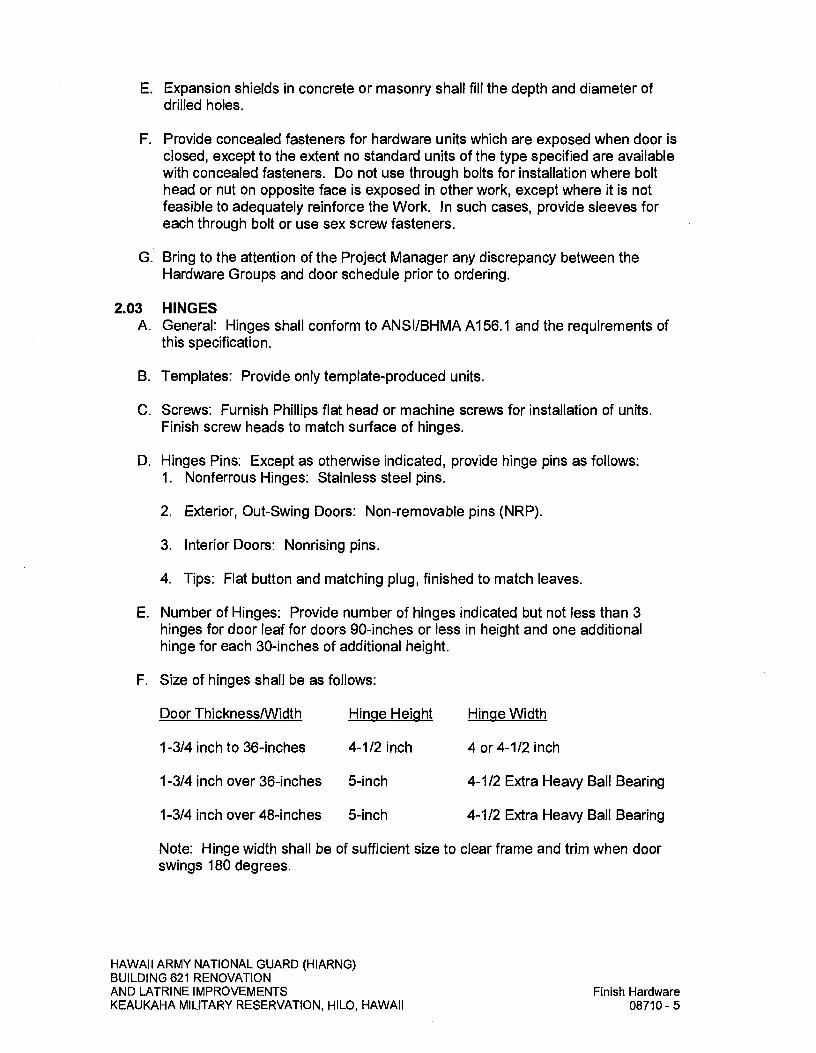
E. Expansion shields in concrete or masonry shall fill the depth and diameter of drilled holes.
F. Provide concealed fasteners for hardware units which are exposed when door is closed, except to the extent no standard units of the type specified are available with concealed fasteners. Do not use through bolts for installation where bolt head or nut on opposite face is exposed in other work, except where it is not feasible to adequately reinforce the Work. In such cases, provide sleeves for each through bolt or use sex screw fasteners.
G. Bring to the attention of the Project Manager any discrepancy between the Hardware Groups and door schedule prior to ordering.
2.03 HINGES A. General: Hinges shall conform to ANSI/BHMA A156.1 and the requirements of
this specification.
B. Templates: Provide only template-produced units.
C. Screws: Furnish Phillips flat head or machine screws for installation of units. Finish screw heads to match surface of hinges.
D. Hinges Pins: Except as otherwise indicated, provide hinge pins as follows: 1. Nonferrous Hinges: Stainless steel pins.
2. Exterior, Out-Swing Doors: Non-removable pins (NRP).
3. Interior Doors: Nonrising pins.
4. Tips: Flat button and matching plug, finished to match leaves.
E. Number of Hinges: Provide number of hinges indicated but not less than 3 hinges for door leaf for doors 90-inches or less in height and one additional hinge for each 30-inches of additional height.
F. Size of hinges shall be as follows:
Door Thickness/Width Hinge Height Hinge Width
1-3/4 inch to 36-inches 4-1/2 inch 4 or 4-1/2 inch
1-3/4 inch over 36-inches 5-inch 4-1/2 Extra Heavy Ball Bearing
1-3/4 inch over 48-inches 5-inch 4-1/2 Extra Heavy Ball Bearing
Note: Hinge width shall be of sufficient size to clear frame and trim when door swings 180 degrees.
HAWAII ARMY NATIONAL GUARD (HIARNG) BUILDING 621 RENOVATION AND LATRINE IMPROVEMENTS
Finish Hardware
KEAUKAHA MILITARY RESERVATION, HILO, HAWAII
08710-5
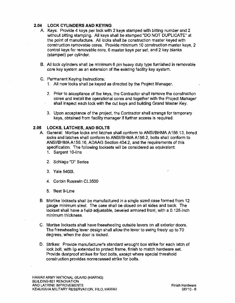
204 LOCK CYLINDERS AND KEYING A. Keys: Provide 4 keys per lock with 2 keys stamped with bitting number and 2
without bitting stamping. All keys shall be stamped "DO NOT DUPLICATE" at the point of manufacture. All locks shall be construction master keyed with construction removable cores. Provide minimum 10 construction master keys, 2 control keys for removable core, 6 master keys per set, and 2 key blanks (stamped) per cylinder.
B. All lock cylinders shall be minimum 6 pin heavy duty type furnished in removable core key system as an extension of the existing facility key system.
C. Permanent Keying Instructions: 1. All new locks shall be keyed as directed by the Project Manager.
2. Prior to acceptance of the keys, the Contractor shall remove the construction cores and install the operational cores and together with the Project Manager shall inspect each lock with the cut keys and building Grand Master Key.
3. Upon acceptance of the project, the Contractor shall arrange for temporary keys, obtained from facility manager if further access is required.
205 LOCKS, LATCHES, AND BOLTS A. General: Mortise locks and latches shall conform to ANSI/BHMA A156.13, bored
locks and latches shall conform to ANSI/BHMA A156.2, bolts shall conform to ANSI/BHMA Al 56.16, ADAAG Section 404.2, and the requirements of this specification. The following locksets will be considered as equivalent: 1. Sargent 10-line
2. Schlage "D" Series
3. Yale 5400L
4. Corbin Russwin CL3500
5. Best 9-Line
B. Mortise locksets shall be manufactured in a single sized case formed from 12 gauge minimum steel. The case shall be closed on all sides and back. The lockset shall have a field-adjustable, beveled armored front, with a 0.125-inch minimum thickness.
C. Mortise locksets shall have freewheeling outside levers on all exterior doors. The freewheeling lever design shall allow the lever to swing freely up to 70 degrees, when the door is locked.
D. Strikes: Provide manufacturer's standard wrought box strike for each latch of lock bolt, with lip extended to protect frame, finish to match hardware set. Provide dustproof strikes for foot bolts, except where special threshold construction provides nonrecessed strike for bolts.
HAWAII ARMY NATIONAL GUARD (HIARNG) BUILDING 621 RENOVATION AND LATRINE IMPROVEMENTS
Finish Hardware
KEAUKAHA MILITARY RESERVATION, HILO, HAWAII
08710-6

E. Lock Throw: 1. Provide 3/4-inch minimum throw of latch and 1-inch minimum for deadbolt.
2. Flush Bolt Heads: Minimum of 1/2-inch diameter rods of brass, bronze or stainless steel, with minimum 12-inches long rod for doors up to 7-feet in height; minimum 42-inches long rod for doors up to 9'-6" in height.
F. Provide locksets, latches, and cylinders equal in all respects to those specified in the Hardware Groups. All thumb turns shall conform to ADAAG Section 309.4.
2.06 CLOSERS AND DOOR CONTROL DEVICES A. General: Closers shall conform to ANSI/BHMA Al 56.4, ADAAG Section 404.2.8
and Section 404.2.9 and the requirements of this specification.
B. Size of Units: Comply with manufacturer's recommendations for size of door control unit, depending upon size of door, exposure to weather, and anticipated frequency of use. Where parallel arm closers are installed, provide closer unit one size larger than recommended for use with standard arms.
C. Maximum effort to operate doors shall not exceed 8.5 pounds for exterior doors and 5 pounds for interior doors, such pull or push effort being applied at right angles to hinged doors. Compensating devices or automatic door operators may be utilized to meet the above standards.
D. Provide parallel arm or regular arm closer as required to mount closer on door face least exposed to public traffic.
E. Closers shall have brass adjustment operating valves for closing speed, latching speed, and backcheck control as a standard feature.
F. Closer covers shall be rectangular, full cover type, high impact non-corrosive, and flame retardant.
G. Closer shall not require removal for adjustments to be made.
2.07 WEATHERSTRIPPING AND DOOR SEALS A. Provide noncorrosive fasteners as recommended by manufacturer for application
indicated.
B. Weatherstrip: ANSI/BHMA Al 56.22, except where furnished as part of an entrance door package or as otherwise indicated, provide continuous weatherstripping at each edge of every exterior door leaf.
C. Replaceable Seal Strips: Provide only those units where resilient or flexible seal strip is easily replaceable and readily available from stocks maintained by manufacturer.
D. Thresholds: Provide all thresholds as indicated on the door schedule conforming to ANSI/BHMA Al 56.21 and ADAAG Section 404.2.5.
HAWAII ARMY NATIONAL GUARD (HIARNG) BUILDING 621 RENOVATION AND LATRINE IMPROVEMENTS
Finish Hardware
KEAUKAI-IA MILITARY RESERVATION, HILO, HAWAII
08710-7
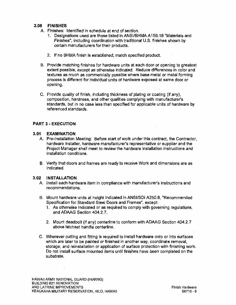
2.08 FINISHES A. Finishes: identified in schedule at end of section.
I. Designations used are those listed in ANSI/BHMA Al 56.18 "Materials and Finishes", including coordination with traditional U.S. finishes shown by certain manufacturers for their products.
2. If no BHMA finish is established, match specified product.
B. Provide matching finishes for hardware units at each door or opening to greatest extent possible, except as otherwise indicated. Reduce differences in color and textures as much as commercially possible where base metal or metal forming process is different for individual units of hardware exposed at same door or opening.
C. Provide quality of finish, including thickness of plating or coating (if any), composition, hardness, and other qualities complying with manufacturer's standards, but in no case less than specified for applicable units of hardware by referenced standards.
PART 3- EXECUTION
3.01 EXAMINATION A. Pre-Installation Meeting: Before start of work under this contract, the Contractor,
hardware installer, hardware manufacturer's representative or supplier and the Project Manager shall meet to review the hardware installation instructions and installation conditions.
B. Verify that doors and frames are ready to receive Work and dimensions are as indicated.
3.02 INSTALLATION A. Install each hardware item in compliance with manufacturer's instructions and
recommendations.
B. Mount hardware units at height indicated in ANSI/SDI A250.8, "Recommended Specification for Standard Steel Doors and Frames", except: I. As otherwise indicated or as required to comply with governing regulations,
and ADAAG Section 404.2.7.
2. Mount deadbolt (if any) centerline to conform with ADAAG Section 404.2.7 above latchset handle centerline.
C. Wherever cutting and fitting is required to install hardware onto or into surfaces which are later to be painted or finished in another way, coordinate removal, storage, and reinstallation or application of surface protection with finishing work. Do not install surface mounted items until finishes have been completed on the substrate.
HAWAII ARMY NATIONAL GUARD (HIARNG) BUILDING 621 RENOVATION AND LATRINE IMPROVEMENTS
Finish Hardware
KEAUKAHA MILITARY RESERVATION, HILO, HAWAII
08710-8

D. Set units level, plumb and true to line and location. Adjust and reinforce attachment substrate as necessary for proper installation and operation.
E. Drill and countersink units which are not factory-prepared for anchorage fasteners. Space fasteners and anchors in accordance with industry standards.
F. Set metal thresholds for exterior doors in full bed of butyl rubber, polyisobutylene mastic sealant, or preformed butyl-polyisobutylene sealant tape as specified under SECTION 07920 - SEALANTS.
G. Fit face of all mortise parts snug and flush.
H. Operating parts shall move freely and smoothly without binding, sticking or excessive clearance.
I. Protect hardware from damage or marring of finish during construction. Use strippable coatings, removable tapes or other accepted means.
J. Ensure that hardware displays no evidence of finish paint after building cleanup with exception of prime coated hardware installed for finish painting. The Contractor may achieve this by sequencing installation, removing after fittings, and reinstalling after painting is completed, providing protection, cleaning original hardware finish, or other accepted means.
K. Latch and Bolt: Install latch and bolt to automatically engage in keeper, whether activated by closer or manual push. In no case shall additional manual pressure be required to engage latch or bolt in keeper.
L. Closers: 1. Do not mount closers on corridor side of door except at exterior doors.
2. Carefully adjust closers to operate noiselessly and evenly and to conform to ADAAG Section 404.2.8 and Section 404.2.9.
3. Have manufacturer's representative regulate closers prior to Project Manager's acceptance of building.
3.03 FIELD QUALITY CONTROL A. Required certified Architectural Hardware Consultant from door hardware
supplier to inspect installation and certify that hardware and installation has been furnished and installed in accordance with manufacturer's instructions and as specified.
B. The manufacturer's representative shall instruct the user's staff on the hardware's maintenance procedures (type of lubricant needed and frequency of maintenance).
HAWAII ARMY NATIONAL GUARD (HIARNG) BUILDING 621 RENOVATION AND LATRINE IMPROVEMENTS
Finish Hardware
KEAUKAHA MILITARY RESERVATION, HILO, HAWAII
08710-9

3.04 ADJUST AND CLEAN A. Adjust and check each operating item of hardware and each door, to ensure
proper operation or function of every unit. Replace items which cannot be adjusted to operate freely and smoothly as intended for application made.
B. Clean adjacent surface soiled by hardware installation.
C. Final Adjustment: Wherever hardware installation is made more than one month prior to acceptance or occupancy of a space or area, return to the Work during the week prior to acceptance or occupancy and make final check and adjustment of all hardware items in such space or area. 1. Clean operating items as necessary to restore proper function and finish of
hardware and doors.
2. Adjust door control devices to compensate for final operation of ventilating equipment and to conform to ADAAG Section 404.2.8 and Section 404.2.9 requirements.
3. Lubricate bearings surface of moving parts and adjust latching and holding devices for proper function.
4. Test keys in every lock for proper operation and conformance with keying system.
3.05 HARDWARE GROUPS
MANUFACTURER LIST
CATEGORY
HINGE AUTO DOOR BOTTOM DOOR SEAL THRESHOLD CONCEALED O.H.STOP DOOR CLOSER LOCKSET MORTISE DEADLOCK KICKPLATE PULL PLATE PUSH PLATE WALL STOP (CONCAVE)
VENDOR NAME
BY McKINNEY PRODUCTS COMPANY BY PEMKO BY PEMKO BY PEMKO BY SARGENT MANUFACTURING COMPANY BY SARGENT MANUFACTURING COMPANY BY SARGENT MANUFACTURING COMPANY BY SARGENT MANUFACTURING COMPANY BY TRIMCO BY TRIMCO BY TRIMCO BY TRIMCO
MFG
MCK PEM PEM PEM SAR SAR SAR SAR TRI TRI TRI TRI
HW GROUP - 001
3.0 EA HINGE
TA2314 4.5X4.5 US26D
MCK 1.0 EA LOCKSET
28-10G24 LL US26D WBX
SAR 1.0 EA WALL STOP (CONCAVE) 1270WV 626/630
TRI
HAWAII ARMY NATIONAL GUARD (HIARNG) BUILDING 621 RENOVATION AND LATRINE IMPROVEMENTS
Finish Hardware
KEAUKAHA MILITARY RESERVATION, HILO, HAWAII
08710-10
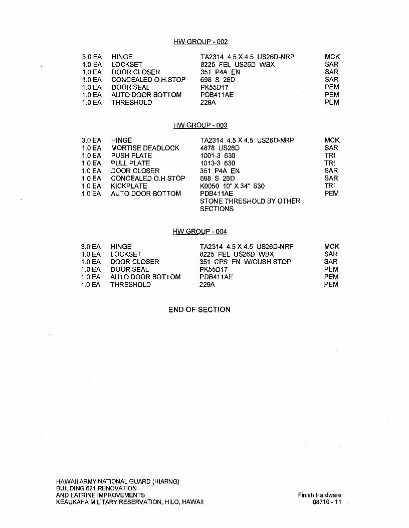
HW GROUP - 002
MCK SAR SAR SAR PEM PEM PEM
3.0 EA 1.0 EA 1.0 EA 1.0 EA 1.0 EA 1.0 EA 1.0 EA
HINGE LOCKSET DOOR CLOSER CONCEALED O.H.STOP DOOR SEAL AUTO DOOR BOTTOM THRESHOLD
TA2314 4.5 X 4.5 US26D-NRP 8225 FEL US26D WBX 351 P4A EN 698 5 26D PK55DI 7 PDB4I IAE 229A
HW GROUP - 003
3.0 EA 1.0 EA 1.0 EA 1.0 EA 1.0 EA 1.0 EA 1.0 EA 1.0 EA
MCK SAR TRI TRI SAR SAR TRI PEM
HINGE MORTISE DEADLOCK PUSH PLATE PULL PLATE DOOR CLOSER CONCEALED O.H.STOP KICKPLATE AUTO DOOR BOTTOM
TA2314 4.5X4.5 U526D-NRP 4878 U526D 1001-3 630 1013-3 630 351 P4A EN 698 5 26D K0050 10"X34" 630 PDB4IIAE STONE THRESHOLD BY OTHER SECTIONS
HW GROUP - 004
MCK SAR SAR PEM PEM PEM
3.0 EA 1.0 EA 1.0 EA 1.0 EA 1.0 EA 1.0 EA
HINGE LOCKSET DOOR CLOSER DOOR SEAL AUTO DOOR BOTTOM THRESHOLD
TA2314 4.5X4.5 US26D-NRP 8225 FEL U526D WBX 351 CPS EN W/CUSH STOP PK55DI 7 PDB4I 1 A 229A
END OF SECTION
HAWAII ARMY NATIONAL GUARD (HIARNG) BUILDING 621 RENOVATION AND LATRINE IMPROVEMENTS
Finish Hardware
KEAUKAHA MILITARY RESERVATION, HILO, HAWAII
08710-11

SECTION 08800 - GLAZING
PART I -GENERAL
1.01 SUMMARY A. Provide all glass and glazing materials to complete all glazing work as shown
and as specified herein.
B. Related Work Described Elsewhere: 1. Blast requirements for glazing systems are provided under SECTION 08810
- BLAST RESISTANT EXTERIOR FACADE SYSTEMS.
2. Framed mirrors at toilet rooms are provided under SECTION 10800-TOILET ACCESSORIES.
1.02 SUBMITTALS A. Submit in accordance with SECTION 01330 - SUBMITTAL PROCEDURES.
B. Manufacturer's Data: Submit copies of manufacturer's product specifications, and instructions for handling, storing, installing, cleaning, and protecting each type of glass and glazing material. Provide data indicating structural and physical characteristics of each type of glass and glazing.
C. Samples: Submit 4 each minimum 4-inch x 4-inch samples of each type and thickness of glass, except for clear monolithic glass, and minimum of 4-inch long samples of each color required, except black, for each type of sealant and gasket exposed to view, for acceptance prior to ordering.
D. Installation Specifications: Submit manufacturer's and referenced glass and glazing manual, etc. for installation of field installed glazing.
1.03 QUALITY ASSURANCE A. Glass Standards: All glass, except as noted otherwise, shall comply with
ASTM C 1036, "Flat Glass". Laminated glass shall comply with ASTM C 1172, "Laminated Architectural Flat Glass".
B. Safety Glass Standard: All glass indicated on the drawings or as required to be safety glass shall meet all the requirements of the "Safety Standard for Architectural Glazing Material", 16 CFR Part 1201 dated January 6, 1977 of the Consumer Product Safety Commission or ANSI Z97.1, "Safety Performance Specifications and Methods of Test for Safety Glazing Materials Used in Buildings", as applicable.
HAWAII ARMY NATIONAL GUARD (HIARNG) BUILDING 621 RENOVATION AND LATRINE IMPROVEMENTS Glazing KEAUKAHA MILITARY RESERVATION, HILO, HAWAII 08800-1

C. Exterior glass thickness and strengths (annealed or heat-treated) shall be as indicated but no less than required to withstand a 105 mph windloading pressure (positive and negative) acting normal to pane of glass as calculated in accordance with the ICC IBC, Exposure C, and ASTM E 1300, "Determining Load Resistance of Glass in Buildings", and ASTM E 330, "Structural Performance of Exterior Windows, Doors, Skylights and Curtain Walls by Uniform Static Air Pressure Difference".
D. Exterior glazing shall conform with Unified Facilities Criteria 4-010-01 and in accordance with SECTION 08810 - BLAST RESISTANT EXTERIOR FACADE SYSTEMS.
E. Limit glass deflection to 1/200 flexure limit of glass with full recovery of glazing materials.
F. Sealants for glazing shall conform to AAMA 800, "Voluntary Specifications and Test Methods for Sealants", and AAMA 850, "Fenestration Sealant Guide Manual".
1.04 DELIVERY, STORAGE, AND HANDLING A. Deliver products to the site in unopened containers, labeled plainly with
manufacturers' names and brands. Store glass and setting materials in safe, dry locations and do not unpack until needed for installation.
B. Comply with manufacturer's instructions for shipping, handling, storing, and protecting glass and glazing materials. Exercise exceptional care to prevent edge damage to glass.
1.05 LABELING A. Each piece of glass shall be of domestic manufacture and label, except as noted
otherwise, showing the name of the manufacturer and the grade or quality thereof. The labels shall be intact before and after installations. When glass is not cut to size by the manufacturer, and is furnished unlabeled from local stock, the Contractor shall submit an affidavit stating the quality, thickness, type, and manufacturer of the glass furnished.
B. All safety glass shall bear a marking as specified in ANSI Z97.1 on each separate glass panel that shall remain visible after installation as required by IBC Section 2403.1 and Section 2406.2 as applicable.
1.06 ENVIRONMENTAL REQUIREMENTS A. Provide ventilation to prevent condensation of moisture on glazing work during
installation. Do not perform glazing work during damp or rainy weather.
HAWAII ARMY NATIONAL GUARD (HIARNG) BUILDING 621 RENOVATION AND LATRINE IMPROVEMENTS Glazing KEAUKAHA MILITARY RESERVATION, HILO, HAWAII 08800-2
PART 2- PRODUCTS
2.01 MATERIALS A. Glass: All glass products shall be of the quality as manufactured by PPG
Industries, Inc., Pilkington LOF, ASG Industries, CE Glass Company, Globe Amerada Glass Co., Guardian Industries, Interpane Glass Co., Sierracin/Sylmar, Viracon, Inc., or accepted equivalent. 1. Laminated Glass (Safety Glass): ASTM C 1172, two pieces of Type I, Class
1, Quality q3 glass laminated together with a clear minimum 0.060-inch thick polyvinyl butyral interlayer under pressure or alternatives such as resin laminates conforming to requirements of 16 CFR 1201 or ASTM C 1172. Total thickness and thickness of interlayer shall be not less than required by SECTION 08810 - BLAST RESISTANT EXTERIOR FACADE SYSTEMS.
B. Glazing Compounds - Sealant for Exterior Glazing: One-Part silicone, medium modulus, Fed. Spec. TT-S-001 543, Class A, non-sag, equal to Dow Corning No. 795, "Silglaze-11 2800", by General Electric Corp., or "Spectrum 2" by Tremco, Inc., Pecora 895NST, or accepted equivalent as recommended by the glass manufacturers.
C. Miscellaneous Glazing Materials: 1. Cleaners, Primers, and Sealers: Of type recommended by sealant
manufacturer.
2. Setting Blocks: Neoprene, EPDM, or 100 percent silicone, 80-90 Shore A durometer hardness as recommended by the glass manufacturer.
3. Spacers: Neoprene or EPDM, 50-60 Shore A durometer hardness.
2.02 FABRICATION A. Fabricate glass to sizes required to comply with wind loads for glazed openings
indicated with edge clearances, bite, and tolerances complying with recommendations of product manufacturer and referenced glazing standard as required to comply with system performance requirements.
PART 3- EXECUTION
3.01 GENERAL A. Perform all glazing, bite on glass, minimum edge and face clearances, glazing
material tolerances, and weep system in strict accordance with applicable provisions of the "Glazing Manual" and "Sealant Manual" published by the Glass Association of North America (GANA).
B. Verify that openings for glazing are correctly sized, within tolerance, and glazing channels or recesses are clean, free of obstructions, and ready to receive glazing.
HAWAII ARMY NATIONAL GUARD (HIARNG) BUILDING 621 RENOVATION AND LATRINE IMPROVEMENTS Glazing KEAUKAHA MILITARY RESERVATION, HILO, HAWAII 08800-3
3.02 INSTALLATION A. Glass shall beset true and tight by skilled glaziers. Glazing compound shall be
neatly and cleanly run with corners carefully made, using putty knife for all work. Glazing stops shall be carefully handled and accurately secured in place.
B. Install setting blocks of proper size in sill rabbet, located one quarter of glass width from each corner, but with edge nearest corner not closer than 6-inches from corner, unless otherwise required. Set blocks in thin course of sealant which is acceptable for heel bead use.
C. Provide spacers inside and out, of correct size and spacing to preserve required face clearances, for glass sizes larger than 50 united inches (length plus height), except where gaskets or glazing tapes with continuous spacer rods are used for glazing. Provide 1/8-inch minimum bite of spacers on glass and use thickness equal to sealant width, except with sealant tape use thickness slightly less than final compressed thickness of tape.
D. Provide edge blocking to comply with requirements of referenced glazing standard, except where otherwise required by glass unit manufacturer.
E. Set units of glass in each series with uniformity of draw, bow, and similar characteristics.
F. Provide compressible filler rods or equivalent back-up material, as recommended by sealant and glass manufacturers, to prevent sealant from extruding into glass channel weep systems and from adhering to joints back surface as well as to control depth of sealant for optimum performance, unless otherwise indicated.
G. Force sealants into glazing channels to eliminate voids and to ensure complete "wetting" or bond of sealant to glass and channel surfaces.
H. Tool exposed surfaces of sealants to provide a substantial "wash" away from glass. Install pressurized tapes and gaskets to protrude slightly out of channel, so as to eliminate dirt and moisture pockets.
I. Where wedge-shaped gaskets are driven into one side of channel to pressurize sealant or gasket on opposite side, provide adequate anchorage to ensure that gasket will not "walk" out when installation is subjected to movement.
J. Miter cut wedge-shaped gaskets at corners and install gaskets in manner recommended by gasket manufacture to prevent pull away at corners; seal corner joints and butt joints with sealant recommended by gasket manufacturer.
K. Glass where secured by glazing stops, shall unless shown on drawings or specified herein, be set in full bed of glazing compound. Then force glazing stop into glazing compound on both sides and strikeoff flush.
L. Glass where required or recommended by glass frame manufacturer shall be set in extruded vinyl or neoprene glazing strips provided by others and shall be installed in strict accordance with manufacturer's instructions.
HAWAII ARMY NATIONAL GUARD (HIARNG) BUILDING 621 RENOVATION AND LATRINE IMPROVEMENTS Glazing KEAUKAHA MILITARY RESERVATION, HILO, HAWAII 08800-4

M. Laminated Glass: Conform to manufacturer's recommendations for edge clearance, type of sealant and tape, and method of installation.
N. Sheet glass shall be cut and set with the visible lines or waves horizontal.
3.03 PROTECTION AND REPLACEMENT A. Glass shall be immediately protected against damage. Glazed openings shall be
identified with suitable warning tapes, cloth or paper flags, or other acceptable method that will not damage glazing or surrounding materials. At completion of work, imperfect glass which cannot be properly cleaned shall be replaced in kind. Broken, chipped, abraded, cracked or otherwise damaged glass must be replaced subject to the acceptance of the Project Manager.
3.04 CLEANING AND WASHING A. At the completion of construction, this Contractor shall clean and wash all of the
glass provided by him, removing all labels, dirt, putty stains, paint, etc., and shall leave the glass perfectly cleaned and polished.
B. Glass to be cleaned according to: 1. GANA Glass Informational Bulletin GANA 01-0300 - Proper Procedures for
Cleaning Architectural Glass Products.
2. GANA Glass Informational Bulletin GANA TD-02-0402 - Heat-Treated Glass Surfaces Are Different.
C. Do not use scrapers or other metal tools to clean glass.
END OF SECTION
HAWAII ARMY NATIONAL GUARD (HIARNG) BUILDING 621 RENOVATION AND LATRINE IMPROVEMENTS Glazing KEAUKAHA MILITARY RESERVATION, H1LO, HAWAII 08800-5
SECTION 08810 - BLAST RESISTANT EXTERIOR FACADE SYSTEMS
PART I - GENERAL
1.01 SUMMARY A. This section includes requirements for blast resistant glazing and door systems.
The following are related sections: 1. SECTION 08110 - STEEL DOORS AND FRAMES
2. SECTION 08800 - GLAZING
1.02 REFERENCES A. ASTM C 1135, "Standard Test Method for Determining Tensile Adhesion
Properties of Structural Sealants".
B. ASTM E 1300, "Standard Practice for Determining Load Resistance of Glass in Buildings".
C. ASTM F 1642, "Standard Test Method for Glazing and Glazing Systems Subject to Airblast Loadings".
D. ASTM F 2247, "Standard Test Method for Metal Doors Used in Blast Resistant Applications (Equivalent Static Load Method)".
E. ASTM F 2248, "Standard Practice for Specifying an Equivalent 3-Second Duration Design Loading for Blast Resistant Glazing Fabricated with Laminated Glass".
F. ASTM F 2912, "Standard Specification for Glazing and Glazing Systems Subject to Airblast Loadings".
G. ASTM F 2927, "Standard Test Method for Door Systems Subject to Airblast Loadings".
H. Unified Facilities Criteria 4-010-011 1 October 2013 (UFC).
I. WinGARD PE version 5.5.1.
1.03 SYSTEM DESCRIPTION A. Design Requirements:
1. Minimum performance requirements for blast resistant windows, exterior glazed doors, and exterior unglazed doors shall meet UFC requirements for either a Very Low Level of Protection, a Low Level of Protection, or a Medium Level of Protection in accordance with the following: a. Low Level of Protection: Assembly Area and attached north/west wing
which houses both YCA and HIARNG personnel.
b. Very Low Level of Protection: Plan west/southwest wing which houses YCA personnel; and the plan east/southeast wing which houses HIARNG personnel.
HAWAII ARMY NATIONAL GUARD (HIARNG) BUILDING 621 RENOVATION AND LATRINE IMPROVEMENTS
Blast Resistant Exterior Facade Systems
KEAUKAHA MILITARY RESERVATION, HILO, HAWAII
08810-1

c. Medium Level of Protection: Exterior vestibule windows and doors, where occur.
2. In conjunction with meeting aesthetic and performance requirements, the Contractor may propose alternate detailing methods for consideration.
B. Performance Requirements: 1. General: Provide design of exterior windows and skylights to meet the
minimum requirements of UFC 4-010-01, Standard 10.
2. Exterior Doors: Glazing must meet the glazing and frame bite provisions of UFC 4-010-01 Standard 10. Door system design in accordance with Standard 12 shall use one of the following methods: a. Equivalent Static Load Testing in accordance with ASTM F 2247 for the
dynamic blast loading listed in paragraph 1.03 B. 5. This method is only applicable to doors required to meet a Very Low Level of Protection and a Low Level of Protection.
b. Blast Testing is accordance with ASTM F 2927 for the dynamic blast loading listed in paragraphs 1.03 B. 5. and 1.03 B. 6. This method is applicable to windows and doors required to meet Very Low, Low and Medium Levels of Protection.
c. Dynamic Design using engineering calculations as outlined in paragraph 1.03 B. 5. This method is applicable to windows and doors required to meet Very Low, Low, and Medium Levels of Protection.
3. Skylights: Skylight glazing shall meet the minimum hazard rating of ASTM F 1642 which allows the glazing to break, but remain in the frame (medium level of protection in UFC 4-010-01 Table 2-1).
4. Window System Design meeting UFC 4-010-01, Standard 10 shall include, but not be limited to, the following: a. Glazing Requirements:
1) Provide laminated glazing with a minimum polyvinyl-butyral (PVB) interlayer thickness of 0.030-inch. For insulated glass units (IGUs), provide laminated glazing with a minimum polyvinyl-butyral (PVB) interlayer thickness of 0.030-inch at the inboard pane.
2) The load resistance of the glazing determined from ASTM E 1300 shall be greater than or equal to the 3-second duration equivalent design load determined from ASTM F 2248, which is listed in this paragraph. Refer to the architectural drawings for window zone reference. a) Zone A: 1.S psi (2l6psf).
b) Zone B: 0.54 psi (78 psf).
c) Zone C: 0.31 psi (45 psf).
HAWAII ARMY NATIONAL GUARD (HIARNG) BUILDING 621 RENOVATION AND LATRINE IMPROVEMENTS
Blast Resistant Exterior Facade Systems
KEAUKAHA MILITARY RESERVATION, HILO, HAWAII
08810-2

d) Zone D: 0. 14 psi (20 psf).
e) Zone E: 1.85 psi (266 psf).
b. Window Framing Requirements: 1) Provide window and skylight frames, mullions, and sashes of
aluminum or steel designed in accordance with ASTM F 2248.
2) Design framing members using strength design with load factors of 1.0 and strength reduction factors of 1.0 for flexure and use typical strength reduction factors for other modes of failure. The moment and shear capacities of framing members shall be designed to resist two (2) times the glazing resistance applied to the framing members only from the tributary area of the window, and the deflection shall be limited to 1/60 of the members' span length between points of structural support. For framing elements which support multiple panes with different glazing capacities, apply the lowest capacity pane over the total tributary area to design the frame element. a) In the case of a punched or ribbon window, the supported edge
length shall be taken as equal to the span of glass, regardless of any intermediate support connections.
b) Intermediate mullions shall be checked for deflection with the supported edge length taken as equal to the longest span of a single glass panel and the deflection shall be calculated based on simple support conditions for that length.
c. Glazing Frame Bite: 1) Glazing must be adhered to the supporting frame with structural
silicone sealant or adhesive glazing tape.
2) Refer to ASTM F 2248 for glazing frame bite requirements for structurally or non-structurally glazed windows, skylights, and glazed doors. At a minimum, the width of the structural silicone bead shall be larger than 3/8 inch of the thickness of the laminated pane. The structural silicone bead shall be no wider than twice the laminated pane thickness. The minimum thickness of the structural silicone bead shall be 3/16 inch. For glazing tape, the width shall be a minimum of twice the laminated pane thickness but no wider than four times the laminated pane thickness. For structurally glazed applications, apply the structural silicone bead to both sides of the glass panel for single pane glazing, but only to the inboard side for insulating glass units.
d. Connection Requirements: 1) The connection design of windows and skylights to adjacent
supporting structural elements, of hardware and fasteners, of glazing stop connections, and of other elements shall be based on strength design with load factors of 1.0 and typical strength reduction factors for all applicable modes of failure.
HAWAII ARMY NATIONAL GUARD (HIARNG) BUILDING 621 RENOVATION AND LATRINE IMPROVEMENTS
Blast Resistant Exterior Facade Systems
KEAUKAHA MILITARY RESERVATION, HILO, HAWAII
08810-3
2) The connection design loads shall be determined in accordance with ASTM F 2248. Connections shall be designed to EITHER: a) Two (2) times the magnitude of the glazing resistance if the ASTM
F 2248 load is greater than half the magnitude of the glazing resistance OR
b) One (I) times the magnitude of the glazing resistance if the ASTM F 2248 load is less than or equal to half the magnitude of the glazing resistance.
5. Alternate Method of Design: As an alternative to the ASTM F 2248 static design approach described in the preceding section, any or all of the glazing, framing members, connections, and supporting structural elements may be designed using dynamic analysis to prove that the element of the window system shall perform equivalent to or better than the hazard rating associated with a low or very low level of protection as defined below. This section also applies for design of solid (unglazed) doors to any level of protection and design of window and door systems to achieve a Medium Level of Protection. a. The dynamic design loading for analysis shall be the appropriate
pressures and impulses from the applicable explosive weights at the actual standoff distances at which the windows are sited. A summary of applicable dynamic design loads and their locations specific to this building's site layout are listed in this section. Refer to the architectural drawings for window zone reference. 1) Zone A: Linearly decaying load with a peak pressure of 53.1 psi and
impulse of 99.2 psi-msec.
2) Zone B: Linearly decaying load with a peak pressure of 10.8 psi and impulse of 45.1 psi-msec.
3) Zone C: Linearly decaying load with a peak pressure of 4.76 psi and impulse of 26.1 psi-msec.
4) Zone D: Linearly decaying load with a peak pressure of 1.80 psi and impulse of 27.0 psi-msec.
5) Zone E: Linearly decaying load with a peak pressure of 79.1 psi and impulse of 117 psi-msec.
b. All elements designed using dynamic analysis shall be analyzed for all applicable dynamic loads. This design load shall be applied over the areas tributary to the element being analyzed. Refer to PDC-TR 10-02.
c. Glazing shall meet the hazard ratings as follows: 1) For a very low level of protection, glazing shall meet the Low Hazard
rating as defined in ASTM F 1642 or H4 Hazard Level as defined in ASTM F 2912 which is defined as the glazing will fracture, come out of the frame, and is likely to be propelled into the building no further than 10 ft from the window at a height no greater than 2 ft above the floor (very low level of protection in UFC 4-010-01 Table 2-1). In WinGARD 5.5.1 a very low level of protection is equivalent to
HAWAII ARMY NATIONAL GUARD (HIARNG) BUILDING 621 RENOVATION AND LATRINE IMPROVEMENTS
Blast Resistant Exterior Facade Systems
KEAUKAHA MILITARY RESERVATION, HILO, HAWAII
08810-4

condition 3b and use the probability of failure value of 500 per 1,000 or less.
2) For a low level of protection, glazing shall meet the Very Low Hazard rating as defined in ASTM F 1642 or H3 Hazard Level as defined in ASTM F 2912 which is defined as the glazing is observed to fracture and is located within I m (40 in.) of its original location (low level of protection in UFC 4-010-01 Table 2-1). In WinGARD 5.5.1 a low level of protection is equivalent to condition 3a and use the probability of failure value of 500 per 1,000 or less.
3) For a medium level of protection, glazing shall meet a Minimal Hazard rating as defined in ASTM F 1642 or H2 as defined in ASTM F 2912.The glazing is observed to fracture, but remains in the frame and results in a minimum hazard consisting of glass dust and slivers. In WinGARD 5.5.1, this is equivalent to GSA Performance Condition 2 and use the probability of failure value of 500 per 1,000 or less.
d. Design frame elements not to exceed the following response limits: 1) For a Very Low Level of Protection:
a) Aluminum: 10 degree rotation and a ductility of 10.
b) Steel: 10 degree rotation.
c) Shear demand-to-capacity ratio of 1.0 for both aluminum and steel.
2) For a Low Level of Protection: a) Aluminum: 6 degree rotation and a ductility of 7.
b) Steel: 6 degree rotation.
c) Shear demand-to-capacity ratio of 1.0 for both aluminum and steel.
3) For a Medium Level of Protection: a) Aluminum: 3 degree rotation and a ductility of 5.
b) Steel: 3 degree rotation.
c) Shear demand-to-capacity ratio of 1.0 for both aluminum and steel.
HAWAII ARMY NATIONAL GUARD (HIARNG) BUILDING 621 RENOVATION AND LATRINE IMPROVEMENTS
Blast Resistant Exterior Facade Systems
KEAUKAHA MILITARY RESERVATION, HILO, HAWAII
08810-5

4) Where support rotations of the primary mullion or transom exceed 3 degrees, analysis is required to verify its ability to develop its plastic capacity without instability. Additional calculations must include, but may not be limited to, analysis of the following: a) Global Performance of Mullion: Analysis shall verify that the
plastic moment of the mullion, acting in a composite manner with its individual components, can be attained under maximum calculated deflections. Fasteners between each component shall be designed for the plastic capacity of the mullion.
b) Lateral Torsional Buckling: Analysis shall verify the ability of the mullion to provide adequate resistance against lateral torsional buckling under maximum calculated deflections.
c) Local Buckling: Analysis hail verify the ability of the mullion and its individual components and connections to provide adequate resistance against localized buckling along the entire load path under maximum calculated deflections.
d) Structural Silicone Stress and Bite: Analysis shall verify the bite and capacity of the silicon to retain the glass under maximum calculated deflection.
e. Door Skin-Plate, Stiffeners, and Related Door Components: 1) Very Low Level of Protection: Door skin-plate, stiffeners and related
door components shall not exceed the following response limits: a) Built-Up (Composite Plate and Stiffeners): 12 degree rotation;
ductility of 20; shear demand-to-capacity ratio of 1.0.
b) Plate (Solid): 12 degree rotation; ductility of 40; shear demand-to-capacity ratio of 1.0.
2) Low Level of Protection: Door skin-plate, stiffeners and related door components shall not exceed the following response limits: a) Built-Up (Composite Plate and Stiffeners): 12 degree rotation;
ductility of 20; shear demand-to-capacity ratio of 1.0.
b) Plate (Solid): 12 degree rotation; ductility of 40; shear demand-to-capacity ratio of 1.0.
3) Medium Level of Protection: Door skin-plate, stiffeners and related door components shall not exceed the following response limits: a) Built-Up (Composite Plate and Stiffeners): 6 degree rotation;
ductility of 10; shear demand-to-capacity ratio of 1.0.
b) Plate (Solid): 6 degree rotation; ductility of 20; shear demand-to-capacity ratio of 1.0.
HAWAII ARMY NATIONAL GUARD (HIARNG) BUILDING 621 RENOVATION AND LATRINE IMPROVEMENTS
Blast Resistant Exterior Facade Systems
KEAUKAHA MILITARY RESERVATION, HILO, HAWAII
08810-6

f. Connection Design: The connection design of doors and windows to adjacent supporting structural elements, of hardware and fasteners, and of other elements shall be based on strength design with load factors of 1.0 and typical strength reduction factors for all applicable modes of failure. Take fastener design strengths from ICC-ES report data. The number of connectors is calculated according to the applicable LRFD design code being used and the reduced nominal strength of the connector using all appropriate strength reduction factors.
6. Testing: As an alternative to these requirements described in paragraphs 1.03 B. 4. and 1.03 B. 5. above, window and skylight systems may be dynamically tested to demonstrate performance equivalent to or better than the glazing hazard rating associated with the appropriate level of protection. The design loading for a dynamic test shall be the appropriate pressure and impulse from the applicable explosive weight at the actual standoff distance at which the window is sited as described in paragraph entitled "Alternate Method of Design" above. Testing shall include the entire window or skylight system, including connections, and shall be in accordance with ASTM F 1642. Test report shall include but not be limited to: a. Minimum of three (3) identical specimens shall be tested for the design
blast load summarized in preceding paragraphs or a higher air-blast load. Those specimens shall be similar to the project window in pane sizes and lay-up, mullion type and sizes, anchor number and system, etc.
b. The structural supporting material used in the test for fastener attachment shall be representative of the field installed condition. Any deviations in field application of the connections or the connected elements from the test must be demonstrated by calculation to provide the required level of protection for the specific application.
c. Standoff distance for the blast test shall be computed and documented in accordance with ASTM F 1642 ANNEX for the design peak pressure and impulse.
d. Minimum of three (3) pressure transducers shall be installed in the frame and one (1) free-field pressure transducer shall be used in the test as specified in ASTM F 1642.
e. Test report shall be performed by an accredited laboratory or signed and sealed by a register Professional Engineer whose qualifications meet or exceed Quality Assurance criteria.
f. Testing shall include the entire window or door system, including connections.
g. Testing of windows shall be in accordance with ASTM F 1642 with hazard ratings in accordance with ASTM F 2912. Testing of door systems shall be in accordance with ASTM F 2247 or with ASTM F 2927. 1) Very Low Level of Protection:
a) Window shall meet a Low Hazard Rating per ASTM F 1642 or H4 per ASTM F 2912.
HAWAII ARMY NATIONAL GUARD (HIARNG) BUILDING 621 RENOVATION AND LATRINE IMPROVEMENTS
Blast Resistant Exterior Facade Systems
KEAUKAHA MILITARY RESERVATION, HILO, HAWAII
08810-7

b) Doors shall meet a Category IV Damage Level in accordance with ASTM F 2247 or ASTM F 2927. Glazing in doors shall meet a H4 Hazard Level per ASTM F 2927.
2) Low Level of Protection: a) Windows shall meet a Very Low Hazard Rating per ASTM F 1642
or H3 Hazard Level/Z3 Specification Level in accordance with ASTM F 2912.
b) Doors shall meet a Category Ill Damage Level in accordance with ASTM F 2247 or ASTM F 2927. Glazing in doors shall meet a H3 Hazard Level per ASTM F 2927.
3) Medium Level of Protection: a) Window shall meet a Minimal Hazard Rating per ASTM F 1642 or
H2 per ASTM F 2912.
b) Doors shall meet a Category II Damage Level in accordance with ASTM F 2247 or ASTM F 2927. Glazing in doors shall meet a H2 Hazard Level per ASTM F 2927.
h. The structural supporting material used in the test for fastener attachment shall be representative of the field installed condition. Any deviations in field application of the connections or the connected elements from the test must be demonstrated by calculation to provide the required level of protection for the specific application.
1.04 SUBMITTALS A. Submit in accordance with SECTION 01330 - SUBMITTAL PROCEDURES.
B. Calculations: 1. Prior to performing engineering calculations submit a description of the
technique(s) that shall be employed to calculate the response of the system to the defined loading.
2. Calculation package is to include a summary sheet briefly outlining the following: a. Evaluation criteria.
b. Calculation assumptions.
c. Table of results by window type/location.
d. Statement of Conformance with specification requirements.
3. Calculation submittal is to be stamped and signed by a registered Professional Engineer whose qualifications meet or exceed the quality assurance in item entitled "QUALITY ASSURANCE" hereinbelow.
HAWAII ARMY NATIONAL GUARD (HIARNG) BUILDING 621 RENOVATION AND LATRINE IMPROVEMENTS
Blast Resistant Exterior Facade Systems
KEAUKAHA MILITARY RESERVATION, HILO, HAWAII
08810-8

4. Submit engineering calculations or experimental testing to show that window response meets specified requirements under static or dynamic design methods.
5. Additionally, illustrate that brittle modes of failure (such as shear and buckling) are avoided. Calculations must include, but may not be limited to, analysis of the following: a. Glass: Determine glass pane performance using an analysis program
such as WinGard (Version 5.5.1 or later), developed by the General Service Administration, If a program other than WinGard is used, it must be approved by the State prior to calculations. WinGard calculations provided in the calculation package are to include the complete text rather than the "concise" text printout.
b. Mullions and Framing Members: Provide a clear load path from the glass to the primary element and supporting analysis which illustrates each component's ability to transfer the design load to the primary element. Analysis of primary element shall illustrate flexural and shear capacity. Supporting analysis that illustrates each component's response to design loading shall be provided. Analysis shall consider both flexural and shear responses. Analysis shall verify the element's ability to develop its plastic flexural capacity without instability. Calculations must include, but may not be limited to, analysis of the following: 1) Global Performance of Mullion: Analysis shall verify that the plastic
moment of the mullion, acting in a composite manner with its individual components, can be attained under maximum calculated deflections.
2) Lateral Torsional Buckling: Analysis shall verify the ability of the mullion to provide adequate resistance against lateral torsional buckling under maximum calculated deflections.
3) Local Buckling: Analysis shall verify the ability of the mullion and its individual components and connections to provide adequate resistance against localized buckling along the entire load path under maximum calculated deflections.
4) Structural Silicone Stress: Analysis shall verify the capacity of the silicone to retain the glass under maximum calculated deflections.
c. Anchorage: Analyze the strength of entire anchorage assembly, including reaction forces shared with the building structure. Provide supplementary steel plates and embeds as required to impart loads onto the structure. Analyze the wall anchor, clip, inserts, fasteners and assemblies, including bolts and stiffeners, and any additional supplementary steel required to transfer the load back to the main structural framing system. Include exact loadings to be transferred to the building structure in the analysis.
HAWAII ARMY NATIONAL GUARD (HIARNG) BUILDING 621 RENOVATION AND LATRINE IMPROVEMENTS
Blast Resistant Exterior Facade Systems
KEAUKAHA MILITARY RESERVATION, HILO, HAWAII
08810-9

d. Mechanical Anchors: Mechanical anchor capacities shall be developed from dynamic testing. An International Code Council (ICC-ES) evaluation report showing testing for dynamic loading (i.e. seismic or blast) is to be submitted with calculations.
e. Supporting Structure: Coordination of the supporting structure interaction shall be the Contractors' responsibility. The Contractor's engineer performing blast calculations for each facade system shall coordinate loading scenarios with the other facade Contractor's engineer providing design for the other exterior facade systems. Forces transmitted from the appropriate window tributary area shall be the design loads from the glazing area.
C. Testing: 1. Test windows are required to be similar to the project windows. Identical
mullion shapes, glass lay-up, window distribution and anchorage system are required between test windows and project windows. Glass panes areas and mullion spans for the project windows are required to be with-in 10 percent of the test windows.
2. Test report package is to include a summary sheet briefly outlining the following: a. Brief description of the test performed.
b. Table of test results by window type/location.
c. Table of comparison between test windows and project windows.
d. Statement of Conformance with ASTM F 1642.
In addition, test report must include all the information required by ASTM F 1642 Section 12.
3. Test report is to be stamped and signed by a registered Professional whose qualifications meet or exceed Quality Assurance criteria and/or certified by an accredited ASTM testing laboratory.
D. Certificates: Engineer's qualifications must meet or exceed the quality assurance in item entitled "QUALITY ASSURANCE" hereinbelow. At a minimum, qualifications must list each project in which the Engineer performed analysis of window systems, the effective start and end dates of performance of the analysis and a reference.
1.05 QUALITY ASSURANCE A. Engineer: Engage an Engineering Professional to perform dynamic analysis of
the Blast Resistant Windows. The Engineer shall have a minimum of 5 years experience in blast resistant design and demonstrable experience designing blast resistant window systems in the past 18 months.
B. Window Bite: The required window system bite must be verified in the field.
HAWAII ARMY NATIONAL GUARD (HIARNG) BUILDING 621 RENOVATION AND LATRINE IMPROVEMENTS
Blast Resistant Exterior Facade Systems
KEAUKAHA MILITARY RESERVATION, HILO, HAWAII
08810-10

C. Installation Orientation: Windows delivered to the construction site are to be clearly labeled as to the proper installation orientation (i.e. laminated pane of glass to be installed as the interior pane).
PART 2- PRODUCTS
2.01 MATERIALS A. Framing Members: Use extruded aluminum alloy sections or continuous
structural steel sections. 1. Yield Strength: Provide supporting references that grade of steel or
aluminum used is capable of achieving calculated ductility ratio.
2. If dynamic analysis is used, the yield strength of framing members may be increased to account for static increase factors and dynamic strain rate effects as follows: a. Structural Steel: For fy = 36 ksi, the yield strength may be increased by a
factor of 1.42. For fy = 42 ksi or greater, the yield strength may be increased by a factor of 1.31.
b. Structural Aluminum: 6063-T6 Alloy - Fy = 25 ksi, the yield strength may be increased by a factor of 1.14. 6061-T6 Alloy - Fy = 35 ksi, the yield strength may be increased by a factor of 1.09.
3. Section Modulus: The plastic section modulus may be used in dynamic design calculations.
4. Built-Up Sections: Design built-up sections using ultimate stress and strain compatibility approaches as defined by industry standards. If a built-up section is analyzed as one unit, full shear stress transfer along the line of contact between the individual sections must be illustrated.
B. Glass Units: 1. Glass-to-Glass Interlayer: Clear polyvinyl butyral (PVB) laminating film/sheet
shall be used on the inner lite of exterior window systems.
2. Window Bite: Glazing must be adhered to frame with structural silicone sealant or adhesive tape per ASTM F 2248.
C. Structural Silicone Sealant: 1. Ultimate Tensile Strength per ASTM C 1135:
a. Minimum 170 psi in tension.
b. Ultimate tensile strength may be increased by a factor of 1.18 to account for dynamic strain rate effects.
2. Safety Factors: Ultimate tension and shear capacities are to be used with a safety factor of 1.0.
3. Apply the structural silicone bead to both sides of the glass panel for single pane glazing, but only to the inboard side for insulating glass units.
HAWAII ARMY NATIONAL GUARD (HIARNG) BUILDING 621 RENOVATION AND LATRINE IMPROVEMENTS
Blast Resistant Exterior Facade Systems
KEAUKAHA MILITARY RESERVATION, HILO, HAWAII
08810-Il
PART 3- EXECUTION
Not used.
END OF SECTION
HAWAII ARMY NATIONAL GUARD (HIARNG) BUILDING 621 RENOVATION AND LATRINE IMPROVEMENTS
Blast Resistant Exterior Facade Systems
KEAUKAHA MILITARY RESERVATION, HILO, HAWAII
08810-12
SECTION 08870 - WINDOW FILM
PART I - GENERAL
1.01 SUMMARY A. Provide window film on the interior face of exterior glazing as indicated.
1.02 SUBMITTALS A. Submit in accordance with SECTION 01330 - SUBMITTAL PROCEDURES.
B. Manufacturer's Data: Submit manufacturer's catalog data for window film.
C. Installation Instructions: Submit copies of the manufacturer's printed instructions for installation, including preparation of substrate and application of window film.
D. Material Safety Data Sheets (MSDS): Submit MSDS for each material used.
E. Samples: Submit 4 each samples of window film for acceptance by the Project Manager.
F. Maintenance Data: Submit copies of manufacturer's printed instructions for cleaning and maintenance.
1.03 QUALITY ASSURANCE A. Completed installation of window film shall be viewed from a distance of 10-feet
against a bright uniform sky or background. The film shall appear uniform in appearance with no visible streaks, banding, thin spots or pin holes.
1.04 DELIVERY, STORAGE, AND HANDLING A. Deliver, store, and handle materials in strict conformance of the manufacturer's
instructions and recommendations.
PART 2- PRODUCTS
2.01 WINDOW FILM A. Manufacturer and Products: Materials shall be as manufactured by 3M Milky
White (Milano), or accepted equivalent as scheduled.
PART 3- EXECUTION
3.01 EXAMINATION A. Verify suitability of surfaces to receive film applications. Do not start installations
until all unsatisfactory conditions have been corrected.
HAWAII ARMY NATIONAL GUARD (HIARNG) BUILDING 621 RENOVATION AND LATRINE IMPROVEMENTS
Window Film
KEAUKAHA MILITARY RESERVATION, HILO, HAWAII
08870-1

3.02 PREPARATION A. Thoroughly wash and razor clean all interior glass surfaces to receive film.
3.03 INSTALLATION A. Film shall be installed per the manufacturer's instruction by an authorized dealer.
Install without air bubbles, creases, visible distortion or joints. Film shall be installed with mounting solution as recommended by the manufacturer and custom cut to the glass with neat, square corners and edges tight to glass perimeter to within 1/16-inch of the window frame.
B. Allow completed installation to dry not less than 30 days. After drying, film shall appear flat when viewed from the room side at a distance of 10-feet and at angles up to 45 degrees looking at a clear uniformly overcast sky.
END OF SECTION
HAWAII ARMY NATIONAL GUARD (HIARNG) BUILDING 621 RENOVATION AND LATRINE IMPROVEMENTS
Window Film
KEAUKAHA MILITARY RESERVATION, HILO, HAWAII
08870-2

DIVISION 9- FINISHES
SECTION 09250 - GYPSUM WALLBOARD
PART I - GENERAL
1.01 SUMMARY A. Complete all gypsum wallboard work as indicated or required by the drawings
and as specified herein. Work shall include, but not be limited to, the following: 1. Gypsum wallboard on metal framing and furring.
2. Metal stud framing for wallboard.
3. Metal ceiling suspension system.
B. Related Work Described Elsewhere: 1. Acoustical sealants are specified in SECTION 07920 - SEALANTS.
2. Access panels are provided under SECTION 08305 - ACCESS DOORS.
1.02 SUBMITTALS A. Submit in accordance with SECTION 01330 - SUBMITTAL PROCEDURES.
B. Manufacturer's Data: Material description and manufacturer's recommended installation procedures for each material.
C. Shop Drawings: Submit shop drawings indicating fabrications and location of control and expansion joints, including plans, elevations, sections, details, and attachment to adjoining work.
D. Material Safety Data Sheets (MSDS): Submit MSDS for each product.
1.03 QUALITY ASSURANCE A. Industry Standard: Comply with applicable requirements of GA-216, "Application
and Finishing of Gypsum Board", GA-214, "Recommended Specification: Levels of Gypsum Board Finish", and GA-201, "Using Gypsum Board for Walls and Ceilings", by the Gypsum Association, except where more detailed or more stringent requirements are indicated, including the recommendations of the manufacturer.
B. Transverse Loading: The non-load bearing metal framing shall be capable of carrying a transverse load of 5 psf without exceeding the allowable stress or a deflection of L/360. Increase stud gauge, decrease stud spacing, or provide hidden from view lateral bracing to comply with these requirements at no additional cost to the State.
HAWAII ARMY NATIONAL GUARD (HIARNG) BUILDING 621 RENOVATION AND LATRINE IMPROVEMENTS
Gypsum Wallboard
KEAUKAHA MILITARY RESERVATION, HILO, HAWAII
09250-1

C. Gypsum Board Terminology: Refer to ASTM C 11, "Terminology Relating to Gypsum and Related Building Materials and Systems", for definition of terms for gypsum board assemblies not defined in this section or in referenced standards.
D. Provide support systems and attachments conforming with AISC 341, "Seismic Provisions for Structural Steel Buildings".
E. Seismic: Brace partitions in accordance with ICC IBC Section 1621, Architectural, Mechanical, and Electrical Component Seismic Design Requirements.
1.04 DELIVERY, STORAGE, AND HANDLING A. Deliver gypsum wallboard materials in sealed containers and bundles, fully
identified with manufacturer's name, brand, type, and grade; store in a dry well ventilated space, protected from the weather, under cover and off the ground. Stack gypsum panels flat to prevent sagging. Joint materials shall be stored in accordance with manufacturer's printed instructions. Damaged or deteriorated materials shall be removed from jobsite.
B. Environmental Limitations: Comply with GA-238, "Guidelines for the Prevention of Mold Growth on Gypsum Board", and ASTM C 840, "Application and Finishing of Gypsum Board", requirements or gypsum board manufacturer's written recommendations, whichever are more stringent.
PART 2 - PRODUCTS
2.01 MATERIALS A. General: Provide panels in maximum lengths and widths available that will
minimize joints and correspond with the applicable support system. All gypsum board shall achieve a score of 10 for mold resistance per ASTM D 3273, "Resistance to Growth of Mold on the Surface of Interior Coatings in an Environmental Chamber".
B. Gypsum Wallboard: ASTM C 1396/C 1396M, "Gypsum Board", 5/8-inch thick, tapered edge type, 48-inches wide, Type "R" regular for all non-rated walls.
C. Water Resistant Board: ASTM C 1396/C 1396M, Type "WR" water-resistant backing board, 5/8-inch thick unless indicated otherwise, with tapered edges, 48-inches wide, unless indicated otherwise (for walls only). Equivalent to ProRoc Moisture and Mold Resistant Gypsum Board by CertainTeed or accepted equivalent.
D. Tile Backer Board: ASTM C 1178/C 1178M, "Coated Glass Mat Water-Resistant Gypsum Backing Panel", glass mat reinforced gypsum backer board, nominal 5/8-inch thick, for hard tile backing, equivalent to DensShield by Georgia Pacific, GlasRoc Tile Backer by CertainTeed, or accepted equivalent. Provide tape and joint compound materials as recommended by manufacturer.
HAWAII ARMY NATIONAL GUARD (HIARNG) BUILDING 621 RENOVATION AND LATRINE IMPROVEMENTS
Gypsum Wallboard
KEAUKAHA MILITARY RESERVATION, HILO, HAWAII
09250-2
E. Wallboard and Sheathing Fasteners: ASTM C 1002, "Steel Self-Piercing Tapping Screws for the Application of Gypsum Panel Products or Metal Plaster Bases to Wood Studs or Steel Studs", standard bugle head self-drilling, self-tapping corrosive-resistant drywall screws. Screws for structural studs shall conform to ASTM C 954, "Steel Drill Screws for the Application of Gypsum Panel Products or Metal Plaster Bases to Steel Studs from 0.033-inch (0.84 mm) to 0.112-inch (2.84 mm) in Thickness".
F. Reinforced Tape and Cement: ASTM C 475/C 475M, "Joint Compound and Joint Tape for Finishing Gypsum Board", materials for treating joints and fastener heads shall be as manufactured or recommended by the Manufacturer of the wallboard used. Provide "setting" type joint compound and fiberglass tape that is unaffected by humidity for water resistant board.
G. Non-Load Bearing Studs: Comply with ASTM C 754, "Installation of Steel Framing Members to Receive Screw-Attached Gypsum Panel Products", for conditions indicated. ASTM C 645, "Nonstructural Steel Framing Members", studs shall be 1-5/8, 2-1/2, 3-5/8, and 6-inch unless indicated otherwise on the drawings. Studs shall be rolled formed channel of 25, 22, and 20 gauge galvanized steel, ASTM A 653/A 653M, "Specification for Steel Sheet, Zinc-Coated (Galvanized) or Zinc-Iron Alloy-Coated (Galvannealed) by the Hot-Dip Process", G60 coating. ProSTUD Drywall Framing System gauges for equivalent structural and composite limiting height studs are acceptable. Provide holes and notches for conduit or electrical wiring. Provide minimum 20 gauge at ceramic tile partitions and partitions with abuse resistant gypsum board.
H. Tracks: Metal floor and ceiling tracks shall be rolled formed channel of gauge electro-zinc plated steel of same gauge as stud with width dimensions suitable to corresponding stud sizes indicated on the drawings.
I. Deep-Leg Deflection Track: ASTM C 645 top runner with 2-inch deep flanges.
J. Furring Channels: ASTM C 645, hat-shaped, 7/8-inch deep, hot-dipped galvanized, 25 gauge.
K. Framing Fasteners: ASTM C 754, except as specified otherwise. Screws used in fire-resistive rated construction shall be of type approved for use by governing building code and fire rating test. For concrete and masonry, provide metal slots with adjustable inserts or adjustable wall furring brackets. Powder actuated fasteners shall be type and size as recommended by the manufacturer of the material being fastened.
L. Ceiling Support Materials and Systems: 1. General: Size ceiling support components to comply with ASTM C 754,
"Installation of Steel Framing Members to Receive Screw-Attached Gypsum Panel Products", unless indicated otherwise.
HAWAII ARMY NATIONAL GUARD (HIARNG) BUILDING 621 RENOVATION AND LATRINE IMPROVEMENTS
Gypsum Wallboard
KEAUKAHA MILITARY RESERVATION, H1LO, HAWAII
09250-3

2. Direct Suspension Systems: Manufacturer's standard zinc-coated or painted steel system of furring runners, furring tees, and accessories designed for concealed support of gypsum drywall ceilings; of proper type for use intended. a. System Manufacturer: Equivalent to one of the following or accepted
equivalent:
Armstrong World Industries, Inc. Chicago Metallic Corp. USG Interiors, Inc.
3. Wire for Hangers and Ties: ASTM A 641/A 641M, "Zinc-Coated (Galvanized) Carbon Steel Wire", Class I zinc coating, soft temper, 8 gauge for hangers supporting up to 12.5 square feet and 6 gauge where supporting up to 16 square feet and 18 gauge for ties.
4. Rod and Strap Hangers: Steel with galvanized finish, sized, and spaced as required for seismic in addition to hanging loads.
M. Wallboard Accessories: ASTM C 1047, "Accessories for Gypsum Wallboard and Gypsum Veneer Base", Vinyl Corp., Plastic Components Inc., Vinyl Tech or accepted equivalent. 1. Standard Corner Bead: Vinyl Corp. Corner Bead CB 125 at all outside
corners of wall, ceiling, and soffit as indicated.
2. Casing Trim: Vinyl Corp. "L" Bead SB 50 or 58, "J" Bead MJB 50 or 58, as applicable, or as indicated.
3. Control Joint: Vinyl Corp. CJV 16.
4. Other Accessories: As indicated or necessary for complete installation.
5. All accessories shall be vinyl, PVC, or accepted equivalent.
N. Joint Treatment Materials: ASTM C 475/C 475M; type recommended by manufacturer for the application indicated, except as otherwise noted. Perforated tape, and joint and topping compound, or "all-purpose" compound.
PART 3- EXECUTION
3.01 EXAMINATION A. Examine substrates to which drywall construction attaches or abuts preset hollow
metal frames and structural framing, with installer present, for compliance with requirements for installation tolerances, existence of mold, and other conditions affecting performance of drywall construction. Do not proceed with installation until unsatisfactory conditions have been corrected.
HAWAII ARMY NATIONAL GUARD (HIARNG) BUILDING 621 RENOVATION AND LATRINE IMPROVEMENTS
Gypsum Wallboard
KEAUKAHA MILITARY RESERVATION, HILO, HAWAII
09250-4

3.02 INSTALLATION A. General: Comply with ASTM C 840, "Application and Finishing of Gypsum
Board", Gypsum Association GA-216, and ASTM C 754 as applicable to the type of substrate and drywall support system indicated.
B. Tolerances: 1. Maximum variation of finish surface from true flatness shall be 1/8-inch in
10-feet in any direction unless specified otherwise.
2. Maximum variation of plumbness of wall shall be 1/8-inch in 10-feet of height.
3. Maximum variation from true position shall be 1/8-inch.
C. Ceiling Support Suspension Systems: 1. Secure hangers to structural support by connecting directly to structure
where possible, otherwise connect to inserts, clips or other anchorage devices or fasteners as indicated. Ensure that structural anchorage provisions have been installed to receive ceiling anchors in a manner that will develop their full strength and at spacing required to support ceiling.
2. Coordinate installation of ceiling suspension systems with installation of overhead structure to ensure that inserts and other provisions for anchorages to building structure have been installed to receive ceiling hangers at spacing required to support ceilings and that hangers will develop their full strength.
3. Install hangers plumb and free from contact with insulation or other objects within ceiling plenum that are not part of supporting structural or ceiling suspension system. Splay hangers only where required to miss obstructions and offset resulting horizontal forces by bracing, countersplaying, or other equally effective means.
4. Where width of ducts and other construction within ceiling plenum produces hanger spacings that interfere with the location of hangers required to support standard suspension system members, install supplemental suspension members and hangers in form of trapezes or equivalent devices. Size supplemental suspension members and hangers to support ceiling loads within performance limits established by referenced standards.
5. Secure hangers to structure, including intermediate framing members, by attaching to inserts, eyescrews, or other devices and fasteners that are secure and appropriate for structure and hanger, and in a manner that will not cause hangers to deteriorate or otherwise fail.
6. Secure wire hangers by looping and wire-tying, either directly to structures or to inserts, eyescrews, or other devices and fasteners that are secure and appropriate for substrate, and in a manner that will not cause them to deteriorate or otherwise fail.
HAWAII ARMY NATIONAL GUARD (HIARNG) BUILDING 621 RENOVATION AND LATRINE IMPROVEMENTS
Gypsum Wallboard
KEAUKAHA MILITARY RESERVATION, HILO, HAWAII
09250-5
7. Sway brace ceiling to conform to the applicable seismic load and uplift, applicable requirements of ASTM E 580/E 580M, "Installation of Ceiling Suspension Systems for Acoustical Tile and Lay-in Panels in Areas Subject to Earthquake Ground Motions", and the manufacturer's recommendations.
8. Space main runners 4-feet on center and space hangers 4-feet on center along runners, except as otherwise shown.
9. Level main runners to a tolerance of 1/8-inch in 12-feet, measured both lengthwise on each runner and transversely between parallel runners.
10. Wire-tie or clip furring members to main runners and to other structural supports as indicated or as recommended by the manufacturer.
11. Direct-Hung Metal Support System: Attach perimeter wall track or angle wherever support system meets vertical surfaces. Mechanically join support members to each other and butt-cut to fit into wall track.
12. Space furring member 16-inches on center, except as otherwise indicated.
13. Install auxiliary framing at termination of drywall work and at openings for light fixtures and similar work, as required for support of both the drywall construction and other work indicated for support thereon.
14. Do not connect or suspend steel framing from ducts, pipes or conduit.
15. Keep hangers and braces 2-inches clear of ducts, pipes, and conduits.
D. Metal Wall and Soffit Framing: 1. Install supplementary framing, blocking, and bracing to support fixtures,
equipment services, heavy trim, grab bars, toilet accessories, furnishings, and similar work which cannot be adequately supported on gypsum board alone to comply with details indicated and with recommendations of gypsum board manufacturer, or if none available, with "Gypsum Construction Handbook" published by United States Gypsum Co.
2. Isolate stud system from transfer of structural loading to system, both horizontally and vertically. Provide slip or cushioned type joints to attain lateral support and avoid axial loading.
3. Install runner tracks at floors, ceilings, and structural walls and columns where gypsum drywall stud system abuts other work, except as otherwise indicated.
4. Extend partition stud system through ceilings and elsewhere as indicated to the structural support or substrate above the ceiling except where indicated to terminate at the ceiling line.
5. Space studs and furring 16-inches on center, except as otherwise indicated.
HAWAII ARMY NATIONAL GUARD (HIARNG) BUILDING 621 RENOVATION AND LATRINE IMPROVEMENTS
Gypsum Wallboard
KEAUKAHA MILITARY RESERVATION, HILO, HAWAII
09250-6

6. Install steel studs so flanges point in the same direction and leading edge or end of each panel can be attached to open (unsupported) edges of stud flanges first.
7. Do not bridge building expansion joints with steel framing or furring. Frame both sides of joints independently.
8. Frame door openings with vertical studs securely attached by screws at each jamb either directly to frames or to jamb anchor clips on door frame in accordance with door manufacturer's recommendations; install runner track sections (for jack studs) at head and secure to jamb studs. Provide runner tracks of same gauge as jamb studs. Space jack studs same as partition studs.
9. Install 20 gauge studs at each jamb for all doors 2-8" wide to 4-feet wide weighing not more than 200 pounds; and for all doors less than 2'-8" wide weighing more than 100 pounds but not more than 200 pounds.
10. Install double 20 gauge studs for single doors up to 4-feet wide, weighing more than 200 pounds but not more than 300 pounds; screw attach web of back-to-back studs direct to jamb anchor clips nested between flange of stud.
11. Frame openings other than door openings in same manner as required for door openings; and install framing below sills of openings to match framing required above door heads.
12. Install each steel framing and furring member so that fastening surface does not vary more than 1/8-inch from plane of faces of adjacent framing.
13. Seal tracks for sound rated partitions with continuous beads of acoustical sealant along each face prior to installation of gypsum board.
E. Gypsum Wallboard, General: 1. Locate exposed end-butt joints as far from center of walls and ceilings as
possible.
2. Install exposed gypsum board with face side out. Do not install imperfect, damaged or damp boards. Butt boards together for a light contact at edges and ends with not more than 1/16-inch open space between boards. Do not force into place.
3. Locate either edge or end joints over supports, except in horizontal applications or where intermediate supports or gypsum board back-blocking is provided behind end joints. Position boards so that both tapered edge joints abut and mill-cut or field-cut end joints abut. Do not place tapered edges against cut edges or ends. Stagger vertical joints over different studs on opposite sides of partitions. Do not make joints other than control joints at corners of framed openings.
HAWAII ARMY NATIONAL GUARD (HIARNG) BUILDING 621 RENOVATION AND LATRINE IMPROVEMENTS
Gypsum Wallboard
KEAUKAHA MILITARY RESERVATION, HILO, HAWAII
09250-7

4. Attach gypsum panels to steel studs so leading edge or end of each panel is attached to open (unsupported) edges of stud flanges first.
5. Attach gypsum board to framing and blocking as required for additional support at openings and cutouts.
6. Cover both faces of stud partition framing with gypsum board in concealed spaces (above ceilings, etc.), except in chase walls which are properly braced internally. Except where concealed application is required for sound, fire, air or smoke ratings, coverage may be accomplished with scraps of not less than 8 square foot area, and may be limited to not less than 75 percent of full coverage.
7. Isolate perimeter of non-load-bearing drywall partitions at structural abutments. Provide 1/4-inch to 3/8-inch space and trim edge with J-type semi-finishing edge trim. Seal joints with acoustical sealant. Do not fasten drywall directly to stud system runner tracks.
8. Space fasteners in gypsum boards in accordance with referenced standards and manufacturer's recommendations, except as otherwise indicated.
9. Tile Backer Board: Install tile backer board in accordance with GA-216, ASTM C 840, manufacturer's instructions, and TCA methods specified in SECTION 09310 - CERAMIC TILE.
F. Methods of Gypsum Wallboard Application: 1. On ceilings, apply gypsum board prior to wall/partition board application, to
greatest extent possible and at right angle to framing, unless otherwise indicated.
2. Install ceiling board panels across framing to minimize the number of abutting end joints and to avoid abutting end joints in the central area of each ceiling. Stagger abutting end joints of adjacent panels not less than one framing member.
3. Single-Layer Application: a. On partitions/walls higher than 8-1 ", apply gypsum board vertically
(parallel), unless otherwise indicated, and provide sheet lengths which will minimize end joints.
b. On partitions/walls 8'-l" or less in height apply gypsum board horizontally (perpendicular); use maximum length sheets possible to minimize end joints.
4. Single-Layer Fastening Method: Apply gypsum boards to supports by fastening with screws, spaced not to exceed 16-inch centers for walls and 12-inch centers for ceilings.
HAWAII ARMY NATIONAL GUARD (HIARNG) BUILDING 621 RENOVATION AND LATRINE IMPROVEMENTS
Gypsum Wallboard
KEAUKAHA MILITARY RESERVATION, HILO, HAWAII
09250-8

G. Installation of Trim Accessories: 1. General: Where feasible, use the same fasteners to anchor trim accessory
flanges as required to fasten gypsum board to the supports. Otherwise, attach trim in accordance with manufacturer's instructions and recommendations.
2. Install corner beads at external corners.
3. Install edge trim whenever edge of gypsum board would otherwise be exposed or semi-exposed. Provide type with face flange to receive joint compound except where semi-finishing type is indicated. Install L-type trim where work is tightly abutted to other work and install special ken-type where other work is kerfed to receive long leg of L-type trim. Install U-type trim where edge is exposed, revealed, gasketed, or sealant-filled (including expansion joints).
4. Install J or LC-type semi-finishing trim where indicated.
5. Install control joints where indicated or necessary in large ceiling and wall expanses per GA-201. Use door header to ceiling or floor to ceiling in long partitions and wall furring runs and from wall to wall in large ceiling areas. Where joint will be conspicuous, obtain acceptance prior to installation.
3.03 DRYWALL FINISHING A. General: Apply treatment at gypsum board joints (both directions), flanges of
trim accessories, penetrations, fasteners heads, surface defects, and elsewhere in accordance with ASTM C 840 and Gypsum Association GA-216 and GA-214 as required to prepare work for decoration. Prefill open joints, rounded or beveled edges, and damaged surfaces using type of compound recommended by manufacturer. 1. Apply joint tape at joints between gypsum boards, except where a trim
accessory is indicated that does not require tape.
2. Apply joint compound in 3 coats (not including prefill of openings in base) and sand between last 2 coats and after last coat. Fastener heads, dents, gouges, and cut-outs shall be filled with joint compound and sanded.
3. Accessories at exposed joints, edges, corners, openings, and similar locations shall be taped, floated with joint compound, and sanded in accordance with manufacturer's instructions and MSDS to produce surfaces ready for gypsum board finishes.
4. Treatment for water-resistant gypsum wallboard shall be as recommended by the gypsum wallboard manufacturer.
B. Finish interior gypsum wallboard by applying the levels of gypsum board finish in accordance with GA-214.
HAWAII ARMY NATIONAL GUARD (HIARNG) BUILDING 621 RENOVATION AND LATRINE IMPROVEMENTS
Gypsum Wallboard
KEAUKAHA MILITARY RESERVATION, HILO, HAWAII
09250-9

3.04 CLEANING AND REPAIRING A. After installation and before painting, correct surface damage and defects.
Leave surface clean and smooth, satisfactory to the painter. No painting shall be done over gypsum board work until the joints are thoroughly dry. Joints and fastenings are to be invisible after painting.
B. Remove drywall materials from electrical boxes, hardware, fixtures, flooring, and similar items and surfaces not intended to receive drywall materials.
END OF SECTION
HAWAII ARMY NATIONAL GUARD (HIARNG) BUILDING 621 RENOVATION AND LATRINE IMPROVEMENTS
Gypsum Wallboard
KEAUKAHA MILITARY RESERVATION, HILO, HAWAII
09250-10
SECTION 09310 - CERAMIC TILE
PART I - GENERAL
1.01 SUMMARY A. Complete all tile and related work as indicated or required by drawings and as
specified herein.
B. Related Work Described Elsewhere: 1. Sealants are specified under SECTION 07920 - SEALANTS.
2. Tile backer board is provided under SECTION 09250 - GYPSUM WALLBOARD.
1.02 SUBMITTALS A. Submit in accordance with SECTION 01330 - SUBMITTAL PROCEDURES.
B. Manufacturer's Data: Submit manufacturer's technical information and installation instructions for selected tile, grout, waterproofing, and sealer materials.
C. Material Safety Data Sheets (MSDS): Submit MSDS for each product.
D. Samples: Submit 4 each samples of various tiles and accessories required to the Project Manager for acceptance and for color and pattern selection. Identify samples as to grade and manufacturer. Submit samples of selected tile in color required, not less than 12-inch square, mounted on plywood or hardboard backing, with selected colored grout.
E. Certificate: Before installation of tile, submit to the Project Manager the Standard Form of Master Grade Certificate signed by the Contractor and Manufacturer, stating grade and kind of tile. Deliver all packages of tile to the job in sealed cartons bearing grade seals in compliance with ANSI A137.1.
F. Warranties: Warranty for a minimum of 2 years against defects resulting from the use of defective or inferior materials, equipment or workmanship.
1.03 DELIVERY, STORAGE, AND HANDLING A. Protect tile, mortar materials, and accessories during delivery, storage, and
construction against moisture, soiling, staining, and physical damage.
B. Handle manufactured materials as recommended by the manufacturer.
HAWAII ARMY NATIONAL GUARD (HIARNG) BUILDING 621 RENOVATION AND LATRINE IMPROVEMENTS
Ceramic Tile
KEAUKAHA MILITARY RESERVATION, HILO, HAWAII
09310-I
PART 2 PRODUCTS
2.01 MATERIALS A. Ceramic Wall and Floor Tiles (PT-#): Standard grade, complying with ANSI
Al 37.1. The Contractor shall submit test reports, from an independent laboratory, indicating conformance of the tile to ANSI A137.1 upon request by the Project Manager. 1. Ceramic Wall Tile and Trims: Dust-pressed, white non-vitreous body with
cushion or semi-cushion edges in sizes and finishes as scheduled.
2. Unglazed Ceramic Floor Tile: Standard quality, dust pressed, machine made porcelain type in size and finishes as scheduled.
3. Trim Units: Provide all trim shapes as detailed and/or as required. External corners shall be rounded convex. Internal vertical corners shall be rounded. Top of wainscot shall be rounded with full bullnose cap. Bottom of wall shall be concave with cove base. Base tile shall be 4-inch high, sanitary coved base unless indicated otherwise. Provide other shapes such as curbs, beads, shoes, round out corners and square in corners, etc. to achieve a neat complete installation.
B. Setting Materials: 1. Cement: Portland cement, ASTM C 150/C 150M, Type I.
2. Sand: ASTM C 144.
3. Hydrated Lime: ASTM C 206, Type S or ASTM C 207, Type S.
4. Latex-Portland Cement Mortar: ANSI Al 18.4, with manufacturer's standard dry polymer additive.
5. Water: Fresh, clean, and potable.
C. Grouting Materials (GRT-#): Colors as indicated or selected by the Project Manager. 1. Epoxy Grout: ANSI Al 18.3.
D. Marble Threshold: ASTM C 503/C 503M, "Marble Dimension Stone", with a minimum abrasion resistance of 12 per ASTM C 1353 or ASTM C 241/C 241M, honed finish, size as indicated or required to conform with ADAAG Section 303 and Section 404.2.5. Bevel edges at 1:2 slope, aligning lower edge of bevel with adjacent floor finish. Limit height of bevel to 1/2-inch or less, and finish bevel to match face of threshold.
E. Factory Blending: For tile exhibiting color variations within the ranges selected during sample submittals, blend tile in factory and package accordingly so that tile units taken from one package show the same range in colors as those taken from other packages and match accepted samples.
HAWAII ARMY NATIONAL GUARD (HIARNG) BUILDING 621 RENOVATION AND LATRINE IMPROVEMENTS
Ceramic Tile
KEAUKAHA MILITARY RESERVATION, HILO, HAWAII
09310-2

2.02 WATERPROOF MEMBRANES A. Floor Waterproofing: Laticrete HydroBan or accepted equivalent.
PART 3- EXECUTION
3.01 EXAMINATION A. Examine substrates and areas where waterproofing and tile will be installed for
compliance with requirements for installation tolerances and other conditions affecting performance of installed tile. 1. Verify that substrates for installing waterproofing and setting tile are firm, dry,
clean, and free from oil or waxy films and curing compounds.
2. Verify that installation of grounds, anchors, recessed frames, electrical and mechanical units of work, and similar items located in or behind tile has been completed before installing tile.
B. Report unsatisfactory conditions to the Contractor for corrective measures; send copy of report to the Project Manager. Do not proceed with installation until unsatisfactory conditions have been corrected. Proceeding with tile work will imply acceptance of the substrate condition by the ceramic tile contractor. Wall substrate must be plumb to within tolerances specified in SECTION 09250 - GYPSUM WALLBOARD and in complete alignment.
C. Do not proceed with floor tile work until waterproofing has been installed and tested.
3.02 INSTALLATION, GENERAL A. ANSI Tile Installation Standard: Comply with parts of ANSI 108 series of tile
installation standards included under "American National Standard Specifications for the Installation of Ceramic Tile" that apply to type of setting and grouting materials and methods indicated.
B. TCNA Installation Guidelines: TCNA "Handbook for Ceramic Tile Installation"; comply with TCNA installation methods indicated.
C. Extend tile work into recesses and under or behind equipment and fixtures to form a complete covering without interruptions except as otherwise shown. Terminate work neatly at obstructions, edges, and corners without disrupting pattern or joint alignments.
D. Accurately form intersections and returns. Perform cutting and drilling of tile without marring visible surfaces. Carefully grind cut edges of tile abutting trim, finish, or built-in items for straight aligned joints. Fit tile closely to electrical outlets, piping, fixtures, and other penetrations so that plates, collars, or covers overlap tile.
HAWAII ARMY NATIONAL GUARD (HIARNG) BUILDING 621 RENOVATION AND LATRINE IMPROVEMENTS
Ceramic Tile
KEAUKAHA MILITARY RESERVATION, HILO, HAWAII
09310-3

E. Jointing Pattern: Unless otherwise shown, lay tile in grid pattern. Align joints when adjoining tiles on floor, base, walls, and trim are same size. Lay out tile work and center tile fields in both directions in each space or on each wall area. Adjust to minimize tile cutting. Provide uniform joint widths unless otherwise shown. For tile mounted in sheets, make joints between tile sheets same width as joints within tile sheets so that extent of each sheet is not apparent in finished work.
F. Expansion Joints: Locate expansion joints and other sealant-filled joints, including control, contraction, and isolation joints, where indicated during installation of setting materials, mortar beds, and tile. Do not saw cut joints after installation of tiles. Locate joints in tile surfaces directly above joints in concrete substrates. Expansion joints shall conform to TCNA Installation Method EJI7I.
G. Grout: Grouts shall comply with ANSI A108.10. Epoxy grout shall conform to ANSI A108.6.
H. Allow tiles to set a minimum of 48 hours prior to grouting. The grout shall be forced into the joints to the full depth. Take special care not to scratch glazed tile during this operation. Remove surplus grout before it has hardened and leave the face of the tile clean. Keep expansion and control joints free of grout.
I. Sound tiles after setting to ensure proper bonding. Hollow sounding tiles shall be replaced.
J. Curing Floors: Apply reinforced kraft paper over floor as soon as pointing or grouting is completed. Lap the paper not less than 6-inches and leave in place for 3 full days. Cure in accordance with applicable ANSI installation procedure.
K. Waterproof Membrane: Install waterproof membrane as recommended by the manufacturer at slabs and surfaces as indicated or scheduled by TCNA installation method.
3.03 FLOOR INSTALLATION METHODS A. Install types of tile to comply with requirements indicated below for setting bed
methods, TCNA installation methods related to types of subfloor construction, and grout types: 1. Portland Cement Mortar Bed: ANSI Al 08.1 B or C (Thickset).
a. Bond Coat: Portland cement paste or dust coat on plastic bed or thin-set Latex-Portland cement mortar on cured bed, ANSI Al 08.5, at Contractor's option.
b. Concrete Slab at Grade: TCNA Installation Method Fl 12 and TCNA Installation Method F121 where waterproof membrane is required.
2. Latex Portland Cement Mortar: ANSI A108.5 (Thinset). a. Concrete Slab at Non-Depressed Slabs: TCNA Installation Method Fl 13
where no membrane indicated.
3. Grout: Epoxy.
HAWAII ARMY NATIONAL GUARD (HIARNG) BUILDING 621 RENOVATION AND LATRINE IMPROVEMENTS
Ceramic Tile
KEAUKAHA MILITARY RESERVATION, HILO, HAWAII
09310-4

B. Marble Thresholds: Install marble thresholds at locations indicated; set in same type of setting bed as abutting field tile unless otherwise indicated. Threshold installation shall comply with ADAAG Section 404.2.5. Clean as recommended by the manufacturer.
3.04 WALL TILE INSTALLATION METHODS A. Install types of tile designated for wall application to comply with requirements
indicated below for setting-bed methods, TCNA installation methods related to subsurface wall conditions, and grout types: 1. Latex-Portland Cement Mortar: ANSI Al 08.5.
a. Tile Backer Board: TCNA Installation Method W245.
b. Concrete Masonry: TCNA Installation Method W202.
2. Grout: Epoxy.
3.05 CLEANING AND PROTECTION A. Cleaning: Upon completion of placement and grouting, clean all tile surfaces so
they are free of foreign matter. 1. Remove grout residue from tile as soon as possible. Clean in accordance
with applicable ANSI installation procedure.
2. Unglazed tile may be cleaned with acid solutions only when permitted by tile and grout manufacturer's printed instructions, but no sooner than 14 days after installation. Protect metal surfaces, cast iron, and vitreous plumbing fixtures from effects of acid cleaning. Flush surface with clean water before and after cleaning.
3. Remove temporary protective coating by method recommended by coating manufacturer that is acceptable to tile and grout manufacturer. Trap and remove coating to prevent it from clogging drains.
B. Finished Tile Work: Leave finished installation clean and free of cracked, chipped, broken, unbonded, and otherwise defective tile work.
C. Provide final protection and maintain conditions in a manner acceptable to manufacturer and installer that ensures that tile is without damage or deterioration at time of Project Acceptance. 1. When recommended by tile manufacturer, apply a protective coat of neutral
protective cleaner to completed tile walls and floors. Protect installed tile work with kraft paper or other heavy covering during construction period to prevent staining, damage, and wear.
2. Prohibit foot and wheel traffic from tiled floors for at least 7 days after grouting is completed.
3. Protect tiled corners and external angles with board corner strips in areas used as passageways by workers.
HAWAII ARMY NATIONAL GUARD (HIARNG) BUILDING 621 RENOVATION AND LATRINE IMPROVEMENTS
Ceramic Tile
KEAUKAHA MILITARY RESERVATION, HILO, HAWAII
09310-5

D. Before final inspection, remove protective coverings and rinse neutral cleaner from tile surfaces.
END OF SECTION
HAWAII ARMY NATIONAL GUARD (HIARNG) BUILDING 621 RENOVATION AND LATRINE IMPROVEMENTS
Ceramic Tile
KEAUKAHA MILITARY RESERVATION, HILO, HAWAII
09310-6
SECTION 09510 - ACOUSTICAL CEILING
PART I - GENERAL
1.01 SUMMARY A. Provide suspended lay-in acoustical ceiling systems as indicated and herein
specified.
B. Related Work Specified Elsewhere: 1. Acoustical sealants are specified in SECTION 07920 - SEALANTS.
2. Coordinate location of all mechanical items with DIVISION 15 - MECHANICAL.
3. Coordinate location of all electrical items with DIVISION 16- ELECTRICAL.
102 SUBMITTALS A. Submit in accordance with SECTION 01330 - SUBMITTAL PROCEDURES.
B. Manufacturer's Data: Submit manufacturer's technical product data and installation instructions for suspension system and lay-in panels substantiating that all products comply with project requirements.
C. Shop Drawings: Submit shop drawings which clearly show all components of the systems to be installed at this project. Include suspension system, furring, jointing, method of anchoring and fastening, and locations of mechanical and electrical features. Jointing diagrams shall show typical arrangement of the panels in each space, including the terminations at margins of ceilings and at intersections with vertical surfaces. Include typical details of the following: 1. Intermediate framing for hanger supports that fall between structural framing
members.
2. Hanger fastenings at structural framing members and at main runners.
3. Acoustical-unit support at ceiling penetrations.
4. Splicing method for main and cross runners.
5. Seismic restraint system.
D. Samples: Submit 4 samples of each type of acoustical unit, edge molding, and suspension runner.
E. Maintenance Instructions: Submit manufacturer's maintenance instructions for acoustical ceilings.
HAWAII ARMY NATIONAL GUARD (HIARNG) BUILDING 621 RENOVATION AND LATRINE IMPROVEMENTS
Acoustical Ceiling
KEAUKAHA MILITARY RESERVATION, HILO, HAWAII
09510-1
F. Receipt of Delivery: Three copies of the receipt signed by the user's representative, attesting to delivery of extra lay-in panels as required under item entitled "EXTRA LAY-IN PANELS" hereinbelow.
1.03 DESIGN CRITERIA FOR CEILING SYSTEMS A. Suspended Ceiling Attenuation Class: The ceiling attenuation class (ceiling CAC
range) of the ceiling system shall be as specified when determined in accordance with ASTM E 1414, "Airborne Sound Attenuation Between Rooms Sharing a Common Ceiling Plenum". Test ceiling shall be continuous at the partition and shall be assembled in the suspension system in the same manner that the ceiling will be installed on the project.
B. Ceiling Sound Absorption: Determine the NRC in accordance with ASTM C 423, "Test Method for Sound Absorption and Sound Absorption Coefficients by the Reverberation Room Method".
C. Light Reflectance: Determine light reflectance factor in accordance with ASTM E 1477, "Luminous Reflectance Factor of Acoustical Materials by Use of Integrating-Sphere Reflectometers", test method.
D. Seismic: Install ceiling system in accordance with ASTM E 580/E 580M, "Practice for Installation of Ceiling Suspension Systems for Acoustical Tile and Lay-in Panels in Areas Subject to Earthquake Ground Motions", and ICC IBC Section 1613, Earthquake Loads.
1.04 DELIVERY, STORAGE, AND HANDLING A. Deliver acoustical units in the manufacturer's original unopened containers with
brand name and type clearly marked. Handle materials carefully and store them under cover in dry, watertight enclosures.
B. Handle manufactured materials as recommended by the manufacturer.
1.05 ENVIRONMENTAL CONDITIONS A. For 24 hours before, during, and 24 hours after installation of acoustical units,
maintain temperature and relative humidity at typical in-service conditions. Interior finish work such as concrete work shall be completed and dry before installation. Mechanical, electrical, and other work above the ceiling line shall be completed and accepted prior to the start of acoustical ceiling installation.
PART 2 PRODUCTS
2.01 MATERIALS A. Acoustical Ceiling Tile Units: ASTM E 1264, "Classification for Acoustical Ceiling
Products", and the requirements for each type. For convenience and to establish standards of quality and design, the following list indicates items manufactured by Armstrong World Industries, Inc. Equivalent products, accepted by the Project Manager, of the following manufacturers will be accepted: 1. USG Interiors Inc.
HAWAII ARMY NATIONAL GUARD (HIARNG) BUILDING 621 RENOVATION AND LATRINE IMPROVEMENTS
Acoustical Ceiling
KEAUKAHA MILITARY RESERVATION, HILO, HAWAII
09510-2

2. Celotex Corporation
The products of other manufacturers are acceptable provided they meet or exceed the materials and construction requirements as specified.
B. Composition Lay-In Panels (ACT-1): 1. Type: Type Ill (Non-asbestos mineral composition) with factory-applied
standard white washable painted finish.
2. Form: 2.
3. Class: A, flame spread 25 or less.
4. Pattern: CE.
5. Noise Reduction Coefficient (NRC) Grade: Minimum 0.55.
6. Ceiling Attenuation Class (CAC): Minimum 35.
7. Light Reflectance (LR) Coefficient: LR-0.84 or greater.
8. Nominal Size: 24 x 48-inches.
9. Edge Detail: Square lay-in.
10. Design: Armstrong Fine Fissured, No. 1729 or accepted equivalent.
2.02 SUSPENSION SYSTEM A. Suspension System: ASTM C 635/C 635M, "Manufacture, Performance, and
Testing of Metal Suspension Systems for Acoustical Tile and Lay-in Panel Ceilings", and the following requirements: I. Type: Exposed grid, 15/16-inch standard width. Provide grid for high
humidity exposure.
2. Structural Classification: Heavy duty for main runners as required by Seismic Load per ICC IBC.
3. Finish: Surfaces exposed to view shall be of uniform width and shall be aluminum or galvanized steel with factory applied white baked enamel finish in colors to match ceiling tile. Zinc coated steel shall receive a phosphate treatment prior to painting.
4. Trim: Aluminum prefinished trim channel, Armstrong Axiom Classic Trim Channel, 10-inch or accepted equivalent.
5. Accessories: Provide manufacturer's standard wall or edge moldings.
B. Hanger Wires: ASTM A 641/A 641 M, "Zinc-Coated (Galvanized) Carbon Steel Wire", Class 1, 12 gauge, galvanized steel.
HAWAII ARMY NATIONAL GUARD (HIARNG) BUILDING 621 RENOVATION AND LATRINE IMPROVEMENTS
Acoustical Ceiling
KEAUKAHA MILITARY RESERVATION, HILO, HAWAII
09510-3

C. Fasteners: Rust-resistant of the type recommended by the manufacturer. Size fasteners for 5 times design load indicated in ASTM C 635/C 635M, Table 1, Direct Hung, unless indicated otherwise.
PART 3- EXECUTION
3.01 PREPARATION A. The Acoustical Contractor shall be responsible for the examination and
acceptance of all surfaces and conditions affecting the installation of his work. Start of this work shall constitute acceptance of all work conditions. Unsatisfactory conditions shall be reported to the Project Manager so that corrective measures can be taken.
3.02 INSTALLATION A. General: Installation shall conform to the manufacturer's directions for the
suspension system and lay-in panels used and to the layout shown on the drawings for the size grid to be installed.
B. Suspended Ceilings: ASTM C 636/C 636M, "Practice for Installation of Metal Ceiling Suspension Systems for Acoustical Tile and Lay-in Panels", and ASTM E 580/E 580M. 1. Hangers: Space hangers 4-feet on centers each direction. Lay hangers out
for each individual room or space. Install additional hangers where required to support framing around beams, ducts, columns, grilles, and other penetrations through the ceiling.
2. Suspension Members: Keep main runners and carrying channels clear of abutting walls and partitions. Provide at least two main runners for each ceiling span.
3. Acoustical Units: Edges of ceiling tiles shall be in close contact with metal supports and in true alignment. Arrange units so that units less than 1/2 width are minimized. Units in exposed-grid system shall be held in place with manufacturer's standard hold-down clips, at units weighing less than I psf or for vertical panels.
4. Wall or Edge Molding: Install wall molding at intersection of suspended ceiling and vertical surfaces. Miter corners where wall moldings intersect or install corner caps.
5. Tolerance: Ceilings shall be flat and level within 1/8-inch in 10-feet.
6. Sealing: Apply a continuous ribbon of acoustical sealant on vertical leg of wall or edge mouldings.
7. Where cut edges of lay-in panels are exposed or panel face is scratched, paint edges or face to match standard facing with coating as recommended by the manufacturer.
HAWAII ARMY NATIONAL GUARD (HIARNG) BUILDING 621 RENOVATION AND LATRINE IMPROVEMENTS
Acoustical Ceiling
KEAUKAHA MILITARY RESERVATION, HILO, HAWAII
09510-4

3.03 CLEANING AND REJECTION A. The Contractor shall exercise all necessary precautions to avoid damaging or
soiling the units. All damaged units shall be replaced with new units by the Contractor.
B. Following defects shall be cause for rejection or replacement of tiles or panels by Contractor: 1. Crooked or open joints.
2. Soiled tiles or panels not cleaned to original condition.
3. Fractures, cracks or corner chips.
4. Color variation.
5. Loose or fallen tiles and panels.
6. Warped tiles and panels.
7. Units damaged from leaking roof.
3.04 EXTRA LAY-IN PANELS A. The Contractor shall provide a minimum of 1 percent extra lay-in panels in
labeled full original manufacturer's containers for each type and color used for ceilings to the facility upon completion of the project. Materials shall be in the same lot number used in the project.
END OF SECTION
HAWAII ARMY NATIONAL GUARD (HIARNG) BUILDING 621 RENOVATION AND LATRINE IMPROVEMENTS
Acoustical Ceiling
KEAUKAHA MILITARY RESERVATION, HILO, HAWAII
09510-5

SECTION 09651 - RESILIENT BASE
PART I - GENERAL
1.01 SUMMARY A. Provide resilient base where scheduled and as specified herein.
1.02 SUBMITTALS A. Submit in accordance with SECTION 01330 SUBMITTAL PROCEDURES.
B. Manufacturer's Data: Submit manufacturer's product data for base and adhesive, including installation instructions.
C. Samples: Submit 4 samples of bases shall be submitted to the Project Manager for color selection.
D. Material Safety Data Sheets (MSDS): Submit MSDS for each product.
1.03 DELIVERY, STORAGE, AND HANDLING A. Materials shall be delivered to the jobsite in original unopened containers marked
with grade and manufacturer's brand name. Handle and store materials carefully in accordance with manufacturer's instructions.
PART 2- PRODUCTS
2.01 MATERIALS A. Resilient Wall Base (RB-#): Resilient base shall conform to ASTM F 18611
"Resilient Wall Base", Type TS or TP, rubber, Group I or 2, 4-inch high, top-set type, 1/8-inch thick, with a smooth exposed surface and textured bonding surface on its unexposed face. Provide Style B, cove type. Provide preformed outside corners. The rubber material shall be free from offensive odor and its color shall be uniform throughout the thickness of the base. Base shall be equivalent to Burke Mercer Flooring Products Cove Base, Johnsonite, Roppe, Mannington, Azrock, Armstrong, Tarkett, or accepted equivalent.
B. Adhesives: Base adhesive shall be water-based, rubber-resin formula, as recommended by the manufacturer for the specific materials used. Material shall be beige or white, solvent free with zero VOC content, low odor, no ammonia, and non-flammable in wet state. Do not use adhesive not intended for its purpose. VOC content of adhesives shall be less than the current VOC content limits of the South Coast Air Quality Management District Rule 1168, "Adhesive and Sealant Application".
HAWAII ARMY NATIONAL GUARD (HIARNG) BUILDING 621 RENOVATION AND LATRINE IMPROVEMENTS
Resilient Base
KEAUKAHA MILITARY RESERVATION, HILO, HAWAII
09651-1

PART 3 EXECUTION
3.01 INSTALLATION OF MATERIALS A. Resilient base shall continue behind removable and/or portable cabinets, cases,
etc. Installation shall not begin until the work of other trades, including painting, has been completed.
B. All work shall be done by experienced tradesmen in strict accordance with recommended specifications of the respective manufacturer. Where not contrary to manufacturer's recommendations, adhesive shall be applied with a notched trowel in a thin and even coat.
C. Resilient base shall be applied onto thoroughly-dried walls with cove base adhesive only. Because of the thermoplastic character of base, care shall be taken not to stretch it during installation since it will shrink and leave a gap at joints. The top and bottom edges shall be in firm contact with the wall and floor. Pre-molded interior and exterior corners shall be used unless otherwise accepted by the Project Manager. If corners are formed on the job, the wrap around from the corner shall be not less than 12-inches long. Otherwise, the resilient base shall be continuous around the corners. On masonry and similar irregular substrates, fill voids along top edge of resilient base with manufacturer's recommended adhesive filler material.
3.02 CLEANING AND PROTECTION A. Spots of adhesive shall be removed immediately as work progresses.
Contractor shall be responsible for protecting the resilient bases until acceptance of the project. Clean bases, but do not polish them.
END OF SECTION
HAWAII ARMY NATIONAL GUARD (HIARNG) BUILDING 621 RENOVATION AND LATRINE IMPROVEMENTS
Resilient Base
KEAUKAHA MILITARY RESERVATION, HILO, HAWAII
09651-2
SECTION 09900 PAINTING
PART I GENERAL
1.01 SUMMARY A. The work includes painting and finishing of exterior and interior items and
surfaces throughout the project, whether scheduled or not, except as otherwise indicated. Painting shall include new work and existing new surfaces made bare or damaged during construction and existing surfaces as scheduled. Surface preparation, priming, and coats of paint specified are in addition to shop-priming and surface treatment specified under other sections of the work and is included in this section.
B. The work includes field painting of exposed bare and covered pipes and conduits (including color coding), and of hangers, exposed steel and iron work, and primed metal surfaces of equipment installed under the electrical work, such as junction boxes, raceways, and cabinets, except as otherwise indicated.
C. "Paint" as used herein means all coating systems materials, including primers, enamels, sealers, stain, varnish, and fillers, and other applied materials whether used as prime, intermediate, or finish coats, except as specifically noted herein.
D. Paint all exposed surfaces whether or not colors are designated in "schedules". Where items or surfaces are not specifically mentioned, paint these the same as adjacent similar materials or areas. If color or finish is not designated, the Project Manager will select these from standard colors available for the materials systems specified.
1.02 PAINTING NOT INCLUDED A. The following categories of work are not included as part of the field-applied
finish work, or are included in other sections of these specifications. 1. Shop Priming: Unless otherwise specified, shop priming of ferrous metal
items is included under the various sections for miscellaneous metal, hollow metal work, and similar items. Also, for fabricated components such as shop-fabricated or factory-built mechanical and electrical equipment or accessories.
2. Mechanical and Electrical Work: The prime coat for mechanical and electrical work is specified in DIVISION 15- MECHANICAL and DIVISION 16 - ELECTRICAL, respectively. Finish coats are as specified herein.
3. Pre-Finished Items: Unless otherwise indicated, do not include painting when factory-finishing or installer finishing is specified for such items as (but not limited to) solid phenolic, plastic laminate, acoustic materials, high performance organic coated metal, and finished mechanical and electrical equipment, including light fixtures, switchgear, and distribution cabinets.
HAWAII ARMY NATIONAL GUARD (HIARNG) BUILDING 621 RENOVATION AND LATRINE IMPROVEMENTS Painting KEAUKAHA MILITARY RESERVATION, HILO, HAWAII 09900-1
4. Concealed Surfaces (Present and Future): Unless otherwise indicated, painting is not required on surfaces such as walls or ceilings in concealed areas and generally inaccessible areas, furred areas, and pipe spaces.
5. Finished Metal Surfaces: Metal surfaces of anodized aluminum, stainless steel, chromium plate, and similar finished materials will not require finish painting, unless otherwise indicated.
6. Labels: Do not paint over any code-required labels, such as Underwriters' Laboratories, or any equipment identification, performance rating, name, or nomenclature plates.
1.03 SUBMITTALS A. Submit in accordance with SECTION 01330 - SUBMITTAL PROCEDURES.
B. Schedule of Finishes: Submit sets of the proposed painting finish schedule to the Project Manager for acceptance. The schedule shall indicate the wet film thickness (mils) at which the proposed paints/coatings will be applied that are necessary to achieve the final dry film thickness indicated on the Schedule of Finishes under item entitled "SCHEDULE OF FINISHES" hereinbelow.
C. Color Samples: Submit the following to the Project Manager for acceptance. 1. Four sets of each color finish sample.
2. After the color finish sample has been accepted, one set of color finish samples painted onto 8-1/2 inch x 11-inch cardboard shall be submitted. The cardboard shall be divided into three horizontal strips and painted as follows: a. Prime 3 strips.
b. First coat bottom 2 strips.
c. Second coat bottom strip.
D. Schedule of Operations: Before work on the project is commenced, submit complete sets of a work schedule showing Contractor's sequence of operations and dates.
E. Warranty: Submit warranty as stipulated in item entitled "WARRANTY" hereinbelow.
F. Certifications: Submit copies of asbestos-free, lead-free, zinc-chromate-free, strontium-chromate-free, cadmium-free, and mercury free paint certificates.
G. Manufacturer's Product Data Sheets: Submit copies of the Manufacturer's Product Data Sheets for the primers, paints, coatings, solvents, sealing and patching materials, sealants and caulking, and other materials being used. Data sheets shall indicate thinning and mixing instructions, required film thickness (mil) and application instructions.
HAWAII ARMY NATIONAL GUARD (HIARNG) BUILDING 621 RENOVATION AND LATRINE IMPROVEMENTS Painting KEAUKAHA MILITARY RESERVATION, H1LO, HAWAII 09900-2

H. Manufacturer's Material Safety Data Sheets (MSDS): Submit copies of the Manufacturer's Material Safety Data Sheets for coatings, solvents, and other hazardous materials.
I. Receipt of Delivery: Submit copies of the receipt signed by the user's representative, attesting to delivery of extra paint as required under paragraph entitled "Extra Paint" hereinbelow.
J. Comprehensive Spray Plan: Where the Contractor proposes to employ airless spraying, submit a Comprehensive Spray Plan, including the following information for acceptance: 1. Documentation that the individual spray applicator(s) on the project have
completed an accepted "Spray Applicator Certification Program".
2. The overspray protection methods proposed.
3. The spray application instructions and recommendations of the paint manufacturer he proposes to use.
K. Certificate of Public Liability and Property Damage Insurance
1.04 ANALYZING AND TESTING A. All paints and their applied thickness shall be subject to testing whenever the
Project Manager deems necessary to determine conformation to the requirements of these specifications. Should testing by a laboratory be required, the laboratory shall be selected by the State and the cost of testing shall be borne by the Contractor. However, should test results show that the paint is in compliance with this specifications, the cost will be borne by the State.
B. All rejected material shall be removed from the job site immediately. Surfaces painted with the rejected material shall be redone at no additional cost to the State.
C. Where the required paint thickness is deficient, the affected surface(s) shall be recoated as necessary to provide the required paint thickness at no additional cost to the State.
1.05 QUALITY ASSURANCE A. Painting Terminology: Refer to ASTM D 16, "Standard Terminology for Paint,
Related Coatings, Materials, and Applications".
HAWAII ARMY NATIONAL GUARD (HIARNG) BUILDING 621 RENOVATION AND LATRINE IMPROVEMENTS Painting KEAUKAHA MILITARY RESERVATION, HILO, HAWAII 09900-3

B. Gloss/Sheen Levels: ASTM D 523, "Specular Gloss", as follows:
Units @60 degrees Units @ 85 degrees Description
Matte or Flat Velvet Eggshell Satin Semi-Gloss Gloss High Gloss
0 to 5 0 to 10 10 to 25 20 to 35 35 to 70 70 to 85 more than 85
10 max 10 to 35 10 to 35 35 mm
C. Where the Contractor proposes to employ airless spraying, the applicator(s) shall have completed an accepted "Spray Applicator Certification Program" conducted by the Painting Industry of Hawaii.
D. As a minimum, the certification shall include material and equipment selection, use and maintenance, hands-on application, and safety training.
1.06 WARRANTY A. The Contractor shall warrant that the work performed under this section
conforms to the contract requirements and is free of any defect in the materials used and workmanship performed by the Contractor. Such warranty shall continue for a period of two years from the project acceptance date and the Contractor shall remedy any such defect which is discovered during that period at no cost to the State.
B. The State will notify the Contractor in writing within a reasonable time after discovery of any failure or defect.
C. Should the Contractor fail to remedy any failure or defect described in Paragraph A above within 10 working days after receipt of notice thereof, the State shall have the right to repair or otherwise remedy such failure or defect and charge the Contractor for the cost of same.
1.07 SPECIAL REQUIREMENTS A. Codes: The Contractor shall comply with the State OSHL (Occupational Safety
and Health Law) and all pollution control regulations of the State Department of Health.
B. Safety methods used during coating application shall comply with SSPC-PA Guide 3.
C. Protection: 1. Persons:
a. The Contractor shall take all necessary precautions to protect public pedestrians, including tenants from injury.
HAWAII ARMY NATIONAL GUARD (HIARNG) BUILDING 621 RENOVATION AND LATRINE IMPROVEMENTS Painting KEAUKAHA MILITARY RESERVATION, HILO, HAWAII 09900-4

b. The Contractor shall provide, erect, and maintain safety barricades around scaffolds, hoists, and wherever Contractor's operation create hazardous conditions in order to properly protect the public and workmen.
2. Completed Work: The Contractor shall provide all necessary protection for wet paint surfaces.
3. Protective Covering: The Contractor shall provide and install protective covering over equipment, floor, and other areas that are not scheduled for treatment. Protective covering shall be clean, sanitary drop cloth or plastic sheets. Paint applied to surfaces not scheduled for treatment shall be completely removed and surfaces shall be returned to original condition. Where paint application will be performed by use of airless spraying, the Contractor shall ensure that protective enclosures are erected to prevent the escape of overspray from the work area.
4. Safeguarding of Property: The Contractor shall take whatever steps may be necessary to safeguard his work and also the property of the State and other individuals in the vicinity of the work area during the execution of this Contract. Contractor shall be responsible for and make good on any and all damages and for losses to work or property caused by his or his employee's negligence. Where the damaged property cannot be cleaned and restored to its original condition (i.e. prior to being damaged) it shall be replaced with a new product of equal quality. No proration or use of "used" products will be permitted. a. The Contractor shall assume that cars will not be temporarily relocated
from parking areas during spray painting work.
b. Paint overspray shall not carry more than 5 linear feet beyond the building eave line nor within 10 linear feet of pedestrians or property and surfaces not scheduled to be painted. Spray painting shall immediately cease when overspray carries beyond these specified limits and will not continue until protective barriers are erected to properly contain the overspray and damages caused by the overspray have been corrected.
c. The Contractor shall be assessed $500.00 for each incidence of property or personal damage caused by overspray until such time that a satisfactory settlement has been agreed upon by the damaged party and corrective action has been completed. All corrective action shall be settled within 24 hours from the time the damage is discovered. Should the Contractor fail to take corrective action in a timely and expeditious manner, the Project Manager will contact the Contractor's Insurance company to seek resolution on the matter.
d. The Project Manager will withhold payment due the Contractor until damages have been corrected or damage claims resolved. The amount of payment withheld shall be equal to a minimum of $2,000.00 plus the estimated cost of corrective action as determined by the Project Manager.
HAWAII ARMY NATIONAL GUARD (HIARNG) BUILDING 621 RENOVATION AND LATRINE IMPROVEMENTS Painting KEAUKAHA MILITARY RESERVATION, HILO, HAWAII 09900-5

5. Fire Safety: The Contractor shall direct his employees not to smoke in the vicinity and to exercise precautions against fire at all times. Waste rags, plastic (polyester sheets), empty cans, etc., shall be removed from the site at the end of each day.
D. Right of Rejection: The Project Manager will have the right to reject all work which is not in compliance with the plans and specifications. Rejected work will be redone at no additional cost to the State. In addition, the Project Manager will have the right to require the immediate removal of any paint applicator who demonstrates negligence, lack of competence or repeated non-compliance with the contract requirements.
E. Sequence of Operations: The sequence of operations shall divide the surfaces into work areas and present a schedule for: 1. Surface preparation and spot prime.
2. Prime coat.
3. First finish coat.
4. Second finish coat.
F. Inspection and Acceptance: The Contractor shall obtain written acceptance from the Project Manager upon completion of each phase of work (phases of work are: surface preparation and spot prime; prime; first finish coat; second finish coat) before proceeding into the next phase of work. The Contractor shall give the Project Manager one day (24 hours minimum) advance notice of completion of any phase of work for a work area only when he deviates from the previously submitted work schedule. The Contractor shall provide necessary access to areas to be inspected. Failure to obtain acceptance of any phase of work for a work area may result in redoing the operation at no cost to the State.
G. Sample Panels: Prior to commencing with the work, the Contractor shall prepare a sample panel(s) of approximately 10 square feet indicative of the specified surface preparation and required number of paint coats to be applied for acceptance by the Project Manager. The intent of this requirement is to ensure adequate coverage/thickness and/or hiding value of the paint and proper hue. The location where the sample panel(s) is to be prepared will be selected by the Project Manager.
H. Ventilation of Interior Spaces Following Painting: Following the completion of interior painting and prior to final acceptance, the interior spaces shall be ventilated and allowed to "air-out" to remove paint odors such that no odors exist at State's occupancy date. Where necessary and as deemed by the Project Manager, the Contractor shall provide fans to mechanically ventilate the space(s).
1.08 DELIVERY, STORAGE, AND HANDLING A. Deliver paint materials to the job site in original unopened containers with original
labels intact.
HAWAII ARMY NATIONAL GUARD (HIARNG) BUILDING 621 RENOVATION AND LATRINE IMPROVEMENTS Painting KEAUKAHA MILITARY RESERVATION, HILO, HAWAII 09900-6

B. No paint material, empty cans and paint brushes and rollers, drop cloths and rags, may be stored in buildings, but shall be stored in separate storage facilities away from the buildings. Receiving, opening, and mixing of painting materials shall be done in this area.
C. The Contractor may furnish a job site storage facility. Such facility shall comply with requirements of the local Fire Department. The storage area shall be kept clean and facility shall be locked when not in use or when no visual supervision is possible.
D. Ensure the safe storage and use of paint materials and the safe storage or disposal of waste, at the end of each work day.
E. Handle manufactured materials as recommended by the manufacturer.
PART 2- PRODUCTS
2.01 MATERIALS A. Asbestos Prohibition: All paint shall be asbestos-free.
B. Lead Prohibition: All paint shall be lead-free.
C. Mercury Prohibition: All paint shall be mercury-free.
D. Chromate Prohibition: All paint shall be free of zinc-chromate and/or strontium-chromate.
E. Cadmium Prohibition: All paint shall be cadmium-free.
F. Material shall be equal in quality to that specified under the Schedule of Finishes and any given finish shall be as labeled by one manufacturer.
G. All materials shall be delivered to the job site in undamaged original containers bearing the manufacturer's label and shall be stored in such a manner as to prevent damage. All rejected materials shall be removed from the job site immediately.
H. Paints shall be as manufactured by Ace, Benjamin Moore, Cabot's, Carboline, Dupont, Dutch Boy, Fine Line Paint Corp., Henkel, Devoe, Glidden, Glidden Professional, Martin Senour, General Polymers, Olympic Stain, Pervo, PPG Protective & Marine Coatings, Pittsburg, Porter Intl., Pratt & Lambert, Rust-Oleum, Sherwin-Williams, Smiland (Styletone), Spectra-Tone, Thoro Systems, Tnemec, United Paint and Coatings, or accepted equivalent.
I. Thinning of paint shall be done using material recommended by the manufacturer. Mix proprietary products according to manufacturer's printed specifications. Compound thinner, mineral oil, kerosene, refined linseed oil, or gasoline shall not be used for thinning.
HAWAII ARMY NATIONAL GUARD (HIARNG) BUILDING 621 RENOVATION AND LATRINE IMPROVEMENTS Painting KEAUKAHA MILITARY RESERVATION, HILO, HAWAII 09900-7

J. Except for metal primers, all paint shall contain maximum amount of mildewcide per gallon of paint permitted by the mildewcide manufacturer without adversely affecting the quality of the paint.
K. The supplier shall submit a signed certificate indicating the amounts of mildewcide added by both the paint manufacturer and the paint supplier. Mercurial fungicide shall not be used.
2.02 SCHEDULE OF FINISHES A. The Schedule of Finishes is made for the convenience of the Contractor and
indicates the types and quality of finishes to be applied to the surfaces. Refer to Finish Schedule for symbols indicating location for various finishes. Provide additional systems for surfaces to be painted not listed hereinafter.
B. All paints unless otherwise noted, are the products of Benjamin Moore and are so named to establish desired quality and standard of materials. Painting materials, equal to those mentioned by trade name under the various treatments may be used, provided they meet with the acceptance of the Project Manager.
C. Treatments shall be applied on exposed surfaces of designated materials, in conformity with instructions of the paint product used.
D. Exterior Painting: 1. New Concrete Masonry:
Prime coat: N066 Super Spec Masonry Acrylic Masonry Sealer 0.95 mils DFT @ 300 sf/gal.
Filler coat: 285 Super Craft Latex Block Filler 8.1 mils DFT @ 105 sf/gal.
3rd and 4th coats:
170 Latex House & Trim Paint (Medium Gloss) 1.1 mils DFT @ 475 sf/gal/coat
2. Existing Painted Concrete Masonry and Concrete:
1st and 2nd coats:
170 Latex House & Trim Paint (Medium Gloss) 1.1 mils DFT @475 sf/gal/coat
HAWAII ARMY NATIONAL GUARD (HIARNG) BUILDING 621 RENOVATION AND LATRINE IMPROVEMENTS Painting KEAUKAHA MILITARY RESERVATION, HILO, HAWAII 09900-8

3. Typical Coating System for Steel:
Minimum Maximum Time to Time to
Producer Coat Products PEI Recoat Recoat
Henkel 1st Galva Prep SG*
PPG 2nd Amerlock 2 Epoxy 5.0 12 hours 30 days
PPG 3rd Amershield 5.0 12 hours 30 days Polyurethane
* for galvanized surfaces
4. Wood:
Prime coat: 169 Latex Exterior Primer 1.3 mils DFT © 425 sf/gal.
2nd and 3rd coats:
170 Super Spec Latex House & Trim Paint (Medium Gloss) 1.1 mils DFT © 475 sf/gal./coat
E. Interior Painting: Use low VOC/low odor paint to maximum extent possible. 1. Gypsum Wallboard and Existing Painted Concrete Masonry and Concrete:
Prime coat: 372 Eco Spec WB Interior Latex Primer 1.2 mils DFT @ 450 sf/gal.
2nd and 3rd coats:
376 Eco Spec WB Interior Latex Semi-Gloss Finish 1.5 mils DFT © 425 sf/gal./coat
2. Exposed New Concrete Masonry:
Prime coat:
Filler coat:
3rd and 4th coats:
N066 Super Spec Masonry Acrylic Masonry Sealer 0.95 mils DFT © 300 sf/gal.
285 Latex Block Filler 9.5 mils DFT © 112 sf/gal.
376 Eco Spec WB Interior Latex Semi-Gloss Finish 1.5 mils DFT © 425 sf/gal./coat
HAWAII ARMY NATIONAL GUARD (HIARNG) BUILDING 621 RENOVATION AND LATRINE IMPROVEMENTS Painting KEAUKAHA MILITARY RESERVATION, HILO, HAWAII 09900-9

3. Galvanized Metal:
Prime coat: M04 Acrylic Metal Primer 2.0 mils DFT @ 320 sf/gal.
2nd and 3rd coats:
376 Eco Spec WB Interior Latex Semi-Gloss Finish 1.5 mils DFT @ 425 sf/gal./coat
4. Wood Surfaces for Paint:
Prime coat: 372 Eco Spec WB Interior Latex Primer 1.2 mils DFT @ 450 sf/gal.
2nd and 3rd coats:
376 Eco Spec WB Interior Latex Semi-Gloss Finish 1.5 mils DFT @ 425 sf/gal./coat
PART 3 - EXECUTION
3.01 SURFACE PREPARATION A. General:
1. Surface preparation shall be in accordance with the Painting and Decorating Contractors of America, "Architectural Specification Manual", methods are applicable to all substrates.
2. Scrub surfaces with stiff nylon bristle brush and T.S.P. solution at rate of 3/4 cup T.S.P. per gallon of warm water to remove accumulated film of wax, oil, grease, smoke, dust, dirt, chalky, or other foreign matter which would impair bond or bleeding through new finish. Thoroughly sponge wipe surfaces with clean water. Allow surfaces to thoroughly dry before priming, painting, calking, or sealing. a. Following sponge wiping, the surfaces shall be allowed to dry for a
minimum of 24 hours.
b. Wood surfaces shall have a maximum moisture content of 12 percent when measured with an electronic moisture meter.
3. Cracks and openings found at joints and where different materials abut each other (e.g. CMU/concrete, CMU or concrete/wood, etc.) shall be sealed with a caulking compound compatible with the substrate and primer/paint. The caulking shall be applied and allowed to set in accordance with the manufacturer's recommendations and instructions.
B. The painting contractor shall be wholly responsible for the finish of his work and shall not commence any part of it until surfaces are in proper condition. If painting contractor considers any surfaces unsuitable for proper finish of his work, he shall notify the Project Manager of this fact in writing and he shall not apply any material until the unsuitable surfaces have been made satisfactory, or
HAWAII ARMY NATIONAL GUARD (HIARNG) BUILDING 621 RENOVATION AND LATRINE IMPROVEMENTS Painting KEAUKAHA MILITARY RESERVATION, HILO, HAWAII 09900-10
until the Project Manager has instructed him to proceed. Major defects shall be restored by the proper trades. In general, follow paint manufacturer's directions for surface preparation for the paint to be applied.
C. Remove all hardware, hardware accessories, machined surfaces, plates, lighting fixtures, and similar items in place and not to be finish-painted, or provide surface-applied protection prior to surface preparation and painting operations. Remove, if necessary, for the complete painting of the items and adjacent surfaces. Following completion of painting of each space or area, reinstall the removed items by workmen skilled in the trades involved.
D. Puttying of nail holes, cracks, and blemishes shall be done after priming coat has become hard and dry and before second coat is applied.
E. Concrete surfaces shall be wire brushed and cleaned to remove all dust and loose mortar.
F. Alkalinity and Moisture Testing of Cementitious Surfaces: 1. Prior to paint application, interior and exterior concrete and masonry
scheduled to receive paint shall be tested to determine the alkalinity level of the surface. Testing shall be performed in strict accordance with the test kit manufacturer's instructions.
2. Perform alkalinity and moisture content tests of surfaces to be painted. Cementitious surfaces shall be cured for not less than 30 days prior to painting, but no less than 14 days and then only if the moisture meter tests indicated moisture of less than 17. Make surface moisture test by use of a commercially available moisture meter. Do not paint over surfaces where moisture content exceeds that permitted in manufacturer's printed directions. If surfaces are found to be sufficiently alkaline to cause blistering and burning of finish paint, correct this condition as specified before application of paint. Efflorescence is caused on cementitious surfaces by moisture entering or contained in the substrate. Water-soluble salts are brought to the surface where the water evaporates, leaving a deposit of residual salts, a white, salty deposit. Here they carbonate and destroy the bond within the substrate components, causing the surface to crumble and break away.
3. Where the alkalinity level exceeds the resistance level of the primer proposed for use, the surface shall be neutralized (e.g. muriatic acid wash) as necessary to reduce the levels to within that acceptable by the primer and thoroughly rinsed with clean water.
G. Top, bottom, and side edges of doors to be finished the same as face of doors.
H. Surfaces adjacent to areas being finished shall be protected and left clean of paints, stains, etc. Clean drop cloths shall be used until completion of job.
I. Unprimed galvanized metal shall be washed with a solution of chemical phosphoric metal etch and allowed to dry.
HAWAII ARMY NATIONAL GUARD (HIARNG) BUILDING 621 RENOVATION AND LATRINE IMPROVEMENTS Painting KEAUKAHA MILITARY RESERVATION, HILO, HAWAII 09900-11

J. Metal surfaces shall be made clean and free of any defects or condition that may produce unsatisfactory finish. Touch-up any chipped or abraded places on surfaces that have been shop coated with the proper primer.
K. Gypsum Board Surfaces: 1. Surface Cleaning: Surfaces shall be dry. Remove loose dirt and dust by
brushing with a soft brush or rubbing with a dry cloth prior to application of the first coat material.
2. Repair of Minor Defects: Prior to painting, repair joints, cracks, holes, surface irregularities, and other minor defects with patching plaster or spackling compound and sand smooth.
L. Plywood and Wood Surfaces: 1. Surface Cleaning: Surfaces shall be free from dust and other deleterious
substances and in a condition accepted by the Project Manager prior to receiving paint or other finish. Do not use water to clean uncoated wood.
2. Knots and Resinous Wood: Prior to application of paint, treat knots and resinous wood with an application of surface sealer.
3. Open Joints and Other Openings: Fill with whiting putty. Sand smooth after putty has dried.
4. Checking: Where checking of the wood is present, sand the surface, wipe, and apply a coat of pigmented orange shellac. Allow to dry before paint is applied.
5. Prime Coat for New Exterior Surfaces: Prime coat wood doors, frames, and trims before wood becomes dirty, warped, or weathered.
M. PVC Trims and Accessories: Paint to match adjoining surfaces unless specifically indicated to remain unpainted.
N. Existing Surfaces: Prepare existing surfaces as stipulated below except where surfaces are identified or suspect of having lead-containing paint shall be prepared under SECTION 13282 - LEAD AND ARSENIC IN CONSTRUCTION. 1. General:
a. Remove from surfaces to be repainted all foreign matter such as nails, screws, staples, tape, and gum.
b. Remove all loose, blistered, scaled, crazed, or chalky finish to an existing tight and firm finish.
c. Remove all mildew as specified under surface preparation above.
d. Where the existing finish remains tight and firm, prepare the surface by lightly sanding. Where paint has been removed, sand the edges of scarred areas to a smooth feathered edge.
HAWAII ARMY NATIONAL GUARD (HIARNG) BUILDING 621 RENOVATION AND LATRINE IMPROVEMENTS Painting KEAUKAHA MILITARY RESERVATION, HILO, HAWAII 09900-12

e. Wash all surfaces with a solution of T.S.P. and water or other appropriate solution to remove any accumulated film of wax, oil, grease, smoke, dust, dirt, chalking or other foreign matter which would impair the bond of, or bleed through the new paint finish. After washing, rinse potable water and allow to thoroughly dry for a minimum of 24 hours. Any lifting of the paint or scarring caused by this rinsing operation shall be resanded to a feathered edge.
f. Adhesion Test Requirements for Previously Painted Surfaces: The Contractor is required to perform an adhesion test on all previously painted surfaces adjacent to finishes which exhibit delamination or peeling. The purpose of these tests is to verify or quantify the amount of stripping that will need to be performed prior to paint application. Tests performed shall conform to ASTM D 3359. Previously painted areas tested and classified as 2B or less shall be stripped bare prior to application of primers and finishes. The Contractor must continue testing (extending in a radial manner) until a sound substrate (3B or better) is detected.
2. Concrete and Masonry to be Repainted: a. Seal all hairline cracks to 1/8-inch in width with concrete patching
compound. All cracks over 1/8-inch in width shall be sealed with Tuff Patch (Fibre-Glass Cloth System) or equal method before paint application. All patching shall be done in accordance with the manufacturer's recommendations and instructions.
b. Holes 1/4-inch in diameter or greater shall be sealed with Tuff Patch (Fibre-Glass Cloth System) or equal method before paint application. All patching shall be done in accordance with the manufacturer's recommendations and instructions.
c. Spot prime areas where bare concrete or masonry, seal or patch material is exposed with the specified primer and feather out onto adjacent paint.
3. Ferrous Metal and Galvanized Metal to be Repainted: a. Remove all rust, loose mill scale, and loose and blistering paint by power
tool chipping, de-scaling, sanding, wire brushing, and grinding down to bare metal (with only tightly adhering surface rust, mill scale, and paint which cannot be removed with a dull putty knife remaining) in accordance with Steel Structures Painting Council (SSPC) Standard 5P6, "Commercial Blast Cleaning". Care shall be taken so that the surface is not burnished during cleaning.
b. Completely wipe all surfaces with mineral spirits or other appropriate solution as required to remove accumulated film of wax, oil, grease, smoke, dust, dirt, chalky or other foreign matter which would impair the bond of, or bleed through the new paint finish.
c. Allow the surfaces to thoroughly dry and immediately spot prime bare metal areas with the specified primer and feather out onto adjacent paint.
HAWAII ARMY NATIONAL GUARD (HIARNG) BUILDING 621 RENOVATION AND LATRINE IMPROVEMENTS Painting KEAUKAHA MILITARY RESERVATION, HILO, HAWAII 09900-13
4. Wood to be Repainted: a. After cleaning and/or washing of the surface with water, the wood shall
not be primed, painted or sealed unless it has been allowed to thoroughly dry for a minimum of 24 hours and until the moisture content of the wood is less than 15% when measured with an electronic moisture meter.
b. Fill holes (nail, tack, staple, etc.), cracks, open joints, and other imperfections with appropriate compound and allow to set (door and trim included). Seal and caulk all openings which will permit the entrance of water. Sealing and caulking compounds shall be compatible with the substrate and primer/paint and shall be applied and allowed to set in accordance with the manufacturer's recommendations and instructions.
c. Spot prime areas where bare wood or fill material is exposed with the specified primer and feather out onto adjacent paint.
0. High Pressure Water Washing: 1. High pressure water washing may be used in lieu of brush washing to
remove loose paint material, chalking, dirt, and debris from exterior surfaces to be painted. It shall be performed by skilled mechanics experienced in the use and operation of the sprayer equipment.
2. High pressure water washing does not replace proper preparatory work such as sanding of the substrate prior to painting. Surface contaminants and loose paint material remaining after the surface has been pressure washed shall be removed by other means as necessary to properly prepare the surface.
3. The pressure rating of the sprayer equipment in addition to the nozzle type and size shall be of the proper type to clean the surface without damaging the substrate. Any damage shall be repaired and/or restored to its original condition at no cost to the State.
4. Proper precautions shall be taken to prevent over-spray and water infiltration into the building through doors, windows, vents, louvers, and other building openings. Water and debris entering the building shall be cleaned-up immediately and any damaged area resulting therefrom shall be repaired and/or restored to its original condition at no cost to the State.
5. In removing mildew, high pressure water washing shall only be used to wash the surface after it has first been sterilized with a mildew treatment solution as specified above.
6. High pressure water washing shall not be used for interior surfaces or exterior wood. High pressure water washing of exterior porous surfaces such as masonry will not be permitted except where cracks and openings have been sealed to prevent water infiltration.
HAWAII ARMY NATIONAL GUARD (HIARNG) BUILDING 621 RENOVATION AND LATRINE IMPROVEMENTS Painting KEAUKAHA MILITARY RESERVATION, HILO, HAWAII 09900-14

3.02 PAINT APPLICATION A. General:
1. Apply coating materials in accordance with SSPC-PA 1. SSPC-PA I methods are applicable to all substrates, except as modified herein. Thoroughly work coating materials into joints, crevices, and open spaces. Touch-up damaged coatings before applying subsequent coats.
2. Work shall be done in a workmanlike manner by skilled and experienced mechanics and shall conform to the best painting practices.
3. Materials shall be applied in accordance with the manufacturer's specifications and the finished surfaces shall be free from runs, sags, drips, ridges, waves, laps, streaks, brush marks, and variations in color, texture, and finish (glossy or dull). The coverage shall be complete and each coat shall be so applied as to produce a film of uniform thickness. No paint, varnish or enamel shall be applied until the preceding coat is thoroughly dry and acceptance.
4. No exterior painting of unprotected surfaces shall be done in rainy, damp weather. Coats shall be applied only to surfaces that are thoroughly dry.
5. Interior areas shall be broom clean and dust free before and during the application of coating material.
6. Mixing shall be done outside the building.
B. Application: I. Paint application shall be by brush, roller, airless spray painting or
combination thereof or as required by manufacturer. Spray painting for CMU shall be backrolled immediately after spray application and satisfactorily fill the pores of the CMU. Nuts and bolts shall be brush painted in lieu of spray-painted.
2. Where airless spraying is provided, a nozzle of the proper size in accordance with the paint manufacturer's recommendations to properly apply the paint shall be used.
3. Spray painting method shall be used only under accepted conditions. Spraying shall be done only when there is no wind, or under very low wind velocity. When wind velocity increases, all spraying operation shall be stopped. Before start of spraying, all surfaces that do not require painting shall be completely masked and protected. Adequate drop cloths shall be provided over floors, adjacent sidewalks, and over all cars parked nearby that may be stained or damaged from the spray work.
4. Drying Time: Allow time between coats, as recommended by the coating manufacturer, to permit thorough drying. Provide each coat in specified condition to receive the next coat.
HAWAII ARMY NATIONAL GUARD (HIARNG) BUILDING 621 RENOVATION AND LATRINE IMPROVEMENTS Painting KEAUKAHA MILITARY RESERVATION, HILO, HAWAII 09900-15
5. Primers and Intermediate Coats: Do not allow primers or intermediate coats to dry more than 30 days, or longer than recommended by the manufacturer, before applying subsequent coats. Follow manufacturer's recommendations for surface preparation if primers or intermediate coats are allowed to dry longer than recommended by manufacturers of subsequent coatings. Each coat shall cover the surface of the preceding coat or surface completely, and there shall be a visually perceptible difference in shades of successive coats.
6. Finished Surfaces: Provide finished surfaces free from runs, drops, ridges, waves, laps, brush marks, and variations in selected colors.
C. Colors: Each coat shall be tinted a different shade from the preceding coat. Colors shall be in accordance with the color schedule on the drawings or as selected by the Project Manager.
D. Finish Film Thickness: Apply primer, intermediate, and finish coats to not less than 1.5 mils dry film thickness, 4 mils wet unless recommended otherwise in writing by the manufacturer, for each coat and in accordance with the manufacturer's recommendations. Verify mil thickness by use of a suitable wet film gauge. Use a Tooke or other dry film gauge to test for total dry film thickness.
3.03 MECHANICAL AND ELECTRICAL WORK A. Paint visible surfaces of ductwork or plenum spaces, and interior surfaces visible
through grilles.
B. Paint shop primed metal surfaces of mechanical and electrical equipment with two finish coats of paint to match adjoining wall or ceiling surfaces. Prime unprimed bare metal surfaces with specified prime coat.
C. Stencil all exposed piping with painted black letters indicating the service and with an arrow indicating the direction of flow. Stencil where pipes enter and leave each area and at not over 30-foot intervals within an area. Width of color band, size of legend letters, and position of legend shall conform to the requirements of ASME Al 3.1, "Scheme for the Identification of Piping Systems".
3.04 MISCELLANEOUS A. Installation of Removed Items: After completion of final paint coat, removed
items shall be reinstalled.
.B. At the completion of other trades, touch up damaged surfaces.
C. Extra Paint: The Contractor shall provide extra paint in each of the different colors of exterior and interior paint and stain used for walls, eaves, and ceilings to the Facility Manager upon completion of the project. The paint shall be in unopened one gallon cans of each color and sheen.
HAWAII ARMY NATIONAL GUARD (HIARNG) BUILDING 621 RENOVATION AND LATRINE IMPROVEMENTS Painting KEAUKAHA MILITARY RESERVATION, HILO, HAWAII 09900-16
305 CLEAN UP A. During the progress of the work, all debris, empty crates, waste, drippings, etc.,
shall be removed by the Contractor and the grounds about the areas to be painted shall be left clean and orderly at the end of each work day.
B. Upon completion of the work, staging, scaffolding, containers, and all other debris shall be removed from the site. All paint, shellac, oil or stains splashed or spilled upon adjacent surfaces not requiring treatment (hardware, fixture, floor) shall be removed and the entire job left clean and acceptable.
END OF SECTION
HAWAII ARMY NATIONAL GUARD (HIARNG) BUILDING 621 RENOVATION AND LATRINE IMPROVEMENTS Painting KEAUKAHA MILITARY RESERVATION, HILO, HAWAII 09900-17
DIVISION 10- SPECIALTIES
SECTION 10161 - SOLID COLOR PHENOLIC TOILET PARTITIONS AND URINAL SCREENS
PART I -GENERAL
1.01 SUMMARY A. Work under this section shall include, but not be limited to, floor, ceiling, and wall
anchored solid color phenolic toilet compartment doors and partitions and urinal screens.
B. Related Work Described Elsewhere: Coordinate the installation of doors and partitions with grab bars, toilet tissue dispensers, and other accessories provided under SECTION 10800- TOILET ACCESSORIES.
1.02 GENERAL REQUIREMENTS A. Toilet compartments which are accessible to the physically handicapped shall be
in conformance with the criteria noted in the Americans with Disabilities Act Accessibility Guidelines ADAAG Section 404 and Section 604. Outswinging doors shall have self closing hinges conforming with ADAAG Section 604.8.1.2.
1.03 PERFORMANCE REQUIREMENTS A. Graffiti Resistance: Partition material shall have the following graffiti removal
characteristics when tested in accordance with ASTM D 6578, "Standard Practice for Determination of Graffiti Resistance", in accordance with Section 9, "Graffiti Removal Procedure Using Manual Solvent Rubs": 1. Cleanability: Five (5) required staining agents shall be cleaned off material.
B. Scratch Resistance: Partition material shall have the follow mg characteristics when tested in accordance with ASTM D 2197, "Standard Test Method for Adhesion of Organic Coatings by Scrape Adhesion", using Gardner Stock #PA-21 97/ST pointed stylus attachment on scrape tester: 1. Scratch Resistance: Maximum Load Value shall exceed 10 kilograms.
C. Impact Resistance: Partition material shall have the following characteristics when tested in accordance with ASTM D 2794, "Standard Test Method for Resistance of Organic Coatings to the Effects of Rapid Deformation (Impact)", using 0.625-inch hemispherical indenter with 2-lb impact weight: 1. Impact Resistance: Maximum Impact Force value shall exceed 30 inch-lbs.
D. Fire Resistance: Partition material shall comply with the following requirements, when tested in accordance with ASTM E 84, "Standard Test Method for Surface Burning Characteristics of Building Materials": 1. Smoke Developed Index: Not to exceed 450.
2. Flame Spread Index: Not to exceed 75.
HAWAII ARMY NATIONAL GUARD (HIARNG) BUILDING 621 RENOVATION AND LATRINE IMPROVEMENTS
Solid Color Phenolic Toilet Partitions
KEAUKAHA MILITARY RESERVATION, HILO, HAWAII
and Urinal Screens 10161-1

3. Material Fire Ratings: a. National Fire Protection Association (NFPA): Class B.
b. International Code Council (ICC): Class B.
1.04 SUBMITTALS A. Submit in accordance with SECTION 01330 - SUBMITTAL PROCEDURES.
B. Manufacturer's Data: Submit sets of the proposed (selected) manufacturer's current brochures and specifications.
C. Shop Drawings: Submit shop drawings showing construction and installation details. Indicate the elevations of partitions/screens, hardware, fittings, mounting brackets, proposed method of anchoring, and other related items and installation details.
D. Samples: Submit 4 sets of solid color phenolic samples for color selection.
E. Certification: Submit manufacturer's certificate attesting that materials meet or exceed the specified requirements.
1.05 DELIVERY, STORAGE, AND HANDLING A. Materials shall be delivered to the job-site in their original sealed containers
bearing the name of the manufacturer and brand designation.
B. Items shall be delivered and stored in a manner that ensures they will be protected against damage.
C. Handle manufactured materials as recommended by the manufacturer.
PART 2- PRODUCTS
2.01 MATERIALS AND CONSTRUCTION A. General: Compartments shall be equivalent to Colombia TerraCore Solid Color
Phenolic Toilet Partitions, General Partitions Solid Color Phenolic Toilet Partitions, or Bobrick 1096-67 Series vandal resistant option of the type and size specified and as shown on the plans or accepted equivalent.
B. Doors, Partitions, Stiles, and Pilasters: 1. Shall be fabricated with a solid color phenolic material.
2. The exposed finish surfaces shall be non-ghosting; waterproof; non-absorbent; stain, chemical, and graffiti resistant.
3. Material shall have a Class A or B Flame Spread Rating and a maximum Smoke Developed Rating of 450 when tested in conformance with the procedures of ASTM E 84.
4. Edges shall be same color as surface.
HAWAII ARMY NATIONAL GUARD (HIARNG) BUILDING 621 RENOVATION AND LATRINE IMPROVEMENTS
Solid Color Phenolic Toilet Partitions
KEAUKAHA MILITARY RESERVATION, HILO, HAWAII
and Urinal Screens 10161-2

C. Doors: 1. Doors shall be of solid color phenolic a minimum of 3/4-inch thick.
2. Unless otherwise noted on the drawings, a minimum clear door opening width of 32-inches, as required by ADAAG 404.2.3, shall be provided at the door leading to an accessible or ambulatory toilet stall. This clear width shall be measured between the edge of the door bumper/keeper and the face of the door when opened 90 degrees.
D. Partitions, Stiles, and Pilasters: 1. Pilasters and stiles for compartments shall have adjustable floor anchors with
leveling devices, studs, and locking nuts to firmly secure pilasters and stiles to the floor.
2. Partitions, stiles, and pilasters shall be of solid color phenolic having partitions a minimum of 1/2-inch thick and stiles and pilasters a minimum of 3/4-inch thick.
3. Partitions to which grab bars are fastened, along with their respective brackets and connectors, shall be capable of supporting the imposed loads noted in the ADAAG Section 609.8.
E. Urinal Screens: 1. Shall be floor, wall, and ceiling mounted type and sizes shown on plans,
equivalent to Bobrick 1093, Colombia TerraCore or General Partitions Solid Color Phenolic, or accepted equivalent.
2. Screens shall be of solid color phenolic a minimum of 3/4-inch thick for wall-hung installations. Where screens are supported on two sides, screens shall be a minimum of 1/2-inch thick.
F. Hardware and Fittings: 1. Doors, partitions, pilasters, and screens shall be furnished with the necessary
hardware and fittings to provide a complete installation. They shall be pre-cut to facilitate erection and minimize field errors.
2. Materials: Hardware and fittings shall be either satin-finish Type 304 or 316 stainless steel or anodized extruded aluminum. Chrome plated brass is not desired. Non-ferrous alloys such as Zamac castings shall not be used.
3. Door Hinges: Stainless steel, minimum 16 gauge, continuous the full height of the door, through-bolted to the door and stile with 6 theft-resistant one-way stainless steel screws at approximately 12-inches on center.
4. Latches: The latch shall be of a shape which is easy to grasp with one hand and which does not require tight grasping, tight pinching or twisting of the wrist to operate and shall be operable by a person on the outside in the event of an emergency. Mechanisms such as slide bolts with a projecting handle on the inside of the stall which can be opened by a person on the outside reaching over the door with a stick are acceptable.
HAWAII ARMY NATIONAL GUARD (HIARNG) BUILDING 621 RENOVATION AND LATRINE IMPROVEMENTS
Solid Color Phenolic Toilet Partitions
KEAUKAHA MILITARY RESERVATION, HILO, HAWAII
and Urinal Screens 10161-3

5. Door Pulls: Accessible and ambulatory toilet stall doors shall be furnished with door pulls, complying with ADAAG 404.2.7 on both sides of the door near the latch as required by ADAAG 604.8.1.2.
6. Coat Hook/Door Bumper: Furnish one each per door, mount at the middle of the door. At accessible or ambulatory stalls, coat hook/door bumper shall be mounted at a maximum 48-inches and no lower than 40-inches above the finish floor, to the top of the coat hook/bumper, complying with the reach ranges in ADAAG 308.
7. Shoe: All pilasters and stiles shall have a 3-inch high minimum trim cover or shoe at the floor and ceiling.
8. Hardware Mounting Heights: The highest part of any handle, pull, grab bar, latch, or operating mechanism shall be at 36-inches maximum above the finished floor.
9. Fasteners: Hardware and fittings shall be fastened with theft-resistant one-way stainless steel or chrome plated brass through-bolts or machine screws in factory installed steel inserts. Do not use "one-way" screws.
G. Backer Plates: Provide manufacturer's galvanized steel or stainless steel backer anchor plates for all stud wall anchorage.
PART 3 - EXECUTION
3.01 INSPECTION A. The installer together with the Contractor and the Project Manager shall examine
the areas and conditions under which toilet stall doors, partitions, stiles/pilasters, and screens are to be installed. Should any condition be found unsuitable, no work shall be performed until the unsatisfactory conditions have been corrected and are acceptable to the installer. Proceeding with the work will imply acceptance of the conditions by the installer.
3.02 INSTALLATION A. Compartments and urinal screens shall be erected in strict accordance with the
manufacturer's instructions.
B. All parts shall be securely screwed and/or bolted tight, well-anchored to the wall, true to line, level, and plumb, with doors and hardware placed at the proper heights and in proper operating condition.
C. The following uniform clearances shall be provided: 1. 1/2-inch maximum between the stiles/pilasters and partitions.
2. 1-inch maximum between stiles/pilasters/partitions and walls.
3. 3/16-inch maximum between stiles/pilasters and doors.
HAWAII ARMY NATIONAL GUARD (HIARNG) BUILDING 621 RENOVATION AND LATRINE IMPROVEMENTS
Solid Color Phenolic Toilet Partitions
KEAUKAHA MILITARY RESERVATION, HILO, HAWAII
and Urinal Screens 10161-4

D. Anchorage to concrete or to masonry at grouted cells shall be bolts with lead or steel expansion shields. Anchorage to masonry at ungrouted cells or to gypsum board walls shall be with toggle bolts.
E. Adjust hardware and lubricate moving parts as necessary to ensure smooth operation.
3.03 PROTECTION AND CLEANING A. Protect the work of other trades against damage, injury or soiling.
B. After installation, clean exposed surfaces with cleaners recommended and approved by the manufacturer and protect from damage.
C. Repair and restore adjacent surfaces that are marred or damaged as a result of the installation of toilet partitions and urinal screens to their original condition. Leave adjacent surfaces in a neat and clean condition.
END OF SECTION
HAWAII ARMY NATIONAL GUARD (HIARNG) BUILDING 621 RENOVATION AND LATRINE IMPROVEMENTS
Solid Color Phenolic Toilet Partitions
KEAUKAHA MILITARY RESERVATION, HILO, HAWAII
and Urinal Screens 10161-5
SECTION 10440 - SIGNAGE
PART I -GENERAL
1.01 SUMMARY A. Provide all signage as shown and as specified herein, including the following:
1. Acrylic Signs
2. International Symbol of Accessibility
3. Aluminum Building Signs
B. Sign Locations: As indicated and scheduled.
1.02 SUBMITTALS A. Submit in accordance with SECTION 01330 - SUBMITTAL PROCEDURES.
B. Manufacturer's Data: Submit manufacturer's construction details relative to materials, dimensions of individual components, profiles, and finishes for each type of sign required.
C. Shop Drawings: Submit shop drawings for fabrication and erection of signs. Include plans, elevations, and large-scale sections of typical members and other components. Show anchors, grounds, reinforcement, accessories, layout, and installation details. Furnish message list for each sign required, including large-scale details of wording and layout of lettering.
D. Samples: Provide the following samples of each sign component for initial selection of color, pattern, and surface texture as required and for verification of compliance with requirements indicated. 1. Samples for Initial Selection of Color, Pattern, and Texture: Manufacturer's
color charts consisting of actual sections of material, including the full range of colors available for each material required.
2. Samples for Verification of Color, Pattern, and Texture Selected, and Compliance with Requirements Indicated: a. Submit a full size sample panel for each material indicated. Include a
panel for each color, texture, and pattern required. On each panel include a representative sample of the graphic image process required, showing graphic style, and colors and finishes of letters, numbers, and other graphic devices.
b. Acceptable samples will be returned and may be used in the work.
1.03 QUALITY ASSURANCE A. Single-Source Responsibility: For each separate type of sign required, obtain
signs from one source from a single manufacturer.
HAWAII ARMY NATIONAL GUARD (HIARNG) BUILDING 621 RENOVATION AND LATRINE IMPROVEMENTS Signage KEAUKAHA MILITARY RESERVATION, HILO, HAWAII 10440-1

1.04 ACCESSIBILITY COMPLIANCE A. The Americans with Disabilities Act Accessibility Guidelines (ADAAG). Signage
shall comply with ADAAG Section 206, Section 216, and Section 703 and for mounting heights, finish, Braille characters and type of characteristics. See DCAB Interpretive Opinions for further clarification.
B. Where a required illuminated "EXIT" sign occurs, provide an additional companion "FIRE EXIT" sign matching the interior signage as specified, mounted on the latch side of the door conforming with ADAAG Section 216.4.
1.05 DELIVERY, STORAGE, AND HANDLING A. Deliver, store, and handle materials in strict conformance of the manufacturer's
instructions and recommendations.
PART 2 PRODUCTS
2.01 MATERIALS A. General Requirements: Character proportion, color contrast, dimension, depth,
and heights of symbols, Grade II braille, and letters, location, and mounting heights shall be in accordance with the requirements noted in the Americans with Disabilities Act Accessibility Guidelines (ADAAG) Section 216 and Section 703 and HRS 103-50.
B. Anchors and Inserts: Use nonferrous metal or hot-dipped galvanized anchors and inserts for installations as required for corrosion resistance. Use toothed steel or lead expansion bolt devices for drilled-in-place anchors. Furnish inserts, as required, to be set into concrete or masonry work.
2.02 ACRYLIC SIGNS A. Acrylic Sheet: Cast methyl methacrylate monomer plastic sheet.
1. ASTM D 790 minimum flexural strength, 16,000 psi.
2. Maximum continuous temperature, 180 - 200 degrees F.
3. Matte non-glare finish.
B. Single ply modified acrylic plate. 1. UV stable.
2. Matte non-glare finish.
C. Lexan: Polycarbonate resin thermoplastic.
D. Frame: Aluminum, equivalent to ASE Manufacturing Standard 540 or accepted equivalent.
HAWAII ARMY NATIONAL GUARD (HIARNG) BUILDING 621 RENOVATION AND LATRINE IMPROVEMENTS Signage KEAUKAHA MILITARY RESERVATION, HILO, HAWAII 10440-2
E. Fabrication: 1. Inlayed Acrylic Signs with Messaged Inserts: As indicated and
recommended by the sign manufacturer.
2. Acrylic sheet shall be CNC cut to specifications.
3. Identically sized 1/32-inch modified acrylic plate shall be adhered to the acrylic plate with a high bond chemical adhesive and the test and/or symbols shall be CNC cut. Text and/or symbols shall be removed from the sign face.
4. Corresponding text and/or symbols shall be CNC cut from 1/16-inch modified acrylic embedded 1/32-inch and chemically welded to the acrylic plate.
5. Domed grade 2 Braille shall be embedded in the surface.
6. Comply with requirements indicated for material, thickness, color, finish, design, shape, size, and details of construction.
7. Text and symbols shall contrast with their background.
2.03 INTERNATIONAL SYMBOL OF ACCESSIBILITY (ISA) A. Provide "International Symbol of Accessibility" in conformance with ADAAG
Section 703.6 and Section 703.7 requirements and in locations shown on drawings. See DCAB Interpretive Opinions for further clarification.
2.04 MISCELLANEOUS ALUMINUM BUILDING SIGNS A. Shape, color, dimensions, symbols, wording, and lettering shall be as shown on
drawings.
B. Signs shall be made of aluminum sheets with powder coat finish as indicated, the minimum thickness shall be 0.063-inch. Aluminum sheet shall conform to ASTM B 209 or ASTM B 209M, alloy and temper 6061 -T6 flat sheet.
C. Message shall be precision cut reflective vinyl letters as indicated.
D. Fasteners shall be one-way tamper-proof stainless steel.
PART 3- EXECUTION
3.01 INSTALLATION A. General:
1. Installation of all signage shall be in strict accordance with manufacturer's printed instructions and accepted shop drawings. Installation shall be accomplished by experienced mechanics and in a workmanlike manner.
2. Locate sign units and accessories where indicated, using mounting methods of the type described and in compliance with the manufacturer's instructions.
HAWAII ARMY NATIONAL GUARD (HIARNG) BUILDING 621 RENOVATION AND LATRINE IMPROVEMENTS Signage KEAUKAHA MILITARY RESERVATION, HILO, HAWAII 10440-3

3. Install signs level, plumb, and at the height indicated, with sign surfaces free from distortion or other defects in appearance in accordance to ADAAG Section 703.4.
B. Wall Mounted Panel Signs: Attach panel sign frames to wall surfaces using concealed fasteners at framed signs and exposed fasteners finished to match sign panel for building signs. Shields shall be provided as required to suit the mounting conditions. Double-stick tape or adhesives shall be used to mount acrylic sign in the frame as recommended by the manufacturer.
3.02 CLEANING AND PROTECTION A. At completion of the installation, clean soiled sign surfaces in accordance with
the manufacturer's instructions. Protect units from damage until acceptance by the Project Manager. Remove all tools, equipment, debris, and surplus materials.
END OF SECTION
HAWAII ARMY NATIONAL GUARD (HIARNG) BUILDING 621 RENOVATION AND LATRINE IMPROVEMENTS Signage KEAUKAHA MILITARY RESERVATION, HILO, HAWAII 10440-4

SECTION 10520 - FIRE EXTINGUISHERS AND CABINETS
PART I GENERAL
1.01 SUMMARY A. This section includes providing portable fire extinguishers to afford 100 percent
complete fire protection throughout the indicated areas. The equipment, materials, installation, and workmanship shall be in strict accordance with the required and advisory provisions of NFPA 10 except as modified in this section. The installation shall include all materials, accessories, and equipment necessary to provide each portable fire extinguisher ready for use. Install portable fire extinguishers to give full consideration to physical obstructions, furniture, and equipment. Portable fire extinguishers shall be listed by the Underwriters Laboratories Inc. (UL), or approved by the FM Approvals (FM). In the National Fire Protection Association (NFPA) publications referred to herein, the advisory provisions shall be considered to be mandatory, as though the word "shall" had been substituted for "should" wherever it appears; reference to the "authority having jurisdiction" shall be interpreted to mean the Hawaii Army National Guard Construction & Facilities Management Officer. Reference to the "Building Department" on the Contract Drawings and herein shall be interpreted to mean the Hawaii County Department of Public Works. Reference to the Fire Department on the Contract Drawings and herein shall be interpreted to mean the Hawaii County Fire Department. Reference to the "State" on the Contract Drawings and herein shall be interpreted to mean the State of Hawaii Department of Defense. "Provide" shall mean "furnish and install" when used herein.
1.02 RELATED WORK SPECIFIED IN OTHER SECTIONS A. Mechanical work specified in DIVISION 15- MECHANICAL.
103 QUALITY ASSURANCE A. Comply with all the requirements of the State of Hawaii, County of Hawaii, and
applicable utility companies.
B. Comply with the recommendations and requirements of the Codes and Standards listed in this section in addition to detailed requirements of this specification. In the event of conflicting requirements, this specification shall prevail. 1. FM Global Publication:
FM APP Approval Guide, Updated Online
2. International Code Council Publication: ICC/ANSI A117.1 American National Standard for Accessible and Usable
Buildings and Facilities, 2009 Edition
3. National Fire Protection Association Publications: NFPA 10 Portable Fire Extinguishers, 2013 Edition
4. Underwriters Laboratories Inc. Publications:
HAWAII ARMY NATIONAL GUARD (HIARNG) BUILDING 621 RENOVATION AND LATRINE IMPROVEMENTS
Fire Extinguishers and Cabinets
KEAUKftJ-IA MILITARY RESERVATION, HILO, HAWAII
10520-1
UL FPED
Fire Protection Equipment Directory, 2013 Edition UL FRD
Fire Resistance Directory, 2013 Edition
1.04 SUBMITTALS A. Submit in accordance with SECTION 01330 - SUBMITTAL PROCEDURES and
SECTION 15000 - GENERAL MECHANICAL REQUIREMENTS. Partial submittals will not be acceptable. The Project Manager will review and approve all submittals. Contractor shall check the submittals and certify that they are correct and in compliance with the Contract Drawings and Specifications. Submit eight (8) copies of the following for approval.
B. Manufacturer's Published Data: 1. As soon as practicable and within 20 days after award of contract and before
installation of any materials or equipment is begun, the Contractor shall submit a complete list of materials and equipment together with names and addresses of manufacturers, catalog numbers, and trade names to the Project Manager for approval. No consideration shall be given to partial lists submitted from time to time.
2. Annotate descriptive data to show the specific model, type, and size of each item the Contractor proposes to furnish.
C. Manufacturer's Data: 1. Fire Extinguishers
2. Mounting Brackets
D. Approval of materials will be based on manufacturer's published rating. Any materials and equipment that are not in accordance with these specifications may be rejected.
E. Certificates: Submit certificates showing the following. 1. Fire extinguisher UL rating.
2. Manufacturer's warranty with inspection tag on each fire extinguisher.
F. Warranty: Submit warranty as noted under item entitled 'WARRANTY" hereinbelow.
1.05 WARRANTY A. General Warranty: Special warranty specified in this Article shall not deprive The
State of other rights The State may have under other provisions of the Contract Documents and shall be in addition to, and run concurrent with, other warranties made by Contractor under requirements of the Contract Documents.
B. Special Warranty - Guarantee and Certificate 1. Contractor and Installer shall guarantee and certify in writing all work in this
section for a period of one year. Contractor shall be responsible for all damages to any part of premises during equipment installation work under this section.
HAWAII ARMY NATIONAL GUARD (HIARNG) BUILDING 621 RENOVATION AND LATRINE IMPROVEMENTS
Fire Extinguishers and Cabinets
KEAUKAHA MILITARY RESERVATION, HILO, HAWAII
10520-2
2. The entire fire protection installation described hereinafter shall be guaranteed as a complete working unit for a period of one year. In the event of failure due to faulty workmanship or materials during this period, all said failures shall be corrected to the satisfaction of the State at no additional cost to the State for labor and material.
3. The above guarantee shall not be interpreted as voiding, limiting, or reducing any equipment manufacturer's warranty or any guarantee permitted by law.
PART 2- PRODUCTS
2.01 MATERIALS AND EQUIPMENT A. Materials and equipment shall be catalogued products of manufacturers regularly
engaged in production of such materials or equipment and shall be manufacturer's latest design that complies with the specification requirements. Materials and equipment shall duplicate items that have been in satisfactory commercial or industrial use at least 2 years prior to bid opening. Where two or more items of the same class of equipment are required, these items shall be products of a single manufacturer; however, the component parts of the items need not be the products of the same manufacturer except where specified. Each item of equipment shall have the manufacturer's nameplate. Name of the distributing agent in lieu of manufacturer's nameplate will not be acceptable.
B. All materials shall be new, of equivalent or better quality than of materials specified. For ease of maintenance and parts replacement, select equipment from a single manufacturer as much as possible. Substitutions require pre-bid approval.
C. All devices and equipment for fire protection service shall be UL listed or FM approved.
2.02 EQUIPMENT A. Portable Fire Extinguishers:
1. Multi-Purpose Dry Chemical Fire Extinguishers: Provide UL rated 4A:60B:C, nominal 10 lb, ammonium phosphate extinguishers with metal or brass valve and red powder coated steel cylinder, Potter Roemer 3010, or pre-approved equal. Provide with completed inspection tags.
B. Mounting Brackets: 1. Multi-Purpose Dry Chemical Fire Extinguishers: Provide heavy gauge,
polyester coated, steel mounting brackets for surface mounted fire extinguishers. Potter Roemer or pre-approved equal.
PART 3- EXECUTION
3.01 SURFACE CONDITIONS A. Examine the areas and conditions under which work of this Section will be
performed. Correct conditions detrimental to timely and proper completion of the Work. Do not proceed until unsatisfactory conditions are corrected.
HAWAII ARMY NATIONAL GUARD (HIARNG) BUILDING 621 RENOVATION AND LATRINE IMPROVEMENTS
Fire Extinguishers and Cabinets
KEAUKAHA MILITARY RESERVATION, HILO, HAWAII
10520-3
3.02 INSTALLATION A. Install the work of this section in strict accordance with the requirements of the
State, Fire Department, Building Department, and applicable governmental agencies.
B. Arrangement: 1. Bracket Mounted Fire Extinguishers: Mount 36 inches above finished floor
measured to top of handle. Operating instructions shall face outward.
END OF SECTION
HAWAII ARMY NATIONAL GUARD (HIARNG) BUILDING 621 RENOVATION AND LATRINE IMPROVEMENTS
Fire Extinguishers and Cabinets
KEAUKAHA MILITARY RESERVATION, HILO, HAWAII
10520-4

SECTION 10800 - TOILET ACCESSORIES
PART I -GENERAL
1.01 SUMMARY A. The extent of each type of toilet accessory is shown on the drawings and herein
specified.
B. Related Work Described Elsewhere: Coordinate surface applied and through partition accessories with SECTION 10161 - SOLID COLOR PHENOLIC TOILET PARTITIONS AND URINAL SCREENS.
1.02 SUBMITTALS A. Submit in accordance with SECTION 01330 - SUBMITTAL PROCEDURES.
B. Manufacturer's Data: For information only, submit copies of manufacturer's specifications and installation instructions for each toilet accessory.
C. Schedule: Submit a schedule listing types, quantities, and installation locations by room for each toilet accessory to be provided.
D. Samples: When requested, submit full-size samples of units to the Project Manager for review of finishes. Acceptable samples will be returned and may be used in the work. Compliance with all other requirements is the exclusive responsibility of the Contractor.
1.03 QUALITY ASSURANCE A. Inserts and Anchorages: Furnish inserts and anchoring devices for toilet
accessories. Provide setting drawings, templates, instructions, and directions for installation of anchorage devices. Coordinate delivery with other work to avoid delay.
B. The structural strength of all grab bars, shower seats, and all fasteners and mounting devices shall meet or exceed the accessibility requirements of ADAAG Section 609.8.
C. Products: 1. Provide products of the same manufacturer for each type of accessory unit
and for units exposed in the same areas, wherever possible.
2. Coordinate with the Project Manager for acceptable designs and finishes.
3. Stamped names of labels on exposed faces of units will not be permitted, except where otherwise specified.
4. Provide locks where specified or standard with the manufacturer. One key shall fit all locks of one brand. Provide a minimum of 4 keys.
HAWAII ARMY NATIONAL GUARD (HIARNG) BUILDING 621 RENOVATION AND LATRINE IMPROVEMENTS
Toilet Accessories
KEAUKAHA MILITARY RESERVATION, HILO, HAWAII
10800-1
D. Accessibility: Mount accessories for accessible toilets in accordance with Americans with Disabilities Act Accessibility Guidelines (ADAAG) Sections 308. 1, 309.11 603.31 603.41 604.5, and 604.7, where either in an accessible stall or accessible by all.
E. Drawings may be general in nature. Accessories shown for one stall or room shall be repeated in similar stalls or rooms unless noted otherwise.
1.04 DELIVERY, STORAGE, AND HANDLING A. Toilet accessories shall be wrapped for shipment and storage, delivered to the
jobsite in manufacturer's original packaging and stored in a clean, dry area protected from construction damage and vandalism.
B. Handle manufactured materials as recommended by the manufacturer.
PART 2- PRODUCTS
2.01 MATERIALS A. Stainless Steel: AIS1, Type 302/304. Provide satin finish, unless otherwise
specified.
B. Galvanized Steel Mounting Devices: Hot-dip galvanized after fabrication ASTM A 123/A 123M.
2.02 LIST OF TOILET ACCESSORIES (Refer to drawings for locations) A. For convenience and to establish standards of quality and design, the following
list indicates items manufactured by Bobrick Washroom Equipment Co. Equivalent products of the following manufacturers will be accepted: 1. Bradley Corp., Washroom Accessories Division.
2. McKinney Parker Products Co.
B. The products of other manufacturers are acceptable provided they meet or exceed the materials and construction requirements as specified.
C. Toilet Paper Holder (TPH): B-4288, surface-mounted stainless steel with satin finish, multi-roll. Provide one per compartment as noted.
D. Toilet Seat Cover Dispenser (TSCD): B-4221, surface mounted, for 250 single or half-fold toilet seat covers.
E. Sanitary Napkin Disposal (SND): B-270, surface mounted.
F. Lavatory Mounted Soap Dispenser (SD): B-8226, lavatory mounted; capacity 34 fluid ounces with all-purpose liquid valve.
HAWAII ARMY NATIONAL GUARD (HIARNG) BUILDING 621 RENOVATION AND LATRINE IMPROVEMENTS
Toilet Accessories
KEAUKAHA MILITARY RESERVATION, HILO, HAWAII
10800-2
G. Grab Bars (GB): B-6806 Series, with concealed mounting and snap flange covers, 1-1/2 inch outside diameter, extra heavy stainless steel grab bar, satin gripping finish surface. Anchor plate with vandal-proof set screws. Provide sizes indicated. Provide manufacturer's metal backer plates 2562 series as applicable and appropriate stainless steel mounting kits for substrate. Provide as shown on the drawings.
H. Combination Paper Towel Dispenser and Waste Receptacle (PTD/WR): B-43944, recessed for 600 C-fold or 800 multi-fold paper towels and removable 16 gallon capacity waste receptacle.
I. Framed Mirror: B-165 Series, with stainless steel angle frame members; size as indicated.
J. Mop and Broom Holder with Shelf (MBH): B-239 x 34, surface mounted; stainless steel with 3 anti-slip mop holders with spring-loaded cam grips, and 4 hooks and shelf.
K. Robe Hook (RH): B-67I7.
L. Towel Hook (TH): B-6777.
M. Shower Curtain Rod: B-207, 20 gauge, length as indicated.
N. Shower Curtain Hooks: Bobrick 204-1, stainless steel.
0. Folding Shower Seats: B-518I.
PART 3- EXECUTION
3.01 INSPECTION A. Installer must examine the areas and conditions under which toilet accessories
are to be installed. Notify the Contractor in writing of conditions detrimental to the proper and timely completion of the work. Do not proceed with the work until unsatisfactory conditions have been corrected in a manner acceptable to the installer.
B. Determine that all blocking and concealed backer plates have been installed to allow mounting of accessories.
3.02 INSTALLATION A. Use concealed fastenings wherever possible.
B. Provide anchors, bolts, backer plates, and other necessary fasteners, and attach accessories securely to walls and partitions in locations as shown or directed.
HAWAII ARMY NATIONAL GUARD (HIARNG) BUILDING 621 RENOVATION AND LATRINE IMPROVEMENTS
Toilet Accessories
KEAUKAHA MILITARY RESERVATION, HILO, HAWAII
10800-3

C. Install concealed mounting devices and fasteners fabricated of the same material as the accessories or of galvanized steel.
D. Install exposed mounting devices and fasteners finished to match the accessories.
E. Provide theft-resistant fasteners for all accessory mountings.
F. Secure toilet room accessories to adjacent walls and partitions complying with the manufacturer's instructions for each item and each type of substrate construction.
G. Mount shower curtain rods in accessible showers to conform with ADAAG Section 307.4.
3.03 CLEAN UP A. Clean surfaces as recommended by the manufacturer and restore damaged
work to its original condition or replace with new.
END OF SECTION
HAWAII ARMY NATIONAL GUARD (HIARNG) BUILDING 621 RENOVATION AND LATRINE IMPROVEMENTS
Toilet Accessories
KEAUKAHA MILITARY RESERVATION, HILO, HAWAII
10800-4

DIVISION 13— SPECIAL CONSTRUCTION
SECTION 13282 - LEAD AND ARSENIC IN CONSTRUCTION
PART I - GENERAL
1.01 SUMMARY A. Construction activities impacting paint with lead or material containing lead
and/or arsenic which are covered by this specification include the demolition and/or removal of material containing lead and arsenic in fair to poor condition.
B. Masa Fujioka and Associates (MFA) has conducted two (2) limited hazardous materials surveys to identify potentially hazardous materials that are expected to be disturbed during renovation activities. One survey was conducted on the HIARNG portion of Building 621 and the other on the YCA portion of Building 621. The results of MFA's surveys are contained in the reports: 1. REPORT OF FINDINGS, HAZARDOUS MATERIALS TESTING SERVICES,
Project Numbers: Federal: 15130007; State: CA-1212-C, Keaukaha Military Reservation, Building 621, Hawaii Army National Guard (HIARNG) (Phase 1), 1046 Leilani Street, Hilo, Hawaii Island, Hawaii, dated January 23, 2013.
2. REPORT OF FINDINGS, HAZARDOUS MATERIALS TESTING SERVICES, Project Numbers: Federal: 15130007; State: CA-1212-C, Keaukaha Military Reservation, Building 621, Hawaii Youth Challenge Academy (YCA) (Phase 2-3), 1046 Leilani Street, Hilo, Hawaii Island, Hawaii, dated January 25, 2013.
C. Lead-based surfaces/paints have been identified in MFA's survey in the following samples: 1. (HIARNG) Sample L4, White metal window frame, B621, Room 20 (4.5000%)
2. (HIARNG) Sample L5, 'Pink' metal window frame, B621, Room 11(3.6000%)
3. (HIARNG) Sample L6, Brown metal window frame, B621, Room 12 exterior (12.0000%)
4. (YCA) Sample L4, Brown wood door / frame, B621, All (1.2000%)
5. (YCA) Sample L5, Brown metal post, B621, Exterior (1.4000%)
D. Lead-containing surfaces/paints have been identified in MFA's survey in the following samples: 1. (HIARNG) Sample Li, White canec ceiling panel, B621, Room 10 (0.0950%)
2. (HIARNG) Sample L3, White concrete wall, B621, Room 35 (0.0850%)
3. (HIARNG) Sample L8, White wood ceiling, B621 Men's restroom (0.1700%)
4. (YCA) Sample LI, White canec ceiling panel, B621, Rooms 3,6,7,8,9 (0.0830%)
HAWAII ARMY NATIONAL GUARD (HIARNG) BUILDING 621 RENOVATION AND LATRINE IMPROVEMENTS
Lead and Arsenic in Construction
KEAUKAHA MILITARY RESERVATION, HILO, HAWAII
13282-1
5. (YCA) Sample L2, White brick wall, B621, All interior (0.0590%)
6. (YCA) Sample L3, Green wood door / frame, B621, Room 6 (restroom) (0.0210%)
7. (YCA) Sample L6, Brown brick column, B621, Exterior (0.4000%)
8. (YCA) Sample L7, Off-white brick wall, B621, Exterior (0.0190%)
9. (YCA) Sample L12, Green brick wall, B621, Room 42(0.0410%)
10. (YCA) Sample L13, White metal column, B621, Gym (0.2500%)
E. Arsenic has been identified in the following canec-type wall and ceiling panels: 1. (HIARNG) Asi -White ceiling panel (rectangle), B621, Room 10 (2800
mg/kg)
2. (HIARNG) As2 - White ceiling panel (perforated square), B621, Room 40 (2500 mg/kg)
3. (YCA) Asi - White ceiling panel, brown inner, B621, Rooms 3,6,7,8,9 (1800.0 mg/kg)
4. (YCA) As2 - White wall panel, brown inner, B621, Room 3 separator wall (350.0 mg/kg)
F. Work shall be conducted such that dust and paint chips are not produced from any activity that disturbs painted/coated surfaces or arsenic containing materials. The Contractor shall coordinate with other disciplines to spot abate all locations where surfaces, materials, and components are expected to be disturbed.
1.02 REFERENCES A. The Contractor shall adhere to the most current versions of the references listed
below (regardless of the listed date) at the time when any lead related work occurs.
B. American National Standards Institute (ANSI) 1. ANSI Z88.2 (1992) Respiratory Protection
C. Occupational Safety and Health Administration (OSHA) 1. 29 CFR 1926.103 Respiratory Protection
2. 29 CFR 1926.21 Safety Training and Education
3. 29 CFR 1926.33 Access to Employee Exposure and Medical Records
4. 29 CFR 1926.55 Gases, Vapors, Fumes, Dusts, and Mists
5. 29 CFR 1926.59 Hazard Communication
6. 29 CFR 1926.62 Lead
HAWAII ARMY NATIONAL GUARD (HIARNG) BUILDING 621 RENOVATION AND LATRINE IMPROVEMENTS
Lead and Arsenic in Construction
KEAUKAHA MILITARY RESERVATION, H1LO, HAWAII
13282-2

7. 29 CFR 1926.65 Hazardous Waste Operations and Emergency Response
8. 29 CFR 1910.1018 Inorganic Arsenic
D. State of Hawaii Administrative Rules (HAR) 1. HAR 11-41 Lead-Based Paint Activities
2. HAR 12-202-31.1 Inorganic Arsenic
E. State of Hawaii Revised Statutes (HRS) 1. HRS 342P Asbestos and Lead
2. HRS 321-11(27) Lead Accreditation Program
F. U.S. Department of Housing and Urban Development (HUD) 1. HUD 6780 (1995; Errata Aug 1 996;Rev Oh. 7 - 1997) Guidelines for the
Evaluation and Control of Lead-Based Paint Hazards in Housing
G. U.S. Department of Transportation (DOT) 1. 49 CFR 172 Hazardous Materials Table, Special Provisions, Hazardous
Materials Communications, Emergency Response Information, and Training Requirements
2. 49 CFR 178 Specifications for Packagings
H. U.S Environmental Protection Agency (EPA) 1. 40 CFR 260 Hazardous Waste Management System: General
2. 40 CFR 261 Identification and Listing of Hazardous Waste
3. 40 CFR 262 Standards Applicable to Generators of Hazardous Waste
4. 40 CFR 263 Standards Applicable to Transporters of Hazardous Waste
5. 40 CFR 264 Standards for Owners and Operators of Hazardous Waste Treatment, Storage, and Disposal Facilities
6. 40 CFR 265 Interim Status Standards for Owners and Operators of Hazardous Waste Treatment, Storage, and Disposal Facilities
7. 40 CFR 268 Land Disposal Restrictions
8. 40 CFR 745 Lead-Based Paint Poisoning Prevention in Certain Residential Structures
1. Underwriters Laboratories (UL) 1. UL 586 (2009) Standard for High-Efficiency Particulate, Air Filter Units
HAWAII ARMY NATIONAL GUARD (HIARNG) BUILDING 621 RENOVATION AND LATRINE IMPROVEMENTS
Lead and Arsenic in Construction
KEAUKAHA MILITARY RESERVATION, HILO, HAWAII
13282-3
1.03 DEFINITIONS A. Action Level (AL): Employee exposure, without regard to use of respirators, to an
airborne concentration of lead of 30 micrograms per cubic meter of air averaged over an 8 hour period and a concentration of inorganic arsenic of 5 micrograms per cubic meter of air (5 ug/m(3)) averaged over any eight (8) hour period.
B. Area Sampling: Sampling of lead and arsenic concentrations within the lead and arsenic control area and inside the physical boundaries which is representative of the airborne lead and arsenic concentrations but is not collected in the breathing zone of personnel (approximately 5 to 6 feet above the floor).
C. Competent Person (CP): As used in this section, refers to a person employed by the Contractor who is trained in the recognition and control of lead and arsenic hazards in accordance with current Federal, State, and local regulations and has the authority to take prompt corrective actions to control the lead and arsenic hazard. A Certified Industrial Hygienist (CIH) certified by the American Board of Industrial Hygiene or a Certified Safety Professional (CSP) certified by the Board of Certified Safety Professionals is the best choice.
D. Contaminated Room: Refers to a room for removal of contaminated personal protective equipment (PPE).
E. Decontamination Shower Facility: That facility that encompasses a clean clothing storage room, and a contaminated clothing storage and disposal rooms, with a shower facility in between.
F. High Efficiency Particulate Arrestor (HEPA) Filter Equipment: HEPA filtered vacuuming equipment with a UL 586 filter system capable of collecting and retaining lead-contaminated particulate. A high efficiency particulate filter demonstrates at least 99.97 percent efficiency against 0.3 micron or larger size particles.
G. Inorganic Arsenic: Copper aceto-arsenite and all inorganic compounds containing arsenic except arsine, measured as arsenic (As).
H. Lead: Metallic lead, inorganic lead compounds, and organic lead soaps. Excludes other forms of organic lead compounds.
1. Lead and Arsenic Control Area: A system of control methods to prevent the spread of lead and arsenic dust, paint chips or debris to adjacent areas that may include temporary containment, floor or ground cover protection, physical boundaries, and warning signs to prevent unauthorized entry of personnel. HEPA filtered local exhaust equipment may be used as engineering controls to further reduce personnel exposures or building/outdoor environmental contamination.
HAWAII ARMY NATIONAL GUARD (HIARNG) BUILDING 621 RENOVATION AND LATRINE IMPROVEMENTS
Lead and Arsenic in Construction
KEAUKAHA MILITARY RESERVATION, HILO, HAWAII
13282-4
J. Lead and Arsenic Permissible Exposure Limits (PEL): 1. Lead: Fifty micrograms per cubic meter of air as an 8 hour time weighted
average as determined by 29 CFR 1926.62. If an employee is exposed for more than eight hours in a work day, the PEL shall be determined by the following formula: PEL (micrograms/cubic meter of air) = 400/No. hrs worked per day.
2. Arsenic: The employer shall assure that no employee is exposed to inorganic arsenic at concentrations greater than 10 micrograms per cubic meter of air (10 ug/m(3)), averaged over any 8-hour period as determined by 29 CFR 1910.1018.
K. Material Containing Lead/Paint with Lead (MCL/PWL): Any material, including paint, which contains lead as determined by the testing laboratory using a valid test method. The requirements of this section does not apply if no detectable levels of lead are found using a quantitative method for analyzing paint or MCL using laboratory instruments with specified limits of detection (usually 0.01 %). An X-Ray Fluorescence (XRF) instrument is not considered a valid test method.
L. Personal Sampling: Sampling of airborne lead and arsenic concentrations within the breathing zone of an employee to determine the 8 hour time weighted average concentration in accordance with 29 CFR 1926.62 and 29 CFR 1910.1018. Samples shall be representative of the employees' work tasks. Breathing zone shall be considered an area within a hemisphere, forward of the shoulders, with a radius of 6 to 9 inches and centered at the nose or mouth of an employee.
M. Physical Boundary: Area physically roped or partitioned off around lead and arsenic control area to limit unauthorized entry of personnel.
1.04 MATERIAL OWNERSHIP A. Demolished Materials: Except for items or material indicated to be reused,
salvaged, or otherwise indicated to remain property of State, demolished materials shall become the property of Contractor and shall be removed from the site and legally disposed of, in accordance with applicable Federal, State and State laws, regulations and ordinances. State will not be responsible for condition, loss or damage to items to be demolished after Notice to Proceed.
1.05 REQUIREMENTS A. Description of Work: The work covered by this section includes the removal,
handling, and control of intact, loose, flaking, and/or dislodged paint chips and arsenic containing canec-type wall and ceiling panels and the resultant procedures and equipment required to protect workers, the environment, and occupants of the building or area, or both, from contact with lead and arsenic. Work shall be conducted such that dust and paint chips are not produced from any activity that disturbs painted/coated surfaces or arsenic containing materials. The work also includes the disposal of any lead and arsenic contaminated waste generated by the work. All lead and arsenic removal work shall be supervised by a competent person as specified herein.
HAWAII ARMY NATIONAL GUARD (HIARNG) BUILDING 621 RENOVATION AND LATRINE IMPROVEMENTS
Lead and Arsenic in Construction
KEAUKAHA MILITARY RESERVATION, HILO, HAWAII
13282-5
B. In performing this project, all possible precautions relative to health and safety should be utilized to prevent airborne release of lead and arsenic and to protect Contractor's employees and occupants from the interior of the building.
C. Contractor shall take the necessary precautions to protect the building occupants and visitors who will remain in the building and in surrounding areas during construction activities.
D. Coordination with Other Work: The contractor shall coordinate with work being performed in adjacent areas. Coordination procedures shall be explained in the Plan and shall describe how the Contractor will prevent lead and arsenic exposure to other contractors and/or State personnel performing work unrelated to lead and arsenic activities.
1.06 SUBMITTALS A. Submit in accordance with SECTION 01330 - SUBMITTAL PROCEDURES.
Submittal A, below, shall be submitted 20 days prior to commencement of work. All other submittals shall be submitted as specified herein. Where no time is given, the submittal shall be turned in no later than 10 days following completion of work. In the event a submittal is not used, the Contractor shall provide a short explanation.
B. Preconstruction Submittals 1. Occupational and Environmental Assessment Data Report (if objective data
is used to justify excluding the initial occupational exposure assessment)
2. Lead and Arsenic Compliance Plan including CP approval (signature, date, and certification number)
3. Competent Person Qualifications
4. Training Certification of Workers and Supervisors
5. Lead and Arsenic Waste Management Plan
6. Written Evidence that TSD is Approved for Lead and Arsenic Disposal
7. Certification of Medical Examinations
C. Test Reports 1. Sampling Results
2. Occupational and Environmental Assessment Data Report
D. Certificates 1. Testing Laboratory Qualifications
2. Clearance Certification
HAWAII ARMY NATIONAL GUARD (HIARNG) BUILDING 621 RENOVATION AND LATRINE IMPROVEMENTS
Lead and Arsenic in Construction
KEAUKAHA MILITARY RESERVATION, HILO, HAWAII
13282-6

E. Closeout Submittals 1. Completed and signed Hazardous Waste Manifest from treatment or disposal
facility
1.07 QUALITY ASSURANCE A. Qualifications
1. Competent Person (CP): Submit name, address, and telephone number of the CP selected to perform responsibilities specified in paragraph entitled "Competent Person (CP) Responsibilities." Provide documented construction project-related experience with implementation of OSHA's Lead in Construction and Inorganic Arsenic standard (29 CFR 1926.62 and 29 CFR 1910.1018) which shows ability to assess occupational and environmental exposure to lead and arsenic, experience with the use of respirators, personal protective equipment and other exposure reduction methods to protect employee health. Submit proper documentation that the CP is trained and licensed /certified in accordance with Federal, State and local laws. At minimum the competent person shall be a licensed/certified lead-based paint abatement Supervisor/Project Designer in the State of Hawaii.
2. Training Certification: Submit a certificate for each worker and supervisor, signed and dated by the training provider, stating that the employee has received the required lead and arsenic training specified in OSHA 29 CFR 1926.62(l) and 29 CFR 191 0.1018.
3. Testing Laboratory: Submit the name, address, and telephone number of the testing laboratory selected to perform the air analysis, testing, and reporting of airborne concentrations of lead and arsenic. Use a laboratory participating in the EPA National Lead Laboratory Accreditation Program (NLLAP) by being accredited by either the American Association for Laboratory Accreditation (A2LA) or the American Industrial Hygiene Association (AIHA) and that is successfully participating in the Environmental Lead Proficiency Analytical Testing (ELPAT) program to perform sample analysis. Laboratories selected to perform blood lead analysis shall be OSHA approved.
B. Requirements 1. Competent Person (CP) Responsibilities:
a. Verify training meets all Federal, State, and local requirements.
b. Review and approve Lead and Arsenic Compliance Plan for conformance to the applicable referenced standards.
c. Continuously inspect PWL or MCL and arsenic work for conformance with the approved plan.
d. Perform (or oversee performance of) air sampling. Recommend upgrades or downgrades (whichever is appropriate based on exposure) on the use of PPE (respirators included) and engineering controls.
e. Ensure work is performed in strict accordance with specifications at all times.
HAWAII ARMY NATIONAL GUARD (HIARNG) BUILDING 621 RENOVATION AND LATRINE IMPROVEMENTS
Lead and Arsenic in Construction
KEAUKAHA MILITARY RESERVATION, HILO, HAWAII
13282-7
f. Control work to prevent hazardous exposure to human beings and to the environment at all times.
g. Supervise final cleaning of the lead and arsenic control area, take clearance wipe samples if necessary; review clearance sample results and make recommendations for further cleaning.
h. Certify the conditions of the work as called for elsewhere in this specification.
2. Lead and Arsenic Compliance Plan: Submit a detailed job-specific plan of the work procedures to be used in the disturbance of PWL or MCL and arsenic. The plan shall include a sketch showing the location, size, and details of lead control areas, critical barriers, physical boundaries, location and details of decontamination facilities, viewing ports, and mechanical ventilation system. Include a description of equipment and materials, work practices, controls and job responsibilities for each activity from which lead is emitted. Include in the plan, eating, drinking, smoking, hygiene facilities and sanitary procedures, interface of trades, sequencing of lead related work, collected waste water and dust containing lead and arsenic and debris, air sampling, respirators, personal protective equipment, and a detailed description of the method of containment of the operation to ensure that lead and arsenic is not released outside of the lead and arsenic control area. Include site preparation, cleanup and clearance procedures. Include occupational and environmental sampling, training and strategy, sampling and analysis strategy and methodology, frequency of sampling, duration of sampling, and qualifications of sampling personnel in the air sampling portion of the plan. Include a description of arrangements made among contractors on multicontractor worksites to inform affected employees and to clarify responsibilities to control exposures. The plan shall be developed by a certified industrial hygienist. In occupied buildings, the plan shall also include an occupant protection program that describes the measures that will be taken during the work to notify and protect the building occupants.
3. Occupational and Environmental Assessment Data Report: Submit occupational and environmental sampling results to the Project Manager within three working days of collection, signed by the testing laboratory employee performing the analysis, the employee that performed the sampling, and the CP. In order to reduce the full implementation of 29 CFR 1926.62, the Contractor shall provide documentation. Submit a report that supports the determination to reduce full implementation of the requirements of 29 CFR 1926.62 and supporting the Lead and Arsenic Compliance Plan. a. The initial monitoring shall represent each job classification, or if working
conditions are similar to previous jobs by the same employer, provide previously collected exposure data that can be used to estimate worker exposures per 29 CFR 1926.62. The data shall represent the worker's regular daily exposure to lead for stated work.
b. Submit worker exposure data gathered during the task based trigger operations of 29 CFR 1926.62 with a complete process description. This
HAWAII ARMY NATIONAL GUARD (HIARNG) BUILDING 621 RENOVATION AND LATRINE IMPROVEMENTS
Lead and Arsenic in Construction
KEAUKAHA MILITARY RESERVATION, HILO, HAWAII
13282-8

includes manual demolition, manual scraping, manual sanding, heat gun, power tool cleaning, rivet busting, cleanup of dry expendable abrasives, abrasive blast enclosure removal, abrasive blasting, welding, cutting and torch burning where lead containing coatings are present.
c. The initial assessment shall determine the requirement for further monitoring and the need to fully implement the control and protective requirements including the lead and arsenic compliance plan per 29 CFR 1926.62.
4. Medical Examinations: Initial medical surveillance as required by 29 CFR 1926.62 shall be made available to all employees exposed to lead at any time (1 day) above the action level. Full medical surveillance shall be made available to all employees on an annual basis who are or may be exposed to lead in excess of the action level for more than 30 days a year or as required by 29 CFR 1926.62. Adequate records shall show that employees meet the medical surveillance requirements of 29 CFR 1926.33, 29 CFR 1926.62 and 29 CFR 1926.103. Provide medical surveillance to all personnel exposed to lead as indicated in 29 CFR 1926.62. Maintain complete and accurate medical records of employees for the duration of employment plus 30 years. The medical requirements found in 29 CFR 1910.1018 shall also be followed in regards to arsenic.
5. Training: Train each employee performing work that disturbs lead and arsenic, who performs disposal, and air sampling operations prior to the time of initial job assignment and annually thereafter, in accordance with 29 CFR 1926.211 29 CFR 1926.627 29 CFR 1910.1018, and State and local regulations where appropriate.
6. Respiratory Protection Program: a. Provide each employee required to wear a respirator a respirator fit test at
the time of initial fitting and at least annually thereafter as required by 29 CFR 1926.62 and 29 CFR 1910.1018.
b. Establish and implement a respiratory protection program as required by ANSI Z88.2,29 CFR 1926.103, 29 CFR 1926.62, 29 CFR 1926.55, and 29 CFR 1910.1018.
7. Hazard Communication Program: Establish and implement a Hazard Communication Program as required by 29 CFR 1926.59.
8. Lead and Arsenic Waste Management: The Lead and Arsenic Waste Management Plan shall comply with applicable requirements of Federal, State, and local hazardous waste regulations, and address: a. Identification and classification of wastes associated with the work.
b. Estimated quantities of wastes to be generated and disposed of.
HAWAII ARMY NATIONAL GUARD (HIARNG) BUILDING 621 RENOVATION AND LATRINE IMPROVEMENTS
Lead and Arsenic in Construction
KEAUKAHA MILITARY RESERVATION, HILO, HAWAII
13282-9
c. Names and qualifications of each contractor that will be transporting, storing, treating, and disposing of the wastes. Include the facility location and a 24-hour point of contact. Furnish two copies of USEPA/State hazardous waste permits, manifests, and USEPA Identification numbers.
d. Names and qualifications (experience and training) of personnel who will be working on-site with hazardous wastes.
e. List of waste handling equipment to be used in performing the work, to include cleaning, volume reduction, and transport equipment.
f. Spill prevention, containment, and cleanup contingency measures including a health and safety plan to be implemented in accordance with 29 CFR 1926.65.
g. Work plan and schedule for waste containment, removal and disposal. Proper containment of the waste includes using acceptable waste containers (e.g., 55-gallon drums) as well as proper marking/labeling of the containers. Wastes shall be cleaned up and containerized daily.
h. Include any process that may alter or treat waste rendering a hazardous waste non-hazardous.
9. Environmental, Safety and Health Compliance: In addition to the detailed requirements of this specification, comply with laws, ordinances, rules, and regulations of Federal, State, and local authorities regarding lead and arsenic. Comply with the applicable requirements of the current issue of 29 CFR 1926.62 and 29 CFR 1910.1018. Submit matters regarding interpretation of standards to the Project Manager for resolution before starting work. Where specification requirements and the referenced documents vary, the most stringent requirement shall apply. The following State laws, ordinances, criteria, rules and regulations regarding removing, handling, storing, transporting, and disposing of lead and arsenic contaminated materials apply: a. Hawaii Revised Statutes (HRS)
1) HRS 321-11(27) and HRS 342P
b. Hawaii Administrative Rules (HAR) 1) State Department of Health (DOH) HAR 11-41
2) Hawaii Occupational Safety and Health (HIOSH) HAR 12-202-31.1
C. Pre-Construction Conference: Along with the CP, meet with the Project Manager to discuss in detail the Lead and Arsenic Waste Management Plan and the Lead and Arsenic Compliance Plan, including procedures and precautions for the work.
HAWAII ARMY NATIONAL GUARD (HIARNG) BUILDING 621 RENOVATION AND LATRINE IMPROVEMENTS
Lead and Arsenic in Construction
KEAUKAHA MILITARY RESERVATION, HILO, HAWAII
13282-10

1.08 EQUIPMENT A. Respirators: Furnish appropriate respirators approved by the National Institute for
Occupational Safety and Health (NIOSH), Department of Health and Human Services, for use in atmospheres containing lead and arsenic dust, fume and mist. Respirators shall comply with the requirements of 29 CFR 1926.62 and 29 CFR 1910.1018.
B. Special Protective Clothing: Furnish personnel who will be exposed to lead and arsenic contaminated dust with proper disposable or uncontaminated, reusable protective whole body clothing, head covering, gloves, eye, and foot coverings as required by 29 CFR 1926.62 and 29 CFR 1910.1018. Furnish proper disposable plastic or rubber gloves to protect hands. Reduce the level of protection only after obtaining approval from the CP.
C. Rental Equipment Notification: If rental equipment is to be used during PWL, MCL, or arsenic handling and disposal, notify the rental agency in writing concerning the intended use of the equipment.
D. Vacuum Filters: UL 586 labeled HEPA filters.
E. Equipment for State Personnel: Furnish the Project Manager with two complete sets of personal protective equipment (PPE) daily, as required herein, for entry into and inspection of the lead and arsenic removal work within the lead and arsenic controlled area. Personal protective equipment shall include disposable whole body covering, including appropriate foot, head, eye, and hand protection. PPE shall remain the property of the Contractor. The state will provide respiratory protection for the Project Manager.
1.09 PROJECT/SITE CONDITIONS A. Protection of Existing Work to Remain: Perform work without damage or
contamination of adjacent areas. Where existing work is damaged or contaminated, restore work to its original condition or better as determined by the Project Manager.
PART 2- PRODUCTS (Not Used)
PART 3- EXECUTION
3.01 PREPARATION A. Protection
1. Notification: a. Notify the Project Manager 20 days prior to the start of any lead or
arsenic work.
b. Occupant Notification: Where the building is occupied, submit occupant written acknowledgment of the delivery of lead hazard information pamphlet (EPA 747-K-99-001 "Protect Your Family From Lead in Your Home") prior to commencing the renovation work for each affected unit using language provided in 40 CFR 745 Subpart E.
HAWAII ARMY NATIONAL GUARD (HIARNG) BUILDING 621 RENOVATION AND LATRINE IMPROVEMENTS
Lead and Arsenic in Construction
KEAUKAHA MILITARY RESERVATION, HILO, HAWAII
13282-11

2. Lead and Arsenic Control Area: a. Physical Boundary: Provide physical boundaries around the lead/arsenic
control area by roping off the area designated in the work plan or providing curtains, portable partitions or other enclosures to ensure that lead will not escape outside of the lead/arsenic control area.
b. Warning Signs: Provide warning signs at approaches to lead/arsenic control areas. Locate signs at such a distance that personnel may read the sign and take the necessary precautions before entering the area. Signs shall comply with the requirements of 29 CFR 1926.62.
3. Furnishings: The State will remove furniture and equipment from the building before lead/arsenic work begins to the extent feasible. Where furniture and equipment will remain in the building-lead/arsenic control area, protect and cover furnishings and equipment or remove furnishings from the work area and store in a location approved by the Project Manager.
4. Heating, Ventilating and Air Conditioning (HVAC) Systems: Shut down, lock out, and isolate HVAC systems that supply, exhaust, or pass through the lead/arsenic control areas. Seal intake and exhaust vents in the lead/arsenic control area with 6 mil plastic sheet and tape. Seal seams in HVAC components that pass through the lead/arsenic control area.
5. Decontamination Shower Facility: Provide clean and contaminated change rooms and shower facilities in accordance with this specification and 29 CFR 1926.62.
6. Eye Wash Station: Where eyes may be exposed to injurious corrosive materials, suitable facilities for quick drenching or flushing of the eyes shall be provided within the work area.
7. Mechanical Ventilation System: a. To the extent feasible, use local exhaust ventilation or other collection
systems, approved by the CP. Local exhaust ventilation systems shall be evaluated and maintained in accordance with 29 CFR 1926.62 and 29 CFR 1910.1018.
b. Vent local exhaust outside the building and away from building ventilation intakes or ensure system is connected to HEPA filters.
c. Use locally exhausted, power actuated tools or manual hand tools.
8. Personnel Protection: Personnel shall wear and use protective clothing and equipment as specified herein. Eating, smoking, or drinking or application of cosmetics is not permitted in the lead/arsenic control area. No one will be permitted in the lead/arsenic control area unless they have been appropriately trained and provided with protective equipment.
HAWAII ARMY NATIONAL GUARD (HIARNG) BUILDING 621 RENOVATION AND LATRINE IMPROVEMENTS
Lead and Arsenic in Construction
KEAUKAHA MILITARY RESERVATION, HILO, HAWAII
13282-12
3.02 ERECTION A. Lead and Arsenic Control Area Requirements: Establish a lead/arsenic control
area by completely establishing barriers and physical boundaries around the area or structure where PWL or MCL and arsenic removal operations will be performed. Contain removal operations by the use of critical barriers, HEPA filtered exhaust, or a negative pressure enclosure system with decontamination facilities and with HEPA filtered exhaust if required by the CP. For containment areas larger than 1,000 square feet install a minimum of two 18 inch square viewing ports. Locate ports to provide a view of the required work from the exterior of the enclosed contaminated area. Glaze ports with laminated safety glass.
3.03 APPLICATION A. Lead and Arsenic Work: Perform lead/arsenic work in accordance with approved
Lead and Arsenic Compliance Plan. Use procedures and equipment required to limit occupational exposure and environmental contamination with lead and arsenic when the work is performed in accordance with 29 CFR 1926.62 and 29 CFR 1910.1018, and as specified herein. Dispose of all PWL or MCL and arsenic and associated waste in compliance with Federal, State, and local requirements.
B. Paint with Lead or Material Containing Lead/Arsenic Removal: Manual or power sanding or grinding of lead/arsenic surfaces or materials is not permitted unless tools are equipped with HEPA attachments or wet methods. The dry sanding or grinding of surfaces that contain lead/arsenic is prohibited. Provide methodology for removing lead in the Lead and Arsenic Compliance Plan. Select lead/arsenic removal processes to minimize contamination of work areas outside the control area with lead/arsenic contaminated dust or other lead/arsenic contaminated debris or waste and to ensure that unprotected personnel are not exposed to hazardous concentrations of lead or arsenic. Describe this removal process in the Lead and Arsenic Compliance Plan.
C. Paint with Lead or Material Containing Lead/Arsenic - Indoor Removal: Perform removal in the lead/arsenic control areas using enclosures, barriers or containments. Collect residue/debris for disposal in accordance with Federal, State, and local requirements.
D. Paint with Lead or Material Containing Lead/Arsenic - Outdoor Removal: Perform outdoor removal as indicated in Federal, State, and local regulations and in the Lead and Arsenic Compliance Plan. The worksite preparation (barriers or containments) shall be job dependent and presented in the Lead and Arsenic Compliance Plan. Paint chips shall not be allowed to fall to unprotected ground. Protect the ground and other areas where paint chips are likely to fall, with plastic sheeting. Where wind is likely to disperse paint ships upon disturbance, the Contractor shall remove all loose and flaking paint with a HEPA vacuum positioned at the point of removal and such that no paint chips are allowed to escape the point of removal and lead-control area to the surrounding environment.
HAWAII ARMY NATIONAL GUARD (HIARNG) BUILDING 621 RENOVATION AND LATRINE IMPROVEMENTS
Lead and Arsenic in Construction
KEAUKAHA MILITARY RESERVATION, HILO, HAWAII
13282-13

E. Personnel Exiting Procedures: Whenever personnel exit the lead/arsenic-controlled area, they shall perform the following procedures and shall not leave the work place wearing any clothing or equipment worn in the control area: 1. Vacuum all clothing before entering the contaminated change room.
2. Remove protective clothing in the contaminated change room, and place them in an approved impermeable disposal bag.
3. Shower.
4. Change to clean clothes prior to leaving the clean clothes storage area.
3.04 FIELD QUALITY CONTROL A. Tests
1. Air Sampling: Conduct sampling for lead and arsenic in accordance with 29 CFR 1926.62 and 29 CFR 1910.1018 and as specified herein. Air sampling shall be directed or performed by the CP. a. The CP shall be on the job site directing the air sampling and inspecting
the PWL or MCL and arsenic removal work to ensure that the requirements of the contract have been satisfied during the entire operation.
b. Collect personal air samples on employees who are anticipated to have the greatest risk of exposure as determined by the CP. In addition, collect air samples on at least twenty-five percent of the work crew or a minimum of two employees, whichever is greater, during each work shift.
c. Submit results of air samples, signed by the CP, within 72 hours after the air samples are taken.
d. Conduct area air sampling daily, on each shift in which lead-based paint and arsenic removal operations are performed, in areas immediately adjacent to the lead/arsenic control area. Sufficient area monitoring shall be conducted to ensure unprotected personnel are not exposed at or above applicable ALs and PELs for lead and arsenic. If the ALs or PELs are reached or exceeded, stop work, correct the conditions(s) causing the increased levels. Notify the Project Manager immediately. Determine if condition(s) require any further change in work methods. Removal work shall resume only after the CP and the Project Manager give approval.
2. Testing of Material Containing Lead Residue: Test residue in accordance with 40 CFR 261 for hazardous waste.
3.05 CLEANING AND DISPOSAL A. Cleanup: Maintain surfaces of the lead/arsenic control area free of accumulations
of dust and debris. Restrict the spread of dust and debris; keep waste from being distributed over the work area. Do not dry sweep or use pressurized air to clean up the area. At the end of each shift and when the lead/arsenic operation has been completed, clean the controlled area of visible contamination by vacuuming with a HEPA filtered vacuum cleaner, wet mopping the area and wet wiping the area as indicated by the Lead and Arsenic Compliance Plan. All paint
HAWAII ARMY NATIONAL GUARD (HIARNG) BUILDING 621 RENOVATION AND LATRINE IMPROVEMENTS
Lead and Arsenic in Construction
KEAUKAHA MILITARY RESERVATION, HILO, HAWAII
13282-14
chips found on the ground shall be collected for disposal. Reclean areas showing dust or debris. After visible dust and debris is removed, wet wipe and HEPA vacuum all surfaces in the controlled area. If adjacent areas become contaminated at any time during the work, clean, visually inspect, and then wipe sample all contaminated areas. The CP shall then certify in writing that the area has been cleaned of lead and arsenic contamination before clearance testing. 1. Clearance Certification: The CP shall certify in writing that air samples
collected outside the lead/arsenic control area during paint removal operations are less than applicable ALs and PELs; the respiratory protection used for the employees was adequate; the work procedures were performed in accordance with 29 CFR 1926.62 and 29 CFR 1910.1018; and that there were no visible accumulations of material and dust containing lead/arsenic left in the work site. Do not remove the lead/arsenic control area or roped off boundary and warning signs prior to the Project Manager's acknowledgement of receipt of the CP certification. Clear the lead/arsenic control area of all visible dust and debris.
B. Disposal: 1. All material, whether hazardous or non-hazardous shall be disposed in
accordance with all laws and provisions and all Federal, State or local regulations. Ensure all waste is properly characterized. The result of each waste characterization (Toxicity Characteristic Leaching Procedure (TCLP) test for Resource Conservation and Recovery Act (RCRA) materials) will dictate disposal requirements.
2. Contractor is responsible for segregation of waste. Collect lead and arsenic-contaminated waste, scrap, debris, bags, containers, equipment, and lead and arsenic-contaminated clothing that may produce airborne concentrations of lead and arsenic particles. Label the containers in accordance with 29 CFR 1926.62, 40 CFR 261, and 29 CFR 1910.1018.
3. Dispose of lead and arsenic-contaminated material classified as hazardous waste at an EPA/State approved hazardous waste treatment, storage, or disposal facility off State property.
4. Store waste materials in U.S. Department of Transportation (49 CFR 178) approved 55 gallon drums. Properly label each drum to identify the type of waste (49 CFR 172) and the date the drum was filled. For hazardous waste, the collection drum requires marking/labeling in accordance with 40 CFR 262 during the accumulation/collection timeframe. The Project Manager or an authorized representative will assign an area for interim storage of waste-containing drums. Do not store hazardous waste drums in interim storage longer than 90 calendar days from the date affixed to each drum.
5. Handle, store, transport, and dispose lead or lead-contaminated waste in accordance with 40 CFR 260, 40 CFR 2611 40 CFR 262, 40 CFR 2631 40 CFR 264, and 40 CFR 265. Comply with land disposal restriction notification requirements as required by 40 CFR 268.
C. Disposal Documentation: Submit written evidence to demonstrate the hazardous waste treatment, storage, or disposal facility (TSD) is approved for lead and
HAWAII ARMY NATIONAL GUARD (HIARNG) BUILDING 621 RENOVATION AND LATRINE IMPROVEMENTS
Lead and Arsenic in Construction
KEAUKAHA MILITARY RESERVATION, HILO, HAWAII
13282-15

arsenic disposal by the EPA, State or local regulatory agencies. Submit one copy of the completed hazardous waste manifest, signed and dated by the initial transporter in accordance with 40 CFR 262. Contractor shall provide a certificate that the waste was accepted by the disposal facility.
D. Payment for Hazardous Waste: Payment for disposal of hazardous and non-hazardous waste will not be made until a signed copy of the manifest from the treatment or disposal facility certifying the amount of lead and arsenic-containing materials or non-hazardous waste delivered is returned and a copy is furnished to the State.
END OF SECTION
HAWAII ARMY NATIONAL GUARD (HIARNG) BUILDING 621 RENOVATION AND LATRINE IMPROVEMENTS
Lead and Arsenic in Construction
KEAUKAHA MILITARY RESERVATION, HILO, HAWAII
13282-16

SECTION 13286 - HANDLING OF LIGHTING BALLASTS AND LAMPS CONTAINING PCBS AND MERCURY
PART I -GENERAL
1.01 SUMMARY A. Furnish labor, materials, services, and equipment necessary for the removal of
PCB containing lighting ballasts, associated mercury-containing fluorescent lamps, and high intensity discharge (HID) lamps in accordance with local, state, or federal regulations. Do not expose PCBs to open flames or other high temperature sources since toxic decomposition by-products may be produced. Do not break mercury containing fluorescent lamps or high intensity discharge lamps.
1.02 REFERENCES A. U.S. NATIONAL ARCHIVES AND RECORDS ADMINISTRATION (NARA)
1. OCCUPATIONAL SAFETY AND HEALTH ADMINISTRATION (OSHA) a. 29 CFR 1910. 1000, Air Contaminants
2. U.S. ENVIRONMENTAL PROTECTION AGENCY (EPA) a. 40 CFR 260-40 CFR 265, Various Hazardous Waste Standards
b. 40 CFR 268, Land Disposal Restrictions
C. 40 CFR 270, EPA Administered Permit Programs: The Hazardous Waste Permit Program
d. 40 CFR 273, Standards For Universal Waste Management
e. 40 CFR 761, Polychlorinated Biphenyls (PCBs) Manufacturing, Processing, Distribution in Commerce, and Use Prohibitions
3. U.S. DEPARTMENT OF TRANSPORTATION (DOT) a. 49 CFR 178, Specifications for Packagings
1.03 DESCRIPTION OF WORK A. Removal and disposal of PCB containing lighting ballasts and associated
mercury-containing lamps. Contractor may encounter leaking PCB ballasts.
1.04 DEFINITIONS A. Certified Industrial Hygienist (CIH): An industrial hygienist hired by the contractor
shall be certified by the American Board of Industrial Hygiene.
B. Leak: Leak or leaking means any instance in which a PCB article, PCB container, or PCB equipment has any PCBs on any portion of its external surface.
HAWAII ARMY NATIONAL GUARD (HIARNG) BUILDING 621 RENOVATION AND LATRINE IMPROVEMENTS
Handling of Lighting Ballasts and Lamps
KEAUKAHA MILITARY RESERVATION, HILO, HAWAII
Containing PCBs and Mercury 13286 - 1

C. Lamps: Lamp, also referred to as "universal waste lamp", is defined as the bulb or tube portion of an electric lighting device. A lamp is specifically designed to produce radiant energy, most often in the ultraviolet, visible, and infra-red regions of the electromagnetic spectrum. Examples of common universal waste electric lamps include, but are not limited to, fluorescent, high intensity discharge, neon, mercury vapor, high pressure sodium, and metal halide lamps.
D. Polychlorinated Biphenyls (PCBs): PCBs as used in this specification shall mean the same as PCBs, PCB containing lighting ballast, and PCB container, as defined in 40 CFR 761, Section 3, Definitions.
E. Spill: Spill means both intentional and unintentional spills, leaks, and other uncontrolled discharges when the release results in any quantity of PCBs running off or about to run off the external surface of the equipment or other PCB source, as well as the contamination resulting from those releases.
F. Universal Waste: Universal Waste means any of the following hazardous wastes that are managed under the universal waste requirements 40 CFR 273: 1. Batteries as described in Sec. 273.2 of this chapter;
2. Pesticides as described in Sec. 273.3 of this chapter;
3. Thermostats as described in Sec. 273.4 of this chapter; and
4. Lamps as described in Sec. 273.5 of this chapter.
105 QUALITY ASSURANCE A. Regulatory Requirements: Perform PCB related work in accordance with 40
CFR 761. Perform mercury-containing lamps storage and transport in accordance with 40 CFR 2611 40 CFR 2641 40 CFR 265, and 40 CFR 273.
B. Training: Certified industrial hygienist (CIH) shall instruct and certify the training of all persons involved in the removal of PCB containing lighting ballasts and mercury-containing lamps. The instruction shall include: The dangers of PCB and mercury exposure, decontamination, safe work practices, and applicable OSHA and EPA regulations. The CIH shall review and approve the PCB and Mercury-Containing Lamp Removal Work Plans.
C. Regulation Documents: Maintain at all times one copy each at the office and one copy each in view at the job site of 29 CFR 1910.1000, 40 CFR 260, 40 CFR 261, 40 CFR 2629 40 CFR 263,40 CFR 265, 40 CFR 268, 40 CFR 270, and 40 CFR 273 and of the Contractor removal work plan and disposal plan for PCB and for associated mercury-containing lamps.
1.06 SUBMITTALS A. Submit in accordance with SECTION 01330 - SUBMITTAL PROCEDURES. All
submittals shall be submitted as specified herein. Where no time is given, the submittal shall be turned in no later than 10 days following completion of work. In the event a submittal is not used, the Contractor shall provide a short explanation.
HAWAII ARMY NATIONAL GUARD (HIARNG) BUILDING 621 RENOVATION AND LATRINE IMPROVEMENTS
Handling of Lighting Ballasts and Lamps
KEAUKAHA MILITARY RESERVATION, HILO, HAWAII
Containing PCBs and Mercury 13286- 2
B. Certificates: Submittals below shall be submitted 20 days prior to commencement of work. 1. Qualifications of CIH: Submit the name, address, and telephone number of
the Industrial Hygienist selected to perform the duties in paragraph entitled "Certified Industrial Hygienist."
2. Training Certification: Submit training certification that the industrial Hygienist is certified, including certification number and date of certification or re certification.
3. PCB and Lamp Removal Work Plan: Submit a job-specific plan within 20 calendar days after award of contract of the work procedures to be used in the removal, packaging, and storage of PCB-containing lighting ballasts and associated mercury-containing lamps. Include in the plan: Requirements for Personal Protective Equipment (PPE), spill cleanup procedures and equipment, eating, smoking and restroom procedures. The plan shall be approved and signed by the Certified Industrial Hygienist. Obtain approval of the plan by the Project Manager prior to the start of PCB and/or lamp removal work.
4. PCB and Lamp Disposal Plan: Submit a PCB and lamp Disposal Plan with 45 calendar days after award of contract. The PCB and Lamp Disposal Plan shall comply with applicable requirements of federal, state, and local PCB and Universal waste regulations and address: a. Estimated quantities of wastes to be generated, disposed of, and
recycled.
b. Names and qualifications of each Contractor that will be transporting, storing, treating, and disposing of the wastes. Include the facility location. Furnish two copies of EPA and state PCB and mercury-containing lamp waste permit applications and EPA identification numbers, as required.
c. Names and qualifications (experience and training) of personnel who will be working on-site with PCB and mercury-containing lamp wastes.
d. Spill prevention, containment, and cleanup contingency measures to be implemented.
e. Work plan and schedule for PCB and mercury-containing lamp waste removal, containment, storage, transportation, disposal and or recycling. Wastes shall be cleaned up and containerize daily.
C. Closeout Submittals: 1. Transporter certification of notification to EPA of their PCB waste activities
and EPA ID numbers.
2. Certification of Decontamination.
3. Certificate of Disposal and/or recycling. Submit to the State before application for payment within 30 days of the date that the disposal of the
HAWAII ARMY NATIONAL GUARD (HIARNG) BUILDING 621 RENOVATION AND LATRINE IMPROVEMENTS
Handling of Lighting Ballasts and Lamps
KEAUKAHA MILITARY RESERVATION, HILO, HAWAII
Containing PCBs and Mercury 13286 - 3
PCB and mercury-containing lamp waste identified on the manifest was completed.
1.07 ENVIRONMENTAL REQUIREMENTS A. Use special clothing:
1. Disposable gloves (polyethylene).
2. Eye protection.
3. PPE as required by CIH.
1.08 SCHEDULING A. Notify the Project Manager 20 days prior to the start of PCB and mercury-
containing lamp removal work.
PART 2 - PRODUCTS
Not used.
PART 3- EXECUTION
3.01 WORK OPERATIONS A. Ensure that work operations or processes involving PCB or PCB-contaminated
materials are conducted in accordance with 40 CFR 7611 40 CFR 262, 40 CFR 263, and the applicable requirements of this section, including but not limited to: 1. Obtaining suitable PCB and mercury-containing lamp storage sites.
2. Notifying Project Manager prior to commencing the operation.
3. Reporting leaks and spills to the Project Manager.
4. Cleaning up spills.
5. Inspecting PCB and PCB-contaminated items and waste containers for leaks and forwarding copies of inspection reports to the Project Manager.
6. Maintaining inspection, inventory and spill records.
3.02 PCB SPILL CLEANUP REQUIREMENTS A. PCB Spills: Immediately report to the Project Manager any PCB spills.
B. PCB Spill Control Area: Rope off an area around the edges of a PCB leak or spill and post a "PCB Spill Authorized Personnel Only" caution sign. Immediately transfer leaking items to a drip pan or other container.
C. PCB Spill Cleanup: 40 CFR 761, subpart G. Initiate cleanup of spills as soon as possible, but no later than 24 hours of its discovery. Mop up the liquid with rags or other conventional absorbent. The spent absorbent shall be properly contained and disposed of as solid PCB waste.
HAWAII ARMY NATIONAL GUARD (HIARNG) BUILDING 621 RENOVATION AND LATRINE IMPROVEMENTS
Handling of Lighting Ballasts and Lamps
KEAUKAHA MILITARY RESERVATION, HILO, HAWAII
Containing PCBs and Mercury 13286 -4
D. Records and Certification: Document the cleanup with records of decontamination in accordance with 40 CFR 761, Section 125, Requirements for PCB Spill Cleanup. Provide test results of cleanup and certification of decontamination.
3.03 REMOVAL A. Ballasts: As ballasts are removed from the lighting fixture, inspect label on
ballast. Ballasts without a "No PCB" label shall be assumed to contain PCBs and containerized and disposed of as required under paragraphs STORAGE FOR DISPOSAL and DISPOSAL. If there are less than 1600 "No PCB" labeled lighting ballasts dispose of them as normal demolition debris.
B. Lighting Lamps: Remove lighting tubes/lamps from the lighting fixture and carefully place (unbroken) into appropriate containers (original transport boxes or equivalent). In the event of a lighting tube/lamp breaking, sweep and place waste in double plastic taped bags and dispose of as universal waste as specified herein.
3.04 STORAGE FOR DISPOSAL A. Storage Containers for PCBs: 49 CFR 178. Store PCB in containers approved
by DOT for PCB.
B. Storage Containers for lamps: Store mercury containing lamps in appropriate DOT containers. The boxes shall be stored and labeled for transport in accordance with 40 CFR 273.
C. Labeling of Waste Containers: Label with the following: 1. Date the item was placed in storage and the name of the cognizant
activity/building.
2. "Caution Contains PCB," conforming to 40 CFR 761, CFR Subpart C. Affix labels to PCB waste containers.
3. Label mercury-containing lamp waste in accordance with 40 CFR 273. Affix labels to all lighting waste containers.
3.05 DISPOSAL A. Dispose of off Government/City property in accordance with EPA, DOT, and local
regulations at a permitted site.
B. Identification Number: Federal regulations 40 CFR 761, and 40 CFR 263 require that generators, transporters, commercial storers, and disposers of PCB waste posses U.S. EPA identification numbers. The contractor shall verify that the activity has a U.S. EPA generator identification number for use on the Uniform Hazardous Waste manifest. If not, the contractor shall advise the activity that it must file and obtain an I. D. number with EPA prior to commencement of removal work. For mercury containing lamp removal, Federal regulations 40 CFR 273 require that large quantity handlers of Universal waste (LQHUW) must provide notification of universal waste management to the appropriate EPA Region (or state director in authorized states), obtain an EPA identification number, and retain for three years records of off-site shipments of universal waste. The
HAWAII ARMY NATIONAL GUARD (HIARNG) BUILDING 621 RENOVATION AND LATRINE IMPROVEMENTS
Handling of Lighting Ballasts and Lamps
KEAUKAHA MILITARY RESERVATION, HILO, HAWAII
Containing PCBs and Mercury 13286 - 5

contractor shall verify that the activity has a U.S. EPA generator identification number for use on the Universal Waste manifest. If not, the contractor shall advise the activity that it must file and obtain an I. D. number with EPA prior to commencement of removal work.
C. Transporter Certification: Comply with disposal and transportation requirements outlined in 40 CFR 761 and 40 CFR 263. Before transporting the PCB waste, sign and date the manifest acknowledging acceptance of the PCB waste from the City. Return a signed copy to the City before leaving the job site. Ensure that the manifest accompanies the PCB waste at all times. Submit transporter certification of notification to EPA of their PCB waste activities (EPA Form 7710-53).
D. Certificate of Disposal and/or Recycling: 40 CFR 761. Certificate for the PCBs and PCB items disposed shall include: 1. The identity of the disposal and or recycling facility, by name, address, and
EPA identification number.
2. The identity ofthe PCB waste affected by the Certificate of Disposal including reference to the manifest number for the shipment.
3. A statement certifying the fact of disposal and or recycling of the identified PCB waste, including the date(s) of disposal, and identifying the disposal process used.
4. A certification as defined in 40 CFR 761.
END OF SECTION
HAWAII ARMY NATIONAL GUARD (HIARNG) BUILDING 621 RENOVATION AND LATRINE IMPROVEMENTS
Handling of Lighting Ballasts and Lamps
KEAUKAHA MILITARY RESERVATION, HILO, HAWAII
Containing PCBs and Mercury 13286 - 6

SECTION 13850 - FIRE ALARM SYSTEMS
PART I -GENERAL
1.01 SUMMARY A. This section includes designing and modifying an existing fire alarm system to
afford 100 percent complete fire protection coverage throughout the indicated areas. The design, equipment, materials, installation, and workmanship shall be in strict accordance with the required and advisory provisions of NFPA 72, except as modified herein. The systems shall include all materials, accessories, and equipment necessary to provide the system complete and ready for use. Install the system to give full consideration to blind spaces, piping, electrical equipment, ductwork, structural members, architectural features, and all other construction and equipment to afford complete coverage in accordance with detailed drawings to be submitted for approval. All devices and equipment for fire protection service shall be listed by the Underwriters Laboratories Inc. (UL) or approved by FM Approvals (FM). In the National Fire Protection Association (NFPA) publications referred to herein, the advisory provisions shall be considered to be mandatory, as though the word "shall" had been substituted for "should" wherever it appears; reference to the "authority having jurisdiction" shall be interpreted to mean the Hawaii Army National Guard Construction & Facilities Management Officer. Reference to the "Building Department" on the Contract Drawings and herein shall be interpreted to mean the Hawaii County Department of Public Works. Reference to the Fire Department on the Contract Drawings and herein shall be interpreted to mean the Hawaii County Fire Department. Reference to the "State" on the Contract Drawings and herein shall be interpreted to mean the State of Hawaii Department of Defense. "Provide" shall mean "furnish and install" when used herein.
1.02 RELATED WORK SPECIFIED IN OTHER SECTIONS A. Painting work specified in DIVISION .,9 - FINISHES.
B. Portable fire extinguishers specified in SECTION 10520 - FIRE EXTINGUISHERS AND CABINETS.
C. Wet pipe fire sprinkler system specified in SECTION 15300 - WET PIPE FIRE SPRINKLER SYSTEMS.
1.03 QUALITY ASSURANCE A. Comply with all the requirements of the State of Hawaii, County of Hawaii, and
applicable utility companies.
B. Obtain and pay for all fees, permits, licenses, assessments, connection charges, and inspections required for the work specified in this section.
C. Comply with the recommendations and requirements of the Codes and Standards listed in this section in addition to detailed requirements of this specification. In the event of conflicting requirements, this specification shall prevail.
HAWAII ARMY NATIONAL GUARD (HIARNG) BUILDING 621 RENOVATION AND LATRINE IMPROVEMENTS
Fire Alarm Systems
KEAUKAHA MILITARY RESERVATION, HILO, HAWAII
13850-1
1. FM Global Publication: FM APP Approval Guide, Updated Online
2. Institute of Electrical and Electronics Engineers (IEEE) Publications: IEEE C62.41.1 Guide on the Surges Environment in Low-Voltage (1000 V
and Less) AC Power Circuits, 2008 Edition IEEE C62.41.2 Recommended Practice on Characterization of Surges in
Low-Voltage (1000 V and Less) AC Power Circuits, 2002 Edition
3. National Electrical Manufacturers Association (NEMA) Publications: NEMA TC 2 Standard for Electrical Polyvinyl Chloride (PVC) Conduit,
2003 Edition NEMA TC 3 Standard for Polyvinyl Chloride (PVC) Fittings for Use With
Rigid PVC Conduit and Tubing, 2004 Edition
4. National Fire Protection Association (NFPA) Publications: NFPA I
Uniform Fire Code, 2012 Edition NFPA 70
National Electrical Code, 2011 Edition NFPA 72
National Fire Alarm and Signaling Code, 2013 Edition NFPA 90A
Air Conditioning and Ventilating Systems, 2012 Edition
5. U.S. Department of Defense (DOD) Publication: UFC 3-601-02 Operations and Maintenance: Fire Protection Systems,
2010 Edition
6. Underwriters Laboratories Inc. Publications: UL 268 Smoke Detectors for Fire Alarm Systems, 2.009 Edition UL 464 Standard for Audible Signal Appliances, 2011 Edition UL 651 Standard for Schedule 40 and 80 Rigid PVC Conduit and
Fittings, 2010 Edition UL 864 Standard for Control Units and Accessories for Fire Alarm
Systems, 2011 Edition UL 1449 Surge Protective Devices, 2011 Edition UL 1971 Signaling Devices for the Hearing Impaired, 2008 Edition UL 2017 General-Purpose Signaling Devices and Systems, 2011
Edition UL ECED Electrical Construction Equipment Directory, 2009 Edition UL FPED Fire Protection Equipment Directory, 2012 Edition UL FRD Fire Resistance Directory, 2012 Edition
1.04 DEFINITIONS A. Wherever mentioned in this specification or on the drawings, the equipment,
devices, and functions shall be defined as follows: 1. Interface Device: An addressable device that interconnects hard wired
systems or devices to an analog/addressable system.
2. Remote Fire Alarm Control Unit (FACU): A control panel, electronically remote from the fire alarm control panel, that receives inputs from automatic and manual fire alarm devices; may supply power to detection devices and interface devices; may provide transfer of power to the notification
HAWAII ARMY NATIONAL GUARD (HIARNG) BUILDING 621 RENOVATION AND LATRINE IMPROVEMENTS
Fire Alarm Systems
KEAUKAHA MILITARY RESERVATION, HILO, HAWAII
13850-2

appliances; may provide transfer of condition to relays or devices connected to the control unit; and reports to and receives signals from the fire alarm control panel.
3. Terminal Cabinet: A steel cabinet with locking, hinge-mounted door that terminal strips are securely mounted.
4. Fire Alarm Control Panel (FACP): A master control panel that receives inputs from automatic and manual fire alarm devices; may supply power to detection devices and interface devices; may provide transfer of power to the notification appliances; may provide transfer of condition to relays or devices connected to the control unit; and has central processing, memory, and input and output terminals.
1.05 SYSTEM DESCRIPTION A. Scope:
1. This work includes completion of design and modifying an existing fire alarm system as described herein and on the Contract Drawings for the areas of the building indicated. Include in the system wiring, raceways, pull boxes, terminal cabinets, outlet and mounting boxes, control equipment, alarm, and supervisory signal initiating devices, alarm notification appliances, and other accessories and miscellaneous items required for a complete operating system even though each item is not specifically mentioned or described. Provide system complete and ready for operation.
2. Provide equipment, materials, installation, workmanship, inspection, and testing in strict accordance with the required and advisory provisions of NFPA 72, except as modified herein. The system layout on the drawings show the intent of coverage and are shown in suggested locations. Submit plan view drawing showing device locations, terminal cabinet locations, junction boxes, other related equipment, conduit routing, wire counts, circuit identification in each conduit, and circuit layouts for all floors. Drawings shall comply with the requirements of NFPA 170. Final quantity, system layout, and coordination are the responsibility of the Contractor.
B. Technical Data and Computer Software: Technical data and computer software (meaning technical data that relates to computer software) that is specifically identified in this project, and may be defined/required in other specifications, shall be delivered, strictly in accordance with the CONTRACT CLAUSES. Identify data delivered by reference to the particular specification paragraph against which it is furnished. Data to be submitted shall include complete system, equipment, and software descriptions. Descriptions shall show how the equipment will operate as a system to meet the performance requirements of this contract. The data package shall also include the following: 1. Identification of programmable portions of system equipment and capabilities.
2. Description of system revision and expansion capabilities and methods of implementation detailing both equipment and software requirements.
3. Provision of operational software data on all modes of programmable portions of the fire alarm and detection system.
HAWAII ARMY NATIONAL GUARD (HIARNG) BUILDING 621 RENOVATION AND LATRINE IMPROVEMENTS
Fire Alarm Systems
KEAUKAHA MILITARY RESERVATION, HILO, HAWAII
13850-3

4. Description of Fire Alarm Control Panel equipment operation.
5. Description of auxiliary and remote equipment operations.
6. Library of application software.
7. Operation and maintenance manuals.
C. Keys: Keys and locks for equipment shall be identical. Provide not less than six keys of each type required. Master all keys and locks to a single key as required by the Project Manager.
1.06 QUALIFICATIONS OF INSTALLER A. Record of Prior Installations: Prior to installation, submit data for approval by the
Project Manager showing that the Contractor has successfully installed fire alarm systems of the same type and design as specified herein, or that the Contractor has a firm contractual agreement with a subcontractor having such required experience. The data shall include the names and locations of at least five (5) separate installations for fire alarm systems where the Contractor, or the subcontractor referred to above, has installed such systems. The Contractor shall indicate the type and design of each system and certify that each system has performed satisfactorily in the manner intended for a'period of not less than 18 months.
B. Fire Protection Specialist: Perform work specified in this section under the supervision of and certified by the Fire Protection Specialist who is an individual registered professional engineer who has passed the fire protection engineering written examination administered by the National Council of Examiners for Engineering and Surveys (NCEES) or who is certified as a Level Ill Technician by National Institute for Certification in Engineering Technologies (NICET) in the Fire Alarm System Layout subfield of Fire Protection Engineering Technology in accordance with NICET 1014-7. Submit the name and documentation of certification of the proposed Fire Protection Specialist, no later than 14 days after the Notice to Proceed and prior to the submittal of the fire alarm system drawings and calculations. The Fire Protection Specialist shall prepare and submit a list of the fire protection related submittals, no later than 7 days after the approval of the Fire Protection Specialist, from the Contract Submittal Register that relate to the successful installation of the fire alarm system. The submittals identified on this list shall be accompanied by a letter of approval signed and dated by the Fire Protection Specialist when submitted to the Project Manager. The Fire Protection Specialist shall be regularly engaged in the design and installation of the type and complexity of system specified in the contract documents and shall have served in a similar capacity for at least three systems that have performed in the manner intended for a period of not less than 6 months.
C. Fire Alarm Contractor Supervisor: Provide NICET Fire Alarm Technicians to perform the installation of the system. A NICET Level Ill Fire Alarm Technician shall supervise the installation of the fire alarm system. The Fire Alarm technicians supervising the installation of equipment shall be factory trained in the installation, adjustment, testing, and operation of the equipment specified herein and on the drawings.
HAWAII ARMY NATIONAL GUARD (HIARNG) BUILDING 621 RENOVATION AND LATRINE IMPROVEMENTS
Fire Alarm Systems
KEAUKAHA MILITARY RESERVATION, HILO, HAWAII
13850-4

D. Fire Alarm Contractor Technician: Fire Alarm Technicians with a minimum of four years of experience utilized to install and terminate fire alarm devices, cabinets, and panels. The Fire Alarm technicians installing the equipment shall be factory trained in the installation, adjustment, testing, and operation of the equipment specified herein and on the drawings.
E. Fire Alarm Contractor Installer: Fire Alarm installer with a minimum of two years of experience utilized to assist in the installation of fire alarm devices, cabinets, and panels. An electrician shall be allowed to install wire, cable, conduit, and backboxes for the fire alarm system. The Fire Alarm installer shall be factory trained in the installation, adjustment, testing, and operation of the equipment specified herein and on the drawings.
F. System Manufacturer: Components shall be of current design and shall be in regular and recurrent production at the time of installation. Provide design, materials, and devices for a protected premises fire alarm system, complete, conforming to NFPA 72, except as otherwise or additionally specified herein.
1.07 SUBMITTALS A. Submit in accordance with SECTION 01330 - SUBMITTAL PROCEDURES and
SECTION 15000 - GENERAL MECHANICAL REQUIREMENTS. Partial submittals will not be acceptable. The Project Manager will review and approve all submittals. Before work is commenced, submit for approval complete sets of working drawings for the fire alarm systems. Contractor shall check the submittals and certify that they are correct and in compliance with the Contract Drawings and Specifications. Submit eight (8) copies of the following for approval.
B. Shop Drawings (Working Plans): 1. Provide point-to-point wiring diagrams showing the points of connection and
terminals used for electrical field connections in the system, including interconnections between the equipment or systems which are supervised or controlled by the system. Diagrams shall show connections from field devices to the FACP, initiating circuits, switches, relays, and terminals. Provide plan view drawing showing device locations, terminal cabinet locations, junction boxes, other related equipment, conduit routing, wire counts, circuit identification in each conduit, and circuit layouts. Provide a complete description of the system operation in matrix format on the drawings. Provide a complete list of device addresses and corresponding address descriptions. Include annotated catalog data, in table format on the drawings, showing manufacturer's name, model, voltage, and catalog numbers for equipment and components. Provide complete riser diagrams indicating the wiring sequence of devices and their connections to the control equipment. Include a color code schedule for the wiring. Include floor plans showing the locations of devices and equipment. Submit shop drawings on sheets 22 by 34 inches with title block similar to Contract Drawings. Drawing scale shall be minimum 1/8-inch equal 1 foot.
2. Prior to start of any construction, required copies of to-scale shop drawings of FACP, fire alarm devices, conduit and wiring, etc. shall be submitted for review. No work shall be started without approval of the Project Manager.
HAWAII ARMY NATIONAL GUARD (HIARNG) BUILDING 621 RENOVATION AND LATRINE IMPROVEMENTS
Fire Alarm Systems
KEAUKAHA MILITARY RESERVATION, HILO, HAWAII
13850-5

Shop drawings shall be fully dimensioned to show that the equipment and connections thereto fit within the space provided.
3. Review of shop drawings is confined to arrangement of equipment only and does not relieve the Contractor from responsibility for proper fit, performance, and construction. Any deviation from the Contract Drawings and/or Specifications shall be clearly noted on the shop drawings. Since manufacturing methods vary, reasonable variations from the Contract Documents are acceptable; however, performance and material requirements are minimum and the Project Manager retains the right to judge the equality of any variation.
C. Manufacturer's Published Data: 1. As soon as practicable and within 20 days after award of contract and before
installation of any materials or equipment is begun, the Contractor shall submit a complete list of materials and equipment together with names and addresses of manufacturers, catalog numbers, and trade names to the Project Manager for approval. No consideration shall be given to partial lists submitted from time to time.
2. Annotate descriptive data to show the specific model, type, and size of each item the Contractor proposes to furnish.
3. Approval of materials will be based on manufacturer's published rating. Any materials and equipment that are not in accordance with these specifications may be rejected.
D. Certificates of Compliance: 1. Contractor's Record of Completion per NFPA 72.
2. Fire alarm contractor personnel NICET certificates.
3. Fire Protection Specialist inspection report certifying the system was installed in accordance with the Contract Documents and applicable code requirements.
E. Calculations: Provide the following calculations, prepared in accordance with this specification and standards referenced herein, for review and approval. 1. Notification appliance circuit voltage drop calculations.
2. Battery capacity calculations.
F. Record Drawings: Upon completion of work, submit accurate as-built drawings to the Project Manager. Show exact locations and sizes, as actually installed, of the fire alarm system on these record 'as-built" drawings. Include a copy of the record drawings in each copy of the operation and maintenance manual described below. Provide six compact discs containing CAD files of record drawings.
G. Operating and Maintenance Instructions: Complete sets of bound instructions containing the manufacturer's operating and maintenance instructions for each
HAWAII ARMY NATIONAL GUARD (HIARNG) BUILDING 621 RENOVATION AND LATRINE IMPROVEMENTS
Fire Alarm Systems
KEAUKAHA MILITARY RESERVATION, HILO, HAWAII
13850-6

piece of equipment shall be furnished to the Project Manager. Each set shall be permanently bound and shall have a hard cover. One complete set shall be furnished at the time the test procedure is submitted and the remaining sets shall be furnished before the contract is completed. The following identification shall be inscribed on the cover: the words "OPERATING AND MAINTENANCE INSTRUCTIONS," the name and location of the building, the name of the Contractor. Flysheets shall be placed before instructions covering each subject. The instructions shall be on sheets approximately 8-1/2-inches by 11 inches with large sheets of drawings folded in. The instructions shall include, but shall not be limited to the following: 1. Operating manual outlining step-by-step procedures required for system
startup, operation, and shutdown. The manual shall include the manufacturer's name, model number, service manual, parts list, and complete description of equipment and their basic operating features.
2. Maintenance manual listing routine maintenance procedures, possible breakdowns and repairs, and troubleshooting guide. The manuals shall include conduit layout, equipment layout and simplified wiring, and control diagrams of the system as installed.
3. The manuals shall include complete procedures for system revision and expansion, detailing both equipment and software requirements.
4. Software delivered for this project shall be provided, on each type of CD/DVD media utilized.
5. Printouts of configuration settings for all devices.
6. Routine maintenance checklist. The routine maintenance checklist shall be arranged in a columnar format. The first column shall list all installed devices, the second column shall state the maintenance activity or state no maintenance required, the third column shall state the frequency of the maintenance activity, and the fourth column for additional comments or reference. All data (devices, testing frequencies, etc.) shall comply with UFC 3-601-02.
H. Spare Parts List: Submit spare parts data for each different item of material and equipment specified. The data shall include a complete list of parts and supplies, with current unit prices and source of supply, and a list of parts recommended by the manufacturer to be replaced after 1 year and 3 years of service. Include a list of special tools and test equipment required for maintenance and testing of the products supplied. 1. Repair Service/Replacement Parts: Repair services and replacement parts
for the system shall be available for a period of 10 years after the date of final acceptance of this work by the Project Manager. During guarantee period, the service technician shall be on-site within 24 hours after notification. All repairs shall be completed within 24 hours of arrival on-site.
2. Interchangeable Parts: Spare parts furnished shall be directly interchangeable with the corresponding components of the installed system. Spare parts shall be suitably packaged and identified by nameplate, tagging,
HAWAII ARMY NATIONAL GUARD (HIARNG) BUILDING 621 RENOVATION AND LATRINE IMPROVEMENTS
Fire Alarm Systems
KEAUKAHA MILITARY RESERVATION, HILO, HAWAII
13850-7
or stamping. Spare parts shall be delivered to the Project Manager at the time of the final acceptance testing.
3. Spare Parts: Furnish the following spare parts and accessories: a. Four fuses for each fused circuit
b. One of each type of notification appliance in the system (e.g. horn-strobe, etc.)
c. One of each type of initiating device included in the system (e.g. smoke detector, manual station, etc.)
4. Special Tools: Software, connecting cables and proprietary equipment necessary for the maintenance, testing, and reprogramming of the equipment shall be furnished to the Project Manager.
Warranty: Submit warranty as noted under item entitled 'WARRANTY" hereinbelow.
1.08 WARRANTY A. General Warranty: Special warranty specified in this Article shall not deprive The
State of other rights The State may have under other provisions of the Contract Documents and shall be in addition to, and run concurrent with, other warranties made by Contractor under requirements of the Contract Documents.
B. Special Warranty - Guarantee 1. The Contractor shall guarantee the following items:
a. All equipment, accessories, and material furnished for a period of one (1) year from the date of final acceptance against all defects in material and workmanship. If any equipment, device, or material fails, does not operate satisfactorily, or shows undue wear, the Contractor will be notified, and shall be required to correct the defect and damage to other work caused by such defect immediately and at no additional cost to the State.
b. All equipment, devices, or material to provide the results specified or shown.
c. All piping to be drip free and properly installed to be free of vibration, pounding, or objectionable noise.
2. The above guarantee shall not be interpreted as voiding, limiting, or reducing any equipment manufacturer's warranty or any guarantee permitted by law.
1.09 CONTRACT DRAWINGS A. Contract Drawings are essentially diagrammatic, indicating general layout and
approximate locations toward establishing the scope for uniform estimating basis for all bidders. They are not intended to be detailed construction working drawings. Equipment, ductwork, and piping shall fit into space allotted and shall allow adequate clearances for servicing and maintenance. Reasonable
HAWAII ARMY NATIONAL GUARD (HIARNG) BUILDING 621 RENOVATION AND LATRINE IMPROVEMENTS
Fire Alarm Systems
KEAUKAHA MILITARY RESERVATION, HILO, HAWAII
13850-8

modifications to indicated locations and arrangement to suit job conditions shall not constitute basis for requesting additional funds from the State.
B. Verification of Dimensions: The Contractor shall be responsible for the coordination and proper relation of his or her work to the structure and to the work of all trades. The Contractor shall visit the premises and thOroughly familiarize himself or herself with all details of the work and notify the Project Manager of any discrepancies before performing any work.
PART 2-PRODUCTS
2.01 MATERIALS AND EQUIPMENT A. Materials and equipment shall be catalogued products of manufacturers regularly
engaged in production of such materials or equipment and shall be manufacturer's latest design that complies with the specification requirements. Materials and equipment shall duplicate items that have been in satisfactory commercial or industrial use at least 2 years prior to bid opening. Where two or more items of the same class of equipment are required, these items shall be products of a single manufacturer; however, the component parts of the items need not be the products of the same manufacturer except where specified. Each item of equipment shall have the manufacturer's nameplate. Name of the distributing agent in lieu of manufacturer's nameplate will not be acceptable.
B. All materials shall be new, of equivalent or better quality than of materials • specified. For ease of maintenance and parts replacement, select equipment
from a single manufacturer as much as possible. Substitutions require pre-bid approval.
C. All devices and equipment for fire protection service shall be UL listed or FM approved.
2.02 GENERAL PRODUCT REQUIREMENT A. All fire alarm equipment shall be listed for use under the applicable reference
standards.
2.03 SYSTEM OPERATION A. The Addressable Interior Fire Alarm System shall be a complete, supervised,
noncoded, analog/addressable fire alarm system conforming to NFPA 72 and UL 864, and UL 2017. The system shall be activated into the alarm mode by actuation of any alarm initiating device. The system shall remain in the alarm mode until the initiating device is reset and the control panel is reset and restored to normal. Submit data on each circuit to indicate that there is at least 25 percent spare capacity for notification appliances and 25 percent spare capacity for initiating devices. Annotate data for each circuit on the drawings. Submit a complete description of the system operation in matrix format on the drawings. Submit a complete list of device addresses and corresponding messages.
HAWAII ARMY NATIONAL GUARD (HIARNG) BUILDING 621 RENOVATION AND LATRINE IMPROVEMENTS
Fire Alarm Systems
KEAUKAHA MILITARY RESERVATION, HILO, HAWAII
13850-9
B. Alarm Initiating Devices and Notification Appliances (Visual and Textural) 1. Connect conventional alarm initiating devices to initiating device circuits (IDC)
Class "B" and addressable initiating devices to signal line circuits (SLC) Class "B" installed in accordance with NFPA 72.
2. Connect alarm notification appliances to notification appliance circuits (NAC) Class "A"
3. The system shall operate in the alarm mode upon actuation of any alarm initiating device. The system shall remain in the alarm mode until initiating device(s) are reset and the control panel is manually reset and restored to normal. Audible and visual appliances and systems shall comply with NFPA 72 and as specified herein. Fire alarm system components requiring power, except for the control panel power supply, shall operate on 24 Volts DC.
2.04 FUNCTIONS AND OPERATING FEATURES A. The system shall provide the following functions and operating features:
1. The FACP shall provide power, annunciation, supervision, and control for the system. Addressable systems shall be microcomputer (microprocessor or microcontroller) based with a minimum word size of eight bits with sufficient memory to perform as specified.
2. For Class "A" or "X" circuits with conductor lengths of 10 feet or less, the conductors shall be permitted to be installed in the same raceway in accordance with NFPA 72.
3. Provide separate signaling line circuits for each area of the building.
4. Provide signaling line circuits for the network.
5. Provide notification appliance circuits. The visual alarm notification appliances shall have the flash rates synchronized as required by NFPA 72.
6. Provide electrical supervision of the primary power (AC) supply, presence of the battery, battery voltage, and placement of system modules within the control panel.
7. Provide an audible and visual trouble signal to activate upon a single break or open condition, or ground fault (or short circuit for Class "X"). The trouble signal shall also operate upon loss of primary power (AC) supply, absence of a battery supply, low battery voltage, or removal of alarm or supervisory panel modules. Provide a trouble alarm silence feature that shall silence the audible trouble signal, without affecting the visual indicator. After the system returns to normal operating conditions, the trouble signal shall again sound until the trouble is acknowledged. A smoke sensor in the process of being verified for the actual presence of smoke shall not initiate a trouble condition.
8. Provide program capability via switches in a locked portion of the FACP to bypass the automatic notification appliance circuits and fire reporting system.. Operation of this programming shall indicate this action on the FACP display and printer output.
HAWAII ARMY NATIONAL GUARD (HIARNG) BUILDING 621 RENOVATION AND LATRINE IMPROVEMENTS
Fire Alarm Systems
KEAUKAHA MILITARY RESERVATION, HILO, HAWAII
13850-10

9. Alarm, supervisory, and trouble signals shall be automatically transmitted to the supervising station.
10. Alarm functions shall override trouble or supervisory functions. Supervisory functions shall override trouble functions.
11. The system shall be capable of being programmed from the panel's keyboard. Programmed information shall be stored in non-volatile memory.
12. The system shall be capable of operating, supervising, and/or monitoring both addressable and non-addressable alarm and supervisory devices.
13. There shall be no limit, other than maximum system capacity, as to the number of addressable devices that may be in alarm simultaneously.
14. Where the fire alarm system is responsible for initiating an action in another emergency control device or system, such as an elevator system, the addressable fire alarm relay shall be in the vicinity of the emergency control device.
15. An alarm signal shall automatically initiate the following functions: a. Transmission of an alarm signal to the supervising station.
b. Visual indication of the device operated on the FACP.
c. Continuous actuation of all alarm notification appliances.
d. Recording of the event via electronically in the history log of the fire control system unit.
e. Operation of a duct smoke sensor shall shut down the appropriate air handler in accordance with NFPA 90A in addition to other requirements of this paragraph and as allowed by NFPA 72.
16. A supervisory signal shall automatically initiate the following functions: a. Visual indication of the device operated on the FACP and sound the
audible alarm at the panel.
b. Transmission of a supervisory signal to the supervising station.
c. Recording of the event electronically in the history log of the control unit.
17. A trouble condition shall automatically initiate the following functions: a. Visual indication of the system trouble on the FACP and sound the
audible alarm at the panel.
b. Transmission of a trouble signal to the supervising station.
c. Recording of the event in the history log of the control unit.
HAWAII ARMY NATIONAL GUARD (HIARNG) BUILDING 621 RENOVATION AND LATRINE IMPROVEMENTS
Fire Alarm Systems
KEAUKAHA MILITARY RESERVATION, HILO, HAWAII
13850-11

18. The maximum permissible elapsed time between the actuation of an initiating device and its indication at the FACP is 10 seconds.
19. The maximum elapsed time between the occurrence of a supervisory condition and its indication at the FACP shall not exceed 90 seconds. The maximum elapsed time between the restoration of the supervisory condition and its indication at the FACP shall not exceed 90 seconds.
20. The maximum elapsed time between the occurrence of the trouble condition and its indication at the FACP is 200 seconds.
2.05 SYSTEM MONITORING A. Valves: Each valve affecting the proper operation of a fire protection system,
including automatic sprinkler control valves and valves at backflow preventers, whether supplied under this contract or existing, shall be electrically monitored to ensure its proper position. Provide each tamper switch with a separate address.
2.06 OVERVOLTAGE AND SURGE PROTECTION A. Signaling Line Circuit Surge Protection: For systems having circuits located
outdoors, communications equipment shall be protected against surges induced on any signaling line circuit and shall comply with the applicable requirements of IEEE C62.41.1 and IEEE C62.41.2. Cables and conductors, that serve as communications links, shall have surge protection circuits installed at each end that meet the following waveform(s): 1. A 10 microsecond by 1000 microsecond waveform with a peak voltage of
1500 volts and a peak current of 60 amperes.
2. An 8 microsecond by 20 microsecond waveform with a peak voltage of 1000 volts and a peak current of 500 amperes. Protection shall be provided at the equipment. Additional triple electrode gas surge protectors, rated for the application, shall be installed on each wireline circuit within 3 feet of the building cable entrance. Fuses shall not be used for surge protection.
B. Sensor Wiring Surge Protection: Digital and analog inputs and outputs shall be protected against surges induced by sensor wiring installed outdoors and as shown. The inputs and outputs shall be tested with the following waveforms: 1. A 10 by 1000 microsecond waveform with a peak voltage of 1500 volts and a
peak current of 60 amperes.
2. An 8 by 20 microsecond waveform with a peak voltage of 1000 volts and a peak current of 500 amperes. Fuses shall not be used for surge protection.
C. Equipment Protection: Provide a factory approved surge suppressor at 120 VAC power inputs to control panels conforming to UL 1449. Suppressor shall be hybrid MOV type providing a maximum clamping voltage of 500 volts and a 150 joule minimum energy dissipation capacity.
2.07 ADDRESSABLE INTERFACE DEVICES A. The initiating device being monitored shall be configured as a Class "B" initiating
device circuit. The system shall be capable of defining any module as an alarm module and report alarm trouble, loss of polling, or as a supervisory module, and
HAWAII ARMY NATIONAL GUARD (HIARNG) BUILDING 621 RENOVATION AND LATRINE IMPROVEMENTS
Fire Alarm Systems
KEAUKAHA MILITARY RESERVATION, HILO, HAWAII
13850-12
reporting supervisory short, supervisory open or loss of polling such as waterflow switches, valve supervisory switches, relays for output function actuation, etc. The module shall be UL or FM listed as compatible with the control panel. The monitor module shall provide address setting means compatible with the control panel's SLC supervision and store an internal identifying code. Monitor module shall contain an integral LED that flashes each time the monitor module is polled and is visible through the device cover plate. Pull stations with a monitor module in a common backbox are not required to have an LED.
2.08 ADDRESSABLE CONTROL MODULE A. The control module shall be capable of operating as a relay (dry contact form C)
for interfacing the control panel with other systems. The module shall be UL or FM listed as compatible with the control panel. The indicating device or the external load being controlled shall be configured as a Class "B" notification appliance circuits. The system shall be capable of supervising audible, visual and dry contact circuit. The control module shall have both an input and output address. The supervision shall detect a short on the supervised circuit and shall prevent power from being applied to the circuit. The control model shall provide address setting means compatible with the control panel's SLC supervision and store an internal identifying code. The control module shall contain an integral LED that flashes each time the control module is polled and is visible through the device cover plate. Control Modules shall be located in areas with environmental conditions that reflect the conditions to which they were listed.
2.09 ISOLATION MODULES A. Provide isolation modules to subdivide each signaling line circuit into groups of
not more than 20 addressable devices between adjacent isolation modules and where indicated on drawings.
2.10 SMOKE SENSORS A. Photoelectric Smoke Sensors: Provide addressable photoelectric smoke
sensors as follows: 1. Provide analog/addressable photoelectric smoke sensors utilizing the
photoelectric light scattering principle for operation in accordance with UL 268. Smoke sensors shall be listed for use with the fire alarm control panel.
2. Provide self-restoring type sensors that do not require any re-adjustment after actuation at the FACP to restore them to normal operation. Sensors shall be UL listed as smoke-automatic fire sensors.
3. Components shall be rust and corrosion resistant. Vibration shall have no effect on the sensor's operation. Protect the detection chamber with a fine mesh metallic screen that prevents the entrance of insects or airborne materials. The screen shall not inhibit the movement of smoke particles into the chamber.
4. Provide twist lock bases for the sensors. The sensors shall maintain contact with their bases without the use of springs. Provide companion mounting base with screw terminals for each conductor. Terminate field wiring on the screw terminals. The sensor shall have a visual indicator to show actuation.
HAWAII ARMY NATIONAL GUARD (HIARNG) BUILDING 621 RENOVATION AND LATRINE IMPROVEMENTS
Fire Alarm Systems
KEAUKAHA MILITARY RESERVATION, HILO, HAWAII
13850-13
5. The sensor address shall identify the particular unit, its location within the system, and its sensitivity setting. Sensors shall be of the low voltage type rated for use on a 24 VDC system.
6. An operator at the control panel, having a proper access level, shall have the capability to manually access the following information for each initiating device. a. Primary status
b. Device type
c. Present average value
d. Present sensitivity selected
e. Sensor range (normal, dirty, etc.)
B. Smoke Sensor Testing: Smoke sensors shall be tested in accordance with NFPA 72 and manufacturer's recommended calibrated test method. Submit smoke sensor testing procedures for approval. In addition to the NFPA 72 requirements, smoke detector sensitivity shall be tested during the preliminary tests.
2.11 ELECTRIC POWER A. Primary Power: Power shall be 120 VAC service for the FACP from the AC
service to the building in accordance with NFPA 72.
2.12 SECONDARY POWER SUPPLY A. Provide for system operation in the event of primary power source failure.
Transfer from normal to auxiliary (secondary) power or restoration from auxiliary to normal power shall be automatic and shall not cause transmission of a false alarm.
B. Batteries: Provide sealed, maintenance-free, lead acid batteries as the source for emergency power to the FACP. Batteries shall contain suspended electrolyte. The battery system shall be maintained in a fully charged condition by means of a solid state battery charger. Provide an automatic transfer switch to transfer the load to the batteries in the event of the failure of primary power. t Capacity: Battery size shall be sufficient capacity to operate the fire alarm
system under supervisory and trouble conditions, including audible trouble signal devices, for 24 hours and audible and visual signal devices under alarm conditions for an additional 15 minutes.
C. Battery Power Calculations: 1. Verify that battery capacity exceeds supervisory and alarm power
requirements. a. Substantiate the battery calculations for alarm and supervisory power
requirements. Include ampere-hour requirements for each system component and each panel component, and compliance with UL 864.
HAWAII ARMY NATIONAL GUARD (HIARNG) BUILDING 621 RENOVATION AND LATRINE IMPROVEMENTS
Fire Alarm Systems
KEAUKAHA MILITARY RESERVATION, HILO, HAWAII
13850-14
b. Provide complete battery calculations for both the alarm and supervisory power requirements. Submit ampere-hour requirements for each system component with the calculations.
c. A voltage drop calculation to indicate that sufficient voltage is available for proper operation of the system and all components, at the minimum rated voltage of the system operating on batteries.
2. For battery calculations use the following assumptions: Assume a starting voltage of 24 VDC for starting the calculations to size the batteries. Calculate the required Amp-Hours for the specified standby time, and then calculate the required Amp-Hours for the specified alarm time. Calculate the nominal battery voltage after operation on batteries for the specified time period. Using this voltage perform a voltage drop calculation for circuit containing devices and/or appliances remote from the power sources.
D. Battery Chargers: Provide a solid state, fully automatic, variable charging rate battery charger. The charger shall be capable of providing 120 percent of the connected system load and shall maintain the batteries at full charge. In the event the batteries are fully discharged (20.4 Volts DC), the charger shall recharge the batteries back to 95 percent of full charge within 48 hours after a single discharge cycle as described in paragraph CAPACITY above. Provide pilot light to indicate when batteries are manually placed on a high rate of charge as part of the unit assembly if a high rate switch is provided.
2.13 MANUAL STATIONS A. Provide metal or plastic, semi-flush mounted, double action, addressable manual
stations that are not subject to operation by jarring or vibration. Stations shall be equipped with screw terminals for each conductor. Stations that require the replacement of any portion of the device after activation are not permitted. Stations shall be finished in fire-engine red with molded raised lettering operating instructions of contrasting color. The use of a key or wrench shall be required to reset the station. Stations shall have a separate screw terminal for each conductor.
2.14 NOTIFICATION APPLIANCES A. Visual Notification Appliances: Visual notification appliances shall conform to the
applicable requirements of UL 1971 and conform to the Architectural Barriers Act (ABA). Fire Alarm Notification Appliances shall have clear high intensity optic lens, xenon flash tubes, and output white light and be marked "FIRE" in white letters. The light pattern shall be disbursed so that it is visible above and below the strobe and from a 90 degree angle on both sides of the strobe. Strobe flash rate shall be I flash per second based on the UL 1971 test. Strobe shall be semi-flush mounted. Where more than two appliances are located in the same room or corridor or field of view, provide synchronized operation. Devices shall use screw terminals for all field wiring.
B. Fire Alarm Horns: Provide electronic multi-tone horns suitable for use in an electrically supervised circuit. Horns shall have a rating of 85 dBA at 10 feet when tested in accordance with UL 464. Output from the horn shall be three-pulse temporal pattern. Where horns and strobes are provided in the same
HAWAII ARMY NATIONAL GUARD (HIARNG) BUILDING 621 RENOVATION AND LATRINE IMPROVEMENTS
Fire Alarm Systems
KEAUKAHA MILITARY RESERVATION, HILO, HAWAII
13850-15

location, they may be combined into a single unit. Surface mount horns where located on exposed construction; flush mount horns where located on finished ceilings or walls.
2.15 EXTENDER PANELS A. Fire alarm power extender panels shall comply with UL 864. Panel shall be
modular, installed in a surface mounted steel cabinet with hinged door and cylinder lock. The extender panels shall have the necessary components and equipment required to monitor and charge batteries and to control and supervise a minimum of two Class A notification appliance circuits. Each appliance circuit shall be rated for a minimum of 3.0 amps at 24 volts DC. An alarm signal from the FACP shall initiate the notification appliance circuits to extend the alarm. Primary power for the panel shall be 120 volts AC. Standby power shall be batteries similar to the FACP with batteries and charger housed integrally within the extender panel cabinet. Standby battery capacity shall be the same as the FACP.
2.16 ENVIRONMENTAL ENCLOSURES OR GUARDS A. Environmental enclosures shall be provided to permit fire alarm components to
be used in areas that exceed the environmental limits of the listing. The enclosure shall be listed for the device or appliance as either a manufactured part number or as a listed compatible accessory for the UL category that the component is currently listed. Guards required to deter mechanical damage shall be either a listed manufactured part or a listed accessory for the category of the initiating device or notification appliance.
2.17 WIRING A. Provide wiring materials under this section as specified in SECTION 16100 -
INTERIOR ELECTRICAL WORK with the additions and modifications specified herein. System wiring shall be solid copper conductors installed in conduit.
B. Alarm Wiring: The SLC wiring shall be solid copper, shielded, single strand twisted pair No. 18 to No. 12 AWG depending on distance and per manufacturer's recommendations. Initiating device circuit conductors shall be solid copper, No. 16 AWG size conductors minimum. Visual notification appliance circuit conductors, that contain audible alarm appliances, shall be solid copper No. 14 AWG size conductors at a minimum. Wire size shall be sufficient to prevent voltage drop problems. Circuits operating at 24 VDC shall not operate at less than the UL listed voltages for the sensors and/or appliances. Power wiring, operating at 120 VAC minimum, shall be a minimum No. 12 AWG solid copper having similar insulation. Acceptable power-limited cables are FPL, FPLR or FPLP as appropriate with red colored covering. Nonpower-limited cables shall comply with NFPA 70.
C. Notification Appliance Circuit Voltage Drop Calculations: Perform complete voltage drop calculations to verify that the voltage at the last notification appliance is within the operating range for the device.
2.18 CONDUIT A. Provide conduit materials under this section as specified in SECTION 16100 -
INTERIOR ELECTRICAL WORK with additions and modifications specified
HAWAII ARMY NATIONAL GUARD (HIARNG) BUILDING 621 RENOVATION AND LATRINE IMPROVEMENTS
Fire Alarm Systems
KEAUKAHA MILITARY RESERVATION, HILO, HAWAII
13850-16

herein. Provide all wiring in rigid metal conduit or intermediate metal conduit. Electrical metallic tubing conduit is acceptable in dry locations not enclosed in concrete or where not subject to mechanical damage. Conceal conduit in finished areas of new construction and wherever practicable in existing construction. The use of flexible conduit not exceeding a 6 foot length shall be permitted in initiating device circuits. Run conduit or tubing concealed unless specifically shown otherwise on the drawings. Provide raintight compression fittings for electrical metallic tubing conduit installed exposed. Provide gaskets for junction boxes installed exposed. Provide weatherproof backboxes for weatherproof devices. Weatherproof backboxes shall be provided with threaded conduit hubs and raintight connections. Provide rigid non-metallic conduit conforming to NEMA TC 2, NEMA TC 3, and UL 651 for exterior underground wiring.
PART 3- EXECUTION
3.01 SURFACE CONDITIONS A. Examine areas and conditions under which work of this section will be
performed. Correct conditions detrimental to timely and proper completion of the work. Do not proceed until unsatisfactory conditions are corrected.
3.02 COOPERATION WITH OTHER TRADES AND CONFLICTS IN WORK A. Contractor shall examine all drawings of proposed work and coordinate his or her
work with other trades. Work conflicts shall be brought to attention of the Project Manager and work rearranged or modified in accordance with their decision.
B. If changes in indicated locations or arrangement of work are required, they shall be made by Contractor without additional charge to the State provided that these changes were ordered before work is installed and no extra material or labor is required.
C. Should Contractor determine that extra material and labor will be required to accommodate any rearrangement, he or she shall first submit detailed estimate of cost for required changes and proceed with work only upon written authority of the Project Manager.
3.03 INSTALLATION A. Coordinate as necessary with other trades to assure proper and adequate
provision in the work of those trades for interface with the work of this section.
B. Install the work of this section in strict accordance with the approved design drawings and the requirements of the Building Department, Fire Department, and applicable governmental agencies.
3.04 INSTALLATION OF FIRE ALARM INITIATING DEVICES AND NOTIFICATION APPLIANCES
A. Extender Panels: Locate the where indicated on the drawings. Semi-recess mount the enclosure with the top of the cabinet 72 inches above the finished floor or center the cabinet at 60 inches, whichever is lower. Conductor terminations
HAWAII ARMY NATIONAL GUARD (HIARNG) BUILDING 621 RENOVATION AND LATRINE IMPROVEMENTS
Fire Alarm Systems
KEAUKAHA MILITARY RESERVATION, HILO, HAWAII
13850-17
shall be labeled and a drawing containing conductors, their labels, their circuits, and their interconnection shall be permanently mounted in the cabinet.
B. Manual Stations: Locate manual stations as required by NFPA 72 and as shown on the drawings. Mount stations so that their operating handles are 48 inches above the finished floor. Mount stations so they are located no farther than 60 inches from the exit door they serve, measured horizontally.
C. Notification Appliance Devices: Locate notification appliance devices as required by NFPA 72 and where indicated. Mount assemblies on walls as required by NFPA 72. Ceiling mounted devices shall conform to NFPA 72.
D. Smoke Sensors: Locate sensors as required by NFPA 72 and their listings and as indicated on a 4 inch mounting box. Locate smoke sensors on the ceiling. Install smoke sensors no closer than 60 inches from air handling supply outlets.
E. Water Flow Detectors and Tamper Switches: Connect to fire alarm system via addressable interface devices.
3.05 SYSTEM FIELD WIRING A. Wiring within Cabinets, Enclosures, and Boxes: Provide wiring installed in a neat
and workmanlike manner and installed parallel with or at right angles to the sides and back of any box, enclosure, or cabinet. Conductors that are terminated, spliced, or otherwise interrupted in any enclosure, cabinet, mounting, or junction box shall be connected to screw-type terminal blocks. Mark each terminal in accordance with the wiring diagrams of the system. The use of wire nuts or similar devices is prohibited. Conform wiring to NFPA 70. Indicate the following in the wiring diagrams. 1. Point-to-point wiring diagrams showing the points of connection and terminals
used for electrical field connections in the system, including interconnections between the equipment or systems that are supervised or controlled by the system. Diagrams shall show connections from field devices to the FACP and extender panels, initiating circuits, switches, relays and terminals.
2. Complete riser diagrams indicating the wiring sequence of devices and their connections to the control equipment. Include a color code schedule for the wiring. Include floor plans showing the locations of devices and equipment.
B. Terminal Cabinets: Provide a terminal cabinet at the base of any circuit riser, on each floor at each riser, and where indicated on the drawings. Terminal size shall be appropriate for the size of the wiring to be connected. Conductor terminations shall be labeled and a drawing containing conductors, their labels, their circuits, and their interconnection shall be permanently mounted in the terminal cabinet. Minimum size is 8 inches by 8 inches. Only screw-type terminals are permitted.
C. Alarm Wiring: Voltages shall not be mixed in any junction box, housing, or, device, except those containing power supplies and control relays. Conceal conduit in finished areas of new construction and wherever practicable in existing construction. The use of flexible conduit not exceeding a 6 foot length shall be permitted in initiating device or notification appliance circuits. Run conduit or
HAWAII ARMY NATIONAL GUARD (HIARNG) BUILDING 621 RENOVATION AND LATRINE IMPROVEMENTS
Fire Alarm Systems
KEAUKAHA MILITARY RESERVATION, HILO, HAWAII
13850-18
tubing (rigid, IMC, EMT, FMC, etc. as permitted by NFPA 72 and NFPA 70) concealed unless specifically indicated otherwise. Utilize shielded wiring where recommended by the manufacturer. For shielded wiring, ground the shield at only one point, that is in or adjacent to the FACP. Pigtail or 1-tap connections to signal line circuits, initiating device circuits, supervisory alarm circuits, and notification appliance circuits are prohibited. 1-tapping using screw terminal blocks is allowed for Class "B" signaling line circuits. Color coding is required for circuits and shall be maintained throughout the circuit. Conductors used for the same functions shall be similarly color coded. Conform wiring to NFPA 70.
D. Conductor Terminations: Labeling of conductors at terminal blocks in FACP and terminal cabinets shall be provided at each conductor connection. Each conductor or cable shall have a shrink-wrap label to provide a unique and specific designation. Each FACP and terminal cabinet shall contain a laminated drawing that indicates each conductor, its label, circuit, and terminal. The laminated drawing shall be neat, using 12 point lettering minimum size, and mounted within each cabinet, panel, or unit so that it does not interfere with the wiring or terminals. Maintain existing color code scheme where connecting to existing equipment.
3.06 PAINTING A. Paint exposed electrical, fire alarm conduit, and surface metal raceway to match
adjacent finishes in exposed areas. Paint junction boxes red in unfinished areas and conduits and surface metal raceways shall be painted with a 1 inch wide red band every 10 feet in unfinished areas. Painting shall comply with SECTION 09900 - PAINTING.
3.07 FIELD QUALITY CONTROL A. Testing Procedures: Submit detailed test procedures, prepared and signed by
the Fire Protection Specialist and signed by representative of the installing company, for the fire alarm system 60 days prior to performing system tests. Detailed test procedures shall list all components of the installed system such as initiating devices and circuits, notification appliances and circuits, signaling line devices and circuits, control devices/equipment, batteries, transmitting and receiving equipment, power sources/supply, annunciators, interface equipment, and transient (surge) suppressors. Test procedures shall include sequence of testing, time estimate for each test, and sample test data forms. The test data forms shall be in a check-off format (pass/fail with space to add applicable test data; similar to the form in NFPA 72) and shall be used for the preliminary testing and the acceptance testing. The test data forms shall record the test results and shall: 1. Identify the NFPA Class of all Initiating Device Circuits (IDC), Notification
Appliance Circuits (NAC), and Signaling Line Circuits (SLC).
2. Identify each test required by NFPA 72 Test Methods and required test herein to be performed on each component and describe how this test shall be performed.
3. Identify each component and circuit as to type, location within the facility, and unique identity within the installed system. Provide necessary floor plan
HAWAII ARMY NATIONAL GUARD (HIARNG) BUILDING 621 RENOVATION AND LATRINE IMPROVEMENTS
Fire Alarm Systems
KEAUKAHA MILITARY RESERVATION, HILO, HAWAII
13850-19

sheets showing each component location, test location, and alphanumeric identity.
4. Identify all test equipment and personnel required to perform each test (including equipment necessary for testing smoke detectors using real smoke or canned smoke).
5. Provide space to identify the date and time of each test. Provide space to identify the names and signatures of the individuals conducting and witnessing each test.
B. Test Stages 1. Preliminary Testing
a. Conduct preliminary tests to ensure that devices and circuits are functioning properly. Tests shall meet the requirements of paragraph entitled "Minimum System Tests." After preliminary testing is complete, provide a letter certifying that the installation is complete and fully operable. The letter shall state that each initiating and indicating device was tested in place and functioned properly. The letter shall also state that panel functions were tested and operated properly. The letter shall include the names and titles of the witnesses to the preliminary tests. The Contractor and an authorized representative from each supplier of equipment shall be in attendance at the preliminary testing to make necessary adjustments. The Fire Protection Specialist shall witness preliminary field tests and certify all preliminary field test reports as being complete and accurate prior to submission to the Project Manager. The Fire Protection Specialist shall witness preliminary acceptance tests and submit a signed dated certificate with a request for formal inspection and tests.
2. Request for Formal Inspection and Tests: When tests have been completed and corrections made, submit a signed, dated certificate with a request for formal inspection and tests to the Fire Department.
C. Final Testing: Notify the Project Manager in writing when the system is ready for final acceptance testing. Submit request for test at least 15 calendar days prior to the test date. The tests shall be performed in accordance with the approved test procedures in the presence of the Project Manager. Furnish instruments and personnel required for the tests. The final tests will be witnessed by the Fire Department. At this time, any and all required tests shall be repeated at their discretion. A final acceptance test will not be scheduled until the following are provided at the job site: 1. The systems manufacturer's technical representative.
2. Marked-up red line drawings of the system as actually installed.
3. Megger test results.
4. Loop resistance test results.
5. Complete program printout including input/output addresses.
HAWAII ARMY NATIONAL GUARD (HIARNG) BUILDING 621 RENOVATION AND LATRINE IMPROVEMENTS
Fire Alarm Systems
KEAUKAHA MILITARY RESERVATION, HILO, HAWAII
13850-20

D. System Acceptance: Following acceptance of the system, as-built drawings and O&M manuals shall be delivered to the Project Manager for review and acceptance. Submit six sets of detailed as-built drawings. The drawings shall include complete wiring diagrams showing connections between devices and equipment, both factory and field wired. Include a riser diagram and drawings showing the as-built location of devices and equipment. The drawings shall show the system as installed, including deviations from both the project drawings and the approved shop drawings. These drawings shall be submitted within two weeks after the final acceptance test of the system. At least one set of as-built (marked-up) drawings shall be provided at the time of, or prior to, the final acceptance test. As-built drawings shall be stamped with the NICET certification of the system technician providing the shop drawings. The Fire Protection Specialist shall review the as-built drawings and certify its accuracy to the installed field conditions. 1. Furnish one set of full size paper as-built drawings and schematics. The
drawings shall be prepared on uniform sized mylar sheets 22 by 34 inches with title block similar to contract drawings. Furnish one set of CD or DVD discs containing software back-up and CAD based drawings in latest version of AutoCAD and DXF format of as-built drawings and schematics.
2. Include complete wiring diagrams showing connections between devices and equipment, both factory and field wired.
3. include a riser diagram and drawings showing the as-built location of devices and equipment.
E. Minimum System Tests: Test the system in accordance with the procedures outlined in NFPA 72. The required tests are as follows: 1. Megger Tests: After wiring has been installed, and prior to making any
connections to panels or devices, wiring shall be megger tested for insulation resistance, grounds, and/or shorts. Conductors with 300 volt rated insulation shall be tested at a minimum of 250 VDC. Conductors with 600 volt rated insulation shall be tested at a minimum of 500 VDC. The tests shall be witnessed by the Project Manager and test results recorded for use at the final acceptance test.
2. Loop Resistance Tests: Measure and record the resistance of each circuit with each pair of conductors in the circuit short-circuited at the farthest point from the circuit origin. The tests shall be .witnessed by the Project Manager and test results recorded for use at the final acceptance test.
3. Verify the absence of unwanted voltages between circuit conductors and ground. The tests shall be accomplished at the preliminary test with results available at the final system test.
4. Verify that the control unit is in the normal condition as detailed in the manufacturer's O&M manual.
5. Test each initiating device and notification appliance and circuit for proper operation and response at the control unit. Smoke sensors shall be tested in
HAWAII ARMY NATIONAL GUARD (HIARNG) BUILDING 621 RENOVATION AND LATRINE IMPROVEMENTS
Fire Alarm Systems
KEAUKAHA MILITARY RESERVATION, HILO, HAWAII
13850-21
accordance with manufacturer's recommended calibrated test method. Use of magnets is prohibited. If there is a failure at these devices, then supervision shall be tested at each device.
6. Test the system for specified functions in accordance with the Contract Drawings and specifications and the manufacturer's O&M manual.
7. Test both primary power and secondary power. Verify, by test, the secondary power system is capable of operating the system for the time period and in the manner specified.
8. Determine that the system is operable under trouble conditions as specified.
9. Visually inspect wiring.
10. Test the battery charger and batteries.
11. Verify that software control and data files have been entered or programmed into the FACP. Hard copy records of the software shall be provided to the Project Manager.
12. Verify that red-line drawings are accurate.
13. Measure the current in circuits to ensure there is the calculated spare capacity for the circuits.
14. Measure voltage readings for circuits to ensure that voltage drop is not excessive.
15. Disconnect the verification feature for smoke sensors during tests to minimize the amount of smoke needed to activate the sensor. Testing of smoke sensors shall be conducted using real smoke or canned smoke.
16. Measure the voltage drop at the most remote appliance (based on wire length) on each notification appliance circuit.
3.08 TRAINING REQUIREMENTS A. Prior to final acceptance, the Contractor shall provide operation and maintenance
training to the State. Each training session shall include emergency procedures, operational procedures, and unique maintenance and safety requirements. Dates and times of the training session shall be coordinated with the Project Manager not less than two weeks prior to the session.
B. The Fire Protection Specialist shall conduct a training course for operating and maintenance personnel as designated by the Project Manager. Submit proposed schedule, at least 14 days prior to the start of related training. Training shall be provided for a period of 2 hours of normal working time and shall start after the system is functionally complete and after the Final Inspection and Tests are successfully, completed and the system is accepted by the Project Manager. Training shall cover all of the items contained in the approved Operating and Maintenance Instructions.
HAWAII ARMY NATIONAL GUARD (HIARNG) BUILDING 621 RENOVATION AND LATRINE IMPROVEMENTS
Fire Alarm Systems
KEAUKAHA MILITARY RESERVATION, HILO, HAWAII
13850-22

C. Contractor shall video tape training sessions and provide one copy in DVD format to the State.
D. Instructor: Include in the project the services of an instructor, who has received specific training from the manufacturer for the training of other persons regarding the inspection, testing, and maintenance of the system provided. The instructor shall train the Government employees designated by the Project Manager, in the care, adjustment, maintenance, and operation of the fire alarm system. Each instructor shall be thoroughly familiar with all parts of this installation. The instructor shall be trained in operating theory as well as in practical O&M work. Submit the instructor's information and qualifications including the training history.
E. Required Instruction Time: Provide 2 hours of instruction after final acceptance of the system. The instruction shall be given during regular working hours on such dates and times as selected by the Project Manager. The instruction may be divided into two or more periods at the discretion of the Project Manager. The training shall allow for rescheduling for unforeseen maintenance and/or fire department responses.
3.09 TECHNICAL DATA AND COMPTER SOFTWARE A. Provide in manual format, lesson plans, operating instructions, maintenance
procedures, and training data for the training courses. The operations training shall familiarize designated government personnel with proper operation of the installed system. The maintenance training course shall provide the designated government personnel adequate knowledge required to diagnose, repair, maintain, and expand functions inherent to the system.
END OF SECTION
HAWAII ARMY NATIONAL GUARD (H1ARNG) BUILDING 621 RENOVATION AND LATRINE IMPROVEMENTS
Fire Alarm Systems
KEAUKAHA MILITARY RESERVATION, HILO, HAWAII
13850-23
DIVISION 15 - MECHANICAL.
SECTION 15000 - GENERAL MECHANICAL REQUIREMENTS
PART I -GENERAL
1.01 SUMMARY A. These general mechanical requirements apply to all sections of DIVISION 15 -
MECHANICAL of this project specifications, unless specified otherwise in the individual sections.
B. "Provide" shall mean "furnish and install."
1.02 QUALITY ASSURANCE A. The Contractor shall furnish all labor, materials, tools and equipment and
perform all work and services necessary for complete and properly operated mechanical systems, as shown on the drawings and as specified, in accordance with provisions of the Contract, Documents and completely coordinate his work with that of all other trades.
B. The Contractor shall completely examine the Contract Documents and shall report to the, Project Manager any error, inconsistency or omission he discovers. Bidders are cautioned to review the Technical Specifications carefully and thoroughly. The submittal of a bid shall be considered an acceptance of the specifications as published. Protests concerning the Technical Specifications lodged after bid opening shall not be considered.
C. The Contractor shall visit the site and examine the conditions affecting his work before submitting his proposal. The submission of the proposal shall be considered evidence that the Contractor has visited the site and no extra payments will be allowed to the Contractor on account of extra work made necessary by his failure to visit the site.
D. Provide all supplementary or miscellaneous items, hangers, supports, details, appurtenances and devices incidental to or necessary for a sound, secure and complete mechanical system where work required is not specifically indicated.
E. Drawings and specifications shall be taken together. Provide work specified or stated in one or the other document as though mentioned in both documents.
F. Substitution of another manufacturer's product for materials or equipment specified and for items with "approved equal" after the brand name requires approval in accordance with the GENERAL CONDITIONS. Substitutions will not be considered unless specifically approved by the State as an exception. The State reserves the* right to make the decision unilaterally. Equal products are acceptable in lieu of those specified hereinafter by specific manufacturer and model number if approved.
HAWAII ARMY NATIONAL GUARD (HIARNG) BUILDING 621 RENOVATION AND LATRINE IMPROVEMENTS
General Mechanical Requirements
KEAUKAHA MILITARY RESERVATION, HILO, HAWAII
15000-1

G. The Contractor shall warrant that all materials and equipment, furnished under this Contract, will be new and that all work will be of good quality, free from faults and defects, in conformance with the Contract Documents for a guarantee period of two years.
H. The Contractor shall maintain at the site, a minimum of one (1) copy of all Drawings, Specifications, Addenda, approved Shop Drawings, Change Orders and other modifications, in good order and marked to record all changes made during construction. These shall be made available to the Project Manager upon request.
I. The Contractor, at all times, shall keep the premises free from accumulation of waste materials or rubbish caused by his operations. Upon completion of the work, the Contractor shall remove all his waste materials and rubbish from and about the project, as well as all his tools, construction equipment, machinery and surplus materials and shall clean all new equipment, materials, items and accessories.
J. The Contractor shall give the Project Manager timely notice of its readiness for testing any work, including the scheduling of agencies with the jurisdiction over the work, test equipment and personnel, and all other data arrangements for the State to observe the testing. The Contractor shall bear all cost of such tests.
K. Workmanship and Materials: 1. Workmanship shall be of the best quality and none but competent
mechanical workers skilled in their trades and thoroughly familiar with the work involved shall be employed. The Contractor shall furnish the services of an experienced superintendent, who will be constantly in charge of the work, until the project is completed and accepted.
2. Reference to standards is intended to be the latest revision of the standard specified.
3. Unless otherwise specified later in this section, each article of its kind shall be the standard product of a single manufacturer.
4. Whenever the words "or approved equal" or other words of similar intent or meaning are used, implying that judgment is to be exercised, it is understood that it is the judgment of the Project Manager.
5. The State shall have the right to accept or reject any material, equipment and/or workmanship and determine when the Contractor has complied with the requirements specified in this section.
6. All manufactured materials shall be delivered and stored in their original containers. Equipment shall be clearly marked or stamped with the manufacturer's name and rating. Equipment and materials shall be carefully handled, properly stored and adequately protected to prevent damage before and during installation, in accordance with the manufacturer's recommendations and as approved by the Project Manager. Damaged or defective items, in the opinion of the Project Manager, shall be replaced.
HAWAII ARMY NATIONAL GUARD (HIARNG) BUILDING 621 RENOVATION AND LATRINE IMPROVEMENTS
General Mechanical Requirements
KEAUKAHA MILITARY RESERVATION, HILO, HAWAII
15000-2

L. The Project Manager shall have the right to accept or reject materials, equipment and/or workmanship and determine when the Contractor has complied with the contract documents.
103 CONTRACT DRAWINGS A. Contract drawings are essentially diagrammatic, indicating general layout and
approximate locations toward establishing the scope for uniform estimating basis for all bidders. They are not intended to be detailed construction working drawings. Equipment, ductwork and piping arrangements shall fit into space allotted and shall allow adequate clearances for servicing and maintenance. Reasonable modifications to indicated locations and arrangement to suit job conditions shall not constitute basis for requesting additional funds from the State.
B. Because of the small scale of drawings, it is not possible to indicate all offsets, fittings, and accessories which may be required. Contractor shall carefully investigate structural and finish conditions affecting his work and arrange such work accordingly, furnishing such fittings, traps, valves, ductwork, piping, supports, and accessories as may be required to meet such conditions.
C. Verification of Dimensions: The Contractor shall be responsible for the coordination and proper relation of his work to the building structure and to the work of all trades. The Contractor shall visit the premises and thoroughly familiarize himself with all details of the work and working conditions, to verify all dimensions in the field, and to advise the Project Manager of any discrepancy before performing any work.
1.04 SUBMITTALS A. Submit in accordance with SECTION 01330 - SUBMITTAL PROCEDURES.
B. Additional submittal requirements are specified in each mechanical section with the general requirements for submittals specified in this section and apply to all mechanical sections.
C. Within 20 days after award of contract and before installation of any materials or equipment is begun, Contractor shall submit to the State for approval a complete list of materials and equipment together with names and addresses of manufacturers and local Hawaii based manufacturer's representatives, catalog numbers, and trade names; and, annotated descriptive data showing the specific model, type, and size of each item the Contractor proposes to furnish. No consideration shall be given to partial lists submitted from time to time. Prepare working drawings on sheets not smaller than 24 inches by 36 inches, and include data essential to the proper installation of the system. Do not commence work until the design of the system and the various components have been approved.
D. Approval of materials and equipment will be based on manufacturer's published rating. Any materials and equipment which are not in accordance with these specifications may be rejected. Contractor shall not order materials and equipment without the submittal first being approved. Ordering of material and equipment without prior approval may be rejected by the State.
HAWAII ARMY NATIONAL GUARD (HIARNG) BUILDING 621 RENOVATION AND LATRINE IMPROVEMENTS
General Mechanical Requirements
KEAUKAHA MILITARY RESERVATION, HILO, HAWAII
15000-3
E. Prior to start of any field work, required copies of to scale shop drawings of equipment, ductwork, piping and controls shall be submitted for review. No work shall be started without approval from the State. Where apparatus and equipment have been indicated on the contract drawings, dimensions have been taken from typical equipment of the class indicated. The shop drawings shall show the details of construction and installation of the particular equipment being furnished. The shop drawings shall be fully dimensioned to show the equipment, materials and connections fit the space provided. 1. Contractor shall check the submittals and shop drawings and certify they are
correct and in compliance with the contract drawings and specifications.
2. Review of shop drawings by the State's representatives is confined to arrangement of equipment and fixtures only and does not relieve the Contractor from responsibility for proper fit, performance and construction. Any deviation from the Contract drawings and specifications shall be clearly noted on the shop drawings. Since manufacturing methods vary, reasonable variations from the Contract Documents are acceptable; however, performance and material requirements indicated are the minimum acceptable and the State retains the right to judge the equality of any variation.
F. Unless otherwise specified here or under SECTION 01330 - SUBMITTAL PROCEDURES, submit eight (8) copies of each submittal required for approval: 1. Substitution Requests: Substitute materials or equipment may be used if
qualified by written permission from the State. Submit a list of the substitutions with qualifying data for approval prior to bidding in accordance with GENERAL CONDITIONS.
2. Shop Drawings: Submit prints of dimensioned shop drawings, indicating equipment layout, piping, hangers, equipment bases, support details, wiring diagrams for control, and locations and sizes of pipe sleeves and duct openings. Drawings shall indicate adequate clearance for operation, maintenance, and replacement of operating equipment devices and components. Coordinate drawings with other trades to avoid interferences. Drawings shall be minimum 24 inches by 36 inches in size, except as specified elsewhere. Provide one (1) set of reproducible transparencies and six (6) sets of bond prints. Approval of shop drawings does not relieve the Contractor from responsibility of a complete installation or proper performance. No work shall commence until shop drawings are approved by the Project Manager. a. The Contractor shall review, stamp with his approval, and submit all Shop
Drawings required by the Contract Documents.
b. At the time of submission, the Contractor shall inform the Project Manager in writing of any deviations in the Shop Drawings from the requirements of the Contract Documents.
c. By approving and submitting Shop Drawings, the Contractor certifies that he has determined and verified all field measurements and obstructions, field construction criteria, materials, catalog numbers and similar data,
HAWAII ARMY NATIONAL GUARD (HIARNG) BUILDING 621 RENOVATION AND LATRINE IMPROVEMENTS
General Mechanical Requirements
KEAUKAHA MILITARY RESERVATION, HILO, HAWAII
15000-4

that he has checked and coordinated each Shop Drawing with the requirements of the work and of the Contract Documents and that all equipment fits within designated spaces.
3. Certificates of Conformance or Compliance: a. Submit certification from the manufacturer attesting that materials and
equipment to be furnished for this project comply with the requirements of this specification and of the reference publications. Preprinted certifications will not be acceptable; certifications shall be in the original. The certification shall not contain statements that could be interpreted to imply that the product does not meet all requirements specified, such as "as good as"; "achieve the same end use and result as materials formulated in accordance with the referenced publication," "equal or exceed the service and performance of the specified material." The certification shall simply state that the product conforms to the requirements specified.
b. Standards Compliance: When materials or equipment are specified to conform to the standards of organizations such as the American National Standards Institute (ANSI), Air Conditioning and Refrigeration Institute (ARI), Air Movement and Control Association (AMCA), American Society for Testing and Materials (ASTM), Factory Mutual Engineering and Research Corporation (FMERC or FM), National Electrical Manufacturers Association (NEMA), National Fire Protection Association (NFPA), and Underwriters Laboratories (UL), proof of such conformance shall be submitted to the State for approval. If an organization uses a label or listing to indicate compliance with a particular standard, the label or listing will be acceptable evidence, unless otherwise specified in the individual sections. In lieu of the label or listing, the Contractor may submit a certificate from an independent testing organization, which is competent to perform acceptable test and is approved by the State. The certificate shall state that the item has been tested in accordance with the specified organization's test methods and the item conforms to the specified organization's standard. For materials and equipment whose compliance with organizational standards of specifications is not regulated by an organization using its own listing or label as proof of compliance, a certificate of compliance from the manufacturer shall be submitted for approval. The certificate shall identify the manufacturer, the product and the referenced standard and shall simply state that the manufacturer certifies that the product conforms to all requirements of the project specification and of the referenced standards listed.
4. Product Data: Submit data of equipment showing manufacturer's name, trade name, catalog model or number, project specification and paragraph reference, material specifications, performance data, certified dimensions and motor sizes. Performance data shall meet the criteria and standards specified in the technical sections for the model being furnished. Submit eight (8) complete sets. Equipment and material shall not be ordered without prior approval of the submittal from the State.
5. Reports: Submit as required by individual technical sections.
HAWAII ARMY NATIONAL GUARD (HIARNG) BUILDING 621 RENOVATION AND LATRINE IMPROVEMENTS
General Mechanical Requirements
KEAUKAHA MILITARY RESERVATION, HILO, HAWAII
15000-5
6. Operation and Maintenance Manual: Submit bound copies of the Operating and Maintenance Manual on all equipment and the system as a whole and as noted under item entitled "OPERATING AND MAINTENANCE INSTRUCTIONS" hereinbelow.
7. Equipment Listing: Submit schedules of mechanical equipment which include a complete list of materials and equipment together with names and addresses of manufacturers and the Hawaii based authorized representative, catalog numbers, and trade names.
8. Maintenance Service Contract: Submit Maintenance Service Contract as noted under item entitled "ONE YEAR MAINTENANCE SERVICE CONTRACT" hereinbelow.
9. As-Built Drawings: Submit As-Built drawings as required in SECTION 01770 - CLOSEOUT PROCEDURES.
1.05 LAWS, REGULATIONS AND CODES A. The following shall govern where applicable; the International Building Code as
amended by the County of Hawaii, State of Hawaii Department of Health Regulations, NFPA I as amended by the County of Hawaii, National Fire Protection Association Standards, the Uniform Plumbing Code as amended by the County of Hawaii, OSHA Rules and Regulations and all other codes and standards referenced in these specifications and as adopted by County of Hawaii. Where requirements differ in these codes and standards, the more stringent shall apply.
1.06 PERMITS AND INSPECTIONS A. Obtain and pay for all fees, permits, licenses, assessments, connection charges
and inspections required for this project.
B. The Contractor shall apply and pay for all necessary inspections required by any public authority having jurisdiction.
1.07 MANUFACTURER'S RECOMMENDATIONS A. Equipment installed under this Division of the Specifications shall be installed
according to the manufacturer's recommendations, unless otherwise shown on the drawings or specified in this section. Where installation procedures or any part thereof are required to be in accordance with the recommendations of the manufacturer of the equipment being installed, printed copies of these recommendations shall be furnished to the Project Manager, prior to installation. Installation of the item will not be allowed to proceed until the recommendations are received. Failure to furnish these recommendations can be cause or rejection of the equipment.
B. Certain specified construction and details may not be regularly included in the manufacturer's catalogued product. The Contractor shall provide the material or equipment complete as specified.
HAWAII ARMY NATIONAL GUARD (HIARNG) BUILDING 621 RENOVATION AND LATRINE IMPROVEMENTS
General Mechanical Requirements
KEAUKAHA MILITARY RESERVATION, HILO, HAWAII
15000-6
1.08 OPERATING AND MAINTENANCE INSTRUCTIONS A. Bound Instructions: Unless otherwise indicated, furnish six (6) copies and (1)
CD of an operation, maintenance, and troubleshooting manual for each item of equipment and the system as a whole. Furnish the manual bound in hardback binders or an approved equivalent. Furnish one (1) complete manual prior to the time that equipment tests are performed and furnish the remaining manuals before the contract is completed. Inscribe the following identification on the cover; the words OPERATION AND MAINTENANCE MANUAL, the name and location of the building, the name of the Contractor, the name of the Consultant, date, and the contract number. The manual shall include the names, addresses and telephone numbers of each subcontractor installing equipment and of the local representative for each item of equipment. Also include a list of equipment by manufacturer, with the model number and serial number, tag number, quantity of each unit, location of unit, and area served. When standard manufacturer's brochures are used, adequately indicate (highlight, arrow, etc.) the project related information and delete (X or cross-out) the non-applicable information. Flysheet or divider sheet shall be placed before instructions covering each subject. The instruction sheets shall be approximately 8-1/2-inches by 11 inches, with large sheets of drawings folded in. The manual shall have a table of contents and be assembled to conform to the table of contents with the tab sheets placed before instructions covering the subject. The instructions shall be legible and easily read, with large sheets of drawings folded in. The manual shall include: 1. System layout showing equipment, ductwork, piping, controls, etc.;
2. Wiring and control diagrams with data to explain detailed operation and control of each item of equipment;
3. A control sequence describing startup, operation and shutdown;
4. Description of the function of each principal item of equipment;
5. The procedure for starting;
6. The procedure for operating;
7. Shutdown instructions;
8. Maintenance instructions;
9. Lubrication schedule including type, grade, temperature range and frequency;
10. Manufacturer's bulletins, cuts and descriptive data;
11. Safety precautions, test procedures; performance data; and
12. Parts list. The parts lists for equipment shall indicate the sources of supply, recommended spare parts and the service organization which is reasonably convenient to the project site.
HAWAII ARMY NATIONAL GUARD (HIARNG) BUILDING 621 RENOVATION AND LATRINE IMPROVEMENTS
General Mechanical Requirements
KEAUKAHA MILITARY RESERVATION, HILO, HAWAII
15000-7
a. The manual shall be complete in all respects for equipment, controls, accessories and associated appurtenances provided.
1.09 SPARE-PARTS DATA A. After approval of materials and equipment and one month prior to the date of
beneficial occupancy, the Contractor shall furnish a complete list of parts and supplies, with current source of supply.
1.10 SUBSTITUTION OF EQUIPMENT OR MATERIAL A. Design is based on equipment and material as described in drawings. Any
changes in equipment, bases, piping, connections, controls, electrical equipment specified and required by the approved substitutions shall be made by Contractor at no additional cost to the State. Contractor shall ensure proper fit, clearances, compatibility with other trades (e.g. electrical, ceiling, etc.), compatibility with controls and communication with the controls system, operation and maintainability for any equipment or material that is substituted for that indicated.
1.11 DISCREPANCIES A. The Drawings and Specifications are intended to be cooperative. Any materials,
equipment or system related to this division and exhibited on the Architectural, Electrical or Mechanical Drawings but not mentioned in the Specifications are to be executed to the intent and meaning thereof, as if it were both mentioned in the Specifications and set forth on the Drawings.
B. In case of differences between the Drawings and Specifications, the Specifications shall govern first, and then the Drawings. Large scale details shall take precedence over small scale Drawings as to the shape and details of construction. Specifications shall govern as to materials.
C. Drawings and Specifications are intended to be fully cooperative and to agree, but should any discrepancy or apparent difference occur between Drawings and Specifications or should errors occur in the work of others affecting the work, the Contractor shall notify the Project Manager at once. If the Contractor proceeds with the work affected without instructions from the State, he is responsible for that change and shall correct any resultant damage, rework, extra work or defect at no additional cost to the State. All interpretations of Drawings and Specifications shall be clarified by the Project Manager.
1.12 OMISSIONS A. It is the intent of the plans and specifications to provide a complete installation.
Should there be omissions, the Contractor shall call the attention of the Project Manager to such omissions in fifteen (15) days advance of the date of bid opening so the necessary corrections can be made.
1.13 GUARANTEE AND CERTIFICATE A. The Contractor shall guarantee and certify in writing the following items:
1. All equipment, piping, accessories and material furnished for a period of one (1) year commencing after 30 consecutive days of trouble-free operation from the date of final acceptance against all defects in material and
HAWAII ARMY NATIONAL GUARD (HIARNG) BUILDING 621 RENOVATION AND LATRINE IMPROVEMENTS
General Mechanical Requirements
KEAUKAHA MILITARY RESERVATION, HILO, HAWAII
15000-8

workmanship. If any equipment, piping or material fails, does not operate satisfactorily or shows undue wear, the Contractor will be notified, and shall be required to correct the defect and damage to other work caused by such defect, immediately and at no additional cost to the State. If the above period of warranty does not coincide with the manufacturer's standard warranty period, the. contractor shall include all costs for extending the warranty for the period specified above in his bid.
2. All equipment, piping and materials to provide the results specified or shown.
3. All equipment to be properly installed in strict accordance with manufacturer's recommendations and to be free of vibration or objectionable noise.
4. All piping to be drip free and properly installed to be free of vibration, pounding or objectionable noise.
B. The above guarantee shall not be interpreted as voiding, limiting or reducing any equipment manufacturer's warranty or any guarantee permitted by law.
C. The State shall have the right to require a written certificate, dated and signed by a responsible employee of the Contractor, evidencing the performance of any portion of the work, or any testing; as a condition precedent to the acceptance of any work or the. result of any test. Whenever a regulatory agency performs inspections or tests of any portion of the work, a certificate shall be furnished by the Contractor showing the inspection or test was satisfactorily passed.
D. Contractor shall provide a written guarantee that all work is as specified, and shall be bound to reinstall material or equipment defective due to workmanship or materials for a period of one (1) year from the date of final acceptance of the installation by the State. Contractor shall not be responsible, however, for defects proven to the State's satisfaction to be due to misuse, accident or negligence by other parties.
E. Further, Contractor shall be held responsible for all damages to any part of the premises, building or contents caused by leaks or other defects in pipe, equipment or materials provided under this specification, of a period of one (1) year from the date of final acceptance of the installation by the Project Manager.
F. Terms of this guarantee are in addition to other guarantee provisions of the specifications, and do not substitute for other more stringent terms, if any.
G. In addition to the Guarantee on materials and workmanship, Installer shall provide a Maintenance Service Contract, Countersigned by the General Contractor that will validate said guarantee.
1.14 ELECTRICAL WORK A. All power wiring, including final hookup to all mechanical equipment will be
provided under the Electrical Division of this Specification. Control devices for mechanical systems required that are energized from the power system (i.e. 100 volts and higher) shall be provided by the Mechanical Subcontractor. The power
HAWAII ARMY NATIONAL GUARD (HIARNG) BUILDING 621 RENOVATION AND LATRINE IMPROVEMENTS
General Mechanical Requirements
KEAUKAHA MILITARY RESERVATION, H1LO, HAWAII
15000-9

wiring, conduits and appurtenant work including connection to the mechanical equipment and control devices shall be provided by the Electrical Subcontractor.
B. Electrical work under Electrical Division of the specifications is based on the electrical rating of equipment indicated on the Mechanical Drawings. Additional electrical work caused by any deviation under the requirements of the Mechanical Division drawings and specifications shall be paid for by the Mechanical Subcontractor.
C. All control wiring for communication, signals and control power less than 100 volts are included under mechanical work and shall be in accordance with DIVISION 16 - ELECTRICAL requirements, except where specified otherwise in DIVISION 15- MECHANICAL.
D. The Mechanical Subcontractor shall furnish all starters, variable speed drives, control transformers, motor controllers, any disconnect devices specified as part of the mechanical equipment and any other electrically powered devices for installation by the Electrical Subcontractor. The Mechanical Subcontractor shall turn over these items to the DIVISION 16 - ELECTRICAL Subcontractor at the site after receipt of notice from the Electrical Subcontractor that he is ready to install said items. The Electrical Subcontractor shall install these devices and provide the labor and materials to connect to the power system.
1.15 SAMPLES A. When called for in the Technical Sections, fur hish samples of materials which
accurately represent if not identical to the materials to be used. Where samples are specified to demonstrate method of installation, furnish all materials, labor, ingredients and tools. Samples shall also be furnished when materials are proposed as substitutions for those specified. Materials used in the work shall be identical to samples that have been approved by the Project Manager.
1.16 PRODUCT DELIVERY, STORAGE AND HANDLING A. Furnish new equipment, materials and accessories bearing the manufacturer's
identification. Coordinate deliveries to avoid interference or construction delays. Protect products during delivery, storage, installation, and the remainder of the contract period after installation.
PART 2- PRODUCTS
2.01 MATERIALS AND EQUIPMENT A. As specified in all sections of DIVISION 15- MECHANICAL.
B. Materials and equipment shall be cataloged products of manufacturers regularly engaged in production of such materials or equipment and shall be manufacturer's latest design that complies with the specification requirements. Materials and equipment shall duplicate items that have been in satisfactory commercial or industrial use at least 2 years in Hawaii prior to bid opening. Where two or more items of the same class of equipment are required, these items shall be products of a single manufacturer; however, the component parts of the items need not be the products of the same manufacturer except where
HAWAII ARMY NATIONAL GUARD (HIARNG) BUILDING 621 RENOVATION AND LATRINE IMPROVEMENTS
General Mechanical Requirements
KEAUKAHA MILITARY RESERVATION, HILO, HAWAII
15000-10
specified. Each item of equipment shall have the manufacturer's nameplate. Name of the distributing agent in lieu of the manufacturer's nameplate will not be acceptable.
C. All materials shall be new, of equivalent or better quality than of materials specified. For ease of maintenance and parts replacement, select equipment from a single manufacturer as much as possible. Substitutions require approval.
2.02 NAMEPLATES A. Each item of equipment shall have manufacturer's nameplate of corrosion
resisting metal attached in a conspicuous location. Nameplate data shall include manufacturer's name, address, model number, serial number, capacity, rating and such other performance data as required to completely identify the item. In addition, the manufacturer shall provide a separate corrosion resisting metal tag or plastic, unless specified otherwise, to carry the equipment designation as shown on drawings. Except as otherwise specified nameplate lettering shall be stamped or engraved on the nameplate. Nameplates shall be fastened by means of corrosion resisting metal screws, rivets or wire, 14 gauge. In addition, each piece of equipment shall be provided an identification tag in accordance with the paragraph entitled "Identification Tags for Mechanical Equipment and Devices".
2.03 TOOLS AND SUPPLIES A. Special tools and supplies shall be provided if required to maintain equipment
provided for this project. The items shall be packaged or boxed to provide protection in storage, and shall be identified as to use. Tools and supplies shall be accompanied by information as to source of supply.
2.04 FACTORY-APPLIED PAINT A. Ferrous surfaces of equipment shall have baked enamel finish painting as
standard with the manufacturer. Special coating shall be applied when specified in the Technical Sections, and in such cases the coating used shall be certified in compliance with the Certificates paragraph in this section.
B. All interior, exposed ferrous support materials shall have factory-applied protective coating.
C. All exterior, exposed ferrous support materials shall have factory-applied protective prime coat as follows: 1. Pre-Treatment: Commercial Blast Cleaning in accordance with Steel
Structures Painting Council No. 6 (not less than 2 mils profile).
2. Primer: Epoxy based or as recommended by the paint manufacturer and shall be asbestos-free, lead-free, cadmium-free, zinc-chromate-free and mercury-free.
2.05 MOTORS A. Provide premium efficiency type motors designed for the supply voltages made
available for this portion of the work, and with the following attributes: 1. Sized to develop the required brake horsepower and to operate satisfactorily
with a voltage variation of plus or minus 10 percent;
HAWAII ARMY NATIONAL GUARD (HIARNG) BUILDING 621 RENOVATION AND LATRINE IMPROVEMENTS
General Mechanical Requirements
KEAUKAHA MILITARY RESERVATION, HILO, HAWAII
15000-11

2. Conforming to NEMA motor standards;
3. Dynamically balanced, and held to commercial tolerance;
4. Selected so that, when ambient temperature reaches 120 degrees F for a period of two hours or more, the motor will operate satisfactorily without failure.
5. With squirrel-cage type drip-proof enclosure, unless otherwise indicated, constant speed, across-the-line normal starting torque designed for quiet operation;
6. Each motor of ample size to operate its unit at proper full load and speed continuously, without heating in any part more than 40 degrees C above the temperature of the surrounding atmosphere.
7. Where TEFC motors are indicated or specified, the cast iron frame type shall be provided.
B. Where motor is used with V-belt drive, equip with a sliding base and belt guard, and motor sheave.
PART 3- EXECUTION
3.01 VERIFICATION OF DIMENSIONS A. The Contractor shall check all dimensions at the site and shall establish all lines
and levels. The Contractor shall be responsible for correctness of all dimensions and fitting of equipment, ductwork, fixtures and piping into the available space. Should field measurements show conditions that require relocation of any work, such conditions shall be reported to the Project Manager in advance of installation, and the work shall proceed in accordance with his decisions.
3.02 PROTECTION OF WORK IN PROGRESS A. Ducts, conduits (if provided by DIVISION 15 - MECHANICAL technical
specifications) and pipe openings shall be closed with caps or plugs until connections are made. Equipment shall be securely covered for protection against physical or chemical damage. In areas exposed to weather, materials unused at the end of each day's work shall be stored in weather-protected locations. Damage to materials or equipment due to the Contractor's neglect shall be repaired or replaced to the satisfaction of the Project Manager by, and at the expense of the Contractor.
3.03. LOCAL TECHNICAL SUPPORT A. The mechanical equipment suppliers that furnish equipment for this project shall
have a local Hawaii sales and service office, staffed with factory trained representatives fully capable of providing instruction, routine maintenance and emergency maintenance service on all system components supplied for this project. If the maintenance service is provided by a separate company, that
HAWAII ARMY NATIONAL GUARD (HIARNG) BUILDING 621 RENOVATION AND LATRINE IMPROVEMENTS
General Mechanical Requirements
KEAUKAHA MILITARY RESERVATION, HILO, HAWAII
15000-12

company shall be specifically trained by manufacturer and authorized to perform maintenance on the equipment furnished for this project.
3.04 SAFETY REQUIREMENTS A. Belts, pulley, chains, gears, couplings, projecting setscrews, keys and other
rotating parts located so that any person can come in close proximity thereto shall be fully enclosed or properly guarded. High temperature equipment and piping so located as to endanger personnel or create a fire hazard shall be properly guarded or covered with insulation of a type as specified in other mechanical sections. Items such as catwalks, ladders and guard rails shall be provided where required for safe operation and maintenance of equipment.
3.05 PAINTING A. Unless specified in other mechanical specification sections, the Contractor shall
be responsible for complete coverage in painting all exposed ferrous metal that has not been factory finish coated.
3.06 PIPING IDENTIFICATION A. Identification of all new pipe lines shall be by means of colored, waterproof, all
temperature, self-adhering labels and directional arrow. Refer to painting section for color coding of existing and new piping.
B. At Contractor's option, each and every system may be identified by painting with contrasting colors, using 3/4-inch high minimum stencil letters. Painting shall be done by the Mechanical Contractor.
C. All exposed pipes, whether insulated or not shall be identified. Labels may be omitted from piping where the use is obvious, due to its connection to equipment and where the appearance would be objectionable in finished rooms, as approved by direction.
D. Identification labels shall be placed as follows: 1. Near each valve and branch connection.
2. Wherever piping merges or disappears from view from the floor of the room in which it is installed.
3. Labels shall not be more than 50 feet apart.
3.07 VALVE INDEX A. Valves shall be identified with brass tags where identification is required by other
mechanical sections of these specifications. B. Attach tags with stainless steel chains or wires to valve body or stems.
Attachment shall be permanent.
C. Tag numbers shall match identification numbers shown on as-built drawings.
D. Provide 1-1/2-inch diameter brass tags for all valves with identification numbers as indicated. Each tag shall have stamped service designation and valve number designation in 1/4-inch black-filled letters over 1/2-inch black-filled
HAWAII ARMY NATIONAL GUARD (HIARNG) BUILDING 621 RENOVATION AND LATRINE IMPROVEMENTS
General Mechanical Requirements
KEAUKAHA MILITARY RESERVATION, HILO, HAWAII
15000-13

numbers. Tags shall be fastened to valves with brass jack chain. Chart of all valves shall be furnished by the Contractor and shall include: 1. Valve I.D. number.
2. Location.
3. Purpose of system.
4. Normally open or normally closed.
3.08 IDENTIFICATION TAGS FOR MECHANICAL EQUIPMENT AND DEVICES A. All mechanical equipment, panels control devices such as temperature sensors,
carbon dioxide sensors, pressure transmitters, pressure gauges and other devices shall be provided with an identification tag that indicates the name of the item. The name shall coincide with the Operations and Maintenance Manual and the as-built drawings.
B. The tag shall be plastic nameplate, 1 inch by 3 inches minimum size, engraved laminated phenolic, white with black core. The tags shall be fastened to the equipment or device with metal screws or fastened with a brass jack chain if it cannot be mounted with screws.
3.09 FIELD INSTRUCTION A. Upon completion of the work and at a time designated, the services of one or
more qualified personnel shall be provided by the Contractor for a period of not less than 40 hours to train and provide technical assistance to the State's representatives in the operation and maintenance of the air conditioning and ventilation system. These field instructions shall cover all the items contained in the bound instructions. Submit course outline, instructor's name and an on-site training schedule. The training shall be as follows: 1. Provide overview and provide as-built plans, diagrams, operating and
technical manuals for the entire air conditioning and ventilation system.
2. Identify, locate and explain the function of control devices at individual pieces of air conditioning units.
3. Identify, locate and explain the operation and access of the control panels for each piece of equipment. Explain the sequence of operation and the control setpoints and how to change setpoints.
3.10 ONE YEAR MAINTENANCE SERVICE CONTRACT A. In addition to the guarantee on materials and workmanship, the installer shall
submit copies of the Maintenance Service Contract, countersigned by the Contractor that will validate the guarantee.
B. The maintenance service shall extend for a period of one (1) year commencing after 30 consecutive days of trouble-free operation after the Project Acceptance Date or the equipment acceptance date, if earlier than the Project Acceptance Date, and shall include all labor, materials, equipment and parts necessary to service the complete system, in accordance with the attached Schedule of Maintenance Service so as to assure proper operation and function of the
HAWAII ARMY NATIONAL GUARD (HIARNG) BUILDING 621 RENOVATION AND LATRINE IMPROVEMENTS
General Mechanical Requirements
KEAUKAHA MILITARY RESERVATION, HILO, HAWAII
15000-14

system. All costs for the periodic maintenance, including emergency calls, shall be borne by the Contractor. The maintenance period and guarantee period shall run concurrently (same start and stop dates). Should the contractor default in maintenance servicing, the service contract shall restart and continue until completion and the warranty shall be extended to match the new service period.
C. Trouble-free operation is defined as a non-disabling condition of a non-recurring failure or disruption and the following: 1. The system shall be free of all discrepancies, contamination and debris which
require correction in excess of those described for the monthly service which is included in the Schedule of Maintenance.
2. The system is maintaining operational conditions and other parameters as measured during acceptance tests.
D. Periodic basis shall mean a minimum of once every month unless specifically noted otherwise. Where the Manufacturer's Service Manual requires a shorter period, the shorter period shall apply. Where there are more than one service periods shown, all services shall be provided. For example, if a monthly and annual service are indicated, the annual service shall be performed in addition to the monthly service scheduled for that month.
E. For each system provided by this contract, the Installer shall include a listing of the following items along with the Maintenance Service Contract: 1. Name of the servicing contractor.
2. System acceptance date.
3. Service contract expiration date.
4. Monthly inspection schedule for the maintenance period.
5. Itemized listing of the equipment covered under the service contract, including a description of the equipment identified, its model and serial numbers and manufacturer's name(s).
F. The Maintenance Service Contract shall be submitted along with the Operations and Maintenance Manual on/or before the Project Acceptance Date.
Distribution of submittal:
I copy: Contractor I copy: State Quality Control Branch 2 copies: State Central Services Division 2 copies: User
G. The Contractor shall keep a separate log recording all maintenance calls to the project at Contractor's office. Log shall include at least the following information. I. Name of person making service call.
2. Date of call.
HAWAII ARMY NATIONAL GUARD (HIARNG) BUILDING 621 RENOVATION AND LATRINE IMPROVEMENTS KEAUKAHA MILITARY RESERVATION, HILO, HAWAII
General Mechanical Requirements 15000-15

3. Time in and out from project.
4. Nature of call.
5. Equipment readings and maintenance performed.
6. The type and cost (labor, materials, parts and equipment) of repair work performed on the unit, if any.
7. Documents and other data pertaining to the maintenance performed. a. It will be the responsibility of the Contractor to maintain the
report/checklist by recording the above noted date after each scheduled maintenance and emergency repairs, and have the checklist available for inspection at the building site. The report shall be sufficiently detailed to properly reflect the past maintenance history of the equipment.
b. Reports shall be prepared on contractor - furnished standardized forms and signed by the Building's maintenance representative. A copy of the report shall be submitted to the Building's maintenance representative within 2 working days after each visit. This submittal is in addition to the normal submittal requirements of the contract.
c. In addition, the Contractor shall submit written reports of maintenance performed within seven (7) days to the Project Manager. (See Service Maintenance Report form attached).
H. Work Schedule: All maintenance work shall be performed between the hours of 7:30 a.m. to 4:00 p.m., on normal working days, Monday through Friday, excluding State holidays. a. The Contractor shall notify the Building's maintenance representative at least
4 working days prior to the service work date.
I. Trouble Calls: 1. Emergency service and repairs required between regular service calls shall
be rendered within 24 hours after the Contractor is notified, non-work days excluded.
2. The Contractor shall call the Project Manager and State Central Services Division the next working day after being notified of the problem and report the status of repairs.
J. All costs for periodic maintenance services and for emergency calls shall be included in the lump sum bid price.
K. Maintenance Schedule: As described on attachments following this section: Attachment A - Schedule of Maintenance Service - Air Conditioning and Ventilation System, Attachment B - Plumbing, and Attachment C - Direct Digital Controls.
L. The Maintenance Service Contract does not include repairs resulting from vandalism, negligent use or misuse of equipment.
HAWAII ARMY NATIONAL GUARD (HIARNG) BUILDING 621 RENOVATION AND LATRINE IMPROVEMENTS
General Mechanical Requirements
KEAUKAHA MILITARY RESERVATION, HILO, HAWAII
15000-16
3.11 CLEANUP AND WORK PRACTICES A. The Contractor shall keep the job site free of debris, litter, discarded parts, etc.
and shall clean all oil drippings during the daily progress of work. The Contractor shall remove all tools, parts and equipment from the service areas upon completion of the work.
B. The Contractor shall exercise caution during the progress of his maintenance and repair work to prevent damage to the ceilings, roofing and other building structure. The Contractor shall restore all damages, caused by his negligence, to its original condition at his own expense.
HAWAII ARMY NATIONAL GUARD (H1ARNG) BUILDING 621 RENOVATION AND LATRINE IMPROVEMENTS
General Mechanical Requirements
KEAUKAHA MILITARY RESERVATION, HILO, HAWAII
15000-17

SERVICE MAINTENANCE REPORT
DATE: SHEET NO.
1. Name of Facility and Location:
2. Submitted By:
3. Date of Service Call:
4. Name of Person(s) Making Call:
5. Time In, Time Out at Site:
6. Person(s) Contacted:
7. Nature of Service Call: (Routine Maintenance or Emergency, Explain)
8. Equipment Readings and Maintenance Performed: (List all items serviced: identify - 8a, 8b, 8c, .. . ,etc.)
HAWAII ARMY NATIONAL GUARD (HIARNG) BUILDING 621 RENOVATION AND LATRINE IMPROVEMENTS
General Mechanical Requirements
KEAUKAHA MILITARY RESERVATION, HILO, HAWAII
15000-18
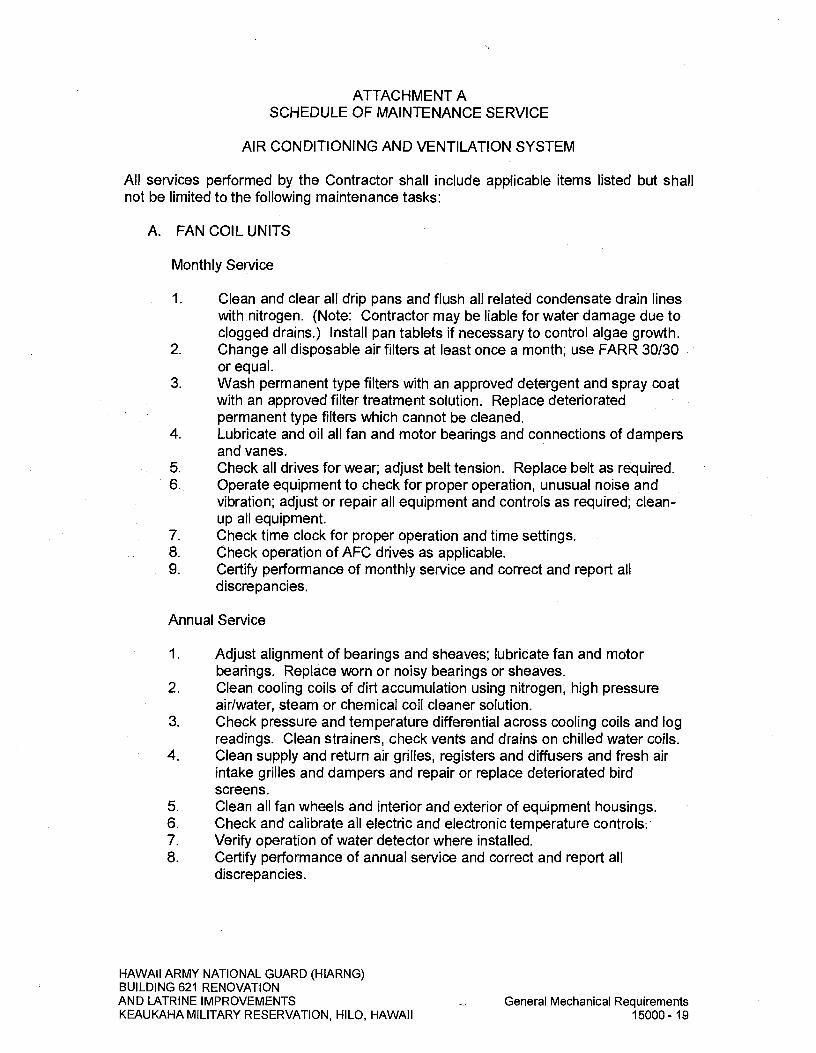
ATTACHMENT A SCHEDULE OF MAINTENANCE SERVICE
AIR CONDITIONING AND VENTILATION SYSTEM
All services performed by the Contractor shall include applicable items listed but shall not be limited to the following maintenance tasks:
A. FAN COIL UNITS
Monthly Service
I Clean and clear all drip pans and flush all related condensate drain lines with nitrogen. (Note: Contractor may be liable for water damage due to clogged drains.) Install pan tablets if necessary to control algae growth.
2. Change all disposable air filters at least once a month; use FARR 30/30 or equal.
3. Wash permanent type filters with an approved detergent and spray coat with an approved filter treatment solution. Replace deteriorated permanent type filters which cannot be cleaned.
4. Lubricate and oil all fan and motor bearings and connections of dampers and vanes.
5. Check all drives for wear; adjust belt tension. Replace belt as required. 6. Operate equipment to check for proper operation, unusual noise and
vibration; adjust or repair all equipment and controls as required; clean-up all equipment.
7. Check time clock for proper operation and time settings. 8. Check operation of AFC drives as applicable. 9. Certify performance of monthly service and correct and report all
discrepancies.
Annual Service
1. Adjust alignment of bearings and sheaves; lubricate fan and motor bearings. Replace worn or noisy bearings or sheaves.
2. Clean cooling coils of dirt accumulation using nitrogen, high pressure air/water, steam or chemical coil cleaner solution.
3. Check pressure and temperature differential across cooling coils and log readings. Clean strainers, check vents and drains on chilled water coils.
4. Clean supply and return air grilles, registers and diffusers and fresh air intake grilles and dampers and repair or replace deteriorated bird screens.
5. Clean all fan wheels and interior and exterior of equipment housings. 6. Check and calibrate all electric and electronic temperature controls-.7.
ontrols:7. Verify operation of water detector where installed.
8. Certify performance of annual service and correct and report all discrepancies.
HAWAII ARMY NATIONAL GUARD (HIARNG) BUILDING 621 RENOVATION AND LATRINE IMPROVEMENTS
General Mechanical Requirements
KEAUKAHA MILITARY RESERVATION, HILO, HAWAII
15000-19

B. AIR COOLED CONDENSING UNITS
Monthly Service
1. Read and record refrigerant oil gauge pressures. 2. Read and record compressor motor voltage. 3. Read and record compressor motor current. 4. Check compressor bearing oil pressure, oil level. Add oil as required. 5. Check refrigerant charge. Add refrigerant as required. 6. Check and record findings or refrigerant moisture indicator. 7. Check and record findings of compressor capacity control. 8. Check and report findings for refrigerant, or oil leak and repair as
required. 9. Check and record findings of operation of all operating and safety
controls. 10. Check for undue noise and vibration and repair as required.
Quarterly Service
1. Check setting of all operating and control electrical contacts and repair as required.
2. Clean all starter contacts and control electrical contacts and repair as required.
Semi-annual Service
1. Check compressor crankcase oil condition. Perform acid test. 2. Check for rust spots, clean and touch-up with paint.
Annual Service
1. Change complete compressor oil and filters.
C. EXHAUST FANS
Quarterly Service
1. Check motor-controlled and back-draft dampers for proper operation; lubricate linkage for free movement.
2. Lubricate fan motors and bearings. 3. Check belt wear and tension; adjust or replace as needed. 4. Check sheaves for wear, replace as needed. 5. Check fan collar, bearings and shaft for wear, repair or replace as
needed. 6. Supply air fan and intake penthouse only: Change all disposable air
filters; use Farr 30/30 or equal. Remove and wash intake louvers or grilles. Wash permanent type filters with an approved detergent and spray coat with an approved filter treatment solution. Replace deteriorated permanent type filters which cannot be cleaned.
7. Certify performance of quarterly maintenance service and correct and report all discrepancies.
HAWAII ARMY NATIONAL GUARD (HIARNG) BUILDING 621 RENOVATION AND LATRINE IMPROVEMENTS
General Mechanical Requirements
KEAUKAHA MILITARY RESERVATION, HILO, HAWAII
15000-20

Semi-Annual Service
1. Check and clean fan wheels and housings of dust, dirt and grease. 2. Remove and wash all intake grilles and dampers and repair or replace
deteriorated bird screens. 3. Certify performance of quarterly maintenance service and correct and
report all discrepancies.
D. AIR DISTRIBUTION SYSTEM
Monthly Service
1. Check ductwork for leakage, damage, and corrosion. 2. Check duct and devices for noise and vibration. 3. Check ductwork for loose connections and damage. 4. Certify performance of monthly maintenance service and correct and
report all discrepancies.
Semi-Annual Service
1. Clean all air devices. 2. Re-balance and test complete system including adjustment of fan speeds
and measurement of cooling coil performance to restore to the operating conditions from the test and balance report submitted during construction. Submit test and balance report after completion.
3. Paint damaged or weathered ductwork. 4. Certify performance of monthly maintenance service and correct and
report all discrepancies.
E. CONDENSATE DRAIN PIPING
Monthly Service
1. Clean and clear all drip pans and flush all related condensate drain lines with nitrogen. (Note: Contractor may be liable for water damage due to clogged drains.) Install pan tablets if necessary to control algae growth
2. Check all condensate drain piping and fittings for leaks. 3. Check condition of insulation; re-insulate as necessary. 4. Drain dirt leg. 5. Certify performance of monthly maintenance service and that all
discrepancies are reported and corrected.
HAWAII ARMY NATIONAL GUARD (HIARNG) BUILDING 621 RENOVATION AND LATRINE IMPROVEMENTS
General Mechanical Requirements
KEAUKAHA MILITARY RESERVATION, HILO, HAWAII
15000-21

F. TEMPERATURE CONTROLS (FOR PACKAGED EQUIPMENT WITH INTERNAL CONTROLS)
Quarterly Service
1. Check control devices for proper operation, sticking stems and calibration; repair or replace weak or broken springs and all other parts.
2. Check automatic dampers for tightness in closing, bent blades and defective linkage; lubricate connections for free movement and repair as required.
3. Adjust thermostat to maintain 75 degrees F room temperature or operation set points as desired.
4. Certify performance of quarterly maintenance service and that all discrepancies are reported and corrected.
HAWAII ARMY NATIONAL GUARD (HIARNG) BUILDING 621 RENOVATION AND LATRINE IMPROVEMENTS
General Mechanical Requirements
KEAUKAHA MILITARY RESERVATION, HILO, HAWAII
15000-22

ATTACHMENT B SCHEDULE OF MAINTENANCE SERVICE
PLUMBING SYSTEM
All services performed by the Contractor shall include applicable items listed but shall not be limited to the following maintenance tasks:
A. GAS WATER HEATER AND HOT WATER STORAGE TANKS
Monthly Service
1. Check and record water temperatures and pressures of gas water heater and hot water storage tanks in "maintenance log book."
2. Visual check for gas and water leakage; correct or repair as required. 3. Check gas water heater circulation hot water pump for abnormal
temperature and unusual noise; lubricate and/or replace as required. 4. Adjust hot water temperature setting for seasonal change. 5. Note and run system operation through complete operating cycle and
adjust for proper operation. Certify performance of monthly maintenance service and correct and report all discrepancies.
Quarterly Service
1. Start up heater if in standby and check water temperature setpoints, circulating hot water pump is operational and water leaving heater meets the setpoint. Check controls are operational. Repair controls that are not properly operating.
2. For unsealed combustion chambers, observe combustion chamber and check for proper combustion and condition of the combustion chamber. Clean burners if dirty and remove debris and soot from combustion chamber.
3. Visual check for gas and water leakage; correct or repair as required. 4. Certify performance of quarterly maintenance service and correct and
report all discrepancies.
Annual Service
1. Test relief valves to ensure they are operational. Replace if leaking or do not reseat.
2. Perform quarterly services. 3. Certify performance of annual maintenance service and correct and
report all discrepancies.
B. HOT WATER RETURN PUMPS
Quarterly Service
1. Lubricate and check pump and motor bearings for abnormal temperature and unusual noise or vibration and repair as needed.
HAWAII ARMY NATIONAL GUARD (HIARNG) BUILDING 621 RENOVATION AND LATRINE IMPROVEMENTS
General Mechanical Requirements
KEAUKAHA MILITARY RESERVATION, HILO, HAWAII
15000-23

2. Check packing glands and seals for excessive leakage. Adjust, tighten or replace as required.
3. Certify performance of quarterly maintenance service and correct and report all discrepancies.
Semi-Annual Service
1. Check and blow down strainer to all pumps. Remove, clean and reinstall strainer if excessive debris is noted.
2. Check condition of insulation; re-insulate as necessary. 3. Log suction and discharge pressures. 4. Clean and remove all dust and foreign matter. Clean all rust spots and
scratches and tough-up paint with matching color. 5. Lubricate pump motor bearings as required. 6. Check motor coupling for alignment; check and make sure mounting
bolts are secure. 7. Certify performance of semi-annual maintenance service and correct and
report all discrepancies.
C. VALVES, EQUIPMENT AND SUPPORTS
1. The Contractor shall exercise all equipment shut-off valves annually for proper operation and tightness.
2. Wirebrush, prime and paint rust from pipe, equipment and support surface to prevent further rusting.
3. Certify that all discrepancies are reported and corrected.
D. CLEANING OF MECHANICAL EQUIPMENT ROOMS OR ENCLOSURES
Monthly
1. Vacuum or wipe clean all equipment surfaces and all related appurtenance.
2. Vacuum clean or sweep complete floor and platform areas. DO NOT wet floor and platform area where there is no waterproofing.
3. Wet wash complete floor area with tap water where allowed. Remove all used, deteriorated, replaced, discarded parts and related debris. CAUTION: DO NOT splash water onto electrical and mechanical equipment.
4. Notify Manager-in-Charge of any dangerous conditions, improper storage of furniture, materials and supplies which impacts your work within rooms and enclosures, including vandalism.
END OF SECTION
HAWAII ARMY NATIONAL GUARD (HIARNG) BUILDING 621 RENOVATION AND LATRINE IMPROVEMENTS
General Mechanical Requirements
KEAUKAHA MILITARY RESERVATION, HILO, HAWAII
15000-24

SECTION 15070 - MECHANICAL SOUND, VIBRATION, AND SEISMIC CONTROL
PART I - GENERAL
1.01 SUMMARY A. This section covers the furnishing, fabrication, delivery and installation of the
sound, vibration and seismic control equipment for the air conditioning, ventilation and plumbing systems complete, including but not limited to the following: 1. Vibration isolators.
2. Flexible connections for piping.
3. Flexible duct connections.
4. Seismic control equipment.
5 Manufacturer's literature, shop drawings and record drawings.
102 RELATED WORK SPECIFIED IN OTHER SECTIONS A. Mechanical work as specified in SECTION 15000 - GENERAL MECHANICAL
REQUIREMENTS unless specified otherwise in other sections of DIVISION 15- MECHANICAL.
B. Plumbing systems specified in SECTION 15400 - PLUMBING.
C. Unitary air conditioning equipment specified in SECTION 15730 - UNITARY AIR CONDITIONING EQUIPMENT.
D. Ductwork specified in SECTION 15810- DUCTWORK AND DUCTWORK ACCESSORIES.
1.03 REFERENCES A. The publications listed below form a part of this specification to the extent
referenced. The publications are referred to in the text by the basic designation only. 1. AMERICAN INSTITUTE OF STEEL CONSTRUCTION (AISC)
AISC S342L (1993) Load and Resistance Factor Design Specification for Structural Steel Buildings
2. AIR-CONDITIONING HEATING AND REFRIGERATION INSTITUTE (AHRI) AHRI 575 (2008) Method of Measuring Machinery Sound
Within an Equipment Space
3. AMERICAN SOCIETY FOR TESTING AND MATERIALS (ASTM) ASTM A 36/A 36M (2008) Standard Specifications for Carbon
Structural Steel
HAWAII ARMY NATIONAL GUARD (HIARNG) BUILDING 621 RENOVATION AND LATRINE IMPROVEMENTS Mechanical Sound, Vibration, and Seismic Control KEAUKAHA MILITARY RESERVATION, HILO, HAWAII 15070-1

ASTM A 123A/A123 M
ASTM A 653/A 653M
ASTM D 471
(2012) Standard Specifications for Zinc (Hot-Dip Galvanized) Coatings on Iron and Steel Products
(2011) Stand Specification for Steel Sheet Zinc-Coated (Galvanized) or Zinc-Iron Alloy-Coated (Galvannealed) by the Hot-Dip Process
(2012a) Rubber Property - Effect of Liquids
ASTM D 2240 (2005; R 2010) Rubber Property - Durometer Hardness
ASTM E 84 (2012c) Surface Burning Characteristics of Building Materials
4. AMERICAN WELDING SOCIETY, INC. (AWS) AWS D1.1 (2012) Structural Welding Code Steel
5. SHEET METAL & AIR CONDITIONING CONTRACTORS' NATIONAL ASSOCIATION, INC. (SMACNA) SMACNA 1403 (2008) Accepted Industry Practice for Industrial
Duct Construction
SMACNA 1981 (2008) Seismic Restraint Manual Guidelines for Mechanical Systems
6. NUSIG INC. (1997) National Uniform Seismic Installation Guidelines
1.04 A.
B.
DEFINITIONS Decibels dB: Measure of sound level. Decibels are referenced to either, 20 uPa for sound pressure levels or one pW for sound power levels. dBA is the overall "A" weighted sound level.
Machinery: The vibration or noise producing equipment that must be isolated.
C. Manufacturer: The fabricator or supplier of vibration-isolation or seismic-protection materials and equipment. For mechanical equipment and machinery the term machinery manufacturer will be used.
D. Micropascal uPa: 10 to the minus 6 power newtons per square meter.
E. Picowatt pW: 10 to the minus 12 power wafts.
1.05 A.
SYSTEM DESCRIPTION Machinery Vibration Criteria: Provide vibration isolators for mechanical and electrical machinery and associated piping and ductwork as indicated, to minimize transmission of vibrations and structure borne noise to the building structure or spaces or from the building structure to the machinery. Provide vibration isolator type and static deflection in accordance with the following:
HAWAII ARMY NATIONAL GUARD (HIARNG) BUILDING 621 RENOVATION AND LATRINE IMPROVEMENTS Mechanical Sound, Vibration, and Seismic Control KEAUKAHA MILITARY RESERVATION, HILO, HAWAII 15070-2
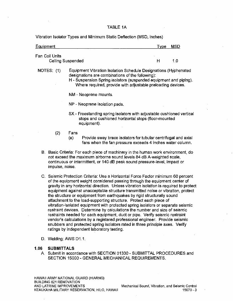
TABLE IA
Vibration Isolator Types and Minimum Static Deflection (MSD, inches)
Equipment Type MSD
Fan Coil Units Ceiling Suspended H 1.0
NOTES: (1) Equipment Vibration Isolation Schedule Designations (Hyphenated designations are combinations of the following): H - Suspension Spring isolators (suspended equipment and piping).
Where required, provide with adjustable preloading devices.
NM - Neoprene mounts.
NP - Neoprene isolation pads.
SX - Freestanding spring isolators with adjustable cushioned vertical stops and cushioned horizontal stops (floor-mounted equipment).
(2) Fans (a) Provide sway brace isolators for tubular centrifugal and axial
fans when the fan pressure exceeds 4 inches water column.
B. Basic Criteria: For each piece of machinery in the human work environment, do not exceed the maximum airborne sound-,.levels 84 dB A-weighted scale, continuous or intermittent, or 140 dB peak-sound pressure-level, impact or impulse, noise.
C. Seismic Protection Criteria: Use a Horizontal Force Factor minimum 60 percent of the equipment weight considered passing through the equipment center of gravity in any horizontal direction. Unless vibration isolation is required to protect equipment against unacceptable structure transmitted noise or vibration, protect the structure or equipment from earthquakes by rigid structurally sound attachment to the load-supporting structure. Protect each piece of vibration-isolated equipment with protected spring isolators or separate seismic restraint devices. Determine by calculations the number and size of seismic restraints needed for each equipment, duct or pipe. Verify seismic restraint vendor's calculations by a registered professional engineer. Provide seismic snubbers and protected spring isolators rated in three principle axes. Verify ratings by independent laboratory testing.
D. Welding: AWS D1.1.
1.06 SUBMITTALS A. Submit in accordance with SECTION 01330 - SUBMITTAL PROCEDURES and
SECTION 15000 - GENERAL MECHANICAL REQUIREMENTS.
HAWAII ARMY NATIONAL GUARD (HIARNG) BUILDING 621 RENOVATION AND LATRINE IMPROVEMENTS Mechanical Sound, Vibration, and Seismic Control KEAUKAHA MILITARY RESERVATION, HILO, HAWAII 15070-3
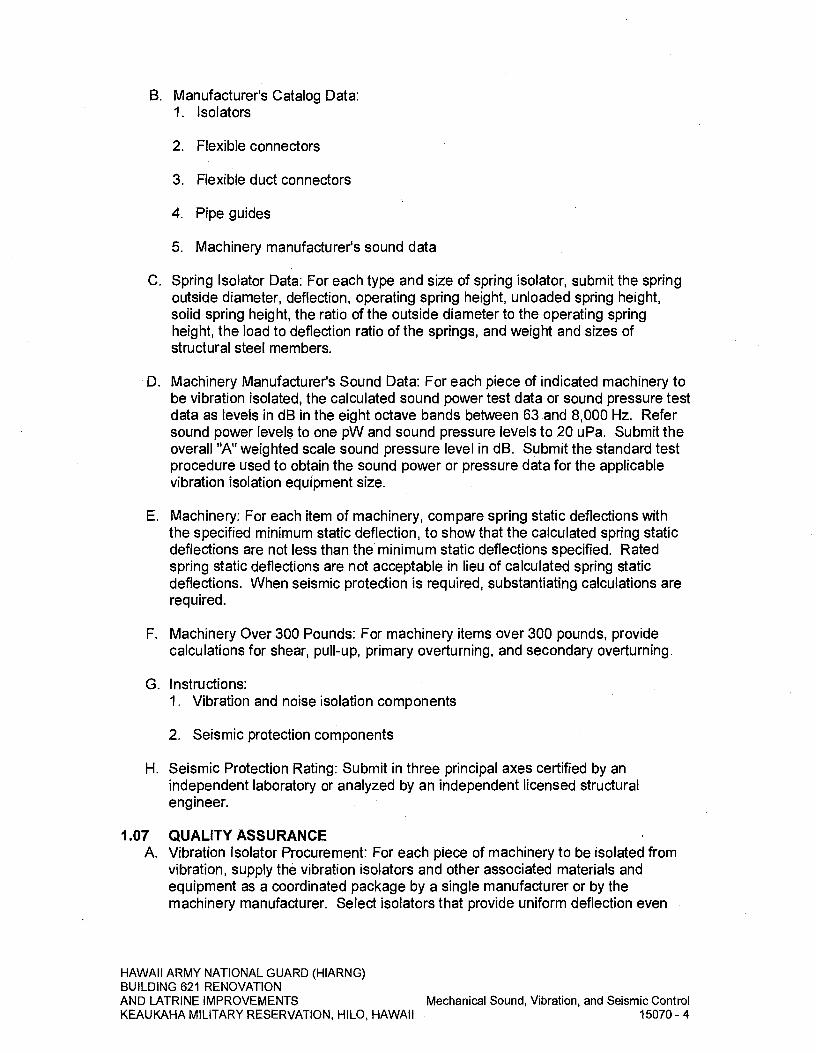
B. Manufacturer's Catalog Data: 1. Isolators
2. Flexible connectors
3. Flexible duct connectors
4. Pipe guides
5. Machinery manufacturer's sound data
C. Spring Isolator Data: For each type and size of spring isolator, submit the spring outside diameter, deflection, operating spring height, unloaded spring height, solid spring height, the ratio of the outside diameter to the operating spring height, the load to deflection ratio of the springs, and weight and sizes of structural steel members.
D. Machinery Manufacturer's Sound Data: For each piece of indicated machinery to be vibration isolated, the calculated sound power test data or sound pressure test data as levels in dB in the eight octave bands between 63 and 8,000 Hz. Refer sound power levels to one pW and sound pressure levels to 20 uPa. Submit the overall "A" weighted scale sound pressure level in dB. Submit the standard test procedure used to obtain the sound power or pressure data for the applicable vibration isolation equipment size.
E. Machinery: For each item of machinery, compare spring static deflections with the specified minimum static deflection, to show that -the calculated spring static deflections are not less than the minimum static deflections specified. Rated spring static deflections are not acceptable in lieu of calculated spring static deflections. When seismic protection is required, substantiating calculations are required.
F. Machinery Over 300 Pounds: For machinery items over 300 pounds, provide calculations for shear, pull-up, primary overturning, and secondary overturning.
G. Instructions: 1. Vibration and noise isolation components
2. Seismic protection components
H. Seismic Protection Rating: Submit in three principal axes certified by an independent laboratory or analyzed by an independent licensed structural engineer.
1.07 QUALITY ASSURANCE A. Vibration Isolator Procurement: For each piece of machinery to be isolated from
vibration, supply the vibration isolators and other associated materials and equipment as a coordinated package by a single manufacturer or by the machinery manufacturer. Select isolators that provide uniform deflection even
HAWAII ARMY NATIONAL GUARD (HIARNG) BUILDING 621 RENOVATION AND LATRINE IMPROVEMENTS Mechanical Sound, Vibration, and Seismic Control KEAUKAHA MILITARY RESERVATION, HILO, HAWAII 15070-4

when machinery weight is not evenly distributed. This requirement does not include the flexible connectors or the hangers for the associated piping and ductwork.
B. Unitized Machinery Assemblies: Mounting of unitized assemblies directly on vibration isolation springs is acceptable if machinery manufacturer certifies that the end supports of the assemblies have been designed for such installation.
PART 2 - PRODUCTS
2.01 CORROSION PROTECTION FOR STEEL PARTS A. ASTM A 123, ASTM A 653 hot-dipped galvanized, or equivalent manufacturer
standard coatings. Where steel parts are exposed to the weather, provide galvanized coating of at least 2-ounces of zinc per square foot of surface. Coat springs with neoprene.
2.02 NEOPRENE A. ASTM D 471 and ASTM D 2240, Grade Durometer 40, 50, or 60, and oil
resistant.
2.03 FLOOR-MOUNTED ISOLATORS A. Neoprene Isolation Pads: Provide pads at least 1/4-inch thick with cross-ribbed
or waffle design. For concentrated loads, provide steel bearing plates bonded or cold cemented to the pads. Mountings shall be as manufactured by Mason Industries, Inc., M.W. Sausse, Amberbooth, Caldyn or approved equal.
2.04 SUSPENSION ISOLATORS A. Provide hangers with suspension isolators encased in open steel brackets.
Isolate hanger rods from isolator steel brackets with neoprene-lined opening. 1. Suspension Spring Isolators: Provide hangers with springs and molded
double deflection neoprene elements in series. Provide isolators with adjustable spring-preloading devices where required to maintain constant pipe elevations during installation and when pipe operational loads are transferred to the springs. Neoprene elements shall have a minimum deflection of 0.35 inches. Provide springs with outside coil diameters at least 0.8 of the operating height. At operating height, springs shall have additional travel to complete (solid) compression equal to at least 50 percent of the operating deflection. Spring isolators shall be as manufactured by Mason Industries, Inc., M.W. Sausse, Amberbooth, Caldyn or approved equal.
2.05 FLEXIBLE CONNECTORS FOR PIPING A. Straight or elbow flexible connectors rated for temperatures, pressures, and
fluids to be conveyed. Provide flexible connectors with the strength 4 times operating pressure at highest system operating temperature. Provide elbow flexible connectors with a permanently set angle. 1.
Elastomeric Flexible Connectors: Flexible neoprene connectors with Hypa Ion cover shall be provided in all water piping connections to pumps and air handling units where pipe is greater than 2 inch nominal diameter. Connectors shall be of neoprene, single sphere, with ductile iron Class 150 flanged connections. Flanged assemblies shall be equipped with limit bolt to
HAWAII ARMY NATIONAL GUARD (HIARNG) BUILDING 621 RENOVATION AND LATRINE IMPROVEMENTS Mechanical Sound, Vibration, and Seismic Control KEAUKAHA MILITARY RESERVATION, HILO, HAWAII 15070-5

restrict maximum travel and resist pressure thrusts. Connectors shall have a minimum rating of 225 psi at 170 degrees F operating temperature. All materials shall be suitable for use in chilled water systems and outdoor environments. Connectors shall be Mason Industries, Inc., Type MFNC, Mercer Rubber or approved equal.
2. Flexible Hoses: Metallic braided bronze hoses shall be provided in all chilled water piping to the pumps, air handling units and fan coil units where pipe is 2 inch or less nominal diameter. Hoses shall be Mercer BBF, Mason Industries, Inc. or equal. Provide soldered or threaded ends. Lengths shall be 6 times the nominal diameter with a maximum of 36 inches. Hoses shall be installed on equipment side of shut-off valves and horizontally wherever possible.
2.07 FLEXIBLE DUCT CONNECTORS A. Provide flexible duct connectors fabricated in accordance with SMACNA DCS.
2.08 SEISMIC PROTECTION COMPONENTS FOR PIPING AND DUCTWORK A. Provide in accordance with SMACNA SRM and the National Uniform Seismic
Installation Guidelines (NUSIG).
PART 3- EXECUTION
3.01 INSTALLATION A. Vibration and Noise Isolation Components: Install vibration and noise isolation
materials and equipment as indicated and in accordance with machinery manufacturer's instructions.
B. Suspension Vibration Isolators: Provide suspension isolation hangers for suspended equipment as indicated and as specified.
C. Flexible Pipe and Duct Connectors: Install flexible connectors in accordance with the manufacturer's instructions. When liquid pulsation dampening is required, flexible connectors with spherical configuration may be used. Provide restraints for pipe connectors at pumps to prevent connector failure upon pump startup.
D. Machinery: Provide vibration isolators, flexible connectors in accordance with manufacturer's recommendations. Machinery with spring isolators or protected spring isolators shall rock or move freely within limits of stops or seismic snubber restraints. 1. Stability: Isolators shall be stable during starting and stopping of machinery
without traverse and eccentric movement of machinery that would damage or adversely affect the machinery or attachments.
2. Lateral Motion: The installed vibration isolation system for each piece of floor or ceiling mounted machinery shall have a maximum lateral motion under machinery start up and shut down conditions of not more than 1/4-inch. Restrain motions in excess by approved spring mountings.
HAWAII ARMY NATIONAL GUARD (HIARNG) BUILDING 621 RENOVATION AND LATRINE IMPROVEMENTS Mechanical Sound, Vibration, and Seismic Control KEAUKAHA MILITARY RESERVATION, HILO, HAWAII 15070-6

3. Unbalanced Machinery: Provide foundation suspension systems specifically designed to resist horizontal forces for machinery with large unbalanced horizontal forces. Vibration isolator systems shall conform to the machinery manufacturer's recommendations.
E. Piping and High Pressure Ductwork: Provide vibration isolation for piping and high pressure ductwork with over 6 inches water column. The isolator deflections shall be equal to or greater than the static deflection of the vibration isolators provided for the connected machinery as follows: 1. High Pressure Ductwork: For a distance of 50 feet from fans, exhausters and
blowers.
2. Piping Connected to Vibration Isolated Machinery: For a distance of 50 feet or 50 pipe diameters, whichever is greater.
3. Chilled Water Piping: For risers from pumps and for the first 20 feet of the branch connection of the main supply and return piping at each floor.
F. Pipe Hanger and Support Installation: 1. Pipe Hangers: Provide eye-bolts or swivel joints for pipe hangers to permit
pipe thermal or mechanical movement without angular misalignment of hanger vibration isolator.
2. Pipe Risers: Provide pipe riser supports with bearing plates and two layers of 1/4-inch thick ribbed or waffled neoprene pad loaded to not more than 50 psi. Separate isolation pads with 1/4-inch steel plate. Weld pipe riser clamps at anchor points to the pipe and to pairs of vertical acoustical pipe anchor mountings which shall be rigidly fastened to the steel framing.
3. Supports at Base of Pipe Risers: Piping isolation supports at the base of risers shall be two layers of 1/2-inch thick heavy-duty neoprene pad separated by 1/4-inch thick steel plate. Use bearing plates sized to provide a pad loading of not more than 500 psi. Weld the stanchion between the pipe and isolation support to the pipe and weld or bolt to the isolation support. Bolt isolation support to the floor slab with resilient sleeves and washers. Where supplementary steel is required to support piping, provide a maximum deflection of 0.08 inches at the mid-span of this steel under the load. Rigidly support piping from the supplementary steel with the supplementary steel isolated from the building structure with isolators.
.G. High Pressure Ductwork Hanger and Support Installation: Provide ductwork with vibration isolation hangers and supports where required or indicated. Connect ductwork to equipment with flexible duct connectors. Segment ductwork with flexible duct connectors. 1. Duct Risers: Provide duct riser supports within shafts with suitable bearing
plates and two layers of 1/4-inch thick ribbed or waffled neoprene pad loaded to not more than 50 psi. Separate isolation pads with 1/4-inch steel plate.
HAWAII ARMY NATIONAL GUARD (HIARNG) BUILDING 621 RENOVATION AND LATRINE IMPROVEMENTS
Mechanical Sound, Vibration, and Seismic Control
KEAUKAHA MILITARY RESERVATION, HILO, HAWAII
15070-7
2. Supports at Base of Duct Risers: For duct isolation supports at the base of risers, provide two layers of 1/2-inch thick heavy-duty neoprene pad separated by 1/47inch thick steel plate. Use bearing plates sized to provide a pad loading of not more than 500 psi. Weld the stanchion between the duct and isolation support to the pipe, and weld or bolt to the isolation support. Bolt isolation support to the floor slab with resilient sleeves and washers. Where supplementary steel is required to support ducts, provide a maximum deflection of 1/4-inch at the midspan of this steel under the supported load. Rigidly support duct from the supplementary steel and the supplementary steel isolators.
H. Equipment Room Sound Isolation: Do not allow direct contact between pipe or ducts and walls, floor slabs, roofs, ceilings or partitions of equipment rooms. 1. Pipe Penetrations: Provide galvanized Schedule 40 pipe sleeves and tightly
pack annular space between sleeves and pipe with insulation having a flame spread rating not more than 25 and a smoke developed rating not more than 50 when tested in accordance with ASTM E 84, maximum effective temperature 1000 degrees F, bulk density 6 pounds/cubic-feet minimum. Provide uninsulated pipe with a 1 inch thick mineral fiber sleeve the full length of the penetration and seal each end with an interior non-hardening compound. Provide sealant and mineral-fiber sleeve of a flame spread rating not more than 25 and a smoke developed rating not more than 50 when tested in accordance with ASTM E 84.
2. Duct Penetrations: Pack openings around ducts with mineral fiber insulation the full length of the penetration having a flame spread rating not more than 25 and .a smoke developed rating not more than 50 when tested in accordance with ASTM E 84. At each end of duct opening provide sealing collars and seal with an interior non-hardening compound.
I. Seismic Restraints for Piping and Ductwork: Provide seismic restraints in accordance with SMACNA SRM and the National Uniform Seismic Installation Guidelines (NUSIG).
J. Systems Not To Be Vibration Isolated: Do not provide vibration isolation for electrical raceways and conduits or for fire protection (see SECTION 15300 - WET PIPE FIRE SPRINKLER SYSTEM), storm, sanitary, and domestic water piping systems which do not include pumps or other vibrating, rotating, or pulsating equipment including control and pressure reducing valves.
302 FIELD QUALITY CONTROL A. Notify State 14 days prior to machinery testing.
1. Field Inspections: Prior to initial operation, inspect the vibration isolators for conformance to drawings, specifications, and manufacturer's data and instructions. Check for vibration and noise transmission through connections, piping, ductwork, foundations, and walls. Check connector alignment before and after filling of system and during operation. Correct misalignment without damage to connector and in accordance with manufacturer's recommendations.
HAWAII ARMY NATIONAL GUARD (HIARNG) BUILDING 621 RENOVATION AND LATRINE IMPROVEMENTS Mechanical Sound, Vibration, and Seismic Control KEAUKAHA MILITARY RESERVATION, H1LO, HAWAII 15070-8
2. Spring Isolator Inspection: After installation of spring isolators or protected spring isolators, and seismic restraint devices, the machinery shall rock freely on its spring isolators within limits of stops or seismic restraint devices. Eliminate or correct interferences.
END OF SECTION
(
HAWAII ARMY NATIONAL GUARD (HIARNG) BUILDING 621 RENOVATION AND LATRINE IMPROVEMENTS Mechanical Sound, Vibration, and Seismic Control KEAUKAHA MILITARY RESERVATION, HILO, HAWAII 15070-9

SECTION 15080 - MECHANICAL INSULATION
PART I - GENERAL
1.01 SUMMARY A. This section covers the furnishing, fabrication, delivery and installation of the
insulation for air conditioning, ventilation, plumbing and generator auxiliary systems complete, including but not limited to the following: 1. Sheetmetal duct insulation.
2. Pipe Insulation.
3. Equipment Insulation
4. Manufacturer's literature, shop drawings and record drawings.
5. Inspection, test and guarantee.
1.02 RELATED WORK SPECIFIED IN OTHER SECTIONS A Mechanical work as specified in SECTION 15000- GENERAL MECHANICAL
REQUIREMENTS unless specified otherwise in other sections of DIVISION 15- MECHANICAL.
B. Plumbing systems specified in SECTION 15400 - PLUMBING.
C.. Unitary air conditioning equipment specified in SECTION 15730 - UNITARY AIR CONDITIONING EQUIPMENT.
• D: Ductwork specified in SECTION 15810- DUCTWORK AND DUCTWORK ACCESSORIES.
1.03 SUBMITTALS A. Submit in accordance with SECTION 01330- SUBMITTAL PROCEDURES and
SECTION 15000 - GENERAL MECHANICAL REQUIREMENTS.
B. Certificates of Conformance or Compliance: 1. Submit certificates of conformance for performance and characteristics
specified, the listed standards and in accordance with SECTION 15000 - GENERAL MECHANICAL REQUIREMENTS for the following: a. Pipe Insulation.
C. Product Data: Submit product data for the following: 1. Pipe insulation.
2. Equipment insulation that is not factory installed.
3. Insulation accessories including vapor barrier, tape, and other items.
HAWAII ARMY NATIONAL GUARD (HIARNG) BUILDING 621 RENOVATION AND LATRINE IMPROVEMENTS
Mechanical Insulation
KEAUKAHA MILITARY RESERVATION, HILO, HAWAII
15080-1
D. Listing: List of materials showing name and addresses of manufacturers; manufacturer's local supplier's name, address and phone number; catalog numbers and trade names.
E. Guarantee and Certificate: Submit one-year guarantee and certificate in accordance with SECTION 15000 - GENERAL MECHANICAL REQUIREMENTS.
PART 2- PRODUCTS
2.01 MATERIALS AND EQUIPMENT A. General:
1. Provide materials complying with NFPA Bulletin 90-A, as determined by UL method NFPA 225, ASTM E 84 or UL 181, with flame spread rating 25 and under and smoke developed rating 50 and under.
2. Where vapor barriers are used, provide intact and continuous throughout.
2.02 A.
PIPE INSULATION All above grade domestic hot water and hot water return, tempered water and tempered water return piping shall be insulated with Schuller Micro-Lok 650 with Vapor Barrier Jacket, Fiberglas heavy density pipe insulation with self-sealing, All Service Jacket (ASJ); Schuller; Certainteed or approved equal, having minimum density of 3.5 lb. cu. ft. and a maximum "K" factor of 0.22 Btu-in/hr-SF-degrees-F at 50 degrees F mean. Thickness of insulation shall be as follows:
Thickness
Pipe Size
Up to 2 inches 2-1/2-inches and over
1 inch 1-1/2-inches
B. The insulation shall be applied over clean, dry pipe with all joints firmly butted together. Longitudinal laps shall be sealed with Schuller vapor barrier adhesive, Foster or approved equal. Butt joints shall be wrapped with a 4 inch strip of the vapor barrier jacket cemented with vapor barrier adhesive. Each 3 foot section of insulation and each butt strip shall be additionally secured with 3/4-inch wide Schuller No. 357 white tape, Foster or approved equal.
C. Valve fitting for pipe sizes smaller than 4 inch shall be insulated with Schuller No.' 301 Insulating Cement, Foster or approved equal applied in one coat to a thickness equal to the adjoining tape insulation. Fittings for pipe sizes 4 inch and larger shall be insulated with Micro-Lok insulation, Owens-Corning, Certainteed or approved equal securely wired in place, and finished with a leveling coat of Schuller No. 301 Insulating Cement, Foster or approved equal. All-fittings regardless of pipe size shall be finished with PVC fitting covers and sealed to maintain vapor barrier.
D. Clamps or hangers in contact with pipe shall be insulated separately in the same manner as fitting. The insulation shall be applied upward along the vertical hanger rod to a point not less than 6 inches and sealed off.
HAWAII ARMY NATIONAL GUARD (HIARNG) BUILDING 621 RENOVATION AND LATRINE IMPROVEMENTS
Mechanical Insulation
KEAUKAHA MILITARY RESERVATION, H1LO, HAWAII
15080-2

E. Protect pipe insulation at all hanger and support points. Where 1 inch thick insulation is used, it shall be protected by 12 inches long galvanized metal shield. Where 1-1/2-inch insulation is used, 12 inches long section of calcium silicate preformed pipe insulation with a vapor barrier jacket or cellular glass with vapor barrier jacket shall be installed at the hanger point and protected with a 16 gauge galvanized metal shield on the outside of the jacket.
F. Condensate drain piping and plumbing drain pipes receiving condensate from the air conditioning system shall be insulated with 3/4-inch thick flexible cellular insulation.
G. Refrigerant suction piping shall be insulated with 3/4-inch thick flexible cellular insulation. Provide aluminum jacket for exterior installation.
H. Aboveground outdoor pipe insulation for solar water or domestic hot water shall be finished with mastic and reinforcing fabric as recommended by the insulation manufacturer, covered with aluminum jacket, 0.106 inch thick and banded with stainless steel bands.
I. Cellular glass insulation shall comply to the requirements of ASTM C 552. Pittsburgh Corning Foamglas, Cell-U-Foam Corporation or approved equal.
2.04 OTHER MECHANICAL EQUIPMENT REQUIRING INSULATION A. Pipe hangers and supports for insulated pipes that contact the pipe surface
directly shall be insulated with same insulation system as the pipe insulation.
B. Strainers that are connected to insulated pipes. Insulate strainers with 1-1/2-inch thick cellular glass insulation. Finish insulation with ASJ vapor barrier.
C. Flow devices installed in insulated pipes. Insulate with same insulation system as adjacent pipe insulation. Provide removable insulation covers for test connections (e.g. connections to install portable flow meter) of the same material as the pipe insulation.
D. Parts of air handling equipment that are not factory insulated such as mixing boxes, return air plenums, etc. Insulate with same duct insulation system as connecting ductwork.
E. Equipment, pipes and related appurtenances that are indicated or specified to be insulated but were not factory insulated such as duct mounted reheat coils.
PART 3- EXECUTION
3.01 COOPERATION WITH OTHER TRADES AND CONFLICT IN WORK A. Contractor shall examine all drawings of proposed work and coordinate his work
with other trades. Work conflicts shall be brought to attention of State and work rearranged or modified in accordance with his decision.
HAWAII ARMY NATIONAL GUARD (HIARNG) BUILDING 621 RENOVATION AND LATRINE IMPROVEMENTS
Mechanical Insulation
KEAUKAHA MILITARY RESERVATION, HILO, HAWAII
15080-3

B. If changes in indicated locations or arrangements of work are required, they shall be made by Contractor without additional charge to the State provided that these changes were ordered before work is installed and no extra material or labor are required.
C. Should Contractor determine that extra material and labor will be required to accommodate any rearrangement, he shall first submit detailed estimate of cost for required changes and proceed with work only upon written authority of the Project Manager.
3.02 EQUIPMENT INSTALLATION A. Equipment shall be installed as indicated and in accordance with manufacturer's
recommendations and instructions.
B. All necessary supports shall be provided for equipment, appurtenances and duct as required. This work shall include any additional steel purlins, brackets, seismic restraints or supports.
3.03 WORKMANSHIP AND FABRICATION A. Pipe Insulation: Pipe Insulation (Except Cellular and Calcium Silicate Insulation):
Place sections of insulation around pipe and joints tightly butted into place. Draw jacket tight and smooth. Secure jacket with fire resistant adhesive, factory-applied self-sealing lap, or stainless steel outward clinching staples spaced not over 4 inches on center and 1/2-inch minimum from edge of lap. Cover circumferential joints with butt strips, not less than 3 inches wide, of material identical to jacket material. Overlap longitudinal laps of jacket material not less than 1-1/2-inches. Adhesive used to secure buff strip shall be same as that used to secure jacket laps. Apply staples to both edges of butt strips. 1. Vapor Barrier Jacket: When a vapor barrier jacket is required, as indicated in
Table 1, on ends of sections of insulation that butt against flanges, unions, valves, fittings, and joints, provide a vapor barrier coating or manufacturer's weatherproof coating for outside service unless pipe is supplied with factory-applied self-seal lap. Apply vapor barrier coating at longitudinal and circumferential laps. Patch damaged jacket material by wrapping a strip of jacket material around the pipe and cementing, stapling, and coating as specified for butt strips. Extend patch not less than 1-1/2 inches past the break in both directions. At penetrations by pressure gages and thermometers, fill voids with vapor barrier coating for outside service. Seal with a brush coat of the same coating.
2. Roof: Where pipe penetrates, insulate piping to a point flush with top of flashing and seal with vapor barrier coating. Buff top of flashing and interior insulation tightly to exterior insulation. Extend exterior metal jacket 2 inches to fold down beyond end of insulation. Seal flashing and counterflashing underneath with vapor barrier coating.
B. Flexible Cellular Insulation: Bond cuts, buff joints, ends, and longitudinal joints with adhesive. Miter 90-degree turns and elbows, tees, and valve insulation. Where pipes penetrate fire walls, provide mineral-fiber insulation inserts and sheet-metal sleeves. Insulate flanges, unions, valves, and fittings in accordance with manufacturer's published instructions. Apply two coats of finish as
HAWAII ARMY NATIONAL GUARD (HIARNG) BUILDING 621 RENOVATION AND LATRINE IMPROVEMENTS
Mechanical Insulation
KEAUKAHA MILITARY RESERVATION, HILO, HAWAII
15080-4
recommended by insulation manufacturers to flexible unicellular insulation in outside locations. Do not use vinyl lacquer finish or equivalent. Use metal jackets on cellular insulation located outside.
3.04 PAINTING AND IDENTIFYING OF PIPING A.
General: The following items furnished under this section are to be painted and identified under SECTION 09900 - PAINTING. Do not paint over name plates or other identifying labels. 1. Exposed pipe insulation.
2. Exposed duct insulation.
3. Exposed equipment insulation that is unfinished.
3.05 ADJUSTING AND CLEANING A. Pipes, equipment and ducts shall be cleaned free of scale and thoroughly
flushed of all foreign matter prior to field insulation. Equipment shall be wiped clean, with all traces of oil, dust, dirt, or paint spots removed. Pipe hangers and supports that were temporarily loosened to allow installation of the insulation, shall be repositioned and adjusted to carry the load without crushing the insulation.
END OF SECTION
HAWAII ARMY NATIONAL GUARD (H1ARNG) BUILDING 621 RENOVATION AND LATRINE IMPROVEMENTS
Mechanical Insulation
KEAUKAHA MILITARY RESERVATION, HILO, HAWAII
15080-5

SECTION 15300 - WET PIPE FIRE SPRINKLER SYSTEMS
PART I - GENERAL
1.01 SUMMARY A. This.section includes designing and modifying an existing automatic wet pipe fire
sprinkler system to afford 100 percent complete fire protection coverage throughout the indicated areas. The design, equipment, materials, installation, and workmanship shall be in strict accordance with the required and advisory provisions of NFPA 13, except as modified herein. The systems shall include all materials, accessories, and equipment necessary to provide the system complete and ready for use. Install the system to give full consideration to blind spaces, piping, electrical equipment, ductwork, structural members, architectural features, and all other construction and equipment to afford complete coverage in accordance with detailed drawings to be submitted for approval. All devices and equipment for fire protection service shall be listed by the Underwriters Laboratories Inc. (UL) or approved by FM Approvals (FM). In the National Fire Protection Association (NFPA) publications referred to herein, the advisory provisions shall be considered to be mandatory, as though the word "shall" had been substituted for "should" wherever it appears; reference to the "authority having jurisdiction" shall be interpreted to mean the Hawaii Army National Guard Construction & Facilities Management Officer. Reference to the "Building Department" on the Contract Drawings and herein shall be interpreted to mean the Hawaii County Department of Public Works. Reference to the Fire Department on the Contract Drawings and herein shall be interpreted to mean the Hawaii County Fire Department. Reference to the "State" on the Contract Drawings and herein shall be interpreted to mean the State of Hawaii Department of Defense. "Provide" shall mean "furnish and install" when used herein.
1.02 RELATED WORK SPECIFIED IN OTHER SECTIONS A. Painting work specified in DIVISION 9 - FINISHES.
B. Portable fire extinguishers specified in SECTION 10520 - FIRE EXTINGUISHERS AND CABINETS.
C. Fire alarm work specified in SECTION 13850 - FIRE ALARM SYSTEMS.
D. General mechanical requirements as specified in SECTION 15000- GENERAL MECHANICAL REQUIREMENTS unless specified otherwise in other sections of DIVISION 15- MECHANICAL.
1.03 QUALITY ASSURANCE A. Comply with all the requirements of the State of Hawaii, County of Hawaii, and
applicable utility companies.
B. Obtain and pay for all fees, permits, licenses, assessments, connection charges, and inspections required for the work specified in this section.
HAWAII ARMY NATIONAL GUARD (HIARNG) BUILDING 621 RENOVATION AND LATRINE IMPROVEMENTS
Wet Pipe Fire Sprinkler Systems
KEAUKAHA MILITARY RESERVATION, HILO, HAWAII
15300-I
C. Comply with the recommendations and requirements of the Codes and Standards listed in this section in addition to detailed requirements of this specification. In the event of conflicting requirements, this specification shall prevail. 1. ASTM International Publications:
A 53 Pipe, Steel, Black and Hot-Dipped, Zinc-Coated, Welded and Seamless
A 135 Electric-Resistance-Welded Steel Pipe A 795 Black and Hot-Dipped Zinc Coated (Galvanized) Welded and
Seamless Steel Pipe for Fire Protection Use
2. FM Global Publication: FM APP Approval Guide, Updated Online
3. National Fire Protection Association (NFPA) Publications: NFPA I Uniform Fire Code, 2012 Edition NFPA 13 Sprinkler Systems, 2013 Edition NFPA 24 Private Fire Service Mains and Their Appurtenances, 2010
Edition NFPA 70 National Electrical Code, 2011 Edition NFPA 72 National Fire Alarm and Signaling Code, 2013 Edition
6. Underwriters Laboratories Inc. Publications: ULFPED Fire Protection Equipment Directory, 2013 Edition UL FRD Fire Resistance Directory, 2013 Edition
1.04 QUALIFICATIONS OF INSTALLER A. Record of Prior Installations: Prior to installation, submit data for approval by the
Project Manager showing that the Contractor has successfully installed automatic fire sprinkler systems of the same type and design as specified herein, or that the Contractor has a firm contractual agreement with a subcontractor having such required experience. The data shall include the names and locations of at least five (5) separate installations for wet pipe fire sprinkler systems where the Contractor, or the subcontractor referred to above, has installed such systems. The Contractor shall indicate the type and design of each system and certify that each system has performed satisfactorily in the manner intended for a period of not less than 18 months.
B. Fire Protection Specialist: Perform work specified in this section under the supervision of and certified by the Fire Protection Specialist who is an individual registered professional engineer who has passed the fire protection engineering written examination administered by the National Council of Examiners for Engineering and Surveys (NCEES) or who is certified as a Level III Technician by National Institute for Certification in Engineering Technologies (NICET) in the Automatic Sprinkler System Layout subfield of Fire Protection Engineering Technology in accordance with NICET 1014-7. Submit the name and documentation of certification of the proposed Fire Protection Specialist no later than 14 days after the Notice to Proceed and prior to the submittal of the sprinkler system drawings and hydraulic calculations. The Fire Protection Specialist shall prepare and submit a list of the fire protection related submittals, no later than 7 days after the approval of the Fire Protection Specialist, from the
HAWAII ARMY NATIONAL GUARD (HIARNG) BUILDING 621 RENOVATION AND LATRINE IMPROVEMENTS
Wet Pipe Fire Sprinkler Systems
KEAUKAHA MILITARY RESERVATION, HILO, HAWAII
15300-2
Contract Submittal Register that relate to the successful installation of the sprinkler systems(s). The submittals identified on this list shall be accompanied by a letter of approval signed and dated by the Fire Protection Specialist when submitted to the Project Manager. The Fire Protection Specialist shall be regularly engaged in the design and installation of the type and complexity of system specified in the contract documents, and shall have served in a similar capacity for at least three systems that have performed in the manner intended for a period of not less than 6 months.
1.05 SUBMITTALS A. Submit in accordance with SECTION 01330 - SUBMITTAL PROCEDURES and
SECTION 15000 - GENERAL MECHANICAL REQUIREMENTS. Partial submittals will not be acceptable. The Project Manager will review and approve all submittals. Before work is commenced, submit for approval complete sets of working drawings for the fire sprinkler systems. Contractor shall check the submittals and certify that they are correct and in compliance with the Contract Drawings and Specifications. Submit eight (8) copies of the following for approval.
B. Shop Drawings (Working Plans): 1. Provide shop drawings showing the wet pipe fire sprinkler systems to be
installed by the Contractor. Prepare shop drawings on sheets 22 inches by 34 inches using a drawing scale not less than 1/8-inch equals 1 foot. Shop drawings shall be prepared in accordance with the requirements for "Working Plans," as specified in NFPA 13 and include all data essential to the proper installation of the system. Do not commence work until the design of the systems and the various components have been approved.
2. Prior to start of any construction, required copies of to-scale shop drawings of sprinkler piping, sprinkler heads, valves, etc. shall be submitted for review. No work shall be started without approval of the Project Manager. Shop drawings shall be fully dimensioned to show that the equipment and connections thereto fit within the space provided.
3. Review of shop drawings is confined to arrangement of equipment only and does not relieve the Contractor from responsibility for proper fit, performance, and construction. Any deviation from the Contract Drawings and/or specifications shall be clearly noted on the shop drawings. Since manufacturing methods vary, reasonable variations from the Contract Documents are acceptable; however, performance and material requirements are minimum and the Project Manager retains the right to judge the equality of any variation.
C. Manufacturer's Published Data: 1. As soon as practicable and within 20 days after award of contract and before
installation of any materials or equipment is begun, the Contractor shall submit a complete list of materials and equipment together with names and addresses of manufacturers, catalog numbers, and trade names to the Project Manager for approval. No consideration shall be given to partial lists submitted from time to time.
HAWAII ARMY NATIONAL GUARD (HIARNG) BUILDING 621 RENOVATION AND LATRINE IMPROVEMENTS
Wet Pipe Fire Sprinkler Systems
KEAUKAHA MILITARY RESERVATION, HILO, HAWAII
15300-3
2. Annotate descriptive data to show the specific model, type, and size of each item the Contractor proposes to furnish.
3. Approval of materials will be based on manufacturer's published rating. Any materials and equipment that are not in accordance with these specifications may be rejected.
D. Certificates of Compliance: 1. Contractor's material and test certificates per NFPA 13 for aboveground fire
sprinkler piping.
2. Contractor's material and test certificates per NFPA 13 for underground fire sprinkler piping.
3. Pipe and fittings.
4. Sprinkler piping chlorination certificate.
5. Fire Protection Specialist inspection report certifying the system was installed in accordance with the Contract Documents and applicable code requirements.
E. Calculations: Provide the following calculations, prepared in accordance with this specification and standards referenced herein, for review and approval. 1. Provide computer generated hydraulic calculations for the fire sprinkler
systems.
2. Sway bracing calculations prepared in accordance with NFPA 13 and this specification.
F. Record Drawings: Upon completion of work, submit accurate as-built drawings to the Project Manager. Show exact locations and sizes, as actually installed, of the fire sprinkler system on these record "as-built" drawings. Include a copy of the record drawings in each copy of the operation and maintenance manual described below. Provide six compact discs containing CAD files of record drawings.
G. Operating and Maintenance Instructions: Complete sets of bound instructions containing the manufacturer's operating and maintenance instructions for each piece of equipment shall be furnished to the Project Manager. Each set shall be permanently bound and shall have a hard cover. One complete set shall be furnished at the time the test procedure is submitted and the remaining sets shall be furnished before the contract is completed. The following identification shall be inscribed on the cover: the words "OPERATING AND MAINTENANCE INSTRUCTIONS," the name and location of the building, the name of the Contractor. Flysheets shall be placed before instructions covering each subject. The instructions shall be on sheets approximately 8-1/2-inches by 11 inches with large sheets of drawings folded in. The instructions shall include, but shall not be limited to, the following:
HAWAII ARMY NATIONAL GUARD (HIARNG) BUILDING 621 RENOVATION AND LATRINE IMPROVEMENTS
Wet Pipe Fire Sprinkler Systems
KEAUKAHA MILITARY RESERVATION, HILO, HAWAII
15300-4

1. Table of Contents
2. System layout showing sprinkler heads, piping, valves, and controls.
3. A control sequence describing start-up, operation, and shutdown.
4. Operating and maintenance instructions for each piece of equipment, including lubrication instructions.
5. Manufacturer's bulletins, catalog cuts, and descriptive data.
6. Equipment component lists and recommended spare parts.
7. All approved shop drawings, certificate of chlorination, certification that the work conforms to all applicable codes.
8. Operation and maintenance bulletins.
9. Manufacturer's warranty information.
H. Spare Parts List: Submit spare parts data for each different item of material and equipment specified. The data shall include a complete list of parts and supplies, with current unit prices and source of supply, and a list of parts recommended by the manufacturer to be replaced after 1 year and 3 years of service. Include a list of special tools and test equipment required for maintenance and testing of the products supplied.
I. Warranty: Submit warranty as noted under item entitled 'WARRANTY" hereinbelow.
1.06 WARRANTY A. General Warranty: Special warranty specified in this Article shall not deprive The
State of other rights The State may have under other provisions of the Contract Documents and shall be in addition to, and run concurrent with, other warranties made by Contractor under requirements of the Contract Documents.
B. Special Warranty - Guarantee 1. The Contractor shall guarantee the following items:
a. All equipment, accessories, and material furnished for a period of one (1) year from the date of final acceptance against all defects in material and workmanship. If any equipment, device, or material fails, does not operate satisfactorily, or shows undue wear, the Contractor will be notified, and shall be required to correct the defect and damage to other work caused by such defect immediately and at no additional cost to the State.
b. All equipment, devices, or material to provide the results specified or shown.
c. All piping to be drip free and properly installed to be free of vibration, pounding, or objectionable noise.
HAWAII ARMY NATIONAL GUARD (HIARNG) BUILDING 621 RENOVATION AND LATRINE IMPROVEMENTS
Wet Pipe Fire Sprinkler Systems
KEAUKAHA MILITARY RESERVATION, HILO, HAWAII
15300-5

2. The above guarantee shall not be interpreted as voiding, limiting, or reducing any equipment manufacturer's warranty or any guarantee permitted by law.
1.07 CONTRACT DRAWINGS A. Contract Drawings are essentially diagrammatic, indicating general layout and
approximate locations toward establishing the scope for uniform estimating basis for all bidders. They are not intended to be detailed construction working drawings. Equipment, ductwork, and piping shall fit into space allotted and shall allow adequate clearances for servicing and maintenance. Reasonable modifications to indicated locations and arrangement to suit job conditions shall not constitute basis for requesting additional funds from the State.
B. Verification of Dimensions: The Contractor shall be responsible for the coordination and proper relation of his or her work to the structure and to the work of all trades. The Contractor shall visit the premises and thoroughly familiarize himself or herself with all details of the work and notify the Project Manager of any discrepancies before performing any work.
PART 2- PRODUCTS
2.01 MATERIALS AND EQUIPMENT A. Materials and equipment shall be catalogued products of manufacturers regularly
engaged in production of such materials or equipment and shall be manufacturer's latest design that complies with the specification requirements. Materials and equipment shall duplicate items that have been in satisfactory commercial or industrial use at least 2 years prior to bid opening. Where two or more items of the same class of equipment are required, these items shall be products of a single manufacturer; however, the component parts of the items need not be the products of the same manufacturer except where specified. Each item of equipment shall have the manufacturer's nameplate. Name of the distributing agent in lieu of manufacturer's nameplate will not be acceptable.
B. All materials shall be new, of equivalent or better quality than of materials specified. For ease of maintenance and parts replacement, select equipment from a single manufacturer as much as possible. Substitutions require pre-bid approval.
C. All devices and equipment for fire protection service shall be UL listed or FM approved. 11
2.02 DESIGN OF SPRINKLER SYSTEM A. Hazard Classification shall be in accordance with NFPA 13 and as indicated on
Contract Drawings.
B. Location and spacing of sprinklers shall be in accordance with NFPA 13. Sprinklers shall be spaced uniformly on branch lines.
C. Distribution of water shall be essentially uniform throughout the hydraulically calculated most remote area.
HAWAII ARMY NATIONAL GUARD (HIARNG) BUILDING 621 RENOVATION AND LATRINE IMPROVEMENTS
Wet Pipe Fire Sprinkler Systems
KEAUKAHA MILITARY RESERVATION, HILO, HAWAII
15300-6
D. Size pipe to provide the specified density when the system is discharging the specified total maximum required flow.
E. Minimum design area shall be as indicated on the Contract Drawings. The sprinkler discharge design area shall be the hydraulically most remote area as defined in NFPA 13. Reductions in design area shall be approved by the Project Manager.
F. Hydraulic calculations shall include an outside hose allowance for hose streams as indicated on Contract Drawings.
G. Hydraulic calculations shall utilize the available water supply indicated on Contract Drawings.
H. Provide a design which is complete in all regards including, but not necessarily limited to: 1. Hydraulically designed, overhead wet pipe automatic sprinkler system
including piping and sprinkler heads in accordance with NFPA 13.
2. Disinfecting and testing of all fire sprinkler piping.
I. Arrangement: Conceal piping in areas with finished ceilings unless otherwise indicated on the Contract Drawings.
J. Friction losses in pipe shall be calculated in accordance with Hazen-Williams formula with "C" value of 120 for steel pipe for wet pipe sprinkler systems and 140 for cement lined ductile iron piping.
2.03 EQUIPMENT AND DEVICES A. Fire Sprinkler Heads:
1. Provide automatic closed head fire sprinklers. Fire sprinkler temperature rating, K-factor, response, and type shall be as indicated on Contract Drawings. Upright and pendent fire sprinklers shall be provided with manufacturer applied corrosion resistant finish (e.g. polyester or Teflon coating). Fire sprinklers shall not be equipped with 0-ring water seals. Fire sprinklers shall be UL listed or FM approved.
2. Provide a metal cabinet with spare sprinkler heads, three (3) sprinkler stoppers, and one (1) sprinkler head wrench for each type of sprinkler installed. Install cabinet adjacent to the fire alarm control panel. The quantity and types of spare sprinkler heads shall be provided as specified in NFPA 13.
B. Sprinkler Guards: Provide as indicated on Contract Drawings and where sprinklers are subject to potential mechanical damage. Sprinkler guards shall be UL listed or FM approved.
C. Hydraulic Design Data Nameplate: Provide permanently marked metal or rigid plastic hydraulic design data nameplate adjacent to spare sprinkler cabinet for fire sprinkler riser. Nameplate shall display data including, but not limited to, the location of the design area, discharge density, water flow and residual pressure
HAWAII ARMY NATIONAL GUARD (HIARNG) BUILDING 621 RENOVATION AND LATRINE IMPROVEMENTS
Wet Pipe Fire Sprinkler Systems
KEAUKAHA MILITARY RESERVATION, HILO, HAWAII
15300-7

demand at the point where the sprinkler supply enters the building, occupancy, hose stream allowance, name of Installing Contractor, and installation date.
D. Provide hangers, supports, inserts, sway bracing, branch line restraint, and associated items to properly support sprinkler piping in accordance with NFPA 13. Lag bolts or through bolts shall be used to secure hanger, earthquake sway bracing, and branch line restraint assemblies to wood structural members such as beams, trusses, and purlins. Drive screws will not be permitted. Provide means to restrain the upward movement of piping at the last hanger, such as surge clips or adjusting the hanger rod tight to the sprinkler pipe, on all branch lines and armovers for all sprinkler systems. Provide additional hangers to support the concentrated loads in piping between hangers, such as for valves.
E. Provide other materials, not specifically described but required for a complete and proper installation, as selected by the Contractor subject to the approval of the Project Manager.
2.04 ABOVEGROUND PIPING SYSTEM A. Sprinkler System Piping: Provide in accordance with NFPA 13 except that all
piping shall be schedule 40 black steel. Fittings shall be welded, threaded, or grooved-end type, UL listed or FM approved for use in sprinkler systems. Fittings for pipe sizes less than 2-1/2-inches shall be threaded. Make changes in piping sizes through standard tapered reducing pipe fittings. Use of bushings will not be permitted. Press-fit fittings, snap-fit fittings, U-bolt style mechanical fittings, and plain end fittings that utilize steel gripping devices to bite into pipe when pressure is applied will not be permitted. Jointing compound for pipe threads shall be polytetrafluoroethylene (PTFE) pipe thread tape or pipe cement; apply only on male threads. Welding shall be performed in the shop, field welding will not be permitted. All piping aboveground and exposed to the weather shall be hot-dipped zinc coated (galvanized) and painted to match exterior wall.
B. Drain Piping: 1. Main drain piping shall discharge at safe points outside the building.
2. Provide auxiliary drains as required by NFPA 13.
3. Drain piping shall be hot-dipped zinc coated (galvanized).
C. Pipe Penetrations: For penetrations through non-fire rated walls, firmly pack space with insulation and caulk at both ends of sleeve with a flexible, waterproof cement. For penetrations through fire rated walls, floor/ceiling, or roof assemblies, provide approved UL listed through-penetration fire stop system. Penetrations shall be sized to provide clearance in accordance with NFPA 13.
D. Escutcheon Plates: Provide approved one piece or split hinge type plates for piping passing through floors, walls, and ceilings in both exposed and concealed areas. Provide chromium plated metal plates where pipe passes through finished ceilings. Provide other plates of steel or cast iron with aluminum paint finish. Securely anchor plates in place with set screws or other approved positive means.
HAWAII ARMY NATIONAL GUARD (HIARNG) BUILDING 621 RENOVATION AND LATRINE IMPROVEMENTS
Wet Pipe Fire Sprinkler Systems
KEAUKAHA MILITARY RESERVATION, H1LO, HAWAII
15300-8

PART 3- EXECUTION
3.01 SURFACE CONDITIONS A. Examine areas and conditions under which work of this section will be
performed. Correct conditions detrimental to timely and proper completion of the work. Do not proceed until unsatisfactory conditions are corrected.
3.02 COOPERATION WITH OTHER TRADES AND CONFLICTS IN WORK A. Contractor shall examine all drawings of proposed work and coordinate his or her
work with other trades. Work conflicts shall be brought to attention of the Project Manager and work rearranged or modified in accordance with their decision.
B. If changes in indicated locations or arrangement of work are required, they shall be made by Contractor without additional charge to the State provided that these changes were ordered before work is installed and no extra material or labor is required.
C. Should Contractor determine that extra material and labor will be required to accommodate any rearrangement, he or she shall first submit detailed estimate of cost for required changes and proceed with work only upon written authority of the Project Manager.
3.03 INSTALLATION A. Coordinate as necessary with other trades to assure proper and adequate
provision in the work of those trades for interface with the work of this section.
B. Install the work of this section in strict accordance with the approved design drawings and the requirements of the Building Department, Fire Department, and applicable governmental agencies.
C. Equipment, material, installation, and workmanship shall be in accordance with NFPA 13, except as modified herein. Install piping straight and true to bear evenly on hangers. Keep the interior of new piping and existing piping affected by the Contractor's operations thoroughly clean of water and foreign matter. Keep piping systems clean during installation by means of plugs or other approved methods. When work is not in progress, securely close open ends of piping and fittings so that water and foreign matter will not enter pipes or fittings. Inspect piping before placing into position. Piping shall be supported from the building structure; piping shall not be supported from piping. Piping shall be inspected, tested, and approved before covering or concealing.
D. Contractor shall center sprinkler heads in ceiling tile as indicated on Contract Drawings.
E. Provide sway bracing and branch line restraint in accordance with NFPA 13 for fire sprinkler system piping.
3.04 DISINFECTION OF SPRINKLER SYSTEM A. Disinfect new water piping and existing water piping affected by Contractor's
operation. Fill piping systems with solution containing minimum of 50 parts per million of available chlorine and allow solution to stand for minimum of 24 hours.
HAWAII ARMY NATIONAL GUARD (HIARNG) BUILDING 621 RENOVATION AND LATRINE IMPROVEMENTS
Wet Pipe Fire Sprinkler Systems
KEAUKAHA MILITARY RESERVATION, fill-O, HAWAII
15300-9
Flush solution from system with clean water until maximum residual chlorine content is not greater than 0.2 parts per million.
3.05 FIELD PAINTING OF SPRINKLER SYSTEMS A. Clean, pretreat, prime, and paint parts of new sprinkler systems, including valves,
piping, hangers, miscellaneous metalwork and accessories, which are not concealed above the suspended ceiling. Apply coatings only to clean, dry surfaces using clean brushes. Clean surfaces to remove dust, dirt, rust, and loose mill scale. Provide metal surfaces with one coat of pretreatment primer and one coat primer. Exercise care to avoid painting of sprinkler heads. Do not remove materials used to protect sprinkler heads while painting is in process. Upon completion of painting, remove the aforementioned protective materials. Replace sprinkler heads which are painted with new clean sprinkler heads of proper type.
B. Provide primed surfaces with two coats of paint to match adjacent surfaces, except provide valves and operating accessories with one coat red enamel paint. Provide pipe sizes 2.5 inches or larger with a pipe marking system consisting of 2 inch wide red self-adhering plastic tape bands lettered "FIRE SPRINKLER" as applicable. Pipe markers shall be spaced at maximum 20 foot intervals.
3.06 FIELD TESTING OF FIRE SPRINKLER SYSTEMS A. Preliminary Testing and Inspections: Field testing and inspections shall be
witnessed by the Fire Protection Specialist. Testing shall be performed in accordance with NFPA 13 and this specification. Fire Sprinkler Contractor shall be present for testing and inspections. 1. Welded Piping Inspection: Welded piping shall be inspected for conformance
with NFPA 13. The Fire Protection Specialist will check each welded outlet. Contractor shall schedule welded outlet inspection before hanging piping. Piping hung before being inspected by the Fire Protection Specialist shall be removed by the Contractor to permit inspection. Piping found to be in non-conformance with NFPA 13 shall be immediately removed from the job site.
2. Visual Inspection of Piping: Fire sprinklers, piping, hangers, sway bracing, branch line 'restraint, etc. will be visually inspected by Fire Protection Specialist. Items found in non-conformance with NFPA 13, this specification, or the approved shop drawings shall be corrected by the Contractor. Contractor shall schedule inspection before piping is concealed. -
3. Hydrostatic Testing: Hydrostatically test new piping at 200 psig for a period of not less than two (2) hours. Piping above ceilings shall be tested before installation of ceilings.
4. Sprinkler System Operational Testing: Fire Sprinkler Contractor and Fire Alarm Contractor shall be present and conduct all testing. Operate all valves. Test alarms and other devices. Tests on equipment shall be performed and include visual equipment checks to insure compliance with approved shop drawings.
HAWAII ARMY NATIONAL GUARD (HIARNG) BUILDING 621 RENOVATION AND LATRINE IMPROVEMENTS
Wet Pipe Fire Sprinkler Systems
KEAUKAHA MILITARY RESERVATION, HILO, HAWAII
15300-10

5. Main Drain Flow Test: Static and residual pressures shall be recorded on the Contractor's material and test certificate. In addition, a main drain test shall be conducted each time after a main control valve is shut and opened.
B. Formal Inspection and Tests: The Fire Department and Building Department shall witness formal tests and approve the systems before they are accepted. The General Contractor shall submit the request for formal inspection at least 15 days prior to the date the formal inspection is to take place. Experienced technicians regularly employed by the Fire Sprinkler Contractor shall be present for the entire duration of the inspection. At this inspection, the Contractor shall repeat any or all of required tests as directed. Correct defects in the work provided by the Contractor and perform additional tests until it has been demonstrated that systems comply with all contract requirements. Contractor. shall furnish appliances, equipment, electricity, instruments, connecting devices, two-way radios, and personnel for tests.
C. Inspection Tags: Upon successful completion of formal inspection and testing, affix yellow inspection decal on fire department connection in accordance with Hawaii County Fire Department requirements. Inspection decal shall be provided by a contractor holding valid inspection, testing, and maintenance license(s) from the Hawaii County Fire Department for the specific fire protection systems tested.
307 TRAINING REQUIREMENTS A. Prior to final acceptance, the Contractor shall provide operation and maintenance
training to the State. Each training session shall include emergency procedures, operational procedures, and unique maintenance and safety requirements. Dates and times of the training session shall be coordinated with the Project Manager not less than two weeks prior to the session.
B. The Fire Protection Specialist shall conduct a training course for operating and maintenance personnel as designated by the Project Manager. Submit proposed schedule, at least 14 days prior to the start of related training. Training shall be provided for a period of 2 hours of normal working time and shall start after the system is functionally complete and after the Final Inspection and Tests are successfully completed and the system is accepted by the Project Manager. Training shall cover all of the items contained in the approved Operating and Maintenance Instructions.
C. Contractor shall video tape training sessions and provide one copy in DVD format to the State.
END OF SECTION
HAWAII ARMY NATIONAL GUARD (HIARNG) BUILDING 621 RENOVATION AND LATRINE IMPROVEMENTS
Wet Pipe Fire Sprinkler Systems
KEAUKAHA MILITARY RESERVATION, H1LO, HAWAII
15300-11

SECTION 15400 - PLUMBING
PART I -GENERAL
1.01 SUMMARY A. Provide complete interior water, plumbing and sanitary sewer systems. "Provide"
shall mean "furnish and install" when used herein. Connect to utility systems at the 5 feet building line and as shown on drawings.
B. Connect to the plumbing system, all fixtures and equipment which may be furnished by the State under another section of these specifications.
1.02 RELATED WORK SPECIFIED IN OTHER SECTIONS A. Exterior excavation and backfill specified in DIVISION 2 - SITE
CONSTRUCTION.
B. Concrete work specified in DIVISION 3 - CONCRETE.
C. Painting work specified in DIVISION 9 - FINISHES.
D. General mechanical work as specified in SECTION 15000- GENERAL MECHANICAL REQUIREMENTS.
E. Electrical work specified in DIVISION 16 - ELECTRICAL.
1.03 SUBMITTALS A. Submit in accordance with SECTION 01330-SUBMITTAL PROCEDURES and
SECTION 15000 - GENERAL MECHANICAL REQUIREMENTS.
B. Shop Drawings: At minimum, plan view and isometric piping diagrams of plumbing system piping and equipment including connection points to the site utilities. Inverts of buried piping shall be shown on the shop drawings.
C. Color Samples: None.
D. Product Data: 1. Spare Parts.
2. Equipment.
3. Plumbing Fixtures.
4. Pipe and Fittings.
5. Valves.
6. Specialties
7. Strainer.
HAWAII ARMY NATIONAL GUARD (HIARNG) BUILDING 621 RENOVATION AND LATRINE IMPROVEMENTS Plumbing KEAUKAHA MILITARY RESERVATION, HILO, HAWAII 15400-1
8. Reduced Pressure Backflow Preventer.
9. Piping Identification.
10. Valve Identification.
E. Schedule: Maintenance Service Contract: Provide maintenance service for all plumbing system components as specified in and in accordance with the requirements and schedule of SECTION 15000 - GENERAL MECHANICAL REQUIREMENTS.
F. Certificates of Conformance or Compliance: 1. Chlorination Test Results.
2. Plumbing Inspection Completed.
G. As-Built Drawings.
H. Operations and Maintenance Manuals: Shall be provided as specified in SECTION 15000 - GENERAL MECHANICAL REQUIREMENTS. 1. Plumbing Fixtures.
2. Equipment.
I. Guarantee and Certificate: Submit one year guarantee and certificate in accordance with SECTION 15000 - GENERAL MECHANICAL REQUIREMENTS.
1.04 QUALITY ASSURANCE A. Obtain and pay for all fees, permits, licenses, assessments, connection charges
and inspections required for this work.
B. Accessible fixtures, other than those specified herein, require pre-bid approval to ensure compliance with the Americans with Disabilities Act Accessibility Guidelines of the State of Hawaii. No substitutions will be considered after the bid opening. Equal products are acceptable in lieu of those specified hereinafter by specific manufacturer and model number. 1. Valves: Nibco, Crane, Walworth, Dezurik, or Stockham.
2. Fixtures & Equipment: American Standard, Kohler or Eljer.
3. Drainage System Specialties: Josam, Zurn or Smith.
4. Flush Valves: Sloan or Delany.
5. Pipe Supports: Elcen, Tolco, Grinnell, Fee and Mason or Unistrut.
6. Stainless Steel Sinks: Elkay, Just, or Moen.
7. Fixture Trim: American Standard, Delta, Symmons, Sloan, Chicago, Elkay, Kohler or T&S.
HAWAII ARMY NATIONAL GUARD (HIARNG) BUILDING 621 RENOVATION AND LATRINE IMPROVEMENTS Plumbing KEAUKAHA MILITARY RESERVATION, HILO, HAWAII 15400-2
C. Comply with the recommendations and requirements of the Codes and Standards listed hereinafter in addition to detailed requirements of this specification. In the event of conflicting requirements, this specification shall prevail. 1. AMERICAN SOCIETY FOR TESTING AND MATERIALS (ASTM)
PUBLICATIONS: ASTM A 53 (2012) Pipe, Steel, Black and Hot-Dipped, Zinc-Coated,
Welded and Seamless
ASTM A 74 (2009) Cast Iron Soil Pipe and Fittings
ASTM A 616 (1996) Rail Steel Deformed and Plain Bars for Concrete Reinforcement
ASTM B 88 (2009) Standard Specification for Seamless Copper Water Tube
ASTM B 306 (2009) Copper Drainage Tube (DWV)
ASTM C 564 (2012) Rubber Gaskets for Cast Iron Soil Pipe and Fittings
ASTM C 150 (2012) Portland Cement
2. AMERICAN NATIONAL STANDARDS INSTITUTE PUBLICATIONS (ANSI): ANSI B 16.18 (2012) Cast Copper Alloy Solder-Joint Pressure Fittings
ANSI B 16.22 (2012) Wrought Copper and Copper Alloy Solder Joint Pressure Fittings
ANSI B 16.23 (2011) Cast Copper Alloy Solder Joint Drainage Fittings - DVVV
ANSI B 16.26 (2011) Cast Copper Alloy Fittings for Flared Copper Tubes
ANSI B 31.9 (2011) Building Services Piping.
3. CAST-IRON SOIL PIPE INSTITUTE (CISPI) PUBLICATION: CISPI 301 (2009) Hubless Cast Iron Soil Pipe and Fittings for Sanitary
and Storm Drain, Waste and Vent Piping Applications
CISPI 310
(2011) Coupling For Use In Connection With Hubless Cast Iron Soil Pipe and Fittings for Sanitary and Storm Drain, Waste and Vent Piping Applications
Pamphlet 100 Installation Suggestion for "No-Hub" Pipe and Fittings
4. PLUMBING AND DRAINAGE INSTITUTE (PDI) STANDARDS: PDI WH-201 (2010) Water Hammer Arrester Standard
5. INSTITUTE OF ELECTRICAL AND ELECTRONICS ENGINEERS: IEEE C2 (2012) National Electrical Safety Code
HAWAII ARMY NATIONAL GUARD (HIARNG) BUILDING 621 RENOVATION AND LATRINE IMPROVEMENTS Plumbing KEAUKAHA MILITARY RESERVATION, HILO, HAWAII 15400-3

PART 2- PRODUCTS
2.01 MATERIALS A. See general requirements for materials and equipment in SECTION 15000 -
GENERAL MECHANICAL REQUIREMENTS.
2.02 EQUIPMENT A. Requirements of manufacturer's equipment that is a component of a system
provided under this work are included with the system's specifications hereinafter. Provide capacities and characteristics of the equipment shall be as indicated. See electrical drawings for all power wiring and disconnecting devices to all equipment requiring electrical power furnished under this Section.
Gas Water Heater - GWH: Provide heat input, recovery rates and capacities as indicated. The water heater (boiler) shall conform to ASHRAE 90A, bear the ASME stamp, certified for 160 psig working pressure and shall have A.G.A. or CSA seal of certification. The water tube heat exchanger shall have copper fins with each end rolled into an ASME boiler quality tube sheet with 160 psig rated bronze headers. The water heater shall be capable of operating down to 105 degrees F without condensation and compatible with a Type B flue. Provide stainless steel burners mounted in a slide out burner drawer for ease of inspection. Water heater shall be completely factory assembled and tested prior to shipment from the factory. The water heater shall be equipped with a 100 percent safety shutdown on loss of pilot flame. The pilot ignition shall be an electronic intermittent ignition system with electronic flame supervision. The water heater shall provide full modulation of the gas input to any load condition as low as 20 percent of the full rating of the heater without flashback, burning at orifices or improper combustion. Water heater shall be provided with redundant safety gas shut off feature, main gas regulation, shut off cock and plugged pressure tapping meeting the requirements of ANSI Z21.13. The water heater shall be equipped with an operating limit, high limit control, water flow switch 120v/1/6OHz power for controls, draft hood, temperature and pressure gauges, pressure-temperature relief valves and vacuum relief valves. Provide unit mounted circulation pump and controls integrated with the heater controls or a separated mounted circulating pump specifically selected for the heater supplied, complete with controls and interconnecting piping and fittings.
2. Hot Water Storage Tank - ST: Provide storage tank dimensions and capacities as indicated. The hot water storage tank shall bear ASME stamp, certified for 125 psig working pressure. a. Tank shall be constructed of steel with 11 inch by 15 inch manhole, lifting
lugs, support legs, steel baseplates and threaded or flanged connections as indicated. Tank shall be sandblasted to white metal per SSPC-SP-5 prior to coating and cured in accordance with the manufacturer's recommendations. The interior coating shall be epoxy based, odorless, non-toxic suitable for domestic potable hot water application and meets the requirements of the Department of Agriculture for use in contact with edible food under Title 21, Chapter 1.175.300. The outside of the tanks shall be finished with a rust inhibiting primer. Provide 2 inch thick sprayed-on polyurethane foam factory installed insulation with rigid 23 mil acrylic, UV resistant, top coat protection. Polyurethane insulation shall be a 2 component, 2 lb/cf density, R=7 per inch thickness and rated Class II
HAWAII ARMY NATIONAL GUARD (HIARNG) BUILDING 621 RENOVATION AND LATRINE IMPROVEMENTS Plumbing KEAUKAHA MILITARY RESERVATION, HILO, HAWAII 15400-4

flame spread per ASTM E 84-77a. Provide pressure-temperature relief valves, vacuum relief valves and six extra manhole gaskets.
3. Hot Water and Tempered Water Return Pumps - HWRP & TWRP: Pumps shall be in-line, centrifugal type, wet rotor type, electric motor driven, suitable for the intended service. Service temperature shall be 140 degrees F. Pump capacities shall be as indicated and the speed shall not exceed 3,600 rpm. Suction and discharge connections shall be flanged. Impeller shall be non-overloading, 304 stainless steel, statically and dynamically balanced to eliminate vibration. The case shall be silicon bronze. Equal performing pumps with external electric motor shall be provided with high temperature mechanical seal for hot water application and metal coupling guard shall be submitted for approval as substitutions. Provide connections and isolation valves for priming, vent, drain, and pressure gauges. a. Insulate pump with 2 inch thick cellular glass insulation formed in a
removable enclosure around each pump. Provide water resistant, vapor barrier covering. Pump nameplate shall be readable without having to remove the insulation.
4. Grease Interceptor (GI): Precast grease concrete interceptor tank designed and constructed to I.A.P.M.O. (International Association of Plumbing and Mechanical Officials) interim guide criteria IGC 56-92, I.A.P.M.O. listed, completely reinforced with steel reinforcing bars. Sizes as indicated on the drawings. Provide Jensen Precast products or approved equal. Provide with Jensen Precast Products cast frame and cover, approximately 24 inches in diameter and H-20 traffic rated. All internal piping in the grease interceptor shall be pre-installed by the grease interceptor supplier. The grease interceptor shall feature the following construction: a. All concrete shall develop a 28 day compressive strength of 4,000 PSI. b. Cement shall be Portland Cement conforming to ASTM C 150. c. Reinforcing steel shall be intermediate grade, deformed, and conforming
to ASTM A-616 grade 40 and bars shall overlap 15-inch minimum or 40 bar diameters.
d. Interceptor shall be interior coated with an approved waterproof compound and shall be applied in accordance with manufacturer's recommendation.
5. Sampling Box: Provide Jensen Precast Products sampling box with H-20 traffic rated cover. Manhole frame and cover shall be 24-inch diameter. Concrete box shall be cylindrical with PVC sampling pipe as indicated. Interior of box shall be coated with bituminous coating. Cover shall be stamped to indicate it is used for sampling of effluent from grease interceptor. Provide as indicated on plans.
2.03 PLUMBING FIXTURES A. Accessible fixtures, other than those specified herein, require pre-bid approval to
ensure compliance with the Americans with Disabilities Act Accessibility Guidelines of the State of Hawaii. Provide chrome plated brass angle stops, tube risers, chrome plated brass P-traps, trap arms, adapters, escutcheons and cover plates. Provide connecting fittings, china bolt caps, wall support brackets as required. Provide flow restrictors or other approved flow control devices to limit flow for all lavatory faucets to maximum 2.5 gpm and showers and sink faucets to
HAWAII ARMY NATIONAL GUARD (HIARNG) BUILDING 621 RENOVATION AND LATRINE IMPROVEMENTS Plumbing KEAUKAHA MILITARY RESERVATION, HILO, HAWAII 15400-5
a maximum of 2.5 gpm. Urinals shall be limited to maximum 1.0 gallons per flush. Toilets shall be limited to maximum 1.6 gallons per flush. All strainers shall be provided with holes not larger than 1/4-inch diameter. Wall mounted fixtures shall include floor mounted wall carriers for that fixture. Wall carriers included in the following specifications are for single fixtures. For back-to-back fixture conditions, provide carriers to accommodate each fixture's rough-in requirements and revise model numbers in accordance with the manufacturer's recommendations. 1. Water Closet - Floor Mounted - Flush Valve Style - WC: Floor mounted,
elongated bowl, flush valve, siphon jet action, vitreous china, white. Provide American Standard "Madera Flowise" No. 3451.128 or approved equal. a. Provide Zurn No. Z6000AV-WSI-DF or approved equal flush valve, dual
flush, 1.6/1.1 gallon per flush, 1-1/2-inch exposed top spud, chrome plated, I inch screwdriver angle stop, adjustable tailpiece, integral vacuum breaker, spud coupling, wall and spud flanges. Provide extension tube such that total height from finish floor to flush valve handle shall not exceed 44 inches.
b. Provide Olsonite No. 95, Church No. 9500C, Kohler No. K-4666C or approved equal 1 inch thick maximum, heavy duty solid white plastic open front seat with check hinge.
2. Accessible Water Closet - Floor Mounted - Flush Valve Style - A-WC: Floor mounted, elongated bowl, flush valve, siphon jet action, vitreous china, white. Provide American Standard "Madera Flowise" No. 3461.128 or approved equal. Total height from finish floor to top of seat shall not be less than 17 inches, nor higher than 19 inches. a. Provide Zurn No. Z6000AV-WSI-DF or approved equal flush valve, dual
flush, 1.6/1.1 gallon per flush, 1-1/2-inch exposed top spud, chrome plated, 1-inch screwdriver angle stop, adjustable tailpiece, integral vacuum breaker, spud coupling, wall and spud flanges. Force to activate flush valve shall be less than 5 lb. Total height from finish floor to flush valve handle shall not exceed 44 inches.
b. Provide Olsonite No. 95, Church No. 9500C, Kohler No. K-4666C or approved equal 1 inch thick maximum, heavy duty solid white plastic open front seat with check hinge.
3. Accessible Urinal - A-UR: Wall mounted, washout action, vitreous china, white, 3/4-inch top spud inlet, 2 inch outlet, removable stainless steel, beehive style strainer. Provide American Standard "Washbrook" No. 6506.11, Kohler No. K-4960-R or approved equal. a. Provide Sloan Regal No. 186-1, Delany No. 451-1 or approved equal flush
valve, 3/4-inch exposed top spud, chrome plated, 3/4-inch screwdriver angle stop, adjustable tailpiece, integral vacuum breaker, spud coupling, wall and spud flanges, with Sloan ADA VARIATION flush valve handle assembly. Force to activate flush valve shall be less than 5 lb. Total height from finish floor to flush valve handle shall not exceed 44 inches. Provide floor mounted wall carrier with bearing plate, Smith, Josam, Zurn or approved equal.
4. Urinal - UR: Wall mounted, washout action, vitreous china, white, 3/4-inch top spud inlet, 2 inch outlet, removable stainless steel, beehive style strainer.
HAWAII ARMY NATIONAL GUARD (HIARNG) BUILDING 621 RENOVATION AND LATRINE IMPROVEMENTS Plumbing KEAUKAHA MILITARY RESERVATION, HILO, HAWAII 15400-6

Provide American Standard "Washbrook" No. 6506.11, Kohler No. K-4960-R or approved equal. a. Provide Sloan Regal No. 186-I, Delany No. 451-1 or approved equal
flush valve, 3/4-inch exposed top spud, chrome plated, 3/4-inch screwdriver angle stop, adjustable tailpiece, integral vacuum breaker, spud coupling, wall and spud flanges, with Sloan ADA VARIATION flush valve handle assembly. Provide floor mounted wall carrier with bearing plate, Smith, Josam, Zurn or approved equal.
5. Accessible Lavatory - Wall Hung - Cold Water - A-LAV: 20-1/2-inch by 18-1/4-inch nominal overall dimensions, 4 inch centers, vitreous china, front overflow, faucet ledge, contoured back and side splash shields, white. Provide American Standard "Lucerne" No. 0355.012, Kohler "Kingston" No. K-2005 or approved equal. Depth of lavatory bowl shall not exceed 6-1/2 inches. Provide soap dispenser hole. a. Faucet shall be single handle, 4" centerset, lever handle, cartridge type, Delta
500-WF, Kohler, American Standard or approved equal.
b. Provide Plumberex Handy-Shield, Truebro or approved equal closed cell foam or vinyl insulated safety covers for supplies and drain, including the trap.
6. Lavatory - Wall Hung - Cold Water - LAV: 20-1/2-inch by 18-1/4-inch nominal overall dimensions, 4 inch centers, vitreous china, front overflow, faucet ledge, contoured back and side splash shields, white. Provide American Standard "Lucerne" No. 0355.012, Kohler "Kingston" No. K-2005 or approved equal. Provide soap dispenser hole. a. Faucet shall be single handle, 4 inch centerset, lever handle, cartridge
type, Delta 500-WF, Kohler, American Standard or approved equal.
7. Mop Sink - MS: Precast terrazzo, 36 inch by 36 inch by 12 inch high overall dimensions, square with 6 inch dropped front, 1 inch tiling flange on two sides, one-piece construction, with stainless steel integral cast drain body for a caulked connection not less than 1 inch deep to a 3 inch pipe. 3,000 psi terrazzo (strength after 7 days) composed of grey Portland cement and marble chips, with all air holes and pits grouted and all surfaces ground and polished. Provide with stainless steel protective cap. Provide angled front side where indicated. Florestone No. 91 straight front or No. 96 for angled front, Acorn Engineering or approved equal. a.
Provide American Standard "Heritage" No.8344.111, Kohler "Knoxford" No. K-8904 or approved equal utility faucet, with vacuum breaker, 3/4-inch hose thread on spout, integral stops, adjustable wall support and pail hook. Faucet shall be chrome plated, all brass construction with brass valve bodies on 8 inch centers. Faucet shall have replaceable, brass washerless valve cartridges with indexed brass cross handles.
8. Accessible Shower - Flush Mounted - A-SHO: Vandal resistant, flush mounted shower valve assembly contained within a heavy gauge type 304 stainless steel satin finish housing with plaster flange. Provide triple chrome plated brass single lever handle, pressure balanced mixing valve with concealed temperature limiting stops, 1.5 gpm hand spray, 60-inch stainless steel flex hose, 24-inch stainless steel slide rail, individual water supply check
HAWAII ARMY NATIONAL GUARD (HIARNG) BUILDING 621 RENOVATION AND LATRINE IMPROVEMENTS Plumbing KEAUKAHA MILITARY RESERVATION, HILO, HAWAII 15400-7

stops and recessed soap dish. Provide chrome plated in-line vacuum breaker for shower hose, hand spray, adjustable angle, non-positive shut-off, multi-stream shower head and diverting valve. Provide Acorn No. APEX 412-ADA-WH-W-MSH-GX series less grab bars, seat and curtain, Bradley No. 9151 series, Symmons or approved equal. Force to activate shower valve shall be less than 5 lb.
9. Shower - Flush Mounted - SHO: Shower - Flush Mounted - SHO: Vandal resistant, flush mounted shower valve assembly contained within a heavy gauge type 304 stainless steel satin finish housing with plaster flange. Provide triple chrome plated brass single lever handle, pressure balanced mixing valve with concealed temperature limiting stops, 1.6 gpm shower head, individual water supply check stops and recessed soap dish. Provide adjustable multi-stream shower head and diverting valve. Provide Acorn No. APEX 418B series or approved equal.
2.04 PIPE AND FITTINGS A. Drainage, Waste and Vent Piping Below Grade: Service weight cast-iron soil
pipe and fittings, conforming to ASTM A 74, "Standard Specification for Cast Iron Soil Pipe and Fittings," no-hub cast iron soil pipe conforming to CISPI 3011 "Standard Specification for Hubless Cast Iron Soil Pipe and Fittings for Sanitary and Storm Drain, Waste and Vent Piping Applications," with cast iron mechanical couplings, stainless steel bolts and nuts, and neoprene gaskets or heavy duty stainless bands with 4 or more adjusting screws. Provide MG coupling, Husky Series 4000 Anaheim Foundry Company or approved equal.
B. Drain, Waste and Vent Piping Above Grade: Service weight cast-iron soil pipe and fittings, conforming to ASTM A 74, "Standard Specification for Cast Iron Soil Pipe and Fittings," no-hub cast iron soil pipe conforming to CISPI 301, "Standard Specification for Hubless Cast Iron Soil Pipe and Fittings for Sanitary and Storm Drain, Waste and Vent Piping Applications," with stainless steel bands and neoprene gaskets.
C. Potable Water Piping: Type "L" hard-drawn copper tube, conforming to ASTM B 88, "Standard Specification for Seamless Copper Water Tube," with soldered (95-5) joint wrought copper pressure fittings conforming to ANSI 16.22. Use long radius elbows wherever possible. Use Type "K" hard-drawn copper tube with brazing alloy on joints and pipes below grade.
D. Pipe Sleeves: Schedule 40 steel pipe, ASTM A 53.
E. Industrial Cold Water: Same specification as potable water piping.
F. Underground Gas Piping: Underground Gas Piping: ASTM D 25137 100 psig working pressure, high density polyethylene PE 3408, butt fusion weld, socket fusion weld or mechanical joints. Gas piping to be installed under the building structure shall be encased in concrete, in accordance with manufacturer's recommendations and Uniform Plumbing Code. Provide steel to plastic transition fitting where piping transitions from underground to above ground.
G. Aboveground Gas Piping: Schedule 40 galvanized steel pipe, conforming to ASTM A 53, "Standard Specification for Pipe, Steel, Black and Hot-Dipped, Zinc-
HAWAII ARMY NATIONAL GUARD (HIARNG) BUILDING 621 RENOVATION AND LATRINE IMPROVEMENTS Plumbing KEAUKAHA MILITARY RESERVATION, HILO, HAWAII 15400-8

Coated, Welded and Seamless," with malleable iron screwed fittings.
H. Flexible Gas Tubing: Approved flexible tubing with end fittings for connection of appliances to the gas piping that conforms to the AGA, UPC and NFPA requirements. Flexible connectors for movable food service equipment shall conform to ANSI Z21.69.
2.05 VALVES A. Ball Valves 2 inches and Smaller: 600 psi W.O.G., bronze, two piece body, 316
stainless steel ball, reinforced PTFE seat and seals, full port, threaded ends, 316 stainless steel stem, lever handle with integral stop, lead free. Provide NIBCO T-585-66-LF, Watts LFB608OG2 or approved equal.
B. Check Valves 2 inches and Smaller: 200-lb. S.W.P., bronze body and trim, swing check valve, bronze disc, stainless steel hinge pin, PTFE seat, threaded ends. Provide NIBCO T-41 3-Y-LF, Watts LFWCV or approved equal.
C. Cocks for Exposed Hose Bibbs: 150-lb. WOG, straightaway pattern, bronze body. Crane 252, Lunkenheimer Figure 454, Mueller or approved equal.
F. Gas Shut Off Valves: Cast iron body, 175 psig, threaded ends. Provide Mueller Luboseal Meter Valve H-I 1170, Crane or approved equal. Provide minimum 4 inch long lever handle valve.
G. Thermostatic Mixing Valve (TMV): Provide tempering valve assembly complete with thermostatic mixing valves to maintain constant outlet tempered water temperature from the minimum to the rated capacity of the assembly. The valve shall maintain the selected discharge temperature as well as an adjustment knob to allow selecting the discharge temperature. Provide a low flow valve and a high flow valve to meet all flow requirements. Provide all bronze or stainless steel construction, shut off valves or check stop valves, 20 to 240 degrees F bimetal thermometer on discharge pipe, adjustable pressure regulating valve, pressure gauge and minimum 18 gage painted steel or stainless steel surface mounted or recessed cabinet with minimum 16 gage hinged door or cover to enclose the assembly. Large-flow parallel side shall have thermostatic water mixing valve and downstream pressure regulator with pressure gages on inlet and outlet. Small-flow parallel side shall have a thermostatic water mixing valve. Thermostatic mixing valves shall comply with ASSE 1017 and to include check stops on hot- and cold-water inlets and shut-off valve on outlet. Water regulator shall comply with ASSE 1003 and include pressure gage on inlet and outlet. Component pressure ratings shall be 125 psig minimum, unless otherwise indicated. Provide Symmons Tempcontrol or approved equal.
2.06 PLUMBING SYSTEM SPECIALTIES A. Cleanouts:
I. Cleanout - CO: Provide Smith No. 4470, Josam or approved equal, bronze countersunk plug.
2. Cleanout to Grade - COTG: Provide Smith No. 4250, Josam or approved equal, cast iron body and scoriated top, installed with concrete collar, flush with grade.
3. Floor Cleanout - FCO: Provide Smith No. 4105, Josam or approved equal
HAWAII ARMY NATIONAL GUARD (HIARNG) BUILDING 621 RENOVATION AND LATRINE IMPROVEMENTS Plumbing KEAUKAHA MILITARY RESERVATION, HILO, HAWAII 15400-9
cast iron cleanout with round heavy duty scoriated nickel-bronze top, ABS plug and flashing flange.
4. Wall Cleanout - WCO: Provide Smith No. 4472, Josam or approved equal with polished stainless steel access plate and screw.
B. Floor Drain - FD: Provide Smith No. 2005-A, Josam or approved equal with Duco cast iron body and flashing collar, 5 inch round nickel-bronze strainer with square, 1/4-inch by 1/4-inch square heelproof openings, vandal proof screws and No-Hub outlet. Provide trap primer connections as indicated.
C. Vent Flashing: Four pounds per square foot sheet lead or factory fabricated flashing with rubber gaskets designed specifically for sheet metal roofing systems.
D. P-Traps Installed Below Floor: Deep-seal cast-iron p-trap.
E. Interior Hose Bibb - H B-I: Provide Chicago No. 952 or approved equal, chrome plated, vacuum breaker spout with integral 3/4-inch hose thread outlet and loose key handle. Provide with Chicago No. 1771 chrome plated, in-line, concealed wall mounted stop, Arrowhead or approved equal.
F. Exterior Hose Bibbs, Wall Mounted - HB-2: Rough brass finish with square head cock and removable T-handle, lockshield, non-removable vacuum breaker, 3/4-inch inlet and hose thread outlet. Arrowhead 351 and 59ABP, Watts, Chicago or approved equal.
G. Water Hammer Arresters: Provide Smith Series 5000, Josam or approved equal. Provide on water supplies and locate as close as practical to each faucet, control valve or flush valve except hose faucets. Air chambers shall consist of a 12 inch length of pipe of the same diameter as the branch supply, capped on one end. Commercial type arresters, tested and certified in accordance with PDI WH-201, "Water Hammer Arresters," shall be provided where indicated. Installation of these arresters shall be accessible and include access panels when concealed. Size of the arresters shall conform to the PDI symbols and shall be selected in accordance with the recommendations of PDI:
PDI Symbol Fixture Unit Rating A I-Il B 12-32 C 33-60 D 61-113
H. Automatic Trap Primer: Provide Smith No. 2699A1, PPP or approved equal, cast bronze valve with sweat connections. Provide drain lines with trap priming fitting. Provide access panel as required for maintenance.
I. Access Panels - AP: Provide Milcor, Karp or approved equal access doors with screwdriver lock and concealed hinges; style K for plaster walls, style A for acoustical tile surfaces, style M for masonry and other surfaces. 8 inch by 8 inch minimum size in walls and partitions for single items (e.g. WHA), 12 inch by 12 inch for more than one item (e.g. two adjacent valves) and either 12 inch by 12
HAWAII ARMY NATIONAL GUARD (HIARNG) BUILDING 621 RENOVATION AND LATRINE IMPROVEMENTS Plumbing KEAUKAHA MILITARY RESERVATION, HILO, HAWAII 15400-10
inch or 24 inch by 24 inch for ceiling access and as indicated. For access panels in fire rated walls and ceilings, provide fire rated access panels to match or exceed the rating of the wall or ceiling. Unless otherwise noted, provide access panels with primer painted surfaces and field painted to match the color of the adjacent surface.
J. Temperature and Pressure Relief Valve: Bronze body, ASME rated, stainless steel spring, automatic temperature and pressure relief, tamper-resistant bonnet screws, Watts or approved equal, 3/4 inch inlet, ANSI Z21.22. Unit shall be rated for the device it is to protect.
M. Vacuum Relief Valve: Conform to ANSI Z21.11 with brass body construction, protective cap. Watts or approved equal. Unit shall be rated for the device it is to protect.
2.07 INSULATION A. See SECTION 15080 - MECHANICAL INSULATION.
2.08 STRAINER A. Provide "Y" type strainers ahead of all flow control valves and as indicated with
bronze strainer baskets with not larger than 1/32-inch perforations. Provide 3/4-inch ball valve and flushing lines from bottom of each strainer.
2.09 THERMOMETERS A. Blue spirit filled lens tube type with separable socket. Adjustable, 9 inch scale, 0
degree F to 100 degree F range for chilled water application and 0 degrees F to 160 degrees F for condenser water application with 2 degree F maximum scale divisions, enameled die-cast aluminum adjustable angle case. Provide stainless steel wells for steel pipes and brass wells for copper pipe and of suitable length to accommodate pipe size and thickness of insulation.
2.10 PRESSURE GAUGES A. Pressure gauges shall be Grade A, accurate within 1 percent of full scale,
phosphor bronze Bourdon tube, spring type, with 4-1/2-inch diameter dials unless otherwise indicated, with recalibrating screws. Socket shall be 1/4-inch NPT forged brass, bottom outlet. Gauges shall have plain cast aluminum cases with screwed rings finished in black enamel or chromed and shall be installed with necessary piping, including heavy duty needle valve.
B. Pressure gauges ranges shall be such that the position of the pointer during normal operation will be 50 percent of dial range.
2.11 CALIBRATED BALANCING VALVE A. Copper or brass alloy body up to 2-inch size, 125 psi working pressure,
differential pressure read out ports across valve seat, memory stop, calibrated nameplate, soldered end, lead free, leak tight full rated working pressure and portable meter and hoses to read flowrate or differential pressure and flowrate calibration curve. Manual flow control valve shall be Watts LFCSM-61-S, Nibco S-I 81 0-LF or approved equal.
HAWAII ARMY NATIONAL GUARD (HIARNG) BUILDING 621 RENOVATION AND LATRINE IMPROVEMENTS Plumbing KEAUKAHA MILITARY RESERVATION, HILO, HAWAII 15400-11

PART 3- EXECUTION
3.01 PREPARATION A. Determine the exact route of each pipe and check for interferences with the
building structure, foundation, electrical work and other work in the area. Make offsets and changes in direction required to maintain proper head room and pitch or to accommodate the structure and the work of other trades. Furnish other trades with information to properly locate and size openings in the structure required for this work. Furnish anchor bolts, sleeves, inserts and supports required for this work. Coordinate and schedule plumbing work with Contractor to allow construction to proceed without delays. Install rough-in piping for fixtures, equipment and specialties according to the schedule when the structure is ready (e.g. hose bibbs located in CMU walls before walls are grouted).
3.02 INSTALLATION AND REQUIREMENTS A. Provide guard or insulation around high-temperature equipment and materials to
protect personnel. When exposed to weather, provide a weather protected enclosure around electrical equipment, controls and other items that are not satisfactorily protected. All required demolition including saw cutting and chipping of concrete and masonry to remove or install fixtures and piping shall be provided as well as patching, repair and painting at no additional cost to the State.
3.03 CUTTING AND PATCHING A. Cut all holes necessary for installation of work under this Section.
B. Patching of all holes, etc., will be done under other sections of specification. Patch any holes cut unnecessarily.
3.04 ACCESS TO EQUIPMENT A. Install all control devices, specialties, valves and related items to provide easy
access for operation, inspection, repair and maintenance. If these items are concealed behind walls or ceilings of non-removable type construction, provide access panels of proper size for easy access at no additional cost to the State.
3.05 EQUIPMENT INSTALLATION A. Install equipment, piping and appurtenances in accordance with the requirements
of SECTION 15000 - GENERAL MECHANICAL REQUIREMENTS. Provide equipment accessories necessary for proper operation and support.
3.06 FIXTURE INSTALLATION A. Set fixtures in an approved workmanlike manner. Point up all edges against
building structure with white grout. Provide adequate wall carriers or supports for all wall-mounted fixtures. Provide water supplies for all fixtures; Brasscraft or equivalent, compression joint type with chromium plated brass escutcheon and cover tube, loose-key angle stop valve and drawn copper tube riser even if details are not shown on the plans. Provide chromium plated brass P-trap, waste fittings, wax rings, gaskets, fasteners and escutcheon as required for all fixtures even if not detailed on the drawings. Exposed metal including pipe shall be polished chromium plated. Provide a 1/4-inch by 6 inch by 32 inch steel plate for
HAWAII ARMY NATIONAL GUARD (HIARNG) BUILDING 621 RENOVATION AND LATRINE IMPROVEMENTS Plumbing KEAUKAHA MILITARY RESERVATION, HILO, HAWAII 15400-12
support of wall-hung lavatories if carriers are not specified. Secure plate to studs and bolt to fixtures. Point-of-connections indicated are suggested locations. Contractor may, at his option, relocate the point-of-connection (POC) to a more convenient location if the existing piping is deemed to be inaccessible. All extra piping, fittings and valves for relocated POC's shall be provided at no additional cost to the State. Sinks with multiple compartments and trough sinks, provide multiple faucets, angle supplies and stops to match the number of faucet locations specified or indicated at no additional cost to the State.
3.07 PIPING INSTALLATION A. Conform to the requirements of the current Uniform Plumbing Code as adopted
by the City and County of Honolulu. Inspect all pipe inside and outside. Remove interior obstructions and ream out pipe ends. Tool markings on polished fittings are not acceptable. Cut pipe accurately so that it can be worked into place without springing or forcing. Install pipes parallel to the wall of the structure and plumb. Make changes in direction with fittings. Bushings are not permitted. Install valves with stems above horizontal. Provide proper support and adequate provisions for expansion, contraction, slope and anchorage. Provide dielectric unions where copper tubing connects to steel pipe. Wrap pipe or tubing with 1/4-inch thick felt, secure with tape, where it contacts other materials. Have piping tested, inspected and approved before it is furred in, buried or otherwise hidden. Provide standard weight galvanized steel pipe sleeves where pipes pass through structure, sufficiently large to provide 1/4-inch minimum clearance around pipe. Caulk watertight around pipes passing through sleeves. Wrap pipe with polyethylene tape where it passes through sleeve and when it contacts concrete or masonry. Grout with fireproof material around all pipe penetrations through slabs and walls full length of penetrations. Where pipes pass through fire walls or floors, seal both ends of sleeve with Underwriters Laboratories listed thermal barrier material to maintain fire rating. Provide chrome-plated brass escutcheons, set tight on the pipe and to the wall where pipes are exposed in finished areas. Provide clamping collar or membrane flange where pipe or drains penetrate waterproof membrane. Perform all welding using qualified welders in accordance with ANSI B 31.9 and American Welding Society Standard B3.0. Insulate piping specified in accordance with the manufacturer's recommendations.
3.08 GAS (LPG) PIPING SYSTEM A. Coordinate point of connection locations and material compatibility with the site
utilities contractor's and gas supplier's work and schedule. Provide approved transition for below grade to above grade piping gas piping. Transition shall be made above grade. Gas piping below concrete slabs of occupied buildings should be avoided as much as practical but if the gas piping is required to be routed under the slab to connect to the equipment, the underground piping below the slab shall be provided in accordance with this section. Connect gas piping to all fixtures, equipment and appliances requiring gas in accordance with the gas supplier's recommendations. Test all gas piping and repair all leaks at no additional cost.
3.09 PIPING SYSTEM SUPPORTS A. Pipe Supports: For above ground piping, see details on drawings. Support
copper pipe at maximum spacing of 4 feet for pipes 1-1/2-inch and smaller, 7 feet for pipes 2 inch through 4 inch.
HAWAII ARMY NATIONAL GUARD (HIARNG) BUILDING 621 RENOVATION AND LATRINE IMPROVEMENTS Plumbing KEAUKAHA MILITARY RESERVATION, HILO, HAWAII 15400-13

B. Pipe Hangers: Steel clevis hanger with adjustable hanger rod; 3/8-inch for pipe 2 inch and smaller. 2 inch for pipe 2-1/2-inch through 3-1/2-inch and 5/8-inch for pipe 4 inch and larger. For copper pipes, provide copper hangers, plastic coated steel or other commonly used protective surfaces to prevent contact of dissimilar materials used for the piping and hangers. Groups of lines shall be supported as detailed on drawings. Provide trapeze type hangers for groups of pipes routed at the same elevation. Hanger rods shall not be supported from other pipe and conduit hangers or supports unless specifically designed for this application.
C. Supplemental Steel: Provide supplemental structural steel piping supports as required to support piping from structure. Supplemental structural and supporting steel shall be hot-dipped after fabrication and, if exposed, painted with a final coat' to match adjacent area.
3.10 DRAINAGE, WASTE AND VENT PIPE SYSTEMS A. Coordinate point of connection locations and material compatibility with the site
utilities contractor's work and schedule. Slope drain lines at 1/4-inch per foot unless otherwise indicated. Install hub cast-iron pipe in accordance with CISPI & Fittings Handbook 1990. Install no-hub cast-iron pipe in accordance with CISPI pamphlet 301. Provide cast-iron and neoprene gasketed hub coupling below grade. Above grade MG stainless steel clamps and cast-iron no-hub couplings shall be installed in accordance with manufacturer's written instructions. On roof vents and where other drains occur above the ground floor, provide clamping device with drain. Provide a four-pound lead flashing sheet extending eight (8) inches out around drain body for flat roof areas and secure with clamp device or factory fabricated flashing with rubber gasket designed for sheet metal roofs. Coordinate point of connections, locations and materials, with site utilities.
3.11 WATER PIPING SYSTEM A. Coordinate point of connection locations and material compatibility with the site
utilities contractor's work and schedule. Secure each water line where it penetrates partitions to serve fixtures, and similar items. Wrap all lines passing through concrete with polyethylene tape. Install unions or flanges at all valves, equipment and system specialties. Install dielectric unions at connections of copper and ferrous pipes. Coordinate point of connections, locations and materials, with site utilities.
3.12 THERMOMETERS A. Install thermometers and wells where indicated and at air handling units supply and
return chilled water piping.
3.13 PRESSURE GAUGES A. Install pressure gauges where indicated and at supply and return chilled water
connection at each cooling coil.
3.14 STRAINER A. Install strainer upstream of control valves, and as indicated on contract drawings.
B. Contractor shall clean all strainers not more than one week before final inspection.
HAWAII ARMY NATIONAL GUARD (HIARNG) BUILDING 621 RENOVATION AND LATRINE IMPROVEMENTS Plumbing KEAUKAHA MILITARY RESERVATION, HILO, HAWAII 15400-14
3.15 DIELECTRIC CONNECTIONS A. Copper pipe shall be insulated from direct contact with ferrous piping connections
by approved insulating (dielectric) unions or couplings or flanges.
3.16 FIELD QUALITY CONTROL A. Test plumbing systems in accordance with the Uniform Plumbing Code. Perform
tests in the presence of, and to the satisfaction of inspectors having jurisdiction over the work. Ask for final inspection by the Project Manager after all tests, adjustments and balancing have been performed. 1. Test drainage systems in accordance with SECTION 318 of the
Plumbing Code.
2. Hydrostatically test the domestic water piping system at 100 psi. Inspect the entire system while under pressure and correct all deficiencies.
3. Test equipment to demonstrate its operations and compliance with the specification.
B. All drainage piping systems which show signs of obstructed flow, no flow or slow flow shall be thoroughly snaked until all obstructions are cleared and water drains freely.
3.17 TESTING AND INSPECTION A. Contractor shall furnish all equipment for tests and any required retests and pay
for all cost of repairing any damage resulting from such tests. Contractor shall repair and adjust systems until they are approved. Tests shall be performed in presence of, and to satisfaction of, inspector of official agency involved.
B. Defective Work: If inspection or test shows defects, such defective work or material shall be replaced and inspection and tests repeated. Repairs to piping shall be made with new material. No caulking of screwed joints or holes will be accepted.
C. Protection to Fixtures, Materials, and Equipment: Pipe openings shall be closed with caps or plugs during installation. Fixtures and equipment shall be tightly covered and protected against dirt, water, and chemical or mechanical injury. Upon completion of all work, fixtures, materials, and equipment shall be thoroughly cleaned, repainted as required, adjusted, and operated.
D. Removal and Capping of existing plumbing lines as required is included in this Section to isolate existing pipes.
E. Chlorination: Domestic water lines shall be sterilized with chlorine before acceptance of work. Sterilize water system for 24 hours with 100 ppm chlorine introduced into the lines in an approved manner. Operate all valves during contact period. Flush system until chlorine is less than 0.2 ppm. All valves in lines being sterilized shall be opened and closed several times during contact period. Certificate shall be furnished to Project Manager evidencing proper performance of sterilization.
HAWAII ARMY NATIONAL GUARD (HIARNG) BUILDING 621 RENOVATION AND LATRINE IMPROVEMENTS Plumbing KEAUKAHA MILITARY RESERVATION, HILO, HAWAII 15400-15

3.19 ADJUST AND CLEAN A. Clean up work areas and fixtures: Adjust system for proper operation, ready for
use. Touch up with matching paint all damaged factory finishes. Provide valve tags, and a list which includes the type of valve tag, size, location, and area
served. Clean diaphragms for the flush valves per the manufacturer's recommendations. Bleed all air from lines.
3.15 PAINTING AND IDENTIFYING OF PIPING A. General:
1. All non-factory finished (i.e. finish painted) items furnished under this section are to be painted including exposed piping, insulation and fillings. See SECTION 09900 - PAINTING. Do not paint over name plates or other identifying labels.
2. Paint exposed black iron work including pipe, fittings, iron body valves, pipe hangers, etc., with two coats of zinc rich paint and finish coat to match adjacent surfaces.
B. Identification of Piping: Provide piping identification for all above ground plumbing system piping in accordance with the requirements of SECTION 15000 - GENERAL MECHANICAL REQUIREMENTS.
C. Identification of Valves: Provide valve tags for all plumbing system valves in accordance with the requirements of SECTION 15000 - GENERAL MECHANICAL REQUIREMENTS.
D. Identification of Equipment: Provide equipment tags in accordance with the requirements of SECTION 15000- GENERAL MECHANICAL REQUIREMENTS. Plumbing fixtures and underground equipment do not require equipment tags.
3.20 INSTRUCTIONS A. Provide instructions to State personnel for plumbing system operation in
accordance with the requirements of SECTION 15000 - GENERAL MECHANICAL REQUIREMENTS. Upon completion of the work and at a time designated, the services of one or more qualified personnel shall be provided by the Contractor for a period of not less than eight (8) hours to instruct the representatives of the State in the operation and maintenance of the air conditioning system. These field instructions shall cover all the items contained in the bound instructions.
3.21 ONE YEAR MAINTENANCE SERVICE CONTRACT A. Provide maintenance service for all plumbing system components as specified in
and in accordance with the requirements and schedule of SECTION 15000 - GENERAL MECHANICAL REQUIREMENTS.
HAWAII ARMY NATIONAL GUARD (HIARNG) BUILDING 621 RENOVATION AND LATRINE IMPROVEMENTS Plumbing KEAUKAHA MILITARY RESERVATION, HILO, HAWAII 15400-16

B. Shall be provided as specified in SECTION 15000 - GENERAL MECHANICAL REQUIREMENTS.
END OF SECTION
HAWAII ARMY NATIONAL GUARD (HIARNG) BUILDING 621 RENOVATION AND LATRINE IMPROVEMENTS Plumbing KEAUKAHA MILITARY RESERVATION, HILO, HAWAII 15400-17
SECTION 15720 - AIR HANDLING EQUIPMENT
PART I - GENERAL
1.01 SUMMARY A. This section covers the furnishing, fabrication, delivery and installation of the air
conditioning and ventilation system complete, including but not limited to the following: 1. Exhaust fans.
.2. Starters.
3. Operation and maintenance instructions and manuals.
4. Manufacturer's literature, shop drawings and record drawings.
5. Inspection, test and guarantee.
1.02 RELATED WORK SPECIFIED IN OTHER SECTIONS A. Mechanical work as specified in SECTION 15000 - GENERAL MECHANICAL
REQUIREMENTS unless specified otherwise in other sections of DIVISION 15 - MECHANICAL.
B. Painting work specified in DIVISION 9 - FINISHES.
C. Electrical work specified in DIVISION 16 - ELECTRICAL.
D. Seismic restraints for Air Conditioning and Ventilation ductwork, piping and equipment specified in SECTION 15070 - MECHANICAL SOUND, VIBRATION, AND SEISMIC CONTROL.
E. Ductwork and accessories specified in SECTION 15810 - DUCTWORK AND DUCTWORK ACCESSORIES.
F. Testing, adjusting and balancing of air and chilled water systems specified in SECTION 15950- HVAC TESTI NG/ADJ USTI NG/BALANCI NG.
1.03 SUBMITTALS A. Submit in accordance with SECTION 01330 - SUBMITTAL PROCEDURES and
SECTION 15000 - GENERAL MECHANICAL REQUIREMENTS.
B. Shop Drawings: Submit shop drawings of plans, performance data and details showing locations and installation including but not limited to the following (Note: The shop drawing of the following items can be combined with the shop drawing for the ductwork shop drawings in SECTION 15810 - DUCTWORK AND DUCTWORK ACCESSORIES): 1. Exhaust fans.
2. Electrical and electronic control wiring diagrams for packaged equipment.
HAWAII ARMY NATIONAL GUARD (HIARNG) BUILDING 621 RENOVATION AND LATRINE IMPROVEMENTS
Air Handling Equipment
KEAUKAHA MILITARY RESERVATION, HILO, HAWAII
15720-1

C. Product Data: Submit product data for the following: 1. Electrical controls including variable frequency drives and starters.
2. Exhaust fans.
D. Schedules: 1. Schedule of equipment listing name and addresses of manufacturers;
manufacturer's local supplier's name, address and phone number; catalog numbers and trade names in accordance with SECTION 15000 - GENERAL MECHANICAL REQUIREMENTS.
2. Maintenance service contract and schedule.
E. Reports: Testing, adjusting and balancing of air and chilled water systems specified in SECTION 15950 - HVAC TESTING/ADJUSTING/BALANCING.
F. Certificates of Conformance or Compliance: 1. Submit certificates of conformance for performance and characteristics
specified, the listed standards and in accordance with SECTION 15000 - GENERAL MECHANICAL REQUIREMENTS for the following: a. Exhaust fans per AMCA.
2. Submit certificates of qualifications for manufacturers' representatives: None.
G. As-Built Drawings: Submit drawings in accordance with SECTION 15000 - GENERAL MECHANICAL REQUIREMENTS.
H. Operations and Maintenance Manuals: Submit manuals in accordance with SECTION 15000 - GENERAL MECHANICAL REQUIREMENTS.
I. Guarantee and Certificate: Submit one year guarantee and certificate in accordance with SECTION 15000 - GENERAL MECHANICAL REQUIREMENTS.
PART 2- PRODUCTS
2.01 MATERIALS AND EQUIPMENT A. Air conditioning and ventilation equipment to be considered for bid purposes shall
be from a manufacturer that has locally stocked spare parts, representation, and support of a factory authorized service organization within 500 miles of the site of installation and has serviced manufacturer's units of comparable type, size and capacity as those specified herein. The manufacturer must have other units of comparable type, size and capacity installed and operating satisfactorily in the State of Hawaii for a minimum of two (2) years prior to bid opening.
2.02 EXHAUST FAN A. Power Roof Ventilator - Belt Drive:
1. Provide centrifugal, belt driven, roof exhaust fan as indicated on the drawings. Fan shall be provided with a totally enclosed fan cooled (TEFC),
HAWAII ARMY NATIONAL GUARD (HIARNG) BUILDING 621 RENOVATION AND LATRINE IMPROVEMENTS
Air Handling Equipment
KEAUKAHA MILITARY RESERVATION, HILO, HAWAII
15720-2

high efficiency motor with minimum 1.15 SF, single speed with speed as indicated and adjustable pitch motor pulley for speed adjustment. Fans shall be licensed to bear the AMCA Certified Ratings Seals for sound and air performance and shall be and U.L. Listed. Air delivery shall be as indicated on drawings. Motor speed shall not exceed 1,800 RPM and motor shall be suitably grounded and mounted on rubber-in-shear vibration isolator.
2. Fan shall be weatherproof. Fan shall include integral intake to draw air into the motor compartment through an opening between the hood and shroud, free of discharge contaminants. Motor shall be readily accessible for maintenance.
3. Backward inclined aluminum wheel shall be spark resistant and non-overloading. Housing shall be of spun aluminum construction. Integral backdraft damper shall be totally chatter-proof with no metal to metal contact.
4. Provide the following accessories: a. Disconnecting device with NEMA Type 4X, non-metallic enclosure for fan
motor, accessible without removing the fan housing.
b. Curb.
c. Bird and safety guards.
d. Hinged access cover.
2.03 MOTORS A. Provide premium efficiency type motors designed for the supply voltages made
available for this portion of the work, and with the following attributes: 1. Sized to develop the required brake horsepower and to operate satisfactorily
with a voltage variation of plus or minus 10 percent;
2. Conforming to NEMA motor standards;
3. Dynamically balanced, and held to commercial tolerance;
4. Selected so that, when ambient temperature reaches 120 degrees F for a period of two hours or more, the motor will operate satisfactorily without failure.
5. With squirrel-cage type drip-proof enclosure, unless otherwise indicated, constant speed, across-the-line normal starting torque designed for quiet operation;
6. Each motor of ample size to operate its unit at proper full load and speed continuously, without heating in any part more than 40 degrees C above the temperature of the surrounding atmosphere.
7. Where TEFC motors are indicated or specified, the cast iron frame type shall be provided.
HAWAII ARMY NATIONAL GUARD (HIARNG) BUILDING 621 RENOVATION AND LATRINE IMPROVEMENTS
Air Handling Equipment
KEAUKAHA MILITARY RESERVATION, HILO, HAWAII
15720-3

B. Where motor is used with V-belt drive, equip with a sliding base and belt guard, and motor sheave.
C. Furnish motor starters for all equipment with electrical motors furnished under this Section. Unless factory installed, installation of starters and power wiring shall be provided by DIVISION 16 - ELECTRICAL.
2.04 MOTOR CONTROLLERS A. NEMA ICSI and NEMA 1052. All controllers shall have thermal overload
protection in each phase. Overload protective devices shall give adequate protection to the motor windings and be of the thermal inverse-time-limit type.
B. Provide full voltage, magnetic-type motor controllers with under voltage release and maintained contact push-button stations or switches. Provide each controller with a hand-off-automatic selector switch. Connections to the selector switch shall be such that only the normal automatic regulatory control devices will be bypassed when the switch is in the "hand" position. All safety control devices, such as low and high pressure cutouts, high temperature cutouts, and motor overload protective devices, shall be connected in the motor control circuit in both the "hand" and the "automatic" positions. Control circuit connections to any hand-off-automatic selector switch or to more than one automatic regulatory control device shall be made in accordance with an indicated, or a manufacturer's approved, wiring diagram.
C. For each motor not in sight of the controller, provide a controller disconnecting means capable of being locked in the open position or a manually operated, nonfused switch in sight of the motor.
D. Enclosures shall be NEMA Type I for indoor locations and NEMA Type 4X, non-metallic for outdoor locations.
E. Provide each with a "hand-off-auto" switch, overload reset button, and indicating lights mounted on the hinged front cover with door interlock and manual defeater mechanism. Provide indicating lights (green for "Running" and red for "Overload"), phase failure and reversal relay, auxiliary contacts for contactors (1- N.O. and 1-NC. unless noted otherwise), engraved plastic nameplates ("AHU-Al ) BI, Cl, C2 and El", etc.), control transformer, and fuses.
2.05 SPECIAL WIRING A. All factory assembled, package type equipment shall be provided with integral
control panel to which all motors in each unit shall be factory wired. Control panel shall contain all relays, starters, and other control devices, all arranged so as to be accessible for maintenance, testing, and inspection. Control panel on each unit shall contain control transformer installed so that all control circuits extending to remote control devices, thermostats, etc., will be 120 volts maximum.
B. Any wiring not shown and required for air conditioning to properly connect equipment, including connections to special safety control or apparatus not shown, shall be included under this Section. Unless otherwise indicated, all
HAWAII ARMY NATIONAL GUARD (HIARNG) BUILDING 621 RENOVATION AND LATRINE IMPROVEMENTS
Air Handling Equipment
KEAUKAHA MILITARY RESERVATION, HILO, HAWAII
15720-4
control wiring for control power and for air conditioning control communication shall meet the requirements of the NEC and be installed in metal conduit.
2.06 VIBRATION ISOLATION A. Provide vibration isolation in accordance with SECTION 15070 - MECHANICAL
SOUND, VIBRATION, AND SEISMIC CONTROL.
PART 3 - EXECUTION
3.01 COOPERATION WITH OTHER TRADES AND CONFLICT IN WORK A. Contractor shall examine all drawings of proposed work and coordinate his work
with other trades. Work conflicts shall be brought to attention of Project Manager and work rearranged or modified in accordance with his decision.
B. If changes in indicated locations or arrangements of work are required, they shall be made by Contractor without additional charge to the State provided that these changes were ordered before work is installed and no extra material or labor are required.
C. Should Contractor determine that extra material and labor will be required to accommodate any rearrangement, he shall first submit detailed estimate of cost for required changes and proceed with work only upon written authority of the Project Manager.
3.02 EQUIPMENT INSTALLATION A. Equipment shall be installed as indicated and in accordance with manufacturer's
recommendations and instructions.
B. All necessary supports shall be provided for equipment, appurtenances and duct as required. This work shall include any additional steel purlins, brackets, seismic restraints or supports.
C. Provide controls as indicated for proper operation of the equipment. Provide all necessary relays, contactors, enclosures and transformers to ensure proper system operation.
3.03 EQUIPMENT IDENTIFICATION A. Label air handling units, fans, vav boxes, and other equipment as specified in
SECTION 15000- GENERAL MECHANICAL REQUIREMENTS.
3.04 ACCESS TO EQUIPMENT A. Install all control devices, specialties, valves and related items to provide easy
access for operation, inspection, repair and maintenance. If these items are concealed behind walls or ceilings of non-removable type construction, provide access panels of proper size for easy access at no additional cost to the State.
3.05 WORKMANSHIP AND FABRICATION A. Ductwork: See SECTION 15810- DUCTWORK AND DUCTWORK
ACCESSORIES for interconnecting ductwork to air handling equipment.
HAWAII ARMY NATIONAL GUARD (HIARNG) BUILDING 621 RENOVATION AND LATRINE IMPROVEMENTS
Air Handling Equipment
KEAUKAHA MILITARY RESERVATION, HILO, HAWAII
15720-5
3.06 EQUIPMENT SUPPORT A. Refer to drawings for type of construction from which equipment is to be
supported. Structural metal supports shall be provided as indicated.
3.07 VIBRATION ISOLATION A. Provide vibration isolation as specified in SECTION 15070 - MECHANICAL
SOUND, VIBRATION, AND SEISMIC CONTROL.
3.08 ADJUSTING AND CLEANING A. Pipes shall be cleaned free of scale and thoroughly flushed of all foreign matter.
Equipment shall be wiped clean, with all traces of oil, dust, dirt, or paint spots removed. Temporary filters shall be provided for all fans that are operated during construction and after all construction dirt has been removed, new filters shall be installed. Bearings shall be properly lubricated with oil or grease as recommended by the manufacturer. Belts shall be tightened to proper tension. All valves and other miscellaneous equipment requiring adjustment shall be adjusted to setting indicated or directed. Fans shall be adjusted to the speed indicated by the manufacturer to meet specified conditions.
3.09 TESTING, ADJUSTING AND BALANCING A. Test, adjust and balance each piece of equipment as required to assure proper
operation. See SECTION 15950 - HVAC TESTING/ADJUSTING/BALANCING for further requirements.
3.10 CALIBRATION AND ADJUSTMENTS A. After completion of the installation, perform final calibrations and adjustments of
the equipment provided under this contract and supply services incidental to the proper performance of the unit control panels under warranty.
3.11 ACCEPTANCE PROCEDURE A. Upon completion of the calibration, Contractor shall start-up the air conditioning
system and perform all necessary testing and run diagnostic tests to ensure proper operation. Contractor shall be responsible for generating all software and entering all database necessary to perform the sequence of control and specified software routines. An acceptance test in the presence of the Project Manager shall be performed.
B. Provide operational acceptance tests. The tests shall be performed during a normal day of operation after the air conditioning system has been completely installed and made operable. Results of the tests shall be indicated on the Operational Performance Test form attached and shall be part of the submittal for the testing and balancing report.
3.12 POSTED OPERATING INSTRUCTIONS A. Furnish approved operation instructions for each principal item of equipment for
the use of the operation and maintenance personnel. The operation instructions shall include wiring diagrams, control diagrams and control sequence for each principal item of equipment. Operating instruction shall be printed or engraved and shall be framed under glass or in approved laminated plastic and posted
HAWAII ARMY NATIONAL GUARD (HIARNG) BUILDING 621 RENOVATION AND LATRINE IMPROVEMENTS
Air Handling Equipment
KEAUKAHA MILITARY RESERVATION, HILO, HAWAII
15720-6

where directed by the Project Manager. Operating instruction shall be attached to or posted adjacent to each principal item of equipment including start-up, procedure in the event of equipment failure and other items of instruction as recommended by the manufacturer of each item of equipment. Operating instructions exposed to the weather shall be made of weather-resistant materials or shall be suitably enclosed to be weather protected. Operating instructions shall not fade when exposed to sunlight and shall be secured to prevent easy removal or peeling.
3.13 FIELD INSTRUCTION A. See requirements in SECTION 15000 - GENERAL MECHANICAL
REQUIREMENTS for field instruction of air conditioning and ventilation system. Upon completion of the work and at a time designated, the services of one or more qualified personnel shall be provided by the Contractor for a period of not less than eight (8) hours to instruct the representatives of the State in the operation and maintenance of the air conditioning system. These field instructions shall cover all the items contained in the bound instructions.
3.14 ONE YEAR MAINTENANCE SERVICE CONTRACT A. Shall be provided as specified in SECTION 15000 - GENERAL MECHANICAL
REQUIREMENTS.
3.15 OPERATION AND MAINTENANCE MANUAL A. Provide hard bound copies of the Operating and Maintenance Manual on all
equipment and the system as a whole. Provide manuals in accordance with the requirements of SECTION 15000- GENERAL MECHANICAL REQUIREMENTS.
3.16 SCHEDULE OF MAINTENANCE SERVICE A. Shall be provided as specified in SECTION 15000 - GENERAL MECHANICAL
REQUIREMENTS.
END OF SECTION
HAWAII ARMY NATIONAL GUARD (HIARNG) BUILDING 621 RENOVATION AND LATRINE IMPROVEMENTS
Air Handling Equipment
KEAUKAHA MILITARY RESERVATION, HILO, HAWAII
15720-7

SECTION 15730 - UNITARY AIR CONDITIONING EQUIPMENT
PART I -GENERAL
1.01 SUMMARY A. This section covers the furnishing, fabrication, delivery and installation of the air
conditioning system complete, including but not limited to the following: 1. Variable refrigerant flow system.
3. Operation and maintenance instructions and manuals.
4. Manufacturer's literature, shop drawings and record drawings.
5. Inspection, test and guarantee.
1.02 RELATED WORK SPECIFIED IN OTHER SECTIONS A. Painting work specified in DIVISION 9 - FINISHES.
B. Mechanical work as specified in SECTION 15000 - GENERAL MECHANICAL REQUIREMENTS unless specified otherwise in other sections of DIVISION 15 - MECHANICAL.
C. Seismic restraints for Air Conditioning and Ventilation ductwork, piping and equipment specified in SECTION 15070 - MECHANICAL SOUND, VIBRATION, AND SEISMIC CONTROL.
D. Pipe, duct and equipment insulation and related appurtenances specified in SECTION 15080 - MECHANICAL INSULATION.
E. Ductwork and ductwork accessories specified in SECTION 15810 - DUCTWORK AND DUCTWORK ACCESSORIES.
F. Testing, adjusting and balancing of air conditioning systems specified in SECTION 15950 - HVAC TESTING/ADJUSTING/BALANCING.
G. Electrical work specified in DIVISION 16 - ELECTRICAL.
1.03 SUBMITTALS A. Submit in accordance with SECTION 01330 - SUBMITTAL PROCEDURES and
SECTION 15000 - GENERAL MECHANICAL REQUIREMENTS.
B. Shop Drawings: Submit shop drawings of plans, performance data and details showing locations and installation including but not limited to the following (Note: shop drawing of these items can be combined with the shop drawing for the air conditioning equipment shop drawings.): 1. Fan coil unit.
2. Air cooled condensing unit.
HAWAII ARMY NATIONAL GUARD (HIARNG) BUILDING 621 RENOVATION AND LATRINE IMPROVEMENTS KEAUKAHA MILITARY RESERVATION, HILO, HAWAII
Unitary Air Conditioning Equipment 15730-1

C. Certificates of Conformance or Compliance: Submit certificates of conformance for performance and characteristics specified, the listed standards and in accordance with SECTION 15000 - GENERAL MECHANICAL REQUIREMENTS for the following: 1. Fan coil unit per ARI Standard 210/240 or 360.
2. Air cooled condensing unit per ARI Standard 365.
D. Product Data: Submit product data for the following: 1. Fan coil unit.
2. Air cooled condensing unit.
E. Operations and Maintenance Manuals: Submit manuals in accordance with SECTION 15000 - GENERAL MECHANICAL REQUIREMENTS.
F. Equipment Listing: Listing of equipment showing name and addresses of manufacturers; manufacturer's local supplier's name, address and phone number; catalog numbers and trade names in accordance with SECTION 15000 - GENERAL MECHANICAL REQUIREMENTS.
G. Maintenance service contract and schedule: Submit maintenance service contract and schedule in accordance with SECTION 15000 - GENERAL MECHANICAL REQUIREMENTS.
H. As-Built Drawings: Submit drawings in accordance with SECTION 15000 - GENERAL MECHANICAL REQUIREMENTS.
I. Guarantee and Certificate: Submit one year guarantee and certificate in accordance with SECTION 15000 - GENERAL MECHANICAL REQUIREMENTS.
1.04 REFERENCES A. The publications listed below form a part of this specification to the extent
referenced. The publications are referred to in the text by the basic designation only. 1. AIR-CONDITIONING HEATING AND REFRIGERATION INSTITUTE (AHRI)
AHRI 210/240 (2008) Unitary Air-Conditioning and Air-Source Heat Pump Equipment
AHRI 340/360 (2007) Commercial and Industrial Unitary Air Conditioning and Heat Pump Equipment
AHRI 710 (2009) Performance Rating of Liquid-Line Driers
AHRI 760 (2007) Performance Rating of Solenoid Valves for Use with Volatile Refrigerants
2. AMERICAN SOCIETY OF HEATING, REFRIGERATING, AND AIR-CONDITIONING ENGINEERS, INC. (ASHRAE) ASHRAE 15 (2010) Safety Standard for Mechanical Refrigeration
HAWAII ARMY NATIONAL GUARD (HIARNG) BUILDING 621 RENOVATION AND LATRINE IMPROVEMENTS
Unitary Air Conditioning Equipment
KEAUKAHA MILITARY RESERVATION, HILO, HAWAII
15730-2
ASH RAE 34 (2010) Designation of Safety Classification for Refrigerants
3. AMERICAN SOCIETY OF MECHANICAL ENGINEERS (ASME) ASME/ANSI B31.5 (2010) Refrigeration Piping and Heat Transfer
Components
4. AMERICAN SOCIETY FOR TESTING AND MATERIALS (ASTM) ASTM A 123 (2012) Zinc (Hot-Dip Galvanized) Coatings on Iron and
Steel Products
ASTM A 653/A 653M (2011) Steel Sheet Zinc-Coated (Galvanized) or Zinc-Iron Alloy-Coated (Galvannealed) by the Hot-Dip Process
ASTM B 117 (2011) Operating Salt Spray (Fog) Apparatus
ASTM C 534 (2011) Preformed Flexible Elastomeric Cellular Thermal Insulation in Sheet and Tubular Form
ASTM D 1654 (2008) Evaluation of Painted or Coated Specimens Subjected to Corrosive Environments
ASTM E 84 (2012c) Surface Burning Characteristics of Building Materials
ASTM G 85 Standard Practice for Modified Salt Spray (Fog) Testing
5. MANUFACTURERS STANDARDIZATION SOCIETY OF THE VALVE AND FITTINGS INDUSTRY, INC. (MSS) MSS SP-58 (2009) Pipe Hangers and Supports - Materials, Design
and Manufacture
MSS SP-69 (2003) Pipe Hangers and Supports - Selection and Application
6. NATIONAL ELECTRICAL MANUFACTURER'S ASSOCIATION (NEMA) NEMA ICS 1 (2000) Industrial Control and Systems
NEMA ICS 2
(2000) Industrial Control and Systems Controllers, Contactors and Overload Relays, Rated Not More Than 2000 Volts AC or 750 Volts DC
NEMA ICS 6 (1993) Industrial Control and Systems Enclosures
NEMA MG 1 (2011) Motors and Generators
HAWAII ARMY NATIONAL GUARD (HIARNG) BUILDING 621 RENOVATION AND LATRINE IMPROVEMENTS
Unitary Air Conditioning Equipment
KEAUKAHA MILITARY RESERVATION, HILO, HAWAII
15730-3

7. UNDERWRITERS LABORATORIES INC. (UL) UL 873 (2007) Temperature-Indicating and Regulating
Equipment
UL 900 (2004) Air Filter Units
1.05 QUALITY ASSURANCE A. Modification of References: Accomplish work in accordance with the referenced
publications, except as modified by this section. Consider the advisory or recommended provisions to be mandatory, as though the word "shall" had been substituted for the words "should" or "could" or "may," wherever they appear. Interpret reference to "the Authority having jurisdiction," "the Administrative Authority," "the Owner," or "the Design Engineer" to mean the Project Manager.
B. Safety: Design, manufacture, and installation of unitary air conditioning equipment shall conform to ASHRAE 15.
PART 2- PRODUCTS
2.01 AIR COOLED VARIABLE REFRIGERANT FLOW SYSTEM A. The variable flow air conditioning system shall be cooling only split system. The
system shall include an air cooled condensing unit, indoor unit and direct digital controls.
B. Air Cooled Condensing Unit: 1. General: The air cooled condensing unit shall be equipped with multiple
circuit boards that interface to the direct digital controls system and shall perform all functions necessary for operation. The outdoor unit shall have an epoxy coating on the cabinet and a coating on the condenser coil as specified. The outdoor unit shall be completely factory assembled, piped and wired. Each unit shall be run tested at the factory. Outdoor unit shall have a sound rating no higher than 63 dB(A). Both refrigerant lines from the outdoor unit to indoor units shall be insulated. The outdoor unit shall have an accumulator with refrigerant level sensors and controls, a high pressure safety switch, over-current protection and DC bus protection. The outdoor unit shall have a high efficiency oil separator plus additional logic controls to ensure adequate oil volume in the compressor is maintained.
2. Unit Cabinet: The casing shall be fabricated of galvanized steel, bonderized and finished with an epoxy coating.
3. Fan: The outdoor unit shall be furnished with one direct drive, variable speed propeller type fan. The fan motor shall have inherent protection, have permanently lubricated bearings, and be completely variable speed. The fan motor shall be mounted for quiet operation. The fan shall be provided with a raised guard to prevent contact with moving parts.
4. Coil: The outdoor coil shall be of nonferrous construction with lanced or corrugated plate fins on copper tubing. The coil fins shall have a coating as specified. The coil shall be protected with an integral metal guard.
HAWAII ARMY NATIONAL GUARD (HIARNG) BUILDING 621 RENOVATION AND LATRINE IMPROVEMENTS
Unitary Air Conditioning Equipment
KEAUKAHA MILITARY RESERVATION, HILO, HAWAII
15730-4

Refrigerant flow from the outdoor unit shall be controlled by means of an inverter driven compressor.
5. Compressor: The outdoor units shall be equipped with one inverter driven scroll hermetic compressor. A crankcase heater shall be factory mounted on the compressor. The outdoor unit compressor shall have an inverter to modulate capacity. The capacity shall be completely variable down to 16% of rated capacity. The compressor shall be equipped with an internal thermal overload and mounted to avoid the transmission of vibration.
6. Provide corrosion coating as indicated.
C. Fan Coil Unit 1. General: The fan coil unit shall be wall-mounted and shall have a modulating
linear expansion device. The unit shall support individual control using DDC controllers.
2. Indoor Fan Coil Unit: The indoor fan coil unit shall be factory assembled, wired and run tested. Contained within the unit shall be all factory wiring, piping, electronic modulating linear expansion device, control circuit board and fan motor. The unit shall have a self-diagnostic function, 3-minute time delay mechanism, an auto restart function, and a test run switch. Indoor unit and refrigerant pipes shall be charged with dehydrated air before shipment from the factory.
3. Unit Cabinet: The casing shall have a white finish, multi directional drain and refrigerant piping with a separate back plate for mounting to the wall.
4. Fan: The indoor fan shall be an assembly with one line-flow fan direct driven by a single motor. The indoor fan shall be statically and dynamically balanced to run on a motor with permanently lubricated bearings. A manual adjustable guide vane shall be provided with the ability to change the airflow from side to side (left to right). A motorized air sweep louver shall provide an automatic change in airflow by directing the air up and down to provide uniform air distribution.
5. Filter: Return air shall be filtered by means of an easily removable, washable filter.
6. Coil: The indoor coil shall be of nonferrous construction with smooth plate fins on copper tubing. The tubing shall have inner grooves for high efficiency heat exchange. All tube joints shall be brazed and the coils shall be pressure tested at the factory. A condensate pan and drain shall be provided under the coil.
e. Hinged access cover.
2.02 CORROSION PROTECTION A. Provide corrosion protection coating of the air cooled condensing unit cabinet and
condenser coil.
HAWAII ARMY NATIONAL GUARD (HIARNG) BUILDING 621 RENOVATION AND LATRINE IMPROVEMENTS
Unitary Air Conditioning Equipment
KEAUKAHA MILITARY RESERVATION, HILO, HAWAII
15730-5
B. The coil shall be protected with a polyurethane based, metal impregnated coating. The coating product shall be performed by an applicator qualified by the coating manufacturer to apply the product. Prior to coating, the coil shall be rinsed using a high pressure warm water spray. Any bent fins shall be properly adjusted. The coil shall then be degreased with a pH neutral detergent and rinsed with a high pressure warm water spray. Ensure the coil is completely dry prior to coating. A chromate free conversion layer shall be applied, achieving total coverage and penetration. The coil shall be completely dry prior to the next step. A metal impregnated polyurethane topcoat shall be applied. Ensure total penetration and coverage without bridging. The total DFT of the topcoat shall be 20 to 25 microns or as recommended by the coating manufacturer. The coating shall provide protection against ultraviolet radiation and shall be temperature resistant to 365 degrees F. The coating shall be documented to a minimum of 3,000 hours in both ASTM BI 17 salt spray test and ASTM B287 acetic salt spray test. The coating manufacturer shall provide a 3 year warranty. Blygold, Thermoguard Finguard or approved equal.
C. The cabinet and exterior surfaces shall be coated with Ameron PSX 700 Engineered Siloxane, Thermoguard Casing Guard or approved equal. Metal preparation shall include degreasing and etching. The coating shall be applied to all exterior surfaces until a total DFT of 6-8 mils. Coating shall be applied in accordance with the manufacturer's recommendations. After the coating has cured, the equipment shall be assembled using care not to damage the coating during assembly. Fasteners shall be stainless steel with bonderized rubber washer. Any touch up required shall be performed in accordance with the manufacturer's recommendations.
2.03 MOTORS A. Provide premium efficiency motors designed for the supply voltages made
available for this portion of the Work, and with the following attributes: 1. Sized to develop the required brake horsepower and to operate satisfactorily
with a voltage variation of plus or minus 10 percent;
2. Conforming to NEMA motor standards;
3. Dynamically balanced, and held to commercial tolerance;
4. Selected so that, when ambient temperature reaches 120 degrees F for a period of two hours or more, the motor will operate satisfactorily without failure.
5. With squirrel-cage type drip-proof enclosure, unless otherwise indicated, constant speed, across-the-line normal starting torque designed for quiet operation;
6. Each motor of ample size to operate its unit at proper full load and speed continuously, without heating in any part more than 40 degrees C above the temperature of the surrounding atmosphere.
B. Where motor is used with V-belt drive, equip with a sliding base and belt guard, and motor sheave.
HAWAII ARMY NATIONAL GUARD (HIARNG) BUILDING 621 RENOVATION AND LATRINE IMPROVEMENTS
Unitary Air Conditioning Equipment
KEAUKAHA MILITARY RESERVATION, HILO, HAWAII
15730-6
C. Furnish motor starters for all equipment with electrical motors furnished under this Section. Unless factory installed, installation of starters and power wiring shall be provided by Electrical Section.
2.04 MOTOR CONTROLLERS A. NEMA ICSI and NEMA ICS2. All controllers shall have thermal overload
protection in each phase. Overload protective devices shall give adequate protection to the motor windings, be of the thermal inverse-time-limit type.
B. Provide full voltage, magnetic-type motor controllers with under voltage release and maintained contact push-button stations or switches. Provide each controller with a hand-off-automatic selector switch. Connections to the selector switch shall be such that only the normal automatic regulatory control devices will be bypassed when the switch is in the "hand" position. All safety control devices, such as low and high pressure cutouts, high temperature cutouts, and motor overload protective devices, shall be connected in the motor control circuit in both the "hand" and the "automatic" positions. Control circuit connections to any hand-off-automatic selector switch or to more than one automatic regulatory control device shall be made in accordance with an indicated, or a manufacturer's approved, wiring diagram.
C. For each motor not in sight of the controller, provide a controller disconnecting means capable of being locked in the open position or a manually operated, non-fused switch in sight of the motor.
D. Enclosures shall be .NEMA I for indoor locations and NEMA 4X non-metallic for outdoor locations.
E. Provide each with a "hand-off-auto" switch, overload reset button, and indicating lights mounted on the hinged front cover with door interlock and manual defeater mechanism. Provide indicating lights (green for "Running" and red for "Overload"), phase failure and reversal relay for all three phase starters, auxiliary contacts for contactors (1-N.O. and 1-N.C. unless noted otherwise), engraved plastic nameplates (e.g. "FCU-1 ", "ACCU-1 ", "Running", HAND-OFF-AUTO", etc.), control transformer, and fuses.
2.05 SPECIAL WIRING AND DEVICES A. All factory assembled, package type equipment shall be provided with integral
control panel to which all motors in each unit shall be factory wired. Control panel shall contain all relays, starters, and other control devices, all arranged so as to be accessible for maintenance, testing, and inspection. Control panel on each unit shall contain control transformer installed so that all control circuits extending to remote control devices, thermostats, etc., will be 120 volts maximum.
B. Any wiring not shown and required for air conditioning and ventilation equipment and controls to properly connect equipment, including connections to special safety control or apparatus not shown, shall be included under this Section. All control wiring shall meet the requirements of the National Electric Code and be installed in metal conduit.
C. Provide all control devices to meet the specified sequence of operations including
HAWAII ARMY NATIONAL GUARD (HIARNG) BUILDING 621 RENOVATION AND LATRINE IMPROVEMENTS
Unitary Air Conditioning Equipment
KEAUKAHA MILITARY RESERVATION, HILO, HAWAII
15730-7

but not limited to relays, contactors, controllers, enclosures, transformers, wiring, conduits, junction boxes, indicating lights, and other devices.
2.06 VIBRATION ISOLATION A. Provide vibration isolation in accordance with SECTION 15070 - MECHANICAL
SOUND, VIBRATION, AND SEISMIC CONTROL.
2.07 PIPING AND FITTINGS A. General: All pipe and pipe fittings shall be suitable for 125 psi minimum working
pressure, in accordance with the latest edition of ASTM and ANSI specifications as indicated.
B. Refrigerant Piping: Seamless copper tubing, hard drawn, Type "K", conforming to ASTM B 88 with wrought copper fittings and solder joints.
C. Service: Condensate drain, hard drawn copper tubing, type "L", conforming to ASTM B 88 with cast bronze soldered joint ANSI B16.18 fittings, 95-5 tin-antimony solder.
2.08 REFRIGERANT VALVES AND PIPING ACCESSORIES A. Provide valves designed, manufactured, and tested specifically for refrigerant
service. Internal parts shall be removable for inspection or replacement without applying heat or breaking pipe connections. Threaded ends of valves shall conform to ANSI B2.1. Valves shall open when turned counterclockwise.
B. Globe and Angle Valves: Forged brass, bronze alloy, forged steel, steel alloy, or ductile iron body with packed stem and seal cap. Packless type with handwheels and forged brass or bronze alloy bodies with brazing ends may be used in sizes up to and including 7/8-inch O.D. 1-1/4-inches and larger valves shall be tongue and groove flanged and shall have bolted bonnets. Valves 1 inch and smaller shall have brazed or soldered ends. Refrigerant valves shall be of the backseating type making it possible to repack the valves under pressure without removal from the line.
C. Solenoid Valves: Solenoid valves shall be bronze or brass body, packless type, with stainless steel trim, rated for continuous-duty service, direct or pilot operated, provided with manual lift stem and designed for use with the type of refrigerant used. Valves shall have a safe working pressure of 400 psi and a maximum operating pressure differential of at least 200 psi at 85 percent rated voltage. Valves shall have an operating pressure differential suitable for the refrigerant used. Valves shall have adequate capacity for the installation at a pressure drop suitable for the refrigerant used. The solenoid coil shall have moisture proof insulation and shall be UL approved and shall conform to ARI 760.
D. Filter-Driers: Filter-driers shall conform to ARI 710. Sizes 1/2-inch and larger shall be the full flow, replaceable core type. Sizes smaller than 1/2-inch shall be the sealed type. Cores shall be a desiccant that will not plug, cake, dust, channel, or break down, and shall remove water, acid, and foreign material from the refrigerant. A strainer shall be an integral part of the unit and the assembly shall be fabricated of steel with copper solder end connections. The dryer shall
HAWAII ARMY NATIONAL GUARD (HIARNG) BUILDING 621 RENOVATION AND LATRINE IMPROVEMENTS
Unitary Air Conditioning Equipment
KEAUKAHA MILITARY RESERVATION, HILO, HAWAII
15730-8

be constructed so that none of the desiccant will pass into the refrigerant lines. The minimum bursting pressure shall be 1500 psi.
E. Moisture Indicator Sight Glass: Moisture indicator sight glasses shall be provided where indicated or specified. The sight glass and moisture indicating element shall be removable. The moisture indicator shall have a reversible color indicator which has an easily distinguished color change. The sight glass shall be provided with a protective cover.
2.09 A.
PIPE HANGERS AND SUPPORT Hangers and supports shall be of manufacturer and type specified or as indicated or approved equal. Pipe supports and hangers in contact with copper piping shall be copper or plastic coated. Provide hot dipped galvanized pipe hangers and supports.
B. Shields: Provide protection shields at hanger points of insulated piping. Shields shall be Crawford Fig. 25, Elcen Fig. 219, or Fee and Mason Fig. 81 or Grinnell Fig. 167.
C. Supports: 1. Piping shall be supported from structural steel, grouted CMU walls, or
concrete slab only; piping shall not be supported in any manner from the roofing.
2. Drilled-In Threaded Inserts: Where supports in slabs are required after concrete has been poured, Phillips "Redhead" drilled in threaded inserts shall be provided, installed in accordance with manufacturer's recommendations.
3. Expansion Anchors and Power-Actuated Fasteners and Devices: Install lead shield anchors or power actuated sleeves, fasteners and devices in accordance with manufacturer's recommendations. Powder actuated pins are not allowed to be "shot" into the concrete structure.
D. Schedules: Pipe support spacing and sizes of pipe hanging suspension rods shall conform to the following table, except support spacing for copper tubing shall not exceed 6 feet on centers:
PIPE SIZE 1/2-inch and 3/4-inch 1 inch and 1-1/4-inch 1-1/2-inch 2 inch and 2-1/2-inch 3 inch 4 inch 6 inch 8 inch to 12 inch 14 inch to 18 inch
PIPE SIZE Upto2 inch 2-1/2-inch
HAWAII ARMY NATIONAL GUARD (HIARNG) BUILDING 621 RENOVATION AND LATRINE IMPROVEMENTS KEAUKAHA MILITARY RESERVATION, HILO, HAWAII
SUPPORT SPACING Not over 6 ft.-6 inch Not over 8 ft.-6 inch Not over 10 ft.-0 inch Not over 12 ft.-0 inch Not over 12 ft.-0 inch Not over 14 ft.-0 inch Not over 17 ft.-0 inch Not over 2l ft.-0 inch Not over 25 ft.-0 inch
ROD SIZE 3/8-inch 1/2-inch
Unitary Air Conditioning Equipment 15730-9

4 inch to 5 inch 5/8-inch 6 inch 3/4-inch 8 inch to 12 inch 7/8-inch 14 inch to 18 inch 1 inch
E. Supplementary Steel: Provide all necessary supplementary steel for proper support or attachment of hangers. Steel shall be painted with one coat of rust inhibiting primer.
F. Single Hangers: Unless otherwise indicated, support single pipe runs as follows: 1. Pipe 2-1/2-inch and smaller: Split ring type hanger, Grinnell Fig. 104,
Crawford Fig. 104, Fee and Mason Fig. 199, Elcen Fig. 92 or adjustable clevis hanger, or approved equal.
2. Pipe 3 inch and larger: Clevis hanger conforming to MSS SP-69, Type 1.
G. Riser Clamps: Carbon steel conforming to MSS SP-69 Type 8. Grinnell Fig. 261, Fee and Mason Fig. 241 or approved equal.
2.10 INSULATION A. Provide as specified in SECTION 15080 - MECHANICAL INSULATION.
2.11 CONTROL DEVICES AND ACCESSORIES A. Provide transformers, relays, software etc. as required for a complete and
operable control system.
B. Electric wiring and wiring connections required for installation or relocation of temperature control system, as herein specified, shall be provided by temperature control contractor unless specifically shown on the drawings or called for in specification to be by the Electrical Contractor. All wiring shall comply with requirements of local and national electrical codes.
C. Ancillary Equipment: 1. Wiring and Accessories: Provide all required interconnecting wiring to
complete the system. Provide transformers as required. Electrical work shall comply with local codes and the electrical section of this specification. Wires and cable shall comply with all codes and be in accordance with the manufacturer's recommendations for interconnection of direct digital control equipment.
PART 3- EXECUTION
3.01 COOPERATION WITH OTHER TRADES AND CONFLICT IN WORK A. Contractor shall examine all drawings of proposed work and coordinate his work
with other trades. Work conflicts shall be brought to attention of the State and work rearranged or modified in accordance with his decision.
B. If changes in indicated locations or arrangements of work are required, they shall be made by Contractor without additional charge to the State provided that these
HAWAII ARMY NATIONAL GUARD (HIARNG) BUILDING 621 RENOVATION AND LATRINE IMPROVEMENTS
Unitary Air Conditioning Equipment
KEAUKAHA MILITARY RESERVATION, HILO, HAWAII
15730-10
changes were ordered before work is installed and no extra material or labor is required.
C. Should Contractor determine that extra material and labor will be required to accommodate any rearrangement, he shall first submit detailed estimate of cost for required changes and proceed with work only upon written authority of the State.
3.02 CUTTING AND PATCHING A. Cut all holes necessary for installation of work under this Section.
B. Patching of all holes, etc., will be done under other sections of specification. Patch any holes cut unnecessarily.
3.03 EQUIPMENT IDENTIFICATION A. Label water heaters, reheat coils, storage tank, circulation pumps and other
equipment as specified in SECTION 15000 - GENERAL MECHANICAL REQUIREMENTS.
3.04 ACCESS TO EQUIPMENT A. Install all control devices, specialties, valves and related items to provide easy
access for operation, inspection, repair and maintenance. If these items are concealed behind walls or ceilings of non-removable type construction, provide access panels of proper size for easy access at no additional cost to the State.
3.05 EQUIPMENT INSTALLATION A. Install equipment and components in a manner to ensure proper and sequential
operation of equipment and equipment controls. Install equipment not covered in this section, or in manufacturer's instructions, as recommended by manufacturer's representative. Provide proper foundations for mounting of equipment, accessories, appurtenances, piping and controls including, but not limited to, supports, vibration isolators, stands, guides, anchors, clamps and brackets. Foundations for equipment shall conform to equipment manufacturer's recommendation, unless otherwise indicated. Set anchor bolts and sleeves using templates. Provide anchor bolts of adequate length, and provide with welded-on plates on the head end embedded in the concrete. Level equipment bases, using jacks or steel wedges, and neatly grout-in with a non-shrinking type of grouting mortar. Locate equipment to allow working space for servicing including shaft removal, disassembling compressor cylinders and pistons, replacing or adjusting drives, motors, or shaft seals, access to water heads and valves of shell and tube equipment, tube cleaning or replacement, access to automatic controls, refrigerant charging, lubrication, oil draining and working clearance under overhead lines. Provide electric isolation between dissimilar metals for the purpose of minimizing galvanic corrosion.
3.06 PIPING INSTALLATION A. Pipe shall be cut accurately to measurements established at the jobsite and
worked into place without springing or forcing, properly clearing all windows, doors, and other opening. Cutting or other weakening of the building structure to facilitate piping installation will not be permitted without written approval.
HAWAII ARMY NATIONAL GUARD (HIARNG) BUILDING 621 RENOVATION AND LATRINE IMPROVEMENTS
Unitary Air Conditioning Equipment
KEAUKAHA MILITARY RESERVATION, HILO, HAWAII
15730-11

B. Pipes shall be cut square, shall have burs removed by reaming, and shall be so installed as to permit free expansion and contraction without damage to joints or hangers. Install special swing and expansion joints in pipe lines where required. Filings, dust, or dirt shall be wiped from interior of the pipe before connections are made.
C. Changes in direction shall be made with fittings. All piping shall be installed with sufficient pitch to insure adequate drainage.
D. Screw joints shall be made with tapered threads properly cut conforming to requirements of NBS handbook H28. Joints shall be made perfectly tight with a stiff mixture of litharge and glycerin or other approved threaded joint compound applied with a brush to the male threads only. Not more than three threads shall show after the joint is made up.
E. Flanges shall be suitable for the required operating pressures and temperature conditions. Gaskets shall be fiber plastic or other synthetic material suitable for water service. All nuts, bolts and washers used shall be galvanized for ferrous flanges and brass for copper or bronze flanges.
F. Pipes passing through walls above and below grade or concrete floors shall be provided with pipe sleeves fitted into place at time of construction. Sleeves shall not be installed in structural members. Each sleeve shall extend through its respective wall or floor and shall be cut flush with each surface. Unless otherwise indicated, sleeves shall be of such size as to provide a minimum of 1/4-inch all around clearance between jacket over insulation and sleeves. Space between sleeve and piping shall be packed with twisted jute packing and then sealed with waterproof sealant. Penetrations through fire rated walls shall be sealed with approved fire stopping material.
G. All piping systems shall be thoroughly tested for leaks prior to insulating pipe and closing up ceilings, walls and floors. Piping system shall be pressure tested to maximum allowable working pressure. Correct all leaks at no cost to the State.
3.07 UNITARY AIR CONDITIONING SYSTEM A. Install as indicated, in accordance with requirements of ASH RAE 15, and the
manufacturer's installation and operational instructions.
3.08 EQUIPMENT SUPPORT A. Refer to structural drawings and as-built drawings for type of construction from
which equipment is to be suspended.
B. Drilled in Threaded Inserts: Where supports in beams and joints are required after concrete has been poured, Phillips "Redhead" Drilled In Threaded Inserts shall be provided, installed in accordance with manufacturer's recommendations.
3.09 PIPE HANGERS AND SUPPORT A. Provide adjustable hangers, clamps, supplementary structural members, etc., as
required for proper support of all piping. Hangers shall be of adequate size to permit covering to run continuously through hangers. Coordinate location of hangers with light fixtures as shown on Electrical drawings. Hangers provided
HAWAII ARMY NATIONAL GUARD (HIARNG) BUILDING 621 RENOVATION AND LATRINE IMPROVEMENTS
Unitary Air Conditioning Equipment
KEAUKAHA MILITARY RESERVATION, HILO, HAWAII
15730-12

under other sections shall not be used for support of piping or equipment provided under this section unless permission is granted in writing.
B. Supports shall secure pipes or conduits in place, shall prevent pipe vibration, maintain required grading by proper adjustment, provide for expansion and contraction, and shall make neat appearance.
C. Design supports of strength and rigidity to suit loading, service, and in a manner which will not stress unduly the building construction.
D. Where support is from concrete construction, take care not to weaken concrete or penetrate waterproofing.
E. Vertical risers shall be secure at each floor level and additional supported at bottom of riser to prevent slipping or falling of piping.
3.10 VIBRATION ISOLATION A. Provide vibration specified in SECTION 15070 - MECHANICAL SOUND,
VIBRATION, AND SEISMIC CONTROL.
B. Vibration transmission from all reciprocating and/or rotating equipment shall be effectively isolated, by use of vibration mountings or hangers. Mounting and hanger sizes shall be determined by the manufacturer to assure adequate deflection and vibration isolation, and shall be installed in accordance with manufacturer's recommendations to provide not less than 90 percent isolation efficiency.
C. All pipe connections to reciprocating and/or rotating equipment shall be made with flexible pipe connections.
3.11 PAINTING A. All ferrous metal shall be given one shop coat of red lead or other approved rust
resisting paint. Where zinc coated metal is furnished, it shall not be shop primed unless specifically called for, but all abraded places and welds shall be touched up with Galvalloy or approved equal.
B. Pipe hangers, supports and other iron work in concealed spaces shall be thoroughly cleaned and painted with one coat of asphalt varnish. Finish painting of exposed items is specified in SECTION 09900 - PAINTING.
3.12 ACCESS PANELS A. Provide access panels for concealed valves, controls, dampers, filters and other
fittings requiring inspection and maintenance.
B. Access panels are required in the ductwork to clean the condenser coils of AC units. Access panels to be hinged, gasketed, tool less operation.
3.13 AIR FILTERS A. Allow access space for servicing filters. Install filters with suitable sealing to
prevent bypassing of air.
HAWAII ARMY NATIONAL GUARD (HIARNG) BUILDING 621 RENOVATION AND LATRINE IMPROVEMENTS
Unitary Air Conditioning Equipment
KEAUKAHA MILITARY RESERVATION, HILO, HAWAII
15730-13
3.14 IDENTIFICATION OF PIPING A. As specified in SECTION 15000 - GENERAL MECHANICAL REQUIREMENTS.
3.15 IDENTIFICATION OF VALVES A. As specified in SECTION 15000 - GENERAL MECHANICAL REQUIREMENTS.
3.16 FIELD TEST OF REFRIGERANT PIPING SYSTEM A. Refrigerant Piping System: After completion of the piping installation and prior to
initial operation, conduct tests on the piping system. Furnish materials and equipment required for tests. Correct defects disclosed by the test. Test the system for tightness after installation and before insulation is applied. Temporarily remove controls and other apparatus that may be damaged by the test pressure or make inoperative before the tests are made and plug, or cap openings. Correct threaded, soldered, or brazed joints that leak by remaking the joints. Repair all joints that leak. Test charging, evacuation, and initial charging is not necessary for fully precharged refrigeration machinery. Provide leak testing of connections and add only enough additional refrigerant to obtain full charge.
B. Test Pressures: Refrigerant system test pressures for tightness shall not be less than ANSI 15 or ANSI B31.5 test pressures specified.
C. Charging the System for Test: Charge the low and high pressure side of the system with a dry, inert gas, such as nitrogen or anhydrous carbon dioxide using a small amount of the refrigerant gas to act as a tracer. Use a pressure limiting or reducing valve with pressure gauge on the high pressure gas tank to limit the pressure in the system to the specified test pressure for the respective refrigerant.
D. Leakage Test: With the system charged to the desire pressure, tightly shutoff the gas supply and hold the system for 30 minutes, during which time there shall be no loss of pressure. If a pressure drop, not attributable to temperature changes occurs during this period, check the entire system with a halide torch or an electronic leak detector. When leaks are found, make repairs and provide another 30 minute period at the test pressure. Testing and repair shall continue until there is no loss of pressure.
E. Evacuation: After completion of testing of refrigerant system for leaks remove all air and moisture from the system by using a high vacuum pump. The pump shall be capable of reducing the absolute pressure in the system to a point where any water present in the lines will vaporize at a temperature appreciably below the ambient temperature and will be withdrawn from the system. Before conducting the evacuation test, inspect the vacuum pump oil for purity and provide new oil charge if existing charge is contaminated. Evacuate the system to a maximum absolute pressure of 0.020 inches of Mercury (500 microns) or lower. During the evacuation, the ambient temperature shall not drop below 35 degrees F. Use pressure gauges for measurement of pressure. Upon achieving evacuation of system, valve off the vacuum pump from the system for a period of at least 12 hours. Consider the system tight and dry and free of air, if the absolute pressure has not increased by more than 0.002 inches of Mercury (50 microns) at the
HAWAII ARMY NATIONAL GUARD (HIARNG) BUILDING 621 RENOVATION AND LATRINE IMPROVEMENTS
Unitary Air Conditioning Equipment
KEAUKAHA MILITARY RESERVATION, HILO, HAWAII
15730-14

expiration of this period. Repeat the pressure test if the pressure rise exceeds 0.02 inches of Mercury, indicating a leak in the system or presence of moisture. If no leaks are found, resume the evacuation test and continue until dryness of system is achieved. When a satisfactory vacuum has been obtained, break the vacuum by introducing vapor (no liquid) and subsequently seal off the system.
F. Charging: Provide the initial charge of refrigerant. Charge by connecting the drums of refrigerant to the system charging connection, to feed the liquid refrigerant into the low side of the system where it will be evaporated. Note the gross and net weights of the drum, and place the drum on a scale to determine when empty. Loosely connect the charging connection to the system connection, so that the initial flow of refrigerant will expel air from the connection, and then tighten the loose joint. When the system vacuum has been broken by the refrigerant, start and operate the compressor while charging continues. Exercise the following procedures and precautions during the charging operation: 1. Place the refrigerant condensing system in operation.
2. Place the fluid circulation system of the evaporator fans of a direct expansion system in operation.
3. Do not permit the compressor discharge pressure from becoming excessive.
3.17 FIELD QUALITY CONTROL A. Leak Testing: Upon completion of installation of air conditioning equipment, test
factory- and field-installed refrigerant piping with an electronic-type leak detector. Use same type of refrigerant to be provided in the system for leak testing. When nitrogen is used to boost system pressure for testing, ensure that it is eliminated from the system before charging. Minimum refrigerant leak field test pressure shall be as specified in ASHRAE 15, except that test pressure shall not exceed 150 psig on hermetic compressors unless otherwise specified as a low side test pressure on the equipment nameplate. If leaks are detected at time of installation or during warranty period, remove the entire refrigerant charge from the system, correct leaks, and retest system.
B. Evacuation, Dehydration, and Charging: After field charged refrigerant system is found to be without leaks or after leaks have been repaired on field-charged and factory-charged systems, evacuate the system using a reliable gage and a vacuum pump capable of pulling a vacuum of at least one mm Hg absolute. Evacuate system in accordance with the triple-evacuation and blotter method or in accordance with equipment manufacturer's printed instructions and recharge system.
3.18 START-UP AND INITIAL OPERATIONAL TESTS A. Test the air conditioning systems and systems components for proper operation.
Adjust safety and automatic control instruments as necessary to ensure proper operation and sequence. Conduct operational tests for not less than 8 hours.
3.19 TESTING, ADJUSTING AND BALANCING A. Test, adjust and balance each piece of equipment as required to assure proper
operation. Testing, adjusting and balancing is specified in SECTION 15950 -
HAWAII ARMY NATIONAL GUARD (HIARNG) BUILDING 621 RENOVATION AND LATRINE IMPROVEMENTS
Unitary Air Conditioning Equipment
KEAUKAHA MILITARY RESERVATION, HILO, HAWAII
15730-15
HVAC TESTING/ADJUSTING/BALANCING.
3.20 FIELD INSTRUCTIONS A. Provide field instructions as specified in SECTION 15000 - GENERAL
MECHANICAL REQUIREMENTS. Upon completion of the work and at a time designated, the services of one or more qualified personnel shall be provided by the Contractor for a period of not less than eight (8) hours to instruct the representatives of the State in the operation and maintenance of the air conditioning system. These field instructions shall cover all the items contained in the bound instructions.
3.21 PERFORMANCE TESTS A. Upon completion of evacuation, charging, startup, final leak testing, and proper
adjustment of controls, test the systems to demonstrate compliance with performance and capacity requirements. Test systems for not less than 8 hours, record readings hourly. At the end of the test period, average the readings, and the average shall be considered to be the system performance. Record the following readings: 1. Room Temperature in degrees F for each air conditioned room.
3.22 ONE YEAR MAINTENANCE SERVICE CONTRACT A. Provide maintenance service for all laboratory service piping system components
as specified in and in accordance with the requirements and schedule of SECTION 15000 - GENERAL MECHANICAL REQUIREMENTS.
3.23 OPERATION AND MAINTENANCE MANUAL A. Shall be provided as specified in SECTION 15000 - GENERAL
MECHANICAL REQUIREMENTS.
END OF SECTION
HAWAII ARMY NATIONAL GUARD (HIARNG) BUILDING 621 RENOVATION AND LATRINE IMPROVEMENTS
Unitary Air Conditioning Equipment
KEAUKAHA MILITARY RESERVATION, HILO, HAWAII
15730-16

SECTION 15810 - DUCTWORK AND DUCTWORK ACCESSORIES
PART I - GENERAL
1.01 SUMMARY A. This section covers the furnishing, fabrication, delivery and installation of the air
conditioning and ventilation system complete, including but not limited to the following: 1. Sheetmetal ducts.
2. Diffusers, registers and grilles.
3. Volume and motorized dampers.
4. Operation and maintenance instructions and manuals.
5. Manufacturer's literature, shop drawings and record drawings.
6. Inspection, test and guarantee.
1.02 RELATED WORK SPECIFIED IN OTHER SECTIONS A. Painting work specified in DIVISION 9- FINISHES.
B. Mechanical work as specified in SECTION 15000 - GENERAL MECHANICAL REQUIREMENTS unless specified otherwise in othersections of DIVISION 15 - MECHANICAL.
C. Air conditioning and ventilation equipment specified in SECTION 15730 - UNITARY AIR CONDITIONING EQUIPMENT.
E. Testing, adjusting and balancing of air conditioning systems specified in SECTION 15950 - HVAC TESTING/ADJUSTING/BALANCING.
F. Electrical work specified in DIVISION 16 - ELECTRICAL
1.03 SUBMITTALS A. Submit in accordance with SECTION 01330 - SUBMITTAL PROCEDURES and
SECTION 15000 - GENERAL MECHANICAL REQUIREMENTS.
B. Shop Drawings: Submit shop drawings of plans, performance data and details showing locations and installation including but not limited to the following (Note: shop drawing of the items in this Section shall be combined with the shop drawing for the equipment in SECTION 15730- UNITARY AIR CONDITIONING EQUIPMENT): 1. Ductwork.
2. Air devices.
HAWAII ARMY NATIONAL GUARD (HIARNG) BUILDING 621 RENOVATION AND LATRINE IMPROVEMENTS KEAUKAHA MILITARY RESERVATION, HILO, HAWAII
Ductwork and Ductwork Accessories 15810-1
C. Product Data: Submit product data for the following: 1. Air devices.
D. Operations and Maintenance Manuals: Submit manuals in accordance with SECTION 15000 - GENERAL MECHANICAL REQUIREMENTS.
E. Equipment Listing: List of equipment showing name and addresses of manufacturers; manufacturer's local supplier's name, address and phone number; catalog numbers and trade names in accordance with SECTION 15000 - GENERAL MECHANICAL REQUIREMENTS.
F. Maintenance service contract and schedule: Submit maintenance service contract and schedule in accordance with SECTION 15000 - GENERAL MECHANICAL REQUIREMENTS.
G. As-Built Drawings: Submit drawings in accordance with SECTION 15000 - GENERAL MECHANICAL REQUIREMENTS.
H. Guarantee and Certificate: Submit one year guarantee and certificate in accordance with SECTION 15000 - GENERAL MECHANICAL REQUIREMENTS.
PART 2 - PRODUCTS
201 AIR DEVICES A. NC ratings for all air devices shall not exceed 26.
1. Supply Air Register - SAR: Provide Titus Model 300FL series or approved equal. Register shall be louvered, aluminum, surface mounted, 3/4-inch louver spacing, adjustable deflection angle, double deflection with front blades parallel to long dimension and in sizes and capacities as indicated. Provide opposed blade damper Titus AG-95 or approved equal and standard white finish or as indicated.
2. Return Transfer and Exhaust Air Register - TAR, EAR, and RAR: Provide Titus Model 350FL series or approved equal. Register shall be louvered, aluminum, surface mounted, 3/4-inch louver spacing, 35 degree fixed deflection angle with blades parallel to long dimension and in sizes and capacities as indicated. Provide opposed blade damper and standard white finish or as indicated.
3. Provide sponge rubber under all flanges.
4. Contractor shall coordinate finish of all air devices with the Project Manager.
2.02 DUCTWORK MATERIALS A. All ductwork shall be galvanized metal installed of gauges and with bracing and
joints all in accordance with latest edition of ASH RAE Guide and SMACNA Duct Construction Standards.
HAWAII ARMY NATIONAL GUARD (HIARNG) BUILDING 621 RENOVATION AND LATRINE IMPROVEMENTS
Ductwork and Ductwork Accessories
KEAUKAHA MILITARY RESERVATION, HILO, HAWAII
15810-2

B. For air conditioning and general ventilation systems, the thickness of the sheetmetal and size and spacing of the stiffeners used shall be in accordance with the requirements of the latest edition of the ASHRAE Guide and Data Book and SMACNA HVAC Metal Duct Standard, plus 2 inch W.G. static pressure class. Connections to plenum shall be airtight. All ducts shall be sealed to Seal Class B requirements. No polysulfide sealant shall be used. Polyurethane sealant is acceptable. Branch take-off connections shall be made with 45 degree angle take-off.
C. Plenums shall be braced with 1-1/2-inch by 1-1/2-inch by 1/8-inch angles. Hangers shall be 1 inch by 18 gauge or as required by SMACNA. Brace ducts in accordance with SMACNA recommendations for seismic loads.
D. Provide duct access panels in accordance with SMACNA Duct Construction Standards and NFPA 90A and 96.
E. Goosenecks and exposed outdoor air ductwork shall be 316L stainless steel.
2.03 VOLUME DAMPERS A. Volume dampers shall be installed where shown and as required for air
balancing. Dampers shall be two gages heavier than the duct in which they are installed and shall be reinforced to prevent vibration and noise. Provide locking quadrants with hat-channel or standouts for exterior insulated ductwork. Unless otherwise indicated, all volume dampers in ductwork 10 inches or greater, in either width or height, shall be opposed blade type. Provide Ruskin, Pottorff or approved equal.
B. Balancing Dampers: Balancing dampers for branches and mains shall be equipped with Young Regulator No. 1, Dura Dyne or approved equal.
C. Concealed Operators: Where damper operators must be placed in remote or concealed locations, provide Young Regulator No. 914, Dura Dyne or approved equal, miter gear operator with Young Regulator No. 315, Dura Dyne or approved equal, concealed regulator with flush mount, chrome plated, adjustable access cover.
D. Backdraft Dampers: Backdraft dampers shall be adjustable, counterbalanced type, heavy duty extruded aluminum, minimum 0.125 inch wall thickness frame, minimum 0.070 inch wall thickness blades with vinyl edge seals, maximum allowed spot velocity of 3500 fpm and maximum air temperature of 200 degrees 1. Provide front flange. Provide Ruskin CBD6, Pottorff or approved equal.
2.04 ACCESS PANELS A. Furnish access panels for dampers, coils, fans, and filters, where indicated of
size shown or necessary. Access panels in fire rated ceiling assemblies or walls shall be rated equal to or greater than the assembly in which it is installed.
2.05 FLEXIBLE CONNECTIONS FOR DUCTWORK A. At ducts to equipment, provide vent-fabric flexible connections with a minimum of
9 inch full length.
HAWAII ARMY NATIONAL GUARD (HIARNG) BUILDING 621 RENOVATION AND LATRINE IMPROVEMENTS
Ductwork and Ductwork Accessories
KEAUKAHA MILITARY RESERVATION, HILO, HAWAII
15810-3

2.06 SPECIAL WIRING A. All factory assembled, package type equipment shall be provided with integral
control panel to which all motors in each unit shall be factory wired. Control panel shall contain all relays, starters, and other control devices, all arranged so as to be accessible for maintenance, testing, and inspection. Control panel on each unit shall contain control transformer installed so that all control circuits extending to remote control devices, thermostats, etc., will be 120 volts maximum.
B. Any wiring not shown and required for air conditioning to properly connect equipment, including connections to special safety control or apparatus not shown, shall be included under this Section. All control wiring shall meet the requirements of the NEC and be installed in metal conduit.
PART 3- EXECUTION
• 3.01 COOPERATION WITH OTHER TRADES AND CONFLICT IN WORK A. Contractor shall examine all drawings of proposed work and coordinate his work
with other trades. Work conflicts shall be brought to attention of Project Manager and work rearranged or modified in accordance with his decision.
B. If changes in indicated locations or arrangements of work are required, they shall be made by Contractor without additional charge to the State provided that these changes were ordered before work is installed and no extra material or labor are required.
C. Should Contractor determine that extra material and labor will be required to accommodate any rearrangement, he shall first submit detailed estimate of cost for required changes and proceed with work only upon written authority of the Project Manager.
3.02 CUTTING AND PATCHING A. Cut all holes necessary for installation of work under this Section.
B. Patching of all holes, etc., will be done under other sections of specification. Patch any holes cut unnecessarily.
3.03 EQUIPMENT INSTALLATION A. Equipment shall be installed as indicated and in accordance with manufacturer's
recommendations and instructions.
B. All necessary supports shall be provided for equipment, appurtenances and duct as required. This work shall include any additional steel purlins, brackets, seismic restraints or supports.
C. Provide controls as indicated for proper operation of the equipment. Provide all necessary relays, contactors, enclosures and transformers to ensure proper system operation.
HAWAII ARMY NATIONAL GUARD (HIARNG) BUILDING 621 RENOVATION AND LATRINE IMPROVEMENTS
Ductwork and Ductwork Accessories
KEAUKAHA MILITARY RESERVATION, HILO, HAWAII
15810-4

3.04 WORKMANSHIP AND FABRICATION A. Ductwork:
1. Fabricate all ductwork and related work to highest industry standards and recommendations of ASHRAE and SMACNA. Provide all necessary supplementary steel structure supports, purlins or brackets to support duct properly from structure. Provide seismic restraints as required by the UBC adopted by the City and County of Honolulu.
2. Sides of ductwork shall be cross broken. Long seams shall be Pittsburgh lock groove; hammered flat or double seamed. Ducts shall also have supplemental stiffening as required to prevent drumming and to provide structurally sound assembly.
3. Center line radius of curves, bends, offsets for branch and connections shall be equal to 1-1/4 times duct width or larger. Duct turns in all square elbows shall be accomplished by using prefabricated turning vanes such as Tuttle & Bailey "Ducturn" or other approved equal. Double thickness turning vanes in ducts deeper than 16 inches may be used in lieu of "Ducturn" provided prior approval of design is given by the Project Manager.
4. Volume and splitter, dampers shall be installed where required and shall be provided with extension rods for adjusting and locking. Dampers shall be made of not lighter than 18 gauge steel for dimensions up to 10 inches, and multi-louvered, opposed blade type on ducts over 10 inches high. All dampers shall have Young Regulator No. 401 locking quadrants.
5. Paint inside of all supply, return, exhaust and transfer air ducts with one (1) coat of flat black paint wherever duct. is visible through register or grille opening.
6. Ducts passing through outside walls shall be suitably and properly flashed and counterflashed to prevent leaks.
3.05 EQUIPMENT SUPPORT A. Refer to drawings for type of construction from which equipment is to be
supported. Structural metal supports shall be provided as indicated.
3.06, DUCT HANGERS AND SUPPORTS A. Provide hangers, clamps, supplementary steel, etc., as required for proper
support of all piping.
B. Supports shall secure ducts in place, shall prevent vibration, sway, provide for expansion and contraction, and shall make neat appearance.
C. Design supports of strength and rigidity to suit loading, service, and in a manner which will not stress unduly the building construction.
D. Where support is from concrete construction, take care not to weaken concrete or penetrate waterproofing.
HAWAII ARMY NATIONAL GUARD (HIARNG) BUILDING 621 RENOVATION AND LATRINE IMPROVEMENTS
Ductwork and Ductwork Accessories
KEAUKAHA MILITARY RESERVATION, HILO, HAWAII
15810-5
E. Provide seismic restraints as specified in SECTION 15070 - MECHANICAL SOUND, VIBRATION, AND SEISMIC CONTROL.
3.07 PAINTING AND IDENTIFYING OF DUCTWORK A. General:
1. The following items furnished under this section are to be painted and identified under SECTION 09900 - PAINTING. Do not paint over name plates or other identifying labels. a. Exposed ducts and insulated ducts.
b. Exposed duct hangers and supports.
2. Paint exposed black iron work including duct, fittings, structural steel members used for equipment, and other supports, hangers, etc., with two coats of zinc rich paint.
3.08 TESTING, ADJUSTING AND BALANCING A. Test, adjust and balance each piece of equipment as required to assure proper
operation. Testing, adjusting and balancing is specified in SECTION 15950 - HVAC TESTING/ADJUSTING/BALANCING.
3.09 CALIBRATION AND ADJUSTMENTS A. After completion of the installation, perform final calibrations and adjustments of
the equipment provided under this contract and supply services incidental to the proper performance of the unit control panels under warranty.
END OF SECTION
HAWAII ARMY NATIONAL GUARD (HIARNG) BUILDING 621 RENOVATION AND LATRINE IMPROVEMENTS
Ductwork and Ductwork Accessories
KEAUKAHA MILITARY RESERVATION, HILO, HAWAII
15810-6
SECTION 15950 HVAC TESTING/ADJUSTING/BALANCING
PART I - GENERAL
1.01 SUMMARY A. The work includes testing, adjusting, and balancing (TAB) of new air conditioning
system, including equipment and ducts, which are located within the building.
1.02 RELATED WORK SPECIFIED IN OTHER SECTIONS A. Mechanical work as specified in SECTION 15000 - GENERAL MECHANICAL
REQUIREMENTS unless specified otherwise in other sections of DIVISION 15 - MECHANICAL.
B. Air conditioning and ventilation equipment specified in SECTION 15730 - UNITARY AIR CONDITIONING EQUIPMENT.
C. Ductwork for air conditioning and ventilation specified in SECTION 15810 - DUCTWORK AND DUCTWORK ACCESSORIES.
1.03 SUBMITTALS A. Submit in accordance with SECTION 01330 - SUBMITTAL PROCEDURES and
SECTION 15000 - GENERAL MECHANICAL REQUIREMENTS.
B. Certificates: 1. Independent TAB agency personnel qualifications.
2. Design review report.
3. Pre-field TAB engineering report.
4. Advanced notice TAB field work.
5. Checkout list.
C. Independent TAB Agency Personnel Qualifications: For agency proposed for approval, submit information certifying that: The TAB agency is a first tier subcontractor who is not affiliated with any other company participating in work on this contract; the work to be perform by the TAB agency shall be limited to testing, adjusting, and balancing of HVAC air and water systems to satisfy the requirements of this specification section. Submit the following, for the agency, to the Project Manager for approval in compliance with paragraph entitled "TAB Personnel Qualification Requirements." 1. Independent AABC, NEBB, or TABB certified TAB agency:
a. TAB agency: AABC registration number and expiration date of current certification; or NEBB certification number and expiration date of current certification; or TABB certification number and expiration date of current certification.
HAWAII ARMY NATIONAL GUARD (HIARNG) BUILDING 621 RENOVATION AND LATRINE IMPROVEMENTS
HVAC Testing/Adjusting/Balancing
KEAUKAHA MILITARY RESERVATION, HILO, HAWAII
15950-1
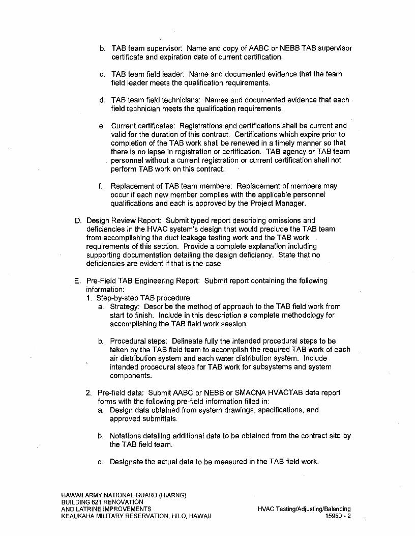
b. TAB team supervisor: Name and copy of AABC or NEBB TAB supervisor certificate and expiration date of current certification.
c. TAB team field leader: Name and documented evidence that the team field leader meets the qualification requirements.
d. TAB team field technicians: Names and documented evidence that each. field technician meets the qualification requirements.
e. Current certificates: Registrations and certifications shall be current and valid for the duration of this contract. Certifications which expire prior to completion of the TAB work shall be renewed in a timely manner so that there is no lapse in registration or certification. TAB agency or TAB team personnel without a current registration or current certification shall not perform TAB work on this contract.
f. Replacement of TAB team members: Replacement of members may occur if each new member complies with the applicable personnel qualifications and each is approved by the Project Manager.
D. Design Review Report: Submit typed report describing omissions and deficiencies in the HVAC system's design that would preclude the TAB team from accomplishing the duct leakage testing work and the TAB work requirements of this section. Provide a complete explanation including supporting documentation detailing the design deficiency. State that no deficiencies are evident if that is the case.
E. Pre-Field TAB Engineering Report: Submit report containing the following information: 1.. Step-by-step TAB procedure:
a. Strategy: Describe the method of approach to the TAB field work from start to finish. Include in this description a complete methodology for accomplishing the TAB field work session.
b. Procedural steps: Delineate fully the intended procedural steps to be taken by the TAB field team to accomplish the required TAB work of each air distribution system and each water distribution system. Include intended procedural steps for TAB work for subsystems and system components.
2. Pre-field data: Submit AABC or NEBB or SMACNA HVACTAB data report forms with the following pre-field information filled in: a. Design data obtained from system drawings, specifications, and
approved submittals.
b. Notations detailing additional data to be obtained from the contract site by the TAB field team.
c. Designate the actual data to be measured in the TAB field work.
HAWAII ARMY NATIONAL GUARD (HIARNG) BUILDING 621 RENOVATION AND LATRINE IMPROVEMENTS
HVAC Testing/Adjusting/Balancing
KEAUKAHA MILITARY RESERVATION, HILO, HAWAII
15950-2
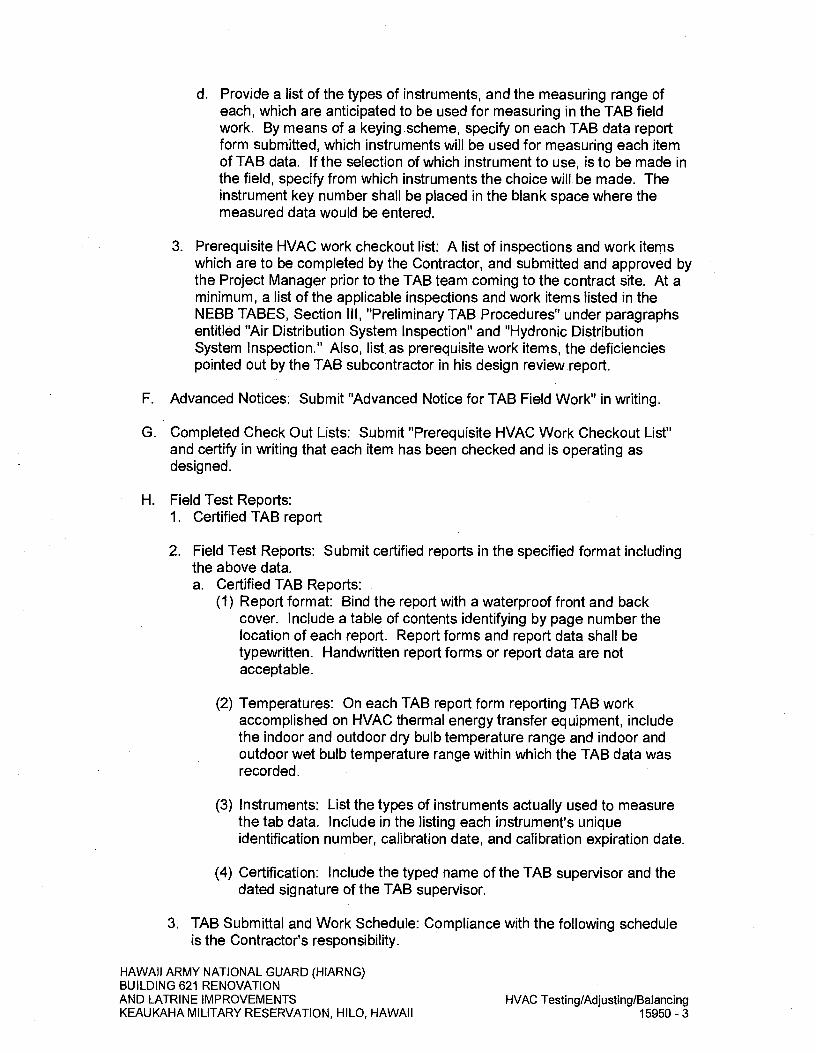
d. Provide a list of the types of instruments, and the measuring range of each, which are anticipated to be used for measuring in the TAB field work. By means of a keying scheme, specify on each TAB data report form submitted, which instruments will be used for measuring each item of TAB data. If the selection of which instrument to use, is to be made in the field, specify from which instruments the choice will. be made. The instrument key number shall be placed in the blank space where the measured data would be entered.
3. Prerequisite HVAC work checkout list: A list of inspections and work items which are to be completed by the Contractor, and submitted and approved by the Project Manager prior to the TAB team coming to the contract site. At a minimum, a list of the applicable inspections and work items listed in the NEBB TABES, Section Ill, "Preliminary TAB Procedures" under paragraphs entitled "Air Distribution System Inspection" and "Hydronic Distribution System Inspection." Also, list, as prerequisite work items, the deficiencies pointed out by the TAB subcontractor in his design review report.
F. Advanced Notices: Submit "Advanced Notice for TAB Field Work" in writing.
G. Completed Check Out Lists: Submit "Prerequisite HVAC Work Checkout List" and certify in writing that each item has been checked and is operating as designed.
H. Field Test Reports: 1. Certified TAB report
2. Field Test Reports: Submit certified reports in the specified format including the above data. a. Certified TAB Reports:
(1) Report format: Bind the report with a waterproof front and back cover. Include a table of contents identifying by page number the location of each report. Report forms and report data shall be typewritten. Handwritten report forms or report data are not acceptable.
(2) Temperatures: On each TAB report form reporting TAB work accomplished on HVAC thermal energy transfer equipment, include the indoor and outdoor dry bulb temperature range and indoor and outdoor wet bulb temperature range within which the TAB data was recorded.
(3) Instruments: List the types of instruments actually used to measure the tab data. Include in the listing each instrument's unique identification number, calibration date, and calibration expiration date.
(4) Certification: Include the typed name of the TAB supervisor and the dated signature of the TAB supervisor.
3. TAB Submittal and Work Schedule: Compliance with the following schedule is the Contractor's responsibility.
HAWAII ARMY NATIONAL GUARD (HIARNG) BUILDING 621 RENOVATION AND LATRINE IMPROVEMENTS
HVAC Testing/Adjusting/Balancing
KEAUKAHA MILITARY RESERVATION, HILO, HAWAII
15950-3
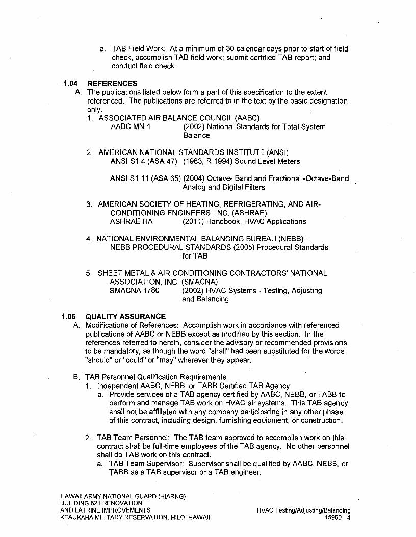
a. TAB Field Work: At a minimum of 30 calendar days prior to start of field check, accomplish TAB field work; submit certified TAB report; and conduct field check.
1.04 REFERENCES A. The publications listed below form a part of this specification to the extent
referenced. The publications are referred to in the text by the basic designation only. 1. ASSOCIATED AIR BALANCE COUNCIL (AABC)
AABC MN-1 (2002) National Standards for Total System Balance
2. AMERICAN NATIONAL STANDARDS INSTITUTE (ANSI) ANSI S1.4 (ASA 47) (1983; R 1994) Sound Level Meters
ANSI S1.11 (ASA 65) (2004) Octave- Band and Fractional -Octave-Band Analog and Digital Filters
3. AMERICAN SOCIETY OF HEATING, REFRIGERATING, AND AIR-CONDITIONING ENGINEERS, INC. (ASHRAE) ASHRAE HA (2011) Handbook, HVAC Applications
4. NATIONAL ENVIRONMENTAL BALANCING BUREAU (NEBB) NEBB PROCEDURAL STANDARDS (2005) Procedural Standards
for TAB
5. SHEET METAL & AIR CONDITIONING CONTRACTORS' NATIONAL ASSOCIATION, INC. (SMACNA) SMACNA 1780 (2002) HVAC Systems - Testing, Adjusting
and Balancing
1.05 QUALITY ASSURANCE A. Modifications of References: Accomplish work in accordance with referenced
publications of AABC or NEBB except as modified by this section. In the references referred to herein, consider the advisory or recommended provisions to be mandatory, as though the word "shall" had been substituted for the words "should" or "could" or "may" wherever they appear.
B. TAB Personnel Qualification Requirements: 1. Independent AABC, NEBB, or TABB Certified TAB Agency:
a. Provide services of a TAB agency certified by AABC, NEBB, or TABB to perform and manage TAB work on HVAC air systems. This TAB agency shall not be affiliated with any company participating in any other phase of this contract, including design, furnishing equipment, or construction.
2. TAB Team Personnel: The TAB team approved to accomplish work on this contract shall be full-time employees of the TAB agency. No other personnel shall do TAB work on this contract. a. TAB Team Supervisor: Supervisor shall be qualified by AABC, NEBB, or
TABB as a TAB supervisor or a TAB engineer.
HAWAII ARMY NATIONAL GUARD (HIARNG) BUILDING 621 RENOVATION AND LATRINE IMPROVEMENTS
HVAC Testing/Adjusting/Balancing
KEAUKAHA MILITARY RESERVATION, HILO, HAWAII
15950-4

b. TAB Team Field Leader: Leader shall have satisfactorily performed full-time supervision of TAB work in the field for not less than 3 years immediately preceding this contract's bid opening date.
c. TAB Team Field Technician: Technician shall have satisfactorily assisted a TAB team field leader in performance of TAB work in the field for not less than one year immediately preceding this contract's bid opening date.
C. Responsibilities: The Contractor shall be responsible for ensuring compliance with the requirements of this section. The following delineation of specific work responsibilities is specified to facilitate execution of the various work efforts by personnel from separate organizations. This breakdown of specific duties is specified to facilitate adherence to the schedule. 1. Contractor:
a. TAB personnel: Ensure that the TAB work is accomplished by a group meeting the requirements specified in paragraph entitled "TAB Personnel Qualification Requirements".
b. Pre-TAB meeting: Attend the meeting with the TAB Supervisor, and ensure that a representative is present for the sheetmetal contractor, mechanical contractor, and electrical contractor.
c. HVAC documentation: Furnish one complete set of the following HVAC-related documentation to the TAB Agency: (1) Contract drawings and specifications.
(2) Approved submittal data for equipment.
(3) Construction work schedule.
(4) Up-to-date revisions and change orders for the previously listed items.
(5) Submittal and work schedules: Ensure that the schedule for submittals and work required by this section are met.
d. Coordination of supporting personnel: Provide the technical personnel, such as factory representatives or HVAC controls installer required by the TAB field team to support the TAB field measurement work. Provide equipment mechanics to operate HVAC equipment to enable TAB field team to accomplish the TAB field measurement work. Ensure these support personnel are present at the times required by the TAB team, and cause no delay in the TAB field work. Conversely, ensure that the HVAC controls installer has required support from the TAB team field leader to complete the controls check out.
e. Deficiencies: Ensure that equipment defects, installation deficiencies, and design deficiencies reported by the TAB team field leader are brought to the attention of the Project Manager. Ensure that design deficiencies reported by the TAB field leader, or the TAB team
HAWAII ARMY NATIONAL GUARD (HIARNG) BUILDING 621 RENOVATION AND LATRINE IMPROVEMENTS KEAUKAHA MILITARY RESERVATION, HILO, HAWAII
HVAC Testing/Adjusting/Balancing- 15950 - 5
esting/Adjusting/Balancing15950-5

supervisor, are transmitted to the Project Manager within 4 calendar days from date of receipt from the TAB agency.
f. Prerequisite HVAC work: Complete check out and debugging of HVAC equipment, ducts, and controls prior to the TAB engineer arriving at the project site to begin the TAB work. Debugging includes searching for and eliminating malfunctioning elements in the HVAC system installations, and verifying all adjustable devices are functioning as designed. Prior to the TAB field team's arrival, ensure completion of the applicable inspections and work items listed in the TAB team supervisor's pre-field engineering report. List as prerequisite work items, the deficiencies, pointed out by the TAB team supervisor in the design review report. Ensure that the TAB Agency gets a copy of the prerequisite HVAC work checklist specified in the paragraph entitled "Submittals." Do not allow the TAB team to commence TAB field work until all of the following are completed. (1) HVAC system installations are fully complete.
(2) HVAC prerequisite checkout work lists have been completed, submitted, and approved.
(3) HVAC system filters are clean for TAB field work.
g. Advance notice: Furnish to the Project Manager with advance written notice for each event, the commencement of the field work and for the commencement of the TAB field work.
2. TAB Agency: Provide the services of a TAB team which complies with the requirements of paragraph entitled "TAB Personnel Qualification Requirements." a. TAB Team Supervisor:
(1) Overall management: Supervise and manage the overall TAB team work effort, including preliminary and technical TAB procedures and TAB team field work.
(2) Pre-TAB meeting: Attend meeting with Contractor.
(3) Design review report: Review project specifications and accompanying drawings to verify that the air systems and water systems are designed in such a way that the TAB Team Field Leader can accomplish the work in compliance with the requirements of this section. Verify the presence and location of permanently installed test ports and other devices needed, including gauge cocks, thermometer wells, flow control devices, circuit setters, balancing valves, and manual volume dampers.
(4) Support required: Specify the technical support personnel required from the Contractor other than the TAB agency; such as factory representatives for temperature controls or for complex equipment. Inform the Contractor in writing of the support personnel needed and when they are needed. Furnish the notice as soon as the need is
HAWAII ARMY NATIONAL GUARD (HIARNG) BUILDING 621 RENOVATION AND LATRINE IMPROVEMENTS
HVAC Testing/Adjusting/Balancing
KEAUKAHA MILITARY RESERVATION, HILO, HAWAII
15950-6

anticipated, either with the design review report, or the pre-field engineering report or during the TAB field work.
(5) Pre-field engineering report: Utilizing the following HVAC-related documentation; contract drawings and specifications, approved submittal data for equipment, up-to-date revisions and change orders; prepare this report.
(6) Prerequisite HVAC work checklist: Ensure the Contractor gets a copy of this checklist at the same time as the pre-field engineering report is submitted.
(7) Technical Assistance for TAB Work: Provide immediate technical assistance to the TAB field team for the TAB work.
(8) Certified TAB report: Certify the TAB report. This certification includes the following work: (a) Review: Review the TAB field data report. From this field report,
prepare the certified TAB report.
(b) Verification: Verify adherence, by the TAB field team, to the TAB plan prescribed by the pre-field engineering report and verify adherence to the procedures specified in this section.
(9) Design deficiencies: Submit in writing as soon as possible, to the Contractor and the Project Manager, each design deficiency reported by the TAB field team. Provide, in this submittal, a complete explanation -including supporting documentation detailing the deficiency.
(10) TAB Field Check: The TAB team supervisor shall attend and supervise TAB field check.
b. TAB Team Field Leader (1) Field manager: Manage, in the field, the accomplishment of the work
specified in Part 3, "Execution."
(2) Full time: Be present at the contract site when TAB field work is being performed by the TAB team; ensure day-to-day TAB team work accomplishments are in compliance with this section.
(3) Prerequisite HVAC work: Do not bring the TAB team to the contract site until a copy of the prerequisite HVAC Checklist, with all work items certified by the Contractor to be working as designed, reaches the office of the TAB Agency.
D. Re-Tab Meeting: Meet with the State's TAB representative and the designing engineer of the HVAC systems to develop a mutual understanding relative to the details of the TAB work requirements. Ensure that the TAB supervisor is present at this meeting. Requirements to be discussed include required submittals, work schedule, and field quality control.
HAWAII ARMY NATIONAL GUARD (HIARNG) BUILDING 621 RENOVATION AND LATRINE IMPROVEMENTS
HVAC Testing/Adjusting/Balancing
KEAUKAHA MILITARY RESERVATION, HILO, HAWAII
15950-7

PART 2 - PRODUCTS (Not Used)
PART 3 EXECUTION
3.01 TAB PROCEDURES A. TAB Field-Work: Test, adjust, and balance the listed HVAC systems to the state
of operation indicated on and specified in the contract design documents. Air and water systems shall be proportionately balanced and reported in the TAB report. Provide instruments and consumables required to accomplish the TAB work. Conduct TAB work on the listed HVAC systems in conformance with the AABC MN-I, or NEBB TABES, except as modified by this section: 1. Maintenance and calibration of instruments.
2. Accuracy of measurements.
3. Preliminary procedures: Test ports required for testing by the TAB engineer shall be located in the field by the TAB engineer during TAB field work. It shall be the responsibility of the sheetmetal contractor to provide and install test ports as required by the TAB engineer.
4. Air distribution systems TAB work: Air handling units, fan coil units and fans including coils, ducts, plenums, mixing boxes, and air distribution devices for supply air, return air, and outside air.
B. TAB work on performance tests: 1. Performance tests: In addition to the TAB proportionate balancing work on
the air distribution systems, accomplish TAB work on the HVAC systems which directly transfer thermal energy. TAB the operational performance of the cooling systems.
2. Ambient temperatures: On each tab report form used for recording data, record the outdoor and indoor ambient dry bulb temperature range and the outdoor and indoor ambient wet bulb temperature range within which the report form's data was recorded. That is, record these temperatures at beginning and at the end of data taking.
3.02. WORKMANSHIP A. Conduct TAB work on specified HVAC systems until measured parameters are
within plus or minus 10 percent of the design values, that is, the values specified or indicated on the contract documents. To minimize the possibility of noise at the air device, "coarse" balancing shall be performed at the duct branch and "fine" balancing shall be performed at the face of the air device.
3.03 DEFICIENCIES A. Strive to meet the intent of this section to maximize the performance of the
equipment as designed and installed. However, if deficiencies in equipment design or installation prevent TAB work from being accomplished within the range of design values specified in the paragraph entitled "Workmanship," provide written notice as soon as possible to the Contractor and the Project
HAWAII ARMY NATIONAL GUARD (HIARNG) BUILDING 621 RENOVATION AND LATRINE IMPROVEMENTS
HVAC Testing/Adjusting/Balancing
KEAUKAHA MILITARY RESERVATION, HILO, HAWAII
15950-8

Manager describing the deficiency and recommended correction. Responsibility for correction of installation deficiencies is the Contractor's. If a deficiency is in equipment design, call the TAB team supervisor for technical assistance. Responsibility for reporting design deficiencies to Contractor is the TAB team supervisor's.
3.04 DATA FROM TAB FIELD WORK A. After completion of the TAB work, prepare a pre-final TAB report. Data required
shall be furnished by the TAB team. Except as approved otherwise in writing by the Project Manager, the TAB work and the TAB report shall be considered incomplete until the TAB work is accomplished to within the accuracy range specified in the paragraph entitled 'Workmanship" of this section. Prepare the report neatly and legibly; the pre-final TAB report shall be the final TAB report minus the TAB supervisor's review and certification. Obtain, at the contract site, the TAB supervisor's review and certification of the TAB report. Verbally notify the Project Manager's TAB representative that the field check of the certified TAB report data can commence; give this verbal notice 48 hours in advance of when the field checking shall commence. Do not schedule field check of the certified TAB report until the specified workmanship requirements have been met or written approval of the deviations from the requirements have been received from the Project Manager.
3.05 QUALITY ASSURANCE FOR TAB FIELD WORK A. Field check: Test shall be made to demonstrate that capacities and general
performance of air and water systems comply with the contract requirements. 1. Recheck: During field check, the Contractor shall recheck, in the presence
of the Project Manager, random selections of data (water, air quantities, air motion, sound level readings) recorded in the certified report.
2. Areas of recheck: Points and areas of recheck shall be selected by the Project Manager.
3. Procedures: Measurement and test procedures shall be the same as approved for work for forming basis of the certified report.
4. Recheck selections: Selections for recheck will not exceed 25 percent of the total number of reported data entries tabulated in the report.
5. Retests: if random tests reveals a measured quantity which is out-of-tolerance, the report is subject to disapproval at the Project Manager's discretion. In the event the report is disapproved, all systems shall be readjusted and tested, new data recorded, new certified reports submitted, and a new field check conducted at no additional cost to the Government.
B. Approval prerequisite: Compliance with the field checking requirements of this section is a prerequisite to the final approval of the certified TAB report submitted.
3.06 MARKING OF SETTINGS A. Permanently mark the settings of HVAC adjustment devices including valves,
splitters, and dampers so that adjustment can be restored if disturbed at any
HAWAII ARMY NATIONAL GUARD (HIARNG) BUILDING 621 RENOVATION AND LATRINE IMPROVEMENTS
HVAC Testing/Adjusting/Balancing
KEAUKAHA MILITARY RESERVATION, HILO, HAWAII
15950-9

time. The permanent markings shall indicate the settings on the adjustment devices which result in the data reported on the submitted certified TAB report.
3.07 MARKING OF TEST PORTS A. The TAB team shall permanently and legibly mark and identify the location points
of the duct test ports. If the ducts have exterior insulation, these markings shall be made on the exterior side of the duct insulation. The location of test ports shall be shown on the as-built mechanical drawings with dimensions given where the test port is covered by exterior insulation.
END OF SECTION
HAWAII ARMY NATIONAL GUARD (HIARNG) BUILDING 621 RENOVATION AND LATRINE IMPROVEMENTS
HVAC Testing/Adjusting/Balancing
KEAUKAHA MILITARY RESERVATION, HILO, HAWAII
15950-10

DIVISION 16- ELECTRICAL
SECTION 16011 - GENERAL ELECTRICAL REQUIREMENTS
PART I - GENERAL
1.01 SUMMARY A. This section specifies the General Electrical Requirements for all labor, materials,
equipment and services provided under DIVISION 16 - ELECTRICAL.
1.02 WORK INCLUDED A. The Contractor under this Division shall provide all labor, materials, equipment,
supervision and services required for the construction of the electrical systems. The finished installations shall be complete, operable and shall include all work specified herein and shown on the Drawings.
B. The work shall include complete testing of all equipment and wiring at the completion of the work and making any minor connection changes or adjustments necessary for the proper functioning of the system and equipment. All systems shall be properly adjusted and in working order at the time of final acceptance.
C. All concrete, steel reinforcement, miscellaneous metal-work, earthwork, painting, and grouting shall conform to the applicable requirements of the detailed equipment specifications as prescribed in appropriate sections.
D. It is the intent of these Specifications and other Contract Documents to require an installation complete in every detail. Consequently, the Contractor will be responsible for minor details or for any special construction which may be found necessary to properly furnish, install, adjust, test, and place in successful and continuous operation, the entire electrical system including Government-furnished, Contractor installed (GFCI) equipment identified and the cost of same shall be included in the contract price.
1.03 DESCRIPTION OF WORK A. Work specified in this Division shall include, but not be limited to the following:
1. Underground utility service ductlines.
2. Distribution system, including panelboards, transformers, and feeders, including electrically related demolition work.
3. Complete electrical system wiring including branch circuits, luminaires, switches, receptacles, outlets and control devices.
4. Complete lighting and control systems, including photoelectric cell, lighting contactors, control stations, and occupancy sensors.
5. Raceways for telecommunications signal distribution systems, including CATV and administrative data sub-systems.
HAWAII ARMY NATIONAL GUARD (HIARNG) BUILDING 621 RENOVATION AND LATRINE IMPROVEMENTS
General Electrical Requirements
KEAUKAHA MILITARY RESERVATION, HILO, HAWAII
16011-1

6. Power wiring for electrically-operated equipment and appliances.
7. Testing.
1.04 REFERENCES A. Comply with the applicable requirements of the following standards unless
otherwise indicated: 1. Comply with local ordinances; National Electrical Code; applicable
regulations of the National Board of Fire Underwriters; specifications of ANSI, NEMA, UL, IES, and ICEA; and regulations of the County of Hawaii.
2. In the event of conflict between pertinent codes and regulations, and the requirements of the referenced standards, or those indicated in Specifications and on drawings, the provisions of the more stringent shall govern.
1.05 RELATED WORK A. DIVISION I - GENERAL REQUIREMENTS.
B. DIVISION 3- CONCRETE.
C. SECTION 09900 - PAINTING.
D. DIVISION 13-SPECIAL CONSTRUCTION.
E. DIVISION 15- MECHANICAL.
1.06 PERMITS AND INSPECTION A. All permits required by local ordinances shall be obtained and paid for by the
Contractor.
B. After completion of the work, the Project Manager shall be furnished a certificate of final inspection and approval from the electrical inspection department of local authority having jurisdiction.
1.07 COORDINATION A. Refer to all project Drawings and to all Sections of the project Specifications.
Coordinate and fit all work accordingly so that all electrical outlets and equipment will be properly located and readily accessible. The Drawings indicate the relation of wiring and connections and must not be scaled for exact locations. Verify all construction dimensions at the project and make changes necessary to conform to the building as constructed. Work improperly installed due to lack of construction verification shall be corrected at the Contractor's expense.
B. Work shall be scheduled to avoid delays, interferences, and unnecessary work. If any conflicts occur necessitating departures from the Drawings and Specifications, details of departures and reasons therefore shall be submitted immediately for consideration by the Project Manager.
C. Coordinate with Hawaii Electric Light Company (HELCo), Hawaiian Telcom (HT), and Spectrum for disconnection of services to building to be demolished, and installation of new building services.
HAWAII ARMY NATIONAL GUARD (HIARNG) BUILDING 621 RENOVATION AND LATRINE IMPROVEMENTS
General Electrical Requirements
KEAUKAHA MILITARY RESERVATION, HILO, HAWAII
16011-2
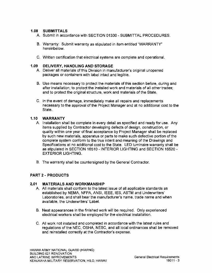
1.08 SUBMITTALS A. Submit in accordance with SECTION 01330 - SUBMITTAL PROCEDURES.
B. Warranty: Submit warranty as stipulated in item entitled "WARRANTY" hereinbelow.
C. Written certification that electrical systems are complete and operational.
1.09 DELIVERY, HANDLING AND STORAGE A. Deliver all materials of this Division in manufacturer's original unopened
packages or containers with label intact and legible.
B. Use means necessary to protect the materials of this section before, during and after installation; to protect the installed work and materials of all other trades; and to protect the original structure, work and materials of the State.
C. In the event of damage, immediately make all repairs and replacements necessary to the approval of the Project Manager and at no additional cost to the State.
1.10 WARRANTY A. Installation shall be complete in every detail as specified and ready for use. Any
items supplied by Contractor developing defects of design, construction, or quality within one year of final acceptance by Project Manager shall be replaced by such new materials, apparatus or parts to make such defective portion of the complete system conform to the true intent and meaning of the Drawings and Specifications at no additional cost to the State. LED luminaire warranty shall be as stipulated in SECTION 16510 - INTERIOR LIGHTING and SECTION 16520 - EXTERIOR LIGHTING.
B. The warranty shall be countersigned by the General Contractor.
PART 2- PRODUCTS
2.01 MATERIALS AND WORKMANSHIP A. All materials shall conform to the latest issue of all applicable standards as
established by NEMA, NFPA, ANSI, IEEE, IES, ASTM and Underwriters' Laboratories, and shall bear the manufacturer's name, trade name and when available, the Underwriters' Label.
B. Neat appearances in the finished work will be required. Only experienced electrical workers shall be employed for the electrical installation.
C. All work not installed and completed in accordance with the latest rules and regulations of the NEC, OSHA, NESC, and all local ordinances shall be removed and reinstalled correctly at the Contractor's expense.
HAWAII ARMY NATIONAL GUARD (HIARNG) BUILDING 621 RENOVATION AND LATRINE IMPROVEMENTS
General Electrical Requirements
KEAUKAHA MILITARY RESERVATION, HILO, HAWAII
16011-3
PART 3- EXECUTION
3.01 GENERAL A. Install all electrical materials and equipment in accordance with manufacturer's
recommendations and as approved by the Project Manager for the seismic zone classification at the project site.
B. Cut, break, drill and patch as required to install electrical system. Repair any surface damaged or marred by notching, drilling or any other process necessary for installation of electrical work. Patch any damaged surfaces to match the existing surface.
C. All wiring and overcurrent devices for equipment furnished by other trades are sized for a contemplated equipment size. If equipment other than contemplated and indicated on the plan is provided, the Contractor shall be responsible for providing the required wiring, switches, and overcurrent devices at no cost to the State. The Contractor shall submit the proposed revisions to the electrical design to the Project Manager for approval.
D. Coordinate work with other trades to avoid conflicts with mechanical, structural, and architectural elements of this project.
E. Follow installation and service instructions for all equipment furnished by Government for installation by the Contractor.
3.02 JOBSITE CONDITIONS A. These specifications are accompanied by construction drawings including
building and site plans of all trades showing locations of all outlets, switches, service runs, feeder runs, devices, and other electrical equipment. The locations are approximate and before installing, study adjacent architectural details and make installation in most logical manner. Any device may be relocated within 10'-0" before installation at direction of Project Manager without additional cost to State.
B. Before installing, verify all dimensions and sizes of equipment.
C. Verify that electrical system may be installed in strict accordance with the original design, the Drawings and Specifications and the manufacturer's recommendations.
D. In the event of discrepancy, immediately notify the Project Manager. Do not proceed with installation in areas of discrepancy until all such discrepancies have been fully resolved.
3.03 CONNECTIONS TO MECHANICAL AND ALL OTHER EQUIPMENT PROVIDED BY OTHER TRADES
A. Provide conduit, wiring and all electrical connections from building wiring to motors for heating, ventilation, air conditioning, and other equipment, including all switches, motor protection devices, as specified by other trades.
HAWAII ARMY NATIONAL GUARD (HIARNG) BUILDING 621 RENOVATION AND LATRINE IMPROVEMENTS
General Electrical Requirements
KEAUKAHA MILITARY RESERVATION, HILO, HAWAII
16011-4

B. Ascertain from other trades furnishing motor-driven equipment, the exact size and type of all motors, the exact locations of such equipment and the proper point where electrical connections should be brought through the floors or walls, as the case may be. Locations shown are diagrammatic only; correct locations shall be the full responsibility of the Electrical Contractor.
C. Examine Mechanical and other Drawings and Specifications for information concerning motors and control apparatus and diagrams, and for exact location of equipment outlets.
D. Install individually mounted starters furnished for motors under other Divisions. Provide and install safety switches as necessary for each such motor.
E. All control devices and control wiring shall be provided as described in the installation manuals of equipment and/or the Drawings and Specifications of other trades and disciplines.
3.04 DEMONSTRATION OF COMPLETE ELECTRICAL SYSTEMS A. Submit written certification that electrical systems are complete and operational.
Submit certification with Contractor's request for final review.
B. At the time of final review of electrical work, demonstrate the operation of electrical systems. Provide labor, apparatus and equipment for systems' demonstration. The various tests shall be under the direction and supervision of the Project Manager.
C. Provide all test equipment, materials, labor, and temporary power hook-ups to perform start-up and all tests as required to obtain final field acceptance from the State. All tests shall be conducted in the presence of the Project Manager or his representative. All test procedure shall conform to this specification and applicable standards. (ANSI, IEEE, NEMA. OSHA, NFPA, etc.)
D. A visual inspection of all electrical equipment, to check for foreign material, tightness or wiring and connection, proper grounding, matching nameplate charts with specification, etc., shall be made prior to actual testing.
E. After demonstration of systems, submit to the Project Manager 6 sets of keys for electrical equipment locks.
END OF SECTION
HAWAII ARMY NATIONAL GUARD (HIARNG) BUILDING 621 RENOVATION AND LATRINE IMPROVEMENTS
General Electrical Requirements
KEAUKAHA MILITARY RESERVATION, HILO, HAWAII
16011-5
SECTION 16100 - INTERIOR ELECTRICAL WORK
PART I - GENERAL
1.01 SUMMARY A. This section includes, but is not limited to, the following electrical work items:
1. Panelboards, transformers, overcurrent protection devices, and feeders.
2. Raceway infrastructure for telecommunication systems, including outlet boxes, junction boxes, conduits, etc.
3. Electrical work to support all power receptacles, lighting, and branch circuiting.
4. Safety switches and equipment connections.
5. Testing and completion.
1.02 RELATED WORK SPECIFIED IN OTHER SECTIONS A. SECTION 16011 - GENERAL ELECTRICAL REQUIREMENTS, applies to this
section with additions and modifications specified herein.
B. SECTION 16710 - BUILDING TELECOMMUNICATIONS CABLING SYSTEM.
1.03 APPLICABLE PUBLICATIONS A. The publications cited within this specification form a part of this specification to
the extent referenced. Unless otherwise indicated, most recent edition of the publication with current revisions and amendments will be enforced.
1.04 SUBMITTALS A. Submit in accordance with SECTION 01330 - SUBMITTAL PROCEDURES.
B. Shop Drawings: Panelboards.
C. Manufacturer's Data: 1. Panelboards.
2. Dry transformers.
3. Safety switches and enclosed circuit breakers.
4. Advance electronic meter.
5. Junction boxes with dimensions of 6 inches and larger.
D. Test Reports: Submit written notification of all interior electrical work test reports as indicated in item entitled "TESTING" hereinbelow.
HAWAII ARMY NATIONAL GUARD (HIARNG) BUILDING 621 RENOVATION AND LATRINE IMPROVEMENTS
Interior Electrical Work
KEAUKAHA MILITARY RESERVATION, HILO, HAWAII
16100-I

PART 2- PRODUCTS
2.01 GENERAL A. Materials shall be new and those items listed by the Underwriters' Laboratories
shall bear "UL" label of approval.
B. Brand names, manufacturer's names and catalog numbers indicate standard of design and quality required. Acceptable manufacturers for electrical apparatus include GE, Siemens, Square D, and Eaton. All apparatus supplied shall bear the name of the approved manufacturer on its nameplates.
C. Electrical equipment and luminaires shall be supplied through the manufacturer's designated representative by a local distributor.
D. Proof of compliance shall be furnished when shop drawings are submitted.
E. All apparatus shall be of the same manufacture.
F. Where electrical apparatus is to be installed outdoors, NEMA 3R or 4X housings shall be provided.
2.02 RACEWAYS A. Rigid Steel Conduit: Rigid steel, zinc-coated inside and outside, for use with
threaded fittings. ANSI C80.1.
B. Intermediate Metal Conduit (IMC): Rigid steel, zinc-coated inside and outside, for use with threaded fittings. UL 1242.
C. Electrical Metal Tubing (EMT): Thin walled steel tubing, zinc-coated. ANSI C80.3.
D. Flexible Metal Conduit: Flexible steel conduit; zinc-coated inside and outside, smooth inside walls, liquid-tight with factory fittings for liquid-tight installation. Provide bushings with bonding jumper lugs for flexible conduit in excess of 6 feet in length. UL 360.
E. Plastic Conduit: Polyvinyl chloride, Schedule 40.
2.03 BOXES A. Outlet and Small Junction Boxes: Nominal 4 inches square for power and non-
multi-media systems, 4-11/16 inches square for multi-media systems, 2-1/8 inches minimum depth exclusive of plaster ring, pressed steel, galvanized for corrosion protection. Exposed boxes and boxes exposed to the weather shall be cast steel, Type FS, prime painted and finished to match adjacent architectural elements.
B. Extension Rings for Outlet Boxes: Pressed steel, zinc-coated for corrosion protection.
HAWAII ARMY NATIONAL GUARD (HIARNG) BUILDING 621 RENOVATION AND LATRINE IMPROVEMENTS
Interior Electrical Work
KEAUKAHA MILITARY RESERVATION, HILO, HAWAII
16100-2
C. Large Junction Boxes (6-inches and larger): NEMA I for interior, fabricated from NEC grade steel, galvanized, primed painted and finished to match adjacent architectural elements. Exterior junction boxes shall be NEMA 4, stainless steel #302. Boxes 24-inches and larger shall have hinged door with a minimum of 2 stainless steel captive screws on the latch side of the door.
2.04 CABINETS A. Fabricated from NEC grade steel with hinged door and lockable latch, galvanized
for corrosion protection, finished to match panelboards for surface or flush mounting and size as shown on Drawings. Factory finished.
B. Signal cabinets shall be equipped with 3/4-inch thick termite treated painted plywood backboards.
C. All cabinets for power systems (i.e., panelboards, relay cabinets, etc.) shall be keyed alike. All cabinets for signal systems shall be keyed alike, but differently than power system cabinets.
2.05 CONDUCTORS A. Solid or stranded copper, sizes according to American Wire Gauge Wire, as
shown on Drawings and #12 AWG minimum unless otherwise indicated. Solid conductors only for #10 AWG and smaller. All wiring shall be color-coded.
B. Branch Circuits: Type THWN.
C. Luminaire Wires: Per NEC.
D. Conductors Larger than #8 AWG: THWN or XHHW.
E. Conductors for Equipment Connection: Stranded flexible type.
2.06 WIRING DEVICES A. Switches: Ivory, 20A, 120/277V, non-mercury quiet type specification grade with
nylon body.
B. Duplex Convenience Receptacles: Ivory, 20A, 125V, nylon body, specification grade, grounding type, unless otherwise noted. Blue body where identified on the drawings.
C. Other Receptacles: Specification grade, ratings and NEMA configurations as indicated.
D. Ground Fault Circuit Interrupters: Receptacle type similar to duplex convenience receptacle except 20A and UL listed per UL 943 with 6 milliampere ground fault sensing circuit. Feed-through type with test and reset buttons. Lock-off safety feature.
2.07 DEVICE PLATES A. Stainless steel (302) plate for all areas, unless otherwise indicated.
HAWAII ARMY NATIONAL GUARD (HIARNG) BUILDING 621 RENOVATION AND LATRINE IMPROVEMENTS
Interior Electrical Work
KEAUKAHA MILITARY RESERVATION, HILO, HAWAII
16100-3

B. For Exterior Use: Flip-open cover, high-grain non-metallic, plastic or fiberglass. Color to match adjacent finish. Cover shall be pad-lockable and capable of closing with a plug cap connected to the receptacle. Two-inch maximum projection from wall.
2.08 PANELBOARDS A. Mounting, voltage rating, main bus capacity, breaker complement and lugs as
specified on drawings, complete with housing, door, trim, lock and typewritten circuit directory. Provide copper ground bus for all panels.
B. Panelboards should have copper bussing with bolt-on, molded case circuit breakers. Provide one-inch-per-pole breakers, half-size breakers not allowed. Circuit breaker complement short circuit ratings shall be fully rated. Use of series rated equipment will not be permitted.
C. All locks shall be common-key type. Furnish 6 sets of keys to the Project Manager.
D. Panel housing and entire circuit breaker complement shall be of the same manufacture.
E. Distribution panelboards shall be 30 inches minimum width, with interchangeable trip circuit breakers and instantaneous trip adjustment.
2.09 CIRCUIT BREAKERS AND SAFETY SWITCHES A. Circuit breakers, unless otherwise shown, shall be molded case, toggle
mechanism operated, with no-fuse ambient-compensated thermal-magnetic overload automatic trip units for overcurrent and short-circuit protection, interchangeable trip units when available and contacts rated to interrupt short-circuit currents as specified on Drawings. Non-automatic breakers shall have short circuit withstand ratings as specified on Drawings. Multi-pole breakers shall have single, common operating handle for all poles.
B. Safety switches shall be heavy-duty grade, horsepower rated and sized as indicated or as to match branch circuit overcurrent device rating.
C. Enclosures for breakers and switches to be NEMA 1, for interior locations and NEMA 4X for exterior locations.
2.10 HARDWARE, SUPPORTS, BACKING, ETC. A. Provide all hardware, supports, backing and other accessories necessary to
install electrical equipment. Wood materials shall be treated against termite, iron or steel materials shall be galvanized for corrosion protection, and non-ferrous materials shall be brass or bronze.
B. Bolts, nuts, washers, and screws used for outside shall be high quality stainless steel or brass.
C. Ground Rods: Ground rods shall be copper clad steel type, 3/4-inch diameter, 10 feet long, sectional type, and conform to UL 467.
HAWAII ARMY NATIONAL GUARD (HIARNG) BUILDING 621 RENOVATION AND LATRINE IMPROVEMENTS
Interior Electrical Work
KEAUKAHA MILITARY RESERVATION, HILO, HAWAII
16100-4

2.11 DUCT SEAL A. Pliable, non-toxic material used for application around conductors in raceway and
in empty conduits to minimize moisture and rodent/insect infiltration. Must be re-enterable material allowing for removal/reapplication after initial installation. Non-drying, non-cracking, non-corrosive material that will not adversely affect raceway and conductors. Provide duct seal at all duct entries in handholes, apparatus, and risers to prevent water infiltration via duct system.
2.12 DRY TRANSFORMERS A. General: Conform to 2016 Department of Energy Efficiency Standards. Dry
transformers shall be totally metal enclosed ventilated 2 winding type, with six 2-1/2 percent taps, 2-FCAN, 4-FCBN unless otherwise noted. Temperature shall be 150 degrees C on a 220 degree C insulation system, and the transformer shall be rated and labeled for 10 percent continuous overload. Oversize or derated transformers not acceptable. Sound ratings shall not exceed NEMA ST 20 for nominal size indicated. Copper windings.
B. Vibration Mounts: All transformers shall be provided with internal vibration isolators. Transformers rated 45 kVA and larger shall be provided with external double-deflection neoprene vibration isolators with 0.4 inch static deflection between the transformer and mounting surface.
C. Transformer Connections: Provide flexible conduit connections to transformer casing for primary and secondary feeders.
2.13 ADVANCE ELECTRONIC POWER METER A. Metering: ANSI 12.10, Class 0.2S accuracy. Provide an electronic
programmable, switchboard mounted meter with integrated display, as indicated. Meter shall be either programmed at the factory or shall be programmed in the field. When field programming is performed, turn field programming device over to the Project Manager at completion of project. Meter shall be coordinated to system requirements.
B. Power meter shall be compatible for installation in the existing Square D QED switchboard. Schneider PowerLogic PM 8000 or approved equivalent.
C. Provide meter designed for use on a 3-phase, 4-wire, 480Y/277 volt system with 3 current transformers. Include necessary KYZ pulse initiation hardware for connection on the DDC (Direct Digital Control) system. Bacnet compatible.
D. Coordination: Provide meter coordinated with ratios of current transformers and transformer secondary voltage.
E. Panel instrumentation shall provide for voltage, current, frequency, power factor, minimum and maximum kW and kVA measurements.
F. Meter shall utilize time-of-use calendar to capture electrical consumption for specific times, including on/off peak and holidays.
HAWAII ARMY NATIONAL GUARD (HIARNG) BUILDING 621 RENOVATION AND LATRINE IMPROVEMENTS
Interior Electrical Work
KEAUKAHA MILITARY RESERVATION, HILO, HAWAII
16100-5

G. Meter shall have the capability to identify power quality issues per EN 50160, including frequency inconsistency, voltage fluctuations and unbalance, and harmonic contribution.
PART 3- EXECUTION
3.01 RACEWAYS A. Use conduits with approved coupling and connectors. All cuts square, using
saw. Ream the ends. Bends made with approved tools. Reject flattened or crushed conduit. No running thread. Bushing and 2 locknuts at connection to boxes and enclosures.
B. All raceways shall be blown and swabbed after installation to remove any water, then immediately sealed to prevent water and debris infiltration during construction. Raceways must remain sealed except when pulling conductors. If water is discovered during the warranty period, the Contractor shall remove water from raceways and associated boxes at no additional cost to the State.
C. Exposed conduit runs to be parallel and/or perpendicular to architectural and structural elements. Galvanized rigid steel conduit or IMC up to 7 feet above finished interior floor and for all outdoor locations including the underside of covered walkways and crawl spaces. EMT permitted for exposed installation indoors above 7 feet. EMT also permitted for exposed installation throughout dedicated electrical rooms, except where routed up through grade slab.
D. Electrical Metallic Tubing (EMT): Acceptable for exposed, indoor installation as indicated above and for all concealed indoor installations with the following exceptions: 1. EMT not permitted in/under grade slab.
2. EMT not permitted in walls that are in contact with earth.
3. Provide factory-made transitions between rigid conduit and EMT. Use only compression type, concrete tight couplings.
4. Field-paint exposed tubing with corrosion-resistant paint.
E. Non-metallic conduits only permitted for exterior ductlines and beneath grade slab at building; within retaining walls in contact with earth up to the first outlet box or conduit coupling above the height of earth being retained; and within walls anchored to grade slab and not in contact with earth up to height of first outlet box or conduit coupling. Exposed installation of non-metallic conduit not permitted.
F. Minimum conduit diameter shall be 3/4-inch trade size except that 1/2-inch conduit will be permitted for branch circuit (non-signal) raceways with a maximum of 2 current carrying conductors #10 AWG and smaller.
HAWAII ARMY NATIONAL GUARD (HIARNG) BUILDING 621 RENOVATION AND LATRINE IMPROVEMENTS
Interior Electrical Work
KEAUKAHA MILITARY RESERVATION, HILO, HAWAII
16100-6

G. Provide nylon pullstring of 200-pound minimum tensile strength in all empty conduits in excess of 15 feet in length.
H. Conceal all raceways unless otherwise noted on the drawings.
I. Conduits crossing expansion joints shall be provided with appropriate couplings or flexible conduit jumpers as required to accommodate a one-inch movement between structural elements in all horizontal directions from the static, design position.
3.02 UTILITY SYSTEMS A. Telephone and TV/Data System:
1. Provide an empty conduit system for telephone, TV, and data consisting of pullwire, conduits, cabinets, and main grounding.
2. Provide a nylon pullstring or muletape in all empty ducts and conduits. Provide 12 inches of tagged slack at backboards and cabinets.
3. Coordinate with telecommunications service vendor for all requirements, schedule, inspections, and service dates with Hawaiian Telcom (HT) and Spectrum.
3.03 BOXES A. Plumb and securely fasten. Flush boxes - exactly flush; apply form oil so that
stray concrete can be removed readily. Remove all debris from interior.
B. Install boxes serving opposite sides of walls a minimum of 6 inches apart to minimize noise transmission.
C. Provide 2-device plaster reducing trim ring for 4-11/16-inch by 2-1/8-inch minimum depth multimedia outlet boxes. Single device trim rings will not be acceptable. Provide outlet box covers as shown on plans for multimedia outlet boxes.
D. All outlet boxes must be cleaned of debris prior to cable installation.
3.04 CONDUCTORS A. Lubricants: Non-wax type, chemically neutral to insulation and sheath.
Mechanical means for pulling to be torque-limiting type and not be used for #2 AWG and smaller wires.
B. No-solder pressure connectors or crimp connections for #8 AWG and larger wires. Remove all sharp points that can pierce tape. Reinsulate according to wire manufacturer's directions.
C. Clean all raceways, boxes, and enclosures before pulling wires and cables. Form neatly in enclosures for minimum of cross-overs.
HAWAII ARMY NATIONAL GUARD (HIARNG) BUILDING 621 RENOVATION AND LATRINE IMPROVEMENTS
Interior Electrical Work
KEAUKAHA MILITARY RESERVATION, HILO, HAWAII
16100-7
D. Cables used for electronic equipment shall be clearly and permanently tagged to show junction and destination. Cables shall be pulled and fastened securely so as to avoid sharp bends and prevent rubbing against sharp corners and shall be fastened to suitable hardware in a manner to prevent injury or physical distortion of cable. Splices, fittings, and connectors shall be indicated on the system layout to facilitate system servicing.
3.05 MISCELLANEOUS DETAILS A. Provide necessary foundations, supports, backing, etc., for all raceways and
equipment. Attach to wood and steel by screws or bolts. Attach to concrete by expansion anchors. Powder charge driven studs and anchors shall not be used.
B. Clean all surfaces of enclosures and equipment.
C. Close all unused knockout holes.
3.06 PAINTING A. Wipe clean of dirt, oil, grease, etc., with rag and solvent, prime and finish to
match surrounding finish. Do not paint over nameplate. Paint as specified in SECTION 09900 - PAINTING.
B. All surface-mounted boxes, enclosures, exposed raceways, and signal backboards shall be painted to match the color of surrounding building finishes.
C. Do Not field-paint circuit breakers, panelboards, dry transformers, and safety switches.
3.07 IDENTIFICATION A. All overcurrent protection devices, enclosures, and cabinets shall be provided
with plastic plate identifying itself and its use. 1. Identify all panelboards, switchboard breakers, self-contained breakers, and
safety switches where not mounted on equipment.
2. Time Switches, Contactors, Cabinets and Junction boxes 12 inches and larger in any dimension. (i.e. RELAY "2A", "Time Switch")
B. Plastic plate shall be laminated black and white, engraved 1/4-inch high lettering to expose black layer. Identification plates for emergency system shall be laminated red and white plastic plate. Plate shall be riveted to the cover and located directly below device handle, or top side of door.
C. CAUTION SIGNS shall be provided as required by Ordinances and/or by OSHA.
3.08 TESTING A. Upon completion of this portion of work, and prior to its acceptance by the State,
make all required tests and secure all required approval from agencies having jurisdiction. Any deficiencies found shall be rectified and work affected by such deficiencies shall be completely retested at Contractor's expense. Written notification of all proposed tests shall be provided to the Project Manager a minimum of 14 days prior to the date of the test.
HAWAII ARMY NATIONAL GUARD (HIARNG) BUILDING 621 RENOVATION AND LATRINE IMPROVEMENTS
Interior Electrical Work
KEAUKAHA MILITARY RESERVATION, HILO, HAWAII
16100-8
B. Perform an operational test after completion of the installation in the presence of the Project Manager, to assure proper operation of all items of work. Remove all grounds and shorts. Balance feeder loads.
END OF SECTION
HAWAII ARMY NATIONAL GUARD (HIARNG) BUILDING 621 RENOVATION AND LATRINE IMPROVEMENTS
Interior Electrical Work
KEAUKAHA MILITARY RESERVATION, HILO, HAWAII
16100-9

SECTION 16302 - ELECTRICAL SITE WORK
PART I - GENERAL
1.01 SUMMARY A. This section included, but is not limited to, the following items:
1. Underground electrical and lighting distribution system for the renovated facilities.
2. Underground telecommunication distribution system for the renovated facilities.
1.02 RELATED WORK SPECIFIED IN OTHER SECTIONS A. SECTION 16011 - GENERAL ELECTRICAL REQUIREMENTS applies to this
section with additions and modifications specified herein.
1.03 APPLICABLE PUBLICATIONS A. The publications cited within this specification form a part of this specification to
the extent referenced. Unless otherwise indicated, most recent edition of the publication with current revisions and amendments will be enforced.
1.04 SUBMITTALS A. Submit in accordance with SECTION 01330-SUBMITTAL PROCEDURES.
B. Manufacturer's Data and Shop Drawings: 1. Conduit.
2. Precast handholes, including frames and covers.
3. Warning tape.
C. Manufacturer's Instructions: 1. Manufacturer's directions for use of ground megger with proposed method
indicated.
2. Typical installation instructions for splicing.
D. Certificates: 1. Material and Equipment: Provide manufacturer's statement certifying that the
product supplied meets or exceeds contract requirements.
E. Test Reports: Submit test reports as stipulated in item entitled "FIELD TESTS" hereinbelow.
HAWAII ARMY NATIONAL GUARD (HIARNG) BUILDING 621 RENOVATION AND LATRINE IMPROVEMENTS
Electrical Site Work
KEAUKAHA MILITARY RESERVATION, HILO, HAWAII
16302-1

PART 2- PRODUCTS
2.01 MATERIALS AND EQUIPMENT A. Materials and equipment shall conform to the respective specifications and
standards and to the specifications herein. Electrical ratings shall be as indicated. 1. Conduit:
a. Rigid Metal Conduit: UL 6, hot-dip galvanized, threaded type.
b. Rigid Plastic Conduit: UL 651, Schedule 40, PVC.
2. PVC Fittings: UL 651.
3. Tape: UL 510. Plastic insulating tape shall be capable of performing in a continuous temperature environment of 80 degrees C.
4. Power Wire and Cable: a. Wire and cable conductor sizes are designated by American Wire Gauge
(AWG).
b. Conductors shall be copper. Insulated conductors shall bear the date of manufacture imprinted on the wire insulation with other identification. Wire and cable manufactured more than 6 months before delivery to the job site shall not be used.
c. Provide conductor identification within each enclosure where a tap, a splice or a termination is made.
d. Use No. 10 minimum sized conductors, unless otherwise noted.
e. For underground telecommunications system cabling, see SECTION 16710 - BUILDING TELECOMMUNICATIONS CABLING SYSTEM.
5. Wire Conformation: Cables shall be type XHHW-2 conforming to NEMA WC-7 and UL 44 or type USE conforming to NEMAWC-7 and UL 854.
6. Connector and Terminals: Wire connectors and terminals for use with copper conductors shall conform to UL 486A.
7. Pullstring: a. Pullstring shall be plastic rope having a minimum tensile strength of 200
pounds in each empty duct except those intended for telephone cabling.
b. For empty ducts intended for telecommunications cabling, provide mule tape in conformance with telephone utility company standards.
8. Grounding and Bonding Equipment: Shall conform to UL 467.
HAWAII ARMY NATIONAL GUARD (HIARNG) BUILDING 621 RENOVATION AND LATRINE IMPROVEMENTS
Electrical Site Work
KEAUKAHA MILITARY RESERVATION, HILO, HAWAII
16302-2
9. Underground Structures: a. Precast Handholes: Handholes, including metal frames and covers, shall
be the type noted on the drawings and shall be constructed in accordance with the applicable details as indicated and required by reference utility company standard drawings. Top, walls, and bottom shall consist of reinforced concrete. Walls and bottom shall be of monolithic concrete construction. Covers shall fit the frames without undue play. Steel and iron shall be formed to shape and size with sharp lines and angles. Castings shall be free from warp and blow holes that may impair their strength or appearance. Exposed metal shall have a smooth finish and sharp lines and arises. Provide all necessary lugs, rabbets, and brackets. Set pulling-in irons and other built-in items in place before depositing concrete. A pulling-in iron shall be installed in the wall opposite each duct line entrance. Cable racks, including rack arms and insulators, shall be adequate to accommodate the cables provided by Contractor and the respective utility companies.
10. Warning Tape: Pre-printed polyethylene, 4 mil minimum thick, 3 inches minimum width, detectable foil backed, color-coded. For utility ductlines, provide per utility company standards.
11. Duct Seal: Pliable, non-toxic material used for application around conductors in raceway and in empty conduits to minimize moisture and rodent/insect infiltration. Must be re-enterable material allowing for removal/reapplication after initial installation. Non-drying, non-cracking, non-corrosive material that will not adversely affect raceway and conductors. Provide duct seal at all duct entries in handholes, apparatus, and risers to prevent water infiltration via duct system.
PART 3- EXECUTION
3.01 INSTALLATION A. Underground cable installation shall conform to NFPA 70 and ANSI C2.
1. Concrete: Concrete for electrical requirements shall be at least 2500 psi concrete with one-inch maximum aggregate conforming to the requirements of DIVISION 3- CONCRETE.
2. Earthwork: Excavation, backfilling, and pavement for repairs for electrical requirements shall conform to the requirements of DIVISION 2 - SITE CONSTRUCTION.
3. Underground Duct with Concrete Encasement: Construct underground duct lines of individual conduits encased in concrete. The conduit shall be of PVC. The concrete encasement surrounding the bank shall be rectangular in cross-section and shall provide at least 3 inches of concrete cover for ducts. Separate conduits by a minimum concrete thickness of 2 inches, except separate light and power conduits from control, signal, and telephone conduits by a minimum concrete thickness of 3 inches.
HAWAII ARMY NATIONAL GUARD (HIARNG) BUILDING 621 RENOVATION AND LATRINE IMPROVEMENTS
Electrical Site Work
KEAUKAHA MILITARY RESERVATION, HILO, HAWAII
16302-3

a. Duct lines shall have a continuous slope downward toward hand holes and away from buildings with a pitch of not less than 3 inches in 100 feet. Except at conduit risers, accomplish changes in direction of runs exceeding a total of 10 degrees, either vertical or horizontal, by long sweep bends having a minimum radius of curvature of 25 feet. Sweep bends may be made up of one or more curved or straight sections or combinations thereof. Manufactured bends shall have a minimum radius of 18 inches for use with conduits of less than 3 inches in diameter and a minimum radius of 36 inches for ducts of 3 inches in diameter and larger.
b. Separators shall be of precast concrete, high impact polystyrene, steel, or any combination of these. Stagger the joints of the conduits by rows and layers so as to provide a duct line having the maximum strength. During construction, protect partially completed duct lines from the entrance of debris such as mud, sand and dirt by means of suitable conduit plugs. As each section of duct line is completed from handhole to handhole, draw a brush through having the same diameter of the duct, and having stiff bristles until the conduit is clear of all particles of earth, sand, and gravel; then immediately install conduit plugs.
4. Cable Pulling: Pull cables down grade with the feed-in point at the handhole or buildings of the highest elevation. Use flexible cable feeds to convey cables through the handhole opening and into the duct runs. Cable slack shall be accumulated at each handhole or junction box where space permits by training the cable around the interior to form one complete loop. Minimum allowable bending radii shall be maintained in forming such loops. a. Lubricants for assisting in the pulling of jacketed cables shall be those
specifically recommended by the cable manufacturer. The lubricant shall not be deleterious to the cable sheath, jacket, or outer coverings.
b. Cable pulling tensions shall not exceed the maximum pulling tension recommended by the cable manufacturer.
c. Secondary cable runs, 600 volts and less, shall include an insulated copper equipment grounding conductor sized as indicated.
d. Installation of Cables in Hand holes: Do not install cables utilizing the shortest route, but route along those walls providing the longest route and the maximum spare cable lengths. Form all cables to closely parallel walls and not to interfere with duct entrances. In existing hand holes where new cables are to be installed, modify the existing installation of cables, cable supports and grounding as required for a neat and workmanlike installation with all cables properly arranged and supported.
5. Cable Terminating: Protect terminations of insulated power and lighting cables from accidental contact, deterioration of coverings and moisture by the use of terminating devices and materials. Install all terminations of insulated power and lighting cables and cable splices in accordance with the manufacturer's requirements. Make terminations using materials and methods as indicated or specified herein or as designated by the written instructions of the cable manufacturer and termination kit manufacturer.
HAWAII ARMY NATIONAL GUARD (HIARNG) BUILDING 621 RENOVATION AND LATRINE IMPROVEMENTS
Electrical Site Work
KEAUKAHA MILITARY RESERVATION, HILO, HAWAII
16302-4
a. Splices for 600 Volt Class Cables: Make splices in underground systems only in accessible locations such as handholes, using a compression connector on the conductor and by insulating and waterproofing by one of the following methods suitable for continuous submersion in water. 1) Provide cast-type splice insulation by means of molded casting
process employing a thermosetting epoxy resin insulating material and apply by a gravity poured method or by a pressure injected method. The component materials of the resin insulation shall be in a packaged form ready for convenient mixing without removing from the package. Do not allow the cables to be removed until after the splicing material has completely set.
2) Gravity poured method shall employ materials and equipment contained in an approved commercial splicing kit which includes a mold suitable for cables to be spliced. When the mold is in place around the joined conductors, prepare the resin mix and pour into the mold. Do not allow cables to be moved until after the splicing materials have completely set.
3) Heat Shrinkable method shall employ materials and equipment contained in an approved commercial splicing kit.
6. Grounding: a. Non-current carrying metallic parts associated with electrical equipment
shall have a maximum resistance to solid "earth" ground not exceeding the following values: 1) Grounds in handholes 10 ohms
2) Grounded secondary distribution system neutral and non-current carrying metal parts associated with distribution systems and grounds not otherwise covered 25 ohms
When work in addition to that indicated or specified is directed in order to obtain the specified ground resistance, the provisions of the contract covering "Changes" shall apply.
b. Grounding electrodes shall be cone pointed driven ground rods driven full depth less 6 inches, installed when indicated to provide an earth ground of the value before stated for the particular equipment being grounded.
c. Make grounding connections which are buried or otherwise normally inaccessible, and excepting specifically those connections for which access for periodic testing is required by exothermite type process. Make therm it welds strictly in accordance with the weld manufacturer's written recommendations. Welds which have "puffed up" or which show convex surfaces indicating improper cleaning are not acceptable. No mechanical connector is required at thermit weldments.
HAWAII ARMY NATIONAL GUARD (HIARNG) BUILDING 621 RENOVATION AND LATRINE IMPROVEMENTS
Electrical Site Work
KEAUKAHA MILITARY RESERVATION, HILO, HAWAII
16302-5

d. In lieu of an exothermic type process, a compression ground grid connector of a type which uses hydraulic compression tool to provide the correct circumferential pressure may be used. Tools and dies shall be as recommended by the manufacturer. An embossing die code or other standard method shall provide visible indication that a connector has been adequately compressed on the ground wire.
e. Grounding conductors shall be bare soft-drawn copper wire No. 6 AWG minimum unless otherwise indicated or specified.
7. Provide all empty conduits with a plastic pullstring or mule tape. Leave 48 inches of spare at each end of the pull.
3.02 UNDERGROUND FEEDER IDENTIFICATION A. Cables shall be labeled at both ends and in handholes in the following format:
X-Y-POWER where "X" represents the source building, "Y" represents the destination building and "POWER" represents Power cable.
3.03 FIELD TESTS A. Distribution Conductors 600 Volt Class: Test all 600 volt class conductors #1/0
AWG and larger to verify that no short circuits or accidental grounds exist. Make tests using an instrument which applies a voltage of approximately 500 volts to provide a direct reading in resistance.
B. Ground Rods: Test ground rods for ground resistance value before any wire is connected. Use a portable ground testing megger to test each ground or group of grounds. The instrument shall be equipped with a meter reading directly in ohms or fractions thereof to indicate the ground value of the ground electrode under test. Provide one copy of the megger manufacturer's directions for use of the ground megger indicating the method to be used.
C. Test Report: Provide 3 copies of each test report to the Project Manager. 1. 600-volt cables (identify each cable and test result).
2. Grounding Electrodes and Systems (identify electrodes and systems, each test).
END OF SECTION
HAWAII ARMY NATIONAL GUARD (HIARNG) BUILDING 621 RENOVATION AND LATRINE IMPROVEMENTS
Electrical Site Work
KEAUKAHA MILITARY RESERVATION, HILO, HAWAII
16302-6

SECTION 16510 - INTERIOR LIGHTING
PART I - GENERAL
1.01 SUMMARY A. This section includes, but is not limited to, interior luminaires, drivers, lighting
controls, and emergency lighting units, and all required components and accessories.
1.02 RELATED WORK A. SECTION 16011 - GENERAL ELECTRICAL REQUIREMENTS applies to this
section, with the additions and modifications specified herein.
1.03 APPLICABLE PUBLICATIONS A. The publications listed below form a part of this specification to the extent
referenced. The publications may be referred to in the text by the basic designation only. Unless otherwise indicated, most recent edition of the publication with current revisions and amendments will be enforced.
1.04 DESCRIPTION OF WORK A. The work includes providing luminaires, switches, photoelectric cells, contactors,
and battery-powered units and systems for interior use, including luminaires and accessories mounted on the exterior surfaces of buildings. Materials not normally furnished by manufacturers of these devices are specified in SECTION 16100 - INTERIOR ELECTRICAL WORK.
1.05 SUBMITTALS A. Submit in accordance with SECTION 01330 - SUBMITTAL PROCEDURES.
B. Data, shop drawings, and reports shall employ the terminology, classifications, and methods prescribed by the IES Lighting Handbook, as applicable, for the lighting system specified.
C. Manufacturer's Catalog Data: 1. Luminaires, including lamps and drivers
2. Occupancy sensors
3. Lighting control system room controllers
4. Lighting control system control switches
5. Lighting control relay panels, control stations and diagrams.
6. Lighting contactors
7. Photoelectric cell
HAWAII ARMY NATIONAL GUARD (HIARNG) BUILDING 621 RENOVATION AND LATRINE IMPROVEMENTS
Interior Lighting
KEAUKAHA MILITARY RESERVATION, HILO, HAWAII
16510-1

8. Exit lights
9. Emergency lighting equipment
D. Shop Drawings: 1. Lighting control system schematic connection diagrams.
2. Lighting control relay panels, control stations and diagrams.
E. O&M Manual: Submit Operations and Maintenance Manual as stipulated in item entitled "OPERATIONS AND MAINTENANCE MANUAL" hereinbelow.
F. Warranty: LED lighting fixtures shall carry a minimum manufacturer's warranty of 5 years. The Surety will not be held liable beyond 2 years from the project acceptance date.
1.06 OPERATIONS AND MAINTENANCE MANUAL A. Submit operation and maintenance data showing all light fixtures, control
modules, control zones, occupancy sensors, light level sensors, power packs, schematic diagrams and all interconnecting control wire, conduit, and associated hardware. Submit documentation that includes contact information, summary of procedures, and the limitations and conditions applicable to the project.
PART 2- PRODUCTS
2.01 LED LIGHTING FIXTURES A. Provide lighting fixtures specifically engineered for LED light sources and drivers.
Use of linear or screw-base retrofit LED light sources is not acceptable.
B. LED Light Sources: 1. Correlated Color Temperature (CCT) shall be in accordance with NEMA
ANSLG C78.377: Nominal CCT: 3500 degrees K unless otherwise specified.
2. Color Rendering Index (CRI) shall be greater than or equal to 80 unless otherwise indicated.
C. Luminaire LED Power Supply Units (Drivers): 1. LED Power Supply Units (Drivers): UL 1310. LED Power Supply Units
(Drivers) shall meet the following requirements: a. Minimum efficiency shall be 80 percent.
b. Shall be designed to operate on the voltage system to which they are connected, typically ranging from 120 V to 480 V nominal.
c. Operating frequency shall be 60 Hz.
d. Power Factor (PF) shall be greater than or equal to 0.90.
HAWAII ARMY NATIONAL GUARD (HIARNG) BUILDING 621 RENOVATION AND LATRINE IMPROVEMENTS
Interior Lighting
KEAUKAHA MILITARY RESERVATION, HILO, HAWAII
16510-2

e. Total Harmonic Distortion (THD) current shall be less than or equal to 20 percent.
f. Shall be mounted integral to luminaire. Remote mounting of power supply is not allowed.
g. Power supplies in luminaires shall be UL listed with a sound rating of
h. Where indicated, drivers shall be dimmable, and compatible with a standard dimming control circuit of 0 - I OV or other approved dimming system as indicated.
i. Shall be equipped with over-temperature protection circuit that turns light source off until normal operating temperature is achieved.
2.02 RECESS- AND FLUSH-MOUNTED FIXTURES A. Provide type that can be relamped from the bottom. Access to drivers shall be
from the bottom. Trim for the exposed surface of flush-mounted fixtures shall be as indicated. Delete thermal insulation immediately surrounding recessed luminaires.
2.03 SUSPENDED FIXTURES A. Provide hangers capable of supporting twice the combined weight of fixtures
supported by hangers. Provide with swivel hangers to ensure a plumb installation. Hangers shall be cadmium-plated steel with a swivel-ball tapped for the conduit size indicated. Hangers shall be shock-absorbing type where indicated. Hangers shall allow fixtures to swing within an angle of 45 degrees. Brace pendants 4 feet or longer to limit swinging with a 2-way bracing system. Single-unit suspended fixtures shall have twin-stem hangers. Multiple-unit or continuous row fixtures shall have a tubing or stem for wiring at one point and a tubing or rod suspension provided for each unit length of chassis, including one at each end. Rods shall be a minimum 1/4-inch diameter.
2.04 LIGHTING CONTACTOR A. NEMA ICS 2, electrically held contactor. Rate contactor as indicated. Provide in
NEMA I enclosure conforming to NEMA ICS 6. Contactor shall have silver alloy double-break contacts. Provide contactor with hand-off-automatic selector switch.
2.05 PHOTOELECTRIC CELL A. UL 773 or UL 773A, hermetically sealed cadmium-sulfide or silicon diode type
cell rated 120 volts ac, 60 Hz with single-throw contacts. Switch shall turn on at or below 3 footcandles and off at 2 to 10 footcandles. A time delay shall prevent accidental switching from transient light sources. Provide switch: 1. In a U.V. stabilized polycarbonate housing with swivel arm and adjustable
window slide, rated 1800 VA, minimum.
2. In a high-impact-resistant, noncorroding and nonconductive molded plastic housing with a locking-type receptacle conforming to NEMA C136.10, rated 1800 VA, minimum.
HAWAII ARMY NATIONAL GUARD (HIARNG) BUILDING 621 RENOVATION AND LATRINE IMPROVEMENTS
Interior Lighting
KEAUKAHA MILITARY RESERVATION, HILO, HAWAII
16510-3
2.06 LIGHTING CONTROL RELAY PANEL A. Lighting control relay panels shall be UL listed, with surface mounted NEMA I
enclosure. Door shall be hinged and lockable with internal barrier for separation of high voltage (Class 1) and low voltage (Class 2) wiring. It shall include intelligence boards, power supply and control relays. Clock display and keypad shall be mounted on interior cabinet door for easy user access and programming. The lighting control panel shall have the following features: I. Panel shall accept up to 24 single pole relays, unless otherwise indicated.
Relays shall be individual latching relays with 20 Amp load contacts for LED drivers and general purpose loads. Relays shall use quick connectors and be individually replaceable to facilitate ease of use.
2. The lighting control panel shall provide a stagger up delay, override push buttons, and LED status light indicators for each relay or contactor control channel.
3. The clock shall have a backlight display, user keypad and shall provide 8 channels of time or astronomical control. Preprogrammed lighting control scenarios shall include: scheduled on/off, manual on/scheduled off, manual on/automatic switch sweep off, astronomic on/off and astronomic control with scheduled on/off. Time clock shall provide up to 42 holidays, automatic daylight savings adjustment, astronomic coordinates by major cities, and help screens. Program memory shall be non-volatile and clock shall retain time keeping during power outages for at least 48 hours.
4. The panel shall have 8 universal switch inputs that are low voltage, self-configuring and shall not require programming to accept momentary on/momentary off switch, push button switch (cycling), maintained switch or 24 VDC signals from occupancy sensors or other interfacing devices.
5. Occupancy sensor and time control shall be integrated to allow occupancy sensor control after hours with hold on of lighting during occupancy scheduled time. During occupied time, control scenarios shall be selectable for time schedule of lighting on or occupancy sensor detection of lighting on initially and then hold on of lighting during occupied hours. Control shall provide adjustable occupancy sensor time delay from the time clock keypad.
6. Each panel shall support RS232 twisted pair and optional RS-485 connections. Either protocol may be used for programming, monitoring, and control. The dataline shall allow simultaneous operation of multiple communications access points to support multiple operator terminals. Each panel shall be capable of stand-alone automatic operation and the network shall achieve full distributed processing.
2.07 LIGHTING CONTROL STATIONS A. Lighting control stations shall be compatible with the lighting control relay panels
or other room controller devices, low voltage type, ivory color with matching faceplate. Provide number of zones indicated and engrave or provide permanent nameplates to identify function.
HAWAII ARMY NATIONAL GUARD (H1ARNG) BUILDING 621 RENOVATION AND LATRINE IMPROVEMENTS
Interior Lighting
KEAUKAHA MILITARY RESERVATION, HILO, HAWAII
16510-4

2.08 OCCUPANCY SENSORS A. UL listed. Comply with GC-12. Occupancy sensors and power packs shall be
designed to operate on the voltage indicated. Sensors and power packs shall have circuitry that only allows load switching at or near zero current crossing of supply voltage. Occupancy sensor mounting as indicated. Sensor shall have an LED occupant detection indicator. Sensor shall have adjustable sensitivity and adjustable delayed-off time range of 5 minutes to 15 minutes. Wall mounted sensors shall be white, ceiling mounted sensors shall be white. Ceiling mounted sensors shall have 360 degree coverage unless otherwise indicated. 1. Ultrasonic sensor shall be crystal controlled and shall not cause detection
interference between adjacent sensors.
2. Infrared sensors shall have a daylight filter. Sensor shall have a fresnel lens that is applicable to space to be controlled.
3. Ultrasonic/Infrared Combination Sensor: Occupancy detection to turn lights on requires both ultrasonic and infrared sensor detection. Lights shall remain on if either the ultrasonic or infrared sensor detects movement. Infrared sensor shall have lens selected for indicated usage and daylight filter to prevent short wavelength infrared interference. Ultrasonic sensor frequency shall be crystal controlled.
4. Wallbox sensors shall provide a nominal range of coverage of 900 square feet when mounted at 4 feet above the floor with a 180 degree field of view.
5. Ceiling- or wall-mounted sensors shall provide a nominal range of coverage of 1000 square feet with ceiling heights of 8 to 12 feet.
2.09 EXIT LIGHTS A. UL 924, NFPA 70, and NFPA 101. Exit lights shall be self-powered type. Exit
lights shall use no more than 5 watts.
B. Self-Powered LED Type Exit Lights (Battery Backup): Provide with automatic power failure device, test switch, pilot light, and fully automatic high/low trickle charger in a self-contained power pack. Battery shall be sealed electrolyte type, shall operate unattended, and require no maintenance, including no additional water, for a period of not less than 5 years. LED exit light shall have emergency run time of 90 minutes (minimum). The light emitting diodes shall have rated lamp life of 70,000 hours (minimum).
2.10 EMERGENCY LIGHTING EQUIPMENT A. UL 9247 NFPA 70, and NFPA 101.
1. Emergency Lighting Unit: Provide as indicated.
2.11 SUPPORT HANGERS FOR LIGHTING FIXTURES IN SUSPENDED CEILINGS A. Wires: ASTM A641/A641M, galvanized regular coating, soft temper, 0.1055
inches in diameter (12 gage).
B. Wires, for Humid Spaces: 1. ASTM A580/A580M, composition 302 or 304, annealed stainless steel 0.1055
inches in diameter (12 gage).
HAWAII ARMY NATIONAL GUARD (HIARNG) BUILDING 621 RENOVATION AND LATRINE IMPROVEMENTS
Interior Lighting
KEAUKAHA MILITARY RESERVATION, HILO, HAWAII
16510-5

2. ASTM 13164, UNS N04400, annealed nickel-copper alloy 0.1055 inches in diameter (12 gage).
C. Rods: Threaded steel rods, 1/4-inch diameter, zinc or cadmium coated.
PART 3- EXECUTION
3.01 INSTALLATION A. Electrical installations shall conform to IEEE 02, NFPA 70, and to the
requirements specified herein.
B. Lighting Fixtures: Set lighting fixtures plumb, square, and level with ceiling and walls, in alignment with adjacent lighting fixtures, and secure in accordance with manufacturers' directions and approved drawings. Installation shall meet requirements of NFPA 70. Mounting heights specified or indicated shall be to the bottom of fixture for ceiling-mounted fixtures and to center of fixture for wall-mounted fixtures. Obtain approval of the exact mounting for lighting fixtures on the job before commencing installation and, where applicable, after coordinating with the type, style, and pattern of the ceiling being installed. Recessed and semi-recessed fixtures shall be independently supported from the building structure by a minimum of 4 wires or threaded rods per fixture and located near each corner of each fixture. Ceiling grid clips are not allowed as an alternative to independently supported light fixtures. Round fixtures or fixtures smaller in size than the ceiling grid shall be independently supported from the building structure by a minimum of 4 wires or threaded rods per fixture spaced approximately equidistant around the fixture. Do not support fixtures by ceiling acoustical panels. Where fixtures of sizes less than the ceiling grid are indicated to be centered in the acoustical panel, support such fixtures independently and provide at least two 3/4 inch metal channels spanning, and secured to, the ceiling tees for centering and aligning the fixture. Provide wires or threaded rods for lighting fixture support in this section.
C. Suspended Fixtures: Suspended fixtures shall be provided with 45 degree swivel hangers so that they hang plumb and shall be located with no obstructions within the 45 degree range in all directions. The stem, canopy and fixture shall be capable of 45 degree swing. Pendants, rods, or chains 4 feet or longer excluding fixture shall be braced to prevent swaying using 3 cables at 120 degree separation. Suspended fixtures in continuous rows shall have internal wireway systems for end to end wiring and shall be properly aligned to provide a straight and continuous row without bends, gaps, light leaks or filler pieces. Aligning splines shall be used on extruded aluminum fixtures to assure hairline joints. Steel fixtures shall be supported to prevent "oil-canning" effects. Fixture finishes shall be free of scratches, nicks, dents, and warps, and shall match the color and gloss specified. Pendants shall be finished to match fixtures. Aircraft cable shall be stainless steel. Canopies shall be finished to match the ceiling and shall be low profile unless otherwise shown. Maximum distance between suspension points shall be 10 feet or as recommended by the manufacturer, whichever is less.
HAWAII ARMY NATIONAL GUARD (HIARNG) BUILDING 621 RENOVATION AND LATRINE IMPROVEMENTS
Interior Lighting
KEAUKAHA MILITARY RESERVATION, HILO, HAWAII
16510-6

D. Exit Lights and Emergency Lighting Units: Wire exit lights and emergency lighting units ahead of the switch to the normal lighting circuit located in the same room or area.
E. Occupancy Sensor: Provide quantity of sensor units indicated as a minimum. Provide additional units to give full coverage over controlled area. Full coverage shall provide hand and arm motion detection for office and administration type areas and walking motion for storage rooms and hallways. Locate the sensor(s) as indicated and in accordance with the manufacturer's recommendations to maximize energy savings and to avoid nuisance activation and deactivation due to sudden temperature or airflow changes and usage. Set sensor "on" duration to 10 minutes.
3.02 FIELD APPLIED PAINTING A. Paint electrical equipment as required to match finish of adjacent surfaces or to
meet the indicated or specified safety criteria. Painting shall be as specified in SECTION 09900 - PAINTING.
3.03 GROUNDING A. Ground noncurrent-carrying parts of equipment as specified in SECTION 16100 -
INTERIOR ELECTRICAL WORK. Where the copper grounding conductor is connected to a metal other than copper, provide specially treated or lined connectors suitable for this purpose.
3.04 FIELD TESTS A. Operating Test: Upon completion of the installation, conduct an operating test to
show that the equipment operates in accordance with the requirements of this section. Make adjustments and add and/or replace light fixtures and other equipment as required to correct deficiencies. Lighting level measurements shall be provided upon request and be made at intervals as directed by the Project Manager and with a NIST calibrated cosine corrected photometer with a silicon photodiode.
B. Lighting Control Test: Conduct operational control of installed and energized luminaires. Set time delays and aim as directed by Project Manager.
C. Ground Resistance Tests: Perform as specified in SECTION 16100 - INTERIOR ELECTRICAL WORK.
END OF SECTION
HAWAII ARMY NATIONAL GUARD (HIARNG) BUILDING 621 RENOVATION AND LATRINE IMPROVEMENTS
Interior Lighting
KEAUKAHA MILITARY RESERVATION, HILO, HAWAII
16510-7

SECTION 16520 - EXTERIOR LIGHTING
PART I - GENERAL
1.01 SUMMARY A. This section includes, but is not limited to, luminaires, light pole assemblies,
lamps and drivers.
1.02 RELATED WORK A. SECTION 16011 - GENERAL ELECTRICAL REQUIREMENTS applies to this
section, with the additions and modifications specified herein.
B. SECTION 16100 - INTERIOR ELECTRICAL WORK applies to this section, with additions and modifications specified herein.
C. SECTION 16302 - ELECTRICAL SITE WORK.
D. Luminaires and accessories mounted on exterior surfaces of buildings are specified in SECTION 16510 - INTERIOR LIGHTING.
1.03 APPLICABLE PUBLICATIONS A. The publications listed within this specification form a part of this specification to
the extent referenced. The publications are referred to in the text by the basic designation only. Unless otherwise indicated, most recent edition of publication with current revisions and amendments will be enforced.
1.04 DESCRIPTION OF WORK A. The work includes providing luminaires and light pole assemblies. Materials not
normally furnished by manufacturers of these devices are specified in SECTION 16100 - INTERIOR ELECTRICAL WORK and SECTION 16302 - ELECTRICAL SITE WORK.
1.05 SUBMITTALS A. Submit in accordance with SECTION 01330 - SUBMITTAL PROCEDURES.
B. Data, shop drawings, and reports shall employ the terminology, classifications, and methods prescribed by the IES Lighting Handbook, as applicable, for the lighting system specified.
C. Manufacturer's Data: 1. Luminaires and drivers.
2. Light pole assemblies including dimensions, accessories, installation and construction details.
3. Photometric Data and Illumination Calculations: Submit illumination calculations for the parking lot using the proposed luminaire. The calculations shall be plotted on 11 inches by 17 inches or 24 inches by 36 inches paper and shall include summary tables. The summary tables shall include the luminaire description and calculation results. Calculations shall
HAWAII ARMY NATIONAL GUARD (HIARNG) BUILDING 621 RENOVATION AND LATRINE IMPROVEMENTS
Exterior Lighting
KEAUKAHA MILITARY RESERVATION, HILO, HAWAII
16520-1
include maintain minimum, average, and maximum footcandle levels. Calculations shall also include maximum/minimum and average/minimum uniformity ratios. Point-to-point footcandle value shall be provided at 10 feet on center. Calculations shall utilize a 0.85 light loss factor.
D. Warranty: LED lighting fixtures shall carry a minimum manufacturer's warranty of 5 years. The Surety will not be held liable beyond 2 years from the project acceptance date.
PART 2- PRODUCTS
2.01 LED LUMINAIRES A. Provide lighting fixtures specifically engineered for LED light sources and drivers.
Use of linear or screw-base retrofit LED light sources is not acceptable.
2.02 LED LIGHT SOURCES A. Correlated Color Temperature (CCT) shall be in accordance with NEMAANSLG
C78.377: Nominal CCT: 5000 degrees K unless otherwise specified.
B. Color Rendering Index (CRI) shall be greater than or equal to 80.
C. Color Consistency: Manufacturer shall utilize a maximum 4-step MacAdam ellipse binning tolerance for color consistency of LEDs used in luminaires.
2.03 LED POWER SUPPPLY UNITS (DRIVERS) A. Per ULI3IO.
B. LED Power Supply Units (Drivers) shall meet the following requirements. 1. Minimum efficiency shall be 85 percent.
2. Shall be rated to operate between ambient temperatures of minus 22 degrees F and 104 degrees F.
3. Shall be designed to operate on the voltage system to which they are connected, typically ranging from 120 V to 480 V nominal.
4. Operating frequency shall be 60 Hz.
5. Power Factor (PF) shall be greater than or equal to 0.90.
6. Total Harmonic Distortion (THD) current shall be less than or equal to 20 percent.
7. Shall be mounted integral to luminaire. Remote mounting of power supply is not allowed.
8. Power supplies in luminaires shall be UL listed with a sound rating of A.
9. Shall be equipped with over-temperature protection circuit that turns light source off until normal operating temperature is achieved.
HAWAII ARMY NATIONAL GUARD (HIARNG) BUILDING 621 RENOVATION AND LATRINE IMPROVEMENTS
Exterior Lighting
KEAUKAHA MILITARY RESERVATION, HILO, HAWAII
16520-2

2.04 LIGHT POLE ASSEMBLIES A. Provide light pole assemblies conforming to requirements indicated on the
drawings.
PART 3- EXECUTION
3.01 INSTALLATION A. Light Pole Assemblies:
1. Before trenching or excavating, structural outlines and center lines of ductlines and light pole foundations shall be clearly staked, and approval received from the Project Manager. Staking shall be with steel or wood pegs or paint.
2. Light pole shafts shall be field adjusted for vertical alignment.
3. After pole is set, grease ends of all anchor bolts.
4. All tapped holes and stainless steel screws shall be sprayed with "Thread-Eze" by Chemsearch prior to assembling, shipping, or installation. Grease all exposed screws and bolts.
5. Pole, base covers, luminaires, etc., shall be handled in a manner that will preserve the overall appearance and prevent damage to the coating. The use of chains, cables or unprotected forks is prohibited. Only non-abrasive nylon rope or equivalent nylon belting will be allowed (3/4-inch diameter minimum). Adequate hold-downs and appropriate blocking shall be utilized for shipping to prevent load movement and damage to the outer coating in transit.
3.02 GROUNDING A. Ground noncurrent-carrying parts of equipment as specified in SECTION 16100 -
INTERIOR ELECTRICAL WORK and SECTION 16302 - ELECTRICAL SITE WORK. Where the copper grounding conductor is connected to a metal other than copper, provide specially treated or lined connectors suitable for this purpose.
3.03 FIELD TESTS A. Operating Test: Upon completion of the installation, conduct an operating test to
show that the equipment operates in accordance with the requirements of this section. Make adjustments and add and/or replace light fixtures and other equipment as required to correct deficiencies. Any deficiencies shall be rectified, and work affected shall be completely retested, at no additional cost to the State.
B. Test for continuity of each circuit.
C. Megger test each lighting circuit to certify that the circuits are free from short circuits and grounds.
HAWAII ARMY NATIONAL GUARD (HIARNG) BUILDING 621 RENOVATION AND LATRINE IMPROVEMENTS
Exterior Lighting
KEAUKAHA MILITARY RESERVATION, HILO, HAWAII
16520-3

D. A functional test in which it is demonstrated that each and every part of the system functions as specified or as intended herein. The Contractor shall test the system for 6 hours with all lights burning, then turn it off for one minute, then on again to check for faulty lights.
END OF SECTION
HAWAII ARMY NATIONAL GUARD (HIARNG) BUILDING 621 RENOVATION AND LATRINE IMPROVEMENTS
Exterior Lighting
KEAUKAHA MILITARY RESERVATION, HILO, HAWAII
16520-4

SECTION 16710 - BUILDING TELECOMMUNICATIONS CABLING SYSTEM
PART 1- GENERAL
1.01 SUMMARY A. Work in this section includes the structured cabling system for the
telecommunication systems which shall be provided for this project. Work includes, but is not limited to, the passive cabling infrastructure, pathways and spaces to support the building telecommunication systems specified herein.
1.02 APPLICABLE PUBLICATIONS A. The publications cited within this specification form a part of this specification to
the extent referenced. Unless otherwise indicated, most recent edition of the publication with current revisions and amendments will be enforced.
1.03 DEFINITIONS A. Apparatus: Generally used herein to include the inter-building cable system,
station wiring, cable racks, wiring and equipment frames, cross connect equipment and wiring adapters, information outlets and faceplates, designation strips, materials, supplies or whatsoever that may be purchased, together with the usual appropriate fittings, attachments, appurtenances, and appliances required for the intended operation.
B. Work Specification: The technical specification describing the Scope of Work, including the engineering, furnishing, delivery, installation and testing of the telecommunication wiring system.
C. Intra-Building Wiring System: A wiring system, which includes necessary apparatus, providing communications within a building.
D. Inter-Building Wiring System: A wiring system, which includes necessary apparatus, providing communications between more than one building.
E. Backbone Distribution System: The part of the premise distribution system that provides connection between equipment rooms, telecommunication rooms, telecommunication enclosures, and telecommunication entrance facilities.
F. Horizontal Distribution System: The part of the premise distribution system that provides connection between the horizontal cross connect point within the equipment and/or telecommunications room and the work area.
1.04 SYSTEM DESCRIPTIONS A. Telecommunications structured cabling system will be utilized to support voice
(telephone), data, and CATV connections within the new facility. The structured cabling system shall consist of entrance facilities for utility services, telecommunication rooms, inter-building and intra-building backbone distribution systems, and horizontal distribution systems to support the new facility. Materials not normally furnished by manufacturers of these devices are specified in SECTION 16100 - INTERIOR ELECTRICAL WORK and SECTION 16302 - ELECTRICAL SITE WORK.
HAWAII ARMY NATIONAL GUARD (HIARNG) BUILDING 621 RENOVATION AND LATRINE IMPROVEMENTS
Building Telecommunications Cabling System
KEAUKAHA MILITARY RESERVATION, HILO, HAWAII
16710-1

B. In addition, project will provide empty pathways with pullstring to facilitate the future installation of Electronic Security System (ESS) equipment and devices by others within the HIARNG portion of the renovated facility. ESS pathways for the HIARNG renovated portion of the facility shall include Access Control System (ACS), Intrusion Detection System (IDS), and Closed Circuit Television System (CCTV).
1.05 SUBMITTALS A. Submit in accordance with SECTION 01330 - SUBMITTAL PROCEDURES.
B. Telecommunications Shop Drawings: 1. Telecommunications System Drawings and Diagrams.
2. Telecommunications Floorplans/Space Drawings.
3. Telecommunications Details.
C. Manufacturer's Data: 1. Telecommunications Cabling and Connectors.
2. Termination Equipment, including patch panels and termination blocks.
3. Telecommunication Outlets, including outlet box, faceplates, and connectors/jacks.
4. Telecommunications Backboard.
5. Telecommunications Grounding Busbar.
D. Qualifications: Telecommunications Contractor
E. Test Plan/Reports: Telecommunication system cabling testing plan and test reports.
F. Record Documentation.
G. Labeling: Telecommunications system infrastructure administration/identification labeling scheme.
H. Warranty: Submit warranty as stipulated in item entitled "WARRANTY" herein below.
1.06 MANUFACTURER'S STANDARD OF QUALITY A. It is the intent of these specifications and applicable drawings to identify the
essential requirements related to the telecommunications wiring system and the quality of materials, construction, design, and overall workmanship. All manufacturers shall meet these minimum requirements.
HAWAII ARMY NATIONAL GUARD (HIARNG) BUILDING 621 RENOVATION AND LATRINE IMPROVEMENTS
Building Telecommunications Cabling System
KEAUKAHA MILITARY RESERVATION, HILO, HAWAII
16710-2

B. All products referenced in this section may be substituted with a product of the same or better operating specifications if substitution is submitted and approved in accordance with the requirements of the Special Provisions. Contractor shall list all apparatus or materials substitutions, and provide sufficient product information or specifications, to illustrate product is equivalent to those specified herein.
C. Products from Other Manufacturers: The products of other manufacturers that meet or exceed the material, construction, and standard of quality specified hereinafter shall be submitted for approval in accordance with the substitution request requirements set forth in DIVISION I - GENERAL REQUIREMENTS and the requirements below: I. Manufacturers requesting substitution approval shall submit evidence of at
least two (2) years experience manufacturing the type of products covered in this specification. Catalogs and technical data identifying conformance to the specifications shall be submitted for substitution approval.
2. The acceptance of any other manufacturer's product shall not relieve the Contractor of his responsibility for providing a complete and functioning voice and data wiring system.
1.07 QUALITY ASSURANCE A. Brand names, manufacturer's names and catalog numbers indicate a standard of
design and quality required. Acceptable manufacturers for telecommunication apparatus include Belden, BerkTek/Ortronics, Blonder Tongue, Corning, CommScope/Systimax, Leviton, Pass & Seymour, Siemon, Suttle, and Tyco Electronics (TE) Connectivity. All apparatus supplied shall bear the name of the approved manufacturer of its nameplates. Substitute materials may be used if pre-qualified prior to bidding by the Project Manager.
B. Cabling, equipment, and hardware manufactures shall have a minimum of three (3) years experience in the manufacturing, assembly, and factory testing of components which comply with ANSI/TIA/EIA-568-C. I, ANSI/TIA/EIA-568-C.2, and ANSIITIA/EIA-568-C.3.
C. Preparation of shop drawings and submittals shall be done under the supervision of a BICSI Registered Communications Distribution Designer (RCDD). RCDD shall be currently employed as a member of the Contractor's staff. Sub-contracting personnel with RCDD accreditation is not acceptable.
D. All Contractor personnel shall be fully trained and qualified to perform tasks associated with the installation, termination and testing of UTP and fiber optic cable including but not limited to fusion splicing, fiber optic connector termination and the proper operation of cabling test devices (i.e. Pentascanner).
E. Supervisors and installers assigned to the installation of this system or any of its components shall be BICSI Registered Cabling Installers, Technician Level. In lieu of BISCI certification, supervisors and installers assigned to the installation of this system or any of its components shall have a minimum of three (3) years experience in the installation of the specified copper and fiber optic cable and components. They shall have factory or factory approved certification indicating
HAWAII ARMY NATIONAL GUARD (HIARNG) BUILDING 621 RENOVATION AND LATRINE IMPROVEMENTS
Building Telecommunications Cabling System
KEAUKAHA MILITARY RESERVATION, HILO, HAWAII
16710-3

that they are qualified to install and test the provided products. Submit documentation for a minimum of three (3) and a maximum of five (5) successful system installations provided that are equivalent in system size and in construction complexity to the telecommunication system proposed for this project. Include specific experience in installing and testing telecommunication systems and provide names and locations of at least two project installations successfully completed using optical fiber and copper telecommunication cabling systems. Contractor shall submit a list of personnel qualified to perform such activities for bid evaluation.
1.08 SHOP DRAWINGS A. Contractor shall provide RCDD approved shop drawings in accordance with
ANSI/TIA/EIA-606-A. As a minimum, the Contractor shall provide the following drawings: I. TI - Building Floorplans with Building Area/Serving Zone Boundaries and
Entrance Facilities: Drawing shall indicate the location of the entrance facilities, telecommunication spaces, serving zones, vertical backbone distribution diagrams, access points, pathways, grounding system and other systems that need to be viewed from the complete building perspective.
2. T2 - Serving Zones / Building Area Drawings - Drop Locations and Cable Identification (ID's): Enlarged plan showing building area or serving zone. These drawings show drop locations, telecommunication spaces, access points and detail call outs for common equipment rooms and other congested areas.
3. T3 - Telecommunication Space Drawings: Detailed layout of Telecommunication Spaces: Provide telecommunication space drawings which as a minimum include telecommunications room plan views, pathway layouts (cable tray, racks, equipment cabinets, etc.), mechanical/electrical utility support layout, rack/cabinet elevations, and backboard elevations. Drawings shall show layout of applicable equipment including incoming cable connector blocks, space for building protectors, outgoing cable connector blocks, patch panels, equipment spaces, and cabinet/racks. Drawings shall also include a complete list of equipment and material, equipment rack/cabinet details, proposed layout and anchorage of equipment and appurtenances, and equipment relationship to other parts of work including clearance for maintenance and operation.
4. T4 - Typical Detail Drawings: Detailed drawings of symbols and typical details for faceplate labeling/identification, faceplate types, faceplate population installation procedures, detail racking and raceways.
1.09 RECORD DOCUMENTATION A. In addition to the standard close out documentation, Contractor shall provide 15
drawings including documentation on installed cables and termination hardware in accordance with ANSI/TIA/EIA-606-A. T5 drawings shall include schedules to show information for cutovers and cable plant management, patch panel layouts and cover plate assignments, cross-connect information and connecting terminal layout as a minimum. Provide hard copy documentation for the following T5 drawings as a minimum:
HAWAII ARMY NATIONAL GUARD (HIARNG) BUILDING 621 RENOVATION AND LATRINE IMPROVEMENTS
Building Telecommunications Cabling System
KEAUKAHA MILITARY RESERVATION, HILO, HAWAII
16710-4
1. Cables: A record of installed cables shall be provided in accordance with ANSI/TIA/EIA-606-A. The cable records shall include only the required data fields in accordance with ANSI/TIA/EIA-606-A. Included manufacture date of cable with submittal.
2. Termination Hardware: A record of installed patch panels, cross-connect points, distribution frames, terminating block arrangements and type, and outlets shall be provided in accordance with ANSI/TIA/EIA-606-A. Documentation shall include the required data fields, as a minimum, in accordance with ANSI/TIA/EIA-606-A.
1.10 WARRANTY A. General Warranty: Special warranty specified in this Article shall not deprive The
State of other rights The State may have under other provisions of the Contract Documents and shall be in addition to, and run concurrent with, other warranties made by Contractor under requirements of the Contract Documents.
B. Contractor shall warrant the installation and provide an application/manufacturer's warranty in addition to the standard Installation, Workmanship, and Equipment Warranty. 1. Application/Manufacturer's Warranty: Contractor shall provide an
Application/Manufacturer's warranty to the State. This warranty guarantees that any application up to 1Gbps will run on this wiring system for a period of at least 20 years. As an example, Commscope (Systimax Solutions) offers the SYSTIMAX product's exclusive SYSTIMAX 20-year product and applications warranty. Contractor shall register the installation with the manufacturer to secure such extended warranties and assurances.
2. Installation Warranty: Contractor shall warrant to the State that the installation, workmanship, equipment, and/or material to be furnished herein shall be new and free from defects in material and workmanship for a period of no less than two (2) years from the date of project acceptance; and will be of the kind and quality designated or described herein and shall perform in the manner set forth in the Contract. At time of acceptance, Contractor shall guarantee that the State shall be in sole ownership and title to all materials and equipment, which shall be free of any encumbrance or claims imposed by a third party.
C. If it appears within two years from the date of project acceptance, and/or title passage that the installation, workmanship, equipment and/or material furnished hereunder does not meet the warranties specified above and the State notifies the Contractor promptly, the Contractor shall thereupon correct any defect, including non-conformance with the Contract, without delay and expense to the State.
D. If Contractor is obliged to correct defects as specified above, the warranty period for the repaired or replacement part shall be warranted for the remaining warranty term, as determined by the original date of acceptance.
E. The State shall also be entitled to all Manufacturer's warranties and guarantees associated with the apparatus or materials provided by the Contractor.
HAWAII ARMY NATIONAL GUARD (HIARNG) BUILDING 621 RENOVATION AND LATRINE IMPROVEMENTS
Building Telecommunications Cabling System
KEAUKAHA MILITARY RESERVATION, HILO, HAWAII
16710-5

F. The Surety shall not be liable beyond 2 years from the project acceptance date.
PART 2- PRODUCTS
2.01 GENERAL A. All telecommunications infrastructure, including the horizontal and backbone
distribution infrastructure and associated hardware shall be provided in accordance with ANSI/TIA/EIA-568-C. 1, ANSI/TIA/EIA-568-C.2, ANSI/TIA/EIA-568-C.3, ANSI/TIA/EIA-569-B, NFPA 70, Department of the Army Technical Criteria for the Installation Information Infrastructure Architecture (13A), applicable UL standards, and all local state/county government standards/regulations as applicable.
2.02 COMPONENTS A. UL or third party certified. Provide a complete system of the telecommunications
cabling and pathway components using a hierarchical star topology and support structures, pathways and spaces complete with conduits, cable trays, pull wires, terminal boxes, outlets, cables, junction boxes, and backboards. Fixed cables and pathway systems for telecommunication systems shall be UL listed or third party independent testing laboratory certified, and shall comply with NFPA 70.
2.03 PATHWAYS (BACKBONE AND HORIZONTAL) A. ANSI/TIA-569-B and Addenda. Interior pathways shall consist of conduit
distribution system as specified in SECTION 16100 - INTERIOR ELECTRICAL WORK. Exterior (inter-building) pathways shall consist of underground ductlines and. handholes as specified in SECTION 16302 - ELECTRICAL SITE WORK. Provide grounding and bonding as required by the National Electrical Code (NFPA 70) and TIA J-STD-607-A.
B. Work Area Pathways: Provide minimum one (1) 1"C between each information outlet location and the nearest communications distribution junction box or telecommunications room. Comply with the National Electrical Code (NFPA 70) and ANSI/TIA-569-13 and Addenda.
C. Innerduct: UL 2024. Innerduct for interior installations shall be thin wall corrugated Polyvinyl chloride (PVC), riser or plenum rated in accordance with NFPA 70, sized as noted, 0.035" minimum wall thickness, orange, integral pullstring/mule tape. Carlon Riser-Gard, Carlon Plenum-Gard or approved equivalent.
D. Fabric Mesh Innerduct: Provide multi-cell, stiff, fabric mesh innerduct with pullstring in exterior distribution. Multi-cell fabric mesh shall have uninterrupted, shared, sewn spline to prevent twisting. Innerduct shall be installed in accordance with manufacturer's recommendation and their standard installation practices. Provide a minimum of three (3) sets of three (3) inch - three (3)_ cell innerduct within each 4-inch conduit designated for innerduct unless otherwise indicated on contract documents.
HAWAII ARMY NATIONAL GUARD (HIARNG) BUILDING 621 RENOVATION AND LATRINE IMPROVEMENTS
Building Telecommunications Cabling System
KEAUKAHA MILITARY RESERVATION, HILO, HAWAII
16710-6

E. Cable Runways. UL Listed. Tubular steel cable runway with flat black powder coat finish. Runway shall be ladder type with 1 1/2-inch stringer height with welded rungs. Stringer side rail shall conform to the minimum chemical and mechanical properties of ASTM A513 Grade 1008 steel. Cable runway rungs shall be constructed of ASTM A101 1 SS Grade 33 structural steel. Each rung shall be 1/2-inch by 1-inch steel c-channel shape with radiused edges. Runway shall be sized as noted on the drawings. Cable runways shall be supported at no more than 5-ft on center. Cable runways only used in telecommunications equipment rooms and telecommunications rooms.
2.04 TELECOMMUNICATIONS CABLING INFRASTRUCTURE A. Cabling shall be UL listed for the application and shall comply with ANSI/TIA/EIA-
568-C.1, ANSI/TIA/EIA-568-C.2, ANSI/TIA/EIA-568-C.3 and NFPA 70. Provide a labeling system for cabling as required by ANSI/TIA/EIA-606-A and UL 969. Cabling manufactured more than 12 months prior to date of installation shall not be used.
B. Backbone Cabling: 1. Inter-Building (Exterior) Backbone Optical Fiber Cabling: ANSI/TIA/EIA-
492AAAB, ANSI/TIA/EIA-492CAAA, ANSI/TIA/EIA-568-C.3, UL 1666, and NFPA 70. Ultraviolet (UV) resistant, flame-retardant outer cable jacket shall be imprinted with the fiber count, fiber type, and aggregate length at regular intervals not to exceed 40-inches. The cable cordage jacket, fiber, unit, and group color shall be in accordance with ANSI/TIA/EIA-598-C. Cables shall utilize gel-free waterblocking technology and be suitable for installation within exterior underground duct applications and in wet locations. a. Single mode optical fiber, 8/125-micron outdoor rated, gel-free, loose-
tube fiber optic cable with a nonconductive optical fiber plenum (OFNP) or a nonconductive optical fiber riser (OFNR) rating in accordance with NFPA 70. Type OFNP cable may be substituted for type OFNR cables.
b. Multi-mode optical fiber, 0M3 laser optimized 50/125-micron, outdoor rated, gel-free, loose-tube fiber optic cable with a nonconductive optical fiber plenum (OFNP) or a nonconductive optical fiber riser (OFNR) rating in accordance with NFPA 70. Type OFNP cable may be substituted for type OFNR cables. Multi-mode fiber shall conform to 0M3 cable transmission performance parameters identified within ANSI/TIA-568-C.3.
2. I ntra-Build ing Backbone Optical Fiber Cabling: ANSI/TIA/EIA-492AAAB, ANSI/TIA/EIA-492CAAA, ANSI/TIA/EIA-568-C.3, UL 1666, NFPA 70. Ultraviolet (UV) resistant, flame-retardant outer cable jacket shall be imprinted with the fiber count, fiber type, and aggregate length at regular intervals not to exceed 40-inches. The cable cordage jacket, fiber, unit, and group color shall be in accordance with ANSI/TIA/EIA-598-C. When installed on exterior or underground, cables shall utilize gel-free waterbiocking technology and be suitable for installation within exterior underground duct applications and in wet locations. a. Single mode optical fiber, 8/125-micron, tight-buffered fiber optic cable
with a nonconductive optical fiber plenum (OFNP) or a nonconductive optical fiber riser (OFNR) rating in accordance with NFPA 70. Type OFNP cable may be substituted for type OFNR cables.
HAWAII ARMY NATIONAL GUARD (HIARNG) BUILDING 621 RENOVATION AND LATRINE IMPROVEMENTS
Building Telecommunications Cabling System
KEAUKAHA MILITARY RESERVATION, HILO, HAWAII
16710-7
b. Multi-mode optical fiber, 0M3 laser optimized 50/125-micron, tight-buffered fiber optic cable with a nonconductive optical fiber plenum (OFNP) or a nonconductive optical fiber riser (OFNR) rating in accordance with NFPA 70. Type OFNP cable may be substituted for type OFNR cables. Multi-mode fiber shall conform to 0M3 cable transmission performance parameters identified within ANSI/TIA-568-C. 3.
3. Inter-Building (Exterior) Telephone Backbone/Riser Cabling: Solid copper conductors, covered with an extruded solid insulating compound. Insulated conductors shall be twisted into pairs which are then stranded or oscillated to form cylindrical core. Cable shall be completed by the application of a suitable core wrapping material, a corrugated copper or plastic coated aluminum shield, and an overall extruded jacket. Telecommunications contractor shall verify distances and between any required splice points prior to ordering cable in specific cut lengths. Provide filled cable meeting the requirements of ICEA S-99-689 and RUS 1755.390 and be suitable for installation within exterior underground duct applications and in wet locations.
C. Horizontal Cabling: 1. Horizontal Voice/Data Cabling: Comply with NFPA 70, NEMA WC 63.1,
ICEA S-90-661 and performance characteristics in ANSI/TIA/EIA-568-C. 1. Horizontal UTP cabling shall not exceed 295-feet of cabling distance between the horizontal cross-connect point and the communications outlet at work area. Horizontal CATV cabling shall not exceed 200-feet of cabling distance between CATV backboard and the CATV outlets. a. Horizontal UTP Voice Copper: ANSI/TIA/EIA-568-C.2, NFPA 70, UTP
(unshielded twisted pair), 100-ohm. Provide four each individually twisted pair, minimum 24 AWG conductors, Category-6, plenum (CMP) rated with a green PVC jacket.
b. Horizontal UTP Data Copper: ANSI/TIA/EIA-568-C.2, NFPA 70, UTP (unshielded twisted pair), 100-ohm. Provide four each individually twisted pair, minimum 24 AWG conductors, Category-6, plenum (CMP) rated with a blue PVC jacket.
2.05 TELECOMMUNICATIONS OUTLET BOXES A. As specified in SECTION 16100 - INTERIOR ELECTRICAL WORK and as
clarified herein. Standard telecommunications back box shall be double gang, 4 11/16-inches square by 2 1/8-inches deep, unless specified otherwise. Telecommunications outlet box for wall telephone CATV, and CCTV outlets shall be single gang, 2-inches by 4-inches by 2 1/4-inches deep. Provide with reducer ring for all outlets installed within new walls. Depth of boxes shall be large enough to allow manufacturers' recommended conductor bend radii.
B. Mount outlets flush in all new finished walls at height specified for outlet receptacles. Surface mount outlets on existing finished walls at height specified for outlet receptacles. Paint all surface mounted conduits and outlet boxes to match surrounding finishes.
HAWAII ARMY NATIONAL GUARD (HIARNG) BUILDING 621 RENOVATION AND LATRINE IMPROVEMENTS
Building Telecommunications Cabling System
KEAUKAHA MILITARY RESERVATION, HILO, HAWAII
16710-8

2.06 TELECOMMUNICATIONS OUTLET/CONNECTOR ASSEMBLIES A. Outlet/Connector UTP Copper: Outlet/connectors shall comply with FCC Part
68.5, ANSI/TINE lA-568-C. I and ANSI/TIA/EIA-568-C.2. 1. Telephone/Data outlet/connectors shall be ULI 863 listed, non-keyed, 8-pin
modular, constructed of high impact rated thermoplastic housing and shall be third party verified and shall comply with ANSI/TINEIA-568-C.2 Category-6 requirements. Outlet/connectors provided for UTP cabling shall meet or exceed the requirements for the cable provided. Outlet/connectors shall be terminated using a Type 110 IDC PC board connector, color-coded for both T568A and T568B wiring. Each outlet/connector shall be wired T568A. UTP outlet/connectors shall comply with ANSI/TINE IA-568-C.2 for 200 mating cycles. Provide green outlet/connector for voice positions and blue outlet/connector for data positions.
B. Cover Plates: Telecommunications cover plates shall comply with UL 514C, ANSI/TINEIA-568-C. 1, ANSI/TINEIA-568-C.2, and ANSI/TINE lA-568-C.3; flush design constructed of 430 stainless or brass material as indicated. Faceplates for standard telecommunications outlet shall be double-gang with minimum of six (6) RJ-ports. Faceplates for CATV and CCTV outlets shall be single gang. Faceplate for wall telephone outlet shall be single gang with instrument mounting tabs to support wall mounted telephone instrument. Stenciled lettering for voice and data circuits shall be provided using thermal ink transfer, process.
C. Optical Fiber Connectors: EIA/TIA-455-21-A. Optical fiber connectors shall be duplex SC, epoxyless crimp style compatible with fiber optic cable to which it will be terminated. The connectors shall utilize a zirconia ceramic ferrule. The connectors shall provide a maximum attenuation of 0.3 dB @ 1300 nm with less than a 0.2 dB change after 500 mating cycles.
D. 110 Connector Blocks: Provide insulation displacement connector (lDC) Type 110 for Category Se and higher systems. Provide blocks for the number of horizontal and backbone cables terminated on the block plus 25 percent spare. Terminal blocks shall meet or exceed the requirements for the cable provided.
E. UTP Copper Patch Panels: Provide in accordance with ANSI/TINEIA-568-C.1 and ANSI/TINEIA-568-C.2. Panels shall be third party verified and shall comply with EINTIA Category 6 requirements. Panels shall be constructed of 0.09-inch minimum aluminum and shall be rack mounted and compatible an EIA compliant 19-inch equipment rack. Panel shall provide 24 or 48 non-keyed, 8-pin modular ports, wired to T568A. Patch panels shall terminate the building cabling on Type 110 lDCs and shall utilize a printed circuit board interface. The rear of each panel shall have incoming cable strain-relief and routing guides. Panels shall have each port factory numbered and be equipped with laminated plastic nameplates above each port. Patch panel shall meet or exceed the requirements for the cable provided.
F. Optical Fiber Patch Panels: Provide panel for maintenance and cross-connect of optical fiber cables. Panel shall be constructed of 18-gauge steel or 11-gauge aluminum minimum and shall be rack mounted and compatible with an EIA compliant 19-inch equipment rack. Each panel shall support a minimum of 12-strands configured as 12 multi-mode or single mode adapters as duplex "SC" in
HAWAII ARMY NATIONAL GUARD (HIARNG) BUILDING 621 RENOVATION AND LATRINE IMPROVEMENTS
Building Telecommunications Cabling System
KEAUKAHA MILITARY RESERVATION, HILO, HAWAII
16710-9

accordance with ANSI/TIA/EIA-604-3A with zirconia ceramic alignment sleeves. Provide dust cover for unused adapters. The rear of each panel shall have a cable management tray a minimum of 8-inches deep with removable cover, incoming cable strain-relief and routing guides. Panels shall have each adapter factory numbered and be equipped with laminated plastic nameplates above each adapter.
2.07 TELECOMMUNICATIONS BACKBOARDS A. Provide void-free, interior A/C grade plywood 3/4 inch thick and sized as noted
on the drawings. Backboards shall be fire rated or covered with two coats of gray or a lighter color, nonconductive, fire-retardant paint. Do not cover the fire stamp on the backboard.
2.08 TELECOMMUNICATIONS GROUNDING AND BONDING PRODUCTS A. Comply with UL 467, ANSI J-STD-607-A, and NFPA 70. Components shall be
identified/labeled as required by ANSI/TIA/EIA-606-A.
2.09 BUILDING PROTECTOR ASSEMBLIES ANS PROTECTOR MODULES A. Building Protector Assemblies: Provide self-contained 5-pin units supplied with a
field cable stub factory connected to protector socket blocks to terminate and accept protector modules for minimum 25-pairs of outside (OSP) cable. Building protector assembly shall have interconnecting hardware for connection to interior cabling at full capacity. Provide manufacturers instruction for building protector assembly installation. Provide 110-connectors for input/output terminations. Circa Telecom II80ECSI-25 or approved equivalent.
B. Protector Modules: Provide in accordance with UL 497 solid state type 5-pin rated for the application. Provide the number of surge protection modules equal to the number of pairs of exterior cable on the building protector assembly.
2.10 IDENTIFICATION A. Provide nameplates for equipment rooms and telecommunications spaces in
accordance with schedule provided on drawings. Provide equipment nameplates in accordance with SECTION 16100 - INTERIOR ELECTRICAL WORK. Passive telecommunications infrastructure components and cabling shall be labeled and identified as indicated on drawings and in accordance with ANSI/TIA/EIA-606-A.
PART 3- EXECUTION
3.01 INSTALLATION A. Telecommunications cabling and pathway systems, including the horizontal and
backbone cable, pathway systems, telecommunications outlet/connector assemblies, and associated hardware shall be installed in accordance with ANSI/TINE lA-568-C. 1, ANS l/TIA/EIA-568-C.2, ANSI/TINE IA-568-C.3, ANSI/TIA/EIA-569-B, NFPA 70, Department of the Army Technical Criteria for the Installation Information Infrastructure Architecture (13A), and UL standards as applicable. Cabling shall be connected in a hierarchical star topology network. Metal raceway bases, covers, and dividers shall be bonded and grounded in accordance with ANSI J-STD-607-A.
HAWAII ARMY NATIONAL GUARD (HIARNG) BUILDING 621 RENOVATION AND LATRINE IMPROVEMENTS
Building Telecommunications Cabling System
KEAUKAHA MILITARY RESERVATION, HILO, HAWAII
16710-10

B. Cabling: Install UTP and optical fiber telecommunications cabling and pathway system as detailed in ANSI/TIA/EIA-568-C. 1, ANSI/TINEIA-568-C.2, and ANSI/TINEIA-568-C.3, and 13A. Screw terminals shall not be used except where specifically indicated on plans. Use an approved insulation displacement connection (IDC) tool kit for copper cable terminations. Do not untwist UTP cables more than one half inch from the point of termination to maintain cable geometry. Provide service loop on each end of backbone cable, minimum 10-feet unless otherwise noted, at each backboard location and in the electrical/telecommunications closet. Do not exceed manufacturers' cable pull tensions for copper and optical fiber cables. Provide a device to monitor cable pull tensions. Do not exceed 25 pounds pull tension for four pair copper cables. Do not chafe or damage outer jacket materials. Use only lubricants approved by cable manufacturer. Do not over cinch cables, or crush cables with staples. For UTP cable bend radii shall not be less than six times the cable diameter. 1. Optical Fiber Backbone Cable: Install backbone optical fiber in innerduct
within indicated pathways. Do not exceed manufacturer's recommended bending radii and pull tension. Prepare cable for pulling by cutting outer jacket 10 inches leaving strength members exposed for approximately 10 inches. Twist strength members together and attach to pulling eye. Vertical cable support intervals shall be in accordance with manufacturer's recommendations.
2. Horizontal Cabling: Install horizontal cabling and pathways between electrical/telecommunications closet and telecommunications outlet assemblies in accordance with project requirements and ANSI/TINEIA wiring standards.
C. Pathway Installations: Comply with ANS1/TIA-569-13 and associated addenda. Conceal conduit within finished walls and ceilings, where possible. Keep conduit minimum 6 inches away from parallel runs of electrical power equipment, flues, steam, and hot water pipes. Install conduit parallel with or at right angles to ceilings, walls, and structural members where located above accessible ceilings and where conduit is visible after completion of project
D. Innerduct: Where specified on contract documents for inclusion within new 411C distribution conduit, innerduct in interior distribution conduits shall be provided as four (4)1-inch innerduct within 4"C. Innerduct in exterior distribution infrastructure shall be provided as three (3) sets of 3-inch, 3-cell fabric mesh innerduct within a 4"C. Innerduct shall be provided in at least one (1) 4"C of all new segments of inter-building ductlines and intra-building backbone distribution conduits.
E. Work Area Outlets: 1. Terminations: Terminate UTP cable in accordance with ANSI/TINEIA-568-
C.1, ANSI/TIA/E1A-568-C.2, and wiring configuration as specified. Terminate fiber optic cables in accordance with ANSI/TIA/EIA-568-C.3.
2. Faceplates: As a minimum, each jack shall be labeled as to its function and a unique number to identify cable link.
HAWAII ARMY NATIONAL GUARD (HIARNG) BUILDING 621 RENOVATION AND LATRINE IMPROVEMENTS
Building Telecommunications Cabling System
KEAUKAHA MILITARY RESERVATION, HILO, HAWAII
16710-11

3. Cables: Unshielded twisted pair shall have a minimum of 6 inches of slack cable loosely coiled into the telecommunications outlet boxes. Minimum manufacturer's bend radius for each type of cable shall not be exceeded.
4. Pull Cords: Pull cords shall be installed in all conduits which do not initially have cable installed.
F. Telecommunications Backboard Termination: Install termination hardware required for copper and optical fiber system. An insulation displacement tool shall be used for terminating copper cable to insulation displacement connectors.
G. Grounding and Bonding: In accordance with ANSI J-STD-607-A and NFPA 70.
3.02 LABELING A. Labels: All labels shall be in accordance with ANSI/TIA/EIA-606-A. Handwritten
labeling is unacceptable. Stenciled lettering for voice and data cables shall be provided using either thermal ink transfer process or laser printer.
B. Cable: All cables shall be labeled using color labels on both ends with identifiers as indicated on the drawings.
C. Termination Hardware: All communication outlets and patch panel connections shall be labeled using color coded labels with identifiers as indicated on the drawings.
3.03 TESTING A. Telecommunications Cabling Testing: Perform telecommunications cabling
inspection, verification, and performance tests in accordance with ANSI/TIA/EIA-568-C. 1, ANSI/TIA/EIA-568-C.2, and ANSI/TINE IA-568-C.3.
B. Inspection: Visually inspect cabling jacket materials for UL or third party certification markings. Visually inspect UTP and optical fiber jacket materials for UL or third party certification markings. Inspect cabling terminations at backboards and at outlets to confirm color code for tip and ring pin assignments, and inspect cabling connections to confirm compliance with ANSI/TINEIA-568-C.1, ANSI/TINEIA-568-C.2, and ANSI/TIAIEIA-568-C.3. Visually confirm marking of outlets, wallplates, outlet/connectors, and patch panels.
C. Verification Tests: 1. Telephone cabling shall be tested for DC loop resistance, shorts, opens,
intermittent faults, and polarity between conductors, and between conductors and shield, if cable has overall shield. Test operation of shorting bars in connection blocks. Test cables after termination but not cross connected.
2. Perform optical fiber end to end attenuation tests using an optical power meter and light source and per manufacturer's recommended test procedures. Perform tests in accordance with ANSI/TINEIA-526-7, Method A for single mode optical fiber and ANSI/TIA/EIA-526-1 4A, Method A for multi-mode optical fiber. In addition, perform end to end bidirectional end to end attenuation test. Perform verification acceptance tests and factory reel
HAWAII ARMY NATIONAL GUARD (HIARNG) BUILDING 621 RENOVATION AND LATRINE IMPROVEMENTS
Building Telecommunications Cabling System KEAUKAHA MILITARY RESERVATION, HILO, HAWAII
16710-12
tests. Maximum acceptable end-to-end limit for optical loss (fiber optic cabling) of 7.5dB for multi-mode fiber and 10.5dB for single-mode fiber.
D. Performance Tests: 1. Perform testing for each outlet.
2. Perform Category-6 link tests in accordance with ANSIITIAIEIA-568-C.1 and ANSI/TIA/EIA-568-C.2. Tests shall include wire map, length, insertion loss, NEXT, PSNEXT, ELFEXT, PSELFEXT, return loss, propagation delay, and delay skew.
3. Optical fiber Links. Perform optical fiber bidirectional end to end attenuation tests and reel tests at jobsite.
E. Final Verification Tests: Perform verification tests for UTP and optical fiber systems after the complete telecommunications cabling and workstation outlet/connectors are installed. These tests assume that dial tone service has been installed. Connect to the network interface device at the demarcation point. Go off-hook and listen and receive a dial tone. If a test number is available, make and receive a local and long distance telephone call.
END OF SECTION
HAWAII ARMY NATIONAL GUARD (HIARNG) BUILDING 621 RENOVATION AND LATRINE IMPROVEMENTS
Building Telecommunications Cabling System
KEAUKAHA MILITARY RESERVATION, HILO, HAWAII
16710-13