Requirements and Limitations for the Main Electro-Optical ... · Main Smoothing Board Main Receiver...
24
M. Sedita, Meeting WP3-WP5 - Paris 15/16 October 2008 Requirements and Limitations for the Main Electro-Optical Cable
Transcript of Requirements and Limitations for the Main Electro-Optical ... · Main Smoothing Board Main Receiver...
M. Sedita, Meeting WP3-WP5 - Paris 15/16 October 2008
Requirements and Limitations for
the Main Electro-Optical Cable
M. Sedita, Meeting WP3-WP5 - Paris 15/16 October 2008
Energy Power RequirementData Transmission RequirementDistribution NetworkBatimetric StudyCable DeploymentCable ProtectionMaintenanceOn Shore RequirementSubmarine Cable Trends
M. Sedita, Meeting WP3-WP5 - Paris 15/16 October 2008
Energy Power Requirement
Telescope Electrical Power Budget
Estimated power for the km3 is 50 kW included the Associated Science nodes
M. Sedita, Meeting WP3-WP5 - Paris 15/16 October 2008
Transmission Requirement
Number of Fibers in the Backbone Cable
Telescope Data Rate
Architecture of the telescope data transmission system
M. Sedita, Meeting WP3-WP5 - Paris 15/16 October 2008
Fibers Limit
Before DWDM Unreapetered Submarine Cable (No Electrical Power):Big Amount of Fibers
DWDM Advent Limited Fibers Amount Also in Unreapetered Submarine Cable
Reapetered Submarine Cable (Electrical Power Transmission) Limit to 40 Fibers (Alcatel OALC 7-20 mm)
High Numbers of fibers Limitations also due to Connection and Jointing systems
M. Sedita, Meeting WP3-WP5 - Paris 15/16 October 2008
ICPC is the International Cable Protection Committee that gives recommendations to the Cable producers and Cable owners
ICPC Recommendation No. 2, Issue: 9. Date: 20 March 2006 Recommended Routing and Reporting Criteria for Cables in Proximity to Others
Parallel cables: Where cables parallel one another, the distance between them shall be
maintained at 3 times depth of water where possible or 9 km, whichever is the lesser. However, with the use of modern navigational equipment and lay/repair practices, these distances could be reduced to 2 times depth of water and 6 km spacing, whichever is the lesser, after consultation and agreement by all affected parties.
ICPC Recommendation
All Cableship companies take into account the above recommendation
M. Sedita, Meeting WP3-WP5 - Paris 15/16 October 2008
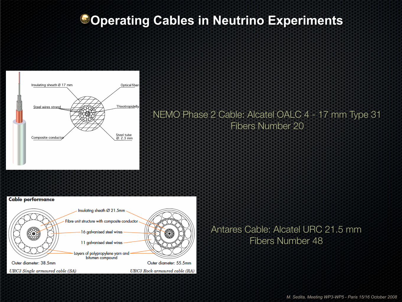
NEMO Phase 2 Cable: Alcatel OALC 4 - 17 mm Type 31Fibers Number 20
Antares Cable: Alcatel URC 21.5 mmFibers Number 48
Operating Cables in Neutrino Experiments
M. Sedita, Meeting WP3-WP5 - Paris 15/16 October 2008
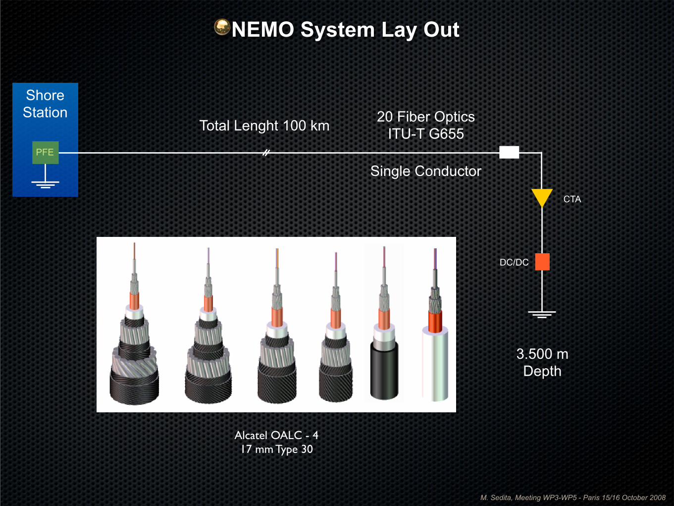
PFE
DC/DC
CTA
3.500 m Depth
Total Lenght 100 km 20 Fiber OpticsITU-T G655
Shore Station
Alcatel OALC - 417 mm Type 30
Single Conductor
NEMO System Lay Out
M. Sedita, Meeting WP3-WP5 - Paris 15/16 October 2008
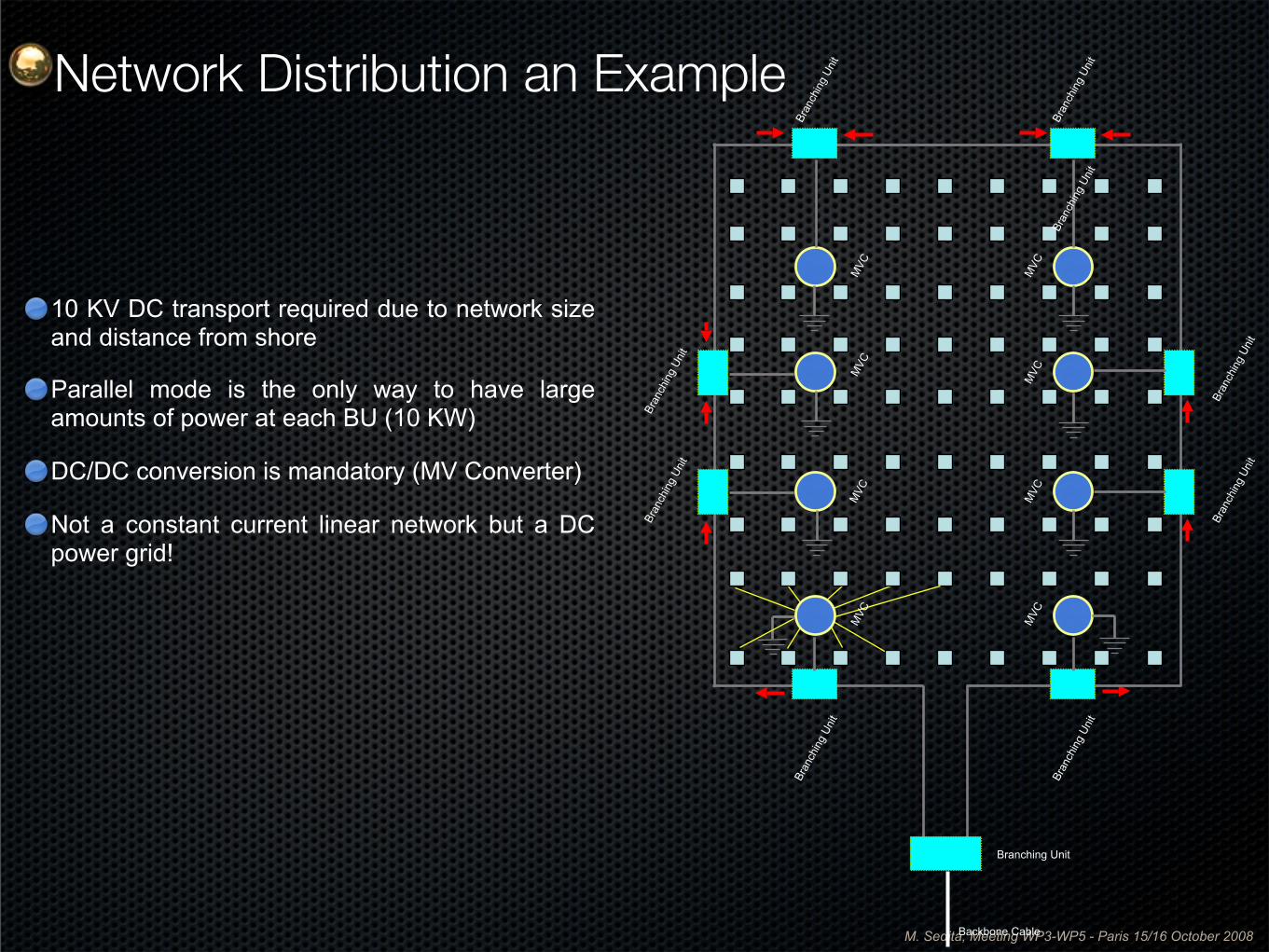
10 KV DC transport required due to network size and distance from shore
Parallel mode is the only way to have large amounts of power at each BU (10 KW)
DC/DC conversion is mandatory (MV Converter)
Not a constant current linear network but a DC power grid!
Bran
chin
g Un
it
MVC
Bran
chin
g Un
it
Bran
chin
g Un
it
Bran
chin
g Un
it
Bran
chin
g Un
it
Bran
chin
g Un
it
Bran
chin
g Un
it
Bran
chin
g Un
it
MVC
MVC
MVC
MVC
MVC
MVC
MVC
Branching Unit
Bran
chin
g Un
it
Backbone Cable
Network Distribution an Example
M. Sedita, Meeting WP3-WP5 - Paris 15/16 October 2008
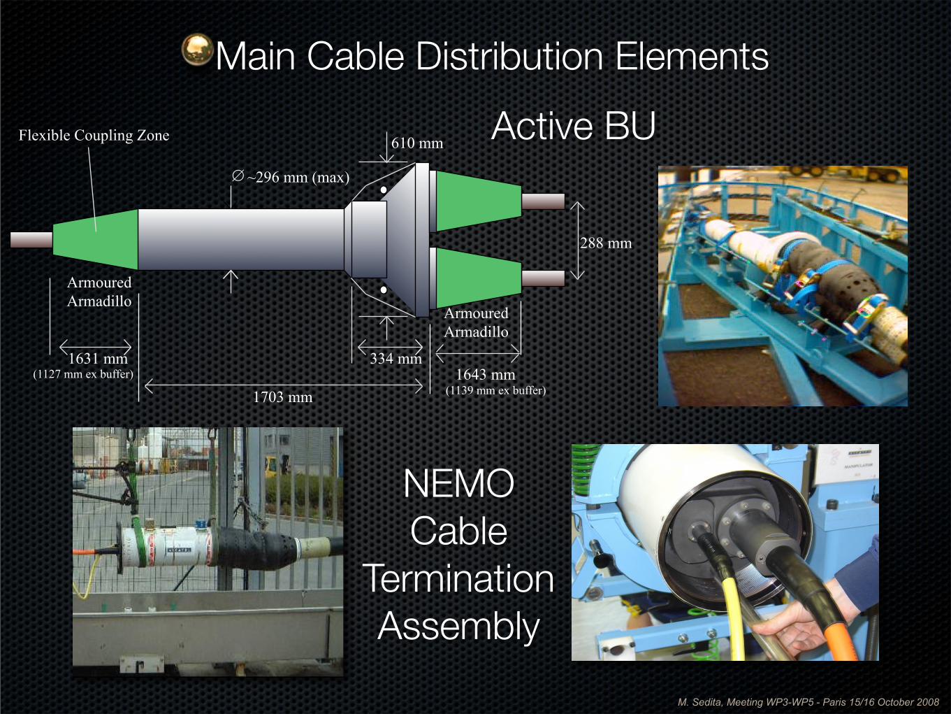
334 mm 1631 mm
288 mm
610 mm
~296 mm (max)
1703 mm 1643 mm
∅
Flexible Coupling Zone
(1139 mm ex buffer) (1127 mm ex buffer)
Armoured Armadillo
Armoured Armadillo
Active BU
NEMOCable
Termination Assembly
Main Cable Distribution Elements
M. Sedita, Meeting WP3-WP5 - Paris 15/16 October 2008
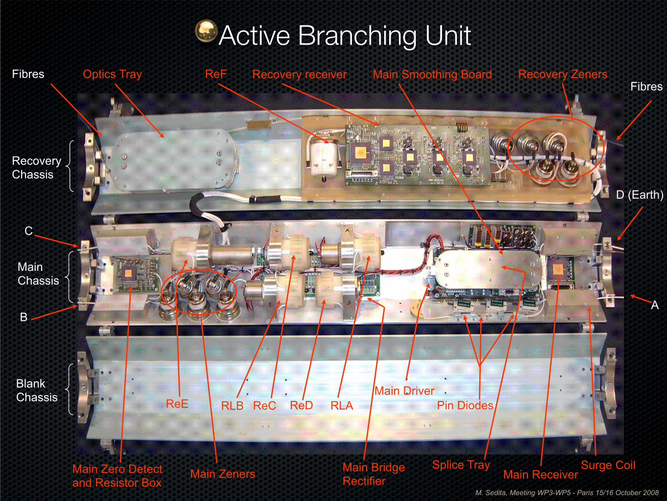
A
C
B
D (Earth)
FibresOptics Tray ReF Recovery receiver Recovery Zeners
Main ZenersSplice TrayMain Zero Detect
and Resistor BoxSurge CoilMain Bridge
Rectifier
ReE
Recovery Chassis
Main Chassis
Blank Chassis
Fibres
ReCRLB ReD RLA
Main Smoothing Board
Main Receiver
Main DriverPin Diodes
Active Branching Unit
M. Sedita, Meeting WP3-WP5 - Paris 15/16 October 2008
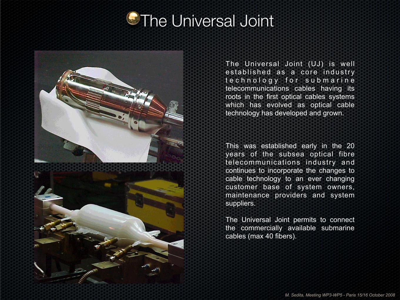
The Universal Joint (UJ) is well es tab l i shed as a co re i ndus t r y t e c h n o l o g y f o r s u b m a r i n e telecommunications cables having its roots in the first optical cables systems which has evolved as optical cable technology has developed and grown.
This was established early in the 20 years of the subsea optical fibre te lecommunicat ions industry and continues to incorporate the changes to cable technology to an ever changing customer base of system owners, maintenance providers and system suppliers.
The Universal Joint permits to connect the commercially available submarine cables (max 40 fibers).
The Universal Joint
M. Sedita, Meeting WP3-WP5 - Paris 15/16 October 2008
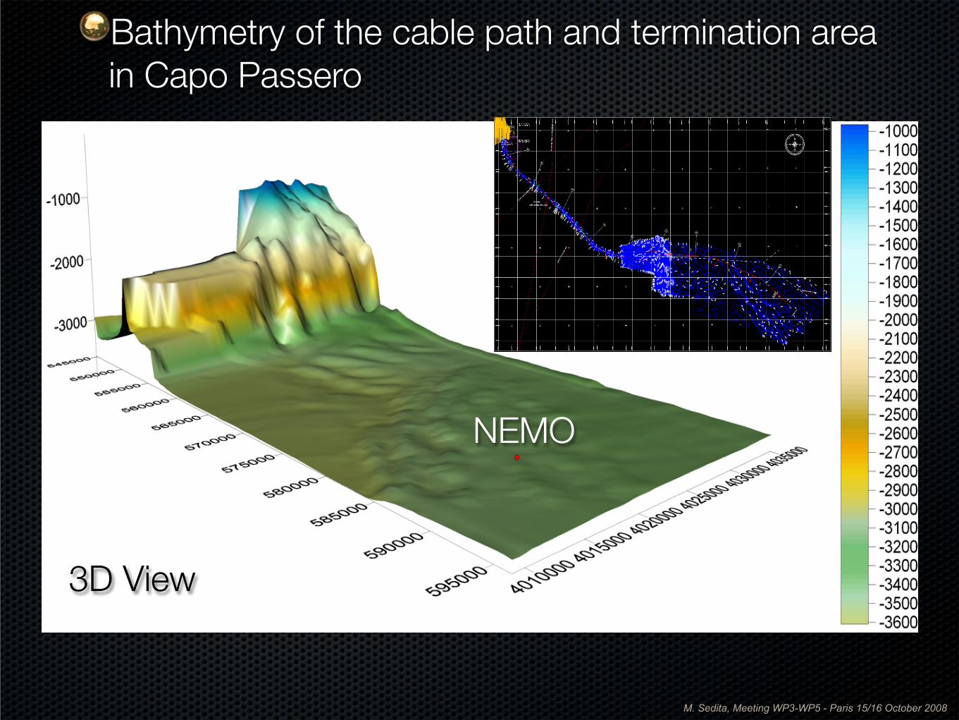
NEMO
3D View
Bathymetry of the cable path and termination area in Capo Passero
M. Sedita, Meeting WP3-WP5 - Paris 15/16 October 2008
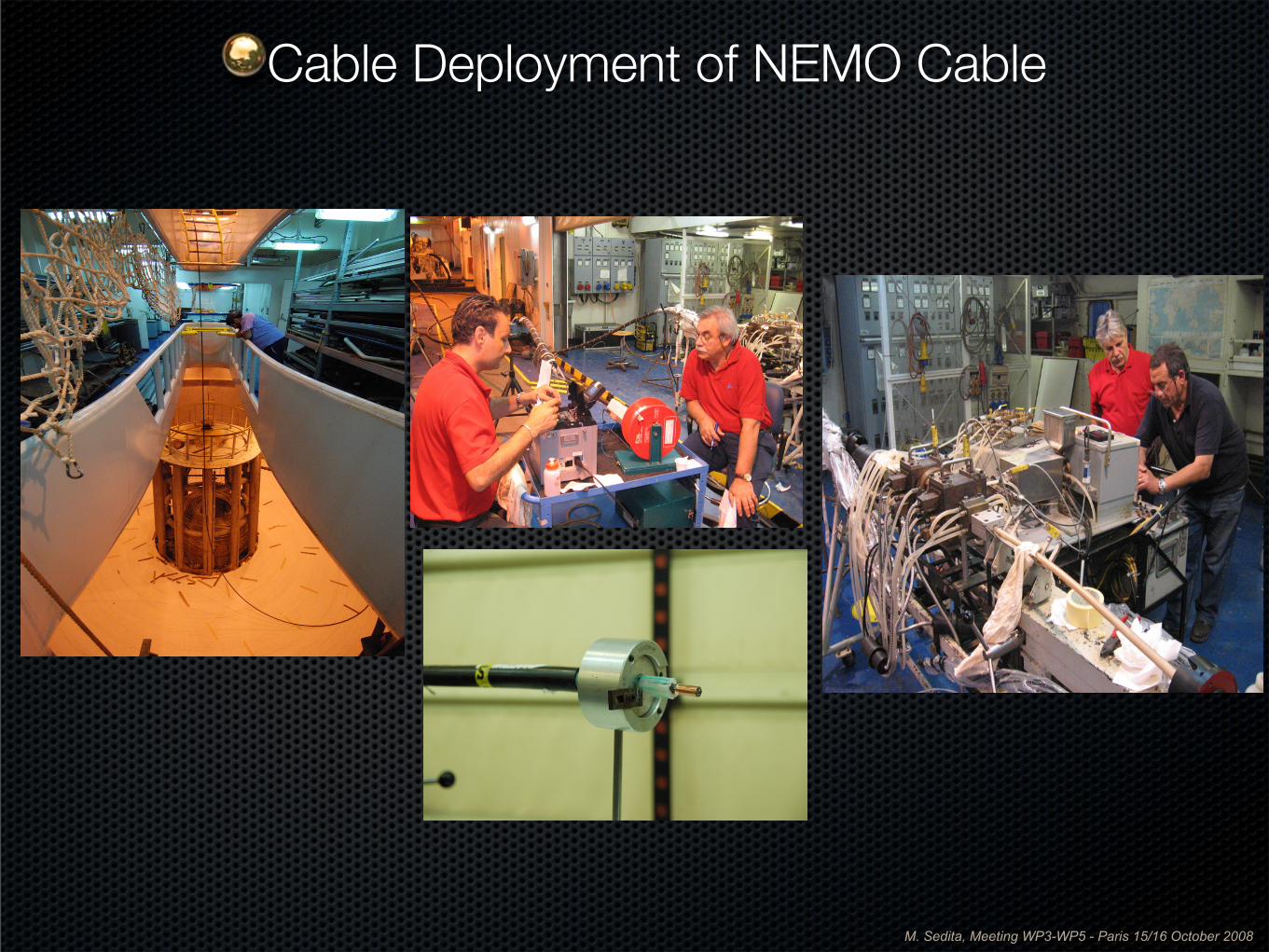
Cable Deployment of NEMO Cable
M. Sedita, Meeting WP3-WP5 - Paris 15/16 October 2008
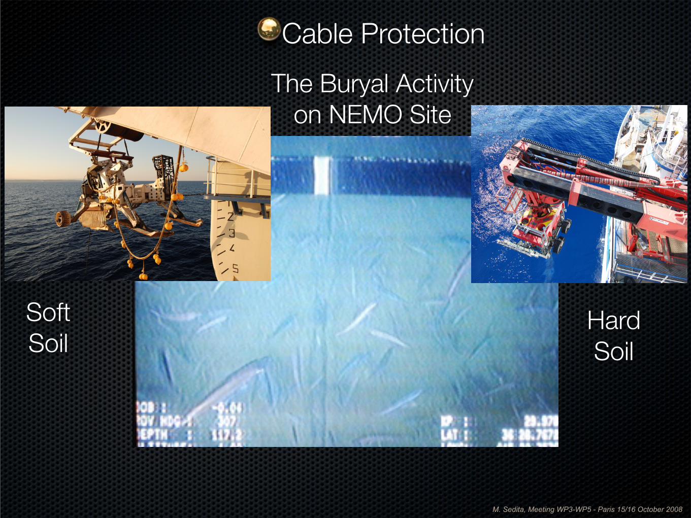
The Buryal Activity on NEMO Site
SoftSoil
HardSoil
Cable Protection
M. Sedita, Meeting WP3-WP5 - Paris 15/16 October 2008
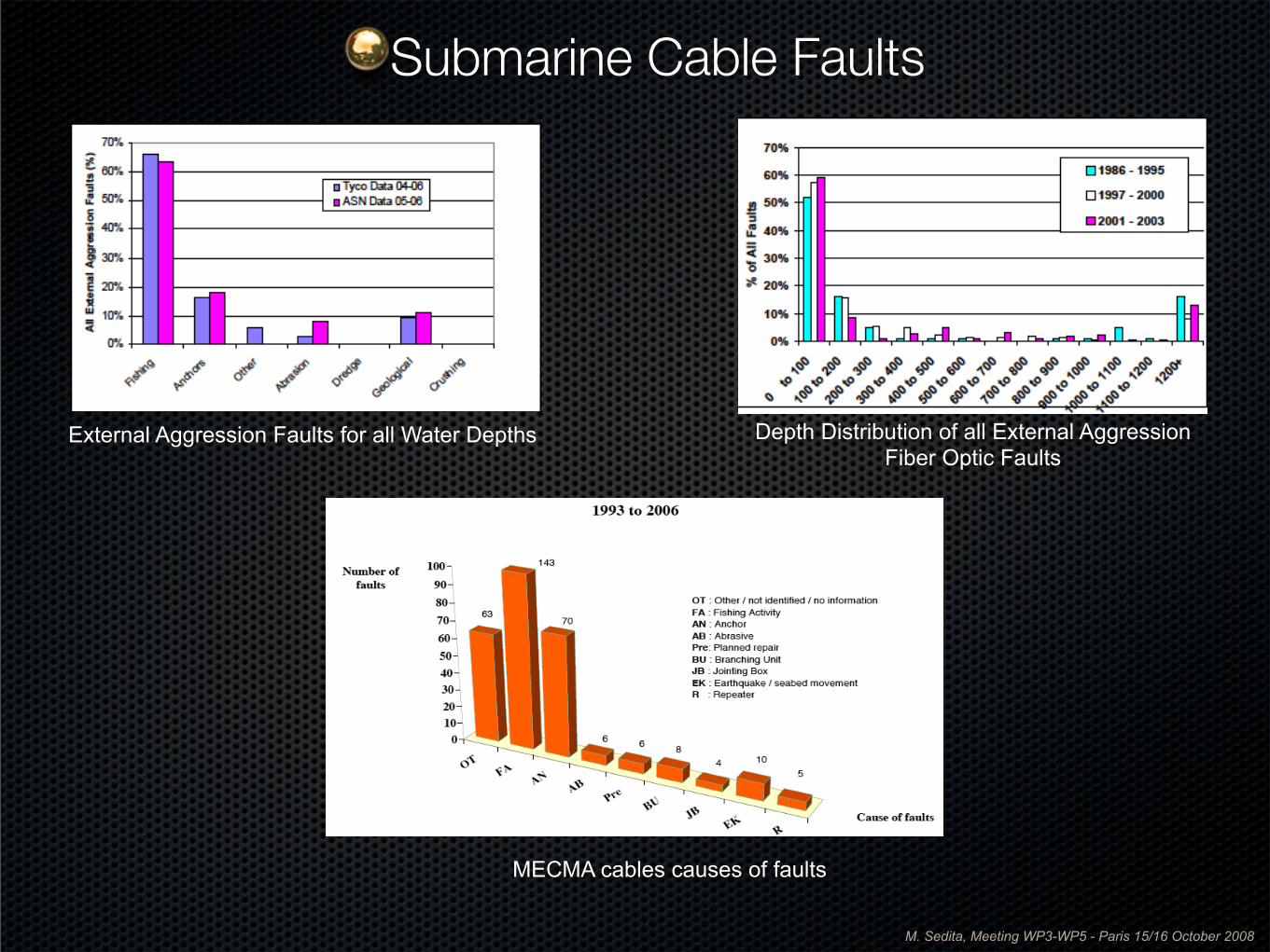
External Aggression Faults for all Water Depths Depth Distribution of all External AggressionFiber Optic Faults
MECMA cables causes of faults
Submarine Cable Faults
M. Sedita, Meeting WP3-WP5 - Paris 15/16 October 2008
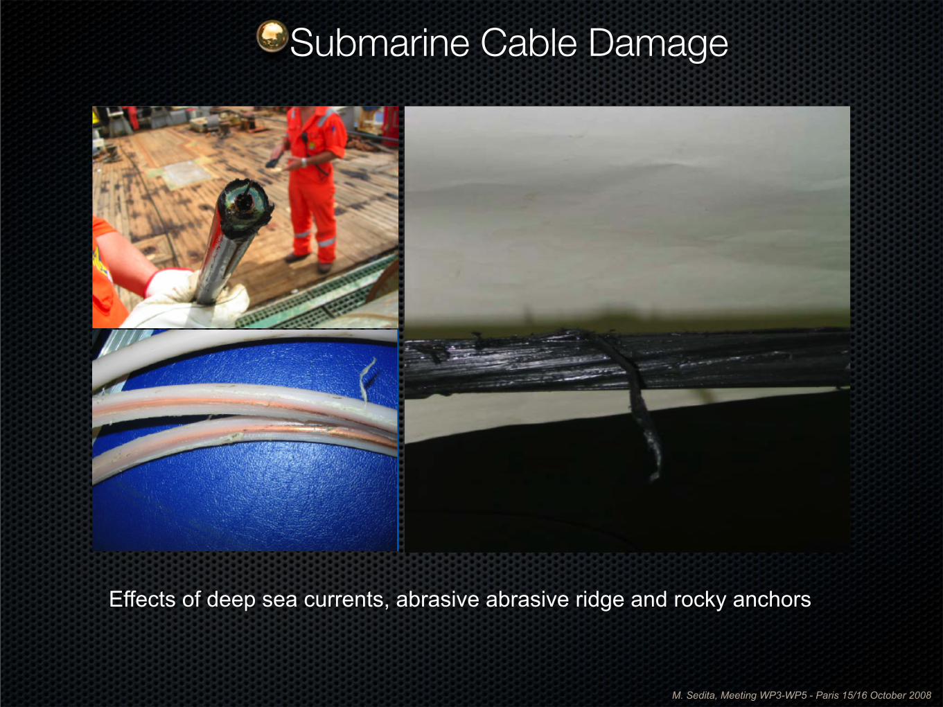
Effects of deep sea currents, abrasive abrasive ridge and rocky anchors
Submarine Cable Damage
M. Sedita, Meeting WP3-WP5 - Paris 15/16 October 2008
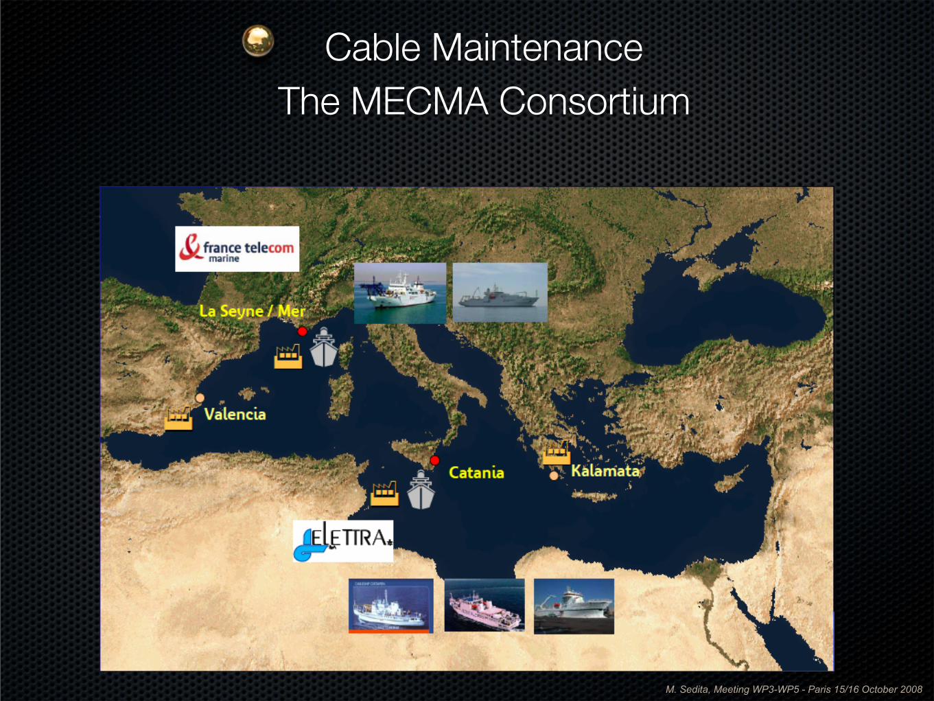
Cable Maintenance The MECMA Consortium
M. Sedita, Meeting WP3-WP5 - Paris 15/16 October 2008
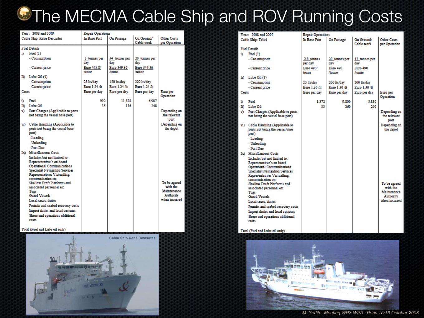
The MECMA Cable Ship and ROV Running Costs
M. Sedita, Meeting WP3-WP5 - Paris 15/16 October 2008
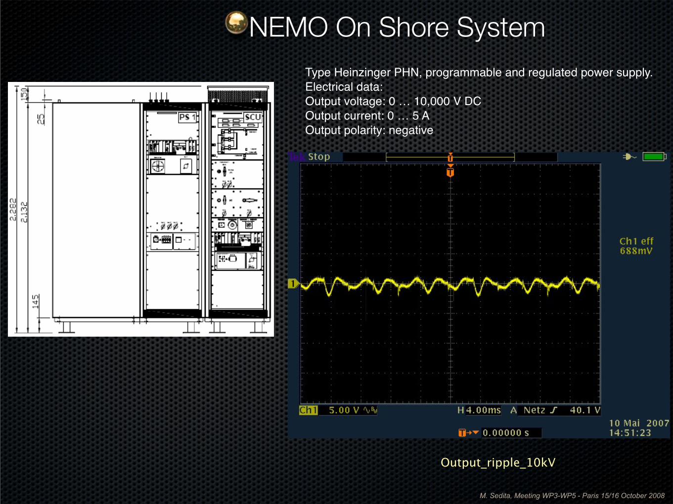
NEMO On Shore SystemType Heinzinger PHN, programmable and regulated power supply.Electrical data:Output voltage: 0 … 10,000 V DCOutput current: 0 … 5 AOutput polarity: negative
Output_ripple_10kV
M. Sedita, Meeting WP3-WP5 - Paris 15/16 October 2008
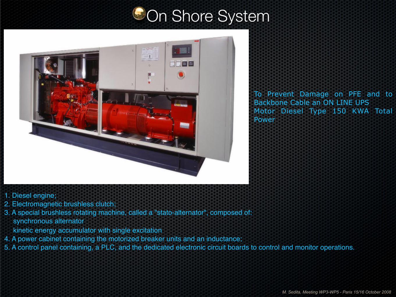
To Prevent Damage on PFE and to Backbone Cable an ON LINE UPS Motor Diesel Type 150 KWA Total Power
1. Diesel engine;2. Electromagnetic brushless clutch;3. A special brushless rotating machine, called a "stato-alternator", composed of: synchronous alternator kinetic energy accumulator with single excitation4. A power cabinet containing the motorized breaker units and an inductance;5. A control panel containing, a PLC, and the dedicated electronic circuit boards to control and monitor operations.
On Shore System
M. Sedita, Meeting WP3-WP5 - Paris 15/16 October 2008
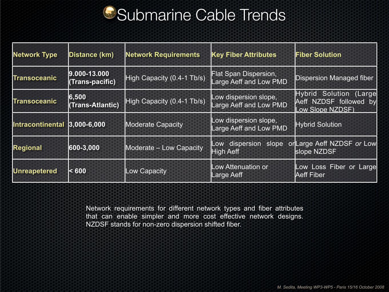
Network Type Distance (km) Network Requirements Key Fiber Attributes Fiber Solution
Transoceanic 9.000-13.000(Trans-pacific) High Capacity (0.4-1 Tb/s) Flat Span Dispersion,
Large Aeff and Low PMD Dispersion Managed fiber
Transoceanic 6,500(Trans-Atlantic) High Capacity (0.4-1 Tb/s) Low dispersion slope,
Large Aeff and Low PMD
Hybrid Solution (Large Aeff NZDSF followed by Low Slope NZDSF)
Intracontinental 3,000-6,000 Moderate Capacity Low dispersion slope,Large Aeff and Low PMD Hybrid Solution
Regional 600-3,000 Moderate – Low Capacity Low dispersion slope or High Aeff
Large Aeff NZDSF or Low slope NZDSF
Unreapetered < 600 Low Capacity Low Attenuation orLarge Aeff
Low Loss Fiber or Large Aeff Fiber
Network requirements for different network types and fiber attributes that can enable simpler and more cost effective network designs. NZDSF stands for non-zero dispersion shifted fiber.
Submarine Cable Trends
M. Sedita, Meeting WP3-WP5 - Paris 15/16 October 2008
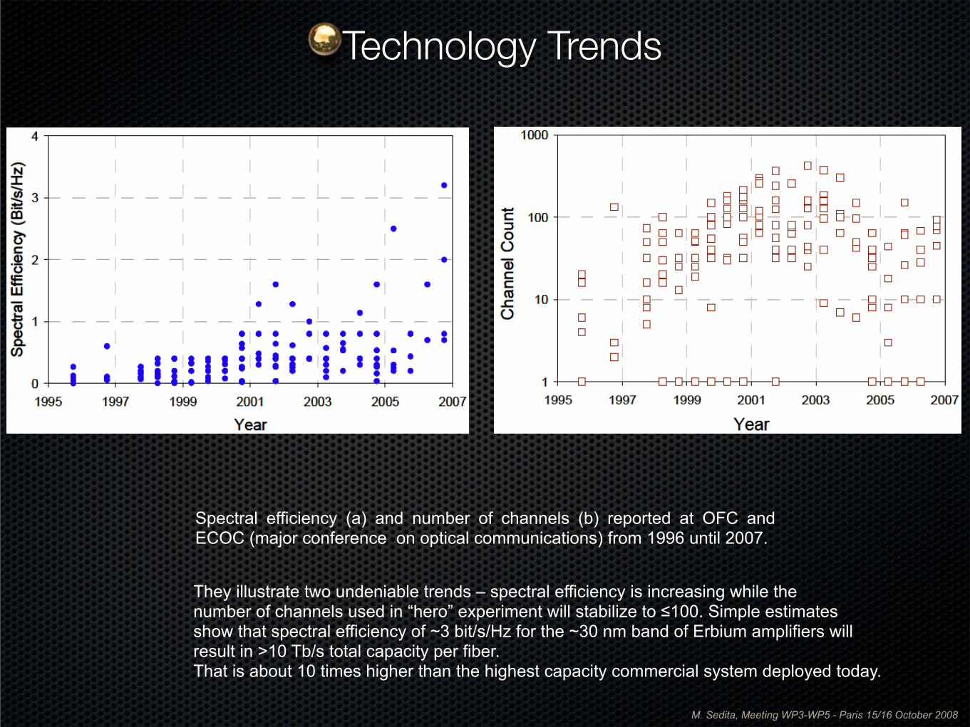
Spectral efficiency (a) and number of channels (b) reported at OFC and ECOC (major conference on optical communications) from 1996 until 2007.
They illustrate two undeniable trends – spectral efficiency is increasing while thenumber of channels used in “hero” experiment will stabilize to ≤100. Simple estimates show that spectral efficiency of ~3 bit/s/Hz for the ~30 nm band of Erbium amplifiers will result in >10 Tb/s total capacity per fiber.That is about 10 times higher than the highest capacity commercial system deployed today.
Technology Trends

M. Sedita, Meeting WP3-WP5 - Paris 15/16 October 2008
Thank You