REQUEST FOR PROPOSAL - shar.eprocure.isro.gov.in · SPM Special Purpose Machines SS Stainless Steel...
154
REQUEST FOR PROPOSAL FOR DETAILED ENGINEERING, FABRICATION, AUTOMATION (AS PER DRAWINGS & TECHNICAL SPECIFICATION DOCUMENT) and SUPPLY, ERECTION, TESTING & COMMISSIONING OF SPECIAL PURPOSE MACHINES 1. BLAST CLEANING MACHINE 2. DEGREASING MACHINE 3. RESIN LINING MACHINE Satish Dhawan Space Centre SHAR Indian Space Research Organization Sriharikota– 524124, Andhra Pradesh
Transcript of REQUEST FOR PROPOSAL - shar.eprocure.isro.gov.in · SPM Special Purpose Machines SS Stainless Steel...

REQUEST FOR PROPOSAL
FOR
DETAILED ENGINEERING, FABRICATION, AUTOMATION
(AS PER DRAWINGS & TECHNICAL SPECIFICATION DOCUMENT )
and SUPPLY, ERECTION, TESTING & COMMISSIONING
OF
SPECIAL PURPOSE MACHINES
1. BLAST CLEANING MACHINE
2. DEGREASING MACHINE
3. RESIN LINING MACHINE
Satish Dhawan Space Centre SHAR Indian Space Research Organization Sriharikota– 524124, Andhra Pradesh


Acronyms
CCTV Close Circuit Television
CISF Central Industrial Security Force
DAP Delivered at place
DDP Delivered Duty paid
ECS Electronic Clearance System
GA (drawing) General Arrangement (drawing)
HF High Frequency
HIL Hardware Insulation Lining Facility
IP Ingress Protection
ISRO Indian Space Research Organization
LC Letter of Credit
MCC Motor Control Centre
PLC Programmable Logic Control
RFP Request for Proposal
SDSC Satish Dhawan Space Centre
SPM Special Purpose Machines
SS Stainless Steel
UPS Uninterrupted Power Supply


1
PROPOSAL DOCUMENT
Proposals are invited from the interested Bidders for the enclosed scope of work as two part bid. Part-1 :Technical and Unpriced part of the work and Part-2 : Priced Commercial bid. The RFP document is organized in four sections as follows.
Section–A General Terms and Conditions of the Contract Section–B Scope of Work Section–C Technical Specifications Section–D Annexures
1. Title of the Entity: “ASMP Project (SPROB),SDSC SHAR / SRIHARIKOTA”
2. Title of Proposal: “PROPOSAL FOR DETAILED ENGINEERING, FABRICATION,
AUTOMATION, SUPPLY, ERECTION, TESTING & COMMISSIONING OF SPECIAL PURPOSE MACHINES of HIL-2 Facility”.
1 PROPOSAL DOCUMENT
Overall specifications and functional requirements are detailed in the proposal document. Bidder shall print, sign and stamp each page of proposal as token of acceptance & submit scan copy of the same along with the offer.
The proposal shall be completely filled in all respects and shall be submitted together with requisite information and Annexures. Any offer incomplete in any particulars is liable to be rejected.
If the space in the Proposal or any schedule or Annexures thereto is insufficient, pages shall be separately added.
The Proposal shall be opened on the date and at the time, specified in the Letter Inviting Bid. Proposal not received in time shall not be considered.
Bidder shall set their quotations in firm figures and without qualifications or variations or additions in the terms of the Proposal documents. Proposal containing qualifying expressions such as "subject to minimum acceptance” or "subject to prior sale" or any other qualifying expressions or incorporating terms and conditions at variance with the terms and conditions incorporated in the Proposal documents are liable to be rejected.

2
2 PREPARATION OF BIDS
2.1 SITE VISIT: The Bidder may visit SDSC SHAR and acquaint himself fully with the requirements and no claims whatsoever will be entertained on the plea of ignorance of difficulties in the execution of the work. Before submitting the tender, the Bidder shall be deemed to have clearly understood and satisfied himself regarding the work and services, all conditions liable to be encountered during the execution thereof and that prices quoted in the offer are adequate and all-inclusive with respect to all factors, circumstances and conditions likely to be incidental, both direct and indirect, to the work and services. If the bidder wishes to see the site, the bidder may do so within 15 days from the date of issue of tender enquiry.
2.2 VALIDITY OF OFFER: Bid shall remain valid for a period of 4 (four) months from the due date of submission of the Bid. The Bidder shall not be entitled during the said period to revoke or cancel his Bid or to vary the Bid except and to the extent required by Purchaser and communicated in writing. Bid shall be revalidated for extended period as required by Purchaser in writing. In such cases, unless otherwise specified, it is understood that validity is sought and provided without varying either the quoted price or any other terms and conditions of Bid finalized till that time.
2.3 COST OF BIDDING: All direct and indirect costs associated with the preparation and submission of Bid (including clarification meetings and site visit, if any), shall be to Bidder's account and the Purchaser will in no case be responsible or liable for those costs, regardless of the conduct or outcome of the Bid process.
2.4 APPLICABLE LANGUAGE: The Bid and all correspondence incidentals to and concerning the Bid shall be in the English Language. For supporting document and printing literature submitted in any other language, an accurate English Translation shall also be submitted.
2.5 ARRANGEMENT OF BID : The Bid shall be neatly presented and shall not contain any terms and conditions which are not applicable to the Bid. The Bid and all details submitted by the Bidder shall be signed and stamped on each page as token of acceptance by a person, legally authorized to enter into agreement on behalf of the Bidder. Corrections/ alteration, if any, shall also be signed by the same person. Bidder shall submit Power of Attorney in favour of the person who signs the Bid and subsequent submissions on behalf of the Bidder. Purchaser will not be bound by any Power of Attorney granted by the Bidder or changes in the constitution of the firm made subsequent to submission of the Bid or after the award of the contract. Bidder may however, recognize such Power of Attorney and changes after obtaining proper legal advice, the cost of which will be borne by the Bidder.

3
The cancellation of any document such as Power of Attorney, partnership Deed etc should be communicated by the Bidder to the Purchaser in writing well in time, failing which Purchaser shall have no responsibility or liability for any action taken by Bidder on the strength of the said documents. All the relevant papers shall be scanned and uploaded along with bid
2.6 SCHEDULE OF PRICES: The schedule of prices shall be read in conjunction with all the sections of proposal document. The prices quoted by the Bidder shall be firm and fixed till the completion of the work. The price shall be filled in the price format available in e-procurement portal only.
2.7 DOCUMENTS COMPRISING THE BID:
2.7.1 PART – I: TECHNICAL AND UNPRICED COMMERCIAL PART
Technical and un-priced commercial part comprising the following information shall be uploaded in e-procurement portal.
a. Scan copy of bid letter along with one set of proposal document duly signed and stamped on each page as a token of acceptance.
b. Scan Copy of Company’s registration number certificate.
c. Scan copy of Power of attorney in favour of authorized signatory of the bid / proposal documents.
d. All the annexures of the bid shall be duly filled and signed.
e. Scan copy of Un-priced copy of schedule of prices (Annexure-VI) with all other commercial terms and conditions duly filled (Instead of price figures, bidder shall write “QUOTED”) signed.
f. Data sheets for all the equipment & sub-systems
g. Technical details, equipment general arrangement drawings, catalogues etc., as applicable and any other drawing, document as mentioned in the proposal.
h. Audited balance sheet including profit and loss account for the last three financial years showing annual turnover.
i. Latest income tax clearance certificate.
j. Latest solvency certificate for an amount of Rs. 65 lakhs from a scheduled bank.
k. List of projects in hand & completed indicating the name of the client, contact person, contract value, nature of work, work completed, work balance, name of Consultant, month & year of commencement & completion etc.
l. Organization chart for the proposed work with bio data of key personnel
m. Schedule Bar charts for realization of SPECIAL PURPOSE machines.
n. Execution Plan. Any part of the work is planned to outsource, details of the same shall be provided along with bid documents.
o. Any other relevant document, Bidder desires to submit.

4
2.7.2 PART – II: PRICE BID
Priced commercial bid shall contain schedule of prices, percentage of sales/ service taxes and shall be filled in ISRO e-procurement portal only. No deviations to terms and conditions, assumptions, discounts etc. shall be stipulated in price bid. Purchaser will not take cognizance of any such statement and may at their discretion reject such bids.
2.8 BID SUBMISSION :
2.8.1 BID SHALL BE SUBMITTED IN TWO PARTS
Part 1: Techno-commercial part of the bid
Part 2: Priced part of the bid
2.8.2 Offer should be submitted online using standard digital signature of class -3 with encryption/decryption options.
2.8.3 The tenders authorized online on or before the open authorization date and time will only be considered as valid tenders.
2.8.4 Prices shall be mentioned in the space/column provided in the ISRO e-procurement portal only.
2.8.5 Prices shall not be uploaded along with technical specifications in any form. If so, such bids will not be considered.
2.8.6 Un-Priced format (Annexure- VI) shall be filled saying “QUOTED” and shall be submitted along with the technical bid. This is only to ensure that the bidder has provided all the details
2.8.7 Prices quoted should be on the basis of DAP or DDP (SDSC SHAR, Sriharikota).
2.8.8 The Purchaser will not pay separately for transit insurance and same shall be included in the cost quoted by the Bidder.
2.8.9 All risks in transit shall be exclusively borne the contractor and the Purchaser shall pay only for such items that are actually received in good condition in accordance with the purchase order.
2.8.10 Bids duly filled in by the Bidder should be submitted as stipulated in the e-procurement portal.
2.8.11 Purchaser will open Part – I of the bid on the due date of opening. Price Bid (Part-II) of the bids which are technically and commercially acceptable shall be opened at a later date with prior intimation to all qualified bidders.
2.8.12 Purchaser reserves the right to reject any or all the Bids without assigning any reasons thereof.
2.9 BID EVALUATION :
2.9.1 Bids submitted by the bidders who meet pre-qualification criteria (Annexure-V) only will be considered.

5
2.9.2 The bidder shall provide all the relevant data/information/details required for evaluating the bid technical and commercially in the specific formats enclosed with the tender. Apart from this, Bidder is free to add any other relevant information.
2.9.3 During evaluation, Purchaser may request Bidder for any clarification on the bid/ additional documents/ information required. Bidder shall submit all clarifications/ additional documents/ information requested in original. If not submitted within the stipulated time Purchaser has right to reject such bids.
2.9.4 The complete scope of work is defined in the Proposal document. Only those Bidders who undertake total responsibility for the complete scope of work as defined in the Proposal document only will be considered. In case of part supply, the bid will no0t be considered.
2.9.5 In case bid does not fully comply with the requirement of Proposal document and the bidder stipulates deviations to the clauses of the proposal, which are unacceptable to the Purchaser, the Bid will be rejected.
2.9.6 Performance of Bidder on similar nature of works executed/ under execution shall be taken into consideration
2.9.7 Purchaser reserves right to visit client’s site for verification/ validation.
2.9.8 The time schedule for completion is given in the Proposal document. Bidder is required to confirm the completion period unconditionally. Purchaser reserves the right to reject bids which does not comply with the delivery schedule.
2.9.9 Purchaser shall not be obliged to furnish any information/ clarification to unsuccessful bidder as regard to non-acceptance of their Bids.
2.9.10 Overall lowest offer for all the machines (including spares given in Annexure-II), will be considered for award of Purchase Order.
3 DETERMINATION OF RESPONSIVENESS
SDSC SHAR will scrutinize the bids to determine whether the bid is substantially responsive to the requirements of the tender document. For the purpose of this clause, a substantially responsive bid is one which inter-alia conforms to all the terms and conditions of the entire Tender document without any deviations and reservations. The decision of Purchaser shall be final in this regard.

6
SECTION –A
GENERAL TERMS AND CONDITIONS OF
CONTRACT

7
1 INTRODUCTION
SDSC SHAR invites tenders from reputed firms with proven ability in “ DETAILED ENGINEERING, FABRICATION, AUTOMATION, SUPPLY, ERECTION, TESTING and COMMISSIONING OF SPECIAL PURPOSE MACHINES” for SDSC SHAR, Sriharikota as per the scope and specifications.
1.1 Nomenclature applicable in this report: M/s Satish Dhawan Space Centre SHAR (SDSC SHAR), ISRO / Dept. of Space (DOS), Govt. of India hence forth called as a “Purchaser”. Any person or firm or group of firms who are participating in this bid hence forth called as “Bidder”.
2 SCHEDULE OF PRICE
2.1 CONTRACT price shall include all costs of “ DETAILED ENGINEERING, FABRICATION, AUTOMATION, SUPPLY, ERECTION, TESTING and COMMISSIONING OF SPECIAL PURPOSE MACHINES”, Shop floor testing, packing, forwarding, transport to site, unloading, storage, all risk coverage, erection, installation, training, testing & evaluation and commissioning of equipment including associated civil work and any other cost for proper and complete execution of the CONTRACT.
2.2 CONTRACT prices shall also include all travelling expenses, living expenses, salaries, overtime, benefit and any other compensation for engineers, supervisors, skilled, semiskilled workmen, watch and ward staff, laborer and other staff employed by the Bidder, cost of tools and tackles required for erection and other consumable material required, and all taxes, duties, and levies as applicable on the date of submission of bid.
2.3 Price quoted shall be firm & fixed. The price shall be filled in the format available in e-procurement portal. The bidder shall also fill up the format enclosed (Annexure VI) without price figures and shall confirm by filling the appropriate fields as “QUOTED”.
2.4 The rate quoted shall be on the basis of DAP or DDP (SDSC SHAR, Sriharikota). 2.5 All rates of taxes/duties/levies applicable with details of percentage and applicable portion
of the price should be spelt out clearly in the offer. 2.6 The taxes applicable for supply, erection & commissioning shall be indicated separately in
terms of percentage in the price bid. If the offers submitted by the bidders are silent on taxes, it will be presumed that quoted rates are inclusive of taxes & duties and no claim in this regard will be entertained later.
2.7 The variation in the GST or applicable statutory taxes shall be paid on documentary evidence submitted by the bidder during this contract.
3 MODE OF PAYMENT
All the payments due to Bidder shall be made through RTGS/ NEFT. Bidder shall submit the banker details and payments can also be made through Electronic Clearance System (ECS).

8
4 TERMS OF PAYMENTS
4.1 Our standard payment term is 80% of supply cost including taxes and transportation cost within 30 days after receipt and acceptance of sub-systems at SDSC SHAR. 20% of supply portion and 100 % of erection and commissioning charges along with taxes will be paid after successful commissioning and handing over of the machine at SDSC SHAR on submission of Performance Bank Guarantee.
4.2 Wherever advance payment is requested, Bank Guarantee from any Nationalized Bank/Scheduled Bank should be furnished. In case of advance payments, if the bidder is not supplying the material within the delivery schedule, interest will be levied as per the Bank Lending Rate plus 2% penal interest.
4.3 Interest will be loaded for advance payments/stage payments as per the lending rate of Bank and will be added to the landed cost for comparison purpose. In case of different milestone payments submitted by the parties, a standard and transparent methodology of NPV (Net present value) will be adopted for evaluating the offers.
5 DELIVERY SCHEDULE
5.1 Bidder shall follow the following schedule for executing the contract
S. No Mile Stone Expected date of
completion
1 Purchase order date T
2 Submission of DETAILED ENGINEERING and
FABRICATION drawings
T + 2 weeks
3 Date of clearance of DETAILED ENGINEERING and
FABRICATION drawings
T + 4 Weeks
4 Submission of final drawings for Fabrication T + 6 weeks
5 Readiness of Machines for pre delivery inspection
at Bidder’s site
T + 34 weeks
7 Delivery of Machines at purchaser’s site T + 36 weeks
8 Installation, Testing & Commissioning T + 46 weeks
NOTE: Micro schedule shall be submitted by the bidder after placement of order
5.2 The Bidder shall inform the Purchaser within 30 days of any occurrence that is likely to cause delay in delivery. The Purchaser shall determine, in the light of circumstances reported, whether or not any respite or modification of the delivery requirements of the contract can be permitted on this account.
5.3 An extension of the time limit for execution or postponement of delivery shall be granted only in the respect of delay, which is not attributable to the fault or the negligence of the Bidder.

9
An extension of the time limit for execution shall be granted to the bidder to the extent that he establishes force majeure events.
6 LIQUIDATED DAMAGES
In the event of the Bidder failing to complete the work within the delivery period specified in the contract agreement or any extension agreed thereto, the Purchaser shall reserve the right to recover from the Bidder as liquidated damages, a sum of 0.5 percentage per week or part thereof of the undelivered portion of the total contract price of equipment or work. The Total liquidated damages shall not exceed the 10.0 percentage of the total Contract price.
7 TAXES AND DUTIES
7.1 GST: The bidder shall clearly indicate the percentage of GST applicable.
7.2 INCOME TAX: Income tax at the prevailing rate as applicable and if applicable from time to time shall be deducted from the bidder’s bills as per Income Tax Act and a certificate will be issued (TDS Certificate).
7.3 EARNEST MONEY DEPOSIT (EMD)
7.4 The Earnest Money Deposit (EMD) as Bank Guarantee for Rs 5,00,000/- (Rupees five Lakh Only), refundable (without interest), should be necessarily accompanied with the technical Bid in the form of Demand Draft drawn in favour of Accounts Officer, SDSC SHAR, Sriharikota failing which the tender shall be rejected summarily. However, the bidders coming under the GOI EMD exemption list, shall be exempted from EMD on submission of documentary evidence.
8 RISK COVERAGE
The Bidder shall arrange comprehensive risk coverage at his own cost covering the value of equipment including transportation to the site from manufacturer’s works, storage at site, fabrication, erection, testing and commissioning at site. The period of such coverage shall be up to contractual completion period or any extension granted by Purchaser thereof.
9 SECURITY DEPOSIT
9.1 The bidder whose tender is accepted will be required to furnish by way of Security Deposit for the due fulfillment of the contract such a sum as will amount to 10 % of the contract price of the work awarded in the form of Bank Guarantee valid till the satisfactory execution of the contract and acceptance.
9.2 The security deposit (bearing no interest) shall be held by the Purchaser as security till satisfactory completion, testing and handing over of all the system and for the due performance of all bidders’ obligations under the contract as per delivery period or extension granted thereof by the Purchaser.
9.3 Within 10 days from the date of receipt of purchase order/ LOI, bidder shall deposit the security deposit to the Accounts officer, Satish Dhawan Space Centre SHAR, Sriharikota as detailed above by any of the following modes.

10
a) By a crossed demand draft in favor of Accounts officer, Satish Dhawan Space Centre SHAR drawn on SBI and payable at Sriharikota.
b) By submission of bank guarantee: The bank guarantee shall be from a reputed international/nationalized/schedule bank (in the prescribed format of our Dept).
9.4 In case of breach of contract, the Security deposit shall stand forfeited in addition to other relief available to the Purchaser under this contract.
10 PERFORMANCE BANK GUARANTEE
The bidder shall guarantee for the performance of the contract by providing bank guarantee in favour of the Purchaser for an amount equivalent to 10 % (ten percent) of the total value of this contract valid till the warranty period of the contract and additionally with a claim period of 60 days. The performance bank guarantee shall be submitted by the bidder with in fifteen days from the date of accepting the equipment by the Purchaser as per the CONTRACT. The format for the performance bank guarantee shall be obtained from Purchaser.
11 PACKING AND FORWARDING
The Bidder shall arrange to have all the material suitably packed as per the standards & statutes and as specified in the contract. Unless otherwise provided for in the contract, all containers (including packing cases, boxes, tins, drums, and wrappings) used by the Bidder shall be non-returnable.
All packing and transport charges, transit handling costs, transit risk coverage and transport fees of agents employed at the place of delivery or elsewhere, shall be deemed included in the price to be paid to the Bidder.
12 WARRANTY
The bidder shall provide minimum twelve months’ warranty for the entire system for a defect liability, after final official handing over at his cost. During this period bidder has to provide and adhere to the following:
12.1 This period shall include maintenance, replacement of defective/ failed parts at free of cost.
12.2 Bidder has to attend unlimited breakdown calls.
12.3 Purchaser will not provide any transport/accommodation for this purpose.
12.4 Upon oral or written notification of defects in or malfunctioning of the goods during the warranty period which require corrective action, bidder shall send the necessary personnel to job site to supervise and assume responsibility for repairs and/or replacement, if necessary, of the defective goods or material at his own cost. If Bidder does not respond, within seven (7) days after receipt of notification, the Purchaser has got every right to resolve reported problem and Purchaser may do so at the cost and expense of the Bidder. Bidder shall
11
reimburse to the Purchaser all expenses incurred by Purchaser to repair or replace malfunctioning or non-conforming goods and Forfeit the performance security.
12.5 Purchaser has no obligation to discover defects, patent or otherwise, and this shall be sole responsibility of Bidder. Inspection and clearance for shipment by Purchaser’s inspectors or Inspection agency appointed by Purchaser shall not relieve Bidder of any of his obligation and duties under the terms and conditions herein.
12.6 Where defects in items are remedied under warranty, the period for which the warranty operates shall be extended by such period, as the items were not available to the Purchaser. Where defects items are replaced by new ones, the full warranty period stipulated in the contract shall apply to such replacement items as from the date of their delivery.
12.7 Bidder shall obtain similar warrantee from each of his sub-bidders. However, the overall responsibility shall lie with the Bidder.
13 GUARANTEE
The Bidder shall guarantee that the equipment furnished by him are in conformance with the requirement of the specifications.
Goods covered by the contract shall be free from defects in design, materials or workmanship for a period of twelve months from the date of successful commissioning & acceptance by Purchaser.
14 DISCLOSURE AND USE OF INFORMATION BY THE BIDDER
14.1 If the documents supplied by the Purchaser are marked ‘restricted use’ the Bidder shall take all necessary steps to ensure that the requirements of the contract or any specification, plan, drawing, pattern, sample or information supplied by, or on behalf of, the Purchaser in connection therewith shall not be disclosed to any person other than a person employed or engaged by the Bidder, whether under sub-contract or otherwise, for the performance of the contract.
14.2 Bidder shall guarantee that all information and data received during execution of Contract from Purchaser shall be classified as confidential within the meaning of the Official Secrets Act and will not be divulged to any third bidder without prior written permission of Purchaser. All drawings & documents shall be returned after execution of work.
15 ARBITRATION
In the event of any question, dispute or difference arising under these conditions the purchase order or in connection with this contract, (except as to any matters the decision of which is specially provided for by these conditions) the same shall be referred to the sole arbitration of the Head of the Centre or of some other person appointed by him. The arbitration shall be conducted within India as per Arbitration & Conciliation Act 1996 and the applicable language shall be English. The arbitrator may be a Retired Judge or a Government Servant

12
or any other responsible person appointed by the head of the Purchaser. The award of the Arbitrator shall be final and binding on the parties of this contract.
16 IPR
Any IPR related issues arising out of infringement by the vendor shall be totally to his account and SDSC SHAR shall not be held responsible in any manner.
17 APPLICABLE LAW AND JURISDICTION
The contracts shall be interpreted in accordance with the laws of the Union of India. Any legal issue or dispute arising out of the contract are within the jurisdiction of Courts of Andhra Pradesh, India only.
18 FORCE MAJEURE
18.1 Force Majeure is an event beyond the control of the bidder and not involving the bidder’s fault or negligence and which is not foreseeable. Such events may include, but are not restricted to, acts of the purchaser either in its sovereign or contractual capacity, wars or revolutions, hostility, acts of public enemy, civil commotion, sabotage, fires, floods, explosions, epidemics, quarantine restrictions, strikes, lockouts, and freight embargoes.
18.2 If there is delay in performance or other failures by the bidder to perform its obligation under its contract due to event of a Force Majeure, if a Force Majeure situation arises, the bidder shall promptly notify the purchaser in writing of such conditions and the cause thereof within twenty-one (21) days of occurrence of such event.
18.3 Unless otherwise directed by the purchaser in writing, the bidder shall continue to perform its obligations under the contract as far as reasonably practical, and shall seek all reasonable alternative means for performance not prevented by the Force Majeure event.
18.4 There may be a Force Majeure situation affecting the purchase organization only. In such a situation the purchase organization is to take up with the bidder on similar lines as above for further necessary action.
19 EXTENSION OF WORK COMPLETION PERIOD
19.1 If the completion of deliveries of equipment or site work is delayed due to reason of Force Majeure the Bidder shall without delay give notice to the Purchaser in writing of their claim for an extension of time. The Purchaser on receipt of such notice may agree to extend the Contract period or delivery date as may be reasonable but without prejudice to other terms and conditions of the Contract.
19.2 Both parties shall keep a record of the circumstances referred to above which are responsible for causing delays in the execution of the services and shall give notice to the other bidder of any such cause as soon as it occurs. An event of Force Majeure, where so ever it occurs, provided it affects either bidder in fulfilling its obligations under this contract, shall justify the affected bidder’s claim of Force Majeure. Should one or both the parties be prevented from fulfilling their contractual obligations by a state of Force Majeure lasting continuously

13
for more than a month, the parties shall consult with each other regarding the future execution of the contract.
20 GENERAL SITE DETAIL
20.1 The SPECIAL PURPOSE MACHINES are to be erected inside the facility in SPROB, SDSC SHAR, Sriharikota, the place” Sriharikota” is 20 km East of Sullurupeta (nearest town) which is 80 km North of Chennai, Tamilnadu, INDIA.
20.2 SDSC SHAR, Sriharikota is a prohibited place. Hence, no contractor working personnel will be allowed to stay and they have to be accommodated in Sullurupeta town with his own arrangements.
20.3 The contractor may have to transport working personnel on day to day basis by his own arrangement. Location of the site is worked out to be 30 km away from Sullurupeta. The contractor personnel have to undergo security checks at entry gates by security force i.e. CISF of SHAR.
20.4 All the working personnel shall comply with code of conduct during their stay inside the SHAR campus.
21 SAFETY
Bidder shall follow the safety regulations / codes or safety instructions issued by PURCHASER and shall take necessary measures to meet these, at his own cost.
22 POWER SUPPLY
Electrical power provided by the Purchaser during installation of SPECIAL PURPOSE machine is NOT chargeable. Reasonable quality of normal power will be made available at one point (415V, 3 phase, 50 Hz). However, onward distribution shall be done by the bidder. All electrical installation by the bidder shall be as per safety regulation & standard and will be subjected to Purchaser inspection & approval.
23 WORK RULES
Generally, NO work shall be carried out during night or public holidays unless a written permission is obtained from Purchaser.
24 SITE CLEARANCE
Upon completion of work, Bidder shall remove all his equipment and material from the site within one month or time mutually agreed. Bidder at all times shall keep site in clean condition and remove all unwanted material at regular intervals. In case bidder fails to remove all his equipment and material within the mutually agreed time it is deemed that Purchaser will arrange to remove the same at the bidder’s cost besides imposing penalty for failure.

14
25 ACCOMMODATION
Very limited accommodation may be provided by Purchaser to senior supervisory staff of the Bidder on chargeable basis subject to availability.
Bidder shall make his own arrangement for accommodation & canteen facility for all its staff, technicians, labour & workers. Transportation shall be arranged by Bidder at his own expenses for his entire staff till the completion of the project.
26 MEDICAL FACILITIES
No medical facilities will be provided by Purchaser at site for Bidder’s personnel working at our site. Bidder shall make his own arrangement at his own expenses for medical facilities for site personnel.
27 PROJECT EXECUTION AND MONITORING
Upon placement of purchase order, bidder shall prepare a detailed programme schedule for review/approval by Purchaser. Bidder shall identify a project team with one senior official as a project leader. Bidder shall submit the project status report every 15 days giving the status of various activities w.r.t. planned schedule for realization of SPECIAL PURPOSE Machine. Bidder shall depute their Project team/ engineers for monthly meeting to review the status and discuss/ resolve minor issues related to project execution at SDSC SHAR/ bidder’s site based on mutual agreement on mutually agreeable dates.
28 SUB-CONTRACTS & OTHER TERMS
28.1 Whole of the work shall not be subcontracted.
28.2 The portion of the work for which the bidder is not expert, shall be sub-contracted to proven / reputed OEM in that field. Such sub- contract, if any, shall be given only after obtaining prior approval of the Purchaser. Details of works planned to sub-contract shall be provided in the bid.
28.3 The bidder shall be wholly responsible for the proper execution of any sub-contract placed by him in connection with this contract.
28.4 The conditions of the sub-contracts if any, shall be framed by the bidder such that interest of the Purchaser and its rights are protected in accordance with the original contract terms and conditions.
28.5 Written permission, if given, shall not relieve Bidder from his obligations under the Contract and bidder shall take full responsibility for all work done by Sub-Contractors. Bidder shall be responsible for transmitting pertinent data of all Contract terms and conditions to Sub-Bidders. Bidder shall furnish to Purchaser, copies of all un-priced sub-orders showing promised delivery dates and places.

15
28.6 Bidder shall employ an authorized & reputed system integrator of OEM of PLC Bidder, in case of outsourcing DACS works.
28.7 The system integrator shall provide the proof of authorization by OEM
28.8 The system integrator shall provide the proof of similar works carried out in last 3 years
28.9 Bidder shall obtain approval for the designs and drawings from the Purchaser before initiating the action for procurement / fabrication.
28.10 Bidder shall strictly adhere to the make/model given in the preferred bidder list under Annexure I.
28.11 Should there be any ambiguity or doubt as to the meaning of any of the tender clause/condition or if any further information is required, the matter shall be immediately brought to the notice of Head, Purchase & Stores, SDSC SHAR in writing for necessary clarifications prior to the opening of the tenders.
29 CHANGES & MODIFICATION to SPECIFICATIONS, DESIGNS, DRAWINGS and QUALITATIVE/ QUANTITATIVE REQUIREMENTS
29.1 Bidder shall obtain approval for the designs and drawings from the Purchaser before initiating the action for procurement / fabrication.
29.2 Change in make/model for bought item is NOT allowed unless approved by purchaser.
29.3 Purchaser is free to modify the designs or drawings during design review. Bidder has to carry out one time modifications at each stage without any extra cost and must obtain the approval from Purchaser during Detailed Engineering design review to meet overall specification of the machine & sub systems.
29.4 The Purchaser reserves the right at any time to modify the Quantitative Requirement, Specifications, patterns or drawings relating to the work covered by the contract. The Bidder shall inform the Purchaser, within 15 days, of any objection/reservation to the modifications required.
29.5 Unless the Purchaser directs otherwise, the Bidder shall in either case, submit within a reasonable time limit to be specified by the Purchaser, an estimate of the effect of any such modification in the cost of performance of the contract and/ or on the delivery schedule.
29.6 Any amendment to the contract, which may be necessary in this respect, will be established within a reasonable time in the form of an Amendment to Contract to be signed by both parties.
30 TRAINING
30.1 INSTRUMENTATION AND CONTROL SYSTEMS: Training should be provided from the Original Equipment Manufacturer or OEM Approved Training Centre at their training center or at our site for 2 persons deputed by Department on the following topics
a) Hot Standby PLC configuration and programming

16
b) Interfacing of drives, iMCCs and encoders with PLC
c) SCADA configuration, programming, trend and alarm generation and data backup.
The training shall be for a duration of 5 days covering all the above topics. Training is to be arranged before the start of PLC program development by the supplier.
The quoted price shall be inclusive of the cost of training.
30.2 ELECTRICAL SYSTEMS: Training should be provided from the Original Equipment Manufacturer or OEM Approved Training Centre at their training center or at our site for 2 persons deputed by Department on the following topics
a) Maintenance, configuring and troubleshooting of Motor management systems by
Authorized teams SIEMENS/SCHNEIDER/ALLEN BRADLEY.
b) Maintenance, configuring and troubleshooting for Thyristor Controller by AEG.
c) Maintenance, configuring and troubleshooting by SIEMENS/ABB for VFD.
The training shall be for a duration of 5 days covering all the above topics. Training is to
be arranged before the start of erection by the supplier at our site.
The quoted price shall be inclusive of the cost of training.
30.3 OPERATIONAL TRAINING AT OUR SITE (SHAR):
Training should be provided regarding the operation & maintenance of the whole (integrated) machines at our site for the operating staff of our Dept.
The quoted price shall be inclusive of the cost of training
31 ACCEPTANCE AND REJECTION
31.1 On completion of the work or part of the work as specified in the contract by the bidder, bidder shall inform the same to the Purchaser as soon as possible. The Purchaser / its representative shall inspect as per mutually agreeable schedule.
31.2 If the ordered systems, sub-systems etc., do not meet the prescribed specifications or are damaged at the time of delivery or fail during inspection/testing, they shall be rejected and the Bidder / manufacturer shall replace them at their own cost.
31.3 Purchaser has the right to reject the goods on receipt at site during final inspection though the goods have already been inspected and cleared at pre-dispatch stage by the purchaser’s inspector, if they found not meeting the overall performance requirements.
31.4 Goods accepted by the purchaser at initial inspection and in final inspection in terms of the contract shall in no way dilute purchaser’s right to reject the same later, if found deficient in terms of the warranty clause of the contract.
32 SUSPENSION

17
32.1 Purchaser may notify the Bidder to suspend performance of any or all of his obligations under the Contract. Such notice will specify the reasons for suspension and the effective date of suspension. Bidder there upon shall suspend the performance of such obligations until ordered in writing to resume performance of Contract by Purchaser.
32.2 If Bidder’s performance or his obligations remain suspended or the rate of progress is reduced, then, the time of completion will be suitably extended and all costs incurred by Bidder as a result of suspension or reduction in rate of progress will be paid to Bidder provided that the suspension or reduction in the rate of progress is not by reasons of Bidder’s default or breach of Contract.
33 CANCELLATION
33.1 GENERAL RULE: The Purchaser shall have the right at any time to cancel a contract either wholly or in part by giving written notice by registered mail. From the time of receipt of the written notice the Bidder shall undertake to observe the instructions of the Purchaser as to the winding up of the contract both on his own part and on the part of his sub-bidders.
33.2 WITHOUT FAULT OF BIDDER : In the case of cancellation of a contract by the Purchaser without any fault of the Bidder, the Bidder shall on receipt of Purchaser’s instructions forthwith take the necessary steps to implement them. The period to be allowed to implement them shall be fixed by the Purchaser after conclusion with the Bidder and, in general, shall not exceed three months.
Subject to the Bidder confirming, Purchaser shall take over from the Bidder at a fair and reasonable price all finished parts not yet delivered to the Purchaser, all unused and undamaged material, bought-out components and articles in course of manufacture in the possession of the bidder and property obtained by or supplied to the Bidder for the performance of the contract, except such material, bought-out components and articles in course of manufacture as the bidder shall, with the agreement of the Purchaser, elect to retain.
33.3 WITH FAULT OF BIDDER : The Purchaser reserves the right, after full consideration of all relevant circumstances, including the observations of the bidder, to cancel a contract in any of the following circumstances.
a. In the event of the Bidder’s failure to meet requirement of the purchase order.
(i) The Technical requirements of the Bidder.
(ii) The Progress and/or delivery requirements.
b. If the Bidder has not observed the provisions of the contract concerning the disclosure and use of information provided by the Purchaser.
c. If the Bidder fails to comply with the provisions of the contract concerning the equipment, supplies and technical documents made available by the Purchaser.
d. If the Bidder transfers his contract without the Purchaser’s authorization or concludes sub-contracts against the Purchaser’s explicit directives.
e. In the event that Bidder unjustifiably repudiates the Contract or fails to ship or dispatch all or part of the goods ordered for reasons other than those attributed to the Purchaser’s actions or as provided in the Force Majeure clause, the Purchaser may, by giving an appropriate

18
notice in writing to the Bidder, fix a Date of Essence by which the Bidder shall complete the dispatch in full. If the Bidder fails to do so, the Purchaser, in addition to his right to recover Liquidated Damages in terms of the Contract, shall also have the right to cancel this Contract and make substitute purchases from other sources. If the goods are in a partial state of fabrication, Purchaser may have the fabrication completed by other means, in which event Bidder shall be liable to the Purchaser for the additional expenses incurred thereby, but shall not have any claim on savings, if any, in such cases.
f. In the event of such cancellation, the Purchaser shall unless otherwise specified in the contract, there is no obligation on the Purchaser to pay losses incurred by the bidder.

19
SECTION –B
Scope of WORK

20
1 SCOPE OF WORK M1) Blast Cleaning Machine: The scope of work for the Blast cleaning machine is divided into two groups based on the work dealt with various sub-systems.
G1) Roller-stand and drive system, Boom-lance and drive system, Boom support structure, configuration of blast cleaning Cabinet, Cylindrical hardware extension and End covers
G2) Blast Generator, Grit conveyor consisting of Screw conveyor &Bucket elevator, Grit re-cycling system consisting of Classifier, metallic and non-metallic (paint) dust separation system, Blast cleaning cabinet and Metal dust suction cum collection system
M2) Degreasing Machine: The scope of work for the Degreasing machine has been divided into two groups based on the work dealt with various sub-systems.
G1) Roller-stand and drive system, Boom-lance and drive system, Boom support structure, configuration of degreasing cabinet. TCE storage tank and TCE distillation tank with condenser.
G2) Fresh solvent circulation system, used solvent collection system, degreasing cabinet and Vapour suction system.
M3) Resin Lining Machine: The scope of work for the Resin lining machine has been divided into two groups based on the work dealt with various sub-systems.
G1) Roller-stand and drive system, Boom-lance and drive system, Boom support structure, trolley- drive system, rail system, liner spray system
G2) Vapour suction system
1.1 Works under the Bidder scope
1.1.1 Fabrication Works: - M1) Blast Cleaning Machine:
i) Procurement of material, Fabrication of Mechanical parts of the all sub-systems of Blast cleaning machine falling in group G1 such as Roller Stand, Boom, Boom support Stand, Lance with swiveling mechanism, end-cover and hardware extension as per the Drawings mentioned in 1.2 of description of the machine and 1.4 of general design criteria of Section C.
ii) Design, procurement of material, fabrication of mechanical parts of the all sub-systems of Blast cleaning machine falling in group G2 such as grit blasting sub-system (blast generator, screw conveyor, bucket elevator, dust collector and shaker etc.) cabinetetc.as mentioned in 1.2 of description of the machine and 1.4 of general design criteria of Section C.
M2) Degreasing Machine: i) Procurement of material, Fabrication of Mechanical parts of the all sub-systems of
Degreasing machine falling in group G1 such as Roller Stand, Boom, Lance, Boom support structure, TCE storage tank, TCE distillation tank with condenser etc. of the de-greasing machine as per the Drawings mentioned in 2.2 of description of the machine and 2.4 of general design criteria of Section C.

21
ii) Design, procurement of material, fabrication of mechanical parts of the all sub-system of Degreasing machine falling in group G2 such as Cabinet, Vapour suction system, solvent circulation system with pipe lines/hoses and fittings, used solvent collection system etc. as mentioned in 2.2 of description of the machine and 2.4 of general design criteria of Section C.
M3) Resin Lining Machine: i) Procurement of material, Fabrication of Mechanical parts of the all sub-systems of Resin
Lining machine falling in group G1such as Roller Stand, Boom, Boom support Stand, Mobile Trolley assembly & Rails, Nitrogen pressurization system, PVC hose with fittings for N2 and spray gun etc. of the machine as per the Drawings mentioned in 3.2 of description of the machine and 3.4 of general design criteria of Section C.
ii) Design, procurement of material, fabrication of mechanical parts of the all sub-system of Resin Lining machine falling in group G2 such as vapour suction system etc.as mentioned in 3.2 of description of the machine and 3.4 of general design criteria of Section C.
1.1.2 Grit Blasting System: Design and Supply of Grit blasting system as per the specifications described in part-1 of Section C of this document. For Grit Blasting System Dry, moisture-free instrument quality air will be provided by SHAR at 7 bar (g) pressure through a 80 NB header with isolation valve at one location within 50.0m distance from the blast generator. Further distribution of piping to blast generator, equipment and instruments shall be done by Bidder. Metallic piping shall be of GI-grade conforming to IS-1239.
1.1.3 Degreasing System: Design and Supply of Degreasing system as per the specifications described in part-2of Section C of this document. Solvent spray system of degreasing machine: It consists of Integration of solvent spray sub-systems involving storage tank, collection cum distillation tank, condenser, moisture separator, suction pump and delivery pump and piping/corrugated flexible hoses with Teflon inner tube for carrying the solvent.
1.1.4 Electro mechanical actuators for lance swiveling system: of Blast cleaning and Degreasing Machines.
1.1.5 Resin Lining System: Design and Supply of Resin Lining system as per the specifications described in part-3 of Section C of this document. Liner Spray System of Resin lining machine: It consists of Integration of Liner Spray sub-systems involving metering pumps, liner spray gun and nitrogen pressurization system for atomization of the liner. Metering Pumps and Spray gun for the above purpose shall be free issue by the Department.
1.1.6 Automation and Control System: Supply, Installation, Testing and Commissioning of instrumentation & control system for the automation of Blast Cleaning, Degreasing and Resin Lining operations which comprises of
a. Preparation of P&ID and detailed engineering drawings
b. Procurement of items as per technical specifications
c. Panel assembly, wiring, factory acceptance testing, pre-delivery inspection, supply, packing, forwarding, unloading at site

22
d. Interfacing of control systems with sensors, drives / iMCCs, weighing scales, CCTV systems etc. with SCADA system
e. Making of cable trays, laying of cables, ferruling, wiring terminations at junction boxes
f. Laying of cables, ferruling, wiring terminations at junction boxes.
g. PLC and SCADA program development including SCADA screen and mimic development, configuration, PLC application program and environment software development etc.
h. Site acceptance testing, commissioning & handing over of systems for automated operations
i. The details of the control system configuration, PLC and SCADA systems, I/Os and sensor specifications are mentioned in the Technical Specification section.
1.1.7 To meet the overall functional requirements, the design of the machines is done by purchaser; however, the detailed design (required if any) and manufacturing process shall be worked out by the Bidder. Such details shall be documented in the detailed design document and get it reviewed and approved by the purchaser. Bidder shall provide operation & Maintenance manuals. Details of documents to be produced by Bidder at various stages are detailed in point 3 of Technical documentation and drawing of section B.
1.1.8 Painting scheme of all the components of the Machines shall be as described in point 7 of Section B
1.1.9 Scope of inspection, testing and acceptance sub-systems of the all the three machines are detailed in 1.6 of Pre-Delivery inspection, FAT and SAT of section B.
1.1.10 All the sub systems of the Machines are to be transported to SDSC SHAR by the Bidder. 1.1.11 Unloading at work site of SDSC SHAR shall be carried out by Bidder’s team 1.1.12 Erection of all the above machines at “Hardware Preparation Facility” at SPROB, SDSC
SHAR. 1.1.13 Erection of Rails for the machines as per the drawings is in the Bidder’s scope. 1.1.14 Integration of all the subsystems to achieve Machine configuration at SPROB, SDSC SHAR. 1.1.15 Commissioning of the Blast Cleaning Machine, Degreasing Machine and Resin lining
Machine at Hardware Preparation Facility at SPROB, SDSC SHAR 1.1.16 Erection, Commissioning, Trials, Final Acceptance, and Demonstration of the working of all
three Machines for its satisfactory performance and Training of the personals at SDSC SHAR. The machines are to be proved by trials by the Bidder for its acceptance at SDSC SHAR.
1.1.17 Load testing of roller stand at 1.25 times of SWL for acceptance to be carried out at SDSC SHAR by the Bidder. (load shall be supplied by SDSC SHAR)
1.1.18 Bidder shall submit project execution plan along with their offer, detailing the methodology of contract execution.
1.1.19 Design and fabrication drawings required for fabrication of the machine is enclosed herewith. Same set of drawings shall be supplied to the successful bidder for realization. In case if some minor detailing like interface of bought out equipment, necessary sketches shall be prepared by the Bidder and furnish to the purchaser for his comments& clearance.
1.1.20 Works not in the supply of Bidder is detailed in 1.2 of section B under purchaser’s scope.
All the terms & conditions described in point 2 of section B shall be satisfied.

23
1.2 WORKS UNDER PURCHASER’S SCOPE
1.2.1 Providing the overall layout of building, equipment positions indicating in bay / service room, their physical dimensions.
1.2.2 Supply of the fabrication drawings for all the systems falling in the category G1.
1.2.3 Spray gun, metering pumps and nylon tubing for Resin Lining Machine.
1.2.4 For Grit Blasting System; Dry, moisture-free instrument quality air will be provided by SHAR at 7 bar (g) pressure through an 80 NB header with isolation valve at one location within 50.0 m distance from the blast generator. Further distribution of piping to blast generator, equipment and instruments shall be done by Bidder.
1.2.5 Organizing Design Review and clearance: The detailed design report submitted by the bidder will be subjected to the review by Purchaser side experts committee.
1.2.6 Clearance for Quality Assurance Plan
1.2.7 Clearance for manufacture of interfaces
1.2.8 Stage inspection by third party/purchaser as agreed upon by vendor and purchaser.
1.2.9 Pre-delivery inspection and dispatch clearance.
2 GENERAL TERMS & CONDITIONS 2.1 The Bidder has to select the bought out items of all the sub-systems within the preferred makes
mentioned in the Annexure-I of section D. Any other makes require prior approval from department.
2.2 Bidder shall obtain clearance for design drawings, configuration and working scheme of group G2 equipment/sub-systems and Technical specifications of all the items from Department prior to the commencement of supply, erection and commissioning activities.
2.3 The Bidder shall incorporate any modifications suggested by Purchaser during the design review, FAT and SAT phases, without any additional cost.
2.4 Much care has been taken in arriving the list of equipment and quantities, however if any equipment or components which is not mentioned explicitly but essentially required for the completion of system is in the scope of the Bidder.
2.5 The Bidder has to select the control system components with the preferred makes mentioned in the technical specification section. Any other makes require prior approval from department.
2.6 Bidder shall obtain clearance for panel engineering drawings, I/O wiring schemes and Technical specifications of all the items from Department prior to the commencement of supply, erection and commissioning activities.
2.7 The configuration of major bought out items like PLC, SCADA, CCTV systems shall be reviewed and vetted by original equipment manufacturer (OEM).
2.8 If any of the item supplied as part of this contract is not meeting the system requirement or any compatibility/ interface issues with other systems are found at any stage of the project, same shall be replaced with suitable items without any additional cost.

24
3 TECHNICAL DOCUMENTATION AND DRAWINGS 3.1 BEFORE START OF FABRICATION/PROCUREMENT : Bidder shall submit the
following Documents to SDSC SHAR within 6 weeks from the award of Purchase order for clearance. Bidder shall go ahead for fabrication and procurement only after obtaining clearance from SDSC SHAR.
3.1.1 Schedule of drawings and documents to be submitted for review, approval and information with submission date.
3.1.2 General assembly and fabrication drawings for SDSCSHAR approval. 3.1.3 Dimensioned cross-section drawings of all fabricated equipment with part list and materials
of construction. 3.1.4 Quality assurance plan (QAP). 3.1.5 Detailed equipment list and bill of materials. 3.1.6 Dimensioned to-scale equipment layout drawing showing all equipment, accessories,
relevant external dimensions, mounting details, details of piping and provision for electrical connections to be made by the purchaser, overall space and head room requirements with details of handling during erection, operation and maintenance of all the equipment and accessories.
3.1.7 Foundation drawings with static and dynamic loads, unbalanced forces and moments if any, pocket details etc. For all the equipment.
3.1.8 Dimensioned to-scale piping layout drawing for piping in the Bidders’ scope with allowable forces and moments on the piping nozzles and displacements of the nozzles
3.2 FINAL DOCUMENTS AFTER COMPLETION OF FABRICATION : Bidder shall submit the 3 copies of operation and maintenance manuals well before the dispatch of the equipment. The manual shall be in sufficient detail of following
3.2.1 Step by step instructions to enable others to inspect erect, commission, maintain, dismantle, repair, reassemble and adjust all parts of the equipment.
3.2.2 Each manual shall also include a complete set of approved as built drawings together with Performance / rating curves / charts of the equipment, maintenance schedule and test Certificates wherever applicable.
3.2.3 Contractor shall provide soft copy (3 nos.) and hard copy (5 nos.) of the catalogues, and manuals of all the components and systems and as built circuit diagrams.
3.3 LIST OF DOCUMENTS TO BE SUBMITTED : 3.3.1 Full set of as built drawings (system configuration, GA, as built wiring, cable layout,
instrument layout etc.). 3.3.2 Mounting diagrams for all the process instruments. 3.3.3 Software design documents, test case documents, contingency procedures and operational
check lists. 3.3.4 Final BOM with make & model number. 3.3.5 All technical catalogues and datasheets of all items. 3.3.6 All test results (Internal tests by vendor, FAT, software test results, SAT etc). 3.3.7 Warranty certificates. 3.3.8 Passwords/ Licenses/ Operating keys etc., 3.3.9 Any other relevant document not listed above.

25
3.4 INFORMATION ON DRAWINGS : Each drawing, Process Flow Diagram and P&ID
Diagram submitted by the Bidder shall be clearly marked with the following details. 3.4.1 Name of the Owner: Satish Dhawan Space Centre, ISRO 3.4.2 Project Title: _____ 3.4.3 Purchase Order No: 3.4.4 Title of the Drawing clearly identifying the system, equipment or part. 3.4.5 Drawing, Revision Number and Date. 3.4.6 Name of the Bidder: 3.4.7 In case of Sub-Vendor or Manufacturer's drawing, name of the Bidder and Sub-Vendor or
Manufacturer shall be incorporated. 3.4.8 Drawings duly signed in "checked" and “approved” columns. 3.4.9 Scale to which the drawing is drawn. 3.4.10 Cross references to all relevant drawings. 3.4.11 All relevant notes to the drawing: 3.4.12 All notes necessary for understanding and execution of work shown on a drawing shall be
presented on the same drawing. 3.4.13 All legends to all notations. 3.4.14 Details of revisions carried out 3.4.15 Bill of materials shall be tabulated, wherever required. 3.4.16 All titles, noting, markings and writings on the drawing shall be in English 3.4.17 All the dimensions shall be in SI units.
3.4.18 The drawings shall indicate control logic wiring and details of equipment, Instruments etc.
3.4.19 For all revisions of the drawing, Bidder shall ensure that all revisions are clearly encircled with revision numbers marked on the drawing.
3.4.20 Bidder shall also ensure that general details of revisions are indicated for each revision in the revision block of the drawing along with the date and signed by the approving authority.
4 DESIGN REVIEWS 4.1 The following documents shall be submitted as a part of design review of fabrication of
mechanical part of all sub-system.
4.1.1 GA drawing of complete machine with each sub-system as a part. 4.1.2 Detailed drawing of all equipment and sub-system designed 4.1.3 Working principle, configuration, design review of systems/equipment falling in group G2
No activity shall be executed unless Purchaser’s approval is obtained. The above documents / drawings shall be submitted in a format approved by Purchaser. Quality Assurance Plan shall be strictly in accordance with Quality Control Manual and Formats to be provided after the award of CONTRACT.
4.2 The following documents shall be submitted as a part of design review of instrumentation, data acquisition and control system
4.2.1 P& ID and detailed engineering drawing the no. of sensors, sensor mounting details etc.

26
4.2.2 GA drawing of the control room indicating of PLC panel, SCADA operating consoles, HMIs, DVR, CCTV monitors and related accessories etc.
4.2.3 GA drawing of the I/O and PLC panel 4.2.4 GA drawing of control console 4.2.5 Cable routing schemes indicating the cable trenches, junction boxes and terminations 4.2.6 PLC and SCADA configuration indicating the Field elements, I/O modules, network
switches, Ethernet to fiber converters, Operator work stations, Engineering Workstations, Thin Clients, CCTV, I/O and media redundancies.
4.2.7 Wiring diagram for DI, DO, AI and AO and special inputs like encoders, proximity switches and outputs like servomotors.
4.2.8 Tentative I/O list
5 QAP 5.1 The QAP shall contain the detailed test, inspection and evaluation plan for all the systems
with identified stages in which tests are to be performed. 5.2 Factory Acceptance Test (FAT) procedures (verification of BOM, functional checks,
compliance to specifications, testing of Power supplies and UPS, environment software testing, diagnostics data, alarms and report generation check etc.,) shall be submitted to department for approval.
6 FABRICATION & SUPPLY OF EQUIPMENT 6.1 Fabrication, Automation, Testing, supply, erection, Integration & commissioning of the Blast
Cleaning Machine, Degreasing Machine and Resin Lining Machine shall be as per Section-C
6.2 Any item which may not have been specifically mentioned herein but are needed to complete the equipment / system shall also be treated as included and the same shall also be supplied and erected at no extra cost, unless otherwise specifically excluded as indicated.
6.3 All these goods or material shall be supplied or used shall be new and of first quality. Where imported or partly imported goods or material are offered or intended to be used, the fact must be specifically stated and brought to the notice of Purchaser.
7 INSPECTION AND TESTING 7.1 As per the procedures detailed in Section B and Section-C. 7.2 The Bidder shall identify various stages of inspection and quality control of the machine tool
including sub systems, components and bought out items etc., and inform the same to SDSC, SHAR in advance. The approved QAP shall be followed during course of Manufacture, Erection & Testing.
7.3 Purchaser reserves the right to inspect all phases of Bidder’s operations through its representatives and/or third Bidder inspection agency approved by the Purchaser. Therefore, it is the responsibility of the Bidder to provide the necessary support for the inspection agency and get the works inspected at all stages of work as identified in quality assurance plan. The presence or absence of a Purchaser’s representative does not relieve the Bidder of the responsibility for quality control in all phases of the work. In the event that any of the work being done by the Bidder or any Sub-Bidder is found by Purchaser’s representatives to

27
be unsatisfactory or not in accordance with the drawings, procedures, specifications, and standards the Bidder shall, upon verbal notice of such discrepancy or deficiency, take immediate steps to revise the work in a manner to conform to the relevant drawings, procedures and specifications. The Bidder shall carry out required supervision and inspection as per Quality Assurance Plan and furnish all assistance required by the Purchaser in carrying out inspection work during this phase.
7.4 The authorized inspectors of the purchaser shall have access to the premises of the Bidder and its sub-contractors at all reasonable times. All the equipment, instruments, tools that are necessary for the inspection shall be provided by the Bidder on demand by purchaser’s own inspectors or a third Bidder authorized by purchaser. Inspection by purchaser’s own inspectors or by third Bidder authorized by purchaser shall not absolve the responsibility of the Bidder from proper performance of the machine and from the guarantee/warranty clauses stipulated in the contract.
7.5 Pre-delivery Inspection: As per the procedures detailed in Section-B and Section-C.
8 PRE-DELIVERY INSPECTION, FAT & SAT 8.1 Mechanical Systems 8.1.1 FAT
The following items will be inspected by department at factory during pre-delivery inspection before dispatch (FAT), necessary test set up and test equipment shall be arranged by Bidder for mechanical systems
a) Bidder shall produce the material test certificates for all the raw materials used in fabrication. Certificates shall be from government approved test house only during various stages of fabrications.
b) The Bidder shall carryout DP, UT and Radiography test where ever applicable to qualify the fabricated components of the machine, wherever applicable as per the standards and produce the certificates.
c) Raw Material Inspection shall be carried out at the Vendor’s works for compliance of the raw materials to the specified standards.
d) Bought out components shall be inspected either at Vendor’s works or at the Bidder’s premises for compliance with the Specifications.
e) Fabricated components shall be inspected at the Vendor’s works for compliance with the component drawings. Sub-Assemblies shall be inspected at the Vendor’s works for compliance with the Sub-Assembly drawings and for performance requirements.
f) Full Assembly of the System shall be inspected at the Vendor’s works after Shop assembly and at Purchaser’s premises after site assembly for compliance with the Assembly Drawings, performance requirements and design criteria.
g) After delivery of items to site, the installation works shall be taken up after obtaining clearance from department.
8.1.2 SAT a) Site Acceptance Test (SAT) procedure for the machines and its sub-systems shall be
submitted for the approval.

28
b) Testing and evaluation of equipment shall be carried out by the Vendor to meet the functional requirements of each individual equipment and systems with and without object (Job) or working media.
c) Functional requirement shall meet the accuracy level as mentioned in the technical specification of the tender document.
d) All roller stands shall be load tested at 1.25 times of the SWL at site.
8.2 Instrumentation Systems 8.2.1 FAT
The following items will be inspected by department at factory during pre-delivery inspection before dispatch (FAT), necessary test set up and test equipment shall be arranged by Bidder for mechanical systems
a) Verification of BOM b) Data sheet & test certificates for field elements c) Functional checks, compliance to specifications d) Testing of power supplies, UPS, Basic PLC process requirement functionality & interface
checks through iMCC e) Environment software testing f) Diagnostics data, alarms and report generation check etc.
Test procedure shall be submitted to department for approval for the above. 8.2.2 SAT
Site Acceptance Test (SAT) procedure for the following tests shall be submitted for the approval prior to inspection,
a) Functional checks and compliance to specifications b) End to End checks, line calibration and environment software validation. c) Application software testing including failure modes, validation of diagnostics data, event &
alarms log view, data logging, report generation etc., d) Trial runs with nominal & off-nominal cases.
After completion of installation and commissioning, Site Acceptance Test will be carried out at SPROB.
8.3 Electrical Systems 8.3.1 FAT
a) The i-MCC panels shall be completely assembled, wired, and tested for operation under stimulated conditions to ensure correctness of wiring and interlocking and proper functioning of all components.
b) HV & IR checks as per standard procedure shall be conducted. c) The above tests shall be successfully carried out at factory as mentioned above with the
presence of Department Engineers and necessary test certificates shall be enclosed along with dispatch of panels in triplicate.
d) Any modification and rectification suggested by inspection team should be incorporated /attended before dispatch.
e) Subject to the clearance from Department after the satisfactory completion of tests at factory / works panel can be dispatched.

29
f) Any transit damage should be rectified at site g) Routine test certificates shall be provided for all motors. Test certificates, data sheets and
manuals of Switchgears, CTs, ELRs, VFD, Motor management system and Power electronic controller shall be produced.
8.3.2 SAT
During commissioning / energization of the MV panel, the supplier shall depute their supervisor and the following tests shall be conducted on the feeders at site prior to commissioning.
a) Insulation resistance for motors & cables. b) Earth continuity checks. c) All the protective relays and tripping mechanism shall be checked for their proper operation
and setting / grading shall be done as per the directions by department. d) All metering functions shall be checked to ensure proper operation / indication. e) Operation and functionality tests of the switch gear and interlocks f) All i-MCC functionality to be demonstrated at site. g) Interfacing checks with PLC h) Measurement of current, and support for endurance trial operations.
9 DELIVERY AND STORAGE 9.1 Dispatch Instructions given in the Contract shall be strictly followed. Failure to comply with
the instructions may result in delay in payment apart from imposing any other charges as may be deemed to fit.
9.2 The Bidder shall be responsible for transporting all the equipment to site, unloading and storage. No equipment shall be delivered without obtaining dispatch clearance from Purchaser. All the equipment shall be properly packed to avoid any damage during transportation / handling / storage.
9.3 Bidder shall undertake the responsibility of the machine and its components during transportation to Sriharikota and during erection, testing and commissioning of the same at suitable location identified by SDSC, SHAR and until handing over the machine to SDSC, SHAR after its acceptance. SDSC, SHAR will provide sheltered area for storage of the machine and its components. Bidder shall take proper care while storing the equipment and shall provide watch and ward at his own cost.
9.4 First fill of hydraulic oil, lubricating oil, coolant oil & other consumables as required are to be provided in seal packed at purchaser site.
10 INSTALLATION
10.1 GENERAL 10.1.1 Bidder’s staff shall include adequate number of competent erection engineers with proven
experience on similar works to supervise the erection works and sufficient skilled, unskilled and semiskilled labour to ensure completion of work in time.
10.1.2 Bidder's erection staff shall arrive at site on date agreed by Purchaser. Prior to proceeding to work, Bidder shall however, first ensure that required/sufficient part of his supply has arrived at site.

30
10.1.3 Certain material handling equipments are available with purchaser and the same shall be extended free of cost for carrying out unloading and erection at purchaser’s site. However, bidder shall convey the list of material handling equipments needed for the above purpose. If the required material handling equipments is found unavailable, the Bidder shall have to arrange the same by its own.
10.1.4 Piping / cable trench / embedded plate etc. required in the building shall be made available by purchaser.
10.1.5 Purchaser will make ready the foundations, trenches and provision of water supply to a place identified near the building as per the details furnished by the Bidder.
10.1.6 Erection of equipment may be phased in such a manner so as not to obstruct the work being done by Other Bidders and / or operating staff that may be present at that time.
10.1.7 During erection, Purchaser's engineer will visit site from time to time with or without Bidder’s engineer to establish conformity of the work with specification. Any deviations, deficiencies or evidence of unsatisfactory workmanship shall be corrected as instructed by Purchaser.
10.1.8 Bidder shall carry out work in a true professional manner and strictly adhere to the approved drawings. Any damage caused by Bidder during erection to new or existing building shall be made good at no extra cost to Purchaser.
10.2 SETTING OUT, LEVELLING AND GROUTING OF EQUIPMENT 10.2.1 Bidder shall check the civil works where the equipment is to be erected in advance for their
correctness / conformity to the approved drawings for erection of equipment with respect to their lines, levels, pockets, openings, cut outs etc. and shall notify Purchaser of any major deviation.
10.2.2 Bidder shall mark precisely the center lines and datum reference on civil works where the equipment is to be erected with reference to benchmark given by Civil Bidder. Any minor adjustment necessary to structure (on which equipment is to be erected) for making them plumb and level shall be carried out by Bidder at his cost.
10.2.3 All the grout for equipment shall be carried out using non-shrinkable grout. Surfaces receiving grout shall be prepared to receive grout. All block outs for pipes (puddle pipes), sleeves etc. shall be grouted by using cement concrete of the same grade as that of the parent structure. All associated civil works such as cutting of re-bar, chipping or dressing of foundation or widening openings in R.C.C. Work and brick work, drilling holes in concrete work or brick work shall be carried out by Bidder as part of the scope of contract.
10.3 EQUIPMENT ERECTION 10.3.1 Bidder shall carry out the works in accordance with the specific instructions given on the
approved drawings, method statements, manufacturer’s drawings / documents or as directed by Purchaser. Equipment shall be erected in neat workmen like manner so that they are level, plumb, and square and properly aligned and oriented. Tolerances shall be as established in manufactures drawings or as stipulated by Purchaser. No equipment shall be grouted or bolted down to the foundation, until its alignment is checked and found acceptable by Purchaser.
10.3.2 Bidder shall provide all supervision, labour, tools, machines, cranes, slings, wire rope, D-shackle etc., equipments, scaffolding, rigging material and incidental material such as bolts,

31
wedges, anchors, concrete inserts, grout material etc. required to complete the works. Bidder shall also provide at his own cost all such consumables like oxygen - acetylene gas welding rods, grinding wheels, temporary supports, shims etc. required to complete work. However free electricity shall be provided by the purchaser free of cost
10.3.3 Bidder shall take utmost care while handling instruments, delicate equipments, panels etc., and protect all such equipments on erection.
10.4 SURFACE PREPARATION AND PROTECTION (PAINTING)
All the exposed, un-insulated carbon steel surfaces shall be painted as per the following:
10.4.1 Surface Preparation: Sand blasting as per Sa 2½ as per SIS 05 - 5900-1967 10.4.2 Primer: One coat of zinc rich epoxy primer with red oxide and zinc phosphate pigments to
achieve total DFT of 70 to 75 micron. 10.4.3 Intermediate Coat: One coat of Polyurethane to achieve total DFT of 80 micron 10.4.4 Final Coat: One coat of Polyurethane enamel paint of 40 micron DFT of Mint Green Colour. 10.4.5 Paints of Asian Paints or Berger paints Brand are only to be used. 10.4.6 Any intermediate cleaning required between successive coats of paint shall also be carried
out as per the manufacturer’s standard.
10.5 RECORDS 10.5.1 Bidder shall maintain records pertaining to the quality of erection work in a format approved
by Purchaser. Whenever erection work is complete, Bidder shall offer erected equipment for inspection to Purchaser's engineer who along with Bidder's engineer will sign such records on acceptance.
10.5.2 The complete construction of machine right from component level till the complete machine assembly performance tested including sub – assembly shall be properly documented with drawing, raw material, Test certificate etc.
10.5.3 There shall be time to time submission of information /clearance / approval by the purchaser and all comments shall be duly incorporated.
10.5.4 All such drawing will become part of PRODUCTION MASTER FILE which shall also contain as built drawing, Final Erection, Testing & Commissioning report done at site and machines or equipment manual.
10.5.5 Three copies (Printed form) of PRODUCTION MASTER FILE shall be supplied.

32
SECTION –C
TECHNICAL SPECIFICATIONS

33
1 TECHNICAL SPECIFICATIONS FOR BLAST CLEANING MACHINE
1.1 PURPOSE: Blast cleaning machine is meant for abrasive cleaning of the inner surface of S139 hardware. These hardware are of three types MS, HES and NES. MS is cylindrical chamber of shell diameter 2800mm, whereas HES and NES have two portions- one end cylindrical (Ø 2800) and other end dome. The chambers are attached with rings at both ends for handling and rotating purpose. Further end rings are of two different kind- Small end ring (SER) of diameter 2960 mm approx. and big end ring (BER) of diameter of 3320mm.The length of the hardware fitted with BER is 3846mm (approx.) and with SER is 3657mm.The inner surface of the hardware is blast cleaned to remove mill scale and impart roughness followed by degreasing to remove dust and contaminants in order to prepare the surface for rubber lining after. Blast cleaning operation shall be carried out by chilled iron grit of grade SAE G40 or equivalent. Blast cleaning process is aimed to impart SA 2½ grade surface finish as per ISO-05-5900 on the inner surface of the Rocket hardware as per the following procedure.
The Hardware will be loaded on Roller Stand in one of the following configurations
a) Shell loading for the hardware assembled with SER: Cylindrical case is supported on the rollers of the roller stand.
b) End ring loading for the hardware assembled with BER: End-rings are supported on the rollers of the roller stand.
In both conditions, hardware is rotated at pre-determined speed while the Boom carrying the blasting nozzle moves axially at a synchronized speed into the entire length of the hardware to obtain uniform blast cleaned surface. The Blast Cleaning Machine consists of the following sub-systems,
1. “Roller stand with drive” for rotating S139 hardware, either in Shell or BER loading configurations as the case may be.
2. Boom and Lance.
3. Boom support Structure.
4. Boom and Lance Drive mechanism.
5. Grit blasting system consisting of blast cleaning generator, Grit recycling system equipped with Classifier, Screw conveyor, bucket elevator and Blast cabinet.
6. Dust collection system.
7. Hardware Extension system.
8. End Cover.
9. Instrumentation and Control Systems.

34
1.2 DESCRIPTION OF MACHINE
1.2.1 General assembly of machine:
Sl. No Drawing No. Sheet No. Description 1 10-03-67-01-
001/R1 1 of 1 General assembly of Blast Cleaning Machine for S-
139 hardware/HIL-2, SPROB
1.2.2 Roller stand & Support Structure: The functional requirement of “roller stand” is to load the S139 hardware (MS, HES, NES) and rotate the hardware at desired rotational speed. It consists of base structure, rollers, rollers drive system, VFD for speed control, sensors to identify the various hardware types & position etc. Roller stand is to be fabricated as per drawings as tabled below.
Sl. No Drawing No. Sheet No. Description
1
10-03-67-01-002/A1/R1
1 of 5 General Assembly of Roller Stand of Blast Cleaning Machine.
2 2 of 5 Roller Stand Support Structure of Blast Cleaning
Machine 3 3 of 5 Drive Roller assembly of Blast Cleaning Machine 4 4 of 5 Idler Roller 5 5of 5 Skew arrester assembly& details
Note: The groove profile on the roller drum shall be as given in the 10-03-67-01-002/A1/R1 sheet 6.
1.2.3 Boom and Lance system: It consists of boom, lance, lance swivelling arrangement, nozzle holder, blasting grit hose etc. The functional requirement of boom is to mount and move lance carrying blasting nozzle longitudinally into the hardware. The lance is attached at end of boom which in turn holds the blasting gun. The purpose of lance is to hold and index the nozzle at desired orientation during the blasting of shell and dome regions of hardware. Boom and Lance are to be fabricated as per drawings below.
Sl. No Drawing No. Sheet No. Description
1 10-03-67-01-003/A1/R1
1 of 3 Boom assembly of blast cleaning
machine 2. 2 of 3 Boom details 3 3 of 3 Lance assembly details
Electro Mechanical Actuator Purpose: Used for swiveling or indexing of Lance Make: DUFF NORTON ; Model : SPA 7415-24 Capacity: 6672N. Lifting speed: approximately 41” per minute Input power: 220 VAC/1PH /50 Hz Pin to pin closed length: 38.1” (approx). Unit net weight: 39.0 Lb (approx).

35
1.2.4 Boom support and Drive system: It consist of a structure to support the boom and drive system to move the boom linearly along the axis of hardware. The linier motion is achieved by chain - sprocket drive system and VFD for speed control. Boom support structure and drive system are to be fabricated as per drawings as tabled below.
Sl. No. Drawing No. Sheet No. Description
1. 10-03-67-01-004/A1/R1 1 of 1 Boom Support Structure with rollers
2 10-03-67-01-005/A1/R1 1 of 1 Boom Drive system with support stand
Note: In dwg. No: 10-03-67-01-004/A1/R1 of Part No.12, the step length shall be reduced from 200 mm to 100 mm to get more contact between boom and the guide roller.
1.2.5 Grit blasting system: This mainly consist of Blast generator, blast cabinet and hardware extension, screw conveyor, bucket elevator, abrasive classifier and dust collection system.
a. Blast generator
Purpose: To store and mix regulated quantity of chilled iron grits to the air stream in the mixing tube to impart high velocity while issuing out of nozzle. S. no. Specification Details 1 Model VP4Y (Make NESCO Limited Gujarat) 2 Type Continuous 3 Construction code ASME SEC VIII DIV 1 OR IS 2825 4 Abrasive holding
capacity 1000 KG(approx.)
5 Abrasive grit flow rate 72 – 84lbs/min at 90 – 100psi 6 Tank overall size 24” diameter x 7’ 9” inch height approx. 7 Operating air pressure 90 – 100 psi approx. 8 Test pressure 250 PSI approx. 9 Pipe size 1½” diameter (approx.) 10 Air required 250 cfm per nozzle (approx.) 11 Nozzle size 3/8” diameter, Convergent-Divergent,
MOC: Tungsten carbide lined 12 Nozzle holder Nozzle holder suitable for the above hose 13 Abrasive resistant hose 1½” diameter X 30 m long hose, working pressure 7
kg/cm2, proof pressure 17.5 kg/cm2, bursting pressure 35 kg/cm2, temperature range 20° C to 60° C,
14 Major components Blasting chamber made of Boiler grade steel plate, inlet air isolation valve, chamber filling valves, diaphragm control valve, mixing chamber, water separator & trap, inspection covers, pressure regulator, pressure gauge, moisture separator.

36
b. Blast cabinet, Hardware extension and End covers
• The Blasting Cabinet shall be fabricated from mild steel plates (min. 5 mm) with adequate stiffeners. Blasting cabinet shall be of box type structure. A trough covered with mesh/grills shall be provided at the bottom of the Cabinet to collect the grit for its recycling. Blast cabinet shall be of size 4.5 m length x 1.5 m width x 4.5 m height (approx.). The base of cabinet shall be approximately 1 meter above the FFL to suite the hardware.
• At least 500 mm clearance shall be provided between the hardware and the top of the Blast Cabinet in order to facilitate easy and safe loading and unloading of the Hardware from the Blast Cabinet.
• An opening with sealing arrangement shall be provided in the Blast Cabinet at the location where the boom enters the blast cabinet. The sealing arrangement shall consist of abrasive resistant rubber, which rubs against the surface of the boom to provide gross sealing.
• The Blast cabinet front side shall have provision to accommodate the following:
1) Shell loading: Hardware with SER configuration Dia. 2960 which will butt against the end stoppers located in the cabinet. For this the front side of the cabinet shall have an opening to facilitate the entry of SER with suitable sealing arrangement with rubber flaps.
2) BER Loading: Apart from the opening for SER there shall be a separate Foldable hinged door made in two leaves (each leaf in turn shall have two halves hinged together to reduce the area occupied by leaf when opened) on its front side with an opening for the entry of Dia 2800mm hardware extension assembled to BER.
During blast cleaning of hardware assembled with SER hinged foldable door leaves shall be kept open in folded condition. After loading the Hardware with BER into the Blast Cabinet, the hinged covers shall be closed before commencing of the Blast Cleaning operation. The hinged door shall also be provided with door flaps in order to have sealing arrangement at the interface between the hinged door and hardware extension of dia 2800 on the front of the Blast Cabinet when the doors are closed during the blast cleaning operation.
• The Blast Cabinet shall be provided with a ladder for climbing to the top of cabinet. It shall also be provided with a wicket door for entry of the persons from the rear side.
• End covers shall be provided on the End of the Rocket Hardware which is located further away from the Blast Cabinet. The End covers for the Nozzle End and Head End hardware shall be mounted on the flange and boss respectively of the hardware. However, the End cover for the Middle hardware shall be mounted on the End ring. The purpose of the end cover is to prevent the spreading of the dust from Blast Cleaning machine to the nearby areas.
Hardware Extension: The Hardware extension is assembled to the one side of the Big End ring (BER) of the hardware for channeling flow of spent abrasive into the blast cabinet. The other end of hardware extension will be positioned inside the cabinet. The interface between the Blast Cabinet and the Hardware extension shall be provided with suitable sealing arrangement (between the rotating Hardware extension and the hinged door of the Blast Cabinet) to prevent the spreading of dust during the process. The sealing arrangement shall consist of abrasive resistant rubber, which will rub against the surface of the rotating Hardware extension and provide gross sealing.

37
Hardware extension and End covers are to be fabricated as per drawings as tabled below. Bidder shall produce the detailed drawings with complete dimensions of the Blasting cabinet with screw conveyor, bucket elevator and classifier arrangement to SDSC SHAR for clearance. Purchaser reserves right to modify the option.
Sl. No Drawing No. Sheet No.
Description
1 10-03-67-02-006/A1 1of 1 GA of cabinet for the degreasing system
2 10-03-67-01-006/A1 1 of 1 Hardware extension for S139 hardware
3 10-03-67-01-007/A1 1 of 1 End cover for S139 Middle segment hardware
with SER
4 10-03-67-01-008/A1 1 of 1 End cover for S139 Middle segment hardware
with BER
5 10-03-67-01-009/A1 1 of 1 End cover for S139 Nozzle end hardware
6 10-03-67-01-010/A1 1 of 1 End cover for S139 Head end hardware
Note: The End stoppers location is shown tentatively in the cabinet drawing. However, the Bidder has to design the end stopper meeting the operational requirement and the structural strength of cabinet. The overall size of the cabinet for blasting system is same as degreasing cabinet. However the bottom of the cabinet shall be modified suitably to grit conveying system.
• The Blast Cabinet shall be provided with all conventional features required for carrying out Blast cleaning operation. (e.g. Hopper, steel grill / grating, provision for mounting of Screw conveyor, openings for exhaust blower connection, etc). Inspection window at a convenient height and two nos. of Illumination lamps (2 x 1000 W metal halide/ equivalent LED lamps) shall also be provided on the Blast Cabinet. As a safety feature, the Blast Cabinet shall also be provided with an air vent having filter to prevent any pressure build-up inside the cabinet by providing an outlet for air in case of failure of the Exhaust blower during blast cleaning operation. Piping from the air vent leading out of the building shall also be provided by the Vendor.
• A wiper arrangement shall be provided at the rear end of the Blast Cabinet all-round the boom. The purpose of the wipers is to scrape out the grit and dust sticking to the boom surface so that it does not accumulate at the guide roller-boom interface and stall its movement.
c. Grit screw conveyer: Screw conveyor shall be provided for full length of cabinet to convey spent grits from the bottom of cabinet to the boot of elevator. Steel grill, with 10 mm opening, shall be provided above the screw conveyor to prevent direct access

38
Purpose: To convey spent grits from bottom of the conveyor to the boot of bucket elevator.
S. No. Specification Details 1 Type Helical screw type 2 Material of construction Mild steel minimum 6mm thick plate 3 Bottom screw conveyor 6” dia approx. 4 No. of units 1 6 Longitudinal screw
conveyor 6” dia approx. Length shall be designed to suit the blast cabinet.
7 Capacity 9 tons/hour 8 Pipe size 2” Nominal bore 9 Flight thickness 6 mm thick mild steel plate approx.
d. Bucket elevator: Bucket elevator shall lift spent grits and load into the media separator. The usable air-washed grits drop into the integral storage hopper, from where it will be fed to the blast generator.
Purpose: To convey spent grits from conveyor to gravity separator. S. No. Specification Details 1 Size 7” x 21 ½” approx. 2 Purpose To convey spent grits from grit conveyor to the gravity
separator 3 No. of units 1 4 Type Belt-Bucket with centrifugal Discharge type 5 Capacity 11 tons/hour. 7 Overall height Shall suit the size of the blast cabinet 9 Material of construction MS AS PER IS 2062
e. Abrasive classifier:
Purpose: To separate spent grits into various grades and remove un-usable grits and dust. S. No. Specification Details 1 Purpose To remove un-usable dust from the spent grits 2 Material of construction MS AS PER IS 2062 3 Vibro-screen (classifier) Size: 24” approx.
Partition: 3 decks Screens: 18, 40 and 50 mesh
4 Gravity separator Moc: carbon steel Size : 18 “ approx..
5 Classifier motor Suitable for8 tons /hour capacity
f. Dust collection and extraction system:
(Extraction of dust and paint particle from the blasting cabinet) Dust collector shall have slide gate valve at the bottom to ensure leak proof application and efficient discharge of dust. Adequate number of ducts shall be provided on the blast

39
cleaning cabinet and bucket elevators for ensuring removal of final dust and paint peel offs from the abrasive during the recycling process.
S. No. Specification Details 1 Purpose To remove the dust generated during blast cleaning
operation. 2 Capacity 2750 CFM approx. 3 Type Mechanical Shaker type 4 MOC 14 gauge mild steel welded & duly stiffened with M.S 5 Pr. Drop 100 mm WG Maximum
g. Filter bag :
S. no. Specification Details 1 Purpose To remove un-usable grits from the spent grits 2 Size 127 mm dia. X 1778 mm long approx. 3 Quantity 96 Nos approx.. 4 Filter Area 730 sq. Ft approx. 5 MOC Woven Cotton Satin 6 Fabric make Reputed Indigenous 7 Type of bag cleaner Motorized Mechanical 8 Shaker motor Suitable capacity 9 Dust discharge By manual slide gate
h. Blower Specification:
S. No. Specification Details 1 Purpose To remove un-usable grits from the spent grits 3 Total capacity 2750 CFM approx. 4 Static pressure 8” WG 5 Motor Suitable capacity
i. Ducting: Ducting shall be fabricated from 2 mm thick mild steel HR sheets with flange and is of bolted construction.
Blast cleaning hose: Shall be Type 2 braided as per IS 5894 of 1980, ID 24 mm x OD 44 mm approx., to withstand 10 bar pressure. The approximate length of the hose required is 40meters. Air Hose: Shall be Type 2 braided as per IS 446 of 1980, ID 25 mm x OD 44 mm approx., to withstand 10 bar pressure. The approximate length of the hose required is 20meters.

40
1.3 WORKING PRINCIPLE OF BLAST CLEANING MACHINE 1.3.1 Hardware extension is attached to the end ring at fore end in case of BER loading of the
hardware whereas in case of shell loading no extension is required. Other end of hardware shall be closed by an End Cover in both the cases.
1.3.2 BER Loading: S139 Hardware are cylindrical chambers of diameter 2800mm assembled with big end rings (BER) of diameter 3320mm. The length of the S139 hardware is 3846mm (approx). At the time of blast cleaning S139 Hardware is placed on the roller Stand such that the end rings are supported on the rollers and rotated at 1rpm to 3 rpm. The flanged end of hardware extension is assembled to the one side of the Big End ring (BER) of the hardware. The other end of hardware extension will be positioned inside the cabinet. Shell Loading: S139 Hardware is assembled with small end rings (SER) of diameter 2920mm and the overall length is 3657mm (approx.) respectively. At the time of blast cleaning S139 Hardware is placed on the roller Stand such that the shell is supported on the rollers and rotated at 1rpm to 3 rpm speed. In this configuration one end of the hardware SER will enter into the cabinet and supported by the end stoppers provided in the cabinet. The other end of the hardware is located outside the cabinet.
1.3.3 Boom is supported on guide rollers in Boom Support Structure. It is powered by motor and chain drive system to move in the rectilinear direction along the axis of the hardware.
1.3.4 While boom carrying the Lance & blasting nozzle assembly moves axially into the hardware, the hardware rotates in-order to Blast clean the entire inner surface of the chamber. Complete blasting in the shell region is achieved by synchronizing the boom speed, hardware rotation, SOD (distance between nozzle tip and hardware surface) and lance angle to a pre-specified values. Blasting in the dome region (in case of HES & NES) is accomplished covering sector by sector. While blast cleaning of the dome surface at HES & NES is carried out, lance is indexed to position the gun in required orientation corresponding to a required boom location for specified sector.
1.3.5 The Blast generator mixes the grit with air stream and carried away by the compressed air stream through hose and emerges out of the blast nozzle to impinge on the inner surface of the hardware. The used grit shall travel to the blast cabinet trough by gravity. This grit in turn shall be transported to the bucket elevator boot by screw conveyer. Bucket elevator carries the grit to the top of the classifier unit. Classifier unit has a Vibro-screen to segregates the very fine grit/powder and also big size paint pieces from the useful grit before feeding back to the blast generator.
1.3.6 The mechanical shaker type dust collector shall be provided to filter dust laden air through filter media. Dust collected on filter bags shall be removed by mechanical shaking of the bags. The efficiency of the dust collector shall be minimum 99 % down to 5-micron particle size.
1.4 DESIGN CRITERIA
1.4.1 Roller stand with support structure
Purpose: To rotate S139 hardware. Parameter Specification Remarks Load capacity 15 T Inclination 4o

41
Diameter of Hardware to be rotated
2.8 m for hardware assembled with SER and 3.3 m for Hardware assembled with BER
In case of Big End Ring (BER) loading hardware extension piece shall be attached to the fore End Ring facing the blast cabinet.
Length of Hardware
Length of hardware with BER: 3846 mm Length of hardware with SER: 3657 mm
Rollers 2 Nos of drive and 2 Nos of idler rollers for BER and 2 Nos of idler rollers for shell loading.
- Width : 200mm - Roller drum: steel - Lining: Polyurethane
Separate set of rollers for shell loading and BER loading are needed.
Centre to centre distance between the drive and idler roller in the longitudinal direction
- 1.03 m for shell loading - 3.51m for BER loading
Roller stand shall be configured to accommodate marginal variation in the lengths of MS, NES and HES hardware with BER.
Choke angle 60-70° approx. End stoppers Shall be located to suite shell and BER loading
positions Separate end stoppers are needed for BER and SER configuration.
Position of driver and Idler rollers
Shell loading: Drive rollers to be positioned between 1135 mm - 1385 mm from end stoppers located in the blasting cabinet.
To avoid hardware weld lugs interfere-ence with the roller. Refer sketch-1 &2
Hardware rotational speed
0.5-3 RPM of the hardware; variable through VFD.
Direction of rotation
Both clockwise and anti-clockwise
Support structure Parameter Specification Remarks Load capacity 15 T Inclination 4o Size Suitable length and width to accommodate the
roller stand. 4500 L X 2800 mm W approx. Height not more than 700 mm at the cabinet end
Location Approx. 700 mm away from the face of blasting cabinet

42
1.4.2 Blasting cabinet
Purpose: 1. To collect and recycle chilled iron grit using screw conveyer and bucket elevator 2. To enclose one end of S139 hardware with shell loading in case of SER and hardware
extension in case of BER loading. Parameter Specification Remarks Size 4.5 m x 4.5 m x 1.5 m width approx. Closures Closures to enclose Hardware extension of dia. 2.8
m with Big End Ring. Hinged closure to enclose Small End Ring of dia2.96 m
Position Suitably positioned in front of the roller stand to enclose : 1) One end of the S139hardwareassembledwith SER with end stoppers to arrest axial movement. (2) One end of Hardware extension attached to BER of the hardware.
Extended length of the S139 hardware beyond drive roller is 1.135 m for shell loading with SER.
End stoppers 1) The end stoppers shall be fixed to cabinet. 2) The location and height of the end stopper from the bottom of the cabinet shall be at diametrically opposite points butting with the SER approximately coinciding with the horizontal plane.
Shall have the provision for axial movement of 50mm by providing suitable slot on the fixture.
Opening for boom travel
Suitable opening shall be provided in the cabinet for travel of boom inside the hardware.
An opening with suitable sealing arrangement shall be provided in the Blast Cabinet on the rear side where the Boom enters the Blast Cabinet. The sealing arrangement shall consist of abrasive resistant rubber, which will rub against the surface of the Boom to provide gross sealing.

43
Inspection window
2 Nos of inspection windows of size 300 mm dia shall be provided at convenient height to view S139 hardware blast cleaning operation.
Illumination lamps
Provision for fixing 2 Nos. of LED illumination lamps shall be provided in the cabinet
CCTV To be provided in the cabinet for CCTV monitoring of boom cum lance movement from control room.
Shall work in metal dust environment.
Openings for Dust collection
Suitable openings for dust collection system
Screw conveyer and Bucket elevator
Screw conveyer and Bucket elevator to recycle the grit at the rate of 9 t/hr approx.
Steel grills Steel grills shall be provided over the screw conveyer trough.
Boom cleaning A wiper arrangement shall be provided the rear end of the Blast Cabinet all-round the boom to scrape out the grit and dust sticking to the boom surface. This is to avoid grit accumulation at the guide roller-boom interface and stall its movement.
1.4.3 Boom
Purpose: To carry the blast nozzle attached to lance along with the blasting hose linearly inside the hardware at pre-determined speed. Parameter Specification Remarks Dimensions Useful length of travel – 5.5 m inside 2.8 m dia. of
S139 hardware. Extra length as required to bridge the gap between roller stand and blast cabinet.
Linear speed 10-180 mm/min approx. (Continuously variable) VFD for boom Speed variation to achieve
10-180 mm/min approx. linear speed
Direction of travel
Both forward and reverse
CCTV To be provided in the boom for monitoring the blast cleaning operation.
Feasibility shall be studied
1.4.4 Lance
Purpose: To hold and swivel the blast nozzle Parameter Specification Remarks Lance length To achieve a stand of distance of 200-350 mm from
the projected hardware surface. Adjustable type

44
Angle of blasting
- 45° in shell - 0°(0° concurrent with the axis of hardware)
to 45° in domed regions
Lance position shall be continuously variable. 135° lance angle is required for blasting the tapper surface at the rear end of the hardware located near the blast cabinet.
Lance swiveling 0° to 135° with Suitable swiveling mechanism
Note: A Lance shall be provided at the end of the Boom. Blast gun holder shall be provided at the end of the Lance to hold the blast nozzle firmly. The abrasive resistant rubber hose shall run through the length of the boom and the Lance up to the Blast nozzle located at the end of the Lance. Provision shall be made for adjusting the length of Lance so that the Nozzle can be positioned within the required standoff distance of 250-300 mm from the inside surface of the Hardware.
1.4.5 The design criteria for Blast generator, screw conveyor, bucket elevator, classifier and dust
collection system are mentioned in 1.2.5 of the technical specification of Blast cleaning machine.
1.5 OPERATIONAL SEQUENCE Blast cleaning system consists of Blast generator, grit conveyor, blasting cabinet, roller stand, boom with support structure, lance swiveling mechanism, drive system for boom and roller stand, enclosure, safety devices, control panel, electrical works and Instrumentation & Controls. The Hardware is loaded on Roller Stand in two different ways.
a) End ring loading (In case of BER): End-rings are supported on the rollers of the roller stand b) Shell Loading (In case of SER): Cylindrical case is supported on the rollers of the roller stand
In this condition hardware is rotated at pre-determined speed by powering the roller stand drive. Boom carrying the blasting nozzle moves axially into the entire length of the hardware at desired speed. The following are the steps involved in the blast cleaning operation.
1.5.1 Load the hardware on roller stand. 1.5.2 Assemble the Hardware Extension to the hardware fore end ring (in case of hardware with
BER) and End cover with gasket on the hardware rear end ring. 1.5.3 Open the doors of the blasting cabinet. 1.5.4 Load the hardware assembled with Hardware extension and end cover on roller stand such
that the hardware extension is protruded inside the Blast Cabinet. In case of hardware with SER, load the hardware such that one end of the hardware with SER is butting with the end stopper positioned in the cabinet.
1.5.5 Close the front doors of the blasting cabinet located at the Blast Cabinet-hardware interface. 1.5.6 Close the hardware with the enclosure.
45
1.5.7 On the Operator panel, select the type of hardware to be blast cleaned i.e. Head end or Middle or Nozzle end hardware. This selection shall be done through HMI.
1.5.8 Hardware rotation speed and boom movement shall be controlled using Variable Frequency Drive. However, the VFD module must have an appropriate interface (PROFIBUS/ETHERNET) to communicate with PLC. The speed of the boom as well as hardware rotation is controlled.
1.5.9 Initially, the dome portion of the hardware is to be blast cleaned in case of Head End Hardware and Nozzle End Hardware followed by cylindrical portion. Hence, the boom with lance positioned at 0° is to be taken inside the chamber up to the shell end. In this condition, by swiveling the lance (0°-45°) and suitably positioning the boom the required standoff distance of 250-350mm between the tip of the nozzle and the projected surface of the hardware is achieved. After completing the dome section, keeping the lance at 45°, the boom is withdrawn through the chamber at a predetermined speed to synchronizing with the chamber surface speed to complete blast cleaning of the cylindrical portion. Once the lance comes out of the cylindrical shell portion, the boom is taken up to the HOME position. Then the lance is swiveled to 135°in two stages, from 45-90° and 90-135° inside the cabinet. In this condition, the boom is moved forward in to the hardware and the nozzle is to be positioned in such a way to facilitate the blast cleaning at 45° tapered position of the hardware adjacent to the machined assembly interface. After completing this, the boom is withdrawn to HOME position and machine is switched off.
1.5.10 After the end of blast cleaning operation, the enclosure is withdrawn and the hardware is unloaded from roller stand after opening Front door of the Blast Cabinet using crane.
Note: Realization of enclosure is in the scope of purchaser.

46
2 TECHNICAL SPECIFICATIONS FOR DEGREASING MACHINE
2.1 PURPOSE: The purpose of the degreasing machine is to uniformly spray TCE solvent on the inner surface of the cylindrical chamber/hardware after blast cleaning operation. The hardware is loaded on the Roller Stand and rotated at pre-determined speed by powering the roller stand drive. Boom carrying the spray nozzle moves axially into the entire length of the hardware at desired speed.
The Degreasing Machine consists of the following sub-systems, 1. “Roller stand” for positioningS139 hardware assembled either with BER or SER. 2. Boom and Lance. 3. Boom support Structure. 4. Boom and Lance drive system 5. Lance swivelling mechanism 6. Degreasing cabinet 7. TCE Spray system 8. TCE solvent circulation system 9. TCE distillation and storage system 10. Vapour sucking system 11. Instrumentation and Control Systems. 12. CCTV Monitoring system
2.2 GENERAL DESCRIPTION OF MACHINE 2.2.1 General assembly of machine:
Sl. No Drawing No. Sheet No. Description 1 10-03-67-01-
001/R1 1 of 1 General assembly of De-greasing Machine for S-
139 hardware/HIL-2, SPROB
2.2.2 Roller stand& Support Structure: The functional requirement of “roller stand” is for positioning the S139 hardware with either BER or shell loading configuration and to rotate the hardware at a desired speed. It consists of base structure, rollers, rollers drive system, VFD for speed control, sensors to identify the various hardware etc. Roller stand is to be fabricated as per drawings as tabled below.
Note: The groove profile on the roller drum shall be as given in the 10-03-67-01-002/A1/R1 sheet 6.
Sl. No
Drawing No. Sheet No. Description
1
10-03-67-02-002/A1/R1
1 of 5 Roller Stand general assembly of Degreasing Machine 2 2 of 5 Roller Stand support Structure of Degreasing Machine 3 3 of 5 Drive Roller assembly & details of Degreasing Machine 5 4of 5 Idler Roller details 6 5 of 5 Skew arrester assembly & details

47
2.2.3 Boom and Lance system: It consists of boom, lance, lance swivelling arrangement, nozzle holder, spray nozzle, TCE hose etc. The functional requirement of boom is to hold and move the lance along with spray nozzle. The lance is attached to the end of boom which in turn holds the spray nozzle. The purpose of lance is to hold and swivel the spray nozzle at desired angle during the degreasing in the dome region. Boom and lance are to be fabricated as per drawings as tabled below.
Sl. No.
Drawing No. Sheet No. Description
1 10-03-67-02-003/A1/R1
1 of 3 Boom assembly 2. 2 of 3 Boom Details 3 3 of 3 Lance assembly
Electro Mechanical Actuator Purpose: Used for swiveling or indexing of Lance Make: DUFF NORTON Model: SPA 7415-24 Capacity: 6672N. Lifting speed: approximately 41” per minute Input power: 220 VAC/1PH /50 Hz Pin to pin closed length: 38.1” (approx.). Unit net weight: 39.0 Lb (approx.).
2.2.4 Boom support &drive system: It consists of an electric motor, chain and sprocket for driving system, VFD for speed control, rails system. This is to be fabricated as per drawings as tabled below
Sl. No.
Drawing No. Sheet No.
Description
1. 10-03-67-02-004/A1/R1 1 of 1 Boom Support Structure with rollers
2 10-03-67-02-005/A1/R1 1 of 1 Boom Drive system with support stand
Note: In dwg. No: 10-03-67-02-004/A1/R1 of Part No.12, the step length shall be reduced from 200mm to 100mm to get more contact between boom and the guide roller.
2.2.5 Degreasing Cabinet: a. The Degreasing Cabinet shall be fabricated from mild steel plates (min. 5 mm) with adequate
stiffeners. The cabinet shall be of box type structure. A trough covered shall be provided at the bottom of the Cabinet to collect the spent TCE solvent. For ease of transportation, the Degreasing Cabinet shall be made in suitable segments. Degreasing cabinet shall be of size 4.5m length x 1.5 m width x 4.5 m height(approx.). The base of cabinet shall be approximately 1 meter above the FFL to suite the hardware.
b. At least 500 mm clearance shall be provided between the hardware and the top of the Degreasing Cabinet in order to facilitate easy and safe loading and unloading of the Hardware from the Cabinet.

48
c. An opening with sealing arrangement shall be provided in the cabinet at the location where the boom enters the cabinet. The sealing arrangement shall consist of abrasive resistant rubber, which rubs against the surface of the boom to provide gross sealing.
d. The Degreasing cabinet front side shall have provision to accommodate the following i) Shell loading: Hardware with SER configuration Dia. 2960 which will butt against the end
stoppers located in the cabinet. For this the front side of the cabinet shall have an opening to facilitate the entry of SER with suitable sealing arrangement with rubber flaps.
ii) BER Loading: Apart from the opening for SER there shall be a separate Foldable hinged door made in two leaves (each leaf in turn shall have two halves hinged together to reduce the area occupied by leaf when opened) on its front side with an opening for the entry of Dia. 2800mm hardware extension assembled to BER. During Degreasing of hardware assembled with SER, hinged foldable door leaves shall be kept open in folded condition. After loading the Hardware with BER into the Degreasing Cabinet, the hinged covers shall be closed before commencing of the degreasing operation. The hinged door shall also be provided with door flaps in order to have sealing arrangement at the interface between the hinged door and hardware extension of dia. 2800 on the front of the Degreasing Cabinet when the doors are closed during the degreasing operation.
e. The Cabinet shall be provided with a ladder for climbing to the top of cabinet. It shall also be provided with a wicket door for entry of the persons from the rear side.
f. End covers shall be provided on the end of the Rocket Hardware which is located further away from the cabinet. The End covers for the Nozzle End and Head End hardware shall be mounted on the flange and boss respectively of the hardware. However, the End cover for the Middle hardware shall be mounted on the End ring. The purpose of the end cover is to prevent the spillage of TCE from Degreasing machine to the nearby areas.
g. Hardware Extension: The Hardware extension is assembled to the one side of the Big End ring (BER) of the hardware for channeling flow of spent TCE into the Degreasing cabinet. The other end of hardware extension will be positioned inside the cabinet. The interface between the cabinet and the Hardware extension shall be provided with suitable sealing arrangement (between the rotating Hardware extension and the hinged door of the Degreasing Cabinet) to prevent the spreading of TCE vapors during the process. The sealing arrangement shall consist of TCE resistant rubber, which will rub against the surface of the rotating Hardware extension and provide gross sealing.
h. The cabinet trough cover provided at the bottom shall have provision to segregate the metal dust from the TCE solvent by using suitable mechanism (like gravity separation, strainer, or magnetic plate) to avoid entrance of it into the distillation tank during recycling.
i. The Degreasing cabinet shall be provided with all conventional features required for carrying out degreasing operation. Inspection window at a convenient height and two nos. of Illumination lamps (2 x 1000 W metal halide/ equivalent LED lamps) shall also be provided on the degreasing cabinet. As a safety feature, the degreasing cabinet shall also be provided with an air vent having filter to prevent any pressure build-up inside the cabinet by providing an outlet for air in case of failure of the exhaust blower during degreasing cleaning operation. Piping from the air vent leading out of the building shall also be provided by the Vendor.

49
j. A wiper arrangement shall be provided at the rear end of the Degreasing Cabinet all-round the boom. The purpose of the wipers is to avoid the leakage of TCE vapour from the gap available between the boom and the cabinet rear wall.
k. Hardware extension and End covers are to be fabricated as per drawings as tabled below. Bidder shall produce the detailed drawings with complete dimensions of the Cabinet with end-stopper.
Sl. No Drawing No. Sheet No.
Description
1
10-03-67-02-006/A1/R1
1of 1
GA of cabinet to collect TCE
2 10-03-67-01-006/A1 1 of 1 Hardware extension for S139 hardware
3 10-03-67-01-007/A1 1 of 1 End cover for S139 middle segment
hardware with SER
4 10-03-67-01-008/A1 1 of 1 End cover for S139 middle segment
hardware with BER
5 10-03-67-01-009/A1 1 of 1 End cover for S139 Nozzle end hardware
6 10-03-67-01-010/A1 1 of 1 End cover for S139 Head end hardware
Note: The End stoppers location is shown tentatively in the cabinet drawing. However the Bidder has to design the end stopper meeting the operational requirement and the structural strength of cabinet.
2.2.6 Vapour suction system: The functional requirement of vapour suction system is to suck the chemical vapours produced during the degreasing process. The density of vapour is heavier than air, therefore tend to settle down at the bottom level. In view of this, the suction points shall be suitably located for effective evacuation of vapours. This shall be configured and designed by the Bidder.
2.2.7 TCE recycling system: Manufacturing, erection, and commissioning of 1000 lts. capacity TCE recycling system. The recycling plant consists of the following units:
a. Collection cum Distillation tank of 1000 L capacity: The purpose of this unit is to store the spent TCE and carryout the heating operation for recovery of TCE. It consists of heaters, level indicators, safety thermostat, view ports, pressure gauge etc. This is to be fabricated as per drawings as tabled below
Sl. No Drawing No. Sheet No Description
1 SPROB-TCE-DT-101-001/002
1 of 2 GA of TCE Distillation/collection tank
2 2 of 3 TCE collection tank/collection details
Note : The heating element may be immersion type (as mentioned in our Drg.) or external mantle type with suitable capacity, for which drawing has to be provided for our approval.

50
b. Storage tank of 500 L capacity: The purpose of this unit is to collect and store the distilled TCE and fresh TCE which will be used for carrying out the degreasing operation. It consists of level indicators and view ports. This is to be fabricated as per drawings as tabled below
Sl. No Drawing No. Sheet No Description
1 SPROB-TCE-ST-101-003/004
1of 2 GA for TCE storage Tank
2 2 of 2 TCE storage Tank details
c. Condenser: To condense TCE vapours emerging from the distillation tank. The unit is
mounted above the distillation tank and shell be fabricated as per the drawing tabled below
Sl. No Drawing No. Sheet No Description 1
SPROB-TCE-MC-101-005
1of 1
Main condenser of TCE distillation system
d. Suction/collection pump: For pumping of used/spent TCE from the degreasing cabinet to the
collection cum distillation tank. The details of the pump are given below:
Details Specifications Type A centrifugal pump with all process contact parts confirming to
ASME SA 351 CF8M and ASME SA 336 F 316. Capacity The Pump should have a pumping capacity of 30 liters of TCE
per minute to a head of 25 meters approx. Motor Details The Motor for the Pump shall be Flameproof Temperature Pump shall be designed to withstand temperatures of 80˚C.
Packing and gaskets All packing and gaskets shall be resistant to TCE. Seal Pump Shaft Entry to be guarded by Single stage dry running
mechanical seal. MOC for seal shall be compatible with TCE.
e. Delivery pump/spray pump: For circulating the distilled/fresh TCE from storage tank to the degreasing cabinet
Details Specifications Type A centrifugal pump with all process contact parts confirming to
ASME SA 351 CF8M and ASME SA 336 F 316. Capacity The Pump should have a capacity of 30 liters of TCE per minute
to a head of 25 meters approx. Motor Details The Motor for the Pump shall be Flameproof Temperature Pump shall be designed to withstand temperatures of 80˚C.
Packing and gaskets All packing and gaskets shall be resistant to TCE. Seal Pump Shaft Entry to be guarded by Single stage dry running
mechanical seal. MOC for seal shall be compatible with TCE.
f. Moisture Trap: The purpose of the moisture separator is to separate the moisture (generated during distillation) from the condensed TCE. This unit to be installed after the condenser and before the storage tank. The unit shall be fabricated as per the drawing tabled below:

51
Sl. No Drawing No. Sheet No Description
1 SPROB-TCE-MT-101-007 1of 1 Moisture trap
2 SPROB-TCE-FM-101-008 1 of 1 Assembly structure
g. Pipelines & Valves connecting different units Viz., distillation unit, storage tank, suction and
delivery pumps: • The Bidder shall give appropriate connection with TCE compatible valves, flexible piping
etc., for using delivery/spray pump to the following purpose: 1. Filling of fresh TCE from the Barrel to storage tank 2. Transferring TCE from storage tank to the barrel The length of SS convoluted PTFE lined flexible hose for each of the above requirement is 3 m approximately.
• Pipelines connecting degreasing cabinet, suction pump, distillation tank, storage tank, circulation pumps and delivery point to connect spray system shall be made from materials confirming to ASME SA 312 TP 316L. The approximate length of pipe line will be 20 meters of 1” size. 15 m of Teflon lined convoluted flexible hose of 1” size with slip on female end fittings on both ends. Cooling water pipe lines and fittings up to condenser shall be of GI grade.
• Approx. 8 nos. of ball valve of size 1” compatible for TCE (preferably SS) to be suitably installed as mentioned in the line diagram of TCE flow circuit of Distillation operation.
• All process contact parts of the used instrumentation shall confirm to Stainless Steel of Type 316 grade.
h. Mounting Skid: Manufactured out of Carbon Steel confirming to IS 2062 Grade B and IS 226 where applicable, this skid shall be designed to occupy a foot print not more than 2 meters x 2 meters. Refer. Drawing no. SPROB-TCE-FM-101-008.
2.3 WORKING PRINCIPLE OF DEGREASING MACHINE Degreasing machine is meant for cleaning the inner surface of S139 hardware after blast cleaning operation. These hardware are of three types MS, HES and NES. MS is cylindrical chamber of shell diameter 2800 mm and length 3400 mm whereas HES and NES have domed ends on one side of shell of Ø 2800mm. The chambers are assembled with rings at both ends for handling and rotating purpose. Further theend rings are of two different configurations – Small end ring (SER) of Ø2960 mm approx. and big end ring (BER) of diameter of 3320mm.The length of the hardware fitted with BER 3846mm (approx.) and with SER 3657mm. The main purpose of degreasing is to remove the metal dust and grease/oil from the blast cleaned chamber surface. The hardware shall be loaded on the Roller Stand assembled with either SER or BER and rotated at pre-determined speed while a boom carrying the degreasing nozzle travels axially inside the entire length of the hardware at desired speed.
2.3.1 The boom is powered by motor and chain drive to move in rectilinear direction along the axis of the hardware.

52
2.3.2 While boom carrying the Lance & spray nozzle assembly moves axially into the hardware, the hardware rotates to synchronize with the linear movement of the boom in order to degrease the entire inner surface of the chamber. Lance is swiveled to orient the spray nozzle as required angle while cleaning the curved surface of Head End hardware dome & Nozzle End hardware dome.
2.3.3 The spent TCE is collected in the trough of the degreasing cabinet by gravity. This is pumped back from the cabinet to the collection cum distillation tank by suction pump. Delivery/spray pump is used to transfer the TCE from storage tank to the spray nozzle attached to the Lance for carrying out the cleaning operation.
2.3.4 TCE distillation is carried out off-line whenever the collection cum distillation tank got filled up.
2.3.5 Exhaust blowers suck the TCE vapor from the Degreasing machine locality and discharge to the atmosphere.
2.4 DESIGN CRITERIA
2.4.1 Roller Stands with support structure Purpose: To rotate S139 hardware. Parameter Specification Remarks Load capacity 15 T Inclination 4o Diameter of Hardware to be rotated
2.8 m for hardware assembled with SER and 3.3 m for Hardware assembled with BER
In case of Big End Ring (BER) loading hardware extension piece shall be attached to the fore End Ring facing the blast cabinet.
Length of Hardware
Length of hardware with BER: 3846 mm Length of hardware with SER: 3657 mm
Rollers 2 Nos. of drive and 2 Nos. of idler rollers for BER and separately 2 Nos. of idler rollers for shell loading.
- Width: 200mm - Roller drum: steel - Lining: Polyurethane
Separate set of rollers for shell loading and BER loading are needed.
Centre to center distance between the drive and idler roller in the longitudinal direction
- 1.03 m for shell loading - 3.51m for BER loading
Roller stand shall be configured to accommodate minor variation in the lengths of S139 MS, NES and HES hardware with BER.
Choke angle 60-70° approx.

53
End stoppers Shall be provided separately for shell and BER loading positions
Position of driver and Idler rollers
Shell loading: Drive rollers to be positioned between 1135 mm - 1385 mm from the end stopper located in the blasting cabinet
This is to avoid hardware weld lugs interference with the rollers. Refer sketch-1 & 2
Hardware rotational speed
0.5-3 RPM of the hardware variable through VFD.
Direction of rotation
Both clockwise and anti-clockwise
Support Structure Parameter Specification Remarks Load capacity 15 T Inclination 4o Size Suitable length and width to accommodate the roller
stand. 4500 L X 2800 mm W approx. Height not more than 700 mm at the cabinet end
Location Approx. 700 mm away from the face of blasting cabinet
2.4.2 Degreasing Cabinet:
Purpose: 1. To collect and recycle TCE
2. To enclose one end of S139 hardware. Parameter Specification Remarks Size 5 m length x 4.5m height x 2 m width approx. Closures Closures to enclose Hardware extension of dia. 2.8 m
with Big End Ring. Hinged closure to enclose Small End Ring of dia. 2.96 m
Suitable sealing mechanism shall be provided with TCE resistant sealing
Position Suitably positioned in front of the roller stand to enclose: (1) One end of the S139 hardware assembled with
SER or (2) One end of Hardware extension attached to BER.
Extended length of the S139 hardware beyond drive roller is 1.135 m for shell loading with SER.

54
Opening for boom travel
Suitable opening shall be provided in the cabinet for travel of boom inside the hardware.
An opening with sealing arrangement shall be provided in the Degreasing Cabinet at the location where the Boom enters the Cabinet. The sealing arrangement shall consist of TCE resistant sealing, which will rub against the surface of the Boom and provide gross sealing.
Inspection window
2 Nos of inspection windows of size 300mm dia. shall be provided at a convenient height to view S139 hardware inner surface during degreasing operation.
Illumination lamps
Provision for fixing 2 Nos of LED illumination lamps shall be provided in the cabinet.
Solvent vapor sucking system
Suitable openings for connection to TCE sucking system.
Trough Capacity
500 liters approx.
Metal particle separator
The cabinet trough provided at the bottom shall have provision to segregate the metal dust from the TCE solvent by using suitable mechanism (like gravity separation, strainer, or magnetic plate) to avoid entrance of metal particles into the distillation tank during recycling.
The Bidder shall design the suitable system.
2.4.3 Boom:
Purpose: To move the solvent spray nozzle linearly inside the hardware at a pre-determined speed. Parameter Specification Remarks Dimensions - Useful length –5.5m
- Suitable for travelling inside 2.8 m dia. S139 hardware assembled with BER and Hardware extension
- Suitable for travelling inside 2.8 m dia. S139 hardware assembled with for shell loading as indicated in the roller stand sketch for degreasing.
Extra length as required to bridge the gap between roller stand and degreasing cabinet.
Linear speed 100-1000mm/min approx. (variable)

55
VFD for boom
Speed variation to achieve 100-1000mm/min approx. linear speed
Direction of travel
Both forward and reverse
2.4.4 Lance: Purpose: To hold and swivel the spray nozzle Parameter Specification Remarks Lance length To maintain a stand of distance of 200-350 mm
between the tip of spray nozzle and hardware projected surface.
Adjustable type
Angle of spray - 45°in shell - 0°(0°coincides with the axis of hardware) to
45° in domed regions
Lance position shall be continuously variable. 135° lance angle is required for degreasing the tapper surface at the rear end of the hardware near the degreasing cabinet.
Lance swiveling
0° to 135° with Suitable swiveling mechanism
Note: A Lance with a holder for spray nozzle at the end shall be mounted at the end of the Boom. The TCE hose shall run through the entire length of the boom and the Lance up to the spray nozzle attached to the holder located at the end of the Lance. Provision shall be made for adjusting the length of Lance to enable the tip of the spray Nozzle to be positioned within the required standoff distance of 250-350mm from the projected surface of the Hardware.
2.4.5 Exhaust Blower for vapor suction: Purpose: To suck TCE vapors
Parameter Specification Remarks
Capacity 1000 CFM approx.
Motor Flame proof
2.4.6 TCE storage tank: Capacity 500 liters MOC SS 316 L Thickness 8mm Insulation Glass wool with aluminum cladding Heater Type SS cased , Immersion Type Heater capacity To raise the temperature from 30 to 60 in 60 min. Thermostat To trip the heaters Low level float switch To trip the heater. High level switch To trip spray pump while pumping the solvent. Design pressure Atmospheric Test pressure As per ASME section VIII div I Design temperature 130˚C

56
Level and Temperature indicator To indicate the level and temperature of TCE in the tank
Temperature Controller To control the temperature of TCE
Pressure gauge (0 to 5 bar) To indicate the pressure inside the tank
Note: Provision shall be provided for loading TCE from the barrel into the tank using spray pump
2.4.7 TCE Collection cum distillation tank:
Distillation Capacity 500 liters /hr Storage Capacity 1000 liters MOC SS 316 L Thickness 10 mm Insulation Glass wool with aluminum cladding High level float switch To trip TCE suction pump. Low level float switch To trip the heaters Design pressure 2 bar to full vacuum Test pressure As per ASME section VIII div I Design temperature 130˚C Level and Temperature indicator To indicate the level and temperature of TCE in the tank Heater Type SS cased, Immersion Type Temperature controller Digital with provision to set and control the temperature Safety thermostat Provision for setting and cut off the system when the
temperature is reaches set value. General Design As per ASME section VIII div I Pressure gauge (0 to 5 bar) To indicate the pressure inside the tank
Note: shall have Provision for unloading TCE from the collection tank into the HDPE barrel using suction pump
2.4.8 Condenser:
Purpose To condense TCE vapours emerging from the distillation tank
Capacity Capable of condensing minimum 1000 L/hr of TCE using 5000 L/hr of Water at 35˚C.
Minimum distillation rate to be considered
1000 liters /hr
MOC SS 316 L Insulation Glass wool with aluminum cladding Design pressure 2 bar to full vacuum Test pressure As per ASME section VIII div I Design temperature 130˚C General Design As per ASME section VIII div I

57
2.4.9 Moisture Trap:
Purpose To separate water/moisture from the TCE coming out of the main condenser.
Capacity 3 Liters water holding capacity plus buffer for TCE MOC SS 316 L Design pressure 2 bar to full vacuum Test pressure As per ASME section VIII div I Design temperature 130˚C General Design As per ASME section VIII div I
2.5 OPERATIONAL SEQUENCE Degreasing system consists of roller stand, boom with support structure, lance with swiveling mechanism, drive system for boom and roller stand, safety devices, TCE solvent recycling system, TCE spray system, electrical and Instrumentation & Controls. The Hardware is loaded on Roller Stand in two different configurations.
a) End ring loading (In case of BER): End-rings are supported on the rollers of the roller stand b) Shell Loading (In case of SER): Cylindrical case is supported on the rollers of the roller stand
In this condition hardware is rotated at pre-determined speed by powering the roller stand drive. Boom carrying the spray nozzle moves axially into the entire length of the hardware at desired speed. The following are the steps involved in the blast cleaning operation.
2.5.1 Open the doors of the degreasing cabinet. 2.5.2 Load the hardware on roller stand. 2.5.3 Assemble the Hardware Extension to the hardware for end ring (in case of hardware with
BER) and End cover with gasket on the hardware rear end ring. 2.5.4 Close the front doors of the blasting cabinet located at the Blast Cabinet-hardware interface. 2.5.5 Close the hardware along with roller stand with the enclosure. 2.5.6 On the Operator panel, select the type of hardware to be solvent cleaned i.e. Head end or
Middle or Nozzle end hardware with BER & shell loading. This selection shall be done through HMI.
2.5.7 Fix the start and end location of boom travel according to the programme. 2.5.8 Move the boom carrying the spray nozzle axially covering the entire length of the hardware
at desired speed. 2.5.9 Hardware rotation speed and boom movement shall be controlled using Variable Frequency
Drive. However, the VFD module must have an appropriate interface (PROFIBUS/ETHERNET) to communicate with PLC. The speed of the boom as well as hardware rotation is controlled.
2.5.10 Hardware rotation and boom speed shall be controlled using Variable Frequency Drive. However, the VFD module shall have appropriate interface (PROFIBUS/ ETHERNET) to communicate with PLC.
2.5.11 Swivel the lance at specified location of boom position to the desired orientation. Programme the lance orientation based on the type of hardware processed.
2.5.12 Initially, the dome portion of the hardware is to be TCE solvent cleaned in case of Head End Hardware and Nozzle End Hardware followed by cylindrical portion. Hence, the boom with

58
lance positioned at 0° is to be taken inside the chamber up to the shell end. In this condition,
by swiveling the lance (0°-45°) and suitably positioning the boom the required stand-off distance of 250-350mm between the tip of the nozzle and the projected surface of the
hardware is achieved. After completing the dome section, keeping the lance at 45°, the boom is withdrawn through the chamber at a predetermined speed to synchronizing with the chamber surface speed to complete degreasing of the cylindrical portion. Once the lance comes out of the cylindrical shell portion, the boom is taken up to the HOME position. Then the lance is swiveled to 135°in two stages, from 45-90° and 90-135° inside the cabinet .In this condition, the boom is moved forward in to the hardware and the nozzle is to be positioned in such a way to facilitate the degreasing at 45° tapered position of the hardware adjacent to the machined assembly interface. After completing this, the boom is withdrawn to HOME position and machine is switched off.
2.5.13 Operator must be able to operate system from control panel.
2.5.14 Close the entire degreasing system along with the hardware using the enclosure. TCE cleaning is carried out in reverse pass.
2.5.15 After the end of blast cleaning operation, the enclosure is withdrawn and the hardware is unloaded from roller stand after opening Front door of the Blast Cabinet using crane.
Note: The realization of the enclosure is in the scope of purchaser.

59
3 TECHNICAL SPECIFICATIONS FOR RESIN LINING MACHINE
3.1 PURPOSE: The purpose of the Resin lining machine is to uniformly spray liner on the inner surface of the cylindrical chamber. The hardware is loaded on Roller Stand supported on the BER. The hardware is rotated at pre-determined speed by powering the roller stand. Boom carrying the spray nozzle moves axially into the entire length of the hardware at desired speed to synchronize with the chamber surface speed to deposit uniform liner coating on the chamber surface.
The Resin Lining Machine consists of the following sub-systems, • “Roller stand” for positioning S139 hardware assembled with BER and HPS3 harness.
• Boom and Lance. • Trolley and rail system
• Lance swivelling mechanism • Resin Spray system • Vapour collection system
• Instrumentation and Control Systems.
3.2 DESCRIPTION OF MACHINE 3.2.1 Roller stand & Support structure : The functional requirement of “roller stand” is for
supporting S139 hardware with BER and HPS3 case with harness and rotate the hardware at desired rotational speed. It consists of base structure, rollers and drive system, VFD for speed control, sensors to identify the various hardware etc. The base structure is grounded on which rollers are mounted such that the two rollers at front are powered and two rollers at the back are idler rollers. Roller stand is to be fabricated as per drawings as tabled below.
3.2.2 Boom and Lance system: This consists of boom, boom, lance with swivelling mechanism, spray gun with holder, nylon and PVC hose etc. The functional requirement of boom is to mount and carry the lance with spray gun. The lance is mounted at the end of boom which in turn holds the spray gun. The purpose of lance is to swivel the spray gun attached to it at desired angle during the resin lining operation in the dome region. Boom and lance is to be fabricated as per drawings as tabled below.
Sl. No Drawing No. Sheet No. Description 1
10-03-67-03-01/A1/R1
1 of 8 GA of S139 Roller stand for Resin Lining Machine
2 2 of 8 GA of HPS3 Roller stand for Resin Lining Machine
3
10-03-67-03-01/A1
3 of 8 Drive roller assembly 4. 4 of 8 Part of drive roller assembly 5 5of 8 Part of drive support member 6 6 of 8 Idle roller assembly parts 7 7 of 8 Roller stand structure 8 8 of 8 Skew arrester assembly & parts

60
Sl. No Drawing No. Sheet No. Description 1
10-03-67-03-003/A1/R1
1of 5
GA of boom structure with Lance mechanism
2 10-03-67-03-
003/A1
2 of 5 Boom structure 3 3of 5 Lance structure 4 4 of 5 GA of Lance mechanism 5 5 of 5 Cover plate
3.2.3 Trolley and rail system: This consist of mainly a trolley, resin container, mounting provision for resin pump, mounting provision for 6 no nitrogen cylinders, pressure manifolds, rails, chain and sprocket for driving system, VFD for speed control. Trolley and rails system are to be fabricated as per drawings as tabled below
Sl. No Drawing No. Sheet No. Description
1 10-03-67-03-002/A1/R1 1of 1 GA of Resin lining machine
2
10-03-67-03-004/A1
1 of 4 Trolley assembly 3 2 of 4 Mobile Trolley Frame 4 3 of 4 Wheel Assembly
5 4 of 4 Nitrogen manifold &Cam assembly,
Parts 6
10-03-67-03-005/A1 1 of 2 Boom Drive system
7 2 of 2 Chain wheel assembly. 8 10-03-67-03-006/A1 1 of 1 Support member assembly
3.2.4 Liner spray system: It consists of the following: a. 2 Nos. of Metering pumps. These pumps with mounting assembly consisting of motor and
VFD drive shall be supplied by SHAR as free issue. Specifications : i. Make – Zenith pump ii. Pump model-B-9000-4.5-300 (metering pump having capacity - 4.5cc/rev) iii. Complete assembly with Custom metering system iv. Adapter assembly v. Electric motor (Motor shall be inverter duty for VFD considering bearing currents, voltage rise etc, Preferable make: Siemens/ABB/Crompton greaves/Kirloskar) v. VFD (Make –Siemen/ABB)
b. Spray Gun and nylon tubing shall be supplied by SHAR as free issue material. These shall be commissioned at SHAR. Nylon tube of size 10 mm dia. and PVC hose of dia. 12 mm. has to be connected at one end to liner spray pump and nitrogen cylinder manifold outlet respectively and the other end to be connected to the Spray gun. These tubes are to be clamped at suitable locations on the side of the boom by the Bidder. For this purpose, Bidder shall provide necessary clamping arrangement.
c. 6 Nos. of nitrogen cylinders of 140 bar, required for the operations, shall be supplied by SDSC SHAR.

61
d. Nitrogen Manifold as shown in drawing no. 10-03-67-03-004/A1, sheet 4 of 4 for connecting 6 nos. of Nitrogen cylinders using hoses of below cited specifications with required end fittings. Each cylinder connection shall have an isolation valve and quick releasing coupling. In addition to the 6 Nos. of hoses needed for above connections, 6 Nos. of spare hoses with required end fittings shall be supplied by the Bidder. Sl. No. Details Specification 1 Nitrogen hoses PTFE Teflon hose ¼” ID with inner smooth bore tube and
outer double wire braided made out of SS 304 2 Make INSAP Engineers Pvt. ltd, Chennai and other make with
the prior approval of purchaser 2 End-Fittings One side of the hose ½” x 27 UNS rigid female + short
bull nose nipple + 5/8” x 14 BSPP male swivel to suit cylinder and other side of the hose ½” x 27 UNS rigid female + ½” x 27 UNS male x ½” x 14 BSPP male straight adapter to suit QRC
3 MOC of End fitting BS 1001/cz 114 ht2 crimping cap SS 316 4 Length 1 meter 5 Working Pressure 210 Bar
Sl. No. Details Specification 1 Make INSAP Engineers Pvt. ltd, Chennai and other make with
the prior approval of purchaser 2 End-Fittings One end of this nitrogen hose is to be fitted with: ¾”
BSP female with Teflon bushing x 5/8” BSP female suiting to conical short bull nose of nitrogen cylinder Other end of this nitrogen hose is to be fitted with: quick release coupling: ½” BSPQCQR coupling set/ DSQ (double shut up QRC) stainless steel
3 MOC of End fitting BRASS
4 Length 52 mm long 5 Working Pressure 210 bar
3.2.5 Resin Stirrer: The functional requirement of stirrer is continuous mixing of all the ingredients of resin with solvent inside the container during the lining operation. This shall be mounted with the trolley vertically on the top of the resin container in such a way that axis of stirrer shaft is aligned with axis of container. Since resin is curable and sticky material, therefore there shall be a provision for quick dismantling of stirrer shaft and blades for cleaning purpose after the process. Make: REMI / other reputed make
Model No: RQ-128 B/D / suitable for intended use with specs Stirring Shaft: Ø 8 X 310 mm long Impeller: Ø 90 mm, Type: 4 Cross blade Motor: AC/DC ; 1/8 HP RPM: 50-150

62
3.3 WORKING PRINCIPLE OF RESIN LINING MACHINE
3.3.1 Resin lining machine is meant for lining of resin to the inner surface of S139 hardware and HPS3 case after the insulation lining. These S139 hardware are of three types MS, HES and NES. MS is cylindrical chamber of shell diameter 2800 mm and length approx.. 3400 mm whereas HES and NES have domed ends on one side of shell of Ø 2800mm. The chambers are assembled with rings (BER) at both ends for handling and rotating purpose. This configuration has diameter of 3320mm and length 3846mm (approx.). HPS3 case is of dia 2000 mm and length 1900 mm approx. and the case is assembled with the harness. This configuration has diameter 2200 and length 2220. S139 and HPS3 case shall be loaded on the Roller Stand assembled with either BER or harness respectively and rotated at pre-determined speed while a boom carrying the spray gun travels axially inside the entire length of the hardware at desired speed.
3.3.2 The boom integrated with trolley is powered by motor and chain drive to move in the rectilinear direction along the axis of the hardware.
3.3.3 While boom carrying the Lance & spray gun assembly moves axially into the hardware, the hardware rotates to synchronize with the linear movement of the boom in order to deposit a uniform coat of resin liner on the inner surface of the hardware. Lance is swiveled to position the spray gun in required orientation for application of liner on the curved surface at the dome of Head End hardware, Nozzle End hardware and HPS3 cases.
3.3.4 The Liner Pump discharges metered quantity of the liner through hose. This is fed to the spray gun to spray and uniformly deposit the liner for getting desired liner thickness on the insulated surface of the hardware. To get desired and uniform thickness at various region (shell and dome) of different hardware, the flow rate of the pump is controlled by controlling the speed of the liner pump using VVVF Drive and the PLC.
3.3.5 Exhaust blowers suck the Liner vapor from the Resin Lining machine enclosure and discharge to the scrubber for neutralization.
3.4 DESIGN CRITERIA 3.4.1 Roller Stands with support structure:
Purpose: To rotate S139 hardware during resin liner application. Parameter Specification Remarks Load capacity 15 t Diameter of hardware to be rotated
3.3mOD of S139 hardware fitted with BER 2.2mOD of HPS3 harness
Rollers 2 Nos of drive and 2 Nos of idler rollers. - Width: 200mm - Roller drum: steel
Separate rollers for HPS3 case
Centre to centre distance between the drive and idler roller in the longitudinal direction
3.51m for S139 hardware for BER loading 920mm for HPS3 cases with Harness.
Choke angle 60-65 °approx.

63
End stoppers(on front and rear end)
S139 hardware: 2 nos. fixed on the roller stand for S139 hardware assembled with BER. Inside distance between the end rings for different hardware: 3.38m for MS &NES and3.56m for HES HPS3 harness length: 2.2m
As per the drawings enclosed.
Hardware rotational speed
0.5-3 RPM variable through VFD for S139 and HPS3 hardware.
Direction of rotation Both clockwise and anti-clockwise
Support Structure
Parameter Specification Remarks Load capacity 15 T Inclination 4o Size Suitable length and width to accommodate the
roller stand compatible for S-139 hardware with BER and HPS3 case with harness. 6500 L X 2800 mm W approx.
Location Approx. 1500 mm away from end point of trolley track.
3.4.2 Boom and trolley: Purpose: To move the spray gun linearly inside the hardware at pre-determined speed. Parameter Specification Remarks Trolley dimensions 2m length x 2m width approx.. Trolley complete
with Resin tank, Exhaust blower, 6 Nos. of Nitrogen cylinders, Nitrogen manifold system and 2 Nos. of Resin pumps
Boom Dimensions - Useful length –4.5 meter - Suitable for entering inside 600mm dia.
of HPS3 case hopper.
Linear speed 100-1000mm/min (variable)
VFD for boom Speed variation to achieve 100-1000 mm/min linear speed
Direction of travel Both forward and reverse

64
3.4.3 Lance: Purpose: To swivel the spray nozzle attached at the end of lance. Parameter Specification Remarks Lance length To achieve stand of distance of 200 – 350 mm
from the projected surface of hardware. Adjustable type
Angle of spray 90 ° Lance swiveling 0° to 230°with Suitable swiveling mechanism Note: A Lance shall be mounted at the end of the Boom. An adaptor shall be provided at the end of the Lance for the mounting the spray gun. The Nitrogen hose and Resin hose shall run through the entire length of the boom and the Lance up to the spray gun attached to the adaptor located at the end of the Lance. Provision shall be made for adjusting the length of Lance so that the spray gun can be adjusted at a distance of 200mm to 350mm from the projected surface of the Hardware.
3.4.4 Resin Tank:
Purpose: To load resin Parameter Specification Remarks Capacity 5 litre Tank shall be mounted on
the four load cell to monitor the online weight change during process .
Material SS 316 L
3.4.5 Nitrogen pressurization system;
Purpose: To feed nitrogen at 2.5 bar to the spray gun for atomization of the resin liner. Parameter Specification Remarks Manifold for Nitrogen cylinders
Working Pressure: 140 bar Using 6 Nos of Nitrogen cylinders
Pressure regulator with pressure gauge
Regulator with upstream gauge for 200 bar max and downstream gauge 0-10 bar.
140 bar to 2.5 bar
Pressure relief valve
Set to relieve at 5 bar 1 No
Resin liner supply hose 10mm dia.
Material : Nylon ; 5 bar
Nitrogen gas supply hose 12 mm dia.
Material : PVC, 5 bar
3.4.6 Exhaust Blower for solvent Vapor suction:
Purpose: To suck resin fumes Parameter Specification Remarks Capacity 1000 CFM approx. Motor Flame proof

65
3.5 OPERATIONAL SEQUENCE Resin-Lining system consists of liner spray system, roller stand, boom with trolley, lance with swiveling mechanism, and drive system for trolley, roller stand, safety devices, control panel, electrical, Instrumentation & Controls. The Roller Stand shall be suitable for loading two types of Hardware.
a) End ring loading for hardware assembled with BER: End-rings are supported on the rollers of the roller stand
b) Harness Loading in case of HPS3: Harness is supported on the rollers of the roller stand. After loading the hardware is rotated at pre-determined speed by powering the roller stand. Boom carrying the spray gun moves axially into the entire length of the hardware at desired speed. The following are procedural steps involved in the resin lining operation.
3.5.1 Load the hardware on roller stand. 3.5.2 Identify the hardware vie MS, NES, HES, HPS3. 3.5.3 On the operator panel, select the type of hardware to be resin lined. 3.5.4 Fix the start and end location of boom travel and also the orientation of the lance according
to the programme. 3.5.5 Boom carrying the spray gun is moved axially inside the chamber covering the entire length
of the hardware at desired speed, while the hardware is rotated at a desired speed. 3.5.6 Speed of hardware rotation and boom movement shall be controlled using Variable
Frequency Drive. However, the VFD module must have an appropriate interface (PROFIBUS/ ETHERNET) to communicate with PLC.
3.5.7 Swivel the lance (nozzle holder) at specified location of boom position to the desired angle. Programme the lance orientation based on the profile of hardware.
3.5.8 Provision must be available to select one of the two resin pumps. 3.5.9 Close the entire resin lining system along with the hardware by enclosure. 3.5.10 Liner Coating is carried out in both forward and reverse pass. At dome the curved surface is
covered by swiveling the lance (0°-90° with respect to the axis of hardware in case of S139 hardware and -45˚ to 160° in case of HPS3 motor) and suitably positioning the boom to achieve the required standoff distance of 250-350mm between the tip of the spray gun and the projected surface of the hardware. At shell area, lance is kept at 90°, the boom is moved to complete the liner coating. Once the lance comes out of the cylindrical shell portion, the spray is stopped and boom is to be taken to the HOME position.
3.5.11 Speed of resin pump shall be controlled using Variable Frequency Drive. However, the VFD module must have an appropriate interface (PROFIBUS/ ETHERNET) to communicate with PLC. The speed of the resin pump shall be controlled with in specified value for different sectors and data must be recorded.
3.5.12 Instrumentation to ensure the level of resin in the container as the level should not go down below a specified value.
3.5.13 Display of process resin lining activity inside the chamber through CCTV. 3.5.14 After the end of resin application operation, enclosure is opened and hardware is unloaded
from roller stand. 3.5.15 Realization of enclosure is in the scope of purchaser.

66
4 TECHNICAL SPECIFICATIONS FOR INSTUMENTATION AND CONTROL SYSTEMS (OF BLAST CLEANING, DEGEREASING AND RESIN LINING MACHINES / OPERATIONS)
4.1 SENSORS & FIELD ELEMENTS
The Bidder should supply, install, test and commission the following sensors to monitor the various process parameters related to Blast Cleaning operation. The location and method of mounting of all the sensors shall be submitted for approval during the design review phase
4.1.1 Parameters to be monitored and recorded The list of parameters and status to be monitored are briefed below. Details are provided in the relevant sections.
Sl No: Parameter / Status Sensor used Operating Range
BLAST CLEANING
PARAMETERS 1 Segment RPM Proximity Sensor 0.5-2.5 rpm
2 Boom speed Rotary Encoder 10-100 mm/ min
3 Boom position Rotary Encoder/ Laser Sensor
0-5000 mm
4 Lance swivelling angle Angular Encoder 0-90º
5 Blasting Air pressure Pressure Transmitter
2-6ksc
6 Compressor Air Pressure Pressure Transmitter
6-7 ksc.
7 Sound level indicator Microphone As per design
8 Grit level Level Sensor 0-1000 mm
9 Health condition of all electrical
motors
From iMCC / Drive / Current and voltage transducer
As per design
STATUS
10 Boom Travel Limit Proximity Sensor
11 Segment Identification Proximity Sensor
12 Boom Home Position Proximity Sensor
13 On/Off/Trip status of all motors From iMCC / Drives / Auxiliary Contacts
DEGREASING

67
PARAMETERS
14 Hardware RPM Proximity Sensor 0.5-2.5 rpm
15 Boom speed Rotary Encoder 100-1000 mm/ min
16 Boom position Rotary Encoder 0-5000 mm
17 Lance swivelling angle Angular Encoder 0-90º
18 TCE pressure Pressure Transmitter 0-2 ksc.
19 TCE level indicator in storage
tank
Level Transmitter 0-2000 mm
20 TCE level indicator in distillation
tank
Level Transmitter 0-2000 mm
21 Temp of TCE in distillation tank 4 wire duplex RTD
and Temperature
Transmitter
15-100ºC
22 Temp of TCE in storage tank 4 wire duplex RTD
and Temperature
Transmitter
15-100ºC
23 Health condition of all electrical
motors
From iMCC / Drive / Current and voltage
transducer
As per design
STATUS
24 Boom Travel Limit Proximity Sensor
25 Segment Identification Proximity Sensor
26 Boom Home Position Proximity Sensor
27 On/Off/Trip status of all motors From iMCC / Drives / Auxiliary Contacts
RESIN LINING
PARAMETERS
28 Hardware RPM Proximity Sensor 0.6-3 rpm
29 Boom speed Rotary Encoder 100-1000 mm/ min
30 Boom position Rotary Encoder 0-5000 mm
31 Lance swivelling angle Angular Encoder 0-180º
32 Nitrogen pressure Pressure Transmitter 0.5-140 ksc
33 Weight of the Resin container Load cells 0-8 kg
34 Resin Pump RPM From drive 0-150 rpm

68
35 Health condition of all electrical
motors
From iMCC / Drives /
Current and voltage
transducer
V, I
36 % RH Humidity Transmitter 50-100 %
STATUS
37 Boom Travel Limit Proximity Sensor
38 Segment Identification Proximity Sensor
39 Boom Home Position Proximity Sensor
40 On/Off/Trip status of all motors From iMCC / Drives / Auxiliary Contacts
4.1.1.1 Blast Cleaning Machine (Essential Sensors):
a. Proximity sensors for identification of the three hardware variants – HES, NES and MS with shell loading and end ring loading
b. Proximity sensors for identification of home position of boom. There shall be main and redundant sensors in the field.
c. The travel limits for the hardware variants are to be detected by suitable proximity switches. This must be interlocked with the hardware selection such that for the chosen hardware, only the corresponding proximity switch is activated to limit the travel.
d. Proximity sensors shall be provided on driven and idler rollers for detection of segment rotation. This in-turn shall be used to monitor the speed of segment.
e. The boom travel mechanism shall be provided with laser sensors to ensure the travel of boom. The laser sensors shall be of P&F / IFM make and shall be interfaced with DACS through 4-20mA current output.
f. Proximity sensors shall be installed to ensure the proper closing of the cabinet doors.
g. The longitudinal motion of boom shall be measured with main and redundant absolute rotary encoders mounted on the shaft of sprocket with measurement range corresponding to the maximum stroke of the boom. This is to be interfaced with encoder interfacing modules in PLC and the health of the encoder is to be monitored through SCADA.
h. The swiveling motion of lance shall be measured with main and redundant absolute angular encoders with measurement range corresponding to the maximum range of the lance swiveling angle. This is to be interfaced with encoder interfacing modules in PLC.
i. Line voltages, phase currents, ON/OFF status and trip status for all motors shall be derived through Drives / motor management systems modules. The interfacing of PLC/ SCADA with Drives and iMCCs are in the scope of the Bidder.
j. Main and Redundant SMART pressure transmitters shall be connected to the air supply line to the grit generator to monitor the air pressure. This shall be interfaced to PLC via HART compatible I/O modules

69
k. Timers shall be used to control the solenoid valves to pressurize and de-pressurize the blast generator chambers
l. The % Relative Humidity shall be monitored through humidity transmitters with 4-20mA current output. The output can be panel duplicated via isolated current splitters and fed to main and redundant I/O modules.
m. The functioning of metal dust collection system can be monitored through the status monitoring of blowers.
n. The working of the grit recycling system – screw conveyer and bucket elevator shall be monitored through main and redundant proximity sensors and though drives.
o. The health of sieve separator shall be monitored through drives
p. Sensors to monitor any other parameters mentioned elsewhere in the document has to be supplied
q. Sensors which are not mentioned in the document, but required for the monitoring of interlocks are to be supplied by the Bidder.
r. Bidder has to house an IR dome camera on the boom to view the zone of blasting on the job while it’s in process. The output image of the camera is to be viewed in the control room. The supplier has to provide suitable transparent enclosure for the camera to protect against the dust emanated during the process. The enclosure design shall be submitted during design review for clearance from the Purchaser.
s. Weatherproof PTZ camera shall be mounted on the cabinet to monitor the operation. The supplier has to provide suitable transparent enclosure for the camera to protect against the dust emanated during the process. The enclosure design shall be submitted during design review for clearance from the Purchaser.
4.1.1.2 Blast Cleaning Machine (Desirable/optional Sensors):
a. The high and low level of grit in the blast generator shall be monitored with discrete level sensors or capacitive proximity sensors. Minimum level of grit has to be maintained during blasting and if grit level is higher than the specified level, subsystems like screw conveyor and bucket elevator are to be turned OFF.
b. Movement of grit particles in the hose can be indirectly known by measuring sound level while grit is flowing. Sound sensor shall be interfaced with PLC for measurement of blasting noise level during process.
4.1.1.3 Degreasing Machine:
c. Proximity sensors for identification of the three hardware variants – HES, NES and MS with shell loading and end ring loading
d. Proximity sensors for identification of home position of boom. There shall be main and redundant sensors in the field.

70
e. The travel limits for the hardware variants are to be detected by suitable proximity switches. This must be interlocked with the hardware selection such that for the chosen hardware, only the corresponding proximity switch is activated to limit the travel.
f. Proximity sensors shall be provided on driven and idler rollers for detection of segment rotation. This in-turn shall be used to monitor the speed of segment
g. Proximity sensors shall be installed to ensure the proper closing of the cabinet doors.
h. The longitudinal motion of boom shall be measured with main and redundant absolute rotary encoders mounted on the shaft of sprocket with measurement range corresponding to the maximum stroke of the boom. This is to be interfaced with encoder interfacing modules in PLC and the health of the encoder is to be monitored through SCADA.
i. The swiveling motion of lance shall be measured with main and redundant absolute angular encoders with measurement range corresponding to the maximum range of the lance swiveling angle. This is to be interfaced with encoder interfacing modules in PLC.
j. Line voltages, phase currents, ON/OFF status and trip status for all motors shall be derived through Drives / motor management systems modules. The interfacing of PLC/ SCADA with Drives and iMCCs are in the scope of the Bidder.
k. SMART pressure transmitter shall be connected to the outlet of the spray pump to monitor the TCE pressure. This has to be interfaced to PLC via HART compatible I/O modules.
l. The level of TCE in the TCE storage tank, distillation tank shall be monitored with ultrasonic level sensors with SMART level transmitters.
m. The temperature of TCE in the TCE storage tank, distillation tank shall be monitored with 4-wire, duplex Class A RTD sensors and with SMART transmitters.
n. The thermostat trip status shall be interfaced with DACS
o. The heater banks shall be controlled through PLC.
p. Thyristors are to be interfaced Data Acquisition System.
q. The % Relative Humidity shall be monitored through humidity transmitters with 4-20mA current output.
r. The functioning of vapour sucking system can be monitored through the status monitoring of blowers.
s. Bidder has to house an IR dome camera on the boom to view the zone of degreasing on the job while it’s in process. The image should be viewed in the control room. The supplier has to provide suitable transparent enclosure for the camera to protect against the TCE vapours. The enclosure design shall be submitted during design review for clearance from the Purchaser.
t. Weatherproof PTZ camera shall be mounted on the cabinet to monitor the operation. The supplier has to provide suitable transparent enclosure for the camera to protect against the TCE vapors. The enclosure design shall be submitted during design review for clearance from the Purchaser.

71
u. Sensors to monitor any other parameters mentioned elsewhere in the document has to be supplied.
v. Sensors which are not mentioned in the document, but required for the monitoring of interlocks are to be supplied by the Bidder.
4.1.1.4 Resin Lining Machine:
a. All sensors for resin lining machine shall be field duplicated.
b. Proximity sensors for identification of the four hardware variants – HES, NES, MS and HPS3.
c. Proximity sensors for identification of home position of boom.
d. The travel limits for the hardware variants are to be detected by suitable proximity. switches. This must be interlocked with the hardware selection such that for the chosen hardware, only the corresponding proximity switch is activated to limit the travel.
e. Proximity sensors shall be provided on driven and idler rollers for detection of segment rotation. This in-turn shall be used to monitor the speed of segment.
f. The longitudinal motion of boom shall be measured with main and redundant absolute rotary encoders mounted on the shaft of sprocket with measurement range corresponding to the maximum stroke of the boom. This is to be interfaced with encoder interfacing modules in PLC and the health of the encoder is to be monitored through SCADA.
g. The swiveling motion of lance shall be measured with main and redundant absolute angular encoders with measurement range corresponding to the maximum range of the lance swiveling angle. This is to be interfaced with encoder interfacing modules in PLC.
h. The weight of the Resin container shall be monitored through load cells.
i. Speed of the Resin Pump shall be monitored through drive.
j. Nitrogen pressure shall me monitored through main and redundant Pressure Transmitters.
k. Line voltages, phase currents, ON/OFF status and trip status for all motors shall be derived through Drives / motor management systems modules. The interfacing of PLC/ SCADA with Drives and iMCCs are in the scope of the Bidder.
l. The % Relative Humidity shall be monitored through humidity transmitters with 4-20mA current output. The output can be panel duplicated via isolated current splitters and fed to main and redundant I/O modules.
m. The functioning of vapor sucking system can be monitored through the status monitoring of blower motors.
n. Incoming supply voltage to UPS, 24V power supply voltages and load on UPS & power supplies shall be monitored through voltage and current transducers of suitable range.
o. Weatherproof PTZ camera shall be mounted on the enclosure to monitor the operation. The supplier has to provide suitable transparent enclosure for the camera to protect against the resin vapors.

72
p. Sensors to monitor any other parameters mentioned elsewhere in the document has to be supplied.
q. Sensors which are not mentioned in the document, but required for the monitoring of interlocks are to be supplied by the Bidder.
4.1.2 PARAMETERS TO BE CONTROLLED
4.1.2.1 For automating the Grit Blasting, Degreasing and Resin Lining operations following parameters shall be controlled through SCADA and PLC based control system.
4.1.2.2 The list of major parameters to be controlled with accuracy requirement is given below :
Sl No
Parameter Controlling Element
Feedback Element
Operation Range with Engineering Units
Accuracy Required
Blast Cleaning Machine
1 Boom speed Drive Encoder 16.3-163 mm/min
± 1.5mm/min @ 50 mm/min.
2 Boom Position Drive Encoder 0-6200 mm ± 5mm @ 50 mm/min.
3 Segment RPM Drive Proximity Sensor
0.4-4 rpm in case of BER 0.44-4.4 rpm in case of SER
± 0.05 rpm @ 1 rpm
4 Lance Angle Electro-mechanical actuator
Angular Encoder
0-135º ± 10
Degreasing Machine
1 Boom speed Drive Encoder 120-1200 mm/min
± 10mm/min @ full speed
2 Boom Position Drive Encoder 0-6200 mm ± 5mm@ 200mm/min
3 Hardware RPM Drive Proximity Sensor
0.45-4.5 rpm in case SER 0.4-4.0 rpm in case of BER
± 0.1 rpm @ 2rpm
4 Lance Angle Electro-mechanical actuator
Angular Encoder
0-135º ± 10
5 Distillation tank temperature control
On/Off and Thyristor Controlled Heater Bank
RTD Ambient to 100ºC
± 10C

73
6 Storage tank temperature control
On/Off and Thyristor Controlled Heater Bank
RTD Ambient to 100ºC
± 10C
Resin Lining Machine
1 Boom speed Drive Encoder 120-1200 mm/min
± 5mm/min @ 400 mm/min.
2 Boom Position Drive Encoder 0-6200 mm ± 5mm @ 400 mm/min.
3 Hardware RPM Drive Proximity Sensor
0.6-5.0 rpm in case of BER 0.8-7.0 rpm in case of HPS3 with Harness
± 0.05 rpm @ 2 rpm
4 Lance Angle Servo Motor with Drive / Stepper Motor with Drive
Angular Encoder
-135 to +45º ± 10
5 Pump RPM Drive From Drive
0-150 rpm ± 3 rpm
4.1.2.3 All the above parameters shall be controlled by PLC through drive via closed loop feedback
control.
4.1.2.4 In the case of Resin Lining operation, the swivel angle shall be controlled through Servo
motor / Stepper Motor. The make of the motor and drive shall be same as the PLC OEM.
4.1.2.5 There shall be provision to control the drive through AO command and through soft
command via serial link with PLC.
4.1.2.6 The ON/ OFF command from all motors shall be issued from SCADA.
4.1.2.7 In the case of grit blasting, Screw conveyor and Bucket elevator motors speeds are to be
controlled so as level of grit is always maintained between limits.
4.1.2.8 The compressor air pressure has to be maintained through control valve so as to achieve
terminal velocity of 40m/s for grit particles.
4.1.2.9 In the case of degreasing, flow of TCE shall be controlled through a control valve (with
manual bypass) based on pressure at the pump outlet.
4.1.2.10 Temperature of TCE tank during distillation has to be controlled by On/ off Heater bank
and thyristor bank.
4.1.2.11 The lance position for grit blasting and degreasing shall be done through electro-pneumatic
actuators.
4.1.2.12 Emergency Stop and process hold buttons shall be provided in all control stations and
control rooms for individual machines.

74
4.1.2.13 The cables for the pumps, resin hoses and all other / hoses which moves along with the
trolley in Resin Lining shall be routed through plastic cable drag chains of IGUS make.
4.1.3 Interfaces with Drives and iMCCs:
4.1.3.1 The iMCC selected shall be of same make as that of PLC/SCADA and interfacing of iMCC / Drives with PLC/SCADA is in the scope of the Bidder.
4.1.3.2 PLC has to command iMCC through a digital output
4.1.3.3 When the speed of the motor has to be controlled through drives, one PLC DO shall be assigned for Drive Enable, one DO for defining the direction and one AO for the speed set point.
4.2 APPROXIMATE I/O COUNTS AND THIRD PARTYINTERFACES :
4.2.1 The approximate I/O counts for Blast Cleaning is as follows. Sl No Type of input / output / interface Count
1 Digital Input 50 2 Digital Output 25 3 Analog Input 70 4 Analog Output 20 5 Drive interfaces 2 6 iMCC interface 8 7 Load Cells 0 8 Weighing System through Modbus TCP/
Ethernet IP 0
9 Encoders 4
4.2.2 The approximate I/O counts for Degreasing is as follows Sl No Type of input / output / interface Count
1 Digital Input 50 2 Digital Output 20 3 Analog Input 85 4 Analog Output 20 5 Drive interfaces through Modbus TCP/Ethernet
IP 2
6 iMCC interface 10 7 Load Cells 0 8 Weighing System through Modbus
TCP/Ethernet IP 0
9 Encoders 4
4.2.3 The approximate I/O counts (inclusive of Redundancy) for Resin Lining are as follows.
Sl No Type of input / output / interface Count

75
1 Digital Input 90 2 Digital Output 20 3 Analog Input 70 4 Analog Output 20 5 Drive interfaces through Profinet/Modbus
TCP/Ethernet IP 5
6 iMCC interface 2 7 Load Cells 4 8 Weighing System through Profinet/Modbus
TCP/Ethernet IP (Supply of electronic weighing scales are not in the scope of the party)
3
9 Encoders 4
4.2.4 Actual I/O schedule shall be submitted by the party during design review phase.
4.2.5 30% spare capacity (wired in the panel) shall be considered while considering the I/O count.
4.2.6 Feedback from all DOs shall be taken to a DI
4.3 CONTROL SYSTEM CONFIGURATION:
4.3.1 The party has to Supply, install, test and commission the PLC components like CPU, communication modules, power supply modules, I/O modules, 3rd party interface devices, I-MCC interface modules, PLC panels, control consoles and associated accessories as per the enclosed technical specifications.
4.3.2 The Blast Cleaning, Degreasing and Resin Ling Operations shall be monitored and controlled through a single set of Hot Redundant PLCs. The CPUs shall have redundant Hot Standby links for heartbeat signals.
4.3.3 The Hot Standby PLC shall be housed in a Rittal make panel in the common control room.
4.3.4 For Blast Cleaning and Degreasing operations, I/Os shall be single unless otherwise specified. I/O rack for blast cleaning and degreasing operation shall be located along with CPU rack in the same panel.
4.3.5 For Resin Lining Operations, I/O shall be duplicated and connected in two racks. I/O shall be located in the identified location near by the machine and shall be connected to PLC as remote I/Os in separate I/O panel.
4.3.6 CPU and I/O racks shall have main and redundant DC power supplies.
4.3.7 The Drives/iMCC shall be connected with media redundancy with both PLCs.
4.3.8 The field devices shall be terminated at the junction box in the bay, from where it has to be wired to I/O rack in the PLC panel.
4.3.9 There shall be two Engineering workstations, three operator workstations and three Thin Clients Units.
4.3.10 Two licenses for full version (configuration and Run time) of SCADA, three run-time licenses and three web space licenses suitable for thin clients shall be supplied.

76
4.3.11 The thin clients shall be mounted near by the machine and shall be mounted in HMI enclosures of Rittal make.
4.3.12 If the distance between Control Room and field instrumentation panel is more than 50m, Ethernet / FO converters shall be used for communication between PLCs, I/O modules and HMIs.
4.3.13 One licence for PLC programming software shall be provided.
4.3.14 Specifications of Hot Standby PLC The detailed specifications of the Hot Standby PLC and I/O modules is given below :
Programmable Logic Controller
Description Essential Specification
Manufacturer Siemens S7-400H / Schneider Modicon M580 / Rockwell Control Logix
Type Hot standby fault tolerant CPU
Location Main and Redundant CPU racks shall be mounted in same panel located in Control Room.
CPU features & redundancy
CPU for high-availability processes, with two HSBY CPUs of the same type. Bump less changeover to the redundant CPU feature shall be available in the event of a fault, without any loss of information and control.
Minimum work memory for CPU shall be 16 MB
Scan time of PLC shall be mentioned less than 200 msec
Number of ports: As decided during final configuration clearance
CPU rack power supply
CPU shall be powered up through 24V DC power supply. Main & Redundant CPU rack shall have 2 Nos. of power supply modules in redundant configuration in each rack.
Interface for communication between PLC to I/O modules & 3rd party devices.
1) Communication technologies like; as per OEM standard for interfacing 3rd party devices to PLC.
2) Bus/Ring topology with redundancy.
Synchronization between CPUs
FO/ethernet link between CPUs shall be provided. – two ports
Self-diagnostics features
Required for each and every module available in the PLC (i.e. CPU, Power Supply, I/O modules, other communication interface modules etc).
Programming languages
All IEC61131 languages shall be supported.
User program password protection
Password protection and block encryption.
Programming and downloading to PLC
• 1 Nos. of latest and licensed professional version of PLC programming tool shall be provided.
• Any other necessary license required to configure PLC-to-peripherals communication shall also be provided.

77
Programmable Logic Controller
Description Essential Specification
Quantity 2 Nos. in hot standby configuration.
Input/Output Modules
Description Essential Specification
Manufacturer Schneider / Siemens / Rockwell
Type Suitable for hot standby configuration
Location Control Room
I/O rack power supply Redundant power supply module (2 Nos.) for each I/O rack
Analog input module
(4-20 mA)
Channels per module (Nos.) 8 Channels.
Input 4-20 mA
Accuracy 0.2% of FS or better
Resolution 16 bit or better
Type of isolation
Galvanic / optical
Between channel and
backplane bus.
Between channels and Ground.
Between channel to Channel
CMRR >70 dB
Analog output module
Channels per module (Nos.) 8/4 Channels.
4-20 mA 2 wire
Accuracy 0.25% of FS or better
Resolution 12 bit with sign or better
Type of isolation
Galvanic / optical
Between channel and
backplane bus.
Between channels and Ground.
Between channel to Channel
CMRR > 70 db
Digital input module
Channels per module (Nos.) 16/32
Type of input Potential free/ NAMUR
(proximity sensors).
Interrogation voltage 24V DC

78
Programmable Logic Controller
Description Essential Specification
Type of isolation Galvanic/ Optical between
group of channels or better
LED status indication Required for each channel.
Digital output module
Channels per module (Nos.) 16/32
Type of output
Relay/ TTL outputs for
operating solenoid valves,
relays, indication lamps etc.,
Interrogation voltage 24V DC
Type of isolation Galvanic/ Optical between
group of channels or better
LED status indication Required for each channel.
3rd party devices interface to
both Main & Redundant CPUs.
Suitable interfaces shall be provided to link 3rd Party devices to PLC/
SCADA
LED display Required for all channels in all modules.
Short circuit/ wire break/
reverser polarity protection/
monitoring.
Required.
Self-diagnostics data Required for Analog & Digital modules.
Hot swappable features Required for all modules.
Quantity As per the requirement (I/O list).
4.3.15 Specifications of SCADA system There shall be five SCADA Work Stations in the control room with 2 no.s full version (development and run time license with minimum 2000 tags) for engineering work stations and 3 Run time licenses and 3 web space client licenses for operator TCUs located in field.
The detailed specifications of the SCADA system is given below:
Supervisory Control And Data Acquisition system (SCADA)
Description Essential Specification
Manufacturer Siemens / Schneider / Rockwell
Type Data acquisition, Control & Process monitoring.
Operating system Windows server latest edition
Graphical user interface Man Machine Interface (MMI)/
Human Machine Interface (HMI)

79
Essential Features :- 1. SCADA shall support redundant Ethernet communication to hot standby PLC
configuration system. 2. Minimum no. of SCADA tags shall be 2000. Final no. of tags will be cleared during
design review. 3. Mimic refresh rate shall be less than 1 second for a density of 100 tags. 4. OPC Support. 5. Dynamically configurable Mimics. 6. Real time & Historical data trends display. 7. Data logging & Report generation in user prescribed format (excel, pdf). 8. Tags (PLC & Third party device tags). 9. Alarms & Events Logging. 10. Access security management.
Mimics
• Dynamic mimic with animations indicating tank levels, valve status, batching status etc
• Screen for selection of type of operation, mode of operation, selection of pumps etc.
• Sub-system wise screens to monitor the process status • Sub-system wises I/O screens for loop checking, simulation and scaling
MMI-PLC-IO network configuration screens with critical diagnostic information and messages
• Diagnostics screen for PLC hardware components, 3rd party devices, transmitters etc.
• Alarms screen (Sub-system wise filtering to be provided). • Trends screen (Sub-system wise trends to be provided). • Any other screen as per the user requirement. • Standard symbol support, genie (tag group editor), 3D animation features,
mathematical functions, scripts support etc.
Trends
• Real time & historical trends. • X- axis & Y- axis ranges shall be user selectable. • Trend configuration shall be user-friendly & shall be available during
Run-time. • Trends data export to MS Excel (.xls) and pdf format. • Print option for trend chart.
• Trend analysis tool shall be provided as per the user requirement.
Data logging
• Min. 1s data logging interval for critical parameters
• Min. 30s logging interval for all other parameters. • Event based data logging shall be provided with time stamping.
• All logging shall be with SQL
Alarms &
Events Logging
• Alarms & Events shall be logged separately.
• Sub-system wise filtration option shall be provided. • Logging shall be as per user defined format.
Report
Generation
• Reports shall be generated for logged data, alarms & events as per the user defined formats.
• From- & To- date and time shall be user selectable.

80
• Time interval shall be user selectable. • Options to export data in MS Excel, MS Access, SQL formats. • Print report option shall be provided.
License • Supply of Unlimited Run-time + Configuration: 2sets for Workstation • Runtime – 3 Nos
• Thin Clients – 3 Nos
4.3.16 Detailed Specification of SCADA workstations: S. No Functionality/
Description
Specification
1 Make HP/Dell
2 Processor Intel i7, 7th Generation Processor, 3.4GHz or better / Intel
Xeon processor E3
3 Memory 2 x 8 GB DDR4
4 Hard Disk 2 TB GB Hard Disk Drive
5 BIOS 8 MB Flash memory for system BIOS or better
6 I/O Expansion slots 2 PCIe&1 PCI empty shall be available for future use
7 Optical drives 16X DVD+/-RW Super Multi drive with dual layer facility
8 Key board & Mouse OEM make standard USB Key board & optical scrolled
Mouse
9 Network Interface 1) 10/100/1000 GBPS or better with RJ45 Connection Port
2) Add On NIC for additional LAN Port
10 IO Ports Front: 2 USB 3.0, 1 USB 2.0, 1 Headphone, 1 Microphone, 1 IEEE 1394a; One serial Port Rear: 2 USB 3.0; 4 USB 2.0, 2 x RJ-45(one must be integrated) Gigabit LAN, 2 PS/2, 1 Audio Line-In, 1 Audio Line-Out, 1 Microphone, VGA, DVI and HDMI port.
11 Colour Monitor • OEM
• 23/24” wide screen LED Colour Display
• Resolution – 1920 X 1200
12 Graphics 1. On-board Intel HD Graphics Card
2. Dedicated Graphics NVDIA Card with 4GB RAM PCIe
Card
13 Power supply 220 ±10% VAC, 50 Hz
14 System Management Integrated management controller for monitoring the health of system with OEM’s management software

81
15 System Fans Shall be provided as per system requirement for better operation:
16 Accessories Complete with all interconnecting cables, cords, connectors, peripherals, adaptors & display mounting accessories, keyboard, mouse and external speaker (OEM make) with microphone & mouse pads etc.
17 Documentation All Standard Documentation and Driver CDROMs with required licenses in Original
18 Operating System Microsoft Windows 8.1/10 Professional Edition 32 / 64 bit
OS or latest with latest Service Pack and original media
19 MS Office (Latest version) Licensed MS-Office with service packsand
original media
20 Security Features Power on password; administers password; and other
necessary security related features for workstations
21 Original Software • Recovery DVD
• Drivers & Utilities DVD • CD/DVD Writing Software’s • Restore CDs, smart start CDs, Operating system CDs to
install the operating system in case of system crash shall be in Original.
22 Warranty 3 Years, 24x7 support and certificate for 3 years from OEM
4.3.17 Detailed Specification of Thin Client Units:
Operating system Windows Win 10 IoT/ Embedded Win 7/8
CPU AMD G-Series (1.4 GHz, Dual Core, 1 MB, AMD Radeon HD
Graphics Card) or latest
Flash/ SSD 16 GB Flash or better
RAM 4 GB RAM DDR3 or latest
I/O peripheral support 1) 1 x Display Port 2) 1 x One DVI-I port with DVI-I to VGA Adaptor 3) Min 2 x USB 2.0 ports (one front, one rear)
Networking 1) 10/100/1000 Gigabit Ethernet 2) Dual band 802.11 a/b/g/n wireless
Resolution 1) Display Port: 2560x1600@ 32bpp 2) DVI-I: 1920x1200@ 32bpp or with better features
Monitor 21” or equivalent size LED HD Resolution Monitor with VGA
& DVI Ports of OEM make
Audio 1/8-inch mini jack

82
Mountings
Vertical feet standard
VESA mounting bracket for mounting to flat surfaces, such as
walls shall be supplied
Security Security protocols shall be available for network connectivity
Accessories USB Keyboard and Optical Mouse
Browser IE 11 or latest
Software MS Office Viewer
Device Manager Software & other related software
Others Support to install IPSAN driver to access mass storage ,
Power 240 VAC, 50 Hz. With Energy Star certification
Temperature range Operating: 10° to 40° C
Certifications Energy Star , UL & RoHS complaint shall be available
Make HP/Dell
4.3.18 Modes of Operations: There shall be three modes of operations
1. Auto mode 2. Discrete mode 3. Dry run mode
In Auto mode, the entire operations shall in a pre-defined sequence written in the logic. The interlocks shall be built on process requirements. In Discrete mode of operation, operator will be able to override normal sequences and interlocks and can operate each control elements through discrete commands. The changeover from Auto to Discrete mode shall be via password authorization. There shall different privilege and access levels for operation and configuration
(i) Auto Mode
In the auto mode of operation the control system shall be equipped to carry out the following: a. Selection of the type of segment b. Selection of subsystems c. Sequential starting of systems. d. Setting of the control parameters e. Storing and editing of any Process cycle. f. Storing the necessary product information. g. Simultaneous closed loop control of Process parameters with respect to time in accordance
with the selected Control, display and store Process values. h. Monitor the system health. i. Monitoring of safety and system interlocks. j. Effect sequential shut down of systems at the end of Process. k. Generate a report on total Process cycle and process parameters. l. Analysis on the process parameters.

83
All operations are to be carried out via, user interface and mimic on the SCADA screen. In the Auto mode, the user shall be able to perform some operations during runtime like selection of resin pump, blower etc. These operations should ask for password authorization.
A provision should be given to hold the process in AUTO mode. The system should retain all the variables in case of hold operation. On commencing the operation, the system should check for all the safety and system interlocks and then RESTART the operation.
(ii) Discrete Mode
This mode is used for checking the functionality of any of the elements of the control system or to control a part of the process as operator needs. Mimic shall remain same as that in Auto Mode. In this mode, the operator shall operate/check each control element like boom motor, lance movement etc. User shall be able to check sub-systems of either Blast cleaning or Degreasing by forcing via mimic.All the alarms, interlocks etc. shall be available in this mode also. Operator shall disable some of the interlocks as required.
(iii) Dry Run Mode
In this mode, the operator should be able to operate the whole system without loading the segment on the roller stand. All interlocks related to segment selection and rotation shall be disabled.
4.3.19 Software Development
a. The PLC and SCADA programming shall be done as per IEEE 12207 software life cycle standard.
b. The Bidder has to develop the PLC program and SCADA mimic in consultation with department engineers after design review phase.
c. The complete PLC & SCADA software development shall be carried at our site (SHAR) with a representative from SHAR. Bidder shall deploy minimum 2 persons at site to carry out above software development works immediately after system configuration is approved by department. Both should have thorough knowledge on PLC & SCADA systems with minimum 5 years’ experience in PLC &SCADA programming. After successful testing & commissioning, the source code should be handed over to department.
4.3.20 Environment Software Development
a. Environment software comprising of PLC hardware configuration, I/O acquisition, simulation tags for all I/Os, main or redundant signal override function, scaling function etc., shall be developed.
b. The acquired I/Os of main and redundant are to be validated by taking into account of concerned channel diagnostics data, channel discrepancy and simulated value etc.
c. Design of environment software shall be submitted for approval. After development, the same will be thoroughly reviewed & tested during pre-delivery inspection (Factory Acceptance Test-FAT) by department.

84
4.3.21 Application Software Development
a. The application software design shall be carried out based on user requirement specified in process requirement and interlocks
b. The application software design shall be submitted for review & approval by department.
c. The application software shall be developed covering the following general requirements,
i. Automatic sequence of operation.
ii. Initial conditions, running interlocks, surveillance checks etc,
iii. Failure cases, contingency conditions etc.,
iv. Auto and Discrete mode of operation (Individual components/ overall all sub-system)
v. User friendly messages and pop-up windows for guiding the operator on steps of operation, warning, alarm & trip conditions etc.
4.3.22 Steps in DACS software development, review & testing
a. Submission of environment software design document for approval from department.
b. Development of environment software as per required at Bidders site (SHAR).
c. Tests for Verification and validation of environment software by both Bidder and purchaser.
d. Based on review, modify/update environment software, documents and submit for approval.
e. URD document for application software design will be given by department, if any modifications are required; same shall be carried out by Bidder.
f. Submission of application software design documents (SRD, SRS, SDD and SCADA design documents) shall be submitted for approval.
g. Development & testing of Application software by Bidder.
h. Submission of test case (black & white box with nominal & off-nominal test cases) documents for department review & approval.
i. Review, testing of application software by Bidder& department.
j. Modify/update application software, documents (including URD) and submit for approval.
k. Carry out trial runs of individual sub-systems, simulation and dry runs of integrated system for casting process, dummy casting process trials and live casting process by Bidder and department.
l. Modify/update environment and application software for fine tuning and update documents, and then submit for approval.
4.3.23 Weighing Systems The supply of weighing Systems is not in the scope of the party (will be supplied by Dept). The party has to take care of interfacing weighing system with PLC with suitable industrial network protocol converters.
4.3.24 Power Supplies

85
a. The PLC and I/O racks shall be powered with Redundant Power supplies
b. The power supply for field elements shall also be with redundancy.
c. The health of the power supplies shall be continuously monitored in the SCADA system.
d. Power supply load calculations are to be submitted during design phase. Power supplies shall be
60% derated.
e. The load calculations have to be submitted to ensure the sufficiency of the rating of the power
supply during design review phase.
Specification of 24 V DC power supply (DCPS)
Description Specifications
Make Siemens/ Pheonix / Pulse / Aplab
Input voltage 230 V AC ± 10%, 50 Hz
Output voltage 24 V DC ± 10%
Output current As required
Overload & short circuit
protection type Required
Over voltage protection Required
Quantity & Load As required
Line regulation ± 0.25% for ±15% variation in AC supply voltage
Load regulation ± 0.25% from No-load to Full-load variation.
Ripple 50 mV peak – peak
DC current output voltage Fully floating up-to 300 V w.r.t ground.
Mounting DIN rail mounted in PLC panels at the field
Operating temperature Ambient to 50° C
4.3.25 Specifications of Power, Signal Cables & Control Cables
Description Essential Specification
Manufacturer Uniflex / Thermocables / Thermocabs /Delton / Delta / Lapp / Paramount cables
/ Polycab / RPG /CMI
Code used BS-5308
Cable type Signal Cables Control Cables
Conductor 0.5 Sq.mm annealed tinned copper conductor of 7 strands.
1.0 Sq.mm annealed tinned copper conductor of 14 strands.
Primary insulation
XLPE insulated core.

86
No. of twists/meter
Minimum 20 twists/meter N/A
Core identification
By colour With numbers at interval of not more than 250 mm as per vendors standards.
Voltage grade 1100 V
Cable identification
Running length of the cable shall be printed at least at every 5 meter interval.
Pair identification
With numbers at interval of not more than 250 mm as per vendors standards.
N/A
Shielding Individual + Overall: Aluminium Mylar tape & ATC drain wire with PTP tape.
Overall:
Aluminium Mylar tape & ATC
drain wire with FG tape.
Drain wire size 0.5 Sq.mm Drain wire material
Multi-stranded bare tinned annealed copper in continuous contact with aluminium side of the shield.
Drain wire resistance
Drain wire resistance including shield shall not exceed 40Ω/km
Tape thickness 0.05mm % coverage / overlap
100% / 25%
Inner sheath Extruded Black FRLS PVC type ST-2. Armouring Galvanized steel round wire.
Outer sheath
Extruded flame retardant 90 °C PVC to IS-5831 type ST-2/IEC 502. Colour light blue.
a) PVC oxygen index: over 30% b) PVC temperature index: over 250 °C c) Fire retardant: yes, as per IEC-332 part3, CAT A d) Smoke density: 0.6 e) Acid gas emission: 0.2
Electrical properties @ 20 °C
Conductor resistance: maximum 40Ω/km.
Conductor resistance:
maximum 20Ω/km.
1) Insulation resistance: minimum 5000 MΩ. 2) Mutual capacitance: maximum 75pF. 3) L/R ratio: maximum 25µH/ Ω. 4) Test voltage: 5) Conductor to conductor: 1000 V for 1 minute. 6) Conductor to shield &Armour: 1000 V for 1 minute.
Tests All the tests shall be conducted as the part of pre-delivery inspection.
Notes:
• Copper conductor size for power cable shall be as per current rating & voltage drop. Accordingly, other electrical properties may vary as per the above referred standard. Minimum of 2.5 sq.mm shall be used for

87
• Shield/ drain wires are not required for power cable. Other specifications are remains same as per above referred standard.
• Power Cables are required only for 230V AC UPS & 24 V DC power distribution only. • Power cables for MCC & electrical equipment’s are given in electrical section.
4.3.26 Specifications of Panels, I/O racks, Junction Boxes
Manufacturer PLC panels : Rittal Network Enclosure : Valrack/ APC/ Rittal/ Adharsha/ 3M Junction Box : P&F (GRP type)/ Baliga/Rittal / Adarsha
Service Housing PLC CPU racks, I/O racks, DCPS, Ethernet switches, SCADA Servers, AC PDB, DC PDB, JBs etc.
Location Control Room/Bay Type Free standing for panels, Wall mounting for FJBs and N/w enclosures. Cable entry Bottom entry
Door Front door shall be with Transparent glass door. Concealed type hinges & 180 degree swing.
Painting
• RAL7032 • Powder coating thickness of 80 to 100 microns and powder coating
process shall comply to ROHS standards. • The rack shall be powder coated with a special texture finish to give
very good aesthetic appearance & long life.
Earthing strip • Insulated Copper earth strip for Instrumentation shield earth. • Copper earth strip for body/power earth.
Mounting and wiring • Double compression SS glands (FCG, Baliga, Appleton) • Separate TB (Make: Wago/Phoenix) for Analog, digital and
different voltage level signals.
Lightning and surge protection
• All 230V AC and 24V DC power distribution shall have lightening &surge protection.
Quantity As required
Enclosure for PLC panel
• Dimensions (W x Dx H): 800 x 600/800x 2000 mm or with mounting plate in the centre and option for double door at the front and rear end. Final dimensions will be approved during design review.
• Solid all Aluminium frame construction with structures across the X, Y & Z axis with CRCA coverings of minimum 1.2 mm thickness.
• All aluminium frame construction shall have a load carrying capacity of minimum 1000 Kg.
• The cabinet shall be provided with inbuilt air conditioning unit
• Removable side plates of 1.2 mm thickness on both the sides.
• Equipment mounting angles shall be fully electroplated and adjustable depth wise with U marking for height.
• Gland plates thickness : 3mm
• Gasket for door & cover: Neoprene

88
• Plugs for spare cable entries: required Anti-vibration pads Required Louvers Required, with fine brass wire mesh in each door/section Light Fluorescent/LED lamps Lock & key Modular, compact, spring return and door centre lock.
Spares • 20 % spare entries to be provided for incoming & outgoing cables. • 20 % spare for terminal blocks.
• 20 % spare space for future requirement.
4.3.27 Specifications of Control Room Consoles
Manufacturer Pyrotech workspace/ Adarsha /Evans/ Winstead
Service Housing MMIs, CCTV items, Telephones & wireless sets etc.,
Location Control Room
General
• The consoles shall be fully modular in design and construction. • Consoles shall be ergonomically designed for operator comforts and
suitable for housing workstations, CCTV, Telephones & wireless sets etc.,
Construction features
• Each Cabinet shall be made of high quality ASS with very good finish. The top layer of the surface shall be capable of withstanding day to day usage of the work surface (Free usage) without losing the high-quality finish. The surface should be made of tough material that withstands mild abrasions without losing finish.
• Shall have Ball bearing pullout CPU trays, pull out key board trays, mouse wire holes, Solid floor panels with cable entries, movable equipment shelves, rails for DIN mounting equipments.
• Structure: Powder Coated Aluminium Sturdy Structure and extreme side Aesthetic Legs.
Door Front & rear hinged ASS doors.
Monitor tiers
• Heavy duty pipes have swivel head. The monitor angle can be adjusted up/down/left/right and also vertical height can be adjusted as desired.
• Flexible telephone tray. • Extreme ends with aesthetic elements.
Quantity • Engineering / Operator console – 4Nos. • Ergonomically designed, executive type, revolving chair with
wheels - 4Nos.
Electrical
• The Console System should provide a concealed cable routing system.
• The separation necessary between network and power cabling shall be taken care off. All trays should be easily accessible during installation and maintenance. The horizontal cable tray should have arrangement to accommodate plug connectors and sockets of varying sizes.
• Power distribution for console equipments with 5/15 amp surge protector, 3 pin sockets, MCBs &TBs.

89
4.3.28 Specifications of Network Switch – L2
Description Essential Specifications
Type Manageable, Layer-2 Fast Ethernet switches.
Make & Model Extreme/ Antaira / Moxa/ Schneider/ Siemens
Physical Ports • Minimum 8 UTP RJ45 Port.
• Minimum 12 Nos of SFP Port
SNMP management feature Required
Power 230 V AC / 24 VDC
Diagnostics LEDs for power & duplex mode indication
Security Port security
Quality of service Required
Spanning tree protocol Required
Associated software Required of the same make as the Ethernet switch
Type of communication on LAN &
protocol Ethernet, IEEE 802.3u and TCP/IP
Virtual LAN capability Required
Quantity As required
4.3.29 Specifications of Network Switch – L3
Description Essential Specifications
Type Manageable, Layer-3 Fast Ethernet switches.
Make & Model Extreme/ Moxa / Cisco / Allied Telesys/Planet/ HP
Number of copper
ports 24
Number of fibre
ports
4 and shall be supplied with 2 Nos. of 1G single-mode fibre SFP of
1310 nm fibre up to 40 km & 2 Nos. of 10 G single-mode fibre SFP
of 1310 nm fibre up to 40 km
Forwarding rate 90 Mpps or better
Performance
512 MB DDR SDRAM or more
64 MB Flash memory or more
• RJ-11 (as required.), RJ-45 (as required). • Earthing kit.
Light Required. LED lamp

90
Packet Buffer memory: 2 MB or more
Diagnostic Tools
a. Active Fiber Monitoring detects tampering on optical links
b. Built-In Self-Test (BIST)
c. Cable fault locator (TDR)
d. Optical Digital Diagnostics Monitoring (DDM)
e. Ping polling for IPv4 and IPv6
f. Port mirroring
IP features
a. IPv4 static & Unicast & Multicast routing
b. Route Distribution (RIP & OSPF)
c. Policy based routing
d. DHCPv6 client
e. Device management over IPv6 networks with SNMPv6
f. NTPv6 client and server
Management
a. Centralized management and zero-touch device installation and
recovery
b. Console management port on the front panel for ease of access
c. Web-based Graphical User Interface (GUI)
d. Industry-standard CLI with context-sensitive help
e. Comprehensive SNMP MIB support for standards based device
management
f. Front panel display for status & fault information
Quality of Service
(QoS)
a. 8priority queues
b. Policy-based storm protection
c. Tail drop for queue congestion control
d. Strict priority, weighted round robin or mixed scheduling
e. IP precedence and Diff Serv marking based on layer 2, 3 and 4
headers
Resiliency
a. Stacking ports shall be configured as 10G Ethernet ports
b. Control Plane Prioritization (CPP) ensures the CPU always has
sufficient bandwidth to process network control traffic
c. Dynamic link failover (host attach)
d. EPS Ring (Ethernet Protection Switched Rings) with enhanced
recovery for extra resiliency
e. Loop protection: loop detection and thrash limiting

91
f. STP root guard
Security
a. Access Control Lists (ACLs) based on layer 3 and 4 headers, per
VLAN or port
b. Configurable ACLs for management traffic
c. Authentication, Authorization and Accounting (AAA)
d. Boot loader can be password protected for device security
e. DHCP snooping
f. Dynamic VLAN assignment
g. MAC address filtering and MAC address lock-down
h. Network Access and Control (NAC) features manage endpoint
security
i. Port-based learn limits (intrusion detection)
j. Private VLANs provide security and port isolation for multiple
customers using the same VLAN
k. Strong password security and encryption
l. Tri-authentication: MAC-based, web-based and IEEE 802.1x
Environmental
specifications
a. Operating temperature range: 0°C to 50°C
b. Operating relative humidity range: 5% to 90% non-condensing
Protocols
All standard protocols/ Algorithms such as cryptographic algorithm,
Ethernet standards, IPV4/ IPV6, Network Management support/
Multicast protocol support/ VLAN/ Voice Over IP, etc shall support
by the switch
Power supply 230 VAC +/- 10% or better
Routing
- VRRP (Virtual Routing Redundancy Protocol) feature shall be
available
- Routing: Layer 3 switch routing
- Routing protocols: RIP v1/2, OSPF & Static routing
Standards &
Compliance
- Safety: UL508/CSA C22.2/14 (pending); EN60950-1, CE
- Others: RoHS, WEEE and REACH compliant
Mounting 19 “ Rack Mount
Quantity 1 Nos
Notes:-
1. Connections between fibre optic to Ethernet switch Up/ Down links shall be done through
pluggable transceivers. Hence dedicated FO to Ethernet converter may not be required.

92
2. Suitable SC/ LC type connectors, pig tails & patch panels required for splicing of FO cables
& connect to Ethernet switch is in the scope of the Party. These items shall be procured from
a reputed vendor duly approved by department.
3. Communication between MMIs, PLCs , i-MCC & 3rd party devices (as shown in the drawing
no: SHAR/SPROB/ICS/NCF/DWG 1 & 3) to Ethernet switch shall be done using LAPP/
Siemens/ Molex make standard CAT6 / 7 cables with suitable RJ-45 connectors.
4.3.30 CCTV Systems
CCTV system shall be provided to monitor the Operation from Control Room. One camera will be housed in cabinet and 1 camera will be mounted on the boom. The camera to be mounted on boom shall be IR based, lightweight and shall be capable of sustaining the harsh environment. The camera has to be housed in proper enclosures to protect against Grit particles and TCE& Resin Vapours by properly enclosing it in toughened glass. The mounting details of the camera shall be finalized during design review. 2 No’s of 42” monitors shall be supplied along with the system. 8 channels DVR shall be of Bosch with 1TB hard disk shall also be supplied. The detailed specification of the camera is given below.
Weather Proof Integrated PTZ Camera Description Essential Specification
Manufacturer INFINOVA/ PELCO/ BOSCH Type Weather Proof IP camera with Integrated PTZ
Location Mounted in the cabinet
Mounting Proper mounting type to be selected
Resolution 2MP HD resolution, Up to 1920×1080@30fps
Optical Zoom 30X or better
Pan & Tilt PAN:360°, TILT: up to 90° or better
Input voltage 230 VAC /24 VDC
Video Encoding H.264 base profile/MJPEG Video Streams Min. 3 Simultaneous Streams Supported Protocols: TCP/IP, UDP/IP, RTP, RTSP, IPv4, HTTP, HTTPS Software Interface Web browser for view and camera setup. Focus & gain control
Auto focus, Backlight Compensation & auto gain control
Quantity Weather Proof: 4 No. 2 No’s Camera (Dome / Bullet type fixed camera) for boom will be discussed during design phase.
Note Both Ethernet and RG11 video cable with twisted pair cable shall be laid up to Video rack for simultaneous streaming. Camera should have an analog output also for PTZ cameras for cabinet mounting.
Digital Video Recorder Number of Channels 8/16 Channels with Loop out for each channel or better

93
Video
Video Compression : H.264 or better Video Input : PAL
Video Output
1 channel Mon. A: CVBS (BNC) 1 channel Mon. A: HDMI 1 channel Mon. A: VGA 1 channel Mon. B: CVBS (BNC) Support for simultaneous CVBS/VGA/HDMI output to Mon.A
Video MON.A
VGA: Analog RGB max. 1920x1080, 60 Hz HDMI: digital RGB max. 1920x1080, 165 MHz CVBS: 1 Vpp, 75 ohm, BNC (NTSC/PAL)
Audio
Audio Input : 4-ch RCA (for 4/8/16 channel), 200 to 3000 mV, 10 kOhm (RCA) Audio Output : Mono RCA, 200 to 3000 mV, 5 kOhm (RCA) Mic Input : Mono talk input RCA, 200 to 3000 mV, 10 kOhm (RCA) Audio Compression : G.711A or better
Control
RS485: PTZ control port, Output signals according to RS485, max. signal voltage -5 to +5 V Supported protocols: Pelco P and D (over RS-485), Bosch OSRD (over RS-485 or RS-232)
Alarms Input: 16 inputs configurable NO/NC, max. input voltage 5 VDC Outputs: 3 relay outputs, configurable NO/NC
Connectors
Video inputs: 8 BNC Video outputs (loop through): 8 BNC Monitor outputs: 1 VGA D-SUB, 1 HDMI, 2 channel BNC (CVBS) Alarm inputs: 16 screw terminal inputs Alarm outputs: 3 screw terminal outputs Audio inputs: 4 RCA Audio outputs: 1 RCA Ethernet: RJ45, 10/100/1000Base-T according to IEEE802.3 RS485: Screw terminals e-SATA: e-SATA connector for backup device USB 2.0: One front and one rear USB connector for mouse or USB memory device
Video Recording Speed: Max. 25 IPS per channel (PAL), configurable Mode: Manual, motion detection, scheduled, alarm
Network control
View alarm: External, motion detection, system alarms and video loss Audio: Bidirectional (audio input and output connected via device)
Playback Multi-channel: Simultaneous 1/4/9/16 channels

94
Mode: Frame-by-frame, slow play, fast play, reverse Search: Time, channel, type, smart Network: Web Client software
Alarm Handling Motion detection: Detection zones: 396 (PAL) Video loss: External alarm and screen prompt
Storage Internal: 2 SATA HDD, 1 TB
Exporting
DVD: Built-in DVD+R/RW writer USB: Flash memory or external HDD e-SATA: Flash memory or external HDD Network: Web Client software
Power Supply 230 VAC Mounting 19” Rack Mount
Model Bosch 5000 / Infinova/ pelco – Any other brand shall be brought to purchaser for approval
Quantity 2 Nos
4.4 SPDS AND OTHER PROTECTION:
Surge Protection devices are to be connected at the following locations,
a. Main output of UPS
b. At the output of diode-Ored 24V DC power supplies c. The health status of this SPDs shall be monitored SCADA.
MCBs shall be installed at incomer of UPS, Main Output of UPS and at each distribution point of UPS power.
4.5 EARTHING:
4.5.1 Instruments shield earth shall be connected to instrumentation earth strip provided by department at instrumentation panel room using insulated copper cable by Bidder.
4.5.2 Panel body earth shall be connected to power earth strip provided by department at concerned area.
4.6 CERTIFICATES:
Following certificates shall be submitted
• Calibration test certificate for all sensors.
• Warranty certificates all the Systems
4.7 STANDARDS TO BE FOLLOWED:
All equipment, systems and works covered under this specification shall comply with all currently applicable statutes, regulations, standards and safety codes in the locality where the equipment will be installed. In particular, the following standards are applicable (latest editions).

95
ANSI : American National Standards Institute
70.2 Control Valve Seat Leakage classification.
BS : British Standards
BS-5308 Part-I Specification for Polyethylene insulated cables.
IEC: International Electro technical Commission
IEC 79 Electrical Apparatus for Explosive Gas atmosphere
IEC-332 Test on bunched wires or cables.
IEC 529 Classification of degree of protection provided by enclosures
IEC 801 Electromagnetic compatibility for industrial for industrial Process measurement and control.
ISA: Instrument Society of America
S-5.2 Binary Logic Diagrams for Process Operations.
S-7.3 Quality standard for instrument air
S-75.01 Flow equations for Control Valve Sizing
ISO International Standard Organization
ISO-5167 Measurement Of fluid flow in closed conduits
NEC National Electric Code
NEMA National Electrical Manufacturer’s Association
ICS-6
IEEE12207
Enclosures for industrial control system
Software Standards
ISA 101 Standards for developing HMI
In the event of any conflict between the codes and standards referred to in the specification and the requirements of this specification, the more stringent of these requirements shall govern.

96
5 TECHNICAL SPECIFICATIONS FOR ELECTRICAL SYSTEMS
(For BLAST CLEANING, DEGREASING AND RESIN LINING MACHINE / OPERATIONS)
5.1 SCOPE OF WORK – ELECTRICAL SYSTEMS: Scope of work for Electrical Systems consist of
5.1.1 Design, Fabrication and supply of intelligent Motor Control Centre ( i-MCC) . (i-MCC) – 2 No’s.
a) i-MCC-1 for Blast Cleaning & Degreasing machine as per Power & Control diagram mentioned in annexure IX.
b) i-MCC-2 for Resin liner machine as per Power & Control diagram mentioned in annexure IX.
5.1.2 Supply of Electric motors, Heater Banks and associated switchgears as per detailed specification.
5.1.3 Supply of power and control cables, earth strips etc for interconnecting i-MCC as per detailed specification in the tender document.
5.1.4 Erection of the intelligent Motor Control Centers (i-MCC – 1 & 2), Electric Motors, heater banks etc.,
5.1.5 Interconnecting of i-MCC with motors, heaters etc., along with necessary laying, glanding and proper terminations of Power & Control cables.
5.1.6 Testing and commissioning of above intelligent Motor Control Centers (i-MCC – 1 & 2), Motors, Heater banks etc.,
5.2 GENERAL TERMS:
5.2.1 Party shall realize Intelligent Motor Control Centre (iMCC) as per detailed specifications furnished below.
5.2.2 The iMCC shall be fabricated and Integrated by an Authorized panel manufacturer.
5.2.3 Party shall engage panel manufacturer, obtain and submit GA Drawing, power and control circuit drawings, including selection of switchgear ratings, control drawing, Motor management scheme, Bill of material for Dept. Approval prior to start of fabrication.
5.2.4 The panel shall undergo functional checks, HV test, Dielectric strength checks, Dimensional checks and other qualification tests as per standards at panel manufacturer works in the presence of the Department.
5.2.5 The i-MCC panel shall be designed for operation in high ambient temperature up to 50°C, high relative humidity up to 95 % and tropical atmospheric condition.
5.2.6 Instruction, Operation and maintenance manuals of items like MMS, Thyristor controller, VFD, switch gears etc. shall be submitted along with dispatch document.
5.2.7 Rubber mats of 2mx1m, 33 kV grade shall be provided for the complete length of all the panels (the panels which are in the scope of supplier) both in front and back side such that persons stand on rubber mats during maintenance.
5.2.8 The vendor shall supply documents consisting of as built drawings (MCC power & control drawings, cable schedule), catalogue of all bought out electrical items, VFD parameterization Details & motor management system manual, Motor management coding.

97
5.2.9 The supplier shall provide three complete sets of all the drawings, operation and maintenance manuals and test certificates for the operation and maintenance purpose of the department.
5.2.10 i-MCC Panel cubical keys, Handles, interlock keys, are to be handed over to department during supply.
5.2.11 Party shall submit the following for approval before fabrication
5.2.12 Detailed Schematics of the both i-MCC Panels
5.2.13 General arrangement drawings with complete bill of materials, Bus bar layout, installation details etc.
5.2.14 Control wiring drawings.
5.2.15 Switchgear/Cable Ratings
5.2.16 The party should incorporate all changes / modifications / rectifications suggested by Department after verifying Drawings and bill of materials.
5.2.17 Any specification deviations required on technical grounds or non-availability of specified items have to be brought to the department notice in the deviation table in the Annexure IV and changes in these regards shall only be acceptable with the approval of the department
5.2.18 Any item not specified but required for satisfactory functioning and integration of the total system to be considered and included by the party and demonstrating the total functionality of the system as specified is the responsibility of the party.
5.2.19 Trouble shooting and Maintenance documents to be prepared and submitted for electrical systems.
5.3 SPECIFICATION FOR INTELLIGENT MOTOR CONTROL CENTRE (I-MCC)
5.3.1 General Construction
• Party shall carryout supply, Testing & Commissioning of front operated indoor cubicle type free standing and Compartment arrangement intelligent Motor Control Centre suitable for operation on 3-Phase, 4 wire 415V ± 10%, 50Hz ± 3% AC supply.
• The panel should be designed, manufactured and tested in accordance with IS 8623(Pt1), IS 13947(Pt4/Sec1) and as per the specifications issued by us.
• Enclosure symmetrical frame construction (16-fold profile) of rolled hollow sections made up from 1.5mm Thickness sheet with holes on a 25mm DIN pitch pattern.
• Static load bearing capacity of the enclosure shall be around 1400 kg.
• It shall have Horizontal sections, Vertical sections with fixing levels for space saving interiors installation.
• Doors shall be fitted with concealed hinge to ensure 130 deg. opening.
• Lock shall be of 7 mm Triangular Bit Lock insert with key.
• Panel lighting shall be provided in the cable chamber and it shall be LED lamps only. The same needs to be controlled with panel door open / close limit switch.
• Removable Type Rear, side panel and Roof plate made of 1.5mm sheet steel, with foamed in seal (PU Foam gasket mixture of polyol and isocyanate).

98
• Ingress protection: Should comply to IP54. Partial doors, Covers are PU Foamed (mixture of polyol and isocyanate) integrated to ensure IP54 of Ingress Protection.
• The panels shall be of modular design with a horizontal bus bar compartment running at the top and the cable entry shall be from the bottom for MCC unless it is specified.
• The outgoing feeders shall be arranged in multi – tier mode. The panel front shall contain individually enclosed switchgear modules. All of the electrical accessories shall be mounted on the front side of the panels with facility to remove /refit form the front side.
• Completely enclosed vertical bus bars shall be provided for feeding to the feeder modules.
• The corners shall be rounded and no rough or sharp edges shall be left.
• The dimensions of the panel shall be designed liberally allowing suitable access for using the maintenance tools in all cubicles / alleys.
• The structure shall be mounted on a rigid base frame of ISMC 100 channel. The design shall ensure that the weight of the components is adequately supported without deformation or loss of alignment during transit or during operation.
• The panel can be limited to maximum height of 2000 mm excluding ISMC base of 100 mm, Overall height of the panel is 2100 mm
• The ISMC channel shall be provided with adequate no. of holes at bottom in order to ensure installation convenience at site.
• Liberal clearances shall be maintained in all panel cubicles, bus bar chambers and cable alleys by considering the maintenance point of view. Minimum width of cable alley should be 400mm.
• All contacts / terminals of the switchgear components shall be wired to the terminal block.
• MCCB add-on blocks, intelligent modules terminals are to be wired with single wire only. No multiplication is allowed in the above said terminals.
• i-MCC panel shall have provision to access from the back side of the panel and also all the feeders shall have provision for entry of cable from the back side bottom of the panel( in case of double compartment type construction) except marshalling chamber.
• Marshalling chamber shall have provision for both front side bottom as well as back side bottom entry.
• Detachable, split gland plates of 3mm thick sheet steel shall be provided for panels both in the top and bottom.
• Multiplication if any can be done only in the terminal blocks using shorting link between the terminals.
• Complete metallic partition sheets shall be provided between any two adjacent vertical panels or horizontal feeders.
• For the bus bar chamber, the doors shall be of bolted type. Suitable cable core clamping arrangement shall be provided in the cable alley/chamber.
• Cable alley/chamber should have a minimum width of 400mm.
• Cable alley /chamber should be provided with removable bottom plate to have cut outs for cable entry.
• Each feeder compartment shall be provided with suitable nameplate showing feeder name

99
with rating as given in the bill of quantities table. Name plates should be made of aluminum black enamel painted and names should be engraved and screw fixing type. Inscription shall also be provided for indication lamps, meters, operating handles and panel opening lock.
• All live parts shall be shrouded with non – deteriorating insulating barrier to prevent against accidental contact.
• All the feeders shall be properly extended up to the rear side of the panel for cable termination with suitable connecters and insulating barriers.
• Suitable cable chamber housing the cable end connections, power and control cable terminations shall be provided in the backside of the individual compartment.
• All the feeders control terminals shall be brought to this Marshalling chamber. Control cables and communication cables from the field are to be entering through this chamber only.
• Suitable provision can be made for routing the control cable and communication cable separately inside the entire length of i-MCC panel. Nowhere, it shall get linked.
• Mounting of the switchgear components inside the i-MCC panel also to be arranged in such a way that the control and communication cables shall not get crossed anywhere.
• The design shall ensure generous availability of space for ease of installation and maintenance of cabling and adequate safety for working in one vertical section without coming into accidental contact with live parts in the adjacent section.
• The i-MCC should have necessary compartment cubicles of electrical switch gear as mentioned in the document below.
• Provision shall be made for lifting and handling of panel by eyebolts.
• Fire retardant DMC / SMC fillings for openings around bus bars near the sectional barriers shall be provided. Also adequate fire barriers are to be provided appropriate locations in all feeder compartments in such a way that products of combustion if any shall not spread to other compartments of the panel.
• The panel shall have high mechanical and dielectric strength.
• The panel shall be suitable for horizontal expansion in future on both sides. Hence necessary provisions like providing full length bus bars in the main bus chamber, providing holes in the main bus bar ends for connecting fish plates and providing separate end covers in the bus bar ends for chamber shall be made.
• Bus bar support conductors shall be FRP type firmly fitted to the frame work of the panel.
5.3.2 Safety
• All electrical panels shall have finger touch protection, for human safety viz. working on one component shall not cause shock to the personnel due to any other live component in the panel. Also, the terminal live parts shall not be accessible by fingers(finger cannot come in contact with live parts of the terminals).
• The apparatus and circuits in the i-MCC panel shall be so arranged as to facilitate their operation and maintenance and at the same time to ensure the necessary degree of safety.
• Apparatus forming part of i-MCC panel shall have the following minimum clearances as per the standards

100
• Between Phases
• Between Phase and Neutral
• Between Phase and Earth
• Between Neutral and Earth
• All the live parts to be covered properly (no live parts to be visible after opening the door) in order to avoid the possibility of in advent touching of the same during operation and maintenance.
• Mounting of both measuring as well as protection CBCTs should be taken care properly.
• Routing of all the control cables planned such a way that it should not cross any live parts.
• Routing of all the communication cables planned such a way that it should not cross any live parts.
• All the insulated materials used in the construction of the panel shall be non-hygroscopic, duly treated to withstand the effect of high humidity, high temperature and tropical ambient service conditions.
• Door interlocking facility and defeat interlock facility is to be provided for all MCCB handle mechanisms on the front door of the cubicle.
• All the feeders shall be provided with double Earthing.
• All the feeders shall be provided with LOTO (Lock out Tag out) devices. Necessary locks are to be supplied from the standard manufacturer of LOTO products. The same will be approved by department during drawing approval.
5.3.3 Bus bars
• The bus bar arrangement shall confirm to IS 11353:1985
• Copper bus bars made of high conductivity electrolytic grade copper confirming to IS 613:1984 of suitable capacity shall be provided.
• The bus bars shall be sleeved (heat shrinkable sleeve) air insulated and made of high conductivity, high strength Electrolytic copper complying with the requirements of IS 5082.
• The bus bar shall be suitably braced with non-hygroscopic supports to provide a through fault withstand capacity as specified earlier.
• MS Bolt / nuts are to be used for Bus bar coupling and Stainless steel bolts / nuts to be used for bus bar chamber covers, Panel coupling bolts and for Earth bus bar connections.
• Suitable Bus bar support to be planned.
• The neutral as well as the earth bus shall be capable of withstanding the fault level as mentioned above. However, earth bus shall not be less than 50 x 6 mm CU.
• Fire retardant SMC/DMC fillings for openings around the bus bar in the feeder compartments near the sectional barriers shall be provided.
• Large clearance and creep age distances shall be provided on the bus bar system to minimize the possibility of a fault.
• High tensile bolts, nuts and spring washers shall be provided at all bus bar joints. Additional lock nut (i.e. double nut) has to be provided in all the bus bar tappings.

101
• The short circuit strength of bus bars shall be 50kA rms (minimum), one second and 105 kA peaks.
• They shall be of uniform cross section thought out the panel with a current density of 80Amps per square centimeter or better.
• Suitable colour – coded heat shrinking sleeves shall be provided for the bus bar conductors with colour – coding.
• Cadmium plated high – tension bolts and nuts shall be used for the joints. Spring washers will be used for sustaining the contact pressure.
• All joints / tapping points of the buses shall be suitably shrouded to prevent accidental contact.
• Panels shall have bus bars with respective phase colour coded heat shrinkable PVC sleeve. All joints shall be shrouded. No live terminal shall be directly accessible, but shall be properly shrouded.
• Proper shrouding arrangement shall be provided between the auxiliary bus bars and the main bus bars.
• Minimum clearances shall be maintained as per the latest IS code.
• All the live bus bars shall be covered with transparent acrylic sheets / FRP, Sheet.
• Main bus-bar shall be rated for minimum of 120% more than the selected switchgear rating of main incomer.
5.3.4 Earthing:
• Earth copper bus bars of minimum 300 Sq. mm size shall be provided throughout the length of the panel.
• Within the panel board all the switch gear bodies shall be duty connected to the earth bus bars.
• Provision for connection to the plant earth grid shall be provided at both the ends of the panel.
• All hinged doors with electrical accessories shall be provided with flexible copper earth connections.
• Power wiring shall be carried out with minimum 4.0 Sq. mm size of 660/1100V grade multi strand single core copper flexible wires. While selecting individual feeder cable size, current rating one step above the feeder rating is to be considered.
• Panel Control wiring shall be carried out with minimum 1.5 Sq. mm sizes of 660/ 1100V grade multi strand single core copper flexible wires.
• Transducer outputs and control/signal wires from all cubicles should be wired with shielded cables and terminated in terminal blocks housed in control compartment.
• Inter connections in the DOL starter/ Star Delta Starter and MCCB feeders shall be carried out with suitable rated wires.
• All the power wires shall be wired up to the clip on type terminals mounted on the edge of the feeder base sheet in the cable alley for facilitating easy cable termination.
• All the control wires shall be wired up to the Control terminals of Nylon Unbreakable

102
type “PHONIX” or any other reputed make mounted on the edge of the feeder base sheet in the cable alley for facilitating easy cable termination.
• Tube Insulated copper lugs shall be used for terminating the control wires.
• All the wires at the terminal block shall be identified properly by providing suitable number / letter ferrules.
• All Switchgear shall be of AC 23 Duty.
5.3.5 Terminal blocks and Labels
• Terminal blocks shall be of 500 Volts grade of the stud type and shrouded.
• Insulating barriers shall be provided between adjacent terminals.
• Provisions shall be made for label inscriptions for the easy identification of terminal blocks (by means of numbering)
• Group TBs can be planned with respect to the cleared control scheme. Group TBs are to be named clearly.
• All the power terminals are to be selected for connecting the ring type lugs.
• All the power terminals and live parts are to be covered with proper terminal covers.
• Group terminal markers to be used for the clear identification.
• All the power and control terminals are to be provided with suitable terminal numbers.
• Power terminal blocks shall be separated from each by means of replaceable insulated spacers.
• The nomenclature shall mention the feeder rating in Amps and details of feeder.
• The nomenclature feeder details for the label plates shall be furnished by Department during detailed engineering.
• Equipment tag plate inside the i-MCC panel and compartment nameplates shall be of acrylic engraved sheets only and same to be fixed by screws/rivets and shall not be pasted.
• All the compartment needs to be provided with ON / OFF / TRIP indication lamps.
• ON/OFF/TRIP inscriptions shall be clearly marked over the individual compartment with clear marking of direction of the operation of handle apart from the standard marking provided by the switchgear manufacturer.
• ON/OFF inscriptions shall be clearly marked over the individual feeder cubicles with clear marking of direction of the operation of handle apart from the standard marking provided by the switchgear manufacturer.
• Enamel Danger plates of size and descriptions as recommended in the relevant IS, shall be provided on the MV Panel inscribed in Telugu, Hindi and English languages mainly. The same to be indicated the G.A after getting the order and before proceeding for fabrication.
5.3.6 Feeders for Intelligent Motor Control Centre (i-MCC)
• The iMCC should be provided with following feeders with compartmentalized cubicles separated from each other, with bus bars on top and bottom cable entry (Table No. 1)
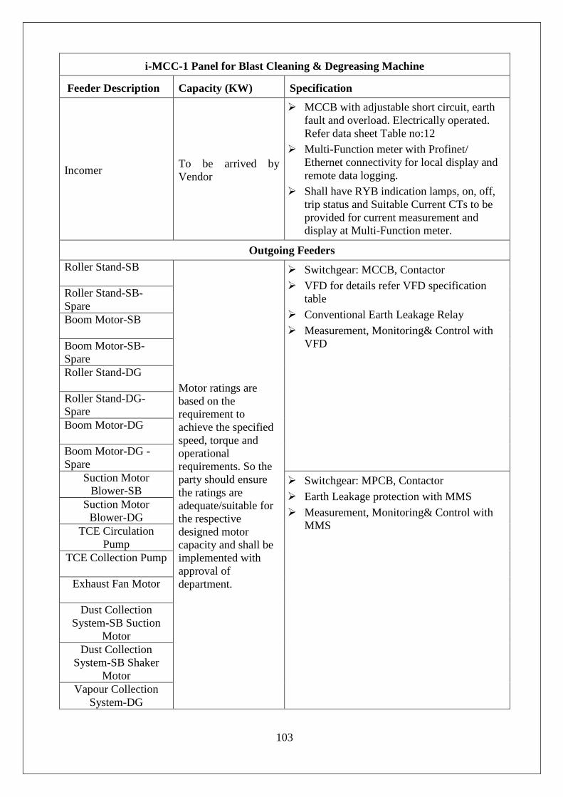
103
i-MCC-1 Panel for Blast Cleaning & Degreasing Machine
Feeder Description Capacity (KW) Specification
Incomer To be arrived by Vendor
MCCB with adjustable short circuit, earth fault and overload. Electrically operated. Refer data sheet Table no:12
Multi-Function meter with Profinet/ Ethernet connectivity for local display and remote data logging.
Shall have RYB indication lamps, on, off, trip status and Suitable Current CTs to be provided for current measurement and display at Multi-Function meter.
Outgoing Feeders
Roller Stand-SB
Motor ratings are based on the requirement to achieve the specified speed, torque and operational requirements. So the party should ensure the ratings are adequate/suitable for the respective designed motor capacity and shall be implemented with approval of department.
Switchgear: MCCB, Contactor
VFD for details refer VFD specification table
Conventional Earth Leakage Relay
Measurement, Monitoring& Control with VFD
Roller Stand-SB-Spare Boom Motor-SB
Boom Motor-SB-Spare Roller Stand-DG
Roller Stand-DG-Spare Boom Motor-DG
Boom Motor-DG -Spare
Suction Motor Blower-SB
Switchgear: MPCB, Contactor
Earth Leakage protection with MMS
Measurement, Monitoring& Control with MMS
Suction Motor Blower-DG
TCE Circulation Pump
TCE Collection Pump
Exhaust Fan Motor
Dust Collection System-SB Suction
Motor Dust Collection
System-SB Shaker Motor
Vapour Collection System-DG

104
Swiveling System Motor-SB
Swiveling System Motor-DG
Screw Conveyor
Bucket Elevator
Enclosure Motor-1 SB System
Enclosure Motor-2 DG System Classifer
Spare
Spare
Heater Bank ON & OFF
Switchgear: MCCB, Contactor (There shall be two contactors connected in series to avoid heater getting on in case of contact welding.)
Earth Leakage protection with MMS
Measurement, Monitoring& Control with MMS
Thyristor Controlled Bank
Switchgear: MCCB, Contactor
Thyristor Controller for details refer Thyristor Controller specification table
Conventional Earth Leakage Relay
Measurement, Monitoring& Control with Thyristor Controller:
Thyristor Unit shall have Communication Compatibility with PLC/SCADA to display Current/Voltage/Power/Healthy Status etc.,
Thyristor Controlled Bank-Spare
i-MCC-2 Panel for Resin Lining Machine
Feeder Description Capacity (KW) Specification

105
Incomer To be arrived by Vendor
MCCB with adjustable short circuit, earth fault and overload. Electrically operated.
Multi-Function meter with Profinet/ Ethernet connectivity for local display and remote data logging.
Shall have RYB indication lamps, on, off, trip status and Suitable Current CTs to be provided for current measurement and display at Multi-Function meter.
Outgoing Feeders
Boom Motor
Motor ratings are based on the requirement to achieve the specified speed, torque and operational requirements. So the party should ensure the ratings are adequate/suitable for the respective designed motor capacity and shall be implemented with approval of department.
Switchgear: MCCB, Contactor
VFD for details refer VFD specification table
Conventional Earth Leakage Relay
Measurement, Monitoring& Control with VFD
Boom Motor -Spare
Rollar Stand
Rollar Stand-Spare
Boom Swivelling Servo Motor
Servo Drives with MCCB/Semiconductor Fuses.
Boom Swivelling Servo Motor-Spare
Resin Pump - 1 Switchgear: MPCB, Contactor
Earth Leakage protection with MMS
Measurement, Monitoring& Control with MMS
Resin Pump - 2
Exhaust Blower-1
Exhaust Blower-2
Exhaust Blower-Spare Enclosure Motor Enclosure Motor-
Spare
• Feeders shall have the following features as per the above specifications
Switch Gear • MCCB: MCCB with adjustable short circuit, earth fault and overload protection
with necessary arrangements. Electrically operated. Specifications as per the Data sheets table no: 12
• MPCB: MPCB with adjustable short circuit, earth fault with necessary arrangements. Electrically operated. Specifications as per the Data Sheets Table no: 13
• Contactor: DOL starter with contactors of suitable rating. 4 NO + 4 NC contacts shall be provided in contactor for on/off status etc. Specifications as per the Data Sheets Table no: 15
Earth Leakage protection with MMS: • Earth Leakage protection shall be provided through MMS with External CBCT. In
case the selected MMS brand is not offering an integrated/add on Earth leakage

106
module (documentary proof from OEM to be submitted) microprocessor based ELR of PROK DVS can be used and interfaced through MMS digital input.
Conventional Earth Leakage protection: • Earth Leakage protection shall be provided with microprocessor based Earth
leakage relay with adjustable current/time and display of earth leakage current. ELR of Prok DVS make shall be Provided. Refer Data Sheet table no: 18
Measurement, Monitoring & Control with MMS: • Motor Management System
Measurement, Monitoring & Control with VFD: • VFD shall have Communication Protocol compatible with PLC/SCADA Main &
Redundant mode with Ring Topology
• All the feeders shall have sufficient no. of aux. contacts (NO & NC) in power contactor apart from the power contactors to use with Digital inputs of PLC and SCADA depending on the requirement (No add-on block for the contact multiplication is acceptable).
• For all design purposes, ambient temperature shall be considered as 50°C. Temperature rise shall be as per IS-8623
• All the feeders shall be compartmentalized.
• The Control and data acquisition is through PLC & SCADA. The PLC envisaged for this automation is dual redundant with criss-cross configuration. The i-MCC should use PROFINET/MODBUS TCP/ETHERNET communication Protocol and all feeder elements should be configured suitable to this dual redundant configuration. All feeder currents, VFD currents, on/off/trip status, On/Off commands, status, run status, feeder protection (EL,SC,OC, winding temp) should be communicated through communication cable.
• Ethernet switches required quantity and grouping shall be arrived by vendor with Dept approval (Refer Instrumentation and control section for details) shall be located in the i-MCC itself as a separate compartment.
• Necessary power supply unit, power supply online monitoring systems needs to be introduced and located in the same compartment.
• Network switch compartment shall have a glass door for easy monitoring.
• i-MCC communication cable (main & redundant -2 runs) should be laid from i-MCC to control room with sufficient extra length.
• The HMI/operator panels MMS (door display unit) are to be mounted on the front door of each compartment.
• All the above listed feeders should have iMCC/MMS modules for remote ON/OFF Command, status, current monitoring etc
• The Intelligent motor management system shall consist of necessary modules and add-ons for control and status monitoring, current/voltage measurement, operator panel with display unit for each motor feeder, ground fault monitoring, winding temp. monitoring etc.
• Panel shall have the 3-phase indication lamps in the metering cubicle controlled by 3-pole MCB.
• Voltage input to the Multifunction meter shall be routed through 3-pole MCB.

107
• Resin cast Current transformer shall be planned and secondary to be routed through terminal dis-connector.
• The incomer panel shall consist of MCCB with safety lock and key with suitable rating, which will be used to switch off power supply during EMERGENCY OFF.
• Control transformer can be planned for the control supply. Incoming and Outgoing MCBs shall also be planned for the same.
• Control transformer can be mounted on the front side / backside of the panel in any of the compartment with suitable ventilating arrangement.
• Sizing of the control transformer to be submitted for review and clearance before proceeding for the fabrication.
• All the feeders control supply to be routed through the suitable /adequate rating MCB having the provision of acquiring ON, OFF and TRIP Status.
• All the MCBs shall have the provision for ON, OFF and Alarm contact provisions. The same shall be wired for the control logics and SCADA information as per the requirement.
5.3.7 Motor Management System (MMS)
• Motor Management System means Electronic Modules capable of Monitoring, protecting, controlling motor feeders and as the nomenclature of the system is different among different makes term “MMS” will be used to represent the system. MMS shall provide protection, metering, control, monitoring, and historical logging for 3ɸ AC induction motors and Heater Bank currents up to 200A(min) using integral current transformers (CTs) or external CTs as applicable.
• The make of the motor management system should be of Siemens/ Schneider/Allen Bradley make MMS and the make shall be same as that of PLC selected.
• Protections: MMS shall provide all current and voltage based protections mentioned below:
Thermal overload
Current phase imbalance
Current phase loss
Current phase reversal
Long start
Jam (locked rotor during run)
Undercurrent
Over current
Ground Fault protection (internal)
Motor temperature sensor
Voltage phase imbalance
Voltage phase loss

108
Voltage phase reversal
Under / Over voltage
Any other additional protection feature as applicable.
• Monitoring:
It shall provide monitoring of all 3ph currents, ground current, avg. current, voltages, power, pf, active and reactive and energy, itshall have fault recording with all the current, voltage values for the last minimum 5 faults.
Ground fault protection & leakage protection shall be possible & it shall also have the provision to connect the (external) CBCT to MMS.
MMS shall have provision to directly connect to the temperature sensor, with or without expansion module
MMS shall monitor, display and communicate the temperature value (when connected with PT100 sensor)
• Communication
Device should have integrated communication port for the communicating through Modbus TCP, Ethernet, Profinet, communication suitable for SCADA/PLC system with media redundancy
• Control Voltage: 24VDC or 100-240V AC, 50 Hz
• The MMS Module shall have integral or through add on/Expansion modules Digital inputs
Programmable relay outputs
Temperature sensor input
CBCT input terminal.
• Configuration / Programming: MMS shall be programmable from HMI / PC.
MMS shall have prebuilt configuration modes for motor starters (DOL / star-delta)
MMS shall be configurable to operate as an overload relay
Custom logic for programming DI/DO shall be possible and the software shall have the provision for programming on structured text / Function block.
Digital outputs shall be potential free. Each output shall be capable to be connectable to different field voltages
• User Interface:
HMI or Memory plug shall have the capability to upload / download parameters to MMS

109
The address & other communication parameters shall be configurable from HMI or through address module.
HMI shall have the simple text display in English
• Earthing of intelligent modules to be connected to the Instrumentation earth (Earth strip available within 25 mtrs). Insulated copper of 2R x 1C x 10 sq.mm at both the ends of the i-MCC panel.
• Minimum 20% spare with respect to NO, NC terminals shall be provided in all compartments.
5.3.8 Operation Modes
Operating modes shall be provided as per the following.
Mode – I (Fully Automated) –
Automation Mode from Control Room
SCADA PLC iMCC CONTACTORMOTOR/HEATER BANK.
In this mode entire operation will undergo in Auto sequence mode with command from SCADA / PLC to VFD / MMS modules.
• All the process interlocks/logic operations will be executed in PLC and final command for on/Off / speed control etc., to VFD/MMS will be issued from PLC DO for respective feeder operation.
• In case of non VFD feeder PLC command will be issued to MMS module and MMS DO will switch on respective feeder motors. The contactor on/off status, ELR trip, MPCB/MCCB on/off status shall be wired as input to MMS module and logic is to be built in MMS software.
• This arrangement is required to distinguish clearly between process interlocks and electrical issues like short circuit/overload fault, Earth fault etc., to facilitate trouble shooting. on/off command from TCE Heater Bank-I will be issued from PLC PID temperature controller and analog command from PLC will be issued to thyristor controller for Bank-II. The current/fault messages shall be possible to be monitored from MMS operator panel and VFD AOP.
Mode–II (Discrete mode) –
Discrete Mode from Control Room
SCADA PLC iMCC CONTACTORMOTOR/HEATER BANK.
In this mode command is issued from local SCADA station to facilitate discrete operation of each feeder element with compliance of safety & process interlocks.
• In this mode also PLC DO will be taken as one of input to MMS and further compliance with respect to protections command will be issued from MMS DO.
• The current/fault messages shall be possible to be monitored from MMS operator panel and VFD AOP.
Emergency OFF requirements: There shall be two numbers of push button stations one each for Sand Blasting, Degreasing and Resin Lining machine iMCCs with interfacing of shunt trip coil in Each iMCC Incomer MCCB.

110
5.3.9 Electrical parameters Measuring & Monitoring iMCC requirements for interfacing with SCADA:
Panel shall be provided with Multifunction meter with Add-on DI / DO modules and PROFINET/ETHERNET module as applicable to motor management system selected. All The Devices Motor management system modules, Thyristor Banks, PAC Meter etc., in all feeders shall be suitable for communication protocol and dual redundant criss cross configuration used in PLC & SCADA system.
• Parameters from iMCC both digital and analogue are listed in following table. The list is indicative to assess digital/analog interface requirements. Exact list is to be finalized along with iMCC GA drawing and bill of material approval.
Table No. 2 Parameters – Digital & Analog
Feeder type Digital data Analog data
Incomer feeder
MCCB ON/OFF
Aux Contactor
Control Trfr off (supply to control Trfr cut off)
MCCB ON status
ELR trip status
MCB (Primary of Control transformer) ON/OFF Status
MCB (secondary of Control transformer) ON/OFF Status
Emergency OFF Status
-
Outgoing feeder with MPCB
Permanent local mode
MCB ON status (shunt trip coil supply)
MCB ON status (Control supply)
MPCB ON status
MPCB trip status
MCB trip status (control supply)
Panel start (P/B) stop(P/B)
Power contactor ON/OFF status
Three phase currents
Voltage(average)
Time for tripping OL
Last trip current
Restarting time after trip
Motor / feeder operating hours
(In addition to above for Thyristor Heater bank, Power)
Outgoing feeder with MCCB
MCB ON status (Shunt coil supply)
MCB ON status (Tr supply)
MCB ON status 24V DC supply
MCCB ON status
ELR trip status.

111
Feeder type Digital data Analog data
Outgoing feeder with Thyristor Controller
MCCB ON status
MCB ON status (Shunt coil supply)
Load circuit (Overcurrent, under current)
Mains voltage
Thyristor unit health
Multi-function Meter
Incomer Feeder -
Voltage L-L, L-N,
Current Per phase,
Neutral conductor current
Active power Per phase and total
Power factor Per phase and total
Frequency
THD voltage Per phase
THD current Per phase
5.4 MOTORS SPECIFICATIONS
5.4.1 General: Ratings:
All motor ratings given are based on internal mechanical design, However the final requirement is to achieve the specified speed and operational requirements. So the party should ensure the ratings are adequate/suitable and any change required may be adopted with department approval. Ensuring smooth functioning of all components as a system is the responsibility of the party and any change required in this regard to be brought to the notice of department and to be implemented with approval of department.
Cooling:
Some of the motors like Boom motor for Blasting & Degreasing Roller stand motor & trolley motor for Resin lining etc., are intended for low speed operations, where integral cooling arrangement may not be adequate. Such cases external cooling arrangement like separately powered cooling fan to be considered
Motor Specs Grouping
Motors with common specifications are grouped in one table and for motors specifications with special design requirements are illustrated separately with dedicated table of specifications.

112
5.4.2 Blasting cleaning & degreasing machine:
Table No. 3
ELECTRIC MOTOR SPECIFICATION- GEARED MOTOR for BOO M DRIVES
Make SIEMENS/SEW/PBL or any other make with dept approval
RPM 0.15 / 1.1 RPM
Motor capacity 0.25 KW
Motor type HELICAL BEVEL GEARED
Torque 13300 NM
Shaft Single output shaft
Mounting Foot/Flange Mounting
Operating Voltage Up to 440V
Operating Frequency 5 - 50 Hz VFD Controlled
Duty class S1
Protection IP55 Or Better
Insulation class F or Better
Standard Motors shall comply IS:325 /IEC :60034-1
Brake Integrated with Manual release.
Operation with VFDs Motor shall be possible to use with PWM Drive Converter with voltage rise time of Ts>0.1µs at the Motor Terminals. Bearing currents and insulation strength requirements for compatibility with VFD.
ELECTRIC MOTOR SPECIFICATION –ROLLER STANDS
Make Make: Kirloskar /Crompton Greaves/Bharat Bijili /CEMP /Marathon / Siemens/SEW/PBL or any other make with dept approval
RPM 1000
Rated Power 7.5 KW
Motor type Induction motor
Shaft 42.00 mm Dia
Operating Voltage 415 V ± 10 %, 3 Phase
Operating Frequency 50 Hz ± 3 %
Duty class Continuous S1
Frame size 160M
Protection IP 55 or better
Insulation class F and temperature rise limited to class B

113
Efficiency IE 2 or Better
Thermister Embedded in windings to monitor winding temperature and trip system upon high winding temperature.
Standard Motors shall comply IS:325 /IEC :60034-1
ELECTRICAL MOTOR WITH COMMON SPECIFICATIONS:
• Suction Blower Motors-Sand Blasting & Degrasing -2 nos: 3.7 KW
• TCE Circulation Pump: 1.5 KW
• TCE Collection Pump: 1.5 KW
• Exhaust Fan Motor: 1.5 KW
• Dust collection System SB Suction Motor-7.5 KW
• Dust collection System SB Shaker Motor-0.75 KW
• Vapour Collection System-DG-7.5 KW
• Swiveling System Motor-SB-0.75 KW
• Swiveling System Motor-DG-0.75 KW
• Screw Conveyor-1.5 KW
• Bucket Elevator-0.75 KW
The motor capacity should be selected such that motor shall draw only 80% of rated current at full load. Design calculations to be submitted towards arrival of motor power rating and approval to be obtained Make Make: Kirloskar /Crompton Greaves/Bharat Bijili /CEMP /Marathon /
Siemens/SEW/PBL or any other make with dept approval
RPM 1500
Motor type Induction motor
Operating Voltage 415 V ± 10 %, 3 Phase
Operating Frequency
50 Hz ± 3 %
Duty class Continuous S1
Protection IP 55 or better
Insulation class F and temperature rise limited to class B
Efficiency IE 2 or Better
Thermister Embedded in windings to monitor winding temperature and trip system upon high winding temperature.
Standard Motors shall comply IS:325 /IEC :60034-1

114
5.4.3 Resin lining machine:
Table No. 4
ELECTRIC MOTOR SPECIFICATION-BOOM TROLLEY
Make SIEMENS/ SEW/PBL or any other make with dept approval
RPM 1360 RPM
Motor capacity 0.25 KW
Motor type HELICALWORM,GEARED MOTOR
Motor Gear Output Speed Range:
0.15-1.15 RPM (Corresponding to 5Hz - 50Hz)
Torque 1818 NM
Shaft M20 X 42 deep tapped hole in the output shaft
Mounting Flange Mounting or Foot Mounting as applicable.
Operating Voltage Upto 440 V
Operating Frequency 5-50 Hz
Duty class S4
Protection IP: 55 or better
Insulation class F or better
Standard Motors shall comply IS:325 / IEC :60034-1
Brake Integrated with Manual release.
Operation with VFDs Motor shall be possible to use with PWM Drive Converter with voltage rise time of Ts>0.1µs at the Motor Terminals. Bearing currents and insulation strength requirements for compatibility with VFD.
ELECTRIC MOTOR SPECIFICATION-ROLLER STAND
Make SIEMENS/ SEW/PBL or any other make with dept approval
RPM 1000 RPM
Motor capacity 7.5 KW
Torque 74.56 NM
Dia of Motor Shaft 42 mm
Mounting Foot Mounting/Flange Mounting
Frame Size 160M
Operating Voltage Up to 440 V
Operating Frequency 5-50 Hz
Duty class S1

115
Protection IP55 or Better
Insulation class F or Better
Standard Motors shall comply IS:325/IEC :60034-1
Brake Integrated with Manual release.
Operation with VFDs Motor shall be possible to use with PWM Drive Converter with voltage rise time of Ts>0.1µs at the Motor Terminals. Bearing currents and insulation strength requirements for compatibility with VFD.
ELECTRIC MOTOR SPECIFICATION-SERVO MOTOR for LANCE SWIVELING
OF RESIN LINING MACHINE
Make SIEMENS/SEW/PBL or any other make with dept approval
RPM 60 RPM
Motor capacity 0.5 KW
Motor type SERVO MOTOR
Torque 77 NM
Mounting Flange Mounting or Foot Mounting as applicable.
Operating Voltage Upto 440 V
Operating Frequency 5-50 Hz
Protection IP55 or Better
Insulation class F or Better
Brake Integrated with Manual release.
ELECTRIC MOTOR WITH COMMON SPECIFICATIONS:
• Resin Pump-1&2: 0.75KW • Exhaust Blowers 1&2: 3.75KW • Enclosure Motor: 1.5KW
The motor capacity should be selected such that motor shall draw only 80% of rated current at full load. Design calculations to be submitted towards arrival of motor power rating and approval to be obtained
Make Make: Kirloskar /Crompton Greaves/Bharat Bijili /CEMP /Marathon / Siemens/SEW/PBL or any other make with dept approval
RPM 1500 as per vendor requirements
Motor type Induction motor
Operating Voltage 415 V ± 10 %, 3 Phase
Operating Frequency 50 Hz ± 3 %
Duty class Continuous S1
Protection IP 55 or better

116
Insulation class F and temperature rise limited to class B
Efficiency IE 2 or Better
Thermister Embedded in windings to monitor winding temperature and trip system upon high winding temperature.
Standard Motors shall comply IS:325 /IEC :60034-1
5.5 VFD SPECIFICATIONS:
5.5.1 VFD requirements for servo motor:
There are two numbers of servo drive feeders (Main & Spare) and accordingly servo drives are to be planned with necessary protection features and other desirable features suitable to the servo motor considering servo motor torque requirements. Vendor has to provide VFD details for approval.
5.5.2 VFD requirements for induction motor: Table No.: 5
VFD Specifications For Induction Motor Description Essential Specification
Quantity 12 Nos
Make Siemens / ABB
Main voltage 380-480 V , 3 Phase
Input Frequency 48-63 Hz
Output rating One size higher standard Drive rating of selected motor full load rating
Control requirement The drive should start & stop in slow speed and in between higher than start speed .The start, stop and acceleration should not cause any considerable jerk.
Overload capacity 150 % for 60 sec
Digital inputs 6 Nos programmable (minimum)
Analog inputs 2 Nos programmable (0-10 V, 0-20 mA, and -10 to +10 V) (minimum)
Relay outputs 3 Nos programmable (minimum)
Analog outputs 2 Nos programmable (0-20 mA) (minimum)
Safety guidelines IEC 61800
Ambient Temperature 50 Deg C
Choke or filter Choke/Filter of suitable rating to limit THD as per IEEE519
Operator panel Advanced Operator panel (AOP)mounted on panel cubicle door
5.6 THYRISTOR CONTROLLER SPECIFICATIONS:
Table No.: 6 Specifications of Thyristor controller
Description Description Quantity TCE Distillation Tank (18kW) -2No’s

117
Make AE
Model ThyroPX-
Main voltage 380-480 V, 3 Phase
Input Frequency 47-63 Hz
Load type 3phase resistive connected star configuration
Controller type 3Legged, Digital Processor, 32 Bit or Higher
Firing mode TAKT (Burst Firing), VAR (Phase Angle) and SSSD (Soft Start & Soft Down )
LED Indication LED indications 4 Green, 3 Red LEDs (Freely Configurable Type)
Control mode option required
Vrms, V2, Irms, I2, P or OPEN LOOP selectable with Highest accuracy of 0.5% in V & I Control & 1.0% in P Control
Display Unit Local Display and Monitoring unit for Configuration and Parameterisation with COPY & SAVE function
Removable type display: The Local Display shall be equipped with a graphic touch display and SD card. Process data recorder feature shall be available as standard. Display shall also have following option: • Line chart (6 values Min) • Operation display (6 values, Min) • Bar chart (4 values, Min) • Data logger • Multi colour Line / Bar chart shall be available
Communication Features: Communication Feature – Required for digital data transfer with Motor Management System (MMS)
ProfiNET-V3 / Ethernet IP Communication shall be a Plug & play card type (Communication to be selected based on PLC/MMS Communication Protocol selected)with following key features: - Minimum of 3 free digital Inputs (Configurable for Local / Remote Setpoint change, etc) - The ProfiNET / Ethernet plug-in card shall have two RJ45 ports which are equipped with a switch functionality which allows a line topology to be constructed - BumplessSetpoint Transfer shall be a key feature
Digital Load synchronisation
Automatic Synchronisation of Multiple power controller for load optimisation shall be available as standard
Digital inputs 6 No’s programmable (minimum)
Analog inputs 3 No’s programmable (0-10 V, 0-20 mA, and -10 to +10 V) (minimum)
Relay outputs 3 No’s programmable (minimum)
Analog outputs 3 No’s programmable (0-10V / 0-20 mA) (minimum) Configurable
Ambient Temperature 45Deg C Choke or filter Choke/Filter of suitable rating to limit THD as per IEEE519, if required Configuration method a. PC software or Through Local Display
Short circuit test Compliance Shall have 100KA Short circuit test certificate from any International Test Lab

118
5.7 HEATER BANKS SPECIFICATIONS: Table No.: 7
Specifications of -Heater Bank-TCE Distillation tank Description Essential Specification
Electrical Specs
Bank Capacity No of heating elements
Bank –I: 18 kw and Bank II :18 Kw
No of elements : Bank I-Three Nos Bank-II Three Nos, Each element 6kw(standard immersion heater working on 240V AC)
Heater control ON/OFF control for Bank 1, and Thyristor control for bank 2
TCE level control Automatic TCE level controller using level sensor
Connection There shall be a local power distribution board mounted on Tank outer wall consisting of 6 numbers of MCB (one for each heater) & two ELCB one for each bank with Bus bar arrangement in star 4 wire configurations for both heater banks. There will be one heater in each phase and Neutral in each bank. Teflon wires or suitable heat resistance wires shall be used for terminating heaters from Bus bar in local DBSize of the wire is 200% with respect to the heater drawing current.
Capacity 36 Kw
No of Banks 2Nos
Supply Voltage 415V+/-10% 3phase, 4 wire
Connection 3Phase Star Configuration
Individual Heating Element Voltage
1 Phase, 240V AC
Heater tube material INCONEL
Heater Material Nichrome 80/20
Insulation Material Magnesium oxide
5.8 POWER & CONTROL CABLES:
5.8.1 Party shall supply Power cables, control cables, cable trays as per the specifications in the data sheets and shall also carryout cable laying on wall /trench /cable tray as applicable. All the miscellaneous items like cable glands, lugs, ties, fixers shall also be supplied by the party.
5.8.2 Power wiring with suitable rated armoured cables as per load requirements shall be provided. The cable make shall be as per specifications (datasheets).
5.8.3 The power wiring shall be carried out for the following
5.8.4 PCC to iMCC (Incomer)
5.8.5 iMCC to Motor & Heater Loads ( for both iMCCs)
5.8.6 The cables shall comply with LT voltage level 1100V, Armoured with XLPE insulation as per IS:7098. The minimum size of cable shall be 4 sq. mm copper conductor for all

119
power wiring. All feeders shall be with copper conductor cables. The power wiring shall be carried out with necessary saddles, clamps, cable tags, glands, etc.
5.8.7 Necessary cable glands and suitable lugs with respect to the feeder requirement and field equipments are in the scope of supplier.
5.8.8 All the power and control cables which are routed from i-MCC panel are to be routed through perforated cable tray with proper cover inside the cable trench as per the direction given by the department.
5.8.9 Wiring shall be neatly bunched, adequately supported and properly routed through cable alley (duct) to allow easy access and maintenance.
5.8.10 The ferrules shall be of the ring type and of non-deteriorating material.
5.8.11 They shall be firmly located on each wires so as to prevent free movement.
5.8.12 Cable Laying:
• Power, Control and Communication cables shall be laid in trenches and cable trays as applicable.
• Medium voltage and control cable shall be separated from each other by adequate spacing or by running through trenches or cable trays.
• The lengths indicated in the cables schedule are only approximate. The contractor shall ascertain the exact length of cable for a particular feeder by measuring at site. All cable routes shall be carefully measured and cables cut to the required lengths, leaving sufficient lengths for the terminations of the cable at both ends.
• Cable shall be laid in RCC trench (underground trench) or in surface tray.
• Cable installation shall be provided minimum cable bending radii as recommended by manufacturer.
• Cables shall be neatly arranged in the trenches/trays in such a manner that crisscrossing is avoided.
• All cables shall be identified close to their termination point by cable tags.
5.8.13 Cable Termination:
• Wherever copper to aluminum Interconnections are made, necessary bimetallic washers shall be used.
• In case of control cables all cores shall be identified at both ends by their terminal numbers by means of PVC ferrules for core size. Wire numbers shall be as per schematic wiring/inter-connection diagram. All unused spare cores of control cables shall be nearly bunched and ferruled with cable tag at both ends, for future use.
• Contractor shall drill holes for fixing glands wherever necessary. Gland plate shall be wherever more number of cables are terminated. All unused cable entries on equipment/panels shall be plugged or sealed.
• The cable shall be terminated at electrical equipment/switchboard through glands of proper size.
• Before energizing, the insulation resistance of every circuit shall be measured from phase to phase, phase to neutral and from phase/neutral to earth. The approximate cable length requirements are listed in below mentioned table.

120
5.8.14 Control Wiring:
• The control wiring shall be armoured with minimum copper conductor size of 2.5 sq. mm of XLPE/PVC insulation, voltage grade 660V/1100V as per IS: 1554/7098. The control wiring shall consist of following:
• Master Emergency OFF at Control room shall be hardwired with iMCC panel incomer MCCB trip circuit.
• iMCC panel to Control room
5.8.15 Cable Trays
• Cable trays shall be to carrying cable laying both inside and outside the facility. Power cables, control cables and communication cables shall be layed separately in different cable trays.
• The cable tray shall be wire mesh cable tray of CABLOFIL (LEGRAND) or suitable cable tray/make with Dept approval.
• Supply and installation of Cable tray is in the scope of the party. Civil cable trenches shall be provided by the department.
5.8.16 List of Cables:
• The quantity of Power & control cables required to meet various interfacing field elements is specified below. The details are indicative and party shall meet extra cable requirements in case of requirement.
• The size of the cable should be decided based on the expected highest load in the cable adding 50% cushion. Calculations arriving the cable sizing should be submitted for approval. Any other cable not listed below but required for completion of the system/proper working of the system shall be provided by the party without any additional cost.
POWER CABLES QUANTITIES:
Table No: 8 Blast Cleaning & Degreasing Machine
Cable Description Tentative Capacity
Anticipated Length(mts) Remarks
Cable from PCC to Imcc-1-2 Runs 4 sq.mm X 4C
-Al 300
Cable from iMCC to all Motors in feeder list
4 sq mm X 3C-Cu 1500
Cable from iMCC to Water Heater Banks-2 nos-18
KW
4 sq mm X 4C-Cu 200

121
Resin Lining Machine
Cable from PCC to iMCC-2 35 sq.mm X 4C
-Al 100
Cable from iMCC to all Motors in feeder list
4 sq mm X 3C-Cu 700
5.9 ERECTION & COMMISSIONING:
5.9.1 The party has to erect i-MCC over the designated trench, with channels L angles and fasters as required.
5.9.2 Power connection to the i-MCC including incomer connections from PCC to be completed.
5.9.3 Erection of all electrical systems is in the scope of party and shall be under the supervision of an engineer deputed by the party.
5.9.4 All control interfaces & control wiring from i-MCC to PLC and other elements to be carried out.
5.9.5 Soft copy of drive parameters in CD/DVD shall be provided.
5.9.6 The Integration of iMCC with PLC & SCADA shall be carried out at SDSC, SHAR.A team of Authorised Engineers (M/S Schneider / Siemens / Allen Bradley) who has expertise in VFD& MMS shall be deployed @ SDSC, SHAR for integration, commissioning and testing of iMCC with PLC/SCADA and shall be made available till completion of first live trial. They should demonstrate all functional and protective features.
5.9.7 The Vendor shall employ (BS Techno LTD Chennai or AE) authorised person for commissioning of Thyristor Controller.
5.9.8 All cable laying and suitable termination, loop checking, interfacing and trial runs is in scope of supplier. Necessary works like clamping, crimping, ferruling etc. is in party’s scope.
5.10 STANDARDS:
The Electrical systems shall conform to respective IS/IEC specification with latest amendments. An indicative list is given below
Table No.: 9 List of Standards
S No Description of the Item Standard
1 Motors IEC 60034 / IS 325
2 PVC Cables IS 1554
3 XLPE Cables IS 7098
4 LV switch gear and control gear IEC 13947

122
S No Description of the Item Standard
5 General requirements for switch gear and control gear for voltages not exceeding 1000 V
IS 4237
6 Current Transformers IS 2705
7 MV Panel – Factory built assemblies of switch gear and control gear for voltages up to and including 1000 V AC and 1200 V DC.
IS 8623
5.11 TECHNICAL SPECIFICATIONS (DATA SHEETS): Party shall supply the items as per the following specifications.
Table No:10 Specifications of Switch Gear - ACB Switch gear ACB
Maximum rated current(In max) Standard rating higher than 150% of the calculated maximum current.
Rated short circuit breaking capacity Ics(=Icu)
85kA or higher
Rated insulation voltage Ui 1000V
Rated operational voltage Ue 690V
Rated Impulse withstand voltage Uimp
12kV
Standard IEC60947-2
Over current release features Overload protection(L-tripping), Short time delay short circuit protection(S-tripping), Instantaneous short-circuit protection(i-tripping), Neutral conductor protection (N-tripping), Earth fault tripping.
Load monitoring, short circuit protection and overload protection switchable to I2t, changeable parameter set. Graphical display
Communication via Ethernet / Profibus ,parameterization by communication
Motor operating mechanism Working on 208-240 V AC
Auxiliary releases Shunt trip, closing coil, signaling switch, Capacitor energy storage unit for shunt release
Indicators and operating elements Locking set, Make-break operation counter, Electrical on pushbutton, Emergency off pushbutton

123
Table no:11 Specifications of Switch Gear - MCCB Description Essential Specification
Maximum rated current
(In max)
Standard Rating
• Incomer Feeder- 150% Rated Current
• Motor Loads-150% Rated Current
• Other loads-125% Rated Current
Rated short circuit breaking capacity Ics(=Icu)
55kA for incomers and main feeder switches,35kA for sub feeders
Rated insulation voltage Ui 1000V
Rated operational voltage Ue 690V
Standard
Circuit breakers shall comply with the following standards:
• IEC 60947-2
• IEC 60947-1
• Isolating features in accordance with IEC 60947-3
Over current release features
• Overload protection (L-tripping), Short time delay short circuit protection(S-tripping), Instantaneous short-circuit protection (i-tripping), Neutral conductor protection (N-tripping), Earth fault tripping.
• Load monitoring, short circuit protection and overload protection switchable to I2t.
• Communication via Ethernet / Profibus, parameterization by communication
Auxiliary releases Shunt trip, closing coil, Signaling switch
Model Latest series meeting the above specification
Make M/s Siemens / L&T / Schneider
Table No:12 Specifications of Switch Gear - MPCB
Description Essential Specification
Maximum rated current
(In max)
Standard rating higher than 120% of the motor name plate current.

124
Description Essential Specification
Rated short circuit breaking capacity Ics(=Icu)
35kA or higher
Standard IEC60947-2, IEC60947-4-1
Releases Relay Function
Aux Contacts 1NO + 1NC
Add ons Additional 1NO+1NC, short circuit signaler with 1NO+1NC (Preferable)
Model Latest series meeting the above specification
Make M/s Siemens / L&T / Schneider
Table No:13 Specifications of Switch Gear - MCB Description Essential Specification
Maximum rated current
(In max)
Standard rating higher than 120% of the calculated maximum current.
Rated short circuit breaking capacity Ics(=Icu)
10kA or better
Rated operational voltage Ue 415V
Standard
Circuit breakers shall comply with the following standards:
• IEC 60898-1 or IS 8828
Curve C Curve for highly inductive loads
Model Latest series meeting the above specification
Make M/s Siemens / L&T / Schneider / Legrand

125
Table No:14 Specifications of Switch Gear - Contactor Description Essential Specification
Maximum rated current
(In max)
Standard rating higher than 200% of the calculated maximum current.
AC3 current rating at 415V to be considered.
AC4 for inching operational requirements
AC1 for resistive loads
Rated short circuit breaking capacity Ics(=Icu)
50Ka or better
Rated operational voltage Ue 415V
Control Coil Voltage 230V AC
Standard IEC 60947, IS13947
Aux Contacts Required 2NO + 2NC (minimum)
Model Latest series meeting the above specification
Make M/s Siemens
Table No:15 Specifications of Switch Gear – Aux Contactor Description Essential Specification
Control Coil Voltage 230V AC
Standard IEC 60947, IS13947
Aux Contacts Required 4NO + 4NC
Model Latest series meeting the above specification
Make M/s Siemens
Table No:16 Specifications of Switch Gear - OLR Description Essential Specification
Trip Class 10
Standard IEC 60947, IS13947
Aux Contacts Required 1NO + 1NC (minimum)

126
Model Latest series meeting the above specification
Make M/s Siemens
Table No:17 Specifications of Earth Leakage Relay Description Essential Specification
Detail Microprocessor based Earth Leakage Relay with CBCT of Resin Cast
Model MPEL-02
Current Range 30 mA – 3000 mA
Current Range Setting 18 steps
Tripping time 0 – 5 sec
Auxiliary Voltage 85 – 275 V AC
CBCT Type and Size Resin cast Circular
Contact rating 8A, 250V AC / 8A 30V DC 2 C/O Contacts
Mounting Flush
Dimensions 96 mm x 96 m x 70 mm (W x H x D)
Make Prok DVs
Table No:18 Specifications of Power & Control Cables
Description Essential Specification
Type Armoured Copper Conductor
Size
Power cable – 4 sq mm. (minimum)
Control cable – 1.5 sq. mm. (minimum)
Profinet/Ethernet cable-As per standard
Make – 1.1 KV LT Power Cable
CCI / Universal / Finolex / Polycab / IGUS / Gloster / Lapp / KEI / Havells
Make – 1.1 KV LT PVC Control Cable
Finolex / RR Kabel / Gloster / Lapp / KEI / Havells / Polycab / IGUS
1.1 KV Panel Wire
Finolex / RR Kabel / Lapp / Havells


127
SECTION -D
Annexures

128
Annexure – I
LIST OF SUGGESTED MAKE / VENDORS FOR BOUGHT OUT ITE MS
Mechanical items :
1. Blast Cleaning Machine
S. No.
Items Specifications Make/Model Make/Model selected by supplier
1 Blast generator and cabinet integrated with screw conveyor, bucket elevator
As mentioned in 2.3
M/s. NESCO INDABRATOR
2 Plummer block for boom drive motor
As per Drawing
FYH, NTN
3 Geared motor boom drive POWERBUILD
4 Plummer block for boom support roller
FYH, NTN
5 Ball bearing for Skew arrestor SKF, FAG
6 Gear box for roller stand ELECON, RADICON, SHANTI GEARS
7 Coupling for roller stand LOVEJOY
8 Plumber box for roller stand FYH, NTN
2. Degreasing Machine S.
No. Items Specifications Make
1 Collection pump and Spray pump As mentioned in 2.2 of Section C
M/s. JOHNSON PUMPS
2 Plummer block for boom drive motor
As per Drawing
FYH, NTN
3 Geared motor boom drive POWERBUILD
4 Plummer block for boom support roller
FYH, NTN
5 Ball bearing for Skew arrestor SKF, FAG
6 Gear box for roller stand ELECON, RADICON, SHANTI GEARS
7 Coupling for roller stand LOVEJOY

129
8 Plumber box for roller stand FYH, NTN
3. Resin Lining Machine
1. Geared motor for trolley drive system
As per Drawing
PBL or equivalent on prior approval
2. Plummer block Lance swiveling FYH, NTN
3. Coupling for Lance arrangement LOVEJOY
4. Bearing for Skew Arrester SKF, FAG
5. Plummer block for roller stand FYH, NTN
6. Gear Box ELECON, RADICON, SHANTI GEARS
7. Coupling LOVEJOY
8. Spray Gun Pressure fed spray gun with nozzle set up
Make: BULLOWS Model: 230 with 2070X63 PM air nozzle
9. Nitrogen Regulator
Nitrogen double stage regulator Inlet-300 Bar & Outlet- 10 Bar
Make: ESAB Model: DURA N-10
Electronic and Instrumentation Items :
S.
No
Item Specifications Make
1 PLC
As per technical
specifications in
the document
Siemens/ Schneider/ Rockwell
2 PLC Programming Software
Siemens/ Schneider/ Rockwell (Professional Full Version)
3 8/16 Channel AI Non IS IO Modules
Siemens/ Schneider/ Rockwell
4 16 /32 Channel DI Non IS IO Modules
Siemens/ Schneider/ Rockwell
5 4/8 Channel AO Non IS IO Modules
Siemens/ Schneider/ Rockwell
6 16/32 Channel DO Non IS IO Modules
Siemens/ Schneider/ Rockwell
7 4 Channel AI IS IO Modules Siemens/ Schneider/ Rockwell
8 8 Channel DI IS IO Modules Siemens/ Schneider/ Rockwell
9 SCADA Siemens/ Schneider/ Rockwell

130
10 SCADA work Station
As per technical
specifications in
the document
HP/ Dell
11 Thin Clients HP/Dell
12 L2 - Network Switch Extreme/ Antaira / Moxa/Schneider/ Siemens
13 L3 - Network Switch Extreme/ Moxa / Cisco / Allied Telesys/Planet / HP
14 24 VDC Power Supply Siemens/ Pheonix /Pulse / Aplab
15 Panels Rittal / Adarsha / Pyrotech
16 Network enclosures Valrack/ APC/ Rittal/ Adharsha/ FCI/ 3M
17 Control Console
Pyrotech electronics private limited/ Adarsha / Evans / Winstead
18 RTD Sensor
Rosemount / Omega/ Wika/ Baumer/ Tempsens/ Nagman/ Exotherm
19 Temperature Transmitter Rosemount/ Siemens
20 Pressure Transmitter (0-55 Bar) Rosemount 3051/ Siemens
21 Vacuum Transmitter (0-760 Torr)
Rosemount 3051/ Siemens
22 Vacuum Transmitter (0-20 Torr) Rosemount 3051/ Siemens
23 Level Transmitter (Water) Rosemount/ P&F / Baumer / Vega/ ifm
24 Distance/ Angle measuring encoder
P&F/ IFM/ Hengstler/ Siemens
25 Water Flow Switch IFM/ Switzer / Danfoss/ P&F
26 Proximity sensor P&F
27 Control Valve
Fisher/ El-o-matic/ Micropneumatic/ Flowserve/ MIL controls/ Siemens
28 Push buttons/ Emergency Push Buttons/ Indication Lamps/ hooters/MCCB/MCB
Siemens/ Schneider
29 Relay (Command) OEN, OMRAN, Phoenix, P&F

131
30 LED TV
As per technical
specifications in
the document
LG/ Panasonic/ Samsung/ Sony/ Toshiba
31 Load cells Sartorius/ Mettler /PreciaMolen/LCGC
32 Power, Signal Cables & Control Cables
Uniflex, Thermocables, Thermocabs, Delton, Delta, Lapp, Paramount cables, Polycab, RPG, CMI
33 Fiber Optic Cable HFCL, 3C, SCHNEIDER, TYCO
34 AC Voltage SPD (Type 1 / 2/3 with VG Technology) / DC Voltage/ Ethernet SPD
Pheonix/ Dhen/ CItel
35 Armored/ Flexible CAT6 / 7 STP Cable
Belden/ Schneider
36 Terminal Blocks/Fuse TBs Phoenix/ Wago/ Weidmuller
37 Double/ Single compression Glands
Baliga/ Comet
Electrical Items :
1 ACB
As per technical
specifications in
the document
Siemens / L&T
2 MCB Siemens / Schneider
/ Legrand
3 MCCB Siemens / Schneider
/ L&T
4 MPCB/CONTACTOR/OLR/Aux Contactor Siemens
5 Timer Siemens / L&T
6 Line / Power Monitoring Relay Siemens
7 Limit Switches Siemens / L&T
8 CT Kappa / AE
9 CT Current Transducer / Voltage
Transducer
Rishab / M-System
/AE
10 Current Transducer LEM

132
11 Earth Leakage Relay
As per technical
specifications in
the document
PROK DVS
12 FLP Items Baliga / FCG /
STAHL
13 Intrinsic Safe Items P&F
14 Power Cable
Havells / Finolex /
CCI / Universal /
Polycab / IGUS /
Gloster / Lapp /KEI
15 Control Cable
Havells / Finolex /
Polycab / IGUS /
Gloster / Lapp / KEI
/ RR Kabel
16 Panel Wiring Cable Havells / Finolex /
Lapp / RR Kabel
17 Motor Management System
(MMS)
Siemens / Schneider
/ Allen Bradley
18 Soft Starter Siemens
19 Thyristor Power Controller AEI
20 Digital Panel Meter
AE / RISHAB /
Schneider / L&T /
ABB / MCIH / PMA
/ Conzerve
21 Multi-function Meter Siemens
22 Push Buttons Siemens
23 Indication lamps Siemens / L&T
24 IS Indication Lamps BEKA
25 iMCC Integrator
M/s SIEMENS LTD M/s ALLEN BRADLEY LTD M/s ADARSHA CONTROL & AUTOMATION PVT. LTD, Chennai M/s AUTOSYS ENGINEERING PVT LTD

133
M/s KASA ANLAGEN PVT LTD, Chennai M/s CHEMIN CONTROLS PVT LTD , Pondicherry M/s RSP CONTROLS LTD, Chennai M/s FORMOPLASTIC CONTROLS (P) LTD
Note: However, in case of difficulties in obtaining any of the listed makes any other makes confirming specifications can be considered with the approval of dept. Party should submit the details of difficulty in obtaining the listed item with documentary evidence and detailed data sheet of alternate make in offer.

134
Annexure-II
LIST OF SPARES for the SPECIAL PURPOSE MACHINES List of the spares given below are minimum required to be supplied along with machine and shall be similar to the item used in the machine.
Sl. No ITEM DESCRIPTION QTY (Nos)
A) Mechanical Spares for Blast Cleaning& Degreasing Machines 1. Rubber ring for Mushroom valve 10 2. Mushroom valve 6 3. Mixing tube assembly 16 4. Tungsten carbide nozzle 6 5. 15m length 1 ½ inch bore Blasting hose 10 6. Service tools 1 set 7. Dust collector bags 100 8. Screw conveyor Bearings 2 9. Elevator bearings 2 10. Elevator bucket 10 11. Vibro screen 3 12. Drive Roller Bearing 1 13. Drive Roller Bearing Housing 1 14. Idler Roller Bearing 1 15. Idler Roller Bearing Housing 1 16. Blast cleaning Boom Assembly Bearing 1 17. Blast cleaning Boom Assembly Bearing Housing 1 18. Drive Rollers 2 19. Idler Rollers 2 20. Cabinet screw arrestors 2
21. 15m Teflon lined SS convoluted flexible hose of 1” size with slip on female end fittings on both ends.
2
22. Immersion pipe heaters sheathing 20 B) Mechanical Spares for Resin Lining Machine
23. Sprocket for Trolley drive system 2 24. Chain Roller 6
25. Mobile Trolley wheel bearing 2 26. Nitrogen manifold 1 27. Drive & Idler rollers 2
C) Electrical Spares(Rating based upon the requirement) 1. Thyristor (for TCE distillation tank-Heater Bank) 1 2.. MMS module full set 2 3. M.MCCB spare SB & DG for Incomer 1 4. M.MCCB Spare for Resin Lining machine I/C 1 5. MPCBs 10 6. CONTACTOR 20
7. MMS CONFIGURING SOFTWARE WITH LICENSE (IF ANY) IN LAPTOP WITH INTERFACING ACCESSORIES
1
8. Electric motor for blasting machine boom drive 1 9. Electric motor (SERVO) for Resin lining machine lance swiveling 1

135
10. Electrical motor for Resin lining machine- Boom trolley movement 1 11. Electrical motor for Resin lining – Roller Stand 1 12. Heater Elements for TCE distillation system 20
NOTE: The spares listed above are to be supplied along with the machines. Any other spares required for carrying out Maintenance after the warranty period may be listed out separately along with cost. Cost of these additional spares shall not be combined with the cost of spares given above. The cost of additional spares suggested by the bidder shall be quoted separately in e-procurement portal and will not be considered for evaluation of bids.
D) Instrumentation & Control Systems spares
1.
Hot Standby PLC and I/O modules 1 No Hot Standby set with synchronizing cables and 2 nos of each type of I/O module
2 Network Switch 2 no 3 SCADA workstations 1 no 4 SCADA thin clients 1 no 5 24 VDC Power Supply 2 nos 6 Temperature / Pressure / Level Transmitter 3 each type 8 Encoder 2 each type 9 Proximity sensor 10 nos.
10 Push buttons/ Emergency Push Buttons/ Indication Lamps/ hooters/MCCB/MCB
5 nos. each type
11
Relay 20% of total number of field elements (Minimum 1 no)
13 PTZ CCTV Camera (WP) 1 no 14 Humidity Monitor 1 no
15 Surge Protection Devices 20% of total
number 16 Boom Camera 2 no.s

136
Annexure –III
LIST OF DRAWING
1. BLAST CLEANING MACHINE A) General assembly of machine
Sl. No Drawing No. Sheet No. Description 1 10-03-67-01-
001/R1 1 of 1 General assembly of Blast Cleaning Machine for S-
139 hardware/HIL-2, SPROB B) Roller Stand & Support Structure
1
10-03-67-01-002/A1/R1
1 of 5 General Assembly of Roller Stand of Blast Cleaning Machine.
2 2 of 5 Roller Stand Support Structure of Blast Cleaning
Machine 3 3 of 5 Drive Roller assembly of Blast Cleaning Machine 4 4 of 5 Idler Roller 5 5of 5 Skew arrester assembly& details C) Boom & Lance System
1 10-03-67-01-003/A1/R1
1 of 3 Boom assembly of blast cleaning machine
2. 2 of 3 Boom details 3 3 of 3 Lance assembly details D) Boom support & Drive System
1. 10-03-67-01-004/A1/R1
1 of 1 Boom Support Structure with rollers
2 10-03-67-01-005/A1/R1
1 of 1 Boom Drive system with support stand
E) Boom Support & Drive System
1 10-03-67-01-
006/A1 1 of 1 Hardware extension for S139 hardware
2 10-03-67-01-
007/A1 1 of 1
End cover for S139 Middle segment hardware with SER
3 10-03-67-01-
008/A1 1 of 1
End cover for S139 Middle segment hardware with BER
4 10-03-67-01-
009/A1 1 of 1 End cover for S139 Nozzle end hardware
5 10-03-67-01-
010/A1 1 of 1 End cover for S139 Head end hardware
Note: The End stoppers location is shown tentatively in the cabinet drawing. However the Bidder has to design the end stopper meeting the operational requirement and the structural strength of cabinet.

137
2. DEGREASING MACHINE
A) General Assembly 1 10-03-67-02-
001/A1/R1 1 of 1 General assembly of Degreasing Machine for
S-139 hardware/HIL-2, SPROB B) Roller Stand & Support Structure
1
10-03-67-02-002/A1/R1
1 of 5 Roller Stand general assembly of Degreasing Machine
2 2 of 5 Roller Stand support Structure of Degreasing Machine
3 3 of 5 Drive Roller assembly & details of Degreasing Machine
4 4of 5 Idler Roller details 5 5 of 5 Skew arrester assembly & details
C) Boom & Lance System
1 10-03-67-02-003/A1/R1
1 of 3 Boom assembly
2. 2 of 3 Boom Details 3 3 of 3 Lance assembly
D) Boom Support & Drive System
1. 10-03-67-01-004/A1/R1
1 of 1 Boom Support Structure with rollers
2 10-03-67-01-005/A1/R1
1 of 1 Boom Drive system with support stand
E) Cabinet & Hardware Extension
1
10-03-67-02-006/A1
1of 1
GA of cabinet to collect TCE
2 10-03-67-01-
006/A1 1 of 1 Hardware extension for S139 hardware
3 10-03-67-01-
007/A1 1 of 1
End cover for S139 middle segment hardware with SER
4 10-03-67-01-
008/A1 1 of 1
End cover for S139 middle segment hardware with BER
5 10-03-67-01-
009/A1 1 of 1 End cover for S139 Nozzle end hardware
6 10-03-67-01-
010/A1 1 of 1 End cover for S139 Head end hardware
Note: The End stoppers location is shown tentatively in the cabinet drawing. However the Bidder has to design the end stopper meeting the operational requirement and the structural strength of cabinet.
F) Collection Cum Distillation Tank 1 1 of 2 GA of TCE Distillation/collection tank

138
2 SPROB-TCE-
DT-101-001/002 2 of 3 TCE collection tank/collection details
G) Storage Tank 1 SPROB-TCE-
ST-101-003/004 1of 2 GA for TCE storage Tank
2 2 of 2 TCE storage Tank details H) Condenser
1 SPROB-TCE-
MC-101-005/006
1 of 1
Main condenser of TCE distillation system
2
1 of 1
Aux. condenser of TCE distillation system
I) Moisture Trap
1 SPROB-TCE-MT-101-007
1 of 1 Moisture trap
2 SPROB-TCE-FM-101-008
1 of 1 Assembly structure
3. RESIN LINING MACHINE
A) Roller Stand & Support Structure 1
10-03-67-03-01/A1/R1
1 of 8 GA of S139 Roller stand for Resin Lining Machine
2 2 of 8 GA of HPS3 Roller stand for Resin Lining Machine
3
10-03-67-03-01/A1
3 of 8 Drive roller assembly 4 4 of 8 Part of drive roller assembly 5 5of 8 Part of drive support member 6 6 of 8 Idle roller assembly parts 7 7 of 8 Roller stand structure 8 8 of 8 Skew arrester assembly & parts
B) Boom & Lance system 1
10-03-67-03-003/A1/R1
1of 5
GA of boom structure with Lance mechanism
2 10-03-67-03-
003/A1
2 of 5 Boom structure 3 3of 5 Lance structure 4 4 of 5 GA of Lance mechanism 5 5 of 5 Cover plate
C) Trolley & Rail System
1 10-03-67-03-002/A1/R1
1of 1 GA of Resin lining machine
2 10-03-67-03-
004/A1
1 of 4 Trolley assembly 3 2 of 4 Mobile TrolleyFrame 4 3 of 4 Wheel Assembly 5 4 of 4 Nitrogen manifold &Cam assembly, Parts 6 10-03-67-03-
005/A1 1 of 2 Boom Drive system
7 2 of 2 Chain wheel assembly.

139
Annexure –IV
EXCEPTIONS AND DEVIATIONS
In line with Proposal Document, Bidder may stipulate Exceptions and deviations to the Proposal conditions if considered unavoidable. SL.NO
Reference in Specification
Dept. Spécification
Offered Spécification DEVIATION
PAGE NO
CLAUSE NO
NOTE : Only deviations are to be written in this Annexure. Any deviations taken by the Bidder to the stipulations of the Proposal document shall be brought out strictly as per this format and enclosed along with the bid. Any deviations not brought out as per this Proforma and written elsewhere in the Proposal document shall not be recognized and the same is treated as null and void. Any willful attempt by the Bidder to camouflage the deviations by giving them in the covering letter or in any other documents that are enclosed may render the Bid itself non-responsive.
(SIGNATURE OF BIDDER)
8 10-03-67-03-
006/A1 1 of 1 Support member assembly

140
Annexure-V
PRE-QUALIFICATION CRITERIA
S. No CRITERIA (OVERALL) Compliance
(YES*/NO)
1. Bidder should have at least 3 years experience in the field of design, manufacture, supply and erection & commissioning of SPECIAL PURPOSE machines of similar type which can accommodate job size of 3m dia. and 4m height (or) Bidder should have executed / under execution similar nature of work. Proof shall be enclosed.
2. Average annual financial turnover of the bidder during the last three years, should be at least Rs.10 crore. Bidder shall enclose audited balance sheet including profit and loss account for the last three financial years showing annual turnover. Shall also enclose income tax certificate.
3. The party should have executed a single order of worth min. 5.2 crore or two orders each of worth min. 3.25 crore for any machines of similar type during the last 3 years. Proof shall be enclosed.
4. Copies of the completion certificate/ performance certificate and contact details from your clients, to whom similar kind of the machine is supplied, shall be furnished. Performance demonstration of similar kind of machine supplied by bidder at client site shall be arranged, if required.
Purchaser reserve right to evaluate bidder & its sub-contractor capability to supply indented SPECIAL PURPOSE machines to this tender specification and reject, if not capable.
5. Latest solvency certificate for an amount of Rs. 65 lakhs from a scheduled bank.
6. Shall guarantee for a period of minimum 12 months from the date of full system commissioning.
Minimum Qualification Criteria for Electrical syste ms (Vendor / Sub Vendor)
Sl..No Terms & Conditions Yes/NO Remarks
1 Authorized system integrator of M/s Schneider / M/s Siemens/M/s Allen Bradley. Details shall be provided for evaluation.
2 Party shall have minimum 3 years of experience in the field of Electrical

141
systems proposed make along with proof.
3 Bidder shall deploy engineers at site to carry out MMS/VFDs works. They should have expertise on MMS/VFDs Systems.
Minimum Qualification Criteria for Instrumentation & Control Systems
(Vendor / Sub Vendor)
Sl..No Terms & Conditions Yes/NO Remarks
1 Authorized system integrator of M/s Schneider / M/s Siemens/M/s Allen Bradley. Details shall be provided for evaluation.
2 Party shall have minimum 3 years of experience in the field of Control systems (PLC/ SCADA) proposed make along with proof.
3 Bidder shall deploy engineers at site to carry out PLC/ SCADA/ Sensor Interface works. They should have expertise on PLC/SCADA Systems.
(SIGNATURE OF BIDDER)

142
Annexure –VI
SCHEDULE OF PRICES
S. No Description Unit
Cost (In Rs/foreign currency as applicable)
1
Manufacture and Supply of Mechanical and Electrical systems for – Blast Cleaning Machine as per the scope of work, specifications and terms & conditions detailed in section A, B & C of the document (Without Spares).
Lump sum
2
Manufacture and Supply of Mechanical and Electrical systems for – Degreasing Machine as per the scope of work, specifications and terms & conditions detailed in section A, B & C of the document (Without Spares).
Lump sum
3
Manufacture and Supply of Mechanical and Electrical systems for – Resin Lining Machine as per the scope of work, specifications and terms & conditions detailed in section A, B & C of the document (Without Spares).
Lump sum
4
Instrumentation and control systems for Blast cleaning, Degreasing and Resin Lining Machines as per the scope of work, specifications and terms & conditions detailed in section A, B & C of the document (Without Spares).
Lump sum
5 Cost of spares (as per Annexure-II) Lump sum
6 Transportation charges Lump sum
7 Installation, Testing and Commissioning charges Lump sum
8 GST (Mention separately for each category of above)
%
Grand Total (Sum of sl. nos 1+2+3+4+5+6+7)
(SIGNATURE OF BIDDER)

143
Annexure-VII
BIDDER EVALUATION FORMAT
SDSC SHAR seeks response to the following questionnaire for assimilating data which would be used for evaluating the capability of the bidder for executing the referred work. Hence, the bidder is requested to provide only genuine data and any discrepancy found at a later point of time may result in rejection of the bidder from purchase process. Furnishing of data cannot be construed as automatic qualification for participation in the tender. Questionnaire should be signed by a responsible and authorized person of the Company / Agency.
S. No. Description Bidder Response
1. Name of the company :
2. Type of the Company
(Proprietary/Pvt.Ltd/Public Ltd/Joint Venture/Consortium)
:
3. If Company is Consortium please provide the signed copy Consortium Agreement document.
:
4. Registration number & certificate :
5. Name & Address of the Office of the Chief Executive of the Company
:
6. Contact person for this tender with name & address and contact number
:
7. Locations of the Branches of Company (if any)
:
8. From which year the Company is in operation
:
9. Current Annual turn-over of the company
:
10. IT returns for the last 3 years :
11.
The Profit & Loss Account details for the last 3 years which is duly audited and Submitted as part of the Annual Report.
2014-15 2015-16 2016-17

144
S. No. Description Bidder Response
In Rs. Lakhs only
Total assets (i) :
Current assets (ii) :
Total liabilities (iii) :
Current liabilities (iv) :
Net Worth (i-iii) :
Working capital (ii-iv) :
Turnover in lakhs :
Profit/Loss inRs. lakhs :
12. The major lines of business: :
13.
Details of availability of design and analysis software
Software No. of licenses
No. of Persons familiar to work on software
14.
Details of availability of machinery and Testing equipment
Machine Type
Qty No. of Persons familiar to work
15.
Manpower details
(Technician,Supervisor,QA, Inspection)
Description No. of Persons
Remarks
Admin&Acct
Design & Analysis
Workmen (floor)
Supervisor
16. The major customers for whom similar works are provided (Enclose copies of the Purchase

145
S. No. Description Bidder Response
Orders)
17. Any customers feedback on the services which is in writing (Pl. enclose copies)
18. Shop floor area & Handling system availability
Details of previous (last 10 years) experience of b idder in executing similar type of work which were completed:
Sl. No
Full postal
address of the client with
Contact Person
Description of the work
Value of the work
(Rs. in Lakhs)
Completion Time as per
PO
Actual period of
completion
Reasons for delay
1
2
3
4
Note: In order to consider as valid experience, all the experience has to be supported with the completion certificate and purchase order
Details of present works of similar type being exec uted by the bidder:
Sl. No Full postal address of the client with Contact Person
Description of the work
Value of the work (Rs. in Lakhs)
Note: copy of purchase orders shall be enclosed.
Signature of Authorized Person with Seal

146
Annexure -VIII
COMPLIANCE STATEMENT
S. No
Description (Overall) Response by Vendor
1. The detailed scope of work and technical specifications are under stood and price was quoted accordingly
Yes / No
2. All the general conditions of the contract are acceptable. Yes / No
3. In case of some general conditions of the contract are not acceptable, deviation statement is to be enclosed
Yes / No
4. Un-priced copy of schedule of prices, Price escalation formula if required, and payment schedule is enclosed along with the techno-commercial bid.
Yes / No
5. Taxes are quoted in the price bid Yes / No
6. Delivery schedule is acceptable. If not, the deviation is brought-out in the deviation statement
Yes / No
7. Terms of payment are acceptable. If not, the deviation is brought-out in the deviation statement
Yes / No
8. Liquidate damages clause is acceptable. If not, the deviation is brought-out in the deviation statement
Yes / No
Electrical systems Sl.No. Terms & Conditions Yes/No Remarks
1 Make of PLC/ SCADA/ MMS shall be
SIEMENS/SCHNEIDER/ALLEN
BRADLEY and compatibility with
PLC/SCADA
2 Compliance of Make of
Switchgear/Motors/Cables etc., as specs
in RFP
3 Submission of Routine test certificate for
motors and Panel test Certificates.
4 Compliance of Specifications of
Electrical Systems
5 Make of VFD shall be SIEMENS/ABB
Signature of Vendor with Seal