Request for Proposal for Design-Build Services - California High
59
Prepared for California High-Speed Train Project Request for Proposal for Design-Build Services RFP No.: HSR 11-16 Stormwater Management Report Veterans Blvd to South of E. American Ave 2012-0615 FRA REVIEW - XX/XX/2012 ADDENDUM 3 - RFP HSR 11-16
Transcript of Request for Proposal for Design-Build Services - California High


CALIFORNIA HIGH-SPEED TRAIN ENGINEERING DRAFT STORMWATER MANAGEMENT REPORT
FRESNO TO BAKERSFIELD SECTION PROCUREMENT PACKAGE 1
Page 5-1
5.0 References
Alameda County. 2005. Hydrograph Modification Management Plan Report. Alameda Countywide Clean Water Program. Oakland, CA. May 2005.
Amec Geometrix, Inc. 2008. Merced Groundwater Basin Groundwater Management Plan Update. Sacramento, CA. July 2008.
Belitz, Kenneth, Claudia Faunt, and Randall Hanson. 2009. Groundwater Availability of the Central Valley Aquifer, California, Chapter B: Groundwater Availability in California’s Central Valley. Sacramento, CA.
Bicknell, B.R., J.C. Imhoff, J.L. Kittle, Jr., A.S. Donigian, Jr., and R.C. Johanson. 1997.
Hydrological Simulation Program—Fortran, User’s Manual. Version 11. EPA/600/R-97/080. Prepared for U.S. Environmental Protection Agency, National Exposure Research Laboratory, Athens, GA.
California Department of Water Resources (DWR). 2001. Boundaries of Public Water Agencies. Map created September 4, 2001. Version VI. Sacramento, CA.
California Department of Water Resources (DWR). 2004. California’s Groundwater Bulletin 118 for the Merced, Chowchilla, and Madera Subbasins. Sacramento, CA.
California Department of Water Resources (DWR). 2006. California’s Groundwater Bulletin 118 for the Kings Subbasin. Sacramento, CA.
California Department of Water Resources (DWR). 2008a. 200-year Floodplain for Fresno, Madera, and Merced Counties. Data last updated August 2008; accessed April 26, 2010.
California Department of Water Resources (DWR). 2008b. Nonproject Levee Centerlines. Obtained on April 26, 2010. Data updated August 2008.
California Department of Water Resources (DWR). 2008c. Project Levee Centerlines. Data last updated August 2008; accessed April 26, 2010.
California High-Speed Rail Authority and the Federal Rail Authority (Authority and FRA). 2005.
Final Program Environmental Impact Report/Environmental Impact Statement (EIR/EIS) for the Proposed California High-Speed Train System. Sacramento, CA, and Washington, DC. August 2005.
California High-Speed Rail Authority and Federal Railroad Administration (Authority and FRA). 2008. Final Bay Area to Central Valley High-Speed Train (HST) Program Environmental Impact Report/Environmental Impact Statement (EIR/EIS). Sacramento, CA and Washington, DC. May 2008.
California High-Speed Rail Authority and the Federal Rail Authority (Authority and FRA). 2010a. Hydraulics and Floodplain Technical Report. July 2010. Sacramento, CA.
California High-Speed Rail Authority and the Federal Rail Authority (Authority and FRA). 2011a.
Storm water Data Report. January 2011. Sacramento, CA.
California High-Speed Rail Authority and the Federal Rail Authority (Authority and FRA). 2011b. Record Set 15% Design Submission, Fresno to Bakersfield Floodplains Impact Report. June, 2011, Sacramento, California.
06/2
9/20
12 A
DD
END
UM
3 -
RFP
HSR
11-
16


06/2
9/20
12 A
DD
END
UM
3 -
RFP
HSR
11-
16

CALIFORNIA HIGH-SPEED TRAIN ENGINEERING DRAFT STORMWATER MANAGEMENT REPORT
FRESNO TO BAKERSFIELD SECTION PROCUREMENT PACKAGE 1
Page A-1
A1. Existing FMFCD System
The northernmost portion of Procurement Package #1 (Merced to Fresno [M-F] Segment)
extends between Herndon Avenue and W Clinton Avenue to the south. The general topography
around the high-speed train (HST) right-of-way is gently sloping northeast-southwest. Currently, a well-defined storm drainage system does not exist within or around the HST right-of-way. The
stormwater run-on or run-off from the right-of-way sheet-flows into the adjacent properties. Further, the runoff from these areas finds its way to the local Fresno Metropolitan Flood Control
District (FMFCD) storm drain system and infiltration and/or detention basins (hereafter referred to as basins). In addition to providing infiltration and storage, the basins serve as best
management practices (BMPs) for treating the FMFCD’s stormwater. Several private
developments along the alignment also have owner-operated detention and infiltration facilities. The majority of the segment is on the downstream of the existing Union Pacific Railroad (UPRR)
right-of-way, and the overland flow further east of the UPRR will not enter the HST right-of-way. However, the areas southwest of the UPRR will drain to the HST right-of-way.
The FMFCD storm drain system throughout the Fresno area is generally sized to convey the 2-
year storm event to basins. When Fresno experiences an event larger than the 2-year storm,
stormwater collects in the streets until the system clears. The basins are sized to manage larger storm events and are often connected in series, with storm volumes managed between basins.
When stormwater volumes exceed the basin capacities, water is pumped to one of the many canals that traverse the Fresno metropolitan area.
A2. Drainage Strategy
Grading and drainage for the Project improvements were discussed with FMFCD and the City of Fresno on September 1, 2011. Preliminary design concepts were presented and the general
approach for stormwater management, including treatment, was discussed. Based on that meeting, we understood the general design principles for drainage within the FMFCD jurisdiction.
While the 30% design has not been reviewed by the City or FMFCD, these principles became the
basis of the stormwater management approach. They include the following:
• The FMFCD has performed extensive hydrologic and hydraulic analysis of their flood
control system. The Project must preserve the existing flow patterns as much as
possible. Where this is not feasible, coordination with FMFCD will be required and
mitigation of peak flows will be mandatory.
• The MS4 Permit allows discharges from developments directly to the FMFCD regional
flood control system.
• While FMFCD encourages direct discharges to their flood control system, runoff from HST
storm drains should be distributed purposefully to minimize diversions across watershed
boundaries.
• For direct connections to FMFCD storm drains, peak flows must be mitigated to allowable
values (provided by FMFCD). For direct connections to detention basins, no peak attenuation is required. For sheet flows off the roadways, track, no detention is required.
• Caltrans’ runoff is not incorporated into the FMFCD master plan—they currently infiltrate
their runoff onsite.
• Stormwater runoff discharges to Herndon Canal are not permitted
• Where it is feasible, FMFCD encourages portions of the planned FMFCD storm drains
which are planned to cross the HST right-of-way to be constructed as part of this project,
06/2
9/20
12 A
DD
END
UM
3 -
RFP
HSR
11-
16
CALIFORNIA HIGH-SPEED TRAIN ENGINEERING DRAFT STORMWATER MANAGEMENT REPORT
FRESNO TO BAKERSFIELD SECTION PROCUREMENT PACKAGE 1
Page A-2
especially where construction of those facilities would mitigate construction impacts to
the transportation facilities later.
• Extension of existing FMFCD facilities is feasible.
• FMFCD is willing to negotiate an agreement to cover design, construction and operations
issues, e.g. construction or modification of existing FMFCD facilities, design analysis, available borrow locations, encroachments, future discharges, etc.
Additionally, the following basic premises were considered for the hydraulic analysis as governing
the design of the Project drainage:
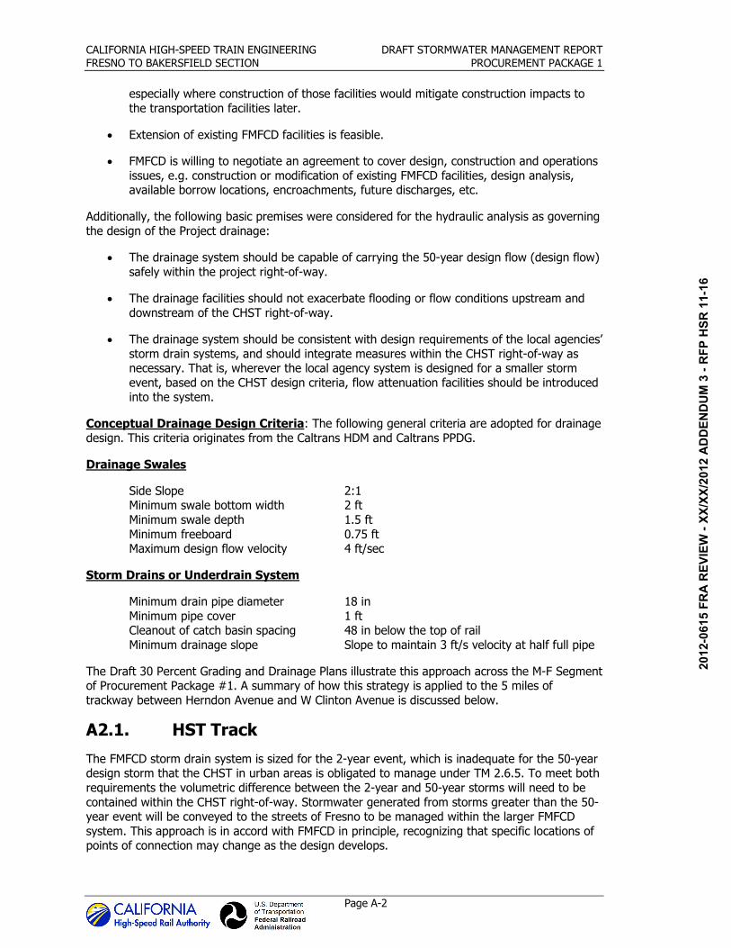
• The drainage system should be capable of carrying the 50-year design flow (design flow)
safely within the project right-of-way.
• The drainage facilities should not exacerbate flooding or flow conditions upstream and
downstream of the CHST right-of-way.
• The drainage system should be consistent with design requirements of the local agencies’
storm drain systems, and should integrate measures within the CHST right-of-way as necessary. That is, wherever the local agency system is designed for a smaller storm
event, based on the CHST design criteria, flow attenuation facilities should be introduced into the system.
Conceptual Drainage Design Criteria: The following general criteria are adopted for drainage
design. This criteria originates from the Caltrans HDM and Caltrans PPDG.
Drainage Swales
Side Slope 2:1 Minimum swale bottom width 2 ft
Minimum swale depth 1.5 ft
Minimum freeboard 0.75 ft Maximum design flow velocity 4 ft/sec
Storm Drains or Underdrain System
Minimum drain pipe diameter 18 in
Minimum pipe cover 1 ft Cleanout of catch basin spacing 48 in below the top of rail
Minimum drainage slope Slope to maintain 3 ft/s velocity at half full pipe
The Draft 30 Percent Grading and Drainage Plans illustrate this approach across the M-F Segment of Procurement Package #1. A summary of how this strategy is applied to the 5 miles of
trackway between Herndon Avenue and W Clinton Avenue is discussed below.
A2.1. HST Track
The FMFCD storm drain system is sized for the 2-year event, which is inadequate for the 50-year design storm that the CHST in urban areas is obligated to manage under TM 2.6.5. To meet both
requirements the volumetric difference between the 2-year and 50-year storms will need to be
contained within the CHST right-of-way. Stormwater generated from storms greater than the 50-year event will be conveyed to the streets of Fresno to be managed within the larger FMFCD
system. This approach is in accord with FMFCD in principle, recognizing that specific locations of points of connection may change as the design develops.
06/2
9/20
12 A
DD
END
UM
3 -
RFP
HSR
11-
16

CALIFORNIA HIGH-SPEED TRAIN ENGINEERING DRAFT STORMWATER MANAGEMENT REPORT
FRESNO TO BAKERSFIELD SECTION PROCUREMENT PACKAGE 1
Page A-3
A2.1.1. At-grade Section (right-of-way 100 feet)
In locations where the right-of-way is wider, drainage swales will be used to collect, convey, and
store stormwater on either side of the alignment (see Figure A-1).
The swales are positioned to collect runoff from the rail embankment and from any areas outside of the right-of-way that drain toward the alignment. The swales run parallel to the alignment
toward connection points with the existing FMFCD storm drain lines and detention basins, and the detention basins to be developed as part of the CHST Project.
In general, the drainage swales will be located along the trackway side, leaving space along the
property line for maintenance road, fence line, and for any utilities associated with the CHST
Project. The longitudinal slope of the swales will follow, in most cases, the existing ground slope.
Based on the preliminary design, most of the drainage swales are designed to have a 2-foot
bottom width and be less than 2 feet deep. The maximum top width is estimated to be about 8
feet.
Figure A-1
At-grade Alignment (Typical Section)
A2.1.2. At-grade Section (right-of-way<60 feet)
In narrow portions (60-foot right-of-way) of the alignment, stormwater will be collected, conveyed, and stored within trench drains located on either side of the alignment (see Figure A-
2). The typical trench drain is 3 feet wide, and of variable depth, lined with a geotextile filter
fabric, with a perforated pipe (of variable diameter) at the bottom of the trench and backfilled with drain rock. Minimum pipe diameter will be 1 foot. The trench drains are positioned to collect
runoff from the rail embankment and any areas outside of the right-of-way that drain toward the alignment. The trench drains run parallel to the alignment toward connection points with the
existing FMFCD storm drain lines.
06/2
9/20
12 A
DD
END
UM
3 -
RFP
HSR
11-
16

CALIFORNIA HIGH-SPEED TRAIN ENGINEERING DRAFT STORMWATER MANAGEMENT REPORT
FRESNO TO BAKERSFIELD SECTION PROCUREMENT PACKAGE 1
Page A-4
Figure A-2
Typical Narrow, At-grade Alignment Section
A2.1.3. Railway Drainage Strategy Summary
Table A-1 summarizes the lengths where each typical section is planned along the CHST alignment, and the potential point of connection of the CHST storm drain system to the existing
FMFCD system.
06/2
9/20
12 A
DD
END
UM
3 -
RFP
HSR
11-
16

CALIFORNIA HIGH-SPEED TRAIN ENGINEERING DRAFT STORMWATER MANAGEMENT REPORT
FRESNO TO BAKERSFIELD SECTION PROCUREMENT PACKAGE 1
Page A-5
Table A-1
Summary of Section Type Along the M-F Procurement Package #1 Alignment
Drainage
Area Location
Drainage Type
Approximate
Point of Connection
Notes
S10535+00 to
S10580+00
Drainage swale North of Station
S10535+00
Connect swales to east (E) FMFCD detention basin on south of Herndon Avenue. The drainage swales will be extended along the CHST right-of-way (either side).
Additional detention is not proposed for this drainage area.
S10580+00 to
S10592+00
Drainage swale S10592+00 Connect swales to (E) storm drain system on the north of Herndon Canal. Onsite earthen detention basin is proposed for this drainage area for runoff attenuation.
S10592+00
to S10617+00
Drainage swale S10617+00
Connect swales to north (N) storm drain system. New storm drain will connect to (E) detention basin on the NE
side of the CHST alignment. The (E) detention basin property is proposed to be acquired by the Authority.
Onsite detention is not proposed.
S10617+00 to
S10648+00
Drainage swale on
SW and storm drain on NE of
right-of-way
S10617+00
Connect swale and storm drain to (E) storm drain system to the SE. Onsite detention is needed at this location.
New storm drain will connect to (E) detention basin on the NE side of the CHST alignment. The (E) detention
basin property is proposed to be acquired by the Authority. Onsite detention system is not proposed.
S10648+00
to S10661+00
Drainage swale on SW and storm
drain on NE side of right-of-way
S10648+00 Connect swale and storm drain to (E) storm drain system.
Onsite detention basins (earthen and concrete) are proposed for this drainage area to attenuate runoff.
S10661+00
to S10701+00
Drainage swale on SW and storm
drain on NE of right-of-way
S10681+00
and
S10701+00
Connect NE storm drain to a (N) storm drain at
S10701+00. The (N) storm drain will ultimately drain to FMFCD detention basin on south of W Ashlan Avenue, NE
of the CHST right-of-way. Connect the SW swale to (E) storm drain system at S10681+00. Onsite detention
basins (earthen) are proposed for swale drainage area to attenuate runoff.
S10701+00 to
S10744+00
storm drain
system S10701+00
Connect the storm drains to a (N) proposed storm drain at S10701+00. The (N) storm drain will ultimately drain to FMFCD detention basin on south of W Ashlan Avenue, NE
of the CHST right-of-way. Onsite detention is not proposed for this drainage area.
S10744+00 to
S10805+00
storm drain system
S10805+00 Connect the storm drains to the Fresno to Bakersfield proposed SD system draining SE.
A2.2. Roadway
The CHST project encompasses multiple roadway re-alignments and improvements throughout the proposed corridor. Local agencies as well as state agencies have standards that deviate from
the general design criteria outlined above for CHST drainage design. The proposed roadway
structure types are summarized in Table A-2.
06/2
9/20
12 A
DD
END
UM
3 -
RFP
HSR
11-
16
CALIFORNIA HIGH-SPEED TRAIN ENGINEERING DRAFT STORMWATER MANAGEMENT REPORT
FRESNO TO BAKERSFIELD SECTION PROCUREMENT PACKAGE 1
Page A-6
Conceptual Drainage Design Criteria: Conceptual design criteria for the proposed roadway
improvements are shown below. This criteria originates from the Caltrans HDM and the Caltrans PPDG.
Drainage Swales
Side Slope 4:1
Minimum swale bottom width 2 ft Minimum swale depth 1.5 ft
Minimum freeboard 0.75 ft Maximum design flow velocity 4 ft/sec
Storm Drains or Under Drains System
Minimum drain pipe diameter 18 in
Minimum under drain pipe diameter 8 in Minimum pipe cover 24 in below the top of roadway grade
The design storm for sizing of proposed basins within Caltrans right-of-way is a 10-year, 24-hour
event. This standard was implemented for local basins and surface streets as well.
Table A-2 Roadway Structure Type
Roadway Design Type
Golden State Boulevard and various Local Street Intersections Re-Aligned, At-Grade
N. Cornelia Ave Re-Aligned, At-Grade
Shaw Avenue, and intersections with N. Jennifer Ave and W. Mission St Retained Earth Overpass
W. Santa Ana Ave Re-Aligned, At-Grade
SR-99 Re-Aligned, At-Grade
SR-99 Interchange @ McKinley Ave Retained Earth Overpass
N Parkway Drive Re-Aligned, At-Grade
Pleasant Ave Re-Aligned, At-Grade
SR-99 Interchange @ Clinton Ave Retained Earth Overpass
Vassar Ave Re-Aligned, At-Grade
N Motel Dr Re-Aligned, At-Grade
N Marks Ave Re-Aligned, At-Grade
Shields Ave Re-Aligned, At-Grade
Valentine Ave Re-Aligned, At-Grade
Dakota Ave Re-Aligned, At-Grade
N Weber Ave Re-Aligned, At-Grade
Ashlan Ave, and intersections with Marty Ave Retained Earth Overpass
SR-99 ramps @ Herndon Ave Re-Aligned, At-Grade
A2.2.1. Watershed Hydrology
The FMFCD has delineated regional watersheds for each of their flood control facilities. To
preserve the serviceability of the FMFCD facilities, FMFCD has requested that the Project approach for stormwater management minimizes diversions across these watershed boundaries.
Where this is not feasible, FMFCD will require flow attenuation to match pre-project peak flows,
as determined and provided by FMFCD. Such mitigation would be costly, and may require
06/2
9/20
12 A
DD
END
UM
3 -
RFP
HSR
11-
16
CALIFORNIA HIGH-SPEED TRAIN ENGINEERING DRAFT STORMWATER MANAGEMENT REPORT
FRESNO TO BAKERSFIELD SECTION PROCUREMENT PACKAGE 1
Page A-7
additional right-of-way. Therefore the stormwater management approach for this project is to
maintain existing flow paths wherever feasible.
To understand the impacts of the proposed drainage design, the watersheds affected by the project site were evaluated to identify drainage diversions from one watershed to another.
Existing watersheds were delineated based on existing flow patterns per the FMFCD master plan. Proposed roadway drainage watersheds were developed based on project conditions. Changes in
land use result in an increase in paved areas that will likely discharge additional runoff to the regional facilities. The regional facilities’ watershed boundaries have remained intact. FMFCD’s
master plan of drainage accounts for future development of the Project site, therefore the
additional flows resulting from the project are not anticipated to create adverse impacts to the serviceability of the FMFCD regional systems.
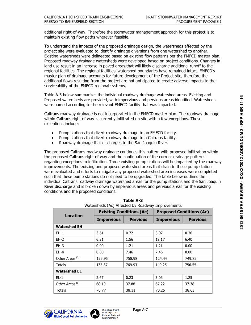
Table A-3 below summarizes the individual roadway drainage watershed areas. Existing and
Proposed watersheds are provided, with impervious and pervious areas identified. Watersheds were named according to the relevant FMFCD facility that was impacted.
Caltrans roadway drainage is not incorporated in the FMFCD master plan. The roadway drainage
within Caltrans right of way is currently infiltrated on site with a few exceptions. These exceptions include:
• Pump stations that divert roadway drainage to an FMFCD facility.
• Pump stations that divert roadway drainage to a Caltrans facility.
• Roadway drainage that discharges to the San Joaquin River.
The proposed Caltrans roadway drainage continues this pattern with proposed infiltration within the proposed Caltrans right of way and the continuation of the current drainage patterns
regarding exceptions to infiltration. Three existing pump stations will be impacted by the roadway improvements. The existing and proposed watershed areas that drain to these pump stations
were evaluated and efforts to mitigate any proposed watershed area increases were completed
such that these pump stations do not need to be upgraded. The table below outlines the individual Caltrans roadway drainage watershed areas for the pump stations and the San Joaquin
River discharge and is broken down by impervious areas and pervious areas for the existing conditions and the proposed conditions.
Table A-3
Watersheds (Ac) Affected by Roadway Improvements
Location Existing Conditions (Ac) Proposed Conditions (Ac)
Impervious Pervious Impervious Pervious
Watershed EH
EH-1 3.61 0.72 3.97 0.30
EH-2 6.31 1.56 12.17 6.40
EH-3 0.00 1.21 1.21 0.00
EH-4 0.00 7.46 7.46 0.00
Other Areas (1) 125.95 758.98 124.44 749.85
Totals 135.87 769.93 149.25 756.55
Watershed EL
EL-1 2.67 0.23 3.03 1.25
Other Areas (1) 68.10 37.88 67.22 37.38
Totals 70.77 38.11 70.25 38.63
06/2
9/20
12 A
DD
END
UM
3 -
RFP
HSR
11-
16

CALIFORNIA HIGH-SPEED TRAIN ENGINEERING DRAFT STORMWATER MANAGEMENT REPORT
FRESNO TO BAKERSFIELD SECTION PROCUREMENT PACKAGE 1
Page A-8
Location Existing Conditions (Ac) Proposed Conditions (Ac)
Impervious Pervious Impervious Pervious
Watershed AH1
AH1-1 4.96 1.41 6.16 3.18
AH1-2 3.81 0.85 5.25 2.79
AH1-3 5.00 0.00 8.45 0.06
AH1-4 2.48 0.00 3.47 0.00
Other Areas (1) 338.55 288.03 332.69 283.04
Totals 354.80 290.29 356.02 289.07
Watershed AK
AK-1 4.42 0.00 4.63 0.30
AK-2 0.28 0.00 0.66 0.20
AK-3 0.43 0.00 0.38 0.00
AK-11 4.42 0.00 4.63 0.30
AK-12 0.28 0.00 0.66 0.20
Other Areas (1) 32.61 26.55 32.10 26.14
Totals 39.82 26.55 39.73 26.64
Watershed EE
EE-1 2.20 0.00 2.51 0.00
Other Areas (1) 703.65 1646.97 703.55 1646.75
Totals 705.85 1646.97 706.06 1646.76
Watershed XX
XX-1 2.39 0.00 2.11 0.00
Other Areas (1) 216.92 146.21 217.09 146.32
Totals 219.31 146.21 219.20 146.32
Watershed AG
AG-1 4.10 0.00 4.20 0.00
Other Areas (1) 214.99 511.22 214.96 511.15
Totals 219.09 511.22 219.16 511.15
San Joaquin River
H1-1 0.97 1.60 1.75 2.23
H1-2 1.64 2.98 0.60 0.30 (1) These watershed areas are outside the Project limits.
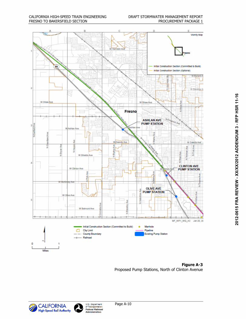
A2.2.2. Pump Stations
Olive Avenue Pump Station. The Olive Ave pump station is located beneath the Olive Ave
overcrossing. A comparison of the pre-project and post-project watersheds is presented in Table A-4 below. The tributary area draining towards the Olive Ave pump station has been reduced by
approximately 0.19 ac. This reduction is a result of a proposed infiltration basin near the upstream portion of the Olive Ave pump station watershed. Proposed drainage inlets divert
roadway drainage toward “IFB 101L” prior to reaching the Olive Ave pump station. This was done
06/2
9/20
12 A
DD
END
UM
3 -
RFP
HSR
11-
16

CALIFORNIA HIGH-SPEED TRAIN ENGINEERING DRAFT STORMWATER MANAGEMENT REPORT
FRESNO TO BAKERSFIELD SECTION PROCUREMENT PACKAGE 1
Page A-9
to mitigate the additional impervious area created with the proposed auxiliary lane along the SR-
99 alignment. As a result of the reduction of tributary area to the Olive Avenue Pump Station, without physical modifications which would affect the structure, replacement of the pump station
is not required due to the SR 99 improvements.
Ashlan Avenue Pump Station. The Ashlan Ave pump station is located beneath the Ashlan Ave overpass over the SR-99 alignment. A comparison of the pre-project and post-project
watersheds is presented in Table A-4 below. The tributary area draining towards the Ashlan Ave Pump Station has been reduced by approximately 0.08 ac. This reduction is a result of the re-
alignment of SR-99 and the re-location of drainage inlets near the top of the Ashlan Ave pump
station watershed. These proposed drainage inlets divert roadway drainage toward the proposed infiltration basin “IFB 233L”. As a result of the reduction of tributary area to the Ashlan Avenue
Pump Station, without physical modifications which would affect the structure, replacement of the pump station is not required due to the SR 99 improvements.
Clinton Avenue Pump Station. The Clinton Ave pump station is located beneath the SR-99
alignment on the SB SR-99 off ramp to Motel Dr. The portion of roadway that houses this pump station is proposed to be left in place. Further upstream within the pump station watershed there
will be significant alterations in the roadway geometry which will affect the post-project
watershed. For example, the SB off ramp will be re-aligned horizontally and vertically.
A comparison of the pre-project and post-project watersheds is presented in Table A-4 below. The tributary area draining towards the Clinton Ave pump station has been reduced by
approximately 1.01 ac. This reduction is a result of the modifications to the SB SR 99 off ramp and other roadway modifications. Those roadway modifications have also resulted in a local
diversion of some of the former pump station watershed to IFB 132R. As a result of the reduction of tributary area to the Clinton Avenue Pump Station, without physical modifications which would
affect the structure, replacement of the pump station is not required due to the SR 99
improvements. Figure A-3 shows the locations of the proposed pump stations.
Table A-4 Pump Station Watersheds
Location Existing Conditions Proposed Conditions
Impervious Pervious Impervious Pervious
Olive Pump Station
95R 1.70 0.00 1.51 0.00
Ashlan Pump Station
250L 3.02 0.00 2.94 0.00
Clinton Pump Station
132R 1.48 3.72 1.47 2.72
Infiltration Basins. Proposed drainage for the new Caltrans right-of-way will provide retention
of runoff similarly to the existing condition. Infiltration basins are proposed to capture two 10-year storms, in accordance with the Caltrans’ standard hydraulic design criteria for the Central
Region Districts (5, 6, & 10). They will also provide stormwater treatment and are proposed as treatment BMPs. Surface streets that had roadway improvements with drainage that did not
discharge into a FMFCD facility also had proposed infiltration basins for final discharge. Table A-5
below summarizes the watershed areas tributary to each basin.
06/2
9/20
12 A
DD
END
UM
3 -
RFP
HSR
11-
16
CALIFORNIA HIGH-SPEED TRAIN ENGINEERING DRAFT STORMWATER MANAGEMENT REPORT
FRESNO TO BAKERSFIELD SECTION PROCUREMENT PACKAGE 1
Page A-10
Figure A-3 Proposed Pump Stations, North of Clinton Avenue
06/2
9/20
12 A
DD
END
UM
3 -
RFP
HSR
11-
16

CALIFORNIA HIGH-SPEED TRAIN ENGINEERING DRAFT STORMWATER MANAGEMENT REPORT
FRESNO TO BAKERSFIELD SECTION PROCUREMENT PACKAGE 1
Page A-11
Table A-5
Proposed Caltrans Infiltration Basins
Watershed Proposed Conditions
Impervious Pervious
101L 2.08 1.83
115L 4.02 3.27
130L 0.98 0.96
132R 6.10 8.89
141L 0.57 1.97
157L 17.30 6.56
205L 10.24 6.11
208L 1.08 0.47
213L 0.80 0.39
233L 0.92 2.62
239L 1.95 2.49
FMFCD Basin
208L 1.08 0.47
130L 0.98 0.96
213L 0.80 0.39
06/2
9/20
12 A
DD
END
UM
3 -
RFP
HSR
11-
16
06/2
9/20
12 A
DD
END
UM
3 -
RFP
HSR
11-
16

APPENDIX B Summary of Stormwater Management Strategy
(Fresno to Bakersfield Section)
06/2
9/20
12 A
DD
END
UM
3 -
RFP
HSR
11-
16

06/2
9/20
12 A
DD
END
UM
3 -
RFP
HSR
11-
16
CALIFORNIA HIGH-SPEED TRAIN ENGINEERING DRAFT STORMWATER MANAGEMENT REPORT
FRESNO TO BAKERSFIELD SECTION PROCUREMENT PACKAGE 1
Page B-1
B1. Existing FMFCD System
The general topography around the HST right-of-way is gently sloping northeast-southwest. The stormwater run-on and run-off from the right-of-way sheet-flows into the adjacent properties.
Further, the runoff from these areas finds its way to the local Fresno Metropolitan Flood Control District (FMFCD) storm drain system and infiltration and/or detention basins (hereafter referred
to as basins). In addition to providing infiltration and storage, the basins serve as best
management practices (BMPs) for treating the FMFCD’s stormwater. Several private developments along the alignment also have owner-operated detention and infiltration facilities in
areas where FMFCD facilities have not yet been built.
In the southern portion of Procurement Package #1, between W Clinton Avenue and just south of E American Avenue, the general approach is to use the HST right of way to collect and convey
stormwater to the existing FMFCD stormwater collection system. As discussed above the existing
FMFCD system consists of a number of discrete watersheds across the entire Procurement Package #1 area. The FMFCD pipes throughout Fresno are generally sized to convey the 2-year
storm event to basins. When Fresno experiences an event larger than the 2-year storm, stormwater collects in the streets until the system clears. The basins are sized to manage larger
storm events and are often connected in series, with storm volumes managed between basins. When stormwater volumes exceed the basin capacities, water is pumped to one of the many
canals that traverse Fresno. The FMFCD watersheds are provided in Figure 1-2 with proposed
points of CHST connection to the FMFCD system identified in the proposed preliminary design drainage and grading plans.
B2. Alignment Drainage Strategies
Grading and drainage for the project improvements were discussed with FMFCD on September
14, 2011. Preliminary design concepts were presented and the general approach for stormwater
management, including treatment, was discussed. Based on that meeting general design principles were agreed for drainage within the FMFCD jurisdiction. While the 30% design has not
been reviewed by the City or FMFCD, these principles became the basis of the stormwater management approach. They include the following:
• The FMFCD has performed extensive hydrologic and hydraulic analysis of their flood
control system. The Project must preserve the existing flow patterns as much as
possible. Where this is not feasible, coordination with FMFCD will be required and
mitigation of peak flows will be mandatory.
• The FMFCD MS4 Permit allows discharges from developments directly to the FMFCD
regional flood control system.
• While FMFCD encourages direct discharges to their flood control system, runoff from HST
storm drains should be distributed purposefully to minimize diversions across watershed
boundaries.
• For direct connections to the FMFCD storm drain system, peak flows must be mitigated
to allowable values (provided by FMFCD). For direct connections to detention basins, no peak attenuation is required. For sheet flows off the roadways, track, no detention is
required.
• In some instances the HST may desire to increase the size of proposed FMFCD storm
drainage pipelines and/or construct parallel storm drainage specifically for HST needs to
an FMFCD stormwater management basin. Increasing the diameter of planned facilities could convey an increased flow generated by the HST and this option should be
06/2
9/20
12 A
DD
END
UM
3 -
RFP
HSR
11-
16
CALIFORNIA HIGH-SPEED TRAIN ENGINEERING DRAFT STORMWATER MANAGEMENT REPORT
FRESNO TO BAKERSFIELD SECTION PROCUREMENT PACKAGE 1
Page B-2
considered in the design of the stormwater conveyance system. The cost for such
revisions to the Master Plan would be borne by the HST and not be eligible for fee credit.
• The construction of an overpass at W McKinley Avenue adjoins FMFCD Basin “EE”. The HST must not allow any runoff from the HST right-of-way to surface flow into the basins
as it would cause severe and unacceptable erosion.
• FMFCD cannot accept a reduction in the capacity of basin “RR2” at Belmont Avenue.
FMFCD recommends expansion of the basin beneath Belmont Avenue and expansion into
what is currently the Belmont Circle. FMFCD will need access beneath Belmont Avenue so that maintenance does not require external travel between the two sides of Belmont
Avenue. Basin side slope must be no steeper than 4:1. No additional HST drainage will be accepted into this basin. HST shall be required to provide access and maintenance
roads that will meet all weather access requirements for operations and maintenance of
Basin “RR2” for any proposed mitigation.
• Caltrans’ runoff is not incorporated into the FMFCD master plan—they currently infiltrate
their runoff within the Caltrans right-of-way.
• Stormwater runoff discharges to FID facilities are not permitted.
• Where it is feasible, FMFCD encourages portions of the planned FMFCD storm drains
which are planned to cross the HST right-of-way to be constructed as part of this project, especially where construction of those facilities would mitigate construction impacts to
the transportation facilities later.
• Extension of existing FMFCD facilities is feasible.
• FMFCD is willing to negotiate an agreement to cover design, construction and operations
issues, e.g. construction or modification of existing FMFCD facilities, design analysis,
available borrow locations, encroachments, future discharges, etc.
Additionally, the following basic premises were considered for the hydraulic analysis as governing the design of the Project drainage:
• The drainage system should be capable of attenuating and conveying the 50-year design
flow (design flow) safely within the project right-of-way.
• The drainage facilities should not exacerbate flooding or flow conditions upstream and
downstream of the CHST right-of-way.
• The drainage system should be consistent with design requirements of the local agencies’
storm drain systems, and should integrate measures within the CHST right-of-way as necessary. That is, wherever the local agency system is designed for a smaller storm
event, based on the CHST design criteria, flow attenuation facilities should be introduced
into the system.
The proposed preliminary design grading and drainage plans illustrate this approach across the F-B JV portion of Procurement Package 1. A summary of how this strategy is applied across five
typical alignment types (Constrained, At-Grade Section: 2-Track; Constrained, At-Grade Section: 4-Track or More; Railway Grade Separation: Below Grade; Railway Grade Separation: Above
Grade; and Unconstrained, At-Grade Section), is provided below.
06/2
9/20
12 A
DD
END
UM
3 -
RFP
HSR
11-
16

CALIFORNIA HIGH-SPEED TRAIN ENGINEERING DRAFT STORMWATER MANAGEMENT REPORT
FRESNO TO BAKERSFIELD SECTION PROCUREMENT PACKAGE 1
Page B-3
B2.1. Constrained, At-Grade Section: 2-Track (right-
of-way<100 ft)
In narrow portions of the alignment (right-of-way <100 feet) stormwater will be collected,
stored, and conveyed within trench drains or swales located on either side of the alignment (see Figures B-1). The typical trench drain is three feet wide, and of variable depth, lined with a
geotextile filter fabric, with a perforated pipe (of variable diameter) at the bottom of the trench. The trench drain is backfilled with drain rock. The trench drains are positioned to collect runoff
from the rail embankment and any areas outside of the right of way that drain towards the alignment. The trench drains run parallel to the alignment towards intermittent connection points
with the existing FMFCD storm drain lines.
Figure B-1
Typical Constrained, At-grade Alignment: 2-Track Section
B2.2. Constrained, At-Grade Section: 4-Track or More
Portions of the alignment that are stations or approaching stations up to six parallel tracks will be required to collect and convey stormwater with trench drains placed strategically across the
section (see Figure B-2). The typical trench drain is three feet wide, and of variable depth, lined with a geotextile filter fabric, with a perforated pipe (of variable diameter) at the bottom of the
trench. The trench drain is backfilled with drain rock. The trench drains are positioned to collect
runoff from the rail embankment and any areas outside of the right of way that drain towards the alignment. The trench drains run parallel to the alignment towards intermittent connection points
with the existing FMFCD storm drain lines.
06/2
9/20
12 A
DD
END
UM
3 -
RFP
HSR
11-
16

CALIFORNIA HIGH-SPEED TRAIN ENGINEERING DRAFT STORMWATER MANAGEMENT REPORT
FRESNO TO BAKERSFIELD SECTION PROCUREMENT PACKAGE 1
Page B-4
Figure B-2
Typical Constrained, At-grade Alignment: 4-Track or More Section
B2.3. Railway Grade Separation: Below Grade
Below grade separation sections typically have three drains that run parallel to the alignment
(see Figure B-3). Two drains are at-grade on either side of the grade separation to collect runoff from any areas outside of the right of way that drain towards the alignment. These at-grade
drains are either concrete lined channels of variable depths or earthen swales. The at-grade drainage lines collect and convey stormwater flowing towards the alignment from outside the
HST right-of-way to intermittent FMFCD points of connection. Stormwater volumes in excess of
the 2-year stormwater event will be attenuated within the at-grade drainage facilities. The primary function of the at-grade drainage lines is to avoid ponding next to the Fresno grade
separation walls and to provide a route for surface water that would previously have flowed overland across the HST right-of-way. It is recommended that UPRR be consulted on drainage
issues in this area.
Drains within the grade separation are located between the rails and serve to collect and convey stormwater to the low point of the trench. At the low point of the grade separation, the
stormwater is diverted into a wet well and then pumped to an at-grade detention basin. The
detention basin is sized to contain the 50-year storm event volume collected from the grade separation and will be pumped to the existing FMFCD storm drain facilities at the 2-year event
flow rate.
06/2
9/20
12 A
DD
END
UM
3 -
RFP
HSR
11-
16

CALIFORNIA HIGH-SPEED TRAIN ENGINEERING DRAFT STORMWATER MANAGEMENT REPORT
FRESNO TO BAKERSFIELD SECTION PROCUREMENT PACKAGE 1
Page B-5
Figure B-3
Typical Rail Grade Separation: Below Grade Section
B2.4. Railway Grade Separation: Above Grade
Elevated sections drain water to channels on either the outside edges of the viaduct (see Figure B-4) or a single central drain between the rails. Stormwater is directed into drain inlets located
intermittently along the channel and piped through down spouts at the viaducts structural columns to grade. At-grade, stormwater is directed into a trench drain or swale that runs
beneath and parallel to the rail alignment. The trench drain/swale conveys water towards points
of connection with the existing FMFCD storm drain lines, while storing the volumetric difference between the 2-year event and 50-year event.
Variations to this approach will occur where the elevated section is a steel truss. In these
sections, stormwater will be collected and conveyed through pipes in the structure towards a drain inlet located at the low point of the steel truss. The stormwater will then be conveyed down
to grade and into trench drains/swales through a similar approach as described above.
06/2
9/20
12 A
DD
END
UM
3 -
RFP
HSR
11-
16

CALIFORNIA HIGH-SPEED TRAIN ENGINEERING DRAFT STORMWATER MANAGEMENT REPORT
FRESNO TO BAKERSFIELD SECTION PROCUREMENT PACKAGE 1
Page B-6
Figure B-4
Typical Rail Grade Separation: Above Grade Section
06/2
9/20
12 A
DD
END
UM
3 -
RFP
HSR
11-
16
CALIFORNIA HIGH-SPEED TRAIN ENGINEERING DRAFT STORMWATER MANAGEMENT REPORT
FRESNO TO BAKERSFIELD SECTION PROCUREMENT PACKAGE 1
Page B-7
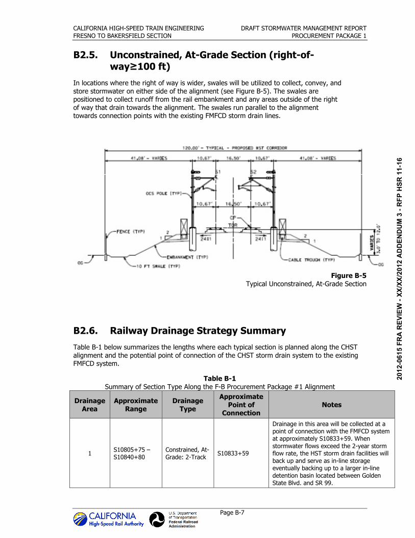
B2.5. Unconstrained, At-Grade Section (right-of-
way≥100 ft)
In locations where the right of way is wider, swales will be utilized to collect, convey, and
store stormwater on either side of the alignment (see Figure B-5). The swales are positioned to collect runoff from the rail embankment and any areas outside of the right
of way that drain towards the alignment. The swales run parallel to the alignment towards connection points with the existing FMFCD storm drain lines.
Figure B-5
Typical Unconstrained, At-Grade Section
B2.6. Railway Drainage Strategy Summary
Table B-1 below summarizes the lengths where each typical section is planned along the CHST
alignment and the potential point of connection of the CHST storm drain system to the existing FMFCD system.
Table B-1
Summary of Section Type Along the F-B Procurement Package #1 Alignment
Drainage Area
Approximate Range
Drainage Type
Approximate
Point of Connection
Notes
1 S10805+75 –
S10840+80
Constrained, At-
Grade: 2-Track S10833+59
Drainage in this area will be collected at a point of connection with the FMFCD system at approximately S10833+59. When
stormwater flows exceed the 2-year storm flow rate, the HST storm drain facilities will
back up and serve as in-line storage eventually backing up to a larger in-line
detention basin located between Golden
State Blvd. and SR 99.
06/2
9/20
12 A
DD
END
UM
3 -
RFP
HSR
11-
16

CALIFORNIA HIGH-SPEED TRAIN ENGINEERING DRAFT STORMWATER MANAGEMENT REPORT
FRESNO TO BAKERSFIELD SECTION PROCUREMENT PACKAGE 1
Page B-8
Drainage
Area
Approximate
Range
Drainage
Type
Approximate Point of
Connection
Notes
2 S10841+58–
S10853+68
Constrained, At-
Grade: 2-Track S10846+96
3 S10854+68– S10865+40
Constrained, At-Grade: 2-Track
S10861+05
4 S10866+50 – S10884+00
Constrained, At-Grade: 2-Track
S10875+54
5 S10885+00 – S10975+00
Below Grade S10935+00
The at-grade drainage points of connection to the FMFCD system are located
approximately at:
S10897+56
S10948+55
S10953+83
S10962+64
S10972+50
The low point of the below grade alignment
is at approximately S10926+93. From this location the stormwater is pumped up to a
detention basin and then discharged to a FMFCD point of connection at
approximately S1093+00.
6 S10976+00 – S10991+65
Constrained, At-Grade: 4-Track
or More
S10986+75
7 S10992+81 – S11030+00
Constrained, At-Grade: 4-Track or More
S11011+17
Temporary in-line detention basins are provided in the station area to manage
drainage storm flows in excess of the 2-year storm flow rate for the station area
prior to station construction.
8 S11030+00 – S11035+00
Unconstrained, At-Grade
S11037+00
9 S11035+00 – S11052+00
Unconstrained, At-Grade
S11050+00
10 S11052+00 – S11069+40
Unconstrained, At-Grade
S11060+75
11 S11069+40 –
S11140+00 Below Grade S11119+50
The at-grade drainage points of connection to the FMFCD system are located
approximately at:
S11072+00
S11086+00
S11122+00
S11134+00
The low point of the below grade alignment is at approximately S11119+50. From this
location the stormwater is pumped up to a detention basin and then discharged to a
FMFCD point of connection at approximately S11134+00.
06/2
9/20
12 A
DD
END
UM
3 -
RFP
HSR
11-
16

CALIFORNIA HIGH-SPEED TRAIN ENGINEERING DRAFT STORMWATER MANAGEMENT REPORT
FRESNO TO BAKERSFIELD SECTION PROCUREMENT PACKAGE 1
Page B-9
Drainage
Area
Approximate
Range
Drainage
Type
Approximate Point of
Connection
Notes
12 S11140+00 – S11230+00
Above Grade
The at-grade drainage points of connection
to the FMFCD system are located approximately at:
S11155+50
S11165+50
S11174+50
S11186+50
S11210+50
S11217+50
S11224+00
S11236+50
Points of connection to the existing
Caltrans detention basin at ST 99 are located approximately at:
S11200+00
S11201+00
13 S11230+00 – S11236+50
At-Grade S11236+50
14 S11236+50 – S11263+75
At-Grade S11263+75
15 S11263+75 – S11276+95
At-Grade S11276+95
16 S11276+95 – S11300+00
At-Grade S11290+00
B3. Roadway
The CHST project encompasses multiple roadway re-alignments and improvements throughout
the proposed corridor.
The FMFCD has delineated regional watersheds for each of their flood control facilities. To preserve the serviceability of the FMFCD facilities, FMFCD has requested that the Project
approach for stormwater management minimizes diversions across these watershed boundaries. Where this is not feasible, FMFCD will require flow attenuation to match pre-project peak flows,
as determined and provided by FMFCD. Such mitigations would be costly, and may require additional right-of-way. Therefore the stormwater management approach for this project is to
maintain existing flow paths wherever feasible.
To understand the impacts of the proposed drainage design, the watersheds affected by the
project site were evaluated to identify drainage diversions from one watershed to another. Existing watersheds were delineated based on existing flow patterns per the FMFCD master plan.
Proposed roadway drainage watersheds were developed based on project conditions. Changes in land use result in an increase in paved areas that will likely discharge additional runoff to the
regional facilities. FMFCD’s master plan of drainage accounts for future development of the Project site, therefore the additional flows resulting from the project are not anticipated to create
adverse impacts to the serviceability of the FMFCD regional systems.
06/2
9/20
12 A
DD
END
UM
3 -
RFP
HSR
11-
16

CALIFORNIA HIGH-SPEED TRAIN ENGINEERING DRAFT STORMWATER MANAGEMENT REPORT
FRESNO TO BAKERSFIELD SECTION PROCUREMENT PACKAGE 1
Page B-10
Drainage for new or realigned roadways resulting from this project is being designed to be
integrated into the existing FMFCD system. Generally, there are three types of roadway design that are being completed for this project and each has a slightly different approach for managing
stormwater. Each of the three stormwater management strategies is discussed below, while Table B-2 provides a summary of the drainage strategy applied at each proposed roadway
improvement.
B3.1. At-Grade Streets
New or realigned streets will be integrated in to the FMFCD stormwater system. Drain inlets will
be replaced or relocated to match the FMFCD requirements and will connect to new or relocated FMFCD stormwater pipes. The new drain inlets and pipes resulting from the new or realigned
streets will be sized to collect and convey the 2-year storm flow, unless agreed otherwise with FMFCD.
A number of existing street crossings will be closed as a result of this project. As such, existing
surface drainage patterns that utilize streets must be carefully reviewed with an aim of maintaining existing drainage patterns with cross drains or other approved conveyance systems,
including provisions for any major storm flows across the HST. The change in street
improvements in the vicinity of the HST must be similarly mitigated with respect to drainage impacts. To assist HST, FMFCD has identified the following roadways from Clinton Avenue south,
where major storm surface flows must cross the HST alignment:
• McKinley Avenue
• Divisadero Street
• S Van Ness Avenue
• S East Avenue
• S Orange Avenue
• E Central Avenue
• E Malaga Avenue
B3.2. Roadway Overpasses
There are numerous roadway relocations required as part of this project that will divert existing
at-grade roadways over the proposed rail alignment. These grade separations take several different forms depending on the space constraints, but all bridge over the rail alignment with a
concrete bridge span. Stormwater will be collected in curb and gutters at the outside edges of the grade separation structures which will convey stormwater towards drain inlets at the at-grade
base of the structure. The new drain inlets and pipes resulting from the new or realigned grade
separated streets will be sized to collect and convey the 2-year storm flow.
B3.3. Roadway Underpasses
Where roadways are proposed to be relocated under the HST alignment stormwater will be collected in curb and gutters at the outside edges of the underpass which will convey stormwater
towards intermittent drain inlets as the water flows to the low point. The drain inlets will convey stormwater to pipes and eventually into a wet well. From the wet well, stormwater will be
pumped to an at-grade storage area designed to contain the 50-year storm event volume. The
storage area will discharge, utilizing gravity, to the existing FMFCD storm drain lines at the 2-year event flow rate.
06/2
9/20
12 A
DD
END
UM
3 -
RFP
HSR
11-
16

CALIFORNIA HIGH-SPEED TRAIN ENGINEERING DRAFT STORMWATER MANAGEMENT REPORT
FRESNO TO BAKERSFIELD SECTION PROCUREMENT PACKAGE 1
Page B-11
Table B-2
Roadway Structure Type
Roadway Design Type
W McKinley Avenue Retained Earth Overpass
McKinley Avenue Connector New, At-Grade
N Weber Avenue Re-Aligned, At-Grade
N West Avenue Re-Aligned, At-Grade
N Golden State Blvd. Re-Aligned, At-Grade
W Oliver Avenue Retained Earth Overpass
W Belmont Avenue Retained Earth Overpass
N H Street/N Weber Avenue Re-Aligned, At-Grade
Wesley Avenue Re-Aligned, At-Grade
N Thorne Avenue Re-Aligned, At-Grade
Stanislaus Street Retained Earth Overpass
Fresno Street To be completed by others
G Street Re-aligned, Overpass
Tulare Street Underpass
Ventura Street Underpass
E Church Avenue Retained Earth Overpass
E Central Avenue Retained Earth Overpass
E American Avenue Embanked Earth Overpass
06/2
9/20
12 A
DD
END
UM
3 -
RFP
HSR
11-
16