
Reproduction Quality Notice · reproduction quality notice ... fowler flaps submitted by...
30
Reproduction Quality Notice This document is part of the Air Technical Index [ATI] collection. The ATI collection is over 50 years old and was imaged from roll film. The collection has deteriorated over time and is in poor condition. DTIC has reproduced the best available copy utilizing the most current imaging technology. ATI documents that are partially legible have been included in the DTIC collection due to their historical value. If you are dissatisfied with this document, please feel free to contact our Directorate of User Services at [703] 767-9066/9068 or DSN 427-9066/9068. Do Not Return This Document To DTIC
Transcript of Reproduction Quality Notice · reproduction quality notice ... fowler flaps submitted by...

Reproduction Quality Notice
This document is part of the Air Technical Index [ATI] collection. The ATI collection is over 50 years old and was imaged from roll film. The collection has deteriorated over time and is in poor condition. DTIC has reproduced the best available copy utilizing the most current imaging technology. ATI documents that are partially legible have been included in the DTIC collection due to their historical value.
If you are dissatisfied with this document, please feel free to contact our Directorate of User Services at [703] 767-9066/9068 or DSN 427-9066/9068.
Do Not Return This Document To DTIC
i ,;• >; t-'f •.:.*" -• •«
/' \\v'
Reproduced by
AIR DOCUMENTS DIVISION
".'f»-ipl^-j%j
•jr-v •t
IS ABSOLVED 4
FROM ANY UTIGATION WHICH MAY
>» <*>
ENSUE PROM THE CONTRACTORS IN-
Abbott, tern !• r, 1. R.
Asrodynaales (2) Wings and Airfoil. (6)
Airfoils - Drag (0*KX>)» Airfolla • lift (08210)| total* • Mad t«ml tasting (6AA09.A)
20820
RR-1677
lift and drag tssts of thraa airfoil aodala with foalar flap* aubalttad ay
Rational Advisory Coaalttse for Awranautios, Maahington, D. C.
0.3. Uaalaas. Dao'U 23 photos, diagr, graflha
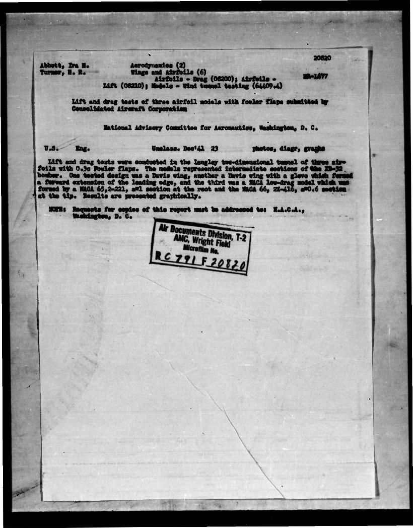
Lift and drag taata waro eonduotad la tha Xanglay two-dl—nstonal tuanal of folia with 0.3o ftowlar flaps. Tha aodala raprasantad lataraodlata aattloni of boahor. Ooa toatad daalgn aaa a Bawls wing, aoothar a Oavia wing with a glows whlah a forward sxtoasion of tha laadlag odga, aad tha third aaa a RICA low-drag aodal whlah ajj foraad by a RASA 65,2-221, aol saotlon at tha root and tha KACA 66, 2X-416, aP0.6 saotloa at tha tip* Results are praaontsd graphically.
for oopdoa of this roport oast ho addrsassd tot R.A.C.A., i, D. C.
( ,
J »•
ATI .%3QS&o i
MB Dec. 13hl
NATIONAL ADVISORY COMMITTEE FOR AERONAUTICS
WARTIME REPORT ORIGINALLY ISSUED December J.9'11 as Memorandum Report
LIFT AND DRAG TESTS OF THREE AIRF0I1 MODELS WITH
FOWLER FLAPS SUBMITTED BY CONSOLIDATED
AIRCRAFT CORPORATION
By Ira. H. Abbott and Harold R. Turner, Jr.
Langley Memorial Aeronautical Laboratory Langley Field, Va.
HACA WASHINGTON
NACA WARTIME REPORTS are reprints .>f papers originally issued to provide rapid distribution of advance research results to an authorized group requiring them for the war effort. They were pre- viously held under a security status but are now unclassified. Some of these reports were not tech- nically edited. All have been reproduced without change In order to expedite general distribution.
L - 677
NATIONAL ADVISORY COMMITTEE FOR AERONAUTICS
MEMORANDUM REPORT
for
Materiel Division, Army Air Corps
LIFT AND DRA3 TESTS OF THREE AIRFOIL MODELS WITH
FOOLER FLAPS SUBMITTED BY CONSOLIDATED
AIRCRAFT CORPORATION
By Ira H. Abbott and Harold R. Turner, Jr.
INTRODUCTION
Lift and drag tests were made In the Langley two- dimensional tunnel of three airfoil models submitted by the Consolidated Aircraft Corporation. The models represented Intermediate sections on alternative wings of the XB-JS2 airplane and were equipped with 0.3c Fowler flaps.
The three alternative wings, sections of which were represented by the models, were as follows:
1. A Davis wing.
2. A wing obtained by adding a glove to the Davis wing with a forward extension of the leading edge. The resulting shape approximated a low-drag type section over the forward portion while retaining the shape of the Davis wing over the rear portion. Such a glove, If applied over existing structure, would increase the chord of the wing and reduce the relative thickness. The model, however, was of the same chord and thickness as the other models. This section was designated C.A.C. by the Consolidated Aircraft Corporation and is so designated throughout this report.
3. A wing with the NACA 65,2-221, a = 1 section at the root and the NACA 66, 2X-I4.I6, a = 0.6 section at the tip. This model is designated the NACA low-drag model.
The models were tested with various flap deflections up to I4.O0. Most of the tests were made at a value of the Reynolds number of about 6,000.000. Additional flap
I
- 2 -
positions wera tested on the model representing the NACA low-drag wing to improve the drng of the suction in the cruising and climbing rangos of lift coefficients and to obtain improved maximum lift coefficients.
DESCRIPTION OF H0D3LS
The models were constructed by the Consolidated Aircraft Corporation and wore of 24-inch chord and approximately 18 percent thick. The models wore equipped with pressure-distribution orifices.
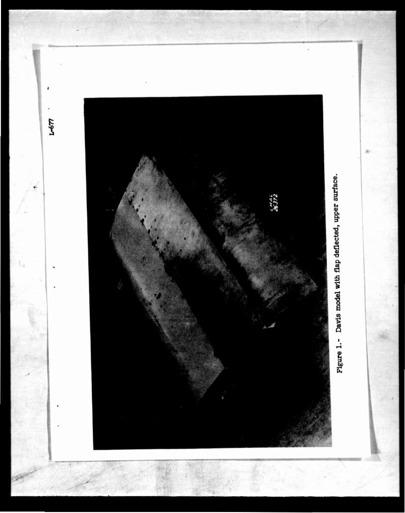
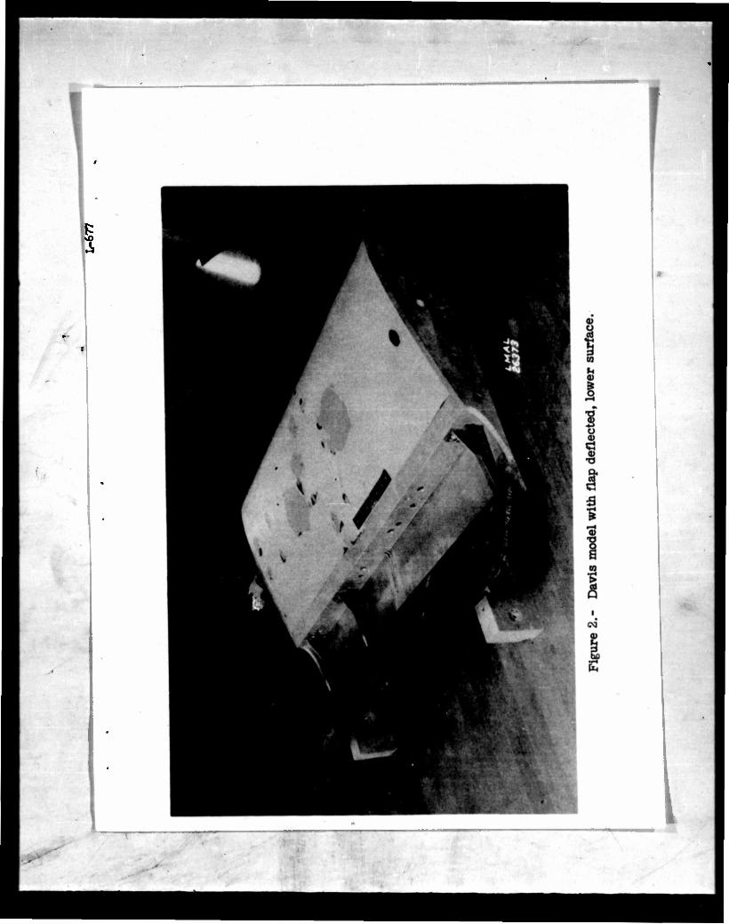
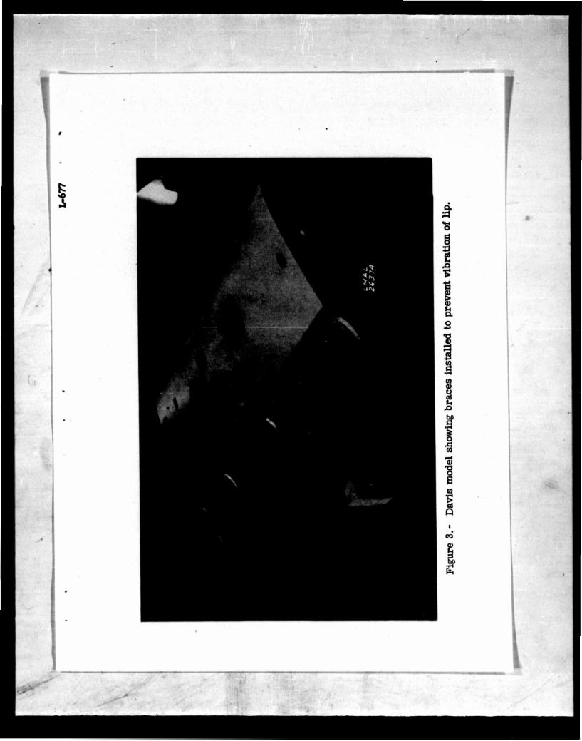
The models were constructed of wood and metal. The greater part of the main airfoil surface was finished with paint. The metal flaps wore attached with four brackets, a separate set of brackets being provided for each flap defloction. For those tests, onu flap bracket of each set was not used to allow a sufficient spanwiso space free of brackets to permit drag measurements to be made. As received, the tubes from the pressure orifices in the flaps projected from the flap loading edges in such a manner as to interfere with the flow through the 3lot. These tubes wore removed and will be replaced later as required for pressure-distribution measurements. The appearanco of tho modols with these tubes removed and with throe flap brackets in place as testod is shown in figur«3 1 and 2. During the first tests on the Davis model, considerable trouble was experienced by vibration of tho plate forming the lip of tho airfoil. Bracks to stiffen this plate were accordingly installed on all models as shown in figure 3.
TEST METHODS
The modols were tested in tho Langloy two-dimensional tunnol, which is characterized by an extremely low air- stream turbulence. Tho models extended from wall to wall of the rectangular tost soction. Lift data wore obtained by means of a manometer arrangement which integrated the lift reaction of tho model on the floor and ceiling of tho tunnel test section. Comparison of such readings with lifts obtained from model pressure distributions has shown the method to bo reliable. Drag data worts obtained by tho wake-survey nnthod, using an integrating manometer.
- 5 -
l
Host of the teats were made at tunnel pressures of either 3 or h atmospheres. Care was taken to avoid airspeeds which might involve compressibility effects at high lift coefficients.
The values of th8 section lift coefficients should be corrected by the following enuations, which were not applied when the data were computed:
Davis airfoil: cl(corrected) = 0.978^ + 0.021^
C.A.C. airfoil: c,^^^ = 0.9930! + 0.013^
NACA low-drag airfoil:
^(corrected) = °'"2cl + 0'015c*b
Is the section lift coefficient at a = 2° where e j for both the Davis and the C.A.C. airfoil. For the
ig ai olent at <x = 1°. NACA low-drag airfoil, olh is the section lift coeffl*
RESULTS AND DISCUSSION
Davis Model
.-***-:
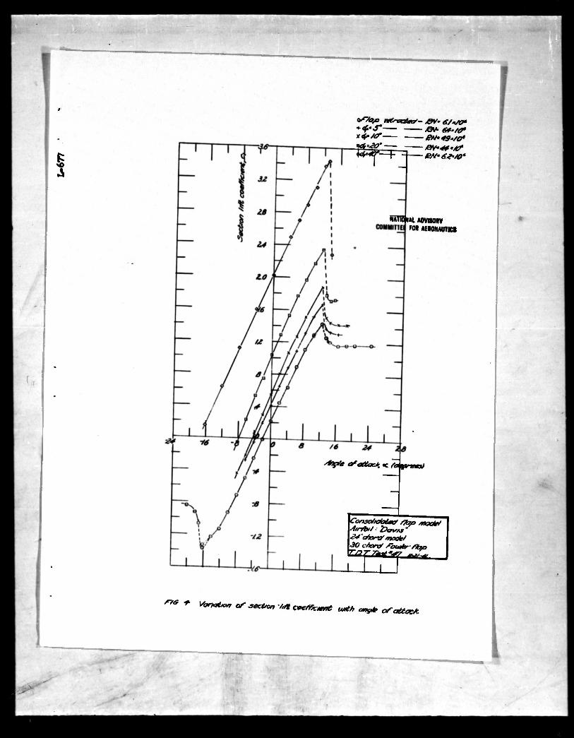
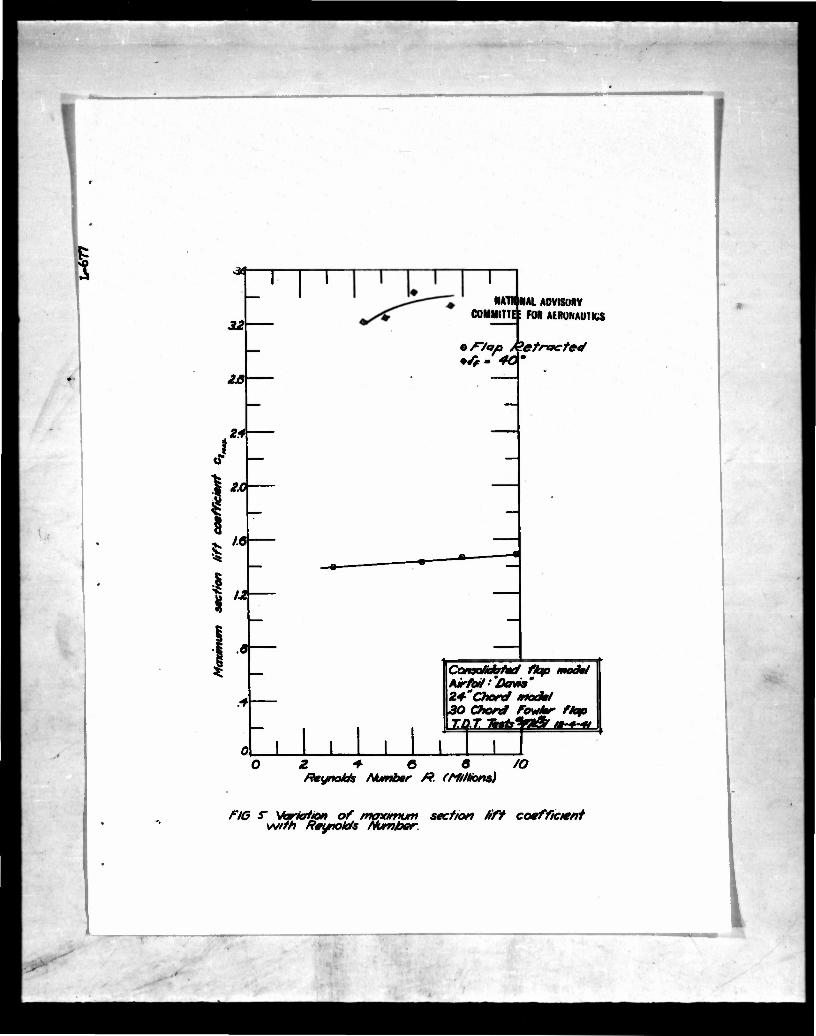
Lift curves for the Davis model plotted against angle of attack are presented in figure I4. for flap deflections of 0C 10*- rr»o 0°, and lj.0°. Soale effect on the maximum lift coefficients for flap deflections of 0° and I(.0° is shown in figure 5. This model gave a maximum life coefficient of about 1.1+ at a Reynolds number of 6,000,000, flap retracted, and about 3>k at the same Reynolds number with the flap deflected I4.O0,
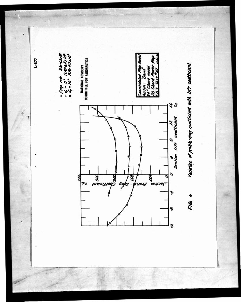
Profile-drag coefficients for the Davis model are plotted against lift coefficient in figure 6 for flap deflections of 0°, 5°, and 10°. This model showed - favorable drag characteristics with flap retracted in the range of lift coefficients useful in cruising and climb. Deflections of the flap to 5° or 10° in the positions determined by the brackets supplied did not Improve the characteristics of the airfoil in this respeot.
!57 •JW"
r -*-
V- C.A.C. Model
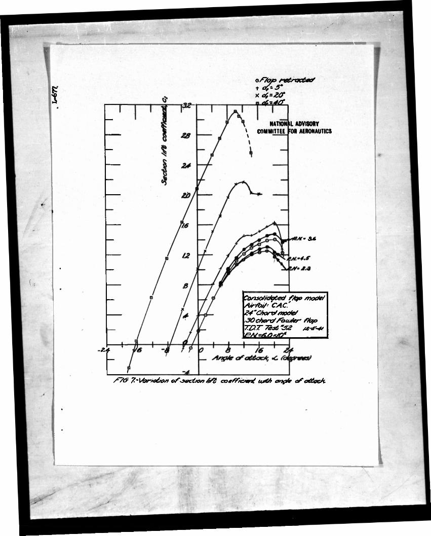
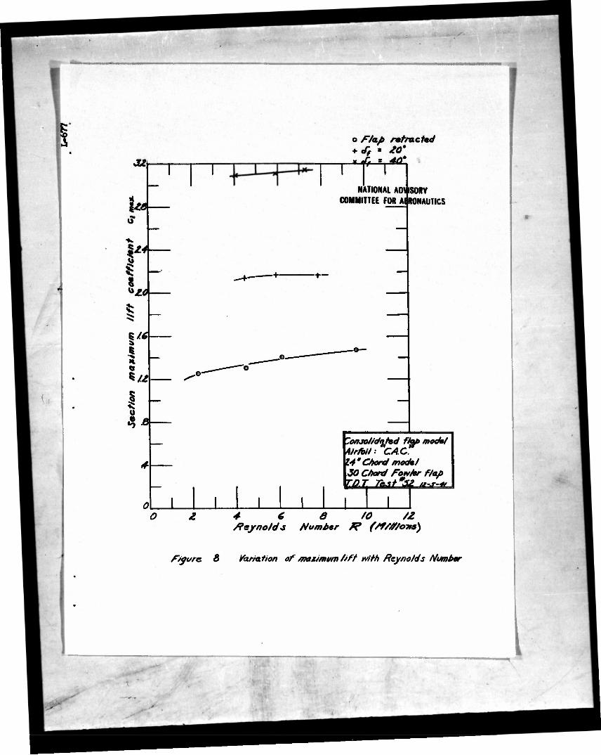
Lift curves for the C.A.C. model plotted against angle of attack are presented In figure 7 for flap deflections of 0°, 5af 20°, and lj.00, Scale effects on the maximum lift coefficients for flap deflections of 0°, 20°, and )+0° are shown In figure 8. This model produced about the same maximum lift coefficients as the Davis model for the flap-neutral condition hut lower values for the flap fully deflected, the maximum lift being about 3.1.
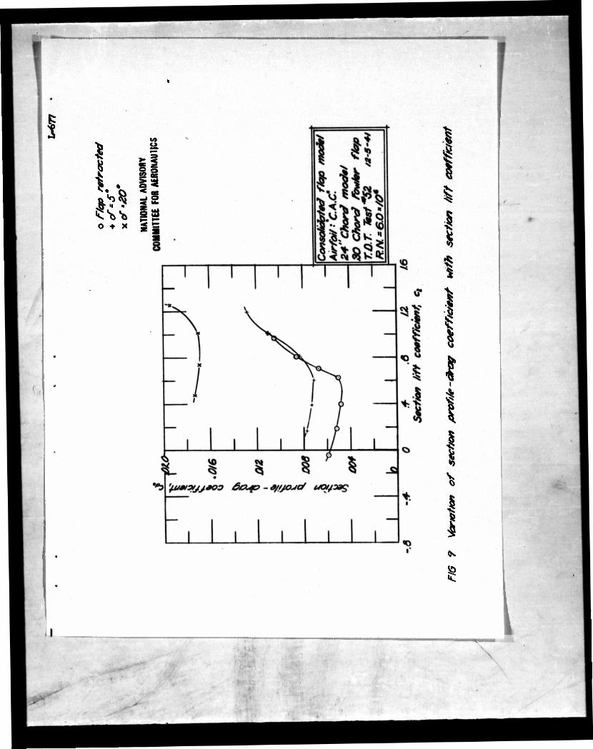
Profile-drag coefficients for the C.A.C. model are plotted against lift coefficients In figure 9 for flap deflections of 0°, 5°; and 20
c. This model was not tested with a flap deflection cf 10° because of the failure of this deflection to show favorable results on the Davis model and because of the increase In drag caused by the 5° deflection. This model gave lower drag coefficients than the Davis model at lift coefficients less than about O.65 but higher drag coefficients at lift coefficients above this value. The minimum drag coefficient was about O.OOI4.8 at a lift coefficient of about O.^.
Low-Drag Model
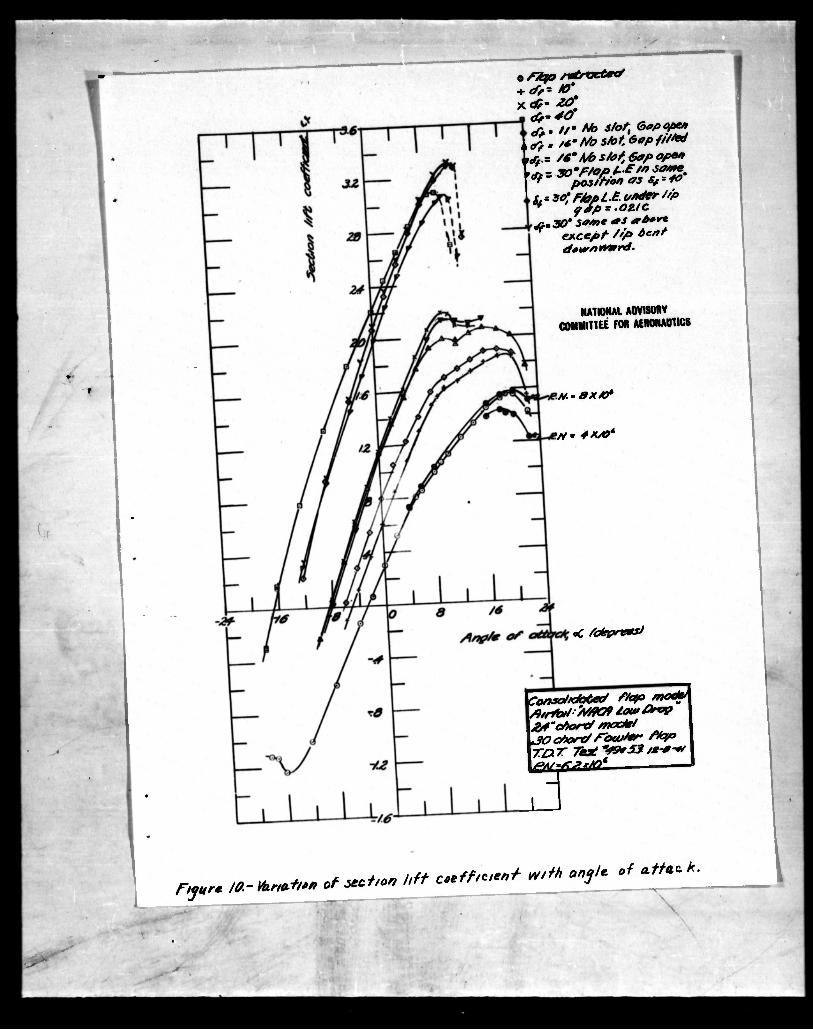
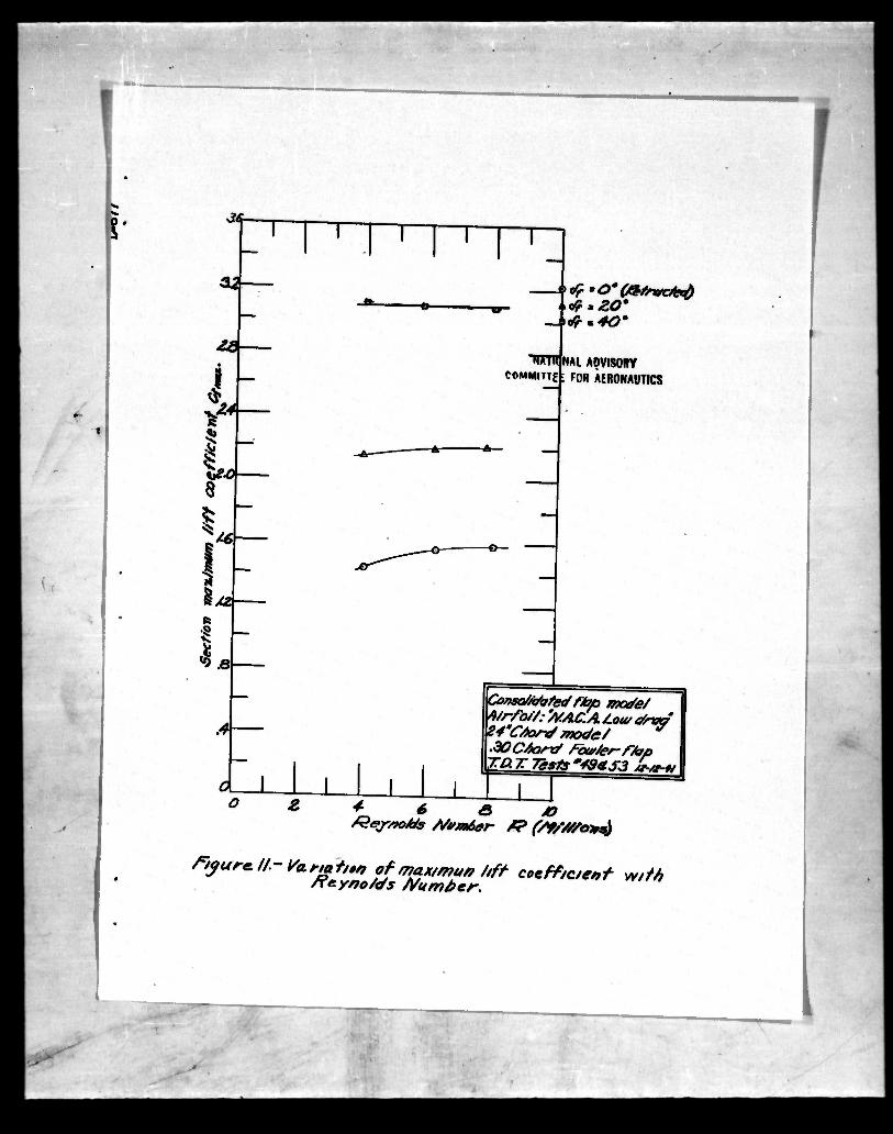
Lift coefficients for the low-drag model plotted against angle of attack are presented in figure 10 for various flap deflections. Scale effects on the maximum lift coefficients are shown in figure 11 for flap deflection* of 0°, 20°, and Jj.0°. The maximum lift coefficient for the model with flap retracted is higher than for either of the other models and about the same (3.1) as for the C.A.C. model with flap deflected 1+0°.
The model was also tested with the flap deflected 30° with the flap leading ed^c in the same position as for the I4.O0 deflection. The maximum lift obtained was about the same as for the i|.0° deflection, being 3.07 against 3.10. The slot shape for either of those condition* did not appear to be very favorable, so the model was tested with the flap deflected 30° but moved back until the flap leading edge was directly under the lip. The gap In this case was 0.021c. The maximum lift obtained In this case was 3.3 (fig. 10). Only half this increase from the previous value can be attributed to increase In ohord of the section. It accordingly appears that the
**$ ••• V. 1
- 5 -
I
I
l
maximum lift of the arrangement might be Improved by cutting back the lip to a position directly above the flap leading edge, If It Is Impractical to extend the flap fully to the existing lip location. Such a condition was not tested because cutting back the lip would spoil the model for pressure-dlstrlbdtlon measurement on any of the existing arrangements.
The metal forming the lip of the model was necessarily relatively thick compared to the lip on the full-scale section. Thia lip had been tapered to a 3harp <JC>,S by removing metal from the lower surface of the lip. the upper surface conforming approximately to the airfoil contour. To Investigate the effect of the iip shape, the lip was bent downwards in a break In such a manner as to duplicate the condition of thinning the lip by removing metal from the top surface of the lip Instead of the lower surface. For this ter.t the flap leading edge was under the lip and the same gap (0.021c) was preserved. The results (fig. 10) showed very little effect.
It is probable that similar flap arrangements on the other models would also Improve the maximum lifts obtained.
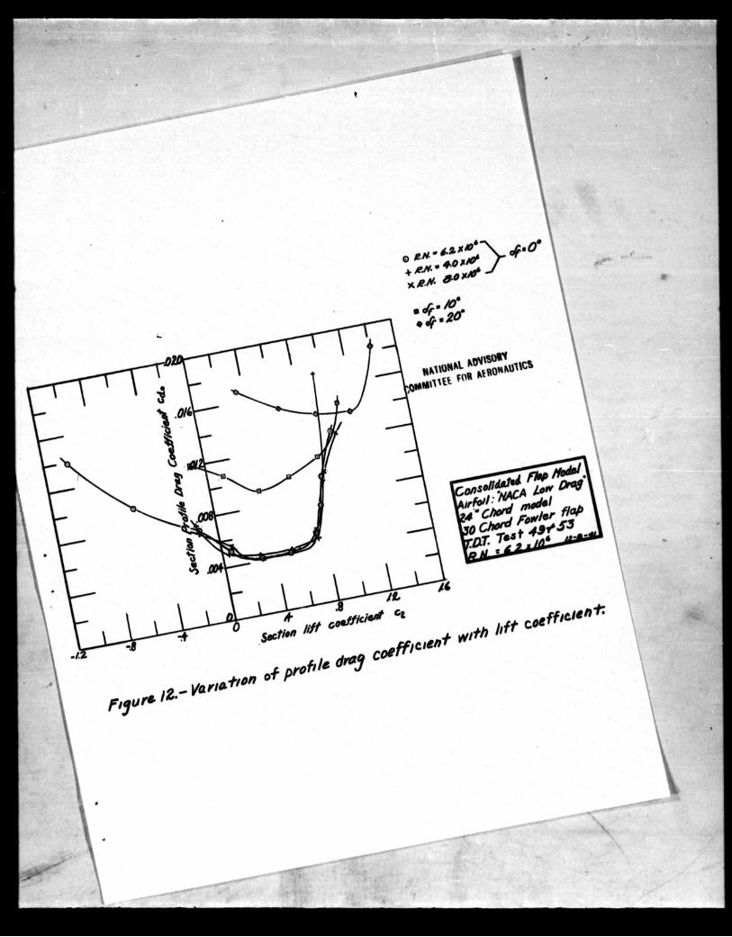
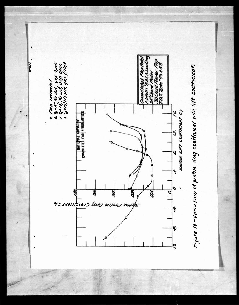
Profile-drag coefficients for the low-drag model are plotted against lift coefficients in figure 12 for flap deflections of 0°, 10°, and 20°. This model gave the lowest drag coefficients of any of the models, flaps retracted, up to a lift coefficient of about 0„7. At higher lift coefficients, without a suitable flap, the drag was less favorable than for the Davis model. Deflection of the flap to the positions determined by the brackets supplied did not extend the low-drag range to higher lift coefficients (fig. 12).
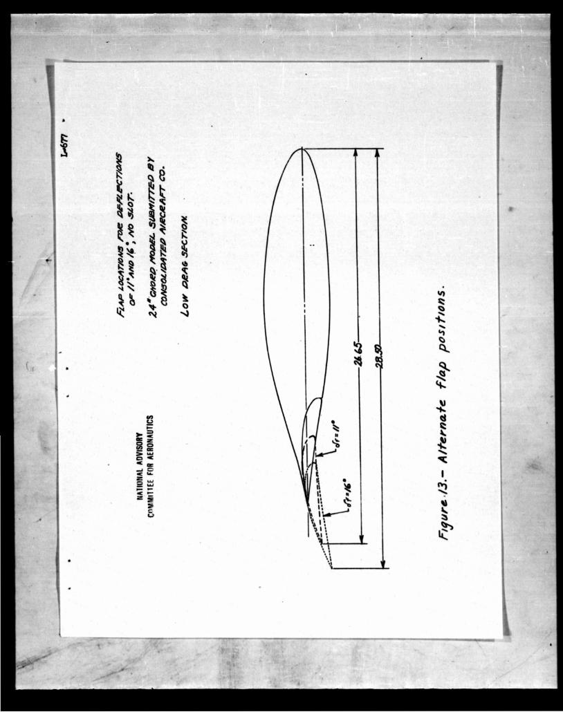
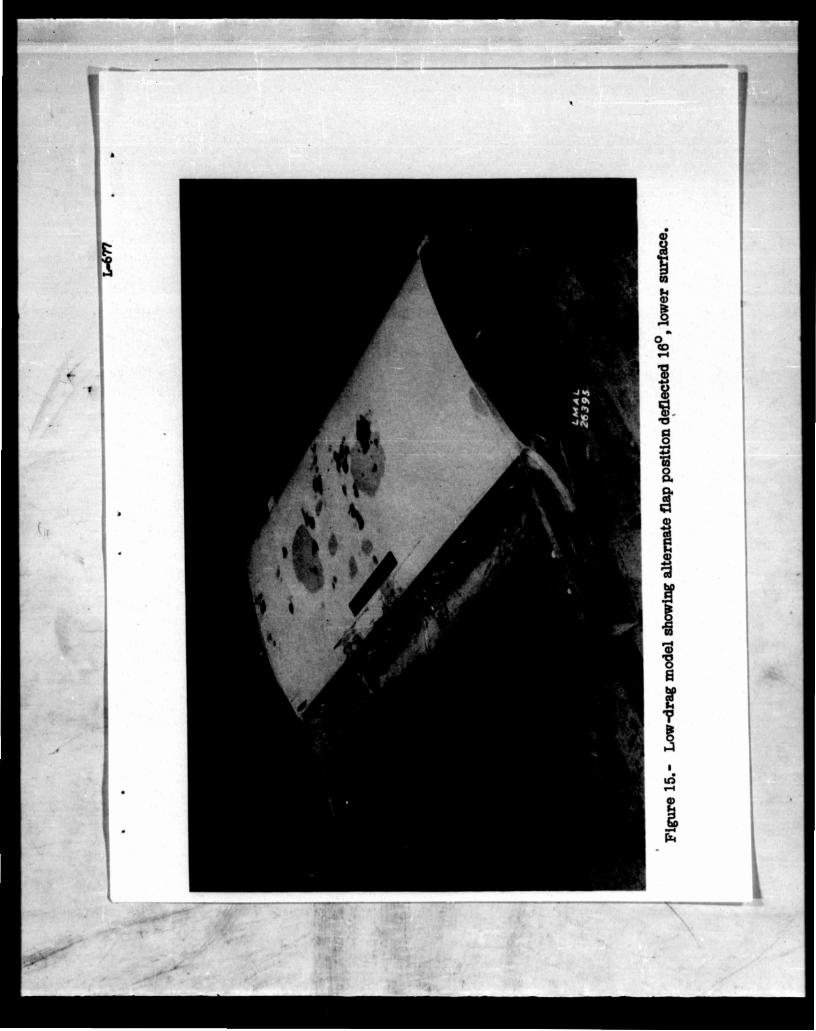
Alternate flap positions were accordingly tested to extend the low-drag range. The new flap positions are shown in figures 13, 1I4., and 15 and involve moving the flap in such a manner as to keep the slot closed. Deflections of 11° and l6° measured from the flap- retracted position were tested and the results shown In figures 10 and 16. The l6° deflection appeared to be the most favorable and allowed low-drag coefficients to be obtained up to a lift coefficient of about 1.2. This position was tested with the gap in the lower surface open (fig. l^) and also with it filled with modeling clay. Filling the gap did not improve the drag. The drag tests with the gap open were made with dams of modeling clay placed in the gap on each side of the measuring position
— 'iMf-
\J'-> IP8- •NS*
..-'••
to prevent deed air from moving elong the gep Into or awey from the measuring position. Nevertheless, the dreg results with the gep open cannot be considered as accurate but probably are indicative of the drags to be expected*
Langley Memorial Aeronautical Laboratory, National Advisory Committee for Aeronautics,
Langley Field, Va.t December 29, l&l* • •;', if
"' • ! •'. 3 :;:
•• (,. •. . • ., ;:' - V W-V'ft'l'
:• if'.'
..ai' s»,
•ffl^'i' "
1^1 • •'
.*(J
•*<*>
©? e*i •»*-» r. :.*\«—*
eij» se"..->! > '".r-ss, ..:;J:. * ': i.V-ft.i "'
'nt -ft*"*:-......- 1 '..:'•., * : ••, . "'."is-! '•">;'•
:i& •o
•i ,. * i ,1*'
,;, *-..?.: '-. •; -i'" "St*o*sw»a •' . - •„•>• -fid 'r^'trf ad1* .vitf •
: v.i. •,, *>.'" '•'•:•• •' "• /•••*'ti-ll
!•;.;• ..',- ' :i- •'' •- *.-J:.': ;;:,r. ' :s " 1-•{,
. >V ' '.- : •'• f,'; ' ": "•'• '. .. - ' *1 . "Jit'i ,:
' ..; '• -. •••.. ••',- •.; ff l- ••:.•* '
•* .. ; i.;. •.>,!?.•> i _•*••••'*M4
" »• .?•..; • ^ .* ; ;••• «; 5 4T
• < .•i*','"' '..' •: '.•'• s ['•£•'•«:•'*•.tjl
•'"' '••:;•••• i*.'~ t*'~: '*»•"' fr*t|t>
; '.,-'• ,i ,>::--. 1 / vr i - ..'U*-f
:. ;• !.'.•.••» ,;.•;.>.- ?.~«i,-i-i
*::•-,..t; . : j.' }(••:. ••,. ; • i -lisv^S-i
":4i,. ,';,!'•-f^'iiV:; i,::i'; •«,'*'.•••!• •-.
:. ?••-!,- , •. ii-t.i ..;.; :-:"*7.y JJ
54 '< i-^.^
•y •if '"•! •:'•••:'.•;"• :>*S-!'•»-*,; iti,*
..*,•*•'.. 4^'*
'.> '
TvT
!»,',
T
I MATIOLAL
•e//'g*/o'
AOVIKMV FOR AERONAUTIC!
/6 24
Const*****/ /Jtyo moo*
E • * VCK*O« or **««*, m *•«%«** a** a^4f -^ril1
Jtf
3.2
2.6
i o
r 1 ^ i-
£ 1.6
I *
1
T MATH NAL ADVISORY
COMMUTE I FOR AtRUNAUTICS
e/7<ao Retracted *rf- 40"
Canaalkhtmd flap mod*/ Airfoil• Vkrwe" 24-''Chord modal 30 Chord fowMr flop TOT Tk&y&f I*-*-*L
I '»•»•
2 + 6 e /o Reynolds Number r?. CM/tlions)
FIG T Variation of maximum section /iff coefficient with Reynolds Number
I
O + X
8
T— I
\ ,
-&+
or/op retrrxeet/
NATIONAL ADVISORY \ COMMITTEE ^OR AERONAUTICS
?.*• At
)Corxso//da£ed Mqp /node/ yUrrt?// CAC.'
<30 Ghana?fbarftr* ribp TGT 7&sA t£? /*•*••«,
*** 7-Var,«6o„ oS^t^^ ***** ^ ^ ^^^
T I
J*
la
VI
5 I **4 4:
|/4 i •
i «3 4
k •»-
T
o /7a^ retracted
NATIONAL COMMITTEE FOR
ADVJISOBY AERONAUTICS
-+—
"onjo//dated f/ae> mode/ ftr/bit: CAC. K4A'C/tord mode/ 30 CAon/ Fo»/er f/afi KQTt Ttottf MatsM I
1 teynoJds A/umber J? f/f/WHm)
1
i N 5e
O + X
I !
i
t i i 8
o fltr/o rrtroctex/ + <ff- *>' xof- ^
d*-40
i <rf . /*• M> s/of. &*p ftt** L& = /*' M> stot, 6op open •A - vo'F/op t-£"> *•» [* posfa* as Sf--fo
S,* ttfllmUt under "p °* 9Jp = .ozic
except //> oe»f
NMIOHAL ADVISORY C0MMI11EE FOR AERONAUTICS
A/.'9XAO*
1
-Mm 4X/0'
mC fofeprensJ
yponsot/chted Map mc \/itf¥t»/: AW09 low £*op
\30 abort/r~otutor ftapo \ra T Teat *49*53 *****
3
—^m- —
or*
I 1 8
5*
S/2 R
<0.8
4
COMMUTE NAl ADVISORY
FOR AERONAUTICS
Consa/Wofed flap i/xx/e/ 4/r/b//: 'MAC. A /Lou/ e/rva 24'CAon/ mode/ .WCfasr/ Fbur/er-ffarp TO. T 7ests "S34S3 it* &•/*-*/
& * 6 <5 JO ^ejr/fokfs A/vm6er t? (St////o»$
ftQure.lt- Variation of max/muff t/f? coefftc/ettf with /fey/iota's A/umber.
I <i)
5
S; «o 1 *•>
45 II ,, II
O < X +
°PO 4U9WJJ903
f
«R
$
C 1
S'5«
(0 w.o
1st; •H *J
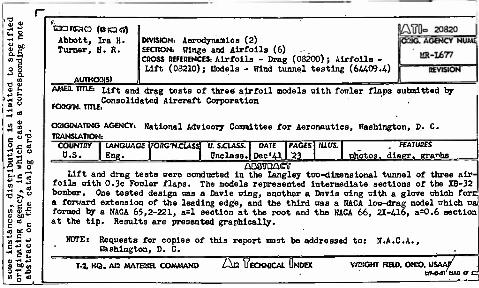
taareaa (otacr) Abbott, Ira H. Turner, H. K.
AUTKOR(S)
DIVISION: Aerodynamics (2) SECTION. Uings and Airfoils (6) CROSS REFERENCES. Airfoils - Drag (08200) ; Airfoils - Lift (08210); Hodels - Bind tunnel testing (6W09.4)
AMEfl. TITLE. Lift and (jrag tasts of three airfoil models nith fouler flaps submitted by Consolidated Aircraft Corporation
FORO-N. TITIE,
OHtGINATING AGENCY. TRANSLATION!
National Advisory Committee for Aeronautics, Washington, D. C.
COUN7BY U.S.
LANGUAGE PORCNCI
Eng. LASS U SJCLASS.
Unclass. DATE PAGES
Dec'q I 23 ILLUS. FEATURES
photos, dlagr. graphs. AB3TOACT
Lift and drag tests uere conducted in the Langley tuo-dimensional tunnel of three air- foils with 0.3c Fouler flaps. The models represented intermediate sections of the XB-32 bomber. One tested design uas a Davis sing, another a Davis oing nith a glove uhich fore a forward extension of the leading edge, and the third nas a HACA lou-drag model uhich ua formed by a NACA 65,2-221, a=l section at the root and the HACA 66, 2X-416, a=0.6 section at the tip. Results are presented graphically.
HDTE: Requests for copies of this report must be addressed to: N.A.C.A., Baahington, D. C.
T-l KQ. AIR MATERIEL COMMAND ZSaUECKNlCAl DNDEX WRIGHT FIELD, OHIO. USAAf W-O-M OAO a:
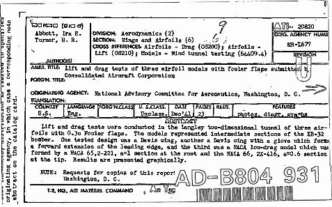
ESDFKIC) (Bia«!) Abbott, Ira H. Turner, H. R.
AUTKQg(S)
f„. DIVISION: Aerodynamics (2) SECTION: Wings and Airfoils (6) . «?•/, CBOSS BEFERENCES: Airfoils - Drag (08200) j Airfoils - Lift (08210); Hodels - Wind tunnel testing (64409 .U)
20820 IG. AGENCY NUMB
MR-L677
REVISION
AMEB. TITLEs Lift and drag tests of three airfoil models with fowler flaps submitt
FOnCN. TITLE:
ORIGINATING AGENCY:
TRANSLATION:
Consolidated Aircraft Corporation
Rational Advisory Committee for Aeronautics, Washington, D.
30. £
" FEATUUfS Photos, diagr. gra"hs
COUNTHY D.S.
LANGUAGE [FOBCNil En&
SXLASS. TJnclass.
DATE Dec'Al
PAGES 23
IlLUS.
ABSTTOACT Lift and drag tests were conducted in the Langley two-dimensional tunnel of three air-
foils oith 0.3c Fowler flaps. The models represented intermediate sections of the XB-32 bomber. One tested design nas a Davis wing, another a Davis wing with a glove which form a forward extension of the leading edge, and the third was a KACA low-drag model which wai formed by a KACA 65,2-221, a=l section at the root and the HACA 66, 2X-416, a=0.6 section at the tip. Results are presented graphically.
NOTE: Requests for copies of this reporl Rashington, D. C.
^a tTss T-i KQ. AK> MATERIEL COMMAND


![TO - apps.dtic.mil · Reproduction Quality Notice This document is part of the Air Technical Index [ATI] collection. The ATI collection is over 50 years old and was imaged from roll](https://static.fdocuments.in/doc/165x107/5c65ade209d3f2826e8cfdfa/to-appsdticmil-reproduction-quality-notice-this-document-is-part-of-the.jpg)

