Representing Three-Dimensional Topography in a DBMS with a ...
14
Representing Three-Dimensional Topography in a DBMS with a Star-Based Data Structure Hugo Ledoux and Martijn Meijers Abstract For storing and modelling three-dimensional topographic objects (e.g. buildings, roads, dykes and the terrain), tetrahedralisations have been proposed as an alternative to boundary representations. While in theory they have several advantages, current implementations are either not space efficient or do not store topological relationships (which makes spatial analysis and updating slow, or require the use of a costly 3D spatial index). We discuss in this paper an alternative data structure for storing tetrahedralisations in a DBMS. It is based on the idea of storing only the vertices and stars of edges; triangles and tetrahedra are represented implicitly. It has been used previously in main memory, but not in a DBMS—we describe how to modify it to obtain an efficient implementation in a DBMS. As we demonstrate with one real-world example, the structure is around 20 % compacter than implemented alternatives, it permits us to store attributes for any primitives, and has the added benefit of being topological. The structure can be easily implemented in most DBMS (we describe our implementation in PostgreSQL) and we present some of the engineering choices we made for the implementation. 1 Introduction Several data models to represent 3D topographic objects (e.g. buildings, roads, the terrain and dikes) and to store them in a database management system (DBMS) have been proposed. Some of them store only the geometry of single objects while H. Ledoux (&) M. Meijers Delft University of Technology, Delft, The Netherlands e-mail: [email protected] M. Meijers e-mail: [email protected] J. Pouliot et al. (eds), Progress and New Trends in 3D Geoinformation Sciences, Lecture Notes in Geoinformation and Cartography, DOI: 10.1007/978-3-642-29793-9_7, Ó Springer-Verlag Berlin Heidelberg 2013 119
Transcript of Representing Three-Dimensional Topography in a DBMS with a ...
Representing Three-DimensionalTopography in a DBMSwith a Star-Based Data Structure
Hugo Ledoux and Martijn Meijers
Abstract For storing and modelling three-dimensional topographic objects (e.g.buildings, roads, dykes and the terrain), tetrahedralisations have been proposed asan alternative to boundary representations. While in theory they have severaladvantages, current implementations are either not space efficient or do not storetopological relationships (which makes spatial analysis and updating slow, orrequire the use of a costly 3D spatial index). We discuss in this paper an alternativedata structure for storing tetrahedralisations in a DBMS. It is based on the idea ofstoring only the vertices and stars of edges; triangles and tetrahedra are representedimplicitly. It has been used previously in main memory, but not in a DBMS—wedescribe how to modify it to obtain an efficient implementation in a DBMS. As wedemonstrate with one real-world example, the structure is around 20 % compacterthan implemented alternatives, it permits us to store attributes for any primitives,and has the added benefit of being topological. The structure can be easilyimplemented in most DBMS (we describe our implementation in PostgreSQL) andwe present some of the engineering choices we made for the implementation.
1 Introduction
Several data models to represent 3D topographic objects (e.g. buildings, roads, theterrain and dikes) and to store them in a database management system (DBMS)have been proposed. Some of them store only the geometry of single objects while
H. Ledoux (&) ! M. MeijersDelft University of Technology, Delft, The Netherlandse-mail: [email protected]
M. Meijerse-mail: [email protected]
J. Pouliot et al. (eds), Progress and New Trends in 3D Geoinformation Sciences,Lecture Notes in Geoinformation and Cartography, DOI: 10.1007/978-3-642-29793-9_7,! Springer-Verlag Berlin Heidelberg 2013
119

others permit us to explicitly store the topological relationships between objects(and also those between the lower-dimensionality primitives of the representationof an object). Geometry models usually store objects with a boundary represen-tation, called b-rep, and one popular data structure used in practice is GML (OGC2007). It can be seen in the overview of Zlatanova et al. (2004) that many topo-logical models are variations of the formal data structure (FDS) (Molenaar 1990;Molenaar 1998), which, unlike its name implies, is a conceptual model—withrules and constraints to preserve the validity—that can be implemented in aDBMS. FDS is a b-rep model in which four primitives are kept (nodes, arc, edgeand face; bodies are implicit), and where the topological relationships betweenthem are stored.
An alternative to b-rep models is to use tetrahedralisations, where 3D objectsare decomposed into tetrahedra and where empty space (e.g. between buildings) isalso decomposed into tetrahedra and integrated in the model.1 Carlson (1987) andPilouk (1996), among others, argue that tetrahedralisations have several advan-tages to represent 3D objects, in the same way that triangulations have advantagesin 2D (Frank and Kuhn 1986). The advantages the most often cited are: storage issimplified as only one convex primitive is needed (Penninga 2005), spatial anal-ysis operations can perform more efficiently (Ledoux and Gold 2008), and theoverall implementation is simpler, thus more robust. However, tetrahedralisationsalso have theoretical drawbacks as Zlatanova et al. (2004) state in their compar-ison of the different topological models: ‘‘An additional disadvantage of TEN is itsmuch larger database size compared with other representations.’’
As Penninga (2008) states, the storage penalty is true only if all the primitivesof the tetrahedra are explicitly represented (nodes, edges and faces, as with theFDS). He proposes a data structure where only vertices and tetrahedra are repre-sented, and the other primitives are extracted on-the-fly. His data structure can beseen as a variation of Simple Features (OGC 2006): vertices are stored in one tableand have an ID, and one tetrahedron is formed by the concatenation of 4 vertex IDsinto one series of bits. He ensures that all tetrahedra are correctly oriented (i.e. theordering of the vertices is the same for all tetrahedra), which speeds up spatialanalysis and the incremental update of a model.
While Penninga (2008)’s data structure is compact—it takes only about 20 %more space than Oracle Spatial’s polyhedra for a few tested real-world datasets—the topological relationships between the tetrahedra are not explicitly stored(neither adjacency between tetrahedra nor incidence from one tetrahedron toprimitives in other tetrahedra). That means that spatial analysis operations willperform slowly on big datasets, and so will incremental updates to a model.Penninga (2008) advocates using an auxiliary spatial index for each tetrahedron,such as an R-tree (Guttman 1984), although that has not been implemented nor
1 Notice that this model is often called ‘‘TEN’’, which stands for either TEtrahedral Network,TEtrahedral irregular Network, TEtrahedronised irregular Network or TEtrahedron Network,depending on the authors. For the purpose of this paper, they are all equivalent and a TEN is atetrahedralisation, as defined in Sect. 2.
120 H. Ledoux and M. Meijers
tested. The main problems with an auxiliary index are: (1) storage space, thebounding box of a tetrahedron (required by the R-tree) has only one point less thanthe tetrahedron itself; (2) a R-tree is a rather complex structure and updatingincrementally a large tree can be slow. Triangulations in 2D often do not index atthe triangle level for the same reasons, see Finnegan and Smith (2010).
We discuss in this paper an alternative data structure for storing tetrahedrali-sations in a DBMS. Instead of storing explicitly tetrahedra, we store only twolower-dimensionality primitives (vertices and edges), and the stars of edges. It hasbeen used previously in 3D in main memory (Blandford et al. 2005), but to ourknowledge no attempts has been made to implement it in a DBMS. We define inSect. 2 the concept of star, which is related to that of a tetrahedralisation. Oneimportant advantage of our star-based structure is that it permits us to avoid the useof an auxiliary 3D spatial index, instead the topological relationships between thetetrahedra are exploited (only a standard B-tree is needed to index the tetrahedra).As explained in Sects. 3 and 4, the structure is very compact (around 20 %compacter than that of Penninga (2008)’s) and can be implemented easily in aDBMS. We have implemented it in PostgreSQL, and tested it with one real-world3D city model. We are currently working on the development of the structure, andin Sect. 5 we discuss some of the engineering choices we made so far, and ourfuture challenges.
2 Constrained Tetrahedralisation and Stars
2.1 Tetrahedralisation
Given a set S of points in 3D space, a tetrahedralisation decomposes the convexhull of S into non-overlapping tetrahedra. It is possible to construct the Delaunaytetrahedralisation (DT) of S, i.e. a tetrahedralisation where every tetrahedron hasan empty circumsphere; the DT has desirable properties that make them popular inseveral domains.
2.2 Constrained Delaunay Tetrahedralisation
If the input set contains also edges and/or surfaces (boundaries that have to berespected in the tetrahedralisation; think of a 3D city model, the walls of thebuildings have to be present in the resulting tetrahedralisation), then the problem ismore complex.
In 2D, a constrained Delaunay triangulation can be used, Fig. 1a shows anexample. However, as Shewchuk (2002) explains, in 3D there are two approaches.The first one is the conforming DT, where additional vertices (known as Steiner
Representing Three-Dimensional Topography in a DBMS 121

vertices) are inserted to ensure that edges/surfaces are recovered (these extravertices do not modify the shape of the surfaces/polyhedra). The main problem fora data structure is that several new vertices can be required (Cohen-Steiner et al.2004), and that would require more space.
The second solution, the one we use in this paper, is the constrained Delaunaytetrahedralisation (CDT) (Si 2008), as Fig. 1b shows. The tetrahedra created arenot fully Delaunay, but this is not a problem and the number of newly insertedvertices is minimised in comparison to the previous two approaches. Anotheradvantage is that robust and efficient implementations of CDTs exist, as they areextensively used in engineering.
2.3 Stars and Links
Let v be a vertex in a d-dimensional triangulation. Referring to Fig. 2, the star of v,denoted star(v), consists of all the simplices that contain v; it forms a star-shapedpolytope. For example, in 2D, all the triangles and edges incident to v form star(v),but notice that the edges and vertices disjoint from v—but still part of the trianglesincident to v—are not contained in star(v). Also, observe that the vertex v itself ispart of star(v), and that a simplex can be part of a star(v), but not some of its facets.
The set of simplices incident to the simplices forming star(v), but ‘left out’ bystar(v), form the link of v, denoted link(v), which is a (d " 1) triangulation. Forexample, if v is a vertex in a tetrahedralisation, then link(v) is a two-dimensionaltriangulation formed by the vertices, edges and triangular faces that are containedby the tetrahedra of star(v), but are disjoint from v.
(a) (b)Fig. 1 a Two-dimensionalpolygons representingbuildings footprints, and theirconstrained Delaunaytriangulation. b Three-dimensional representation ofthe same buildings[polyhedra in this case,obtained by extruding thefootprints in (a)] and theirconstrained Delaunaytetrahedralisation (for clarityonly the tetrahedra inside thepolyhedra are shown here)
122 H. Ledoux and M. Meijers

The closely related concepts of star and link also apply to edges in 3D: in Fig. 3star(ab) is formed by all the incident simplices (6 in this case), and link(ab) is a1-dimensional triangulation (a polyline).
3 A Star-Based Data Structure
To our knowledge, Cline and Renka (1984) are the first to design a data structurewhere stars of vertices are used to represent a triangulation, albeit in 2D. Theirstructure is compact, but does not allow incremental updates (which is arguablyimportant for a GIS data model). Shewchuk (2005) uses a star-based data structureto manipulate 3D triangulations, but his structure is very verbose since the star ofevery vertex is stored as a 2D triangulation, itself stored with stars. Blandford et al.(2005) fix both issues with their structure, which is valid for 2D and 3D trian-gulations. Their representation indeed uses about a factor 3 less memory thantraditional representations in 3D and at the same time can be queried anddynamically modified. To achieve this compression, they designed a pointer-lessstructure where each vertex is assigned a label (an integer) and they compressbased on labels: if possible they store the integers using 4 bits (they use differencesbetween the labels to achieve that) and use different optimisations to keep thememory footprint low.
While it would theoretically be possible to implement the compression in aDBMS, we are interested in their basic idea of using labels for vertices and storethe stars of edges in 3D. In a nutshell, a star-based data structure for a tetrahed-ralisation in a DBMS is as follows. For an edge ab of the tetrahedralisation, westore its link as an ordered list of labels. The orientation is consistent with theright-hand rule: if the thumb points from a to b, the vertices of link(ab) are orderedin the direction of the curled fingers of the right hand. In Fig. 3, link(ab) is theordered list is #c; d; e; f ; g; h; c$; notice that this is a circular list and that the startingvertex could be any vertex. The link list is of variable length: its minimum is 2(one tetrahedron) and its theoretical maximum is the number of vertices in thetetrahedralisation minus 2. A tetrahedron is formed by ab and 2 consecutivevertices in the list; a; b; c; d and a; b; h; c are two examples of tetrahedra implicitly
star ( ) link ( )(a)
star ) link( )(b)
(
Fig. 2 The star and the link of a vertex v in a 2D and b 3D
Representing Three-Dimensional Topography in a DBMS 123

represented in link(ab). Notice that the length of the list gives the number ofincident tetrahedra to ab. Also, lower-dimensionality simplices (triangles andedges) are present in links: for instance, referring to Fig. 3, the triangle abc ispresent in the links of its 3 edges. Since the link is an ordered list, the simplicesimplicitly represented are also ordered.
The key idea behind the structure is that if we represent the link of each edge,then we obtain a data structure where relationships such as incidence and adja-cency between tetrahedra are present. It is the overlap between the (ordered) linksthat permits us to represent explicitly that information. Observe that each tetra-hedron is represented in the link of 6 edges, and that since these are ordered, wecan easily navigate from tetrahedron to tetrahedron. We show in Sect. 4.2 a fewexamples of queries.
3.1 Representative Edges
Storing the link for each edge of a tetrahedralisation yields a powerful andtopological data structure, but also one that is not space efficient. Indeed, if theCDT of a set S of n points contains t tetrahedra, then the number e of edges issignificantly higher: Blandford et al. (2005) estimate it at %7=6&t for a CDT wherethe points are uniformly distributed in space.
To reduce the number of edges whose star is stored, we store only the repre-sentative edges (RE), as Blandford et al. (2005) suggest. If the label given to eachvertex is an integer, a RE is one where its 2 vertex labels are either odd or even. Ifwe randomly label the vertices, that should reduce by a factor of about 2 thenumber of edges to be stored and still permits us to represent at least once eachtriangle and each tetrahedron (which is fundamental to ensure that all topologicalrelationships are present). Indeed, it ensures that each triangle has at least one RE:
a
b
c
h
g
f
e
d
Fig. 3 The link of the edgeab in 3D is formed by thebold dashed polyline(c; d; e; f ; g; h; c)
124 H. Ledoux and M. Meijers
a triangle has either 3 REs (3 odd or 3 even labels) or one RE (1 odd/2 even; 2 odd/1 even).
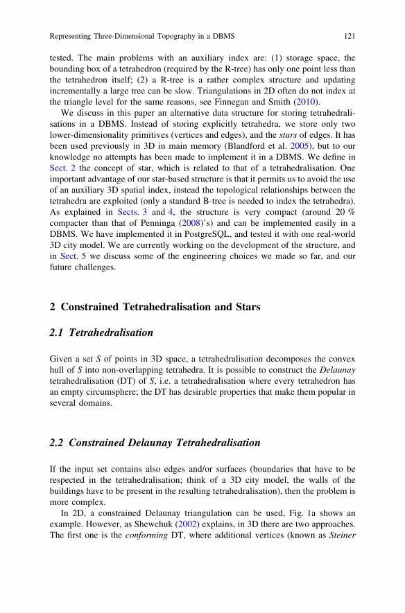
Figure 4 shows the same 6 tetrahedra as Fig. 3 where the REs are highlighted(in bold). It can be seen that out of the 19 edges, 6 are representative, and that eachtriangle contains at least one RE.
3.2 Storage Space
Evaluating the theoretical storage space is difficult since the number of tetrahedrain a CDT depends on the locations of the points and the constraints. However, toobtain an order of magnitude, we can state that we need on average 3 labels pertetrahedron. Indeed, each tetrahedron has 4 triangles, which are shared by 2 tet-rahedra (if we ignore those on the convex hull); thus 2 triangles per tetrahedron.A triangle has 3 labels, but since it appears in 3 stars and that only half of the edgesare represented, we obtain 1 1
2. Thus: 2' 1 12 ( 3 labels per tetrahedron. Our
experiment with a real-world dataset corroborates that, see Sect. 4.3.
3.3 Attributes
Attaching attributes to the tetrahedra is possible, although one must be carefulsince tetrahedra are present in multiple stars. We exploit the fact that each vertexhas a unique label (which can be ordered) and attach the attributes to the star of theREs whose origin is the lowest; in case there are more than one, the one having thelowest destination is chosen. Given a tetrahedron abcd, we can find out in constanttime which RE stores its attributes. The attributes can be stored either in the same
1
2
3
8
7
6
5
4
Fig. 4 A set of 8 verticesyields a tetrahedralisationwith 8 tetrahedra. Out of thetotal 19 edges the 6representative edges (REs)are stored and shown in bold:h1; 3i, h1; 5i, h1; 7i, h2; 4i,h2; 6i, h2; 8i
Representing Three-Dimensional Topography in a DBMS 125

link list (alternating vertex labels with attributes), or in another list (having thesame length as the list of the star).
3.4 Spatial Indexing: The Tetrahedralisation Itself
An advantage of a star-based structure—or of any structure in which adjacency andincidence relationships are stored—is that a spatial index, such as an R-tree(Guttman 1984), is not necessary to access efficiently the tetrahedra. Instead, thetetrahedralisation itself can be used to determine which tetrahedron contains aquery point q: the adjacency relationships between the tetrahedra are used tonavigate in the tetrahedralisation. The latter can be implemented with the walkingalgorithm as described in Mücke et al. (1999). It is a sub-optimal algorithm that isfavoured by practitioners since it does not require an auxiliary data structure andyields fast practical performances (Mücke et al. 1999; Devillers et al. 2002).
The idea is as follows: starting from a given tetrahedron r, we move to one ofthe neighbours of r (we choose one neighbour such that the query point q and rare on each side of the triangular face shared by r and its neighbour) until there isno such neighbour, then the tetrahedron containing q is r. In Fig. 5, only the greytriangles are visited during the walk.
To minimise the number of triangles visited, the starting triangle should beclose to q. Mücke et al. (1999) investigated a ‘bucketing’ approach where a certainnumber of triangles are randomly selected, and each walk starts from the closestone (selected by a simple Euclidean distance test); it is called the jump-and-walkmethod. The result of a query can be either a tetrahedron, or one representativeedge in that tetrahedron. Modifying this algorithm to start from a representativeedge is trivial.
4 Implementation in a DBMS and Experiments
This section describes a prototype implementation of the star-based data structurein a specific, object-relational DBMS (PostgreSQL), but since the data structure isbased solely on lists of labels, implementing it in another DBMS should be
q
starting triangle
Fig. 5 Walking in a 2Dtriangulation, starting from agiven starting triangle to thequery point q. In 3D theprinciple is the same: thewalk is performed fromtetrahedron to tetrahedron
126 H. Ledoux and M. Meijers

straightforward. Several engineering decisions had to be taken when implementingthe structure in PostgreSQL, and we report here on the main ones.
4.1 PostgreSQL Tables
Figure 6 shows that the schema definition of the data structure is straightforward ifthe DBMS supports an array type of variable length: two tables are created, onetable for vertices (points) and one for representative edges. A unique ID isassigned to each vertex and is stored together with the ordinates of each point. Forthe IDs of the points, the type bigint (64-bit integers) is used since 32-bitintegers would limit the size of the datasets that could be stored. We define thecolumn ‘gid’ as a primary key, which creates a binary-tree index on the column(B-tree). This ensures efficient access and enforces uniqueness.
An edge is stored as a reference to its start and end vertices (the primary key ofthe table is composed of the concatenation of both IDs), and its link is stored as anarray of type bigint (which refer to the gid in the vertex table). At a later stagewe will aim at compressing the array stored for the link (by using differences invertex labels), so that less storage space is needed; this then will have a directimpact on how much data needs to be read from disk by the DBMS. Also, to beable to represent triangles and tetrahedra two custom types are defined. Both typesare a sequence of vertex IDs, where triangles are represented by 3 vertex IDs andtetrahedra by 4. Based on these custom types a view can be defined that ‘glues’ thegeometry of the vertices and edges together to triangles and tetrahedra (performedby a DBMS join).
Fig. 6 Schema definition of the star-based data structure in PostgreSQL
Representing Three-Dimensional Topography in a DBMS 127

4.2 Examples of Topological Queries
We describe how a few typical queries could be performed with a star-basedstructure. All the queries refer to the example in Fig. 7, and the resulting tables inPostgreSQL (Table 1). Since triangles and tetrahedra can be present multiple timesin the structure, querying the structure has to be done with care. For example,tetrahedron h5; 7; 1; 2i is present in the edge table in the links of all its represen-tative edges: h1; 5i, h1; 7i and h5; 7i.
Is tetrahedron h5; 7; 1; 2i present? First, one RE has to be found: h1; 5i is one ofthem. Observe that a RE is found in constant time only by finding locally 2 odd oreven IDs in the tetrahedron. Second, the IDs 2 and 7 have to appear consecutivelyin the link of that edge (which is the case, therefore the tetrahedron is present).What tetrahedra are adjacent to h5; 7; 1; 2i? First, find one RE as above (h1; 5i)and find the position of vertices 2 and 7 in the link. The vertices before and afterthe tuple give 2 adjacent tetrahedra: h1; 5; 6; 7i and h1; 5; 2; 4i. Second, findanother RE of h5; 7; 1; 2i and repeat the same operations in its link. Since we knowthat each triangle is represented in at least one RE, this operation will alwaysreturn the 4 tetrahedra.Total number of tetrahedra? Here we apply the same criteria as for storing attri-butes in Sect. 3.3: the lowest concatenation of the IDs is the one representing thetetrahedron. For instance, tetrahedron h1; 3; 4; 2i is conceptually stored in edgeh1; 3i and not h2; 4i. Thus, it suffices to scan the edge table and take a localdecision to extract tetrahedra.
We are currently investigating which custom functions are necessary for modelling3D topographic datasets. Other examples than the ones already mentioned aboveare insertion of a new point or a constraint, point location, attaching attributes to a
12
3
4
5
6
7
8
Fig. 7 Small exampledataset stored in PostgreSQL,see Table 1 for theinformation that is stored
128 H. Ledoux and M. Meijers

specific tetrahedron, etc. These functions will be programmed in PL/pgSQL (theprocedural language that PostgreSQL offers) or C.
4.3 Experiments With Real-World Data
To test the star-based data structure in PostgreSQL, we have made an experimentwith one real-world dataset. It is the 3D city model of our university campusobtained by extrusion; the process used to construct it is described in Ledoux andMeijers (2011). The original dataset covers an area of 2:3 km2 and has 370buildings. We have created the CDT of the model with TetGen2 (Si 2008). Table 2gives the details of the 3D extruded dataset, and the results of the construction ofthe CDT.
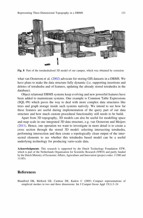
Figure 8 shows a part of the extruded TU Delft campus, once tetrahedralised.As can be seen, each polyhedron is decomposed into a set of tetrahedra. Noticealso that while the tetrahedra representing the ‘air’ are not shown, they are stillstored. In addition, we have constructed six extra planes forming the bounding boxof the dataset and added them to bound the area.
Table 1 Storing thetetrahedra from the exampledataset of Fig. 7. In the linkcolumn, ; means that the linkof the edge does not form acycle, i.e. the edge is on theconvex hull of the dataset
Vertex table
id x y z
1 5.0 2.5 6.02 5.0 11.5 6.03 5.0 6.0 12.04 9.0 6.0 8.05 9.0 6.0 4.06 5.0 6.0 0.07 1.0 6.0 4.08 1.0 6.0 8.0
Edge tableStart End Link[]
2 4 {;, 3, 1, 5}5 7 {6, 1, 2}1 7 {;, 8, 2, 5, 6}1 5 {;, 6, 7, 2, 4}2 6 {;, 5, 7}2 8 {;, 7, 1, 3}1 3 {;, 4, 2, 8}
2 www.tetgen.org
Representing Three-Dimensional Topography in a DBMS 129

The CDT has added around 1,000 vertices to the original model (the Steinerpoints), and the total number of tetrahedra is 47,707, for an input of only 370polyhedra. However, it should be noticed that while the total number of edges inthe CDT is 56,291, less than half of these are REs and thus the edge table in theDBMS is only about 25,000 rows. If the data structure of Penninga (2008) wasused—which is, to the best of our knowledge, the most compact structure forstoring tetrahedralisations in a DBMS—the tetrahedra table would have 47,707rows, and each row would have exactly 4 IDs. The total number of IDs required forthis dataset would thus be 190,828, if we omit the vertex table.
With our structure, the vertex table is exactly the same as Penninga’s. The edgetable has 25,697 rows with 2 IDs (start and end vertices), plus a total of 101,694IDs in all the links (this number was obtained by querying the DBMS; the averagelength of a link is 4.93, the minimum is 3 and the maximum is 28). Thus, the totalis 153,078 IDs, which makes it around 20 % compacter for this real-world dataset.
For populating the DBMS, we have created a program that takes as input theresult of the tetrahedralisation (a list of vertices and tetrahedra) and outputs a list ofREs and their links. Currently, only bulk loading of data is supported in ourprototype.
5 Discussion and Future Work
We have shown that a star-based data structure implemented in a DBMS can beboth compact and topological at the same time, two criteria that are usuallycontradictory. Our structure uses in theory only 3 IDs per tetrahedron, which is animprovement of 33 % over the most compact structure implemented in a DBMS sofar (that of Penninga (2008)). We should add that these results ignore the fact thatwith a non-topological structure an auxiliary spatial index must be used, whichincreases greatly the storage space (3 extra vertices per tetrahedron are needed,plus the size of the tree) and is complex to maintain when objects are deleted. Witha star-based structure, only a standard B-tree is needed, and furthermore less rowsneed to be indexed (in our real-world dataset, we had around twice as manytetrahedra as representative edges). Another strong point of the star-based structureis that it can easily be implemented in any DBMS with two simple tables.
While a star-based structure seems more cumbersome to maintain when thedata are updated, the users need not be aware that this is the structure used. Weplan to add functionalities to the DBMS so that views can be created over theedges and stars so that only features (e.g. buildings) are shown to the user, which is
Table 2 Details concerning the datasets used for the experimentsInput 3D model CDT Star
Vertices Constraints Vertices Edges Triangles Tetrahedra Representative edge5,978 3,982 6,938 56,291 95,420 47,707 25,697
130 H. Ledoux and M. Meijers
what van Oosterom et al. (2002) advocate for storing GIS datasets in a DBMS. Wehave plans to make the data structure fully dynamic (i.e. supporting insertions anddeletes of tetrahedra and of features, updating the already stored tetrahedra in thedatabase).
Object relational DBMS systems keep evolving and new powerful features havebeen added to mainstream systems. One example is Common Table Expressions(SQL-99) which paves the way to deal with more complex data structures liketrees and graph storage inside such systems natively. We intend to see how farthese features are useful during implementation of the query part of our datastructure and how much custom procedural functionality still needs to be build.
Apart from 3D topography, 3D models can also be useful for modelling spaceand map scale in one integrated 3D data structure, e.g. van Oosterom and Meijers(2011). Hence, one operation we want to investigate in more detail is to create across section through the stored 3D model: selecting intersecting tetrahedra,performing intersection and then create a topologically clean output of the inter-sected elements to see whether this tetrahedra based model can be a usefulunderlying technology for producing vario-scale data.
Acknowledgments This research is supported by the Dutch Technology Foundation STW,which is part of the Netherlands Organisation for Scientific Research (NWO) and partly fundedby the Dutch Ministry of Economic Affairs, Agriculture and Innovation (project codes: 11300 and11185).
References
Blandford DK, Blelloch GE, Cardoze DE, Kadow C (2005) Compact representations ofsimplicial meshes in two and three dimensions. Int J Comput Geom Appl 15(1):3–24
Fig. 8 Part of the tetrahedralised 3D model of our campus, which was obtained by extrusion
Representing Three-Dimensional Topography in a DBMS 131

Carlson E (1987) Three-dimensional conceptual modeling of subsurfaces structures. In:Proceedings 8th international symposium on computer-assisted cartography (Auto-Carto 8),Falls Church, VA, pp 336–345.
Cline AK, Renka RJ (1984) A storage-efficient method for construction of a Thiessentriangulation. Rocky Mountain J Math 14:119–139
Cohen-Steiner D, Colin de Verdire E, Yvinec M (2004) Conforming delaunay triangulations in3D. Comput Geom Theor Appl 28:217–233
Devillers O, Pion S, Teillaud M (2002) Walking in a triangulation. Int J Found Comp Sci13(2):181–199
Finnegan DC, Smith M (2010) Managing LiDAR topography using Oracle and open sourcegeospatial software. In: Proceedings GeoWeb 2010, Vancouver, Canada.
Frank A, Kuhn W (1986) Cell graphs: a provable correct method for the storage of geometry. In:Proceedings 2nd international symposium on spatial data handling, Seattle, USA.
Guttman A (1984) R-trees: a dynamic index structure for spatial searching. In: Proceedings 1984ACM SIGMOD international conference on management of data, ACM Press, pp 47–57.
Ledoux H, Gold CM (2008) Modelling three-dimensional geoscientific fields with the Voronoidiagram and its dual. Int J Geograph Inf Sci 22(5):547–574
Ledoux H, Meijers M (2011) Topologically consistent 3D city models obtained by extrusion. Int JGeograph Inf Sci 25(4):557–574
Molenaar M (1990) A formal data structure for three dimensional vector maps. In: Proceedings4th international symposium on spatial data handling, Zurich, Switzerland, pp 830–843.
Molenaar M (1998) An introduction to the theory of spatial object modelling for GIS. Taylor&Francis, London
Mücke EP, Saias I, Zhu B (1999) Fast randomized point location without preprocessing in two-and three-dimensional Delaunay triangulations. Comput Geom Theor Appl 12:63–83
OGC (2006) OpenGIS implementation specification for geographic information-simple featureaccess. Open Geospatial Consortium inc., document 06–103r3.
OGC (2007) Geography markup language (GML) encoding standard. Open GeospatialConsortium inc., document 07–036, version 3.2.1.
Penninga F (2005) 3D topographic data modelling: Why rigidity is preferable to pragmatism. In:Cohn AG, Mark DM (eds) COSIT-Proceedings international conference on spatialinformation theory, Lecture Notes in Computer Science, vol 3693. Springer, pp 409–425.
Penninga F (2008) 3D topography: a simplicial complex-based solution in a spatial DBMS. PhDthesis, Delft University of Technology, Delft, The Netherlands.
Pilouk M (1996) Integrated modelling for 3D GIS. PhD thesis, ITC, The Netherlands.Shewchuk JR (2002) Constrained Delaunay tetrahedralization and provably good boundary
recovery. In: Proceedings 11th international meshing roundtable, Ithaca, New York, pp 193–204.
Shewchuk JR (2005) Star splaying: an algorithm for repairing Delaunay triangulations andconvex hulls. In: Proceedings 21st annual symposium on computational geometry, ACMPress, Pisa, pp 237–246.
Si H (2008) Three dimensional boundary conforming Delaunay mesh generation. PhD thesis,Berlin Institute of Technology, Berlin.
van Oosterom P, Stoter J, Quak W, Zlatanova S (2002) The balance between geometry andtopology. In: Richardson D, van Oosterom P (eds) Advances in Spatial Data Handling-10thInternational Symposium on Spatial Data Handling, Springer, pp 209–224.
van Oosterom P, Meijers M (2011) Towards a true vario-scale structure supporting smooth-zoom.In: Proceedings of 14th ICA/ISPRS workshop on generalisation and multiple representation,Paris, pp 1–19.
Zlatanova S, Abdul Rahman A, Shi W (2004) Topological models and frameworks for 3D spatialobjects. Comp Geosci 30(4):419–428
132 H. Ledoux and M. Meijers