Reported by ACI Committee 374 ACI 374.3R-16Reported by ACI Committee 374 ACI 374.3R-16. First...
5
Guide to Nonlinear Modeling Parameters for Earthquake-Resistant Structures Reported by ACI Committee 374 ACI 374.3R-16
Transcript of Reported by ACI Committee 374 ACI 374.3R-16Reported by ACI Committee 374 ACI 374.3R-16. First...

Guide to Nonlinear Modeling Parameters for Earthquake-Resistant StructuresReported by ACI Committee 374
AC
I 374
.3R
-16

First PrintingSeptember 2016
ISBN: 978-1-945487-19-4
Guide to Nonlinear Modeling Parameters for Earthquake-Resistant Structures
Copyright by the American Concrete Institute, Farmington Hills, MI. All rights reserved. This material may not be reproduced or copied, in whole or part, in any printed, mechanical, electronic, film, or other distribution and storage media, without the written consent of ACI.
The technical committees responsible for ACI committee reports and standards strive to avoid ambiguities, omissions, and errors in these documents. In spite of these efforts, the users of ACI documents occasionally find information or requirements that may be subject to more than one interpretation or may be incomplete or incorrect. Users who have suggestions for the improvement of ACI documents are requested to contact ACI via the errata website at http://concrete.org/Publications/DocumentErrata.aspx. Proper use of this document includes periodically checking for errata for the most up-to-date revisions.
ACI committee documents are intended for the use of individuals who are competent to evaluate the significance and limitations of its content and recommendations and who will accept responsibility for the application of the material it contains. Individuals who use this publication in any way assume all risk and accept total responsibility for the application and use of this information.
All information in this publication is provided “as is” without warranty of any kind, either express or implied, including but not limited to, the implied warranties of merchantability, fitness for a particular purpose or non-infringement.
ACI and its members disclaim liability for damages of any kind, including any special, indirect, incidental, or consequential damages, including without limitation, lost revenues or lost profits, which may result from the use of this publication.
It is the responsibility of the user of this document to establish health and safety practices appropriate to the specific circumstances involved with its use. ACI does not make any representations with regard to health and safety issues and the use of this document. The user must determine the applicability of all regulatory limitations before applying the document and must comply with all applicable laws and regulations, including but not limited to, United States Occupational Safety and Health Administration (OSHA) health and safety standards.
Participation by governmental representatives in the work of the American Concrete Institute and in the development of Institute standards does not constitute governmental endorsement of ACI or the standards that it develops.
Order information: ACI documents are available in print, by download, on CD-ROM, through electronic subscription, or reprint and may be obtained by contacting ACI.
Most ACI standards and committee reports are gathered together in the annually revised ACI Manual of Concrete Practice (MCP).
American Concrete Institute38800 Country Club DriveFarmington Hills, MI 48331Phone: +1.248.848.3700Fax: +1.248.848.3701
www.concrete.org
This guide provides information regarding nonlinear modeling of components in special moment frame and structural wall systems resisting earthquake loads. The reported modeling parameters provide a modeling option for licensed design professionals (LDPs) performing nonlinear analysis for performance-based seismic design of reinforced concrete building structures designed and detailed in accordance with ACI 318.
Keywords: backbone curve; beams; columns; coupling beams; earth-quake-resistant structures; flexure; joints; modeling parameters; nonlinear analysis; performance-based engineering; seismic design; shear; special concrete moment frames; special concrete shear walls; special structural walls.
CONTENTS
CHAPTER 1—INTRODUCTION AND SCOPE, p. 21.1—Introduction, p. 21.2—Scope, p. 2
CHAPTER 2—NOTATION AND DEFINITIONS, p. 32.1—Notation, p. 32.2—Definitions, p. 4
CHAPTER 3—GENERAL, p. 43.1—General, p. 43.2—Backbone curve selection procedure, p. 5
CHAPTER 4—NONLINEAR MODELING PARAMETERS FOR SPECIAL CONCRETE MOMENT FRAMES, p. 5
4.1—Modeling parameters for columns, p. 54.2—Modeling parameters for beams and beam-column
joints (ASCE/SEI 41), p. 5
Jeffrey J. Dragovich, Chair Insung Kim*, Secretary
ACI 374.3R-16
Guide to Nonlinear Modeling Parameters for Earthquake-Resistant Structures
Reported by ACI Committee 374
Mark A. AschheimJohn F. Bonacci
Joseph M. BracciSergio F. BrenaPaul J. BrienenNed M. Cleland
Juan Francisco Correal DazaJoe Ferzli
David C. Fields
Luis E. GarciaGarrett R. Hagen*
Wael Mohammed HassanMary Beth D. Hueste
Luis F. IbarraBrian E. Kehoe
James M. LaFaveAndres Lepage
Adolfo B. Matamoros
Stavroula J. PantazopoulouChris P. PantelidesJose A. Pincheira
Jeffrey RautenbergJose I. Restrepo
Mario E. RodriguezMurat SaatciogluFelipe Saavedra
Guillermo Santana
Mehrdad SasaniShamim A. Sheikh
Myoungsu ShinHitoshi Shiohara
Roberto StarkJohn H. TessemJohn W. Wallace
Tom C. XiaFernando Yanez
*Task group that developed this guide. Alvaro Celestino was also a member of the task group and primary author.
Consulting MembersSergio M. Alcocer Ronald Klemencic Andrew W. Taylor
Special acknowledgements to Laura Basualdo, Anna Birely, Reza Dashtpeyma, Wassim Ghannoum, and Andrew Shuck for their contributions to this guide.
ACI Committee Reports, Guides, and Commentaries are intended for guidance in planning, designing, executing, and inspecting construction. This document is intended for the use of individuals who are competent to evaluate the significance and limitations of its content and recommendations and who will accept responsibility for the application of the material it contains. The American Concrete Institute disclaims any and all responsibility for the stated principles. The Institute shall not be liable for any loss or damage arising therefrom.
Reference to this document shall not be made in contract documents. If items found in this document are desired by the Architect/Engineer to be a part of the contract documents, they shall be restated in mandatory language for incorporation by the Architect/Engineer.
ACI 374.3R-16 was adopted and published September 2016.Copyright © 2016, American Concrete InstituteAll rights reserved including rights of reproduction and use in any form or by
any means, including the making of copies by any photo process, or by electronic or mechanical device, printed, written, or oral, or recording for sound or visual reproduction or for use in any knowledge or retrieval system or device, unless permission in writing is obtained from the copyright proprietors.
1

CHAPTER 5—NONLINEAR MODELING PARAMETERS FOR SPECIAL CONCRETE STRUCTURAL WALLS AND COUPLING BEAMS, p. 7
5.1—Modeling parameters for special structural walls and coupling beams controlled by flexure, p. 7
5.2—Modeling parameters for structural walls and coupling beams controlled by shear, p. 11
CHAPTER 6—SUMMARY AND CONCLUSIONS, p. 12
CHAPTER 7—REFERENCES, p. 12Authored documents, p. 13
CHAPTER 1—INTRODUCTION AND SCOPE
1.1—IntroductionThis guide provides nonlinear modeling parameters that
will assist the licensed design professional (LDP) in the use of performance-based seismic design of new concrete buildings. Performance objectives are assigned for the given structure and compliance with the performance objectives are then evaluated based on the deformation of structural elements rather than evaluated based on strength under prescriptive requirements. Deformations in structural components allow the LDP to understand damage levels related to seismic hazards.
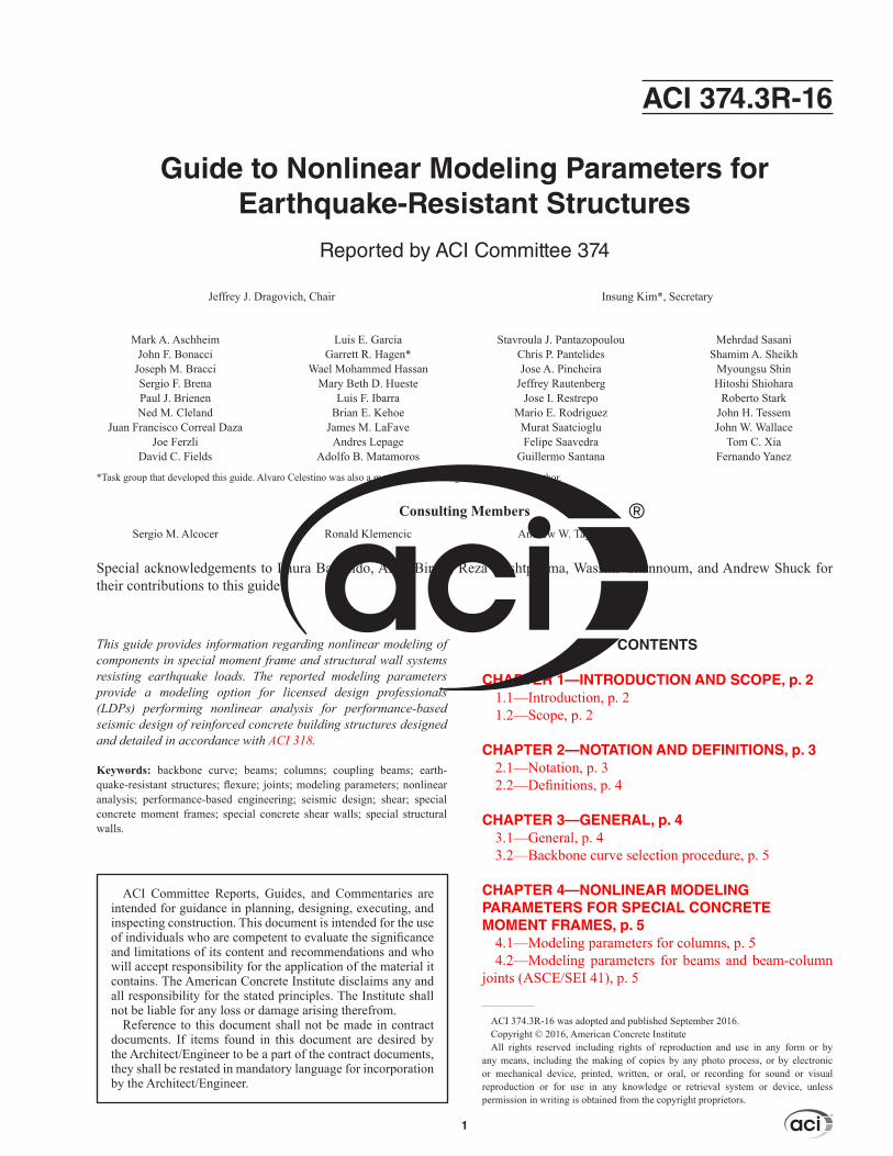
There are currently several documents that provide general analysis procedures for the design of new build-ings using performance-based engineering (ASCE/SEI 7; Structural Engineers Association of Northern California [SEAONC] 2008; Los Angeles Tall Buildings Structural Design Council [LATBSDC] 2014; Pacific Earthquake Engineering Research Center [PEER] [PEER/ATC 2010]). Although these documents provide a means for seismic design indicative of earthquake hazards and acceptance criteria that are similar to ASCE/SEI 41, they do not provide the required information for modeling nonlinear behavior of a structural component based on detailing conditions, such as the development of force-deformation backbone curves shown in Fig. 1.1. This guide provides modeling parameters that can be used to generate the backbone curves of struc-tural members of special moment frame and structural wall systems detailed per Chapter 18 of ACI 318-14.
For example, an engineer modeling the nonlinear defor-mation of a structural wall with specific reinforcement configurations for new design can select from the following three alternatives: 1) develop modeling parameters from existing experimental data; 2) develop and implement a new testing program; or 3) create force-deformation curves using the information in the existing building standard (ASCE/SEI 41) or guideline (ACI 369R) developed for seismic evalu-ation and rehabilitation. The existing experimental data, however, are not always available, and new testing programs may be limited by budget and project schedule. In addition, the modeling parameters in the existing building standard do not always adequately represent the behavior of components designed according to current codes. Furthermore, they may not be directly applied to new design due to incongruences
in parameter definition and requirements across documents. This guide provides a set of nonlinear modeling parameters that can be used without performing one of the three alterna-tives given.
1.2—ScopeThis guide provides information about nonlinear modeling
parameters for:
Fig. 1.1—Generalized force-deformation relations for struc-tural concrete components (ASCE/SEI 41). (Note: a, b, d, e, f, and g are deformations as defined in the reported nonlinear modeling parameter tables.)
American Concrete Institute – Copyrighted © Material – www.concrete.org
2 GUIDE TO NONLINEAR MODELING PARAMETERS FOR EARTHQUAKE-RESISTANT STRUCTURES (ACI 374.3R-16)

(a) Special moment frames extracted from ASCE/SEI 41, for which definitions and requirements are converted to those of the codes for the design of new concrete buildings
(b) Special structural walls and coupling beams extracted from ASCE/SEI 41, for which definitions and requirements are converted to those of the codes for the design of new concrete buildings
(c) Special moment frames and structural walls developed from the latest experimental databases of structural compo-nents compliant with the requirements of Chapter 18 (ACI 318-14) for earthquake-resistant structures.
In regards to (c), the mean and mean minus one standard deviation modeling parameter values are provided for these code-compliant specimen databases in an effort to demon-strate a quantitative representation of data distribution for the LDP. The LDP can select modeling parameters based on ASCE/SEI 41, or the experimental database, depending on project constraints, jurisdiction requirements, or both.
The modeling parameters in this guide are meant to be used for the analytical modeling of structural components in earthquake-resistant systems as described. The guide, however, does not describe global behavior or provide interaction between different systems in the buildings, for example, diaphragms and moment frames.
CHAPTER 2—NOTATION AND DEFINITIONS
2.1—NotationAcv = gross area of concrete section bound by web thick-
ness and length of section in the direction of shear force considered, in.2 (mm2)
Ag = gross area of concrete section, in.2 (mm2)Aj = effective cross-sectional area within a joint in a
plane parallel to plane of beam reinforcement generating shear in the joint, in.2 (mm2) (ACI 318-14 Section 18.8.4.3)
As = area of nonprestressed longitudinal tension rein-forcement, in.2 (mm2)
As′ = area of compression reinforcement, in.2 (mm2)Av = area of shear reinforcement within spacing s, in.2
(mm2)b = width of compression face of member, in. (mm)bw = web width, or diameters of circular section, in. (mm)d = distance from extreme compression fiber to centroid
of longitudinal tension reinforcement, in. (mm)E = effect of horizontal and vertical earthquake-induced
forcesEc = modulus of elasticity of concrete, psi (MPa)Es = modulus of elasticity of reinforcement and struc-
tural steel, psi (MPa)fc′ = specified compressive strength of concrete, psi
(MPa, √fc′ in MPa = 12√fc′ in psi)fy = specified yield strength of reinforcement, psi (MPa)h = height of member along which deformations are
measured, in. (mm)hb = subgrade dimension from absolute base of wall to
grade level, in. (mm)
hc = average height of the beams framing into the joint in the direction of applied shear, in. (mm)
heff = effective shear span of wall, in. (mm)hw = height of entire wall from base to top, or clear
height of wall segment or wall pier, in. (mm)Icr = moment of inertia of cracked section transformed
to concrete, in.4 (mm4)Ig = moment of inertia of gross concrete section about
centroidal axis, neglecting reinforcement, in.4 (mm4)L = length of member along which deformations are
assumed to occur, in. (mm)ℓd = development length in tension of deformed bar,
deformed wire, or plain wire reinforcement, in. (mm)lp = assumed plastic hinge length, minimum of the
following: 0.5lw, the first-story height, and 0.5hw for wall segments, in. (mm)
lw = length of entire wall, or length of wall segment or wall pier considered in direction of shear force, in. (mm)
Mn = nominal flexural strength at section, in.-lb (N-mm)Mpr = probable flexural strength of members, with or
without axial load, determined using the properties of the member at the joint faces assuming a tensile stress in the longitudinal bars of at least 1.25fy and a strength reduction factor ϕ of 1.0, in.-lb (N-mm)
P = design axial force obtained from design load combinations that include overstrength factor or determined from limit-state analysis, lb (N)
Q = generalized force demand in a componentQy = yield strength of a components = center-to-center spacing of transverse reinforce-
ment, in. (mm)V = design shear force obtained from design load
combinations that include overstrength factor or determined from limit-state analysis, lb (N)
Ve = design shear force for load combinations including earthquake effects, lb (N) (refer to ACI 318-14 Sections 18.6.5.1 and 18.7.6.1.1)
Vn = nominal shear strength, lb (N)Vo = shear strength of a column per ASCE/SEI 41 Eq.
(10-3), lb (N)Vp = shear demand on a column at flexural yielding of
plastic hinges per ASCE/SEI 41 Section 10.4.2.2.2, lb (N)
Vsi = nominal shear strength provided by shear reinforce-ment, lb (N)
∆ = generalized deformation, in. (mm)∆y = generalized yield deformation, in. (mm)εy = yield strain of reinforcement, in./in. (mm/mm)θ = generalized deformation, radiansθy = generalized yield deformation, radiansϕ = strength reduction factorϕy = yield curvature at section, 1/in. (1/mm)ρ = ratio of nonprestressed tension reinforcementρ′ = ratio of nonprestressed compression reinforcementρb = ratio of As to bd producing balanced strain conditionρv = ratio of Av to bws
American Concrete Institute – Copyrighted © Material – www.concrete.org
GUIDE TO NONLINEAR MODELING PARAMETERS FOR EARTHQUAKE-RESISTANT STRUCTURES (ACI 374.3R-16) 3