Report type Deliverable D6.1.3 Report name Case … · Sara Tucci-Piergiovanni [email protected]...
45
Grant Agreement 260057 Model-based Analysis & Engineering of Novel Architectures for Dependable Electric Vehicles Report type Deliverable D6.1.3 Report name Case study analysis and safety assessment Dissemination level PU Status Final (third iteration) Version number 3.0 Date of preparation 2013-06-30
Transcript of Report type Deliverable D6.1.3 Report name Case … · Sara Tucci-Piergiovanni [email protected]...

Grant Agreement 260057
Model-based Analysis & Engineering of Novel Architectures for
Dependable Electric Vehicles
Report type Deliverable D6.1.3
Report name Case study analysis and safety assessment
Dissemination level PU
Status Final (third iteration)
Version number 3.0
Date of preparation 2013-06-30

MAENAD D6.1.3 Grant Agreement 260057
The MAENAD Consortium 2 (45)
Authors
Editor E-mail
Stefano Cerchio [email protected]
Authors E-mail
Stefano Cerchio [email protected]
DeJiu Chen [email protected]
Henrik Lönn [email protected]
Renato Librino [email protected]
Carlo LaTorre [email protected]
Sandra Torchiaro [email protected]
Frank Hagl Frank.Hagl@continental-corp
Martin Walker [email protected]
Tahir Naseer Qureshi [email protected]
Sara Tucci-Piergiovanni [email protected]
Fulvio Tagliabò [email protected]
Reviewers E-mail
Henrik Lönn [email protected]
Renato Librino [email protected]
The Consortium
Volvo Technology Corporation (S) Centro Ricerche Fiat (I)
Continental Automotive (D) Delphi/Mecel (S) 4S Group (I)
ArcCore AB (S) MetaCase (Fi) Systemite (SE) CEA LIST (F)
Kungliga Tekniska Högskolan (S) Technische Universität Berlin (D) University of Hull (GB)

MAENAD D6.1.3 Grant Agreement 260057
The MAENAD Consortium 3 (45)
Revision chart and history log
Version Date Reason
0.1 2011-03-08 Document Outline
0.5 2011-05-02 Mid-Term
1.0 2011-08-30 First year Version
2.0 2012-08-31 Intermediate (second iteration)
2.1 2013-06-30 3rd release
2.2 2013-07-10 Merge all contrib. from partners and send for review.
3.0 2013-08 Final version based on review comments from Volvo and 4SG

MAENAD D6.1.3 Grant Agreement 260057
The MAENAD Consortium 4 (45)
List of abbreviations
AADL Architecture and Analysis Design Language
ASIL Automotive Safety Integrity Level
ETA Event Tree Analysis
FEV Fully Electric Vehicle(s)
FMEA Failure Modes and Effects Analysis
FMU Functional Mockup Interface
FTA Fault Tree Analysis
HAZOP Hazard & Operability Analysis
HiP-HOPS Hierarchically-Performed Hazard Origin & Propagation Studies
HRC Heteorogenous Rich Components
MAW MAENAD Analysis Workbench
MMW MAENAD Modelling Workbench
SRA Safety Requirement Allocation
SRD Safety Requirement Derivation
UML Unified Modeling Language
XSLT Extensible Style sheet Language Transformations

MAENAD D6.1.3 Grant Agreement 260057
The MAENAD Consortium 5 (45)
Table of contents
Authors ............................................................................................................................................................... 2
Revision chart and history log ............................................................................................................................ 3
List of abbreviations ............................................................................................................................................ 4
Table of contents ................................................................................................................................................ 5
1 Executive Summary .................................................................................................................................... 6
2 Introduction ................................................................................................................................................. 7
2.1 Purpose and target group ................................................................................................................... 7
2.2 Relation to other project activities....................................................................................................... 7
2.3 Analysis Approach .............................................................................................................................. 7
3 Verification ................................................................................................................................................ 10
3.1 Verification Activities results ............................................................................................................. 10
4 Trials ......................................................................................................................................................... 11
4.1.1 Fault Injection ........................................................................................................................... 13
4.2 Evaluation of ability to support ISO 26262 ....................................................................................... 16
4.2.1 Trial 1:HiP-HOPS Gateway ...................................................................................................... 16
4.3 Evaluation of performance analyses ................................................................................................ 18
4.3.1 Trial 2: Timing Analysis plug-in ................................................................................................. 18
4.3.2 Trial 3: Simulink Gateway ......................................................................................................... 19
4.3.3 Trial 4: MODELISAR FMU import ............................................................................................. 21
4.3.4 Trial 5: Modelica Simulation and EAST-ADL mapping ............................................................. 21
4.3.5 Trial 6: Formal Verification ........................................................................................................ 23
4.4 Evaluation of optimization approaches ............................................................................................. 25
4.4.1 Trial 7: OptiPAL ........................................................................................................................ 25
4.5 Modelling infrastructure .................................................................................................................... 27
4.5.1 Trial 8: Model Exchange ........................................................................................................... 27
4.5.2 Trial 9: AUTOSAR Gateway ..................................................................................................... 28
5 MAW Evaluation ....................................................................................................................................... 30
5.1 Simulink Gateway ............................................................................................................................. 31
5.2 Modelica Exchange .......................................................................................................................... 33
5.3 OptiPAL ............................................................................................................................................ 35
5.4 ASIL allocation with HiP-HOPS ........................................................................................................ 35
5.5 Functional Mock-up Unit Import ........................................................................................................ 36
6 Functional Safety Assessment ................................................................................................................. 42
7 Conclusion ................................................................................................................................................ 44
8 References ............................................................................................................................................... 45
MAENAD D6.1.3 Grant Agreement 260057
The MAENAD Consortium 6 (45)
1 Executive Summary
The goal of the MAENAD project is the development of a methodology and the related tools aimed to an optimal design of electric vehicles, providing support for the management and transfer of information both during the product development lifecycle and during the concept phase to identify optimal architecture based on objective evaluation criteria. MAENAD also includes the development of tools to support the design of embedded systems.
The methodology heavily relies on the paradigm of Model-based design, and is implemented by:
extending the capabilities of the EAST-ADL architecture description language in order to describe and capture the distinctive characteristics of FEV(s);
extending the capabilities of tools that rely on the language, to support the design of automotive embedded systems based on the new engineering scenario and design needs;
developing dedicated tools that, starting from the language, extract the necessary information and provide support for the optimal choice of architectures based on criteria of quality and cost, using the automatic exploration of possible architectural variants.
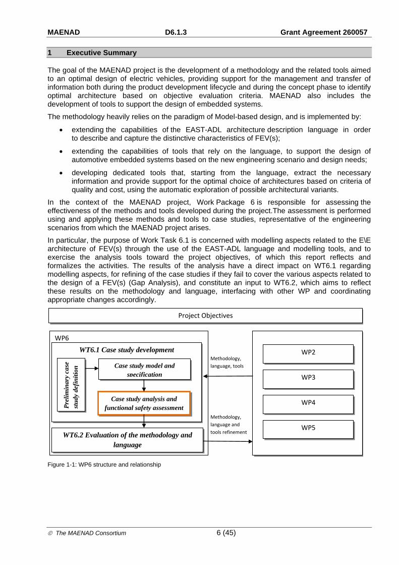
In the context of the MAENAD project, Work Package 6 is responsible for assessing the effectiveness of the methods and tools developed during the project.The assessment is performed using and applying these methods and tools to case studies, representative of the engineering scenarios from which the MAENAD project arises.
In particular, the purpose of Work Task 6.1 is concerned with modelling aspects related to the E\E architecture of FEV(s) through the use of the EAST-ADL language and modelling tools, and to exercise the analysis tools toward the project objectives, of which this report reflects and formalizes the activities. The results of the analysis have a direct impact on WT6.1 regarding modelling aspects, for refining of the case studies if they fail to cover the various aspects related to the design of a FEV(s) (Gap Analysis), and constitute an input to WT6.2, which aims to reflect these results on the methodology and language, interfacing with other WP and coordinating appropriate changes accordingly.
Figure 1-1: WP6 structure and relationship
WP2
WP3
WP4
WP5
WP6
WT6.1 Case study development
Pre
lim
inar
y ca
se
stu
dy d
efin
itio
n Case study model and
specification
Case study analysis and functional safety assessment
WT6.2 Evaluation of the methodology and language
Project Objectives
Methodology,
language and
tools refinement
Methodology,
language, tools
MAENAD D6.1.3 Grant Agreement 260057
The MAENAD Consortium 7 (45)
2 Introduction
2.1 Purpose and target group
The purpose of this deliverable is to:
1. Establish an evaluation framework for the MAENAD project, providing the main trials, steps and analysis approach to be carried out by the partners for measuring the achieved quality of the project outcomes.
2. Summarize the evaluation activities performed by the various working groups performed on the MAENAD Analysis Workbenches and related tools.
3. Report the results of the evaluation activities.
The deliverable is structured as follows:
Trials: describes the evaluation methodology for each tools/plug-in step by step, with the evaluation criteria.
MAENAD Analysis Workbench: report the results of the evaluation activities, the related tools and procedures.
2.2 Relation to other project activities
As evaluation is relevant to almost all of the work packages (WP), and, in addition, requirements gathered for the MAENAD project by WP2 have been committed and established across all the WPs, almost all the MAENAD deliverables have an impact on the evaluation activities.
2.3 Analysis Approach
As previously described, the MAENAD project heavily relies on model-based design and associated techniques to meet the project goals, that is, to provide a comprehensive development framework for the design and development of FEV(s).
The core of the project relies on the enhancement of the EAST-ADL modelling language. The language EAST-ADL is a Domain Specific Language, expressly designed with the focus on the automotive electronic systems. The language offers an effective means to capture and transfer information related to an automotive electronic system across the different layers of the supply chain, as well between application engineers, providing a structured set of viewpoints on the overall architecture and the capability for generating others.
The language itself doesn’t provide capability for simulation and analysis, but provide means to reference models coming from external tools. Furthermore, a set of plugins and tools built on top of the language will be enhanced or developed as extension points to provide support for the analysis of complex systems, or to provide models transformation capability to create a link with external analysis and simulation tools.
The solution of the project for the main goal is focused on different fields of intervention:
Develop capabilities for modelling and analysis support, following ISO 26262, with the main purpose to extend the capability of the EAST-ADL language to support ISO 26262 development process and analysis (FMEA, FTA, risk analysis, ASIL allocation,…).
Develop capabilities for prediction of dependability & performance.
MAENAD D6.1.3 Grant Agreement 260057
The MAENAD Consortium 8 (45)
Develop capabilities for design optimization. This includes the support for the selection of optimal FEV architectures, starting from attributes like performance and cost.
The objectives of WP6 are derived from the main project objectives, and this report will summarize the activities toward their fulfilment:
O4-1: Evaluation of ability to support ISO 26262 and other standards influencing FEV.
O4-2: Evaluation of dependability & performance analyses.
O4-3: Evaluation of optimization approaches.
The fourth objective, “O4-4: Evaluation of suitability of overall methodology for FEV design”, is implicitly satisfied by addressing the above three objectives, and will be a joint work between WT6.1 and WT6.2, in which WT6.1 will exercise MAENAD methods and tools through case studies, collect analysis and experimental results and transfer these results to WT6.2.
The latter WT, starting from those data, will evaluate the fitness of purpose from OEM(s) and stakeholders perspective.
MAENAD can be seen as a project addressing multiple concerns with the goals to provide methods and tools to support development of FEV. A standard "V-cycle" development model can be applied to the project for the delivery of intended outcomes. User requirements are collected by WP2, technical requirements are derived from them and SW development activities and language refinements are performed.
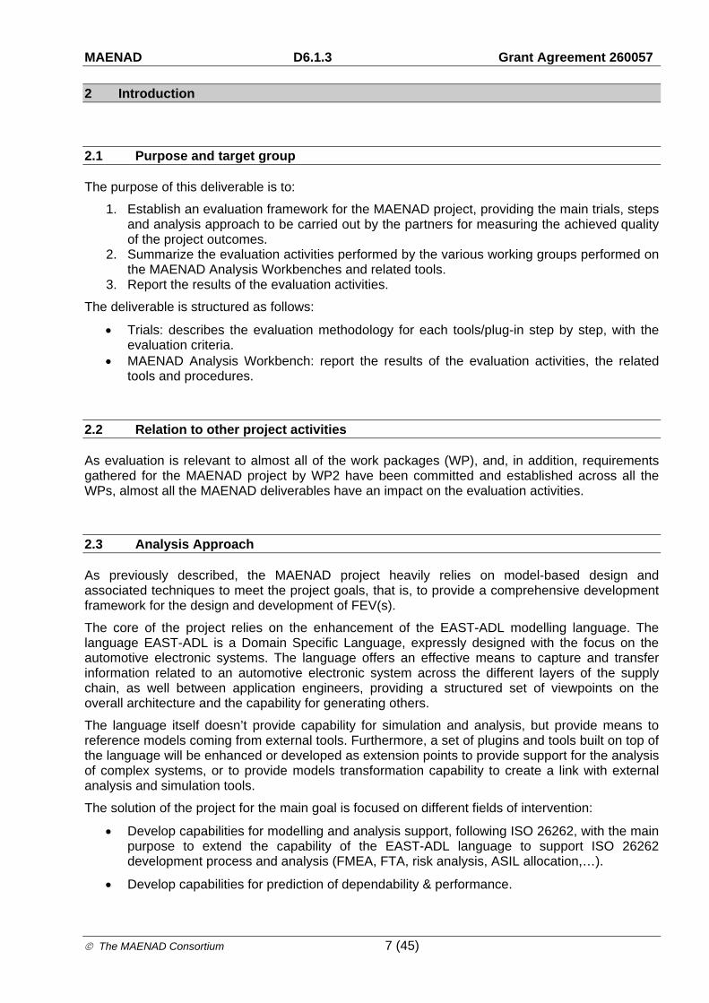
Starting from those concerns and from the project objectives, the analysis of the outputs of the project will follow a verification/validation approach.
Figure 2-1: assessment concept
During the verification phase, it will be evaluated the correct implementation of the technical requirements and specification.
Project MAENAD
Tooling
Needs and Methodology
MAENAD objectives
Modelling, Analysis and Synthesis Concepts
Technical requirements
User needs
User requirements
Automotive System Development Process
Case Study and Assessment
Verification
Verification
Language Definition
Validation
Validation and Verification against user needs and requirements in order to demonstrate the compliance with the user needs, which are directly derived from MAENAD objectives
Verification
Verification of the results against technical requirements, which are the direct input for tool and method realization, in order to demonstrate the correct implementation
Validation

MAENAD D6.1.3 Grant Agreement 260057
The MAENAD Consortium 9 (45)
During the validation phase, it will be evaluated whether the project outputs satisfy the user needs (e.g. the User requirements). This phase will focuses on the investigation of the effectiveness of the developed tools to support the analysis and decision making during the design of a FEV. The work will report the results to WT6.2, as a basis to provide inputs for WP2 “Requirements & Methodology”, WP4 “Language” and WP5 “Tooling”. Part of the activities will be also on the evaluation about the completeness of the analysis that the WP6 will perform on the project outputs. This analysis will serve as a basis for the successive refinements of the use cases inside WP6, in order to guarantees that all the project outcomes will be evaluated.

MAENAD D6.1.3 Grant Agreement 260057
The MAENAD Consortium 10 (45)
3 Verification
During the first part of the project, requirements, needs and use cases have been collected and assigned to work packages. Those requirements cover aspects related to engineering needs and scenario relevant for the design of FEV(s), and include traits derived from an exhaustive analysis on FEV standards and regulations as well as best practices and state of the art methods for the development of complex automotive systems.
The requirements collected will be implemented as new properties and attributes on the modelling elements of the language or as guidelines and modelling patterns using existing constructs, it will also affect the tool support needed for the new engineering challenges.
The verification of the requirements concerning analysis activities consist of a review of the project outputs (language and modelling patterns, tools…) in relation to the requirements collected by WP2. A “coverage criteria” is adopted to assess progress.
The table below show an example of matrix adopted for the analysis
Figure 3-1: Requirements based analysis matrix example.
3.1 Verification Activities results
At present, high-level user requirements have been collected and consolidated by WP2. A second step of analysis and refinement has been performed on the requirements derived from EV standards, resulting in a more concrete and verifiable set of needs that can be more easily reflected on modelling languages, development tools and deployed in the different WPs.
Evolution of the modelling language and analysis tools according to the collected requirements is under way. Verification activities following the above criteria will begin after M12.
Ref. Subject Language/Modelling Req. ref. Analysis Req. ref. Methodology Req. ref. Implem Complet Easy of Demo 1 Demo 2 Demo 3
Insulation ‐ Insulation symbols
‐ Insulation attributes (withstand
f
Insulation analysis
(overall resistance,
)
‐ Deployment of insulation resistance
‐ Addressing insulation monitoring
Heath generation Designing a monitoring system to
prevent dangerous effects to persons,
f fRESS over-current interruption
Modelling of an over‐current
interruption device
RESS short circuit
analysis (current
ff
‐ Designing an overcurrent interruption
device
fConnection of the vehicle to an off-board electric power supply
Designing a means to make impossible
to move the vehicle when connected to
ffIndication of reduced power
Designing a warning to signal to the
driver that the propulsion power is
Driving backwards Designing means to prevent
unintentional switching in reverse
(Parking Designing a warning to indicate
whether propulsion is in the
d bl d hProtection against failures In functional safety development,
include unintended acceleration,
ValidatorValidation criteriaHigh level user requirement
4SG7
4SG8
Medium level user requirement(the text may be more extensive than shown in the box) Tools
EV safety standards/ ISO 6469-1
EV safety standards/ ISO 6469-2

MAENAD D6.1.3 Grant Agreement 260057
The MAENAD Consortium 11 (45)
4 Trials
The purpose of this section is to specify analysis activities to experiment the MAENAD Analysis Workbench, to assess the progress toward the project objectives, with the main focus on the Maenad Analysis Workbench
The analysis is conducted by exercising the tools with three different case studies, representative of FEV(s) subsystems:
Propulsion and power distribution subset with the associated interlock functionality for safety features, and the driving mode selector management
Regenerative braking systems based on an innovative brake by wire distributed architecture.
Driving mode management for electric vehicle, with energy supervision algorithm to support the driver in critical range situation, as well the related HMI to interact with the driver
The picture below provide an overview of a simplified E\E architecture which combine the three subsystems, and that will be used to exercise the MAENAD concepts,

MAENAD D6.1.3 Grant Agreement 260057
The MAENAD Consortium 12 (45)
Each case study will address different aspects of the MAENAD methodology (EV development process, ISO 26262 safety analysis, language capability, modelling aspects, dependability methods, optimization algorithm).
The topics addressed by the individual subsystem are listed in the following table.
Propulsion and power distribution
Range Evaluation
Reg. Braking / EBS
ISO 26262 safety analysis activities x
V&V (Fault injection) x
Language capabilities x x
Timing analysis x x
Dependability & Performances analysis x x
Optimization x
Formal verification x (based on simulation)
x
Table 1 Case studies vs. methodology aspects
See the Table 2 for a relation between the main artefacts of the Analysis Platform and the EV subsystems that are planned to be used to assess the different technologies.
Case Study
Analysis Platform
Propulsion and power distribution
Range Evaluation
Reg. Braking / EBS
AUTOSAR Gateway x (planned)
Timing Analysis x x
Simulink Gateway x
HiP-HOPS Gateway x
Architecture optimization and configuration
x
Plugin for EAST-ADL exchange format EAXML
x x (planned) x
Modelica Exchange x (export)
MODELISAR FMU Import x (export)
Table 2: Case Studies vs. Analysis Platform
Analysis tools have been divided into categories according to the related engineering and technical domain that they address.
The trials specify, for each tool that belongs to the Analysis Platform, the evaluation step and procedure to be carried out to evaluate the technology, and the expected results. This section doesn’t include the results of the evaluation activities; these are presented later in this deliverable.

MAENAD D6.1.3 Grant Agreement 260057
The MAENAD Consortium 13 (45)
It also doesn’t include the evaluation itself, only the methodologies, process, procedures, templates etc.
4.1.1 Fault Injection
Fault injection is a fundamental technique required by ISO26262 to provide evidence that the obtained product complies with the safety requirements. The main goal of this technique is to support the assessment of:
• the correct implementation of functional safety and technical safety requirements during:
• HW/SW integration, system integration and vehicle integration phases, to verify that the integrated elements interact correctly.
• HW development phase.
• SW unit development phase and during SW unit integration on a SW architecture
• the effectiveness of a safety mechanism's diagnostic coverage at the HW/SW development phase and failure coverage at system/vehicle level
One of the main goals of the MAENAD project is to develop capabilities for modelling and analysis support, following ISO 26262. In this context, MAENAD language and related tools could provide support for experimental V&V activities based on fault injection technique with different scope: during the design phase of fault injection experiments, where models of the systems are used to transfer information useful for the design of test experiments according with the methods expressed by the norm, and during the execution of fault injection experiments.
Across the whole WP6 analysis activities, a test bench will be used as a basis to evaluate, to some extent, the correctness of the results of the MAENAD Analysis workbenches and the related fitness of purpose from the user perspective, and to assess the capability of MAENAD to support V&V activities based on fault injection technique.
The test bench, realized with Rapid control prototype technologies, is intended to close the loop between the "design phase" and the "production phase".
The support for the analysis activities falls down in different application fields:
1) Evaluation of the correctness of results of the timing analysis. The effectiveness of the Timing plug-in and the predictability of the Timing analysis engine will be evaluated by comparing the results coming from a virtual analysis and the experimental results of a deployed FEV function on the target HW. Similarly, the same approach will be applied for the evaluation of safety related features that decay in the timing analysis fields, such as the evaluation of the fault detection time interval.
2) Evaluation of the correctness of results of the Dependability plug-in. The correctness of the FMEA & FTA generated automatically by the Dependability plug-in will be assessed through fault injection experiments performed on the deployed functions.
3) Evaluation on the suitability of model “transformation related plug-in” to external simulation engine tools (e.g. Simulink) for V&V activities and model based design of control algorithms. This includes the evaluation of the suitability of the translated Environment model for HIL based testing techniques (simulation of the plant), as well for the development of control algorithm for embedded systems.
4) Evaluation on the suitability of MAENAD modelling language to support design of fault injection experiment and their execution using on a real subsystem.
The test bench is designed to provide support for Fault injection experiment, especially those related to Integration phases (system level and vehicle level) of the safety lifecycle. Focus will be

MAENAD D6.1.3 Grant Agreement 260057
The MAENAD Consortium 14 (45)
on a subsystem of a real vehicle, interaction of this subsystem with the rest of the plant will be emulated through dedicated HIL technologies.
The following picture provide an overview on the physical demonstrator, green boxes highlight the real component of the physical test bench setup. Interaction of the physical components with the emulated subsystem will be done through the communication network.
Figure 4-1:Test bench demonstrator concept and design diagram
ITEM
EVC(simulated)
•HVJB•PRND•Brake pdl
INTERFACES•Motor•Battery•Power Electronics•Accelerator pedal(emulated)
Test Equipment
Environment
(Vehicle,road) HVJB
PRND
FIUEVCRPU
Motor
BatterySys
AccPedal
Environment
(Vehicle,road)
Test Machine control
BrakePedal
PowerElec

MAENAD D6.1.3 Grant Agreement 260057
The MAENAD Consortium 15 (45)
The following picture show the
Brake Accellerator EVC
Stop Start Button
PRND HWJB
Environment simulator & Fault injection
Interconnectivity Box
Figure 4-2: test bench prototype

MAENAD D6.1.3 Grant Agreement 260057
The MAENAD Consortium 16 (45)
4.2 Evaluation of ability to support ISO 26262
This chapter introduces the analysis that will be carried out to evaluate the capabilities of the project outputs to support the ISO 26262 automotive safety standard.
At the present, the EAST-ADL language already includes semantic features to support the development of safety related embedded control systems. The language provides constructs, at different abstraction levels, to capture and transfer information across the supply chain in line with ISO26262. The support from the language covers the concept phase of safety lifecycle, providing semantic for the definition of the Item, traceability of requirements, Hazard identification and risk analysis (definition of hazard, hazardous event, safety goal, ASIL, severity, …) , functional safety concept (safe state, fault tolerant time interval,…) as well during the definition of the technical safety concept.
In addition, the language also provides support for the error modelling, enabling the specification of the behaviour of entities in the presence of errors. Analysis support is provided by external tools.
4.2.1 Trial 1:HiP-HOPS Gateway
Support for safety analysis (FMEA, FTA, ASIL decomposition) is provided externally by the HiP-HOPS analysis tool. The link between the modelling environment and the analysis tool is provided by a dedicated gateway plugin that enables the export of EAST-ADL models (annotated with the necessary error modelling information) to the HiP-HOPS format. This can then be read in by HiP-HOPS to perform the analyses.
The input to the HiP-HOPS plugin is an EAST-ADL error model annotated with HiP-HOPS-compatible failure propagation logic. The error model provides the structural information about the system while the logic provides the information about the failure behaviour of each system entity, which HiP-HOPS uses to model the propagation of failures through the system. The propagation logic (provided in ErrorBehaviours) takes the form of Boolean expressions that relate output FaultFailures of an ErrorModelType (representing e.g. components, functions etc.) to a combination of input FaultFailures and internal failure modes. The model is then transformed by the plugin so that HiP-HOPS can read the information and perform automatic FMEA and FTA.
For ASIL decomposition, the exported error model must also contain relevant ASILs assigned to system-level failures (i.e., those which cause hazards). ASILs are provided in EAST-ADL using SafetyConstraints assigned to the FaultFailures (input/output faults) and optionally InternalFaults (component/function failure modes) of the error model. HiP-HOPS uses its internal model of the system failure propagation to determine which low-level failure modes contribute to which system-level failures (and thus which system-level ASILs) and therefore determines which combinations of ASILs can be assigned to the failure modes and input/output faults of the system.
At present, EAST-ADL and HiP-HOPS provides a good infrastructure for the support of automatic FMEA/FTA analysis. The support for automatic ASIL decomposition is still being developed but prototype support exists; the intention is for the ASIL decomposition capability to become fully integrated, as with FMEA/FTA support. Future enhancements will include the import of the analysis results back into the model and improvements to the exchange of information between the modelling environment and analysis tool, as well as more scalable and effective ASIL decomposition algorithms.
Key points for the analysis
Availability of modelling support for safety oriented analysis in MAENAD Modelling Workbenches (Papyrus, MetaEdit+, and SystemWeaver).

MAENAD D6.1.3 Grant Agreement 260057
The MAENAD Consortium 17 (45)
Effectiveness of translation between EAST-ADL models and HiP-HOPS environment through model transformation (HiP-HOPS gateway).
Effectiveness/correctness of the results of the automated analysis.
Sufficiency of the safety analysis support for meeting the demands of ISO 26262.
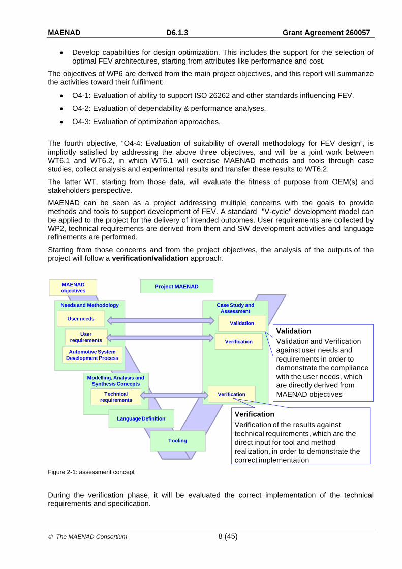
Analysis strategies
ITEM Evaluation Steps
Modelling support for safety oriented analysis in Papyrus environment
1.a Annotation of an Existing Use Case model with the safety related attributes in the different abstraction levels of the language in the Papyrus environment.
Evaluation: Capability of the tools to support the modelling needs and constructs.
Modelling support for safety oriented analysis in MetaEdit+ environment
1.a Annotation of an Existing Use Case model with the safety related attributes in the different abstraction levels of the language in the MetaEdit+ environment.
Evaluation: Capability of the tools to support the modelling needs and constructs.
Modelling support for safety oriented analysis in SystemWeaver environment
1.a Annotation of an Existing Use Case model with the safety related attributes in the different abstraction levels of the language in the SystemWeaver environment.
Evaluation: Capability of the tools to support the modelling needs and constructs.
Automatic translation between EAST-ADL and HiP-HOPS models
1.a Translation of an annotated use case model designed in Papyrus environment to an intermediate format through HiP-HOPS Gateway and import of the file into HiP-HOPS.
1.b Import of the results of the safety analysis back into Papyrus environment.
Evaluation: Level of automation of the gateway. Correctness of the information exchanged between the tools. Review of the correct import of the safety analysis results in the original model.
Effectiveness/correctness of the
Automated FMEA analysis
Analysis will be performed automatically by HiP-HOPS tool.
Evaluation: Review of the results by safety experts through safety reviews. Evaluation metrics will be the correctness of results (FMEA, FTA, ASIL decomposition) and “usability” of the results (ASIL decomposition, for the support to identify a minimal set of optimal solutions among all the possibilities). Validation of the safety goals related to the technical/functional safety requirements implemented through physical fault injection and test bench.
Effectiveness/correctness of the
Automated FTA analysis
Effectiveness/correctness of the
Automated ASIL decomposition

MAENAD D6.1.3 Grant Agreement 260057
The MAENAD Consortium 18 (45)
4.3 Evaluation of performance analyses
This chapter is all about the analysis that will be carried out to evaluate the capabilities of the MAENAD Analysis Workbenches for performance analyses.
Support for performance analysis will be provided through dedicated plug-in for link with Timing analysis engines and state of the art simulation environments.
4.3.1 Trial 2: Timing Analysis plug-in
In the Modeling Analysis Workbench, a dedicated plugin will be provided to perform timing analysis. It will be based on an adaptation of an existing plugin called Qompass, developed by CEA List. This plugin is intended for MARTE models. It takes as input: 1) a description of a software component architecture, each component features operations that can be executed and depending on their allocation to hardware elements require various communication mechanisms to interact with one another – inter-variable communication is assumed when two components are on the same node for instance; 2) software allocation to an hardware architecture (Nodes and buses) whose performance are quantified with some parameters such as processor speed; 3) a list of execution scenarios describing the flow of execution across parts of the software component architecture – each computation or communication steps feature worst-case execution time, each scenario features a timing constraint, typically a deadline for the completion of the flow; 4) a scheduling policy chosen and an allocation of computation and communication steps to tasks on each node – one can use a one-to-one mapping or different schemes, resulting in different loads for each task and hence for each node. The plugin provides an RMA schedulability analysis, which tells whether the list of scenarios as described are schedulable, i.e. deadlines are met or not – a parameter showing how much the system is over- or under-loaded is provided.
To analyse an EAST-ADL model, additional information will then have to be added manually by a user, at least in the first version of the plugin provided, typically the software allocation which is different from the function allocation, the tasks at the level of nodes and the scenarios. In later versions, manual intervention is intended to be reduced as much as possible.
During P2 the plugin has been considerably enhanced by adding:
o An automatic transformation that translates EAST-ADL schedulability relevant information to the MARTE schedulability model
o Enhanced schedulability analysis able to analyse functional allocation without the need of adding implementation -related information
Key points for the analysis
Availability of modelling support for time analysis in MAENAD Modelling Workbenches (Papyrus, MetaEdit+, SystemWeaver)
Effectiveness of automatic transformation
Effectiveness/correctness of the results of the automated analysis.
Suitability for performance analysis in line with ISO26262 (predictability of fault tolerant time interval, fault reaction time, diagnostic test interval)
Analysis strategies
ITEM Evaluation Steps

MAENAD D6.1.3 Grant Agreement 260057
The MAENAD Consortium 19 (45)
Modelling support for timing oriented analysis in Papyrus environment
1.a Annotation of an Existing Use Case model with the timing related attributes in the different abstraction level of the language in the Papyrus environment.
Evaluation: Capability of the tools to support the modelling needs and construct. Formalization of timing requirements and properties in relation to structural model elements
Modelling support for timing oriented analysis in MetaEdit+ environment
1.a Annotation of an Existing Use Case model with the timing related attributes in the different abstraction level of the language in MetaEdit+ environment.
Evaluation: Capability of the tools to support the modelling needs and construct. Formalization of timing requirements and properties in relation to structural model elements
Modelling support for timing oriented analysis in SystemWeaver environment
1.a Annotation of an Existing Use Case model with the timing related attributes in the different abstraction level of the language in SystemWeaver environment.
Evaluation: Capability of the tools to support the modelling needs and construct. Formalization of timing requirements and properties in relation to structural model elements
Effectiveness of automatic generation mechanism for the missing modelling elements
Evaluation: level of automation to complement an initial EAST-AD model so that it is analysable: i.e. generation of a MARTE model based on End-to-end flow descriptions, allocation from function to hardware allocation
Effectiveness/correctness of the results of the automated analysis
Evaluation: comparison of the simulation results with experimental results performed through a physical test bench, fault injection, network time analyses.
4.3.2 Trial 3: Simulink Gateway
The Simulink Gateway is a set of tools\plugins providing a mechanism for bidirectional transformation between EAST-ADL models and Simulink equivalent models. The gateway is intended to provide support for simulation-based analysis to EAST-ADL conformant models, and to enrich to some extent the MAENAD Analysis Workbenches with the features that Matlab/Simulink can provide. The Simulink gateway is composed of a User Interface to the Matlab/Simulink environment that supports the rule-based design of Simulink models conformant to EAST-ADL constraints, and a transformation engine that provides model to model transformation capability between models through intermediate representations.
Key points for the analysis
Effectiveness of modelling support for the Matlab/Simulink – EAST_ADL user interface.
Effectiveness of translation automation from EAST-ADL conformant models to Simulink behavioural models
Effectiveness of translation automation from Simulink behavioural models to EAST-ADL conformant models
Suitability of the Simulink Gateway for Verification and Validation activities
Suitability of the Simulink Gateway for FEV related performances evaluation standards
MAENAD D6.1.3 Grant Agreement 260057
The MAENAD Consortium 20 (45)
Analysis strategies
ITEM Evaluation Steps
Effectiveness of modelling support for the Matlab/Simulink – EAST-ADL user interface
1.a:Development of an EAST-ADL conformant model in Simulink using the related EAST-ADL library blockset and the related plug-in
1.b: Run the Simulink to East-ADL gateway
1.c Import the EAST-ADL equivalent model in MMW editor.
Evaluation: Correctness of the transformation:
data flow,
data types
architecture elements mapping
hierarchical organization of the equivalent model
number and types of supported blockset
Missing elements during the transformation
Support for rule based design (automatic detection of illegal construct, inhibition of Simulink editor functionalities related to illegal construct)
Effectiveness of translation automation from EAST-ADL conformant models to Simulink behavioural models
1.a Export of an existing Use Case model developed with MMW with the Simulink gateway, import the equivalent model in Simulink environment
Evaluation: Correctness of the transformation:
data flow,
data types
architecture elements mapping
hierarchical organization of the equivalent model
missing elements and completeness of transformation
Possibility to execute the equivalent model and effort to make it executable
Number of error/warning raised by the Simulink model checker
Suitability of the Simulink Gateway for Verification and Validation activities
Evaluation:
Possibility to export part of an EAST-ADL model (set up of a test bench, simulation of the environment, plant or non-available elements of an EE architecture)
Suitability of the model to be used in conjunction with Simulink design verifier, steps toward the completion of the model and time saved compared to a design without the export features.
Suitability of the Simulink gateway for FEV related performances evaluation standards
Evaluation: suitability of the exported model for range calculation, number of steps toward the completion of the equivalent model and time saved compared to a design without the export features

MAENAD D6.1.3 Grant Agreement 260057
The MAENAD Consortium 21 (45)
4.3.3 Trial 4: MODELISAR FMU import
The MODELISAR ITEA2 project addressed the design of systems and of embedded software in vehicles. The main output of the project was a specification of an open standardized interface to be used between simulation environments to exchange models and for co-simulation, FMI (www.fmi-standard.org). A Function Mockup Unit (FMU) contains an executable and a Function Mockup Interface (FMI). Tools can use the Function Mockup Interface to properly execute several Function Mockup Units, and thus simulate several components without having access to its internal specification. Providing the capability to exchange EAST-ADL models with the FMI format paves the road for model exchange and simulation of EAST-ADL models.
Key points for the analysis
The FMU import represents model synthesis from external tools, as it makes it possible to reuse the structure defined elsewhere, and to export to external formats. With additional tool support, it would also be possible to synthesize complete FMUs out of an EAST-ADL model. It would mean that components or subsystems of an EAST-ADL model could be simulated based on the MODELISAR concepts. It would require references to executable components from within the EAST-ADL model. At this point, however, the benefit is the consistent definition of component interface between an external component in MODELISAR FMU and its EAST-ADL model.
Analysis strategies
ITEM Evaluation Steps
Evaluation of the capability to import MODELISAR FMI into an EAST-ADL model
Define an MODELISAR Function Mockup Interface specification file for a FMU.
Run MODELISAR FMU import plugin
Assess imported information transformed to EAST-ADL elements
Analysis Results
Modelisar function mockup unit have been imported to EAST-ADL by transforming the definition of a function mockup unit to EAST-ADL EAXML.
4.3.4 Trial 5: Modelica Simulation and EAST-ADL mapping
Modelica is a well-defined simulation language, which includes structural as well as dynamic aspects of a model. A well-defined mapping between Modelica and UML is defined by the OMG. On base of this definition, within the openModelica toolset, a Modelica UML profile for papyrus is defined. The toolset also includes a Modelica code generation, so that UML models can be simulated. For this purpose the Modelica tooling provided by openModelica can be used. On the agenda of the toolset is also the export and import of the FMU exchange format for simulation models. In the ID4EV project Modelica is used for simulation, configuration and testing purposes.
Modelica emphasizes on structured mathematical modelling. Object-orientation is viewed as a structuring concept that is used to handle the complexity of large system descriptions. A Modelica model is primarily a declarative mathematical description, which simplifies further analysis. Dynamic system properties are expressed in a declarative way through equations. The concept of declarative programming is inspired by mathematics where it is common to state or declare what holds, rather than giving a detailed stepwise algorithm on how to achieve the desired goal as is

MAENAD D6.1.3 Grant Agreement 260057
The MAENAD Consortium 22 (45)
required when using procedural languages. This relieves the programmer from the burden of keeping track of such details. Furthermore, the code becomes more concise and easier to change without introducing errors. Thus, the Modelica view of object-orientation, from the point of view of object-oriented mathematical modelling, can be summarized as follows:
1. Object-orientation is primarily used as a structuring concept, emphasizing the declarative structure and reuse of mathematical models.
2. Dynamic model properties are expressed in a declarative way through equations.
3. An object is a collection of instance variables and equations that share a set of stored data.
4. Object-orientation is not viewed as dynamic message passing.
The declarative object-oriented way of describing systems and their behaviour offered by Modelica is at a higher level of abstraction than the usual object-oriented programming since some implementation details can be omitted. This makes Modelica a good candidate for modelling and executing models on analysis level.
On the other hand design aspects can be expressed. Modelica can act as surrogate for an AUTOSAR RTE. Aspects of the RTE as timed execution or event based execution can be expressed in Modelica terms. It is also possible to combine block models (EAST-ADL, AUTOSAR) with Functions (AUTOSAR runnable, C-function). Modes can be defined on block level and control the execution of functions in an AUTOSAR like style. On base of a mode based behaviour, error models can be introduced. Also communication and busses can be simulated using trivial solutions or provided libraries. Timing aspects and TADL constraints can be evaluated on base of Modelica Simulations and constraints (done within ID4EV). Model evaluation is also possible on base of instantiated models, which would allow expressing non-functional properties.
Key points for the analysis
A co-use of ModelicaML and EAST-ADL can easily be done due to the UML profiling mechanisms and the customization towards Papyrus. (see ID4EV demonstrator) Interpretation of EAST-ADL models as ModelicaML models is based on a mapping EAST-ADL <-> ModelicaML (to be developed – structure and dynamic)
Transformation of Modelica ML models into Modelica models
Simulation of Modelica Models on Analysis level
Simulation of Design models by an RTE like execution sematic provided by Modelica
Test and verification of Design Models by using Modelica constraints
Test and Verification of TADL constraints by implementing TADL constraints
Analysis strategies
ITEM Evaluation Steps
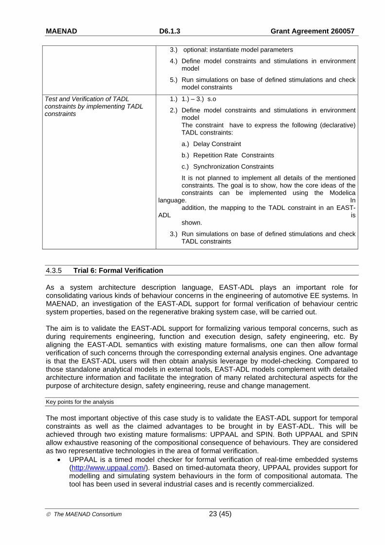
Test and verification of Design Models by using Modelica constraints
1.) Model EAST-ADL model on Analysis and Design level.
2.) Interprete and complete model and as ModelicaML model including model dynamics and modes. (optional define model parameters)
MAENAD D6.1.3 Grant Agreement 260057
The MAENAD Consortium 23 (45)
3.) optional: instantiate model parameters
4.) Define model constraints and stimulations in environment model
5.) Run simulations on base of defined stimulations and check model constraints
Test and Verification of TADL constraints by implementing TADL constraints
1.) 1.) – 3.) s.o
2.) Define model constraints and stimulations in environment model The constraint have to express the following (declarative) TADL constraints:
a.) Delay Constraint
b.) Repetition Rate Constraints
c.) Synchronization Constraints
It is not planned to implement all details of the mentioned constraints. The goal is to show, how the core ideas of the constraints can be implemented using the Modelica language. In addition, the mapping to the TADL constraint in an EAST-ADL is shown.
3.) Run simulations on base of defined stimulations and check TADL constraints
4.3.5 Trial 6: Formal Verification
As a system architecture description language, EAST-ADL plays an important role for consolidating various kinds of behaviour concerns in the engineering of automotive EE systems. In MAENAD, an investigation of the EAST-ADL support for formal verification of behaviour centric system properties, based on the regenerative braking system case, will be carried out. The aim is to validate the EAST-ADL support for formalizing various temporal concerns, such as during requirements engineering, function and execution design, safety engineering, etc. By aligning the EAST-ADL semantics with existing mature formalisms, one can then allow formal verification of such concerns through the corresponding external analysis engines. One advantage is that the EAST-ADL users will then obtain analysis leverage by model-checking. Compared to those standalone analytical models in external tools, EAST-ADL models complement with detailed architecture information and facilitate the integration of many related architectural aspects for the purpose of architecture design, safety engineering, reuse and change management.
Key points for the analysis
The most important objective of this case study is to validate the EAST-ADL support for temporal constraints as well as the claimed advantages to be brought in by EAST-ADL. This will be achieved through two existing mature formalisms: UPPAAL and SPIN. Both UPPAAL and SPIN allow exhaustive reasoning of the compositional consequence of behaviours. They are considered as two representative technologies in the area of formal verification.
UPPAAL is a timed model checker for formal verification of real-time embedded systems (http://www.uppaal.com/). Based on timed-automata theory, UPPAAL provides support for modelling and simulating system behaviours in the form of compositional automata. The tool has been used in several industrial cases and is recently commercialized.
MAENAD D6.1.3 Grant Agreement 260057
The MAENAD Consortium 24 (45)
SPIN is a model checker for formal verification of distributed and concurrent systems (http://spinroot.com). Compared to UPPAAL, the SPIN approach emphasizes the logical aspects of temporal behaviours. It deliberatively avoids the quantitative notion of time, but focuses on the interaction and synchronization of asynchronous processes. This simplification allows SPIN to verify the functional or logical properties of more complex system than timed model checkers usually do.
The intended language validation through UPPAAL and SPIN will be performed in the context of FEV development. By incorporating the analysis engines of UPPAAL and SPIN, the case study will prove and demonstrate the following features of EAST-ADL in regard to behaviour specification and formal verification:
Supporting precise definitions of temporal characteristics for the definition and analysis of safety constraints (required by 4SG#0050, 4SG#0057, 4SG#0058, 4SG#0059)
Supporting assessment of completeness and correctness of the safety requirements (required by 4SG#0048)
Supporting the descriptions of driving profiles (required by CON#2001), physical dynamics (required by CRF#0006b, CRF#0007b), power management procedures (required by CRF#0010b, CRF#0011b, CRF#0013b, CRF#0014b, CRF#0015b), fault tolerance design (required by CRF#0017b, CRF#0018b)
Supporting the generation and precise definition of test cases (4SG#0049a, 4SG#0050)
Supporting the integration with external formalisms (CON#0017, CON#0018, CON#0019)
Analysis strategies
ITEM Evaluation Steps
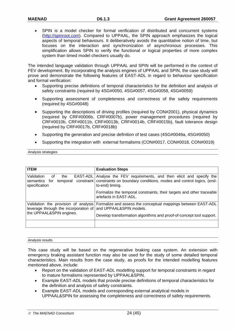
Validation of the EAST-ADL semantics for temporal constraint specification
Analyse the FEV requirements, and then elicit and specify the constraints on boundary conditions, modes and control logics, (end-to-end) timing.
Formalize the temporal constraints, their targets and other traceable artefacts in EAST-ADL.
Validation the provision of analysis leverage through the incorporation of the UPPAAL&SPIN engines.
Formalize and assess the conceptual mappings between EAST-ADL and UPPAAL&SPIN models.
Develop transformation algorithms and proof-of-concept tool support.
Analysis results
This case study will be based on the regenerative braking case system. An extension with emergency braking assistant function may also be used for the study of some detailed temporal characteristics. Main results from the case study, as proofs for the intended modelling features mentioned above, include:
Report on the validation of EAST-ADL modelling support for temporal constraints in regard to mature formalisms represented by UPPAAL&SPIN.
Example EAST-ADL models that provide precise definitions of temporal characteristics for the definition and analysis of safety constraints.
Example EAST-ADL models and corresponding external analytical models in UPPAAL&SPIN for assessing the completeness and correctness of safety requirements.

MAENAD D6.1.3 Grant Agreement 260057
The MAENAD Consortium 25 (45)
Example EAST-ADL models that provide precise descriptions of driving profiles, physical dynamics, power management procedures, fault tolerance design.
Example EAST-ADL models that provide support for the generation and precise definition of test cases.
Proof-of-concept solutions for the mappings and integrations of EAST-ADL with UPPAAL&SPIN.
See Figure 4-3 for an illustration of the intended mapping from EAST-ADL declaration to UPPAAL model for the verification of temporal properties.
UPPAAL Analytical Model EAST-ADL Model
Figure 4-3. EAST-ADL temporal constraint model and its UPPAAL correspondence.
4.4 Evaluation of optimization approaches
The current concept for optimization in EAST-ADL is to develop an optimization architecture built around a central engine based on genetic algorithms that can leverage existing variability constructs in EAST-ADL and previous variability development work as well as linking with the various external analysis tools (for safety, timing, behaviour analysis etc.).
4.4.1 Trial 7: OptiPAL
As planned, the input to the process will be an EAST-ADL model that has been augmented with variability elements to define the potential design space (by establishing possible alternative architectural choices to be experimented with) as well as all data necessary for the analyses/evaluation of each object (e.g. an error model for safety analysis, etc.). An initial function called the Optimization Space Definition Module (OSDM) will take this model and determine the possible design space. The Central Optimization Engine (COE) then uses this as the basis of the optimization process, experimenting with different possibilities. Each design candidate is passed to the Variability Resolution Mechanism (VRM), which generates a new model variant with all optimization variability resolved for that given design candidate. This model variant can then be analysed by the external analysis tools and evaluated on the basis of their results. The COE then tries new possibilities, keeping good candidates and discarding poor candidates, until it is told to stop. It then presents the list of good candidates it has kept so far, which form a Pareto front (a set representing optimal trade-offs between the various multiple optimization objectives - e.g. minimize cost, maximize safety etc.). Each 'optimal' candidate can be generated on demand from the
MAENAD D6.1.3 Grant Agreement 260057
The MAENAD Consortium 26 (45)
original model by the VRM, so the optimization is not creating and storing a huge set of variant models.
Key points for the analysis
Availability of language construct for the definition of cost constraints
Correctness of Cost evaluation
Correctness of Energy consumption evaluation
Correctness of Current Consumption evaluation
Correctness of cable length evaluation
Correctness of power distribution evaluation
Correctness of Safety, Timing analysis etc.
Ensure the generated 'optimal' candidate models are coherent and plausible
Analysis strategies
ITEM Evaluation Steps
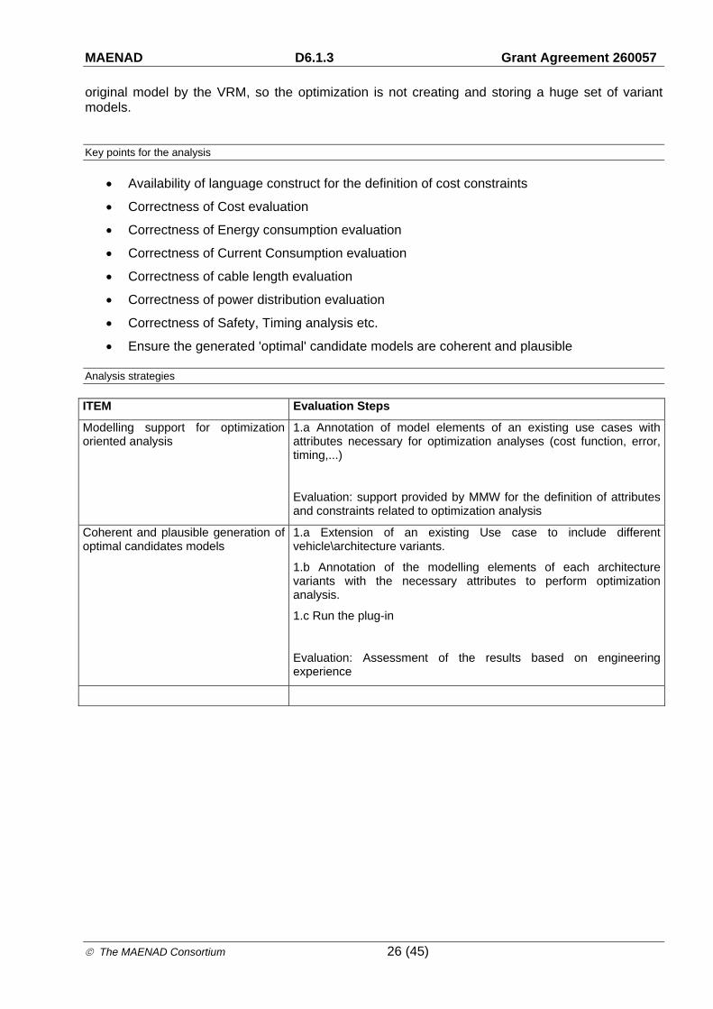
Modelling support for optimization oriented analysis
1.a Annotation of model elements of an existing use cases with attributes necessary for optimization analyses (cost function, error, timing,...)
Evaluation: support provided by MMW for the definition of attributes and constraints related to optimization analysis
Coherent and plausible generation of optimal candidates models
1.a Extension of an existing Use case to include different vehicle\architecture variants.
1.b Annotation of the modelling elements of each architecture variants with the necessary attributes to perform optimization analysis.
1.c Run the plug-in
Evaluation: Assessment of the results based on engineering experience
MAENAD D6.1.3 Grant Agreement 260057
The MAENAD Consortium 27 (45)
4.5 Modelling infrastructure
4.5.1 Trial 8: Model Exchange
The MAENAD Workbench heavily relies on tools and plugin from different tool vendors and institutions. Support for a neutral data exchange format is recommended to grant interoperability between tools and achieve a higher acceptance of the project outputs.
An XML-based exchange format (EAXML), allows tools to exchange EAST-ADL models between UML2 tools and an AUTOSAR-compliant XML format. The schema for the EAXML exchange format is automatically generated from the EAST-ADL meta-model.
At the present, import export support capabilities based on EAXML exchange format has been implemented between MetaEdit+ and SystemWeaver development environment.
Import/export features are currently limited to the Hardware Design Architecture, to investigate the feasibility of the concept.
Key points for the analysis
Export capabilities of models built on “X” development environment to EAXML exchange format.
Import capabilities of models on “X” development environment from EAXML source Bidirectional and consistent exchange of information between tools that belong to different
tools provider.
Analysis strategies
ITEM Evaluation Steps
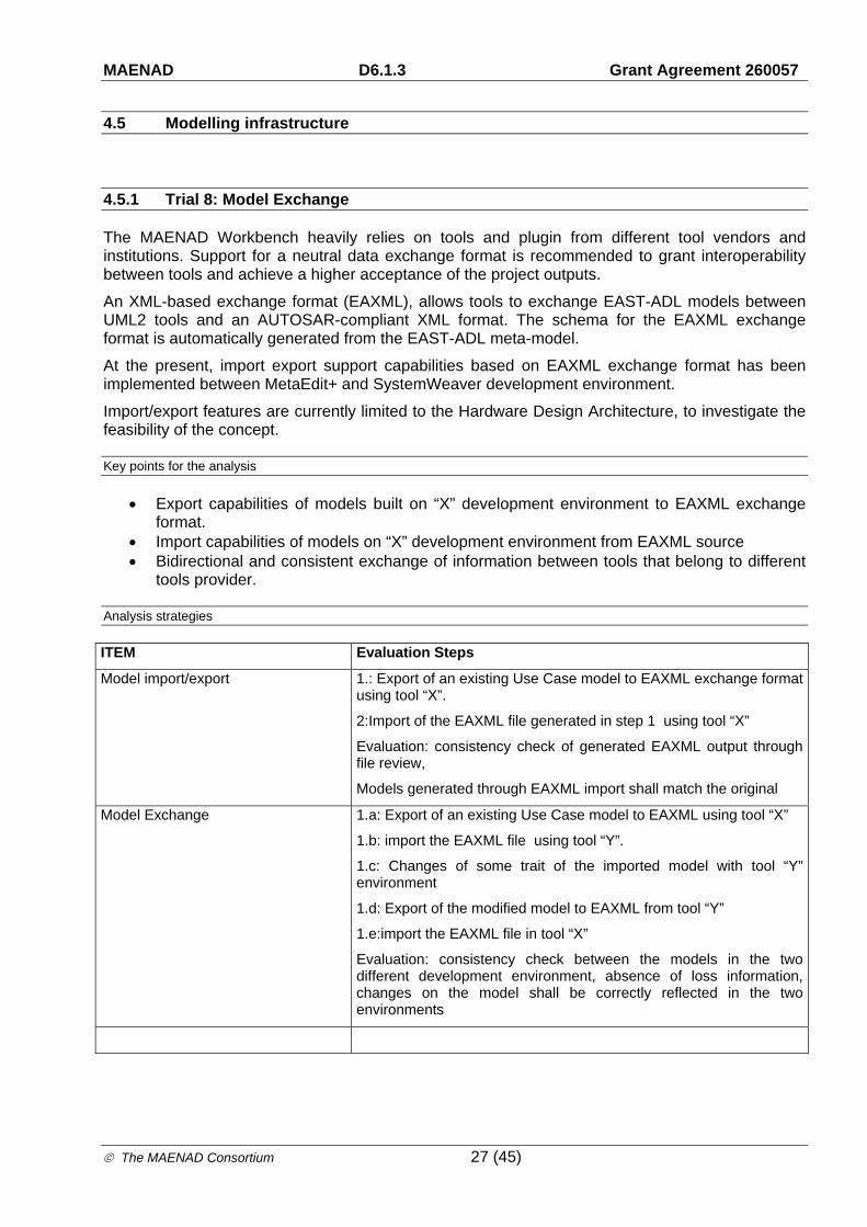
Model import/export 1.: Export of an existing Use Case model to EAXML exchange format using tool “X”.
2:Import of the EAXML file generated in step 1 using tool “X”
Evaluation: consistency check of generated EAXML output through file review,
Models generated through EAXML import shall match the original
Model Exchange 1.a: Export of an existing Use Case model to EAXML using tool “X”
1.b: import the EAXML file using tool “Y”.
1.c: Changes of some trait of the imported model with tool “Y” environment
1.d: Export of the modified model to EAXML from tool “Y”
1.e:import the EAXML file in tool “X”
Evaluation: consistency check between the models in the two different development environment, absence of loss information, changes on the model shall be correctly reflected in the two environments

MAENAD D6.1.3 Grant Agreement 260057
The MAENAD Consortium 28 (45)
4.5.2 Trial 9: AUTOSAR Gateway
AUTOSAR is an open and standardized automotive software architecture, jointly developed by manufacturers, suppliers and tool developers.
EAST-ADL complements AUTOSAR in several ways. The EAST-ADL metamodel is specified according to the same rules of the AUTOSAR metamodel, and AUTOSAR elements can be referenced by EAST-ADL elements. The result is a compositional metamodel where functional architecture aspects and software architecture aspects coexist, and are capable of enriching AUTOSAR with timing constraints, safety constraints and support for safety analysis, support for requirements engineering, variability management.
The goal of the AUTOSAR gateway is to provide an effective means for automatic model transformation from an EAST-ADL design architecture to an AUTOSAR software architecture, supporting the engineers during the design phases.
More precisely, the AUTOSAR gateway takes an EAST-ADL model as an input, i.e. an EAST-ADL design function architecture and hardware description architecture. From this, an AUTOSAR architecture is generated which tries to export as much information as possible. Essentially the core transformation is to map EAST-ADL each elementary function to a runnable entity. Runnables are regrouped into the software components, based on the grouping of elementary functions within non-elementary ones. Also the allocation of elementary functions on the hardware nodes is taken into the account while regrouping runnables into the software components. This prevents regrouping into the same software components those runnable entities that correspond to the elementary functions, mapped to the different nodes. Apart from the software architecture and internal behaviour of each software component, AUTOSAR gateway generates communication, ports, and their interfaces. It also proceeds with the generation of a hardware topology and finally, allocation of software components into the ECUs.
It is significant that now the generation is a twofold process. In the first step, user can generate the AUTOSAR model specified with the created AUTOSAR UML profile. This enables to perform the changes on the generated AUTOSAR architecture within the modelling workbench. The second step of the transformation will take as an input an AUTOSAR model expressed with the AUTOSAR UML profile and will generate the AUTOSAR compliant, XML file – ARXML.
Key points for the analysis
Generation of an AUTOSAR architecture modelled with the AUTOSAR UML profile.
Comparison between an expected and an obtained result of a generation.
Generation of an AUTOSAR xml (ARXML) file from the model stereotyped with the AUTOSAR UML profile.
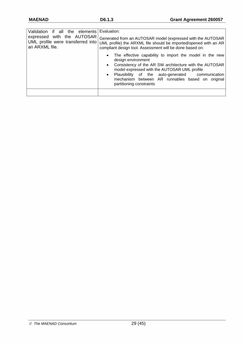
Validation if all the elements expressed with the AUTOSAR UML profile were transferred into an ARXML file.
Correctness of a generated ARXML file in terms of a compatibility with the standard.
Analysis strategies
ITEM Evaluation Steps
Comparison between an expected and an obtained result of a model to model generation (EAST-ADL model to AUTOSAR model)
Evaluation:
Define the expected results of a generation, taking into account implemented strategy for the generation of a software architecture, and compare it with the actual result.
MAENAD D6.1.3 Grant Agreement 260057
The MAENAD Consortium 29 (45)
Validation if all the elements expressed with the AUTOSAR UML profile were transferred into an ARXML file.
Evaluation:
Generated from an AUTOSAR model (expressed with the AUTOSAR UML profile) the ARXML file should be imported/opened with an AR compliant design tool. Assessment will be done based on:
The effective capability to import the model in the new design environment
Consistency of the AR SW architecture with the AUTOSAR model expressed with the AUTOSAR UML profile
Plausibility of the auto-generated communication mechanism between AR runnables based on original partitioning constraints

MAENAD D6.1.3 Grant Agreement 260057
The MAENAD Consortium 30 (45)
5 MAENAD Analysis Workbench Evaluation
The purpose of this section is to describe the analysis activities performed to experiment the MAENAD Analysis Workbench.

MAENAD D6.1.3 Grant Agreement 260057
The MAENAD Consortium 31 (45)
5.1 Simulink Gateway
Two alternative mapping strategies are applied for the mapping from EAST-ADL functional architecture descriptions to Simulink models. The first approach is based on Matlab API, where the Simlink Gateway generates a script file (.m) consisting of Matlab commands for simulink model creation. The second approach is based on Simulink file format, where the Simlink Gateway generates a Simulink file (.mdl) defining the expected model. Both approaches are support by the MetaEdit+ implementation of EAST-ADL by using the through the script language MERL.
Procedures
Experimental model transformation with the regenerative Brake-by-Wire (BBW) system is performed using the MetaEdit+ plugins by KTH and MetaCase. Table 3 provides a snapshot of the Matlab code generated by the Simulink Gateway for the creation of the Simulink model iteratively according to the decomposition hierarchy.
Figure 5-1. The functional architecture description of the regenerative Brake-by-Wire (BBW) system in EAST-ADL and its corresponding Simulink model generated by the Simulink Gateway in ME+.
EAST-ADL Model:
Simulink Model:

MAENAD D6.1.3 Grant Agreement 260057
The MAENAD Consortium 32 (45)
Table 3. A snapshot of the Matlab code generated by the Simulink Gateway in ME+ for the creation of the regenerative Brake-by-Wire (BBW) system in Simulink.
%AdemonstrationoftheexportofEAST‐ADLAnalysisArchitecturemodelinME+toSimulinkmodel
%Author:MechatronicsLab,KTH
%Date:2012‐10‐20
%Specifythenameofthemodeltocreate
fname='FEV_Braking_AL';
%Checkifthefilealreadyexistsanddeleteitifitdoes
ifexist(fname,'file')==4
%Ifitdoesthencheckwhetheritisopen
ifbdIsLoaded(fname)
%Ifitisthencloseit(withoutsaving!)
close_system(fname,0)
end
%deletethefile
delete([fname,'.mdl']);
end
%Createthesystem
new_system(fname);
%Creatingtheblocksandconnectionsrecursively
add_block('built‐in/SubSystem','FEV_Braking_AL/pABS_1','Position',[10122070],'BackgroundColor','yellow');
add_block('built‐in/outport','FEV_Braking_AL/pABS_1/brakeForceDisc_out','BackgroundColor','green');
...
add_block('built‐in/inport','FEV_Braking_AL/pABS_1/wheelSpeed_in','BackgroundColor','green');
add_block('built‐in/SubSystem','FEV_Braking_AL/pABS_2','Position',[10122070],'BackgroundColor','yellow');
....
add_block('built‐in/inport','FEV_Braking_AL/pABS_4/BrakeRef_in','BackgroundColor','green');
add_block('built‐in/inport','FEV_Braking_AL/pABS_4/vehicleSpeedRef_in','BackgroundColor','green');
add_block('built‐in/inport','FEV_Braking_AL/pABS_4/wheelSpeed_in','BackgroundColor','green');
....
add_block('built‐in/SubSystem','FEV_Braking_AL/pBrakeActuator_2','Position',[10122070],'BackgroundColor','yellow');
add_block('built‐in/inport','FEV_Braking_AL/pBrakeActuator_2/brakeForceRequestIn','BackgroundColor','green');
add_block('built‐in/outport','FEV_Braking_AL/pBrakeActuator_2/brakeForceOut','BackgroundColor','red');
....
add_block('built‐in/SubSystem','FEV_Braking_AL/pGlobalBrakeController','Position',[10122070],'BackgroundColor','yellow');
add_block('built‐in/inport','FEV_Braking_AL/pGlobalBrakeController/accRequestedTorque','BackgroundColor','green');
add_block('built‐in/inport','FEV_Braking_AL/pGlobalBrakeController/availableMotorTorque_gbc_in','BackgroundColor','green');
....
add_line('FEV_Braking_AL','pWheelSpeedSensor_4/1','pGlobalBrakeController/4','autorouting','on');
add_line('FEV_Braking_AL','pWheelSpeedSensor_2/1','pVehSpdEst/3','autorouting','on');
add_line('FEV_Braking_AL','wheelSpeed_RL/1','pWheelSpeedSensor_2/1','autorouting','on');
.....
add_line('FEV_Braking_AL','pGlobalBrakeController/1','pABS_4/1','autorouting','on');
add_line('FEV_Braking_AL','pGlobalBrakeController/2','pABS_3/1','autorouting','on');
add_line('FEV_Braking_AL','pGlobalBrakeController/4','pABS_1/1','autorouting','on');
add_line('FEV_Braking_AL','pGlobalBrakeController/3','pABS_2/1','autorouting','on');
%Savethemodel
save_system(fname);

MAENAD D6.1.3 Grant Agreement 260057
The MAENAD Consortium 33 (45)
5.2 Modelica Exchange
Compared with original plans in 4.3.4, the technology of using ModelicaML and EAST-ADL with double stereotypes in Papyrus was not chosen. By building a translator, a more fine-grained mapping could be provided. The MERL language of MetaEdit+ has been used as model-to-text transformation language, to generate native Modelica models, which could be opened in any Modelica-compatible tool.
Procedures
The files for conversion to Modelica are added to a graph in MetaEdit+ using copy/paste, and based on the components in that graph, a Modelica file will be generated, which could be copy/pasted into a Modelica tool, such as OpenModelica.
Evaluation Results
Figure 5-2: A graph of an EAST-ADL model on the left-hand side, and a Modelica model on the right-hand, generated by the Modelica exchange generator.
From the VehiclePlantGraph of the regenerative braking case-study a Modelica skeleton could be generated. This could be populated with Modelica components to provide simulation capabilities. In Figure 5-3, components from the Modelica Standard Library has been used to model a simple vehicle plant.

MAENAD D6.1.3 Grant Agreement 260057
The MAENAD Consortium 34 (45)
Figure 5-3: The Modelica model in Figure 5-2, filled with Model components to model a Vehicle plant
The Modelica exchange is still on a proof-of-concept state. The conclusion from the study is that it is easy to generate Modelica models, which could be executed to provide information on analysis concepts, such as timing, behaviour, etc. There are many possible applications of such an exchange mechanism.

MAENAD D6.1.3 Grant Agreement 260057
The MAENAD Consortium 35 (45)
5.3 OptiPAL
This section describes experimentation with the MAENAD optimization prototype, called OptiPAL.
Procedures
Based on example modelling, the optimisation architecture was defined and refined as explained in D5.2.1.
OptiPal relies on a model being defined in the EPM tool, including the annotations of error propagations and performance.
Evaluation Results
The evaluation o OptiPal has provided insights in several areas:
overall usability and stability of OptiPAL linking external analysis tools to OptiPAL via the generic interface of Analysis Wrappers feasibility of EAST-ADL’s variability modelling concepts for specifying design space
variability feasibility of EAST-ADL’s variability modelling concepts for specifying product line variability relation of design space and product line variability within a single EAST-ADL system
model possible problems with overlaps between design space and product line variability reconcilability of product line variability with multi-objective optimization feasibility of various strategies for representative selection (cf. D5.2.1) feasibility of various strategies for fitness combination, i.e. combining m individual fitness
values of m representatives into a single overall fitness value of the candidate (per objective)
5.4 ASIL allocation with HiP-HOPS
Automatic ASIL allocation and decomposition allows for the efficient allocation of ASILs across a system without violating the safety requirements. It is made possible via an extension to HiP-HOPS and requires very little additional information from an EAST-ADL model other than a normal error model and the definition of hazards (together with their associated ASILs). The approach uses the existing fault propagation information to determine which system elements contribute to which hazards. If there is redundancy between system elements leading to the same hazard, then the ASIL associated with that hazard's safety goal may be decomposed across them; otherwise, each element must be allocated a sufficient ASIL to meet the safety goal for that hazard.
The current implementation of the algorithm is relatively primitive and suffers from scalability problems, and therefore additional longer term work is being undertaken by UOH to find more efficient approaches for ASIL allocation using heuristic approaches, e.g. optimisation. Further information on the current algorithm can be found in D3.2.1.
Procedures
Experimentation with the ASIL allocation process using EAST-ADL models is performed using the EPM HiP-HOPS plugin developed by TUB, enabling analysis of models created in EPM via HiP-HOPS. Initial experiments have already been conducted by UOH on small-scale example models, which have formed the basis for published results. The main example model being used as the main case study is a development of the Brake-by-Wire (BBW) system, initially provided by Volvo. This model is currently being extended by UOH (with assistance from VTEC) with experimental

MAENAD D6.1.3 Grant Agreement 260057
The MAENAD Consortium 36 (45)
ASIL allocation and hazard information for the purposes of the evaluation of the decomposition technique.
It is hoped that the current implementation will be capable of performing a decomposition on the BBW model, but either way it will serve as a useful benchmark for the evaluation of the improved optimisation-based techniques currently under development.
Results from this experimentation work are expected end of July 2013, but subsequent experimentations with improved algorithms will contribute to the ongoing development of the technique throughout the rest of the project.
Evaluation Results
The currently implemented algorithm in HiP-HOPS has already been refined on the basis of smaller experimental results, which show that the technique has a lot of potential but struggles to scale to larger systems. For even small systems with only a handful of elements and a small number of faults, there can still be hundreds or even thousands of possible allocations, and for more realistic systems (e.g. with >50 faults), the algorithm fails to complete on standard computing hardware. Analysis of the BBW model will help to further establish where the precise limits of the current approach are. However, improved algorithms are still in development and may yield a more successful implementation by the end of the project.
5.5 Functional Mock-up Unit Import
The Functional Mock-up Interface (FMI) [6] is a standard that many simulation tools use for interchange of models, and co-simulation. The Functional Mock-up Interface defines the input and output variables of each unit and also the data types of these variables. This is similar to EAST-ADL AnalysisFunctionTypes, so a transformation is possible, simplifying creation of architectural models from simulation models.
Procedures
An input file representing a fictitious environment model was defined in Modelica and exported to an FMU including an FMI file see Figure 5-4.
<?xml version="1.0" encoding="UTF-8"?> <fmiModelDescription fmiVersion="1.0" modelName="EnvironmentModelica" modelIdentifier="EnvironmentModelica" guid="{9db12878-b7ee-450c-9efa-7eb345bb0a9b}" generationTool="OpenModelica Compiler 1.9.0 beta4 (r15030)" generationDateAndTime="2013-08-15T07:23:49Z" variableNamingConvention="structured" numberOfContinuousStates="0" numberOfEventIndicators="0"> <ModelVariables> <ScalarVariable name="WheelSpeed_RR" valueReference="0" variability="continuous" causality="output" alias="noAlias"> <Real /> </ScalarVariable> <ScalarVariable name="WheelSpeed_RL" valueReference="1"

MAENAD D6.1.3 Grant Agreement 260057
The MAENAD Consortium 37 (45)
variability="continuous" causality="output" alias="noAlias"> <Real /> </ScalarVariable> <ScalarVariable name="WheelSpeed_FR" valueReference="2" variability="continuous" causality="output" alias="noAlias"> <Real /> </ScalarVariable> <ScalarVariable name="WheelSpeed_FL" valueReference="3" variability="continuous" causality="output" alias="noAlias"> <Real /> </ScalarVariable> <ScalarVariable name="BrakeForce_FL" valueReference="4" variability="continuous" causality="input" alias="noAlias"> <Real /> </ScalarVariable> <ScalarVariable name="BrakeForce_FR" valueReference="5" variability="continuous" causality="input" alias="noAlias"> <Real /> </ScalarVariable> <ScalarVariable name="BrakeForce_RR" valueReference="6" variability="continuous" causality="input" alias="noAlias"> <Real /> </ScalarVariable> <ScalarVariable name="BrakeForce_RL" valueReference="7" variability="continuous" causality="input" alias="noAlias"> <Real /> </ScalarVariable> </ModelVariables> </fmiModelDescription> Figure 5-4:. FMI file generated by OpenModelica tool
The FMI plugin is invoked from the package where the imported function type and its port datatypes should be located. This is illustrated in Figure 5-5 and Figure 5-6.

MAENAD D6.1.3 Grant Agreement 260057
The MAENAD Consortium 38 (45)
Figure 5-5. FMI Import plugin is invoked by right-clicking the target package in the tree browser.

MAENAD D6.1.3 Grant Agreement 260057
The MAENAD Consortium 39 (45)
Figure 5-6. The FMI definition is an xml file and selected from the plugin dialogue.
Figure 5-7 shows how the model is updated with new datatypes and a new Analysis Function type in the selected package.

MAENAD D6.1.3 Grant Agreement 260057
The MAENAD Consortium 40 (45)
Figure 5-7. The resulting AnalysisFile with its ports and datatypes are inserted in the selected package.
Evaluation Results
The FMU:s defined and exported in an external tool could be successfully imported to the EAST-ADL model.

MAENAD D6.1.3 Grant Agreement 260057
The MAENAD Consortium 41 (45)

MAENAD D6.1.3 Grant Agreement 260057
The MAENAD Consortium 42 (45)
6 Functional Safety Assessment
One of the challenges of MAENAD project is the definition of a methodology, to design FEV(s) architecture, qualified to satisfy ISO26262 requirements.
To provide sufficient evidence of application of ISO 26262 concerning the design process and the relevant work products, the “confirmation measures” described in ISO26262- Part 2 Clause 6.4.7 will be applied.
In the following, the list of the Confirmation Measures required by the standard:
Confirmation review of the hazard analysis and risk assessment of the item
Confirmation review of the safety plan
Confirmation review of the item integration and testing plan
Confirmation review of the validation plan
Confirmation review of the safety analyses
Confirmation review of the software tool qualification report
Confirmation review of the proven in use arguments
Confirmation review of the completeness of the safety case
Functional safety audit
Functional safety assessment
The most important is the “Functional Safety Assessment”, that allows the “Release for production”. The standard requires to perform, during the functional safety lifecycle, the Functional Safety Assessment (ISO26262- Part 4 Clause 10), in which all the confirmation reviews will be checked and evaluated, in order to “ assess the functional safety that is achieved by the item.”
The main activities of “functional safety assessment” are:
I. Evaluation of safety management:
o The organizations shall create and sustain a safety culture
o The organizations shall introduce organization-specific rules and processes for functional safety
o The organizations shall give evidence of competence of persons involved in the execution of safety lifecycle
o The organizations shall give evidence of quality management (e.g. complying with ISO 9001)
II. Verification of work products
III. Analysis of confirmation measures outcomes – the goal is to guaranty the compliance of the work products with the safety requirements of the ISO:
o Confirmation review of the hazard analysis and risk assessment of the item
o Confirmation review of the safety plan
o Confirmation review of the item integration and testing plan
o Confirmation review of the validation plan
o Confirmation review of the safety analyses
o Confirmation review of the software tool qualification report
MAENAD D6.1.3 Grant Agreement 260057
The MAENAD Consortium 43 (45)
o Confirmation review of the proven in use arguments (analysis, data and credit), of the candidates
o Confirmation review of the completeness of the safety case
IV. Outcomes of the Functional safety audit – the goal is to check the appropriateness and the correctness of the applied process during the functional safety development
V. Evaluation of the safety measures – the goal is to verify the correctness of the technical solutions applied to satisfy the safety goal. The main checks are related to the execution of all the verification reviews and of the validation defined in the safety lifecycle.
The result of functional safety assessment shall be:
• Acceptance;
• Conditional acceptance if the functional safety of the item is considered evident, despite the identified open issues; in this case, recommendation for conditional acceptance shall be included in the functional safety assessment report;
• Rejection in this case, adequate corrective actions shall be initiated and the functional safety assessment shall be repeated

MAENAD D6.1.3 Grant Agreement 260057
The MAENAD Consortium 44 (45)
7 Conclusion
This deliverable summarizes the progress and the activities related to the analysis of the MAENAD methodology and of the related tools through the application of tools and methodology on demonstrators.

MAENAD D6.1.3 Grant Agreement 260057
The MAENAD Consortium 45 (45)
8 References
[1] www.atesst.org [2] MAENAD: Deliverable D3.1.1_V1.0 [3] MAENAD: Deliverable D3.2.1_V1.0 [4] MAENAD: Deliverable D5.2.1_V1.0 [5] MAENAD: Deliverable D6.2.1_V1.0 [6] Functional Mock-up Interface, FMI: https://www.fmi-standard.org