Developing Database-resident Help for Customizable Web-based Applications Scott DeLoach.

ABSTRACT
RoboSim is a simulator developed for simulating the interaction, cooperation, and
communication among various robots existing in a complex virtual environment. It is a
distributed system in which the Environment acts as a controller and authorizes the movement of
the robots based on other objects present in it. RoboSim is mainly used for simulating various
heterogeneous real-world applications involving robots, which can be later ported to a real robot.
Therefore, it provides a cost-effective and efficient manner of testing the feasibility of large
applications.
In this project, I added additional components to the existing simulator. Specifically, this report
discusses the implementation of a set of sensor modules and a remote control module, which help
in enhancing the capabilities of the robots. The sensor modules were used for providing the robot
with information about the environment within which it is operating. The set of sensor modules
implemented were a Sonar Range Finder, Laser Range Finder and Heat Sensor. These sensors
provide near-accurate information relative to the current position of the robot within the
environment. The Remote Control module simulates the controlling of the robot from a remote
system using a joystick. The user controls the movements of the robot using the joystick and can
view the robot’s characteristics and its sensor information on a GUI panel.

i
TABLE OF CONTENTS
LIST OF FIGURES ........................................................................................................................iii
LIST OF TABLES.......................................................................................................................... iv
ACKNOWLEDGEMENTS............................................................................................................. v
Chapter 1 Introduction ..................................................................................................................... 1
1.1 Problem................................................................................................................................. 1
1.2 System Overview.................................................................................................................. 1
1.3 Scope and Objectives............................................................................................................ 5
1.4 Document Overview............................................................................................................. 5
Chapter 2 Literature Review............................................................................................................ 6
2.1 Introduction .......................................................................................................................... 6
2.2 Rossum – RP1 Simulator...................................................................................................... 6
2.3 RoboCup – Soccer Simulator ............................................................................................... 7
2.4 MobileSim ............................................................................................................................ 7
Chapter 3 Sensor Module Simulation .............................................................................................. 9
3.1 Introduction .......................................................................................................................... 9
3.2 Sensor Modules – An Overview........................................................................................... 9
3.3 Methodology....................................................................................................................... 11
3.3.1 LASER Range Finder................................................................................................. 11
3.3.2 SONAR Range Finder................................................................................................ 11
3.3.3 HEAT Sensor.............................................................................................................. 12
3.4 Implementation................................................................................................................... 13
3.4.1 LASER Range Finder................................................................................................. 13
3.4.2 SONAR Range Finder................................................................................................ 13
3.4.3 HEAT Sensor.............................................................................................................. 14
Chapter 4 Remote Control Simulation........................................................................................... 15
4.1 Introduction ........................................................................................................................ 15
4.2 Methodology....................................................................................................................... 15
4.3 Implementation................................................................................................................... 15
Chapter 5 Testing & Results .......................................................................................................... 20
5.1 Introduction ........................................................................................................................ 20
5.2 Testing Sensor Module ....................................................................................................... 20
5.2.1 Methodology............................................................................................................... 20
5.2.2 Implementation........................................................................................................... 20

ii
5.3 Testing RemoteControl Module ......................................................................................... 23
5.3.1 Methodology............................................................................................................... 23
5.3.2 Implementation........................................................................................................... 23
Chapter 6 Conclusion..................................................................................................................... 25
6.1 Future Enhancements.......................................................................................................... 25
Appendix A Users Manual............................................................................................................. 28
A.1 Starting Simulator – With RemoteControl ........................................................................ 28
A.2 Configuration File Formats................................................................................................ 29
A.3 Controlling Buttons on Joystick......................................................................................... 31
Appendix B Programmers Manual ................................................................................................ 32
B.1 Sensor Module ................................................................................................................... 32
B.2 RemoteControl Module...................................................................................................... 32
iii
LIST OF FIGURES
Figure 1. RoboSim Components...................................................................................................... 2
Figure 2. System Overview.............................................................................................................. 4
Figure 3. Sensor Modules - High Level Class Diagram .................................................................. 9
Figure 4. Sensor Module - Sequence Diagram .............................................................................. 10
Figure 5. Sensor Modules - Detailed Class Diagram..................................................................... 12
Figure 6. RemoteControl Module - High Level Class Diagram .................................................... 16
Figure 7. Remote Control - Robot Protocol Diagram.................................................................... 17
Figure 8. RemoteControl Module - Detailed Class Diagram......................................................... 18
Figure 9. Maze Version 1 - Main Loop ......................................................................................... 21
Figure 10. Maze - Testing Sensor Module..................................................................................... 21
Figure 11. Maze - RemoteControl Module.................................................................................... 23
Figure 12. RobotConfigFile Format .............................................................................................. 29
Figure 13. EnvironmentConfigFile Example................................................................................. 30

iv
LIST OF TABLES
Table 1. Sensor Data from application........................................................................................... 22

v
ACKNOWLEDGEMENTS
I would like to thank my Major Professor, Dr. Scott A. DeLoach, for guiding me throughout this
project. I also would like to thank my other committee members, Dr. David A. Gustafson and Dr.
William J. Hankley for the time and effort they put in to help me in completing this project report.
My acknowledgements will not be complete without mentioning my project mates Thomas
Kavukat, Vikram Raman and Ryan E. Shelton. Finally, I would like to thank all my friends for
the external support they provided.

1
Chapter 1 Introduction
1.1 Problem
Simulation is the method of implementing an imitation of a complete real-world process. It is an
indispensable problem-solving methodology for various real-world problems. A system that is
simulated not only imitates the results of the process, but also the internal working of the system.
Application of simulations can be seen in a variety of areas like Financial Market analysis,
Assembly Line Balancing, Traffic Control, Search and Rescue operations using intelligent robots.
RoboSim aims at developing a simulator for testing heterogeneous cooperative robotic
applications that can be later used for practical implementation of real-world robots. The
simulator creates a virtual environment for the robots to interact and communicate with other
robots and thereby cooperatively achieve goals that are required by the user. These robots are
simulated by application code running on them, which will later be used for programming real-
world robots like the Scout, and Pioneer models.
The existing system that was developed by the previous team was capable of simulating the
environment for a set of robots and allowing movement along the horizontal XY plane. Some of
the drawbacks of the system were as follows. When the number of robots increased the simulator
considerably slowed down. Hence the Environment module had to be remodeled for faster
communication. In the existing environment only a limited set of sensors/ effectors were
implemented. The robots in the environment have to be provided with additional sensors for
better performance. The Scout interface was the only interface that was implemented for
simulating robots. Additional robot interfaces like the Pioneer had to be implemented. With these
aspects in mind, we started our work on the simulator.
1.2 System Overview
RoboSim is made up of the following components, namely: Environment,
ControlPanelClient, GeometryClient, CommunicationSystem, Viewer,
HardwareSimulator, RemoteControlRobot and RemoteControl. The Environment and
ControlPanelClient function as the controller modules for the entire system. Each module
mentioned above communicates with any of the other modules through sockets.
The GeometryClient is responsible for maintaining a 3D geometric representation of the
environment. It is used by the Environment to determine if the moves requested by the robots

2
are valid, i.e. no objects overlap with each other. Apart from the 2D Sonar Range Finder
simulated in the environment package, the GeometryClient simulates 3D Sonar Range Finder.
The sensor values are calculated by sending a collection of rays through the environment and
finding the collision distance of these rays with the objects.
The ControlPanelClient acts as a user interface to control the RoboSim system. It can be
used to load a new environment file, start or stop the simulation. It communicates with the
Environment as shown in the component diagram in Figure 1.
The CommunicationSystem is responsible for handling message passing between the Robots in
the environment. Because the RoboSim is distributed and the robots having to perform
cooperative activities, there is a lot of messaging that has to be handled. This is implemented
using the CommunicationSystem.
Figure 1. RoboSim Components

3
The Viewer is responsible for displaying either 2D or 3D view of the environment. There is no
limitation on the number of viewers that may be connected to the environment. Moreover, any
Viewer can connect with the Environment even after the simulator has started. 3D Viewers are
capable of having multiple views of the environment from various viewpoints either relative to
the Robots position or from any other point inside the environment.
The RemoteControlRobot contains the control code for the robot to function autonomously as
well as code that interfaces with the RemoteControl. It sends commands to the
HardwareSimulator by translating the commands that it receives from the robot autonomous
control code or that from the RemoteControl. The RemoteControlRobot is derived from the
ArRobot class present in the edu.ksu.cis.cooprobot.simulator.robot.pioneer.aria
package. This class contains the API which the RemoteControlRobot uses to send requests to
the HardwareSimulator.
The HardwareSimulator acts as the interface between the RemoteControlRobot and the
Environment. It is responsible for sending the action commands and the sensor requests from
the RemoteControlRobot to the Environment.
The RemoteControl acts as an interface between the user and the RemoteControlRobot
simulating a real world remote control. It receives input from the user by two methods: one, by
listening to the input from a joystick and other, through a GUI that has buttons for controlling the
movement of the robot and for obtaining the sensor readings of the robot. When the
RemoteControl is started, it is given an XML file, RobotConfigFile1, as input. The file
contains information about the robots that can be controlled using this RemoteControl. The
RemoteControl connects to the robots specified in the file and controls only the primary robot
specified. The other robots function based on the autonomous control code. When the user wants
to switch to a different robot, the RemoteControl switches to the next active robot in the list of
robots.
The Environment is responsible for maintaining the state of all the components of the system
including the robots. All the other modules interact through the environment. The Environment
has a total of three servers running within it in parallel, for interfacing with the various modules
in the simulator. The servers are as follows: the ViewerServer interfaces with the viewers, the
1 RobotConfigFile contains the information of the robots and the hostname of the system in which they are running. Verify section �Appendix A for more details.
4
RobotServer interfaces with the HardwareSimulator of each robot, and the
GeometryServer interfaces with the GeometryClient. An XML file
(EnvironmentConfigFile2) containing details of the objects in the environment is given as
input to the Environment when it is started. It loads the information from the file and performs
the following sequence of operations to initialize the system. It starts the ViewerServer, the
RobotServer, and the ControlPanelClient in that order. It then starts the
GeometryServer if required, and waits for all the robots specified in the input file to get
connected. On completion of these operations, the Environment initializes the connected
viewers and enters the main control code. RoboSim is a time step based system, wherein the time
step is maintained by the Environment. The following steps are done by the Environment at
each time step. It initializes any new viewers that are connected and processes the messages
received from the HardwareSimulator. Finally, it updates the time step and sends the new time
step information back to the robots.
Figure 2. System Overview
2 Check section �Appendix A for more details

5
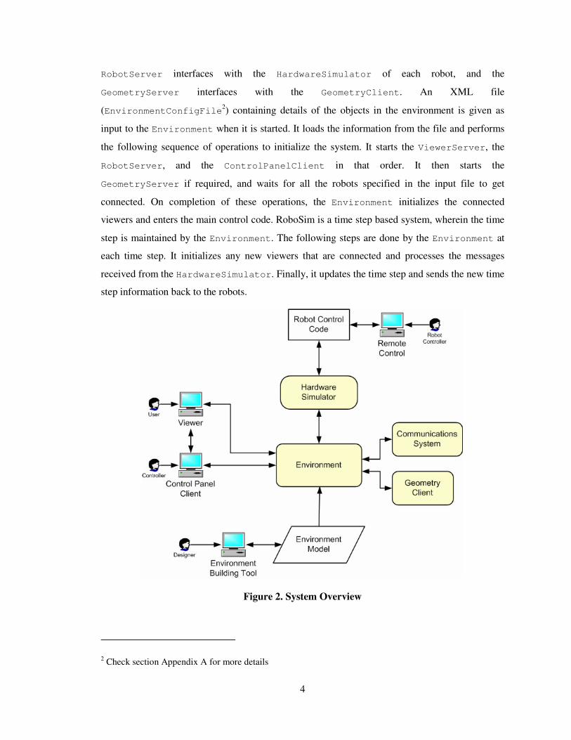
The diagram shown in Figure 2 shows the high-level overview of the whole system. The Remote
Control is used by the user to sends commands or requests to the Robot Control Code. The Robot
Control Code is the control code written on the robot for either communicating with the Remote
Control or functioning autonomously within the environment. This control code converts the
commands in to calls to the Robot Hardware Simulator. The Hardware Simulator sends the
requests to the Environment. The Environment module processes these requests
1.3 Scope and Objectives
The RoboSim system simulates the real world scenario of a group of robots aimed at achieving a
goal. The current system has a limited set of sensors that have been implemented. For a full-scale
simulation, the number of different types of sensors that are simulated should be increased.
Moreover, the user should have the ability of controlling the robots from a remote system. Hence,
this project aims at satisfying two primary goals. First is the simulation of three new sensors
namely, SONAR Range Finder, LASER Range Finder and the HEAT Sensor. These sensors
assist the robots in acquiring better knowledge concerning the environment and the objects
present in it. The second goal is the creation of a RemoteControl capability that can be used to
control robots from a remote location or system.
1.4 Document Overview
The document so far gives a basic overview of the entire system. In Chapter 2, a discussion about
similar research is done. In Chapters 3 and 4, the document moves on to discuss the
methodologies and implementation of the Sensor modules and the RemoteControl module
respectively. The discussion then shifts to the testing of the developed modules in Chapter 5
where the Maze application developed for testing the system is discussed in detail.
The final chapter presents a conclusion to the report and specifies the future enhancements and
changes that could be brought into the simulator with respect to the Sensor and Remote Control
modules. The appendix explains the steps for starting the application and operating it.

6
Chapter 2 Literature Review
2.1 Introduction
In recent years, Robotic Simulators have been a particular area of interest for a number of
researchers and developers. There have been many projects that are similar to the RoboSim
simulator. This chapter is aimed at discussing certain projects that fall in the same category of
RoboSim. This chapter provides a foundation for knowledge about similar research in the area of
Robotic Simulators.
2.2 Rossum – RP1 Simulator
Rossum [�4] is a robotic simulator project that is currently under development by a group of three
programmers at sourceforge.net. The Rossum’s project aims are building a client-server
based robotic simulator, which can be used for testing code that will be running on the original
robot. The first version of the project is named the RP1 simulator. It allows the users to create
robot models by specifying the physical layout, wheel actuators, optical (or IR) sensors, range
sensors, and bumper sensors. Internally, it represents the world as a 2D environment, and models
the interactions and movements in a 2D manner. Though it has not been currently implemented,
the ultimate aim of the geometric model will be a 3D representation. The simulator is written with
Java as the programming language. It provides the user with a server. The server provides a world
in which the simulated robot can move about and interact with its environment. Though the robot
is simulated by the server, it does not implement any navigational logic. It is the work of the
client program, which connects to the server, to provide the robot with navigational logic. The
client program is written by the user/developer who wants to test the code they will be running on
the actual robot. The environment provides information to the client such as bumper sensor
readings, IR sensor readings, etc. Based on these readings and any other information, that client
has, it issues commands, like ‘move forward’, to the simulator. One of the major advantages of
this system is that the client connecting to the server can be written in any language suitable to the
developer/user. Though the server is implemented in Java, it can communicate with a client
written in C, C++, Forth, Lisp, Prolog, even Basic. However, a major constraint in the current
release is that it can support only one client in a full-fledged manner, at any instant of time.

7
2.3 RoboCup – Soccer Simulator
RoboCup [�6] is a robotic simulator whose main goal is to simulate a soccer match played by
robots. The ultimate goal of the project is to develop a team of fully autonomous humanoid robots
that can win against the human world soccer champion team.
The main module of the system is the Soccerserver. The Soccerserver enables autonomous agents
consisting of programs written in various languages to play a match of soccer against each other.
A match is carried out in a client-server style. Soccerserver, provides a virtual field and simulates
all movements of a ball and players. Each client controls the movements of one player.
Communication between the server and each client is done via UDP/IP sockets. Therefore, users
can use any kind of programming systems to interface with the server.
The Soccerserver consists of two programs, Soccerserver and Soccermonitor. Soccerserver is a
server program that simulates movements of a ball and players, communicates with clients, and
controls the games according to rules. Soccermonitor is a program that displays the virtual field
from the Soccerserver on the monitor using the X windows system. A number of Soccermonitor
programs can connect with one Soccerserver, so it can display field-windows on multiple
windows.
A client connects with the soccer server using a UDP socket. Using the socket, the client sends
commands to control a player of the client and receives information from sensors of the player. In
other words, a client program is the brain of the player. The client receives visual and auditory
sensor information from the server, and sends control-commands to the server.
2.4 MobileSim
MobileSim [�8] is a simulator developed by ActivMedia Robotics Corporation, manufacturers of
the Pioneer class of robots. MobileSim simulates mobile robots and their environments, for
debugging and experimentation with Aria based control programs and other software. It converts
an ActivMedia map3 to a Stage environment, and places a simulated robot model in that
environment. It then provides a simulated Pioneer control connection accessible via TCP port
81014. Most Aria based programs will automatically connect to that TCP port if available.
MobileSim is based on the Stage library, created by the Player/Stage project [�9].
3 A .map file created by Mapper3 or Mapper3-Basic 4 Similar to real Pioneer’s serial port connection

8
The Player/Stage project [�9] consists of two modules namely the Player and the Stage. Player is a
networked robot/sensor device interface and Stage provides a 2D simulated world. Player
provides a clean and simple interface to the robot's sensors and actuators over the IP network. The
client program talks to Player over a TCP socket and reads data from sensors, writes commands
to actuators, and configures devices on the fly. Player supports a variety of robot hardware. The
original Player platform is the ActivMedia Pioneer 2 family, but several other robots and many
common sensors are supported.
Stage is responsible for providing a population of robots, sensors and objects within a 2-
dimentional environment. The development of Stage is based on multiagent systems. Since the
Stage provides a population of virtual devices to the Player, users can write robot controllers and
sensor algorithms as client programs to the Player server. Various sensors and actuators are
provided, including sonar, scanning laser rangefinders, vision (color blob detection), odometer,
and a differential steer robot base.

9
Chapter 3 Sensor Module Simulation
3.1 Introduction
One of the primary goals of this project was aimed at simulating the various sensors present on
the robots. These sensors are responsible for providing essential information about the
environment, which could be used by the robots to determine the state of the environment. By
determining the state relative to their current position in the environment, they issue the next best
possible move towards achieving their goal. Each robot is provided with set of sensors, which
varies based on the model of the robot. The Nomad Scout, and the ActivMedia Pioneer are the
two robots which have been implemented in the simulator. The Nomad Scout robot can have a
SONAR range finder and/or a HEAT sensor. The ActivMedia Pioneer has the option of having a
SONAR range finder, LASER range finder, and/or HEAT sensor. This chapter discusses the
simulation of a SONAR range finder, LASER range finder and HEAT sensor for the robots.
3.2 Sensor Modules – An Overview
The main classes in the Sensor module are the RobotSensor, RobotSensorLaser,
RobotSensorSonar and RobotSensorHeat. They are implemented as part of
edu.ksu.cis.cooprobot.simulator.environment package. Any new sensor class that is
implemented is derived from the RobotSensor class. This class comprises all the common
characteristics that are necessary for each sensor type. The RobotSensor has an abstract method
generateSensorResponse()that should be implemented in each sensor class that is derived
from it. This abstract method is used for obtaining the corresponding sensor response whenever
the robot requests it.
Figure 3. Sensor Modules - High Level Class Diagram
Figure 3 shows a high-level view of the sensors that have been implemented in this project. It
shows that the RobotSensorLaser, RobotSensorHeat, and RobotSensorSonar classes that

10
simulate the LASER, HEAT, and SONAR sensors respectively are derived from the
RobotSensor class. Each robot is associated with an instance of the corresponding class for
each sensor it carries. This instance is stored in the Environment. Since the position and
characteristics of all the objects are maintained and updated by the Environment, these classes
are implemented as a part of the edu.ksu.cis.cooprobot.simulator.environment
package and are invoked when the robots request for any of the sensor readings.
Figure 4. Sensor Module - Sequence Diagram
Figure 4 shows the sequence of events happening when a remote control object requests a sonar
sensor reading. The sequence of events happening will be similar in the case of the other sensors
too. These events are triggered when the RemoteControl or other application code requests for
the sensor readings. The RemoteControl sends a REQ_SONAR message to the
RemoteControlRobot. The RemoteControlRobot maintains a buffer of sensor readings and
hence, checks if the sensor readings are relative to the current time step, waits infinitely until the
sensor message buffer is updated by the HardwareSimulator. The HardwareSimulator
executes as a separate thread and periodically updates the sensor readings by sending requests to
the RobotClientWorker. On receiving the request from the HardwareSimulator, the
RobotClientWorker sends the set of sensor requests to the GeometryClientWorker. The
GeometryClientWorker obtains references of the robots from the Environment. These
references contain instances of the corresponding class for each sensor the robot contains. It calls

11
the generateSensorResponse() method of the corresponding sensor class and puts the
response into the queue of messages to be sent back to the RemoteControlRobot. The
RobotClientWorker obtains this queue of messages and sends it to the HardwareSimulator.
On receiving the sensor response, the doSensorUpdate() method of the
RemoteControlRobot is invoked. This method updates the sensor readings buffer and the
Boolean flags to indicate that the information has been updated. The RemoteControlRobot
waiting for the sensor reading, on return of a true from the isSensorNew() method, comes out
of the wait state and sends the requested sensor information to the RemoteControl or to the
application code. A similar sequence of events happens when a sensor request is obtained for the
Laser and Heat sensor readings.
3.3 Methodology
3.3.1 LASER Range Finder
The laser range finder is responsible for determining the distance and coordinate information of
an object that is in the line of sight of the direction in which the sensor is pointing and within its
maximum range. This is done by shooting a pulse in the direction in which it is pointing. Based
on the reflection of the laser from the face of an object, the distance of it and its coordinate
information is calculated. The Laser range finder is capable of rotating through an angle of 90
degrees on either side from the direction in which the robot is facing.
3.3.2 SONAR Range Finder
Each type of robot has a specific setup for the SONAR range finder. The SONAR that has been
simulated is done using the specifications of the Pioneer 3 model. The Pioneer 3 model may have
a total of either 8 or 16 array of sonar sensors. They are placed as one or two sets, based on the
number of sensors, thus forming the front and rear array of sonar sensors. If there are 8 sensors,
then only the front array is present, else if there are 16, then both the rear and front arrays are
present. These sonar sensors individually cover 20 degrees each and in turn scan a total angle of
360 degrees around the robot. Every time a reading is requested from the SONAR sensors, a
sonar pulse is sent from each of the SONAR, one at a time. Each sonar sensor in the array returns
the distance of the closest object in its sector and its x, y, and z coordinates relative to the robot.
Hence, 8 or 16 readings are sent back to the robot.

12
3.3.3 HEAT Sensor
The Scout and the Pioneer class of robots do not have an actual heat sensor available. This sensor
was mainly simulated in order to help in certain specific application like a search and rescue,
wherein the victims are identified based on the heat that is emitted from them. A detailed
description of the heat sensor is given in section �3.4.3.
Figure 5. Sensor Modules - Detailed Class Diagram

13
3.4 Implementation
3.4.1 LASER Range Finder
The RobotSensorLaser class simulates the Laser Range Finder. The attributes of the class are
shown in Figure 5. An instance of this class is created for each robot that has the laser sensor. The
parameters required for initializing the sensor are the direction5, range6, id (id of the
sensor), and xyz coordinates relative to the position of the robot are provided in the
EnvironmentConfigFile file supplied to the environment. The response of the laser is
calculated in the generateSensorResponse() method of the RobotSensorLaser class. The
GeometryClientWorker passes the updated information of the environment objects packed in
an EnvironmentMap object as a parameter to the generateSensorResponse() method.
There are two types of objects present in the environment, namely, cubes and cylinders. The
Laser sensor performs a 2D geometry based calculation. It uses the shapes made by the objects
against the horizontal XY plane. Hence the cubes and cylinders are considered as circles and
rectangles respectively.
Initially it calculates the absolute position of the sensor based on the position of the robot and the
xyz relative positions. In the second iteration, the method checks if the height of the object is
greater that the position of the sensor, to check if it is hit by the laser. In the next iteration, it
determines the point and distance of intersection of a horizontal line, drawn from the origin of the
laser in its pointing direction, with the object. The methods intersectLineCircle() and
intersectLineSquare() are used for calculating the intersection points with circles and
rectangles respectively. This process is repeated for all the objects and the closest objects
intersection point and distance is sent back to the environment. In case there are no objects within
the range of the Laser, it returns the maximum range of the laser. The return values are packed
in to a RobotSensorResponse class object.
3.4.2 SONAR Range Finder
The RobotSensorSonar class is responsible for simulating the Sonar Range Finder. The
attributes and methods of this class can be seen in Figure 5. The sensor object is created and it
5 Indicates the direction in which the laser is facing relative to the robot. It is stored in the attribute rot of the RobotSensor class. 6 Indicates the range within which the sensor can detect objects. It is stored in the attribute range of the RobotSensorLaser class.

14
parameters are loaded in a similar way as the Laser Range Finder. The parameters required for
initializing the sonar sensor are the range7, id (id of the sensor), and mode. The mode parameter
indicates if the robot has 8 (mode =1) or 16 (mode = 2) sensor array. The response of the SONAR
is determined in the generateSensorResponse() method of the RobotSensorSonar class.
Initially, the absolute position of the sonar sensors around the robot is determined. Using this
position as the origin, two lines showing the boundary of the sonar’s area of coverage is drawn.
Each environment object is verified against these two lines, if they lie in between them and within
the range. The sonar makes use of the intersectLineCircle() and
intersectLineSquare() for this purpose. This process is repeated for all the sonar sensors in
the array. The method finally returns the distance and point of intersection of the closest object in
each sonar sector. This information is packed in an object of the RobotSensorResponse class.
3.4.3 HEAT Sensor
The RobotSensorHeat class is responsible for simulating the HEAT sensor. A detailed view of
the class can be seen in Figure 5. The parameters for initializing the Heat sensor are the range
and id (id of the sensor). The range specifies the distance within which it is capable of sensing
heat. When a request for readings from the Heat sensor is requested for a robot, the control is
passed to the generateSensorResponse() method of the RobotSensorHeat class. Here, it
finds each environment object within the range of the sensor, checks if the object is generating
heat, if so a value, inversely proportional to the distance of the object from the sensor and directly
proportional to the temperature of the object, is added to the reading of the sensor. This is packed
in an instance of the RobotSensorResponse class and sent to the robot.
7 Indicates the range within which the sensor can detect objects. It is stored in the attribute range of the RobotSensorSonar class.

15
Chapter 4 Remote Control Simulation
4.1 Introduction
Apart from the simulation of the sensors, the other primary goal of this project was to create a
remote control that could be used for controlling the activities of the robot from a remote
machine. An additional feature that was to be integrated with the remote control was controlling
the movements of the robot using a joystick. The remote control, integrated with the joystick,
provides a means for the user to interact with the system. It acts as an interface between the user
and the robot, by accepting the movement instructions from the user and displaying the current
characteristics of the robot back to the user. The remote control could also be used for controlling
multiple robots at the same time. This chapter discusses in detail the simulation of the remote
control module.
4.2 Methodology
The remote control is responsible for obtaining inputs from the user by two ways. One is by using
a Graphical User Interface, which receives basic instructions like accelerate, decelerate, turn
right, turn left, and acquire various sensor readings. The other is by using a joystick, which the
user can operate in order to move the robot within the environment. In addition to receiving
inputs from the user, the remote control should also display the various sensor readings relative to
the current position of the robot. This can be done in a live manner, where in the information
displayed is updated whenever the position of the robot is changed, or in a request based manner,
where in sensor information is updated only when the user requests it. The implementation of the
remote control is discussed in the next section.
4.3 Implementation
The main classes in the Remote Control Module are the RemoteControl,
RemoteControlRobot and the RemoteControlMessage. They are implemented as a part of
the edu.ksu.cis.cooprobot.simulator.applications.maze package. The
RemoteControl class implements the remote control, waiting for input from the user. The
RemoteControlRobot class simulates the robot that is controlled by the remote control. The
RemoteControlRobot and RemoteControl use the RemoteControlMessage class for
exchanging control and sensor information between each other. Figure 6 gives a high-level view
of the remote control module. The functioning of the system can be explained in detail as follows.

16
For every robot controlled by the remote, the RobotConfigFile file should contain information
regarding the IP address of the RemoteControlRobot system and the port number at which it
will connect to the RemoteControl. This is given as input to the RemoteControl thread. The
RemoteControl implements the abstract class JoyStickListener8. It first initializes the
JoyStickListener and then it loads the information of all the robots and determines the
primary robot it will be controlling, identified using the tag primary in the RobotConfigFile.
Figure 6. RemoteControl Module - High Level Class Diagram
On loading the information of all the robots, the RemoteControl initializes and starts the
CRS3DViewer (a type of Viewer) thread. The CRS3DViewer is used for displaying 3D view of
the environment and its objects. The view shown will be relative to the robot. It will capture the
picture as that of a camera placed on top of the robot. This helps the user in navigating through
the environment. Therefore, the user can move the robot around the environment and request
sensor data even from a remote system. The effectiveness of the Viewer module was seen during
the testing phase when navigating through the Maze.
The RemoteControl and RemoteControlRobot use the RemoteControlMessage for
communication between each other. The types of messages that can be used for communication
are shown in Figure 7. They are the INIT, INIT_ACK, ACCELERATE, DECCELERATE,
TURN_LEFT, TURN_RIGHT, REQ_HEAT, REQ_LASER, and REQ_SONAR. The type of the message
8 JoystickListener [�10] is a vendor API which is used for receiving input from the joystick in a similar way to an ActionListener in Java.

17
is indicated by the attribute messageType of the class RemoteControlMessage. The INIT
message is sent when a connection is established. The INIT_ACK message is sent from the
RemoteControlRobot when it receives an INIT message and from the RemoteControl when
it wants to inform a robot to switch between executing autonomous control code and remote
control commands. The ACCELERATE, DECCELERATE, TURN_LEFT, and TURN_RIGHT are
messages representing movement commands sent by the RemoteControl. The REQ_HEAT,
REQ_LASER, and REQ_SONAR are messages which represent, sensor reading request if sent from
RemoteControl, and sensor reading replies if sent from RemoteControlRobot.
Figure 7. Remote Control - Robot Protocol Diagram
Figure 8 represents a detailed view of the classes of the Remote Control module. After starting
the Viewer thread, the RemoteControl waits for all the secondary robots to connect with it. As
soon as it connects to each secondary robot, it sends an ‘INIT’ message to it with the attribute
autonomous set to TRUE. On receiving the message, the secondary robots start executing the
autonomous control code9. Finally, the RemoteControl connects with the primary robot and
9 Autonomous control code is present in the autonomousControlCode() method of the RemoteControlRobot class.

18
sends an INIT message with the attribute autonomous set to FALSE. On receiving this, the
primary RemoteControlRobot is set to execute the remote control code10. The system now
enters the main loop, where the RemoteControl waits and receives commands from the user
and sends it to the primary robot. The primary robot then processes the requests and action
commands by sending it to the HardwareSimulator.
Figure 8. RemoteControl Module - Detailed Class Diagram
The user can change the primary robot controlled by the RemoteControl by clicking the
appropriate button11 in the joystick. When the user presses this button, the RemoteControl
sends an INIT_ACK message to the primary robot, sets it to execute the autonomous control
code, and puts it in the tail of the list of secondary robots. It then selects the first robot in the list
10 Remote control code is present in the remoteControlCode() method of the RemoteControlRobot class. 11 Refer to section �Appendix A for operation configuration of the application.

19
and sends an ‘INIT_ACK’ message to sets the selected robot to listen to the commands from the
RemoteControl.

20
Chapter 5 Testing & Results
5.1 Introduction
The modules that were developed were successfully integrated into the RoboSim. In order to test
the correct functioning of these modules, an application was developed which uses the
information obtained from these modules. This chapter discusses in detail the two versions of the
Maze application that was developed in order to test these sensor and the RemoteControl
modules.
5.2 Testing Sensor Module
5.2.1 Methodology
The Version 1 of the Maze application was used for testing the sensor modules. In this
application, a group of robots search through a large Maze for finding gold kept at an unknown
location. The robots move through the maze and find the gold by using their sensors and they
communicate with each other for passing information if the gold has been detected by any of the
robots.
5.2.2 Implementation
The GoldFinder class, derived from the Aria robot interface, simulates the gold finding robots.
The main loop of the GoldFinder can be seen in Figure 9. The robot gets the readings from the
SONAR and the HEAT sensors. The Gold class simulates the presence of gold inside the Maze.
It generates heat at a temperature specified in the XML file.
The HEAT sensor calculates the reading based on the temperature of objects within a specified
range. The robot checks the temperature obtained from the HEAT sensor against a threshold
temperature that identifies the Gold. As soon as it detects the presence of Gold, it sends a GOLD
message to its neighboring robot. The robots transfer messages in a cyclic manner. When the
application is started, for each robot, the robot to which it can send message is given as input.
Hence, when a message is to be sent across, it is sent to only one robot at a timestep. If a GOLD
message is received by any robot in the application, it sends a GOLD message with the source of
the message and information to its neighboring robot and halts at that point. Hence, the
application comes to a stop once any of the robots detect gold inside the Maze. In addition to the
SONAR and the HEAT sensor, the application also made use of the LASER sensor for navigation
inside the Maze. The readings that were obtained from the sensors at various locations in the

21
environment are displayed in Table 1. These readings were obtained for the
EnvironmentConfigFile OpHo2_1.xml. These readings were compared against manual
calculations and they were found to be consistent.
Figure 9. Maze Version 1 - Main Loop
Figure 10. Maze - Testing Sensor Module

22
Robot Position and Angle Sonar Readings
No. X Y Z � 1 2 3 4 5 6 7 8 9 10 11 12 13 14 15 16
Laser Readings
Heat Readings
1 -10 -89.5 5 90 6.5 8.3 12.4 16 16 16 16 16 16 11.1 8.3 7.5 7.5 8.3 8.3 6.5 13.6 0
2 -30.6 -85.7 5 170 11.9 13 16 16 16 16 16 11.6 11.4 12.3 16 16 16 16 16 12.1 21 0
3 -47.9 -82.7 5 170 8.8 9.8 13.3 16 16 16 16 14.6 14.5 16 16 16 16 16 13.3 9 21 0
4 -81.7 -72.9 5 150 16 16 16 16 16 16 16 16 16 16 16 16 16 16 9 12.1 17.9 0
5 -78.6 -40.6 5 70 5.1 16 16 16 16 16 16 16 16 16 16 16 16 16 10.2 5.8 21 0
6 -62 -35.3 5 330 12.8 16 16 16 16 16 16 16 16 16 16 16 16 16 16 7.1 21 0
7 17.4 -47.7 5 60 13.9 5.9 5.3 11.7 16 16 16 16 16 16 16 16 16 16 16 16 19.28 0
8 4.4 0 5 100 12.4 16 16 16 6 6.9 16 16 16 16 16 16 16 16 13.3 12.2 21 5.39
9 3.5 4.9 5 40 16 12.9 12.9 14.2 16 16 16 1.1 1.4 16 16 16 16 16 16 16 17.8 11.7
10 -1.1 15.7 5 170 16 16 16 16 16 16 16 0.8 1.3 16 16 16 16 16 16 16 15.6 12.2
Table 1. Sensor Data from application

23
5.3 Testing RemoteControl Module
5.3.1 Methodology
The Version 2 of the Maze application was used for testing the RemoteControl module of the
simulator. The application involves the controlling of robots by an external user by using the
joystick. The robots are placed within a maze and the ultimate goal of the user is to move the
robot within a suitable distance from the gold that is placed in the Maze. The first robot to reach
the gold is termed as the winner.
Figure 11. Maze - RemoteControl Module
5.3.2 Implementation
The RemoteControl class is responsible for receiving the joystick input from the user. It sends
the received requests and commands to the RemoteControlRobot instance that it controls. On
reaching within a close vicinity of gold, if the user requests to check for a win situation, the robot
sends a request to the environment, which determines if the user has won. If so, it sends the win
information to all the robots. On receiving this information, all robots are made to come to a halt.
The display of the RemoteControl can be seen in the Figure 11 below. The user moves through
the Maze by using the 3D display shown in Figure 11. The remote control was displayed at the
‘Spring Open House 2005’ at Kansas State University. The readings obtained from the sensors

24
were checked for consistency with the graphical display shown on the GUI. At various locations
in the maze, the sensor information obtained was found to be consistent with the readings derived
from manual calculations.

25
Chapter 6 Conclusion
The Sensor and RemoteControl modules were integrated with the environment and tested
using the two versions of the Maze application. The Version 2 of the Maze application was
displayed for user at the Open House 2005 event at Kansas State University.
The SONAR, LASER and HEAT sensors consistently provided accurate information, which was
used by the robot for navigation through the maze. The current system uses the 3D Sonar
simulator, present within the GeometryServer, for sensor readings for the robot.
The RemoteControl in the system is capable of receiving input from the user through a
Joystick, as well as the Graphical User Interface, for controlling the movements of the robot.
6.1 Future Enhancements
During the course of development of the project, there were some ideas that I thought could be
considered as future enhancements in the project. They are explained below.
In the current system, for sending back sensor responses to the robot, for each sensor request sent
by the robot, a sensor response packet is sent back to it. In future if all the sensor requests for a
particular robot at each timestep could be packaged together and sent, it will minimize the
network traffic between within the system. For this to be implemented, the
processSensorRequests() method of the Environment and the corresponding
doSensorUpdate() method of the HardwareSimulator should be modified appropriately.
The three sensors that have been simulated perform the operations based on perfect geometric
calculations. However on the real robot, the readings that are obtained from the sensors may be
corrupted and prone to errors. An example of one such error could be noise disturbance. Since the
simulator should behave in an exact manner as the original system, in future the sensor readings
that are sent from the sensors should be error prone and these errors should be introduced in a
calculated manner based on the real robot sensors.
The current RemoteControl interface was developed with the RemoteControlRobot
extending the ArRobot interface of the Pioneer robot class. Hence the remote control feature
is not available for the Scout robot interface, the Scout. In future, this feature should be extended
to the Scout robot’s interface too.

26
The code that is written on the simulator has not been tested on the actual robots. A significant
advancement in the simulator could be to solve the porting problems that will be faced when
using the code from the simulator on the actual robots.

27
REFERENCES
1. S.A. DeLoach, “Cooperative Robotic Simulator”, May 2005, http://www.cis.ksu.edu/~sdeloach/ai/projects/crsim.htm
2. S. Harmon, “Cooperative Robotic Simulator – Environment Simulator”, tech. report, Multiagent & Cooperative Robotic Laboratory, KSU, May 2004.
3. S. Harmon, “Cooperative Robotic Simulator”, June 2005, http://robosim.user.cis.ksu.edu/tiki-index.php
4. G. W. Lucas, “The AutoPilot Demo”, March 2005, http://rossum.sourceforge.net/.
5. G. W. Lucas, “Rossum’s Playhouse User’s Guide for Version 0.60”, January 2005, Sonalysts Inc.
6. O. Obst, “The RoboCup Soccer Simulator”, Nov 2003, http://sserver.sourceforge.net/.
7. M. Chen, E. Foroughi, F. Heintz, et. al, “Users Manual - RoboCup Soccer Server”, Aug 2002.
8. ActivMedia Robotics, “MobileSim”, April 2005, http://robots.activmedia.com/.
9. R. Vaughan, B. Gerkey, A. Howard, “The Player/Stage Project”, May 2005, http://playerstage.sourceforge.net.
10. George Rhoten, “JavaJoystick”, June 2005, http://javajoystick.sourceforge.net/

28
Appendix A Users Manual
RoboSim is a distributed system that can be run on network of systems. The simulator consists of
a minimum of four modules that need to be started. They are the Environment,
GeometryClient, 3D/2D Viewer, RemoteControlRobot, and RemoteControl started in
the given order. The detailed steps for running the simulator with the RemoteControl are
explained in this appendix.
A.1 Starting Simulator – With RemoteControl
The step-by-step procedure for starting the simulator is given as follows:
1. Check out the RoboSim project from the CVS repository. The CVS is located at the server
fingolfin.user.cis.ksu.edu12. A login is necessary to check out.
The RoboSim\scripts\ directory contains the executable files for Windows and Linux
based systems. They are written to load pre-defined environment configurations. Samples of
the EnvironmentConfigFile are located in the
RoboSim\TestLoadFiles\Environment directory (e.g. OpHo1.xml). The
RobotConfigFile given to the RemoteControl is also located in this directory (e.g.
RobotInfo.xml). Using these files as templates, you can create new files based on the
applications specifications.
The Environment is the first module that should be started. The file given as input is the
Environment configuration file. The command is:
start java edu.ksu.cis.cooprobot.simulator.environment.Environment
<EnvironmentConfigFile>
2. The next two modules to be started are the 2D/3D Viewer and the GeometryClient. They
can be started in any order using the following commands:
start java edu.ksu.cis.cooprobot.simulator.viewer.Viewer2D <EnvHostname>
<EnvWaitPort = 3000>
start java edu.ksu.cis.cooprobot.simulator.viewer.Viewer3D <EnvHostname>
<EnvWaitPort = 3000>
start java edu.ksu.cis.cooprobot.simulator.geometry.GeometryClient
<EnvHostname> <EnvWaitPort = 10000>
12 Server will be moved to macr.user.cis.ksu.edu in future

29
In the previous commands shown, the EnvHostname is the hostname or IP address of the
system in which Environment module is running and EnvWaitPort is the port at which the
Environment is waiting for a connection with the corresponding module.
3. The RemoteControlRobot module is the next one to be started. It can be done using the
following command:
start java edu.ksu.cis.cooprobot.simulator.applications.maze.RemoteControlRobot 0
<EnvHostname> <EnvWaitPort = 8000> <No. of sonars> <x-pos> <y-pos> <RCPort>
In the previous command, the EnvHostname and EnvWaitPort represent the same as
mentioned in step 4. The next input is the size of sonar sensor array present in the robot. The
x-pos and y-pos are the starting x and y coordinates of the robot. They can be used in
future for any mapping applications. The RCPort is the port at which the
RemoteControlRobot will be waiting for a socket connection from the RemoteControl.
4. Finally the RemoteControl is started using the following command:
start java edu.ksu.cis.cooprobot.simulator.applications.maze.RemoteControl
<RobotConfigFile> <EnvHostname>
In the above command, the RobotConfigFile is the configuration file containing the
information about the robots that will be controlled by the RemoteControl. The
EnvHostname is the hostname of the system in which the Environment is running.
A.2 Configuration File Formats
Figure 12. RobotConfigFile Format
Figure 12 shows the general format of a RobotConfigFile given as input to the
RemoteControl. The information that should be specified in the file are the Hostname/IP
Address of the RemoteControlRobot system, the Port at which the RemoteControl
connects to it, the Robot – Name and a ‘1’ to indicate this robot is primary else a ‘0’. Only one
RemoteControlRobot specified in the file can have a ‘1’ value in the primary tag.
<?xml version="1.0"?> <RobotInfo> <robot> <hostname><IP Address></hostname> <port><RCPort></port> <name><Robot Name></name> <primary><1/0></primary> </robot> … </RobotInfo>

30
Figure 13. EnvironmentConfigFile Example
Figure 13 shows an example for the EnvironmentConfigFile. This particular example contains the
information about a robot named Gold1, facing an initial angle of 0.0radians at location (10,-90,5)
with a radius of 3units, a height of 10 units, temperature of 0 degrees and is not stationary. It has
a laser range finder with ID = 3, RANGE = 20, the position relative to the robot is (1.5, 0, 3). The
<?xml version="1.0"?> <world> <surface> <type>smooth</type> <size> <xmin>-500</xmin> <xmax>500</xmax> <ymin>-500</ymin> <ymax>500</ymax> </size>
<object> <shape> <robot> <cylinder> <direction>0.0</direction> <name>Gold1</name> <x>30.0</x> <y>0.0</y> <z>0.0</z> <radius>10.0</radius> <height>1.0</height> <color>1.0 1.0 1.0</color> <hot>0</hot> <stationary>0</stationary> </cylinder> <sensor> <id>1</id> <type>heat</type> <range>15</range> </sensor> <sensor> <id>2</id> <type>sonar</type> <mode>2</mode> <position> <x-relative>1.5</x-relative> <y-relative>0.0</y-relative> <z-relative>3.0</z-relative> <range>15</range> </position> </sensor> <sensor> <id>3</id> <type>laser</type> <position> <x-relative>1.5</x-relative> <y-relative>0.0</y-relative> <z-relative>3.0</z-relative> <dir-relative>0.0</dir-relative> <range>20</range> </position> </sensor> </robot> </shape> </object> </surface> </world>

31
parameters for the stationary objects are also specified in a similar manner, but sensor section will
not be present and the tag <robot> will be replaced by <primative> and a value of 1 for the
<stationary> tag.
A.3 Controlling Buttons on Joystick
The Joystick buttons that are used for controlling the robot motions and their corresponding
actions are:
BUTTON 2 - Send CheckWin message to Environment
BUTTON 3 - Accelerate the robot
BUTTON 4 - Decelerate the robot
Joystick Handle moved left - Turn the robot left
Joystick Handle moved right - Turn the robot right

32
Appendix B Programmers Manual
This appendix discusses the information required for modifying the modules developed for this
report. It addresses the programmer’s point of view of the system developed.
B.1 Sensor Module
The Sensor classes that have been implemented are a part of the
edu.ksu.cis.cooprobot.simulator.environment package. The main logic of the sensor
is implemented in the generateSensorResponse() method of each sensor class. The
parameters of the sensors are loaded in the EnvironmentFileLoader class. If any new sensors
are added to the system or the current ones are modified, these issues have to be taken into
consideration.
B.2 RemoteControl Module
The RemoteControl, RemoteControlRobot, and RemoteControlMessage classes make up
the module. They are implemented as a part of the
edu.ksu.cis.cooprobot.simulator.applications.maze package. Any additional
commands that are to be used to control the robot can be implemented by modifying the protocol
existing between the RemoteControl and the RemoteControlRobot. If any new application
are developed, which require the robot to function in either of Autonomous or RemoteControl
mode, can be implemented by adding autonomous control code to the
autonomousControlCode() method and the remote control code to the
remoteControlCode() method of the RemoteControlRobot class.