REPORT: T020548-A1
39
REPORT: T020548-A1 Brigil Construction Geotechnical Preliminary Investigation - Tower B Highway 174 and Trim Road Orleans, Ontario August 13, 2013
Transcript of REPORT: T020548-A1

REPORT: T020548-A1 Brigil Construction Geotechnical Preliminary Investigation - Tower B Highway 174 and Trim Road Orleans, Ontario
August 13, 2013

Ottawa, August 13, 2013 Mr. Michel Gagnon Brigil Construction 500 Boulevard Greber Gatineau, Quebec J8T 7W3 Subject: Geotechnical Preliminary Investigation
(T020548-A1) Tower B, Highway 174 and Trim Road Ottawa, Ontario
Dear Mr. Gagnon: In accordance with your recent instructions, Inspec-Sol Inc. (Inspec-Sol) has carried out an update of the report previously submitted and is entitled a Geotechnical Preliminary Investigation for the above-mentioned site. It is considered preliminary until design drawings are further advanced and interaction with the client’s designers is completed. Such interaction may result in further investigation requirements. We thank you for having retained Inspec-Sol for technical and professional services and we hope to have the privilege of serving you again in the future. The Inspec-Sol team is committed to exceeding the expectations of its clients. Do not hesitate to contact us for any further information. Best regards. INSPEC-SOL INC.
Joseph B. Bennett, P. Eng. Vice-President JBB/vl

BRIGIL CONSTRUCTION
TOWER B
HIGHWAY 174 AND TRIM ROAD ORLEANS, ONTARIO
Date : August 13, 2013 Our Ref. : T020548-A1
BRIGIL CONSTRUCTION 500 Boulevard Greber
Gatineau, Quebec J8T 7W3
Geotechnical Preliminary Investigation Tower B
Highway 174 and Trim Road Ottawa, Ontario
O/Ref. : T020548-A1 August 13, 2013
Prepared by :
Joseph B. Bennett, P. Eng.
Approved by :
Renato Pasqualoni, P. Eng.
Distribution : Mr. Gagnon, Brigil Construction (Copy by e-mail: [email protected] and by mail) (In duplicate)

Respect for the environment and the preservation of our natural resources are priorities for Inspec-Sol Inc. With this in mind, we print our documents double-sided on 50 % recycled paper.

TABLE OF CONTENTS
1.0 INTRODUCTION...........................................................................................................1
2.0 SITE DESCRIPTION.....................................................................................................2
3.0 METHODS OF INVESTIGATION..................................................................................2
3.1 FIELD PROCEDURES ....................................................................................................2
4.0 SUBSOIL CONDITIONS...............................................................................................3
5.0 GROUNDWATER CONDITIONS..................................................................................3
6.0 DISCUSSION AND RECOMMENDATIONS.................................................................4
6.1 DESCRIPTION OF PROJECT ..........................................................................................4 6.2 SITE PREPARATION & DRAINAGE..................................................................................5 6.3 FOUNDATIONS .............................................................................................................6
6.3.1 Pile Foundations .................................................................................................7 6.3.2 Footings..............................................................................................................8
6.4 EARTHQUAKE CONSIDERATIONS ..................................................................................9 6.5 FLOOR SLABS..............................................................................................................9 6.6 DRAINAGE CONSIDERATIONS .....................................................................................10 6.7 LATERAL EARTH PRESSURES.....................................................................................10
6.7.1 Static Conditions...............................................................................................11 6.7.2 Dynamic Conditions..........................................................................................11
6.8 BUILDING BACKFILL ...................................................................................................12 6.8.1 Engineered Fill..................................................................................................12 6.8.2 Exterior Foundation Wall Backfill ......................................................................13
6.9 FLOOR SLABS............................................................................................................14 6.10 UNDERGROUND SERVICES .....................................................................................14
6.10.1 Bedding and Cover ...........................................................................................14 6.10.2 Service Trench Backfill .....................................................................................15
6.11 PAVEMENT SECTIONS ............................................................................................16 6.8 EXCAVATIONS AND GROUNDWATER............................................................................17
7.0 CONSTRUCTION FIELD REVIEW.............................................................................18
8.0 LIMITATION OF THE INVESTIGATION.....................................................................19
TABLE OF CONTENTS (CONT’D)
Tables Table I: Groundwater Levels Pg. 4
Table II: Recommended Pavement Structures Pg. 16
Drawings Site Location Map Dwg. No. T020548-A1-1
Borehole Location Plan Dwg. No. T020548-A1-2
Earth Pressure On Basement Walls Dwg. No. T020548-A1-3
Enclosures Borehole Logs Enclosures No.1 – 3
Appendix A Notes on Borehole and Test Pits
Geotechnical Investigation; Tower B; Hwy 417 and Trim Road, Ottawa ON 1 Ref. No. : T020548-A1 August 13, 2013
1.0 INTRODUCTION
Inspec-Sol Inc. (Inspec-Sol) was retained by Brigil Construction to undertake a Geotechnical
investigation for a proposed highrise development to be located at Highway 174 and Trim
Road, in the Town of Cumberland, Ontario. A Site location map is attached (Dwg. No.
T020548-A1). The authorization to proceed with the work was provided by Mr. Michel
Gagnon, acting as the representative for Brigil Construction.
The development Site is a vacant property, located on the north side of Highway 174 and to
the east of Trim Road. The Site is located on a flat plateau, which slopes downward to the
Ottawa River at its northern boundary. The proposed development consists of many multi-
story towers of which one (Tower A) is already constructed and occupied.
The proposed development, named as Tower B, will be located immediately adjacent to the
east of Tower A and will include a 15-storey high rise apartment building with two basement
levels. The basement will be to accommodate an underground parking garage that is
planned to have a larger footprint than the tower portion of the building.
The purpose of the geotechnical investigation completed in 2008 was to:
i) Determine the subsoil and groundwater conditions at three borehole locations;
ii) Review the subsoil and bedrock data, including that available from previous
investigations performed at the Site by Fondex Ontario Ltd. (Reference No. F2166,
F2739);
ii) Determine the soil profile depth to bedrock; or 30 m maximum;
iv) Provide recommendations for the design of the foundations; and
v) Comment on the geotechnical considerations relating to the design and construction
of this project.
The following report has been prepared to address the above noted terms of reference, with
the understanding that the design of the project will be carried out in accordance with all
applicable codes and standards. Any changes to the project described will require a review
by Inspec-Sol.

2 Geotechnical Investigation; Tower B; Hwy 417 and Trim Road, Ottawa Ontario Ref. No. : T020548-A1 August 13, 2013
2.0 Site Description
The investigated site is located to the east of Phase I (Tower A) within the greater property that
is known as Petrie’s Landing. Tower A was constructed and is operating as a residential
highrise. The site was a flat grassed field with a gentle slope to the north where it abuts the
slope embankment that grades down to the Ottawa River. The adjacent construction of Tower
A has deposited some soil stockpiles on the site for Tower B. Access to the site is from the
North Service Road that intersects Trim Road just north of Highway 174.
The location of the Site is shown on the Site Location Map, Dwg. No. T020548-A1-1.
3.0 METHODS OF INVESTIGATION
3.1 Field Procedures
The site work consisted of drilling a series of three (3) boreholes, one (1) to 12 m and two (2) to
bedrock. The holes were then surveyed into location and elevations were taken for ground
level relative to a geodetic benchmark. Monitoring wells were installed in the boreholes and
were monitored for water level. A hydraulic conductivity test was undertaken to provide
information regarding volume of groundwater. The scope of the field program was established
by Inspec-Sol.
The locations of the boreholes are shown on the enclosed Borehole Location Plan, Drawing
No. T020548-A1-2, while a complete description of the stratigraphy encountered at each test
location, is presented on the Borehole Logs, Enclosure Nos. 1 to 3.
The boreholes were carried out by means of an auger-equipped drill rig, mounted on an all-
terrain track vehicle, which was able to secure soil samples at regular intervals with a 50 mm
diameter standard split-spoon sampler.
Sampling procedures were performed in general accordance with ASTM Standard D-1586,
which provides the penetration resistance ("N-Value") of the soils. In-situ vane shear tests
were also performed for the most part because of the cohesive soils.
Additional information regarding the procedures of in-situ testing, as well as information
concerning the borehole logs, may be found in the Notes for Borehole Logs, Appendix ‘A’. All
recovered soil samples were returned to our laboratory for confirmation evaluation for
presentation purposes in this report. Laboratory testing was carried out on selected samples to
Geotechnical Investigation; Tower B; Hwy 417 and Trim Road, Ottawa ON 3 Ref. No. : T020548-A1 August 13, 2013
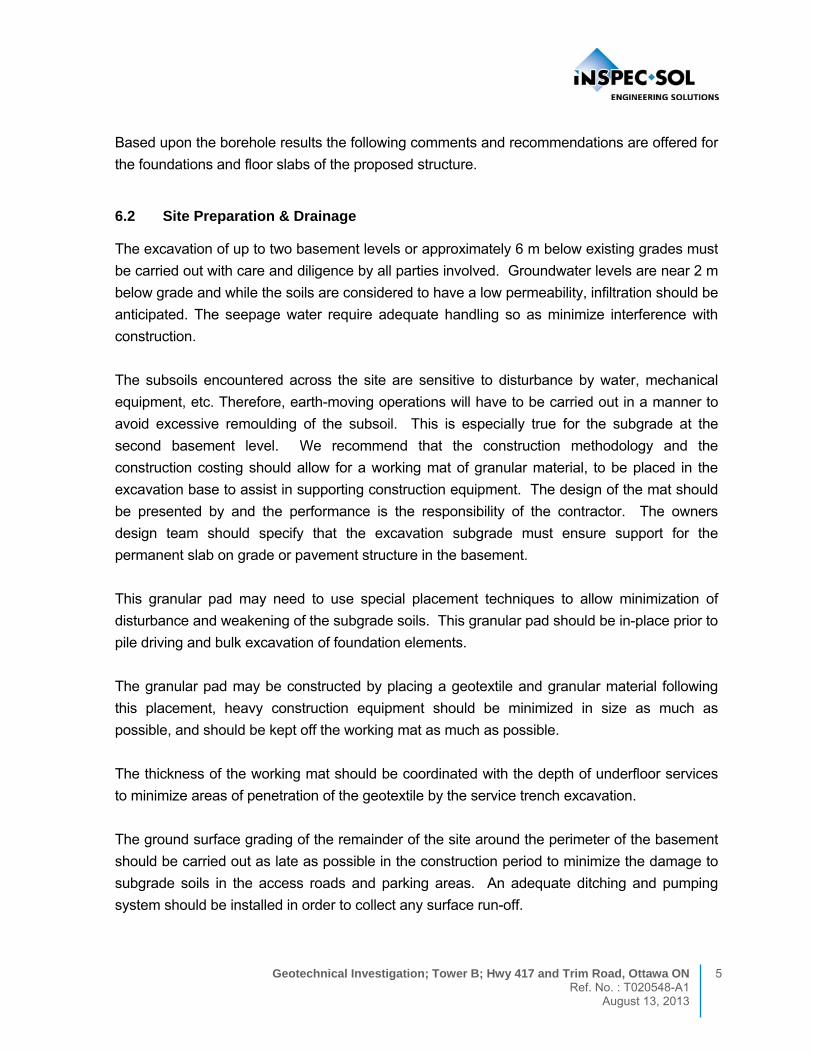
determine moisture content, as well as Atterberg Limits. These samples will be stored for a
three-month period, unless otherwise directed.
Ground surface elevations were taken at the test locations and were related to a site
benchmark, which was the floor slab of the Tower A site and had an elevation of 56.84 m. The
fieldwork was executed over the period of October 9 when the drilling was started and water
levels were recorded up to November 21, 2008 under the supervision of members of our
technical staff.
4.0 Subsoil Conditions
The subsoil at the Site, generally, consists of a 200 mm thick layer of topsoil overlying a
deposit of silty clay, which extends to down to bedrock found at a depth of about 25 to 26 m.
The silty clay has a very stiff, brown and desiccated crust extending to a depth of about 2.5
to 3 m, below ground surface. Below the stiff crust the clay weakens slightly and becomes
stiff, grey and wet to about 8m below which the deposit becomes stiffer. The silty clay was
found to be overlying bedrock.
The bedrock at the Site area is grey limestone of the Ottawa Formation. The depth to
bedrock, as determined based on rock coring, ranged from approximately 25 m to 26 m.
The subsoil and groundwater conditions encountered in each borehole are described in
detail on the borehole logs, Enclosures No. 1 to No. 3, inclusive.
5.0 GROUNDWATER CONDITIONS
The groundwater level was based on measurements within the borehole monitor wells. The
water levels were found to be near 1 m to 2 m below existing grades.

4 Geotechnical Investigation; Tower B; Hwy 417 and Trim Road, Ottawa Ontario Ref. No. : T020548-A1 August 13, 2013
TABLE I: GROUNDWATER LEVELS
Depth (elev.)
Date Date
Borehole
ID
Oct 31/08 Nov 20/08
BH1 1.7
(52.4)
1.5
(52.6)
BH2 0.8
(53.7)
0.7
(53.8)
BH3 1.9
(53.4
1.0
(54.3)
The groundwater levels will fluctuate seasonally and will be at the highest level during the
spring thaw. We suggest that for design purposes the high water table be considered to be
near the ground surface.
6.0 DISCUSSION AND RECOMMENDATIONS
6.1 Description of Project
It is understood that the proposed structure will consist of a 15-story tower with two levels of
basement level to be used for underground parking. The footprint of the parking garage will be
larger than the footprint for the tower. The floor slab will consist of a lightly loaded slab-on-
grade constructed at the lowest level.
It is important that the surrounding grades be kept within 0.75 m of the existing ground surface
levels. If higher grade changes are required then Inspec-Sol must be informed as grade raises
can lead to consolidation of the soils. If this occurs near pile foundations then negative skin
friction may result leading to higher pile capacity requirements. Also, shallow foundations may
also be subjected to intolerable settlements. These concerns of settlement caused by the
increased loading on the underlying soils require further engineering studies to assess the
degree of settlement and possible engineering solutions.
It is important that stockpiling of soils near the existing or near the new building basement walls
once they are constructed not be allowed since the loading and consolidation settlement
caused by the stockpiles may affect the existing or new building performance
Geotechnical Investigation; Tower B; Hwy 417 and Trim Road, Ottawa ON 5 Ref. No. : T020548-A1 August 13, 2013
Based upon the borehole results the following comments and recommendations are offered for
the foundations and floor slabs of the proposed structure.
6.2 Site Preparation & Drainage
The excavation of up to two basement levels or approximately 6 m below existing grades must
be carried out with care and diligence by all parties involved. Groundwater levels are near 2 m
below grade and while the soils are considered to have a low permeability, infiltration should be
anticipated. The seepage water require adequate handling so as minimize interference with
construction.
The subsoils encountered across the site are sensitive to disturbance by water, mechanical
equipment, etc. Therefore, earth-moving operations will have to be carried out in a manner to
avoid excessive remoulding of the subsoil. This is especially true for the subgrade at the
second basement level. We recommend that the construction methodology and the
construction costing should allow for a working mat of granular material, to be placed in the
excavation base to assist in supporting construction equipment. The design of the mat should
be presented by and the performance is the responsibility of the contractor. The owners
design team should specify that the excavation subgrade must ensure support for the
permanent slab on grade or pavement structure in the basement.
This granular pad may need to use special placement techniques to allow minimization of
disturbance and weakening of the subgrade soils. This granular pad should be in-place prior to
pile driving and bulk excavation of foundation elements.
The granular pad may be constructed by placing a geotextile and granular material following
this placement, heavy construction equipment should be minimized in size as much as
possible, and should be kept off the working mat as much as possible.
The thickness of the working mat should be coordinated with the depth of underfloor services
to minimize areas of penetration of the geotextile by the service trench excavation.
The ground surface grading of the remainder of the site around the perimeter of the basement
should be carried out as late as possible in the construction period to minimize the damage to
subgrade soils in the access roads and parking areas. An adequate ditching and pumping
system should be installed in order to collect any surface run-off.

6 Geotechnical Investigation; Tower B; Hwy 417 and Trim Road, Ottawa Ontario Ref. No. : T020548-A1 August 13, 2013
Soils and groundwater should be handled, transported and disposed of in an environmentally
suitable manner, meeting current environmental legislation.
The side slopes of the excavation should be able to be open cut sloped excavations. The
actual slopes should be verified by the contractor and a geotechnical consultant to ensure
their stablility. The slopes should be protected from weathering with tarps. The slopes may
require maintenance and backsloping over the life of the construction period, if erosion or
undercutting occurs. The alternative to open cut slopes is engineered shoring systems.
The west side of the excavation, where it will be near the existing building, must not
undermine any existing shallow and spread footings. If footings will exist at different levels
then the options to consider are (1) the existing footings can be underpinned; or (2) a
positive, stiff shoring system can be installed to support the footings and soils along this side.
The permanent foundation wall will need to be designed to support the lateral load
component from these footings. In this case also, the design and construction must prevent
a change in moisture conditions along this side that may lead to drying out and shrinkage of
the soils that would lead to settlement of footings. It may be necessary to waterproof the wall
and delete the perimeter drainage along this side.
The alternative is to create a smaller footprint in the second basement level by shifting the
lower foundation level to the east.
Inspec-Sol should be retained to review design and construction details for this area, to
ensure all geotechnical issues are addressed.
It is also important to consider in construction scheduling that piling options be completed
first prior to any loads being imposed on shallow and spread footings that will be newly
constructed. In addition, the contractors must ensure that piling operations are completed in
a manner to minimize vibrations and potential impact of vibrations to the existing Tower A
foundation systems. A vibration and monitoring plan should be submitted by the contractor
to the owner for the review by the design team.
6.3 Foundations
Based on the subsoil data, it is recommended that the proposed highrise building be
supported on end bearing piles, similar to Tower A.

Geotechnical Investigation; Tower B; Hwy 417 and Trim Road, Ottawa ON 7 Ref. No. : T020548-A1 August 13, 2013
The new building codes require buildings to be designed using limit states design values of
ultimate limit states (ULS) and serviceability limit states (SLS).
6.3.1 Pile Foundations
With the high column loads associated with this project, it will be necessary to support the
building structure on the bedrock, using piles. It is anticipated that concrete filled steel tube
piles will provide the most cost effective piling support system for this project. Steel tube
piles, having a diameter of 244 mm, typically carry loads in the order of 1200 kN per pile as
the SLS or allowable value. Because the piles are being driving to bedrock, which virtually
results in Nil settlements, the Ultimate Limit States resistant value may equivalent to the
structural capacity of the pile.
For estimating purposes, it is suggested that pile refusal be considered to occur within the
bedrock formation, which is indicated on the borehole logs which occurs near depths of 25 to
26 m approximately or elevation 29.3 m to 29.8 m approximately.
It is recommended that Pile Driving Analysis (PDA) be performed at the start of pile driving to
confirm the refusal criteria established for this project. Additional testing will be required as
the pile driving progresses. PDA testing is recommended for the initial 10% and then at
intervals for at least every 100 piles and/or at 50% completion unless problems with piling
are encountered, in which case additional testing may be required.
Re-striking of the piles is recommended at the start of piling, to ensure that pile capacities
are being maintained. Subject to satisfactory results, re-striking of piles is envisaged to be
carried out on a random basis, unless their capacity is suspect, or unless previously driven
piles have moved during the placement of adjacent piles. The initial PDA testing should
confirm the re-striking requirements.
Pile uplift capacity
The uplift capacity of for earthquake design purposes may be based upon rock anchors
drilled and anchored into bedrock or based on factored capacities at ultimate limit states and
capacities at serviceability limit states of the pile friction within the soil.
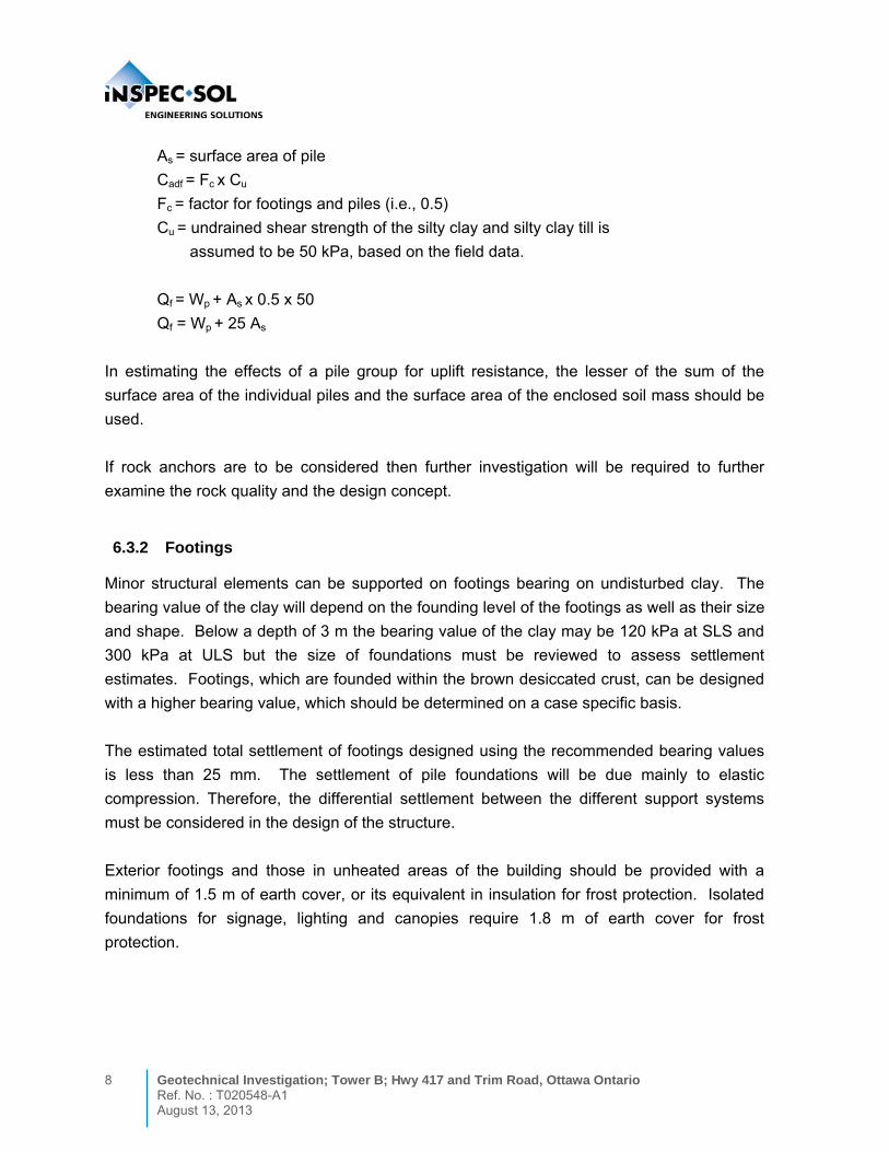
Qf = Wp + As Cadf
where;
Qf = factored uplift capacity
Wp = buoyant weight of pile
8 Geotechnical Investigation; Tower B; Hwy 417 and Trim Road, Ottawa Ontario Ref. No. : T020548-A1 August 13, 2013
As = surface area of pile
Cadf = Fc x Cu
Fc = factor for footings and piles (i.e., 0.5)
Cu = undrained shear strength of the silty clay and silty clay till is
assumed to be 50 kPa, based on the field data.
Qf = Wp + As x 0.5 x 50
Qf = Wp + 25 As
In estimating the effects of a pile group for uplift resistance, the lesser of the sum of the
surface area of the individual piles and the surface area of the enclosed soil mass should be
used.
If rock anchors are to be considered then further investigation will be required to further
examine the rock quality and the design concept.
6.3.2 Footings
Minor structural elements can be supported on footings bearing on undisturbed clay. The
bearing value of the clay will depend on the founding level of the footings as well as their size
and shape. Below a depth of 3 m the bearing value of the clay may be 120 kPa at SLS and
300 kPa at ULS but the size of foundations must be reviewed to assess settlement
estimates. Footings, which are founded within the brown desiccated crust, can be designed
with a higher bearing value, which should be determined on a case specific basis.
The estimated total settlement of footings designed using the recommended bearing values
is less than 25 mm. The settlement of pile foundations will be due mainly to elastic
compression. Therefore, the differential settlement between the different support systems
must be considered in the design of the structure.
Exterior footings and those in unheated areas of the building should be provided with a
minimum of 1.5 m of earth cover, or its equivalent in insulation for frost protection. Isolated
foundations for signage, lighting and canopies require 1.8 m of earth cover for frost
protection.

Geotechnical Investigation; Tower B; Hwy 417 and Trim Road, Ottawa ON 9 Ref. No. : T020548-A1 August 13, 2013
6.4 Earthquake Considerations
The clay has a very stiff desiccated crust extending to a depth of 3 m below which level it
becomes firm to stiff. Buildings and their foundations must be designed to resist a minimum
lateral earthquake force as defined by the Ontario Building Code, 2006. The site
classification for seismic site response was determined using the shear strength profile of the
clay and the limestone bedrock in accordance with commentary ‘J’ sentence 4.1.8.4 (3). The
average normalized shear strength for 30 m depth below the second level basement was
determined to exceed 100 kPa. Therefore, the Site Class is ‘C’. The calculations of Site
Class are provided below.
Liquefaction is not considered to be possible with the cohesive soil existing at the Site.
As per Commentary J of the Ontario Building Code based upon the following formula:
Su = total soil oveburden depth………
∑ layer thickness
Cu of layer
144
1000
11
150
5
100
9
75
3
60
230
Su
6.5 Floor Slabs
Slab-on-grade construction of the floor is anticipated at this Site.
Floor slabs may be designed as conventional slab-on-grade but will require field verification
by visual reviews during construction. Preparation of the area would require preparation of
the subgrade followed immediately by placement of filter cloth and covered with the granular
working mat. It is recommended that the floor slab be poured on a minimum of 200 mm of
Granular ‘A’ levelling layer.
It is recommended that vapour barriers be incorporated beneath the slab if floor coverings /
finishes of impermeable or low permeable type and / or where adhesive products are used.
The contractors must account for the impact of such on concrete placement and curing of the
slab. If the lowest basement level is used for car parking then this may not be required.

10 Geotechnical Investigation; Tower B; Hwy 417 and Trim Road, Ottawa Ontario Ref. No. : T020548-A1 August 13, 2013
Floor toppings may be impacted by curing and moisture conditions of the concrete. Floor
finish manufacturer’s specifications and requirements should be consulted.
The slabs should be free floating, and should not be tied into the foundation walls or grade
beams. The placement of construction and control joints in the concrete should be in
accordance with generally accepted practice.
6.6 Drainage Considerations
Under floor drains and perimeter drains are considered necessary for this structure since the
lowest basement level will be penetrating approximately 4 to 5 m below the water table. The
soils are considered a low permeable soil. Hydraulic testing completed in the wells on site
show that the soil permeability range is in the order of 10-6cm/sec to 10-7cm/sec. Therefore,
normal sized sump pits are envisaged for this project.
As described earlier, the west side adjacent to the existing parking garage structure should
not have perimeter drainage in order to prevent dewatering of the clay below the existing
footings of the parking garage structure.
6.7 Lateral Earth Pressures
Basement walls with soil backfill are to be considered as retaining walls and should be
designed to withstand lateral earth pressures. The bedrock is typically self supporting and
does not impact loads onto basement walls. If granular materials are placed between soil
and poured concrete walls then the walls should be designed for lateral pressures resulting
from the following sources:
Unit weight of the backfilled soil;
Temporary and permanent vertical loads on the completed ground surface; and
Lateral loads due to backfill compaction equipment.
If walls are poured directly against bedrock than the peak soil pressure is recommended to
be extended down to the bottom of the wall to result in a trapezoid pressure distribution.

Geotechnical Investigation; Tower B; Hwy 417 and Trim Road, Ottawa ON 11 Ref. No. : T020548-A1 August 13, 2013
6.7.1 Static Conditions
Under static conditions, the lateral active earth pressure acting on basement walls that are
restrained at the top are recommended to be estimated using a earth pressure coefficient of
K = 0.50, and no hydrostatic pressure distribution. This is based on the assumption that
there is a perimeter drainage system installed at the base of the wall to prevent the build-up
of hydrostatic pressure. The configuration of the earth pressure diagram is shown on the
drawing Earth Pressure on Basement Walls in Appendix E
6.7.2 Dynamic Conditions
For a seismic event, the Mononobe-Okabe equations, shown in Section 24.9 of CFEM-2006
are recommended. In these formulas, there are both geotechnical and geometric
components. The geotechnical parameters of imported granular backfill will be the following:
Unit Weight of Soil – 20.5 kN/m3 (assumes a weeping tile system is installed);
Internal Friction Angle - 35º;
kh = (PGA) - PGA is 0.42 for this area; and
kv = typically a range of 2/3 x kh to 1/3 kh is considered but a value closer to 2/3 x kh is
recommended.
The total active thrust under seismic loading (Pae) is recommended to be expressed as
follows:
Pae = ½ Kaeγ H2 x (1- kv)
This includes both the active pressures under static (Pa) as well as the increased force due to
seismic or simply as follows:
Pa = ½ Kγ H2
Therefore, the seismic force (Pe) is simply the difference between the Pae and Pa, or:
Pe = Pae – Pa

12 Geotechnical Investigation; Tower B; Hwy 417 and Trim Road, Ottawa Ontario Ref. No. : T020548-A1 August 13, 2013
The active force under static conditions is assumed to act at a point of (0.3 x H) above the
base and the seismic force is assumed to act near (0.6 x H) above the base, where H is the
height of the wall. Therefore the point of applying Pae may be calculated from the following:
h = [(0.33Hx Pa) + ( 0.6H x Pe)]/ Pae
In reducing the above formula for this site, we recommend values of Kae x (1-kv) = 0.7 and
K = 0.31. This condition applies for open cut excavations and granular backfill behind the
walls, assuming there is a weeping tile system and that walls are treated as being restrained.
6.8 Building Backfill
The placement and compaction of the materials that will support the floor slabs, or pavement
must be treated as Engineered Fill. Compaction equipment must be of size and distance
away to prevent damage to the walls during the time of placement.
6.8.1 Engineered Fill
The fill operations for Engineered Fill must satisfy the following criteria.
Engineered Fill must be placed under the continuous supervision of the Geotechnical
Engineer. Prior to placing any Engineered Fill, all unsuitable fill materials must be
removed, and the subgrade proof rolled, and approved. Any deficient areas should
be repaired;
Prior to the placement of Engineered Fill, the source or borrow areas for the
Engineered Fill must be evaluated for its suitability. Samples of proposed fill material
must be provided to the Geotechnical Engineer and tested in the geotechnical
laboratory for Standard Proctor Maximum Dry Density (SPMDD) and grain size, prior
to approval of the material for use as Engineered Fill. The Engineered Fill must
consist of environmentally suitable soils (as per industry standard procedures of
federal or provincial guidelines/regulations), free of organics and other deleterious
material (building debris such as wood, bricks, metal, and the like), compactable, and
of suitable moisture content so that it is within -2% to +0.5% of the Optimum Moisture
as determined by the Standard Proctor test. Imported granular soils meeting the
requirements of Granular ‘A’, Granular ‘B’ Type I or Type II OPSS 1010 criteria would
be suitable;

Geotechnical Investigation; Tower B; Hwy 417 and Trim Road, Ottawa ON 13 Ref. No. : T020548-A1 August 13, 2013
The Engineered Fill must be placed in maximum loose lift thicknesses of 0.2 m. Each
lift of Engineered Fill must be compacted with a heavy roller to 100% SPMDD;
Field density tests must be taken by the Geotechnical Engineer, on each lift of
Engineered Fill. Any Engineered Fill, which is tested and found to not meet the
specifications, shall be either removed or reworked and retested; and
6.8.2 Exterior Foundation Wall Backfill
The backfill placed against the foundation walls should be free draining granular materials
meeting the grading requirements of OPSS 1010 for Granular ‘B’ Type I specifications up to
within 0.3 m of the ground surface. The upper 0.3 m should be a low permeable soil to
reduce surface water infiltration. Foundation backfill should be placed and compacted as
outlined below.
Free-draining granular backfill should be used for the foundation wall;
Backfill should not be placed in a frozen condition, or place on a frozen subgrade;
Backfill should be placed and compacted in uniform lift thickness compatible with the
selected construction equipment, but not thicker than 0.2 m. Backfill should be
placed uniformly on both sides of the foundation walls to avoid build-up of unbalanced
lateral pressures;
At exterior flush door openings the underside of sidewalks should be insulated, or the
sidewalk should be placed on frost walls to prevent heaving. Granular backfill should
be used and extended laterally beneath the entire area of the entrance slab. The
entrance slab should slope away from he building;
For backfill that would underlie paved areas, sidewalks or exterior slabs-on-grade,
each lift should be uniformly compacted to at least 98% of its SPMDD;
For backfill on the building exterior that would underlie landscaped areas, each lift
should be uniformly compacted to at least 95% of its SPMDD;
In areas on the building exterior where an asphalt or concrete pavement will not be
present adjacent to the foundation wall, the upper 0.3 m of the exterior foundation
wall backfill should be a low permeable soil to reduce surface water infiltration; and
Exterior grades should be sloped away from the foundation wall, and roof drainage
downspouts should be placed so that water flows away from the foundation wall.
14 Geotechnical Investigation; Tower B; Hwy 417 and Trim Road, Ottawa Ontario Ref. No. : T020548-A1 August 13, 2013
6.9 Floor Slabs
Conventional slab-on-grade construction is considered suitable for the proposed building.
Preparation of the subgrade would include removal of overburden materials to expose the
bedrock. Any local weakened areas should be excavated and replaced with suitable fill and
compacted. Field verification should be carried out by geotechnical personnel during
construction. Backfill around interior footings should be an OPSS Granular A compacted to
100% SPMDD.
A capillary moisture barrier consisting of a layer of either 19 mm clear stone or Granular ‘A’
at least 200 mm thick should underlie the slabs. This layer should be compacted to 100% of
its SPMDD and placed on approved subgrade surfaces.
If floor coverings are to be used, vapour barriers are also recommended to be incorporated
beneath the slab. Floor toppings may be impacted by curing and moisture conditions of the
concrete. Floor finish manufacturer’s specifications and requirements should be consulted
and procedures outlined in the specifications should be followed.
The slabs should be free floating, and should not be tied into the foundation walls. The
placement of construction and control joints in the concrete should be in accordance with
generally accepted practice.
It is expected that the interior backfill at the second basement level will be the granular
working mat discussed in the earlier section. If there are additional local excavations
following the foundation installation, (i.e. pile caps, perimeter grade beams, etc), then the
backfill should be a granular material meeting the grading requirements of OPSS 1010 for
Granular ‘B’ Type 1 material. The placement and compaction of this material must be done
with small equipment, thin lifts and methods so as not to disturb the sensitive clay subgrade.
6.10 Underground Services
6.10.1 Bedding and Cover
The following are recommendations for service trench bedding and cover materials that may
be associated with the development.
Bedding for buried utilities should be OPSS Granular ‘A’, and placed in accordance
with City of Ottawa specifications;
Geotechnical Investigation; Tower B; Hwy 417 and Trim Road, Ottawa ON 15 Ref. No. : T020548-A1 August 13, 2013
Use of clear 19 mm stone is not recommended for use as bedding. The voids in the
stone may result in a low gradient water flow and infiltration of fines from the
surrounding soils and cover materials, causing settlement and loss of support to
pipes and structures;
The cover material should be a sand material or Granular ‘A’ and the dimensions
should comply with City of Ottawa standards;
The bedding material and cover materials should be compacted as per City of Ottawa
standards and to at least 95% of its SPMDD; and
Compaction equipment should be used in such a way that the utility pipes are not
damaged during construction.
6.10.2 Service Trench Backfill
Backfill above the cover for buried utilities should be in accordance with the following
recommendations:
For service trenches under pavement areas, the backfill should be placed and
compacted in uniform thickness compatible with the selected compaction equipment
and not thicker than 200 mm. Each lift should be compacted to a minimum of 95%
SPMDD;
The backfill placed in the upper 300 mm below a pavement subgrade elevation
should be compacted to a minimum of 100% SPMDD;
To reduce the potential for differential settlement and frost heave, the selected backfill
materials should reasonably match the existing soil profile within the frost penetration
zone (1.5 m below finished grade) except that fill with organic matter should not be
re-used in trenches. Alternatively, if imported backfill, including granular materials,
are used then the excavation sides should have frost tapers as per OPSD 800 series
which essentially indicates that there should be a backslope of 10:1 (H:V) from the
bedding grade to the finished grade;
If the native excavated soils are used as backfill, this material should be protected
from moisture increases during construction. The native excavated soils may should
be assessed and approved by a Geotechnical Engineer prior to placement; and
Excavated soils that are too wet (i.e. greater than 5% above the optimum moisture
content based upon a Standard Proctor Test) will become problematic to compact
and may not perform properly during construction period. If such conditions occur,
the options include drying of the soils; compacting and leaving the area untraveled for

16 Geotechnical Investigation; Tower B; Hwy 417 and Trim Road, Ottawa Ontario Ref. No. : T020548-A1 August 13, 2013
a period of time; importation of more suitable material; or a combination of above and
the use of geotextiles at the base and possibly additional layers within the pavement
structure’s granular base courses. The appropriate measures will need to be
discussed during construction period and be such to achieve adequate performance
from the pavement structure.
6.11 Pavement Sections
In order to prepare the site for the pavement area, it is necessary that the area be stripped of
topsoil, root-mat, and any fill soils or other deleterious materials to expose bedrock or
competent subgrade soil. The exposed bedrock must be evaluated by qualified geotechnical
personnel prior to placement of granular materials, to ensure the rock subgrade with soil
infilling is suitable for support of the pavement structure. The evaluation of the subgrade
may be conducted by proof rolling with a heavily loaded truck or a heavy pneumatic roller,
monitored by a geotechnical engineer or technologist. Any areas where rutting or
appreciable deflection is noted should be sub-excavated and replaced with suitable fill. The
fill should be compacted to at least 95% of its SPMDD.
The pavement sections described in Table 4 below are general recommendations and for
areas subjected to parking lot and heavy truck traffic. Alternative designs would require
additional testing and analysis.
TABLE 4: Recommended Pavement Structure
Pavement Layer Minimum Thickness Heavy Duty (Access Roads)
HL3 Asphalt 50 mm 40 mm
HL8 Asphalt n/r 40 mm
Granular ‘A’ Base Course 150 mm 150 mm
Granular ‘B’, Type II Sub-Base Course
300 mm 450 mm
In order to accommodate the recommended thicknesses, designers will need to review
grades and determine where stripping or filling is necessary. Pavement materials and
workmanship should conform to the appropriate OPSS.

Geotechnical Investigation; Tower B; Hwy 417 and Trim Road, Ottawa ON 17 Ref. No. : T020548-A1 August 13, 2013
Drainage of the pavement layers is important. The subgrade surface and each layer of the
pavement section should be provided with a suitable cross fall (approximately 2%) to prevent
water from ponding on the pavement surface and beneath the pavement layers. Surface
runoff should be directed to storm sewers, or allowed to flow into ditches.
Sufficient field-testing should be carried out during construction to assess compaction of
each lift of the pavement layers. This should be accompanied by laboratory testing of the
granular and asphalt materials. All granular base course materials should be compacted to
100% of its SPMDD.
Annual or regular maintenance will be required to achieve maximum life expectancy.
Generally, the asphalt pavement maintenance will involve crack sealing and repair of local
distress.
It should be noted that the pavement sections described within this report represent end-use
conditions only, which includes light vehicular traffic and occasional garbage or service
trucks. It may be necessary that these sections be temporarily over-built during the
construction phase to withstand larger construction loadings such as loaded dump trucks or
concrete trucks.
6.8 Excavations and Groundwater
The groundwater table is subject to seasonal fluctuations and is expected to be located at a
shallow depth during the spring thaw. The amount of water expected to enter the footing
excavations is not expected to be great and may be readily controlled with a conventional
sump and pump dewatering system.
A lean concrete working mat is recommended on all freshly excavated footing excavations,
pile caps and grade beams. This is recommended, in order to prevent soil disturbance by
worker traffic and to provide proper support of reinforcing steel in these structural elements.
A smooth edge bucket is recommended for footing excavations.
The native silty clay soils encountered within the expected excavation depth are considered
to be classified as Type 3 soils, as defined by the OHSA Regulations for Construction.
All excavations should be completed and maintained in accordance with the Occupational
Health and Safety Act (OHSA) requirements.

18 Geotechnical Investigation; Tower B; Hwy 417 and Trim Road, Ottawa Ontario Ref. No. : T020548-A1 August 13, 2013
7.0 CONSTRUCTION FIELD REVIEW
The recommendations provided in this report are based on an adequate level of construction
monitoring being conducted during construction phase of the proposed building. Inspec-Sol
requests to be retained to review the drawings and specifications, once complete, to verify
that the recommendations within this report have been adhered to, and to look for other
geotechnical problems. Due to the nature of the proposed development, an adequate level of
construction monitoring is considered to be as follows:
Prior to construction of footings, the exposed foundation subgrade should be
examined by a Geotechnical Engineer or a qualified Technologist acting under the
supervision of a Geotechnical Engineer, to assess whether the subgrade conditions
correspond to those encountered in the boreholes, and the recommendations
provided in this report have been implemented;
A qualified Technologist acting under the supervision of a Geotechnical Engineer
should monitor placement of Engineered Fill underlying footings and floor slabs on a
full time basis;
Backfilling operations should be conducted in the presence of a qualified
Technologist on a part time basis, to ensure that proper material is employed and
specified compaction is achieved;
Placement of concrete FOR FOUNDATIONS should be periodically tested to ensure
that job specifications are being achieved;
Piling operations should be monitored on a full time basis by a qualified Technologist
to verify locations, verticality, and to ensure that the refusal criteria is being achieved;
Pile Driving Analysis (PDA) should be performed at the start of pile driving to confirm
the refusal criteria established for this project;
Rock anchor installation, if utilized, should be monitored by a qualified technologist on
a full-time basis to ensure that holes remain clean, and to verify that specified bond
lengths are achieved; and
A program of proof and performance testing should be carried out on all anchors to
ensure that they achieve the specified design capacity.

Geotechnical Investigation; Tower B; Hwy 417 and Trim Road, Ottawa ON 19 Ref. No. : T020548-A1 August 13, 2013
8.0 LIMITATION OF THE INVESTIGATION
This report is intended solely for Brigl or other party explicitly identified in this report, and is
prohibited for use by others without Inspec-Sol’s prior written consent. This report is
considered Inspec-Sol’s professional work product and shall remain the sole property of
Inspec-Sol. Any unauthorized reuse, redistribution of or reliance on the report shall be at the
Client and recipient’s sole risk, without liability to Inspec-Sol. Client shall defend, indemnify
and hold Inspec-Sol harmless from any liability arising from or related to Client’s
unauthorized distribution of the report. No portion of this report may be used as a separate
entity; it is to be read in its entirety and shall include all supporting drawings and appendices.
The recommendations made in this report are in accordance with our present understanding
of the project, the current site use, ground surface elevations and conditions, and are based
on the work scope approved by the Client and described in the report. The services were
performed in a manner consistent with that level of care and skill ordinarily exercised by
members of Geotechnical Engineering professions currently practicing under similar
conditions in the same locality. No other representations, and no warranties or
representations of any kind, either expressed or implied, are made. Any use which a third
party makes of this report, or any reliance on or decisions to be made based on it, are the
responsibility of such third parties.
All details of design and construction are rarely known at the time of completion of a
geotechnical study. The recommendations and comments made in the study report are
based on our subsurface investigation and resulting understanding of the project, as defined
at the time of the study. We should be retained to review our recommendations when the
drawings and specifications are complete. Without this review, Inspec-Sol will not be liable
for any misunderstanding of our recommendations or their application and adaptation into the
final design.
By issuing this report, Inspec-Sol is the Geotechnical Engineer of record. It is recommended
that Inspec-Sol be retained during construction of all foundations and during earthwork
operations to confirm the conditions of the subsoil are actually similar to those observed
during our study. The intent of this requirement is to verify that conditions encountered
during construction are consistent with the findings in the report and that inherent knowledge
developed as part of our study is correctly carried forward to the construction phases.

20 Geotechnical Investigation; Tower B; Hwy 417 and Trim Road, Ottawa Ontario Ref. No. : T020548-A1 August 13, 2013
It is important to emphasize that a soil investigation is, in fact, a random sampling of a site
and the comments included in this report are based on the results obtained at the three (3)
borehole locations only. The subsurface conditions confirmed at these test locations may
vary at other locations. Soil and groundwater conditions between and beyond the three (3)
test locations may differ both horizontally and vertically from those encountered at the test
locations and conditions may become apparent during construction, which could not be
detected or anticipated at the time of our investigation. Should any conditions at the site be
encountered which differ from those found at the test locations, we request that we be
notified immediately in order to permit a reassessment of our recommendations. If changed
conditions are identified during construction, no matter how minor, the recommendations in
this report shall be considered invalid until sufficient review and written assessment of said
conditions by Inspec-Sol is completed.
JBB/vl

Drawings
◆ Site Location Map Dwg. No. T020548-A1-1
◆ Borehole Location Plan Dwg. No. T020548-A1-2
◆ Earth Pressure on Basement Walls Dwg. No. T020548-A1-3

0 800 1200m400
SOURCE: FUGAWI - CANADA MAPS, ONTARIO
SITE
SITE LOCATION PLAN
PETRIE'S LANDING - PHASE 2BRIGIL CONSTRUCTION
ORLEANS, ONTARIO
T020548-A1(RPT001)GN-OT002 AUG 12/2013

T H E
H I G H W A Y
K I N G 'S
STREET NO. 1
50.00
50.00
47.50
50.0
0 47.5
0
50.00
47.5
0
45.00
45.00
47.50
NORTH SERVICE ROAD
45.00
42.50
REGIONAL ROAD No. 174
47.50
N O. 1 7
45.00
50.00
47.50 50.00
45.00
50.00 47.5
0
50.00
47.50
45.00
42.50
42.50
42.5042.50
45.00
9
7
AIR SHAFT W/GRATING (PH 1)
3
5y P
ON
DIN
G E
LEV
=49.
65 (3
33m
)
PO
ND
B
OTT
OM
PO
ND
BO
TTO
M
PR
OP
OS
ED
PO
ND
O/HO/H
O/HO/H
O/H
O/H
O/H
O/H
O/H
O/H
UP
GW
UP
GW
UP
GW
UP
O/H
O/H
O/H
O/H
O/H
UP
O/H
O/H
O/H
O/H
O/H
GW
UP
FIR
E R
OU
TE
BIKERACK
BIKERACK
H/C
H/C
H/C
H/C
ONE WAY
ON
E W
AY
ON
E W
AY
PHASE 5
FUTURE RETIREMENT HOME
V
V
V
V
V
V
V
V
V
V
V
V
V
V
V
V
VV V V
VV
V
V
V
V
V
V
V
V
(DC)
(DC)
V
VV
VV
VV
VV
VV
V
V
VV
V
V
V
V
118
V V V V
V
V
V
V V VV V V V
H/CH/C
V
ON
E W
AY
119
120
121
122
123
124
125
126
127
128
129
V V V V
FIRE ROUTE1
15
2 3 4 5 6 7 8 9 10 11 12 13 14
16 17 18 19 20 21 22 23 24 25
130
131
V V
132
113
114
H/C
H/C
(DC)
LOADING
AIR SHAFT W/GRATING (PH 2)
26
27
28
29
30
31
32
33
34
35
36
Local Benchmark on FireHydrant (Top of Spindle)Elevation=53.49
TOWER'A'
PHASE 1
TOWER'B'
PHASE 2
TOWER'C'
PHASE 3TOWER
'D'PHASE 4
BH3
BH2BH1EXISTING AREA ALREADYCONSTRUCTED
BOREHOLE LOCATION PLAN
PETRIE'S LANDING - PHASE 2BRIGIL CONSTRUCTION
ORLEANS, ONTARIO
T020548-A1(RPT001)GN-OT001 AUG 12/2013
0 40 60m20
LEGEND
PROPERTY BOUNDARY
BOREHOLE LOCATIONBH2
SOURCE: 1304 - A0-01 Overall Site Plan-Oct-15-08.dwg, RODERICK LAHEY ARCHITECT INC.
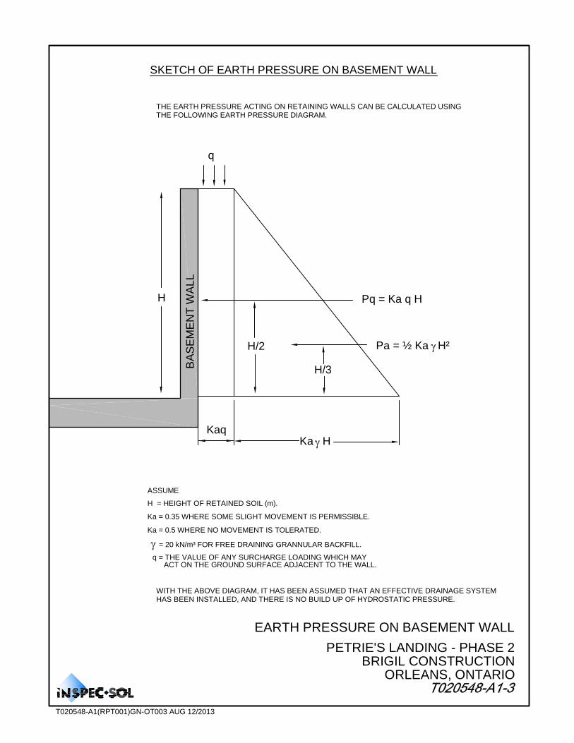
SKETCH OF EARTH PRESSURE ON BASEMENT WALL
THE EARTH PRESSURE ACTING ON RETAINING WALLS CAN BE CALCULATED USING THE FOLLOWING EARTH PRESSURE DIAGRAM.
H
q
H/2
H/3
Pq = Ka q H
Pa = ½ Ka H²
KaqKa H
BA
SE
ME
NT
WA
LL
ASSUME
Ka = 0.35 WHERE SOME SLIGHT MOVEMENT IS PERMISSIBLE.
Ka = 0.5 WHERE NO MOVEMENT IS TOLERATED.
= 20 kN/m³ FOR FREE DRAINING GRANNULAR BACKFILL.
q = THE VALUE OF ANY SURCHARGE LOADING WHICH MAYACT ON THE GROUND SURFACE ADJACENT TO THE WALL.
WITH THE ABOVE DIAGRAM, IT HAS BEEN ASSUMED THAT AN EFFECTIVE DRAINAGE SYSTEMHAS BEEN INSTALLED, AND THERE IS NO BUILD UP OF HYDROSTATIC PRESSURE.
H = HEIGHT OF RETAINED SOIL (m).
EARTH PRESSURE ON BASEMENT WALL
PETRIE'S LANDING - PHASE 2BRIGIL CONSTRUCTION
ORLEANS, ONTARIO
T020548-A1(RPT001)GN-OT003 AUG 12/2013
Enclosures
◆ Enclosures No. 1 - 3
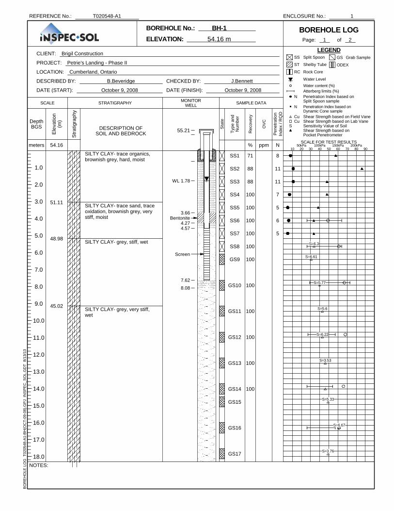
SILTY CLAY- trace organics,brownish grey, hard, moist
SILTY CLAY- trace sand, traceoxidation, brownish grey, verystiff, moist
SILTY CLAY- grey, stiff, wet
SILTY CLAY- grey, very stiff,wet
51.11
48.98
45.02
SS1
SS2
SS3
SS4
SS5
SS6
SS7
SS8
GS9
GS10
GS11
GS12
GS13
GS14
GS15
GS16
GS17
Bentonite
Screen
WL 1.78
3.66
4.274.57
7.62
8.08
71
88
88
100
100
100
100
100
100
100
100
100
100
100
8
11
11
7
5
6
5
55.21Ele
vatio
n(m
)
Str
atig
raph
yCHECKED BY: J.Bennett
DATE (START): October 9, 2008
Page: 1
STRATIGRAPHY
of 2
LEGEND
ENCLOSURE No.: 1
OV
C
DESCRIPTION OFSOIL AND BEDROCK
SCALE SAMPLE DATA
SCALE FOR TEST RESULTS
10 20 30 40 50 60 70 80 90meters
CLIENT: Brigil Construction
BOREHOLE LOG
50kPa 100kPa 150kPa 200kPa
ELEVATION: 54.16 m
PROJECT: Petrie's Landing - Phase II
LOCATION: Cumberland, Ontario
DATE (FINISH): October 9, 2008
ppm
DepthBGS
1.0
2.0
3.0
4.0
5.0
6.0
7.0
8.0
9.0
10.0
11.0
12.0
13.0
14.0
15.0
16.0
17.0
18.0
BOREHOLE No.: BH-1
54.16
NOTES:
REFERENCE No.: T020548-A1
DESCRIBED BY: B.Beveridge
BO
RE
HO
LE L
OG
T02
0548
-A1-
BH
(OC
T-0
9-08
).G
PJ
INS
PE
C_S
OL.
GD
T 8
/13/
13
Sta
te
Typ
e an
dN
umbe
r Cu Shear Strength based on Field Vane
GS Grab Sample
ODEX
Cu Shear Strength based on Lab Vane
Shear Strength based onPocket Penetrometer
N Penetration Index based onDynamic Cone sample
N Penetration Index based onSplit Spoon sample
Atterberg limits (%)
ST Shelby Tube
SS Split Spoon
S Sensitivity Value of Soil
Water content (%) Water Level
RC Rock Core
MONITORWELL
%
Rec
over
y
N
Pen
etra
tion
Inde
x / R
QD
S=6.3
S=6.61
S=5.77
S=5.6
S=6.22
S=3.53
S=5.33
S=6.67
S=3.76
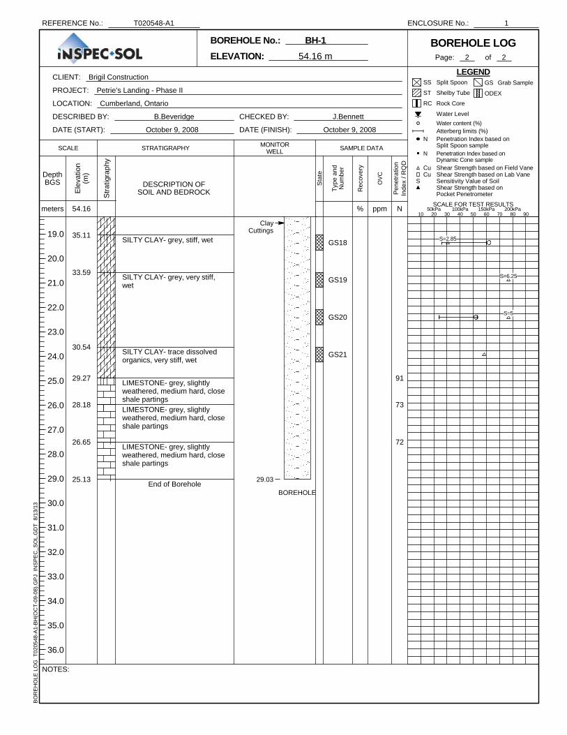
SILTY CLAY- grey, stiff, wet
SILTY CLAY- grey, very stiff,wet
SILTY CLAY- trace dissolvedorganics, very stiff, wet
LIMESTONE- grey, slightlyweathered, medium hard, closeshale partingsLIMESTONE- grey, slightlyweathered, medium hard, closeshale partings
LIMESTONE- grey, slightlyweathered, medium hard, closeshale partings
End of Borehole
35.11
33.59
30.54
29.27
28.18
26.65
25.13
GS18
GS19
GS20
GS21
BOREHOLE
ClayCuttings
29.03
91
73
72
Ele
vatio
n(m
)
Str
atig
raph
yCHECKED BY: J.Bennett
DATE (START): October 9, 2008
Page: 2
STRATIGRAPHY
of 2
LEGEND
ENCLOSURE No.: 1
OV
C
DESCRIPTION OFSOIL AND BEDROCK
SCALE SAMPLE DATA
SCALE FOR TEST RESULTS
10 20 30 40 50 60 70 80 90meters
CLIENT: Brigil Construction
BOREHOLE LOG
50kPa 100kPa 150kPa 200kPa
ELEVATION: 54.16 m
PROJECT: Petrie's Landing - Phase II
LOCATION: Cumberland, Ontario
DATE (FINISH): October 9, 2008
ppm
DepthBGS
19.0
20.0
21.0
22.0
23.0
24.0
25.0
26.0
27.0
28.0
29.0
30.0
31.0
32.0
33.0
34.0
35.0
36.0
BOREHOLE No.: BH-1
54.16
NOTES:
REFERENCE No.: T020548-A1
DESCRIBED BY: B.Beveridge
BO
RE
HO
LE L
OG
T02
0548
-A1-
BH
(OC
T-0
9-08
).G
PJ
INS
PE
C_S
OL.
GD
T 8
/13/
13
Sta
te
Typ
e an
dN
umbe
r Cu Shear Strength based on Field Vane
GS Grab Sample
ODEX
Cu Shear Strength based on Lab Vane
Shear Strength based onPocket Penetrometer
N Penetration Index based onDynamic Cone sample
N Penetration Index based onSplit Spoon sample
Atterberg limits (%)
ST Shelby Tube
SS Split Spoon
S Sensitivity Value of Soil
Water content (%) Water Level
RC Rock Core
MONITORWELL
%
Rec
over
y
N
Pen
etra
tion
Inde
x / R
QD
S=2.85
S=6.25
S=5

SILTY CLAY- trace organics,trace oxidation, greenish grey,hard, moistSILTY CLAY- trace organics,trace oxidation, trace sand,greenish grey, hard, moistSILTY CLAY- trace oxidation,trace sand, greenish grey, verystiff, moistSILTY CLAY- trace silt layers,trace oxidation, trace sand,greenish grey, very stiff, moistSILTY CLAY- trace silt layers,trace organics, trace oxidation,greenish grey, stiff, moistSILTY CLAY- trace organics,grey. stiff, wet
SILTY CLAY- trace organics,trace silt seams, grey, stiff, wetSILTY CLAY- trace organics,grey, stiff, wet
End of Borehole
53.70
52.94
52.17
50.65
49.89
47.60
46.84
42.27
SS1
SS2
SS3
SS4
SS5
SS6
SS7
SS8
SS9
SS10
SS11
SS12
ST-1
SS13
ST-2
SS14
BOREHOLE
ClayCuttings
Bentonite
Silica SandScreen
Silica Sand
WL 0.77
3.964.27
7.627.92
12.19
53
96
92
100
100
100
100
100
100
75
100
100
100
100
11
13
12
8
4
3
55.31Ele
vatio
n(m
)
Str
atig
raph
yCHECKED BY: J.Bennett
DATE (START): October 16, 2008
Page: 1
STRATIGRAPHY
of 1
LEGEND
ENCLOSURE No.: 2
OV
C
DESCRIPTION OFSOIL AND BEDROCK
SCALE SAMPLE DATA
SCALE FOR TEST RESULTS
10 20 30 40 50 60 70 80 90meters
CLIENT: Brigil Construction
BOREHOLE LOG
50kPa 100kPa 150kPa 200kPa
ELEVATION: 54.46 m
PROJECT: Petrie's Landing - Phase II
LOCATION: Cumberland, Ontario
DATE (FINISH): October 16, 2008
ppm
DepthBGS
1.0
2.0
3.0
4.0
5.0
6.0
7.0
8.0
9.0
10.0
11.0
12.0
13.0
14.0
15.0
16.0
17.0
18.0
BOREHOLE No.: BH-2
54.46
NOTES:
REFERENCE No.: T020548-A1
DESCRIBED BY: B.Beveridge
BO
RE
HO
LE L
OG
T02
0548
-A1-
BH
(OC
T-0
9-08
).G
PJ
INS
PE
C_S
OL.
GD
T 8
/13/
13
Sta
te
Typ
e an
dN
umbe
r Cu Shear Strength based on Field Vane
GS Grab Sample
ODEX
Cu Shear Strength based on Lab Vane
Shear Strength based onPocket Penetrometer
N Penetration Index based onDynamic Cone sample
N Penetration Index based onSplit Spoon sample
Atterberg limits (%)
ST Shelby Tube
SS Split Spoon
S Sensitivity Value of Soil
Water content (%) Water Level
RC Rock Core
MONITORWELL
%
Rec
over
y
N
Pen
etra
tion
Inde
x / R
QD
S=5.33
S=6.18
S=8.5
S=3.44
S=7.34
S=6.6
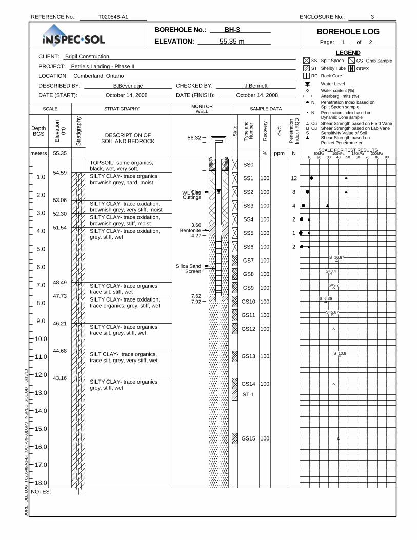
TOPSOIL- some organics,black, wet, very soft,SILTY CLAY- trace organics,brownish grey, hard, moist
SILTY CLAY- trace oxidation,brownish grey, very stiff, moistSILTY CLAY- trace oxidation,brownish grey, stiff, moistSILTY CLAY- trace oxidation,grey, stiff, wet
SILTY CLAY- trace organics,trace silt, stiff, wetSILTY CLAY- trace oxidation,trace organics, grey, stiff, wet
SILTY CLAY- trace organics,trace silt, grey, stiff, wet
SILT CLAY- trace organics,trace silt, grey, very stiff, wet
SILTY CLAY- trace organics,grey, stiff, wet
54.59
53.06
52.30
51.54
48.49
47.73
46.21
44.68
43.16
SS0
SS1
SS2
SS3
SS4
SS5
SS6
GS7
GS8
GS9
GS10
GS11
GS12
GS13
GS14
ST-1
GS15
ClayCuttings
Bentonite
Silica SandScreen
WL 1.89
3.66
4.27
7.627.92
100
100
100
100
100
100
100
100
100
100
100
100
100
100
100
12
8
4
2
1
2
56.32Ele
vatio
n(m
)
Str
atig
raph
yCHECKED BY: J.Bennett
DATE (START): October 14, 2008
Page: 1
STRATIGRAPHY
of 2
LEGEND
ENCLOSURE No.: 3
OV
C
DESCRIPTION OFSOIL AND BEDROCK
SCALE SAMPLE DATA
SCALE FOR TEST RESULTS
10 20 30 40 50 60 70 80 90meters
CLIENT: Brigil Construction
BOREHOLE LOG
50kPa 100kPa 150kPa 200kPa
ELEVATION: 55.35 m
PROJECT: Petrie's Landing - Phase II
LOCATION: Cumberland, Ontario
DATE (FINISH): October 14, 2008
ppm
DepthBGS
1.0
2.0
3.0
4.0
5.0
6.0
7.0
8.0
9.0
10.0
11.0
12.0
13.0
14.0
15.0
16.0
17.0
18.0
BOREHOLE No.: BH-3
55.35
NOTES:
REFERENCE No.: T020548-A1
DESCRIBED BY: B.Beveridge
BO
RE
HO
LE L
OG
T02
0548
-A1-
BH
(OC
T-0
9-08
).G
PJ
INS
PE
C_S
OL.
GD
T 8
/13/
13
Sta
te
Typ
e an
dN
umbe
r Cu Shear Strength based on Field Vane
GS Grab Sample
ODEX
Cu Shear Strength based on Lab Vane
Shear Strength based onPocket Penetrometer
N Penetration Index based onDynamic Cone sample
N Penetration Index based onSplit Spoon sample
Atterberg limits (%)
ST Shelby Tube
SS Split Spoon
S Sensitivity Value of Soil
Water content (%) Water Level
RC Rock Core
MONITORWELL
%
Rec
over
y
N
Pen
etra
tion
Inde
x / R
QD
S=16.67
S=8.4
S=9.2
S=6.36
S=5.87
S=10.8

SILTY CLAY- trace organics,grey, very stiff, wet
SILTY CLAY- trace organics,grey, stiff, wet
LIMESTONE- grey, slightyweathered, medium hard, close,shale partings
LIMESTONE- grey, slightlyweathered, medium hard, closeshale partings
LIMESTONE- grey, slightlyweathered, medium hard, closeshale partings
End of Borehole
37.06
30.97
29.80
28.50
26.98
25.45
GS16
GS17
GS18
RC19
RC20
RC21
BOREHOLE
Silica Sand
29.90
100
100
50
63
95
87
60
73
79
Ele
vatio
n(m
)
Str
atig
raph
yCHECKED BY: J.Bennett
DATE (START): October 14, 2008
Page: 2
STRATIGRAPHY
of 2
LEGEND
ENCLOSURE No.: 3
OV
C
DESCRIPTION OFSOIL AND BEDROCK
SCALE SAMPLE DATA
SCALE FOR TEST RESULTS
10 20 30 40 50 60 70 80 90meters
CLIENT: Brigil Construction
BOREHOLE LOG
50kPa 100kPa 150kPa 200kPa
ELEVATION: 55.35 m
PROJECT: Petrie's Landing - Phase II
LOCATION: Cumberland, Ontario
DATE (FINISH): October 14, 2008
ppm
DepthBGS
19.0
20.0
21.0
22.0
23.0
24.0
25.0
26.0
27.0
28.0
29.0
30.0
31.0
32.0
33.0
34.0
35.0
36.0
BOREHOLE No.: BH-3
55.35
NOTES:
REFERENCE No.: T020548-A1
DESCRIBED BY: B.Beveridge
BO
RE
HO
LE L
OG
T02
0548
-A1-
BH
(OC
T-0
9-08
).G
PJ
INS
PE
C_S
OL.
GD
T 8
/13/
13
Sta
te
Typ
e an
dN
umbe
r Cu Shear Strength based on Field Vane
GS Grab Sample
ODEX
Cu Shear Strength based on Lab Vane
Shear Strength based onPocket Penetrometer
N Penetration Index based onDynamic Cone sample
N Penetration Index based onSplit Spoon sample
Atterberg limits (%)
ST Shelby Tube
SS Split Spoon
S Sensitivity Value of Soil
Water content (%) Water Level
RC Rock Core
MONITORWELL
%
Rec
over
y
N
Pen
etra
tion
Inde
x / R
QD
S=3.52

Appendix A
◆ Notes on Borehole and Test Pits