REPORT ON LIST OF STRUCTURES RECOMMENDED FOR …
60
UNITED STATES DEPARTMENT OF THE INTERIOR GEOLOGICAL SURVEY REPORT ON LIST OF STRUCTURES RECOMMENDED FOR SEISMIC INSTRUMENTATION IN THE PUGET SOUND AREA, WASHINGTON The U.S. Geological Survey Puget Sound Region Instrumentation Advisory Committee (Report compiled by B. Olsen, P. Grant, M. (Jelebi) B. Olsen (Chairman) L. Bush M. Qelebi (Coordinator) J. Clark R. Crosson P. Grant H. Halverson N. Hawkins W. Hancock T. Kinsman R. Maley L. Noson C. Pearson U. Vasishth OPEN-FILE REPORT 89-374 June 1989 This report is preliminary and has not been reviewed for conformity with U. S. Geological Survey editorial standards or with the North American Stratigraphic Code. Any use of trade, firm, or product names is for descriptive purposes only and does not imply endorsement by the U.S. Government.
Transcript of REPORT ON LIST OF STRUCTURES RECOMMENDED FOR …

UNITED STATES DEPARTMENT OF THE INTERIOR
GEOLOGICAL SURVEY
REPORT ON LIST OF STRUCTURES RECOMMENDEDFOR SEISMIC INSTRUMENTATION
IN THE PUGET SOUND AREA, WASHINGTON
The U.S. Geological Survey Puget Sound Region Instrumentation Advisory Committee
(Report compiled by B. Olsen, P. Grant, M. (Jelebi)
B. Olsen (Chairman)L. BushM. Qelebi (Coordinator)J. ClarkR. CrossonP. GrantH. HalversonN. HawkinsW. HancockT. KinsmanR. MaleyL. NosonC. PearsonU. Vasishth
OPEN-FILE REPORT 89-374
June 1989
This report is preliminary and has not been reviewed for conformity with U. S. Geological Survey editorial standards or with the North American Stratigraphic Code. Any use of trade, firm, or product names is for descriptive purposes only and does not imply endorsement by the U.S. Government.

The U.S. Geological Survey Strong-Motion Instrumentation of Structures Advisory Committee for the Puget Sound Region
B. Olsen (Chairman)
L. Bush
M. Qelebi (Coordinator)
J. Clark
R. Crosson
P. Grant
H. Halverson
W. Hancock
N. Hawkins
T. Kinsman
R. Maley
L. Noson
C. Pearson
U. Vasishth
Affiliation
Consulting Engineer, Seattle, WA
Chalker, Putnam, Collins and Scott, Engrs. Inc., Tacoma,
USGS, Menlo Park, CA
Anderson, Bjornstad Kane Jacobs, Inc., Seattle, WA
University of Washington, Seattle, WA
Shannon &: Wilson, Inc., Seattle, WA
Seismic Instrumentation Advisor, Olympia, WA
Seattle District Corps of Engineers, Seattle, WA
University of Washington, Seattle, WA
City of Seattle, Seattle, WA
USGS, Menlo Park, CA
FEMA Regional Office, Seattle, WA
City of Tacoma, Tacoma, WA
State of Washington, Olympia, WA

TABLE OF CONTENTS
Page No.
PREFACE ................................ iv
1.0 INTRODUCTION ........................... 1
1.1 The Need for Instrumentation .................... 1
1.2 Participants in Instrumentation Programs .............. 1
1.3 Objectives of the Instrumentation Program .............. 2
1.4 Objectives of the Advisory Committee ................ 3
1.5 The Scope of the Report ...................... 4
2.0 SITE SELECTION PROCESS ..................... 4
2.1 Purpose .............................. 4
2.2 Research Needs .......................... 5
2.3 Previous Studies .......................... 6
2.4 Seismicity Considerations ...................... 6
2.5 Site Selection Scheme ........................ 8
2.5.1 Objectives .......................... 8
2.5.2 Existing Instrumentation ................... 9
2.5.3 Selection Scheme ....................... 10
2.5.3.1 Location ........................ 10
2.5.3.2 Soil Conditions ..................... 11
2.5.3.3 Soil-Structure Interaction Effects ............. 11
2.5.3.4 Focusing ........................ 14
2.6 Deployment Recommendations .................... 14
2.6.1 Deployment Matrix ...................... 14
2.6.2 Deployment Subgroups .................... 16
2.6.3 Site Selection ......................... 17
2.7 Summary ............................. 20
3.0 THE STRUCTURE SELECTION PROCESS ............... 21
3.1 Introduction ............................ 21
3.2 Structural Parameters ....................... 22
3.3 Site Parameters .......................... 24
ii

4.0 CONCLUSIONS AND RECOMMENDATIONS .............. 24
REFERENCES ............................. 26
TABLES ................................ 29
FIGURES ............................... 51
in
PREFACE
The Pacific northwest, particularly the Puget Sound lowland area, has historically
experienced damaging earthquakes. These occur at a recurrence interval of roughly thirty-
five years, with the most recent in 1965 and the largest preceeding one in 1949, but with
earthquakes causing damage in 1945 and both damage and loss of life in 1946.
While recurrence in this region is not as frequent as in the more seismic regions
of California, the possibility of damage and loss of life is still significant. In spite of this,
little has been done in the region to accomplish the instrumentation of buildings.
In California the USGS instrumentation program has been directed towards special
classes of buildings, since typical buildings are being instrumented by the California State
program. In the Puget Sound region, by contrast, the program will be aimed at a good
pattern of structures of varied framing systems, distributed geographically and with respect
to variations in soil and geological formations, as well as seeking a spatial distribution to
augment understanding of the ground motions and attenuation.
The report which follows represents the efforts of a group of interested individuals.
They have been generous in the donation of their time to this project in the interest of
improving both our understanding of regional seismicity and structural response. This
comprehensive effort could not have been realized without the diligence of Mr. Bruce
Olsen, Chairman of the Committee, and of Mr. Paul Grant, who detailed all soil-related
recommendations.
IV
1.0 INTRODUCTION
1.1 The Need for Instrumentation
Effective earthquake hazard mitigation is dependent on many different factors.
Community and regional recognition of the existing risk, and political acknowledgment
of the importance of hazard mitigation are paramount. Application of effective seismic
codes in building construction, emergency preparedness for response, and public education
concerning the risk are other key factors in hazard mitigation. Technical knowledge both of
ground motion and of the response of structures is critical in making structures earthquake
resistant. Regional variations in seismicity and in geological formations make regional
investigation important.
Seismic codes are aimed primarily at life safety and only secondarily at protection
of property. They are dependent on a thorough understanding of structural behavior
under strong ground motion. Observation of earthquake damage has provided much
initial guidance for conditions to be avoided, and areas to be strengthened. This has
been augmented by laboratory testing; however, information obtained from strong-motion
instruments is still essential to completing the circle.
Much has been learned from seismic experience with instruments located in
California and elsewhere. This has permitted advances in design methods and the
confidence with which the methods can be employed, but there is still inadequate
information concerning nonlinear action, largely due to unavailability of data. It is
therefore desirable to expand the possible sources of new data in order to provide future
information of more value in the preparation of seismic codes. A broader geographic
distribution of instrumentation in areas of known seismicity improves the probability of
obtaining useful information and of increasing the body of data needed to improve seismic
design.
1.2 Participants in Instrumentation Programs
Many Federal agencies participate in the instrumentation of structures, including:
Department of the Army, Corps of Engineers
1
Department of the Navy, Civil Engineer Corps
U.S. Geological Survey
U.S. Bureau of Reclamation
Federal Highway Administration
Veterans Administration
While much of the instrumentation work is coordinated by the U.S. Geological Survey,
overall direction of the National Earthquake Hazard Reduction Program is the responsi
bility of the Federal Emergency Management Administration.
In the state of Washington, bridge instrumentation programs are underway by the
Washington State Department of Transportation (WSDOT), while dams are instrumented
under a program of the Corps of Engineers, and Veterans Administration Hospitals are
instrumented under that agency. Only one city, Tacoma, has developed an instrumentation
program and this was developed in collaboration with USGS. In spite of major rapid growth
in population and in structural density, none of the other large cities in the region have
undertaken such public-safety-conscious action.
1.3 Objectives of the Instrumentation Program
The objective of this instrumentation program is to develop a network of
instrumented structures over a broad seismic region to improve the chances of having
instrumented structures so located as to secure useful information when a strong
earthquake occurs. The total network should incorporate existing or added free-field
stations to augment the information needed by the research and design communities.
Resulting earthquake records obtained from such a network will be of great value to the
interested professions in improving design practice, and furthering the safety of the region
through ultimate improvement of design methods and regulations. This system of well-
instrumented buildings, combined with a suitable array of existing or augmented ground
stations, will serve the research needs of the earth sciences community in establishing a
better understanding of regional strong ground motion.
Information obtained from a well-instrumented structure with a complete set of
recordings augmented by ground stations can provide useful information to:
check the appropriateness of the dynamic model which was used in design
in the elastic range;
determine the importance of non-linear behavior on the overall as well as
the local response of the structure;
follow the spreading non-linear behavior throughout the structure as the
response increases, and frequency and damping vary;
correlate damage or damage patterns with inelastic behavior;
establish ground-motion parameters that correlate well with building
response damage;
provide information which may lead to recommendations to improve
seismic codes; and
assist in identifying source mechanisms, focusing effects or other critical
matters.
1.4 Objectives of the Advisory Committee
In the assignment of members of the committee each received a letter containing
the following paragraph:
"The Advisory Committee will be asked to develop a list of potential structures (buildings, bridges, tanks, lifeline structures, etc.) which are deemed important such that if instrumented, the engineering community can benefit from studying data acquired during strong-motion events. After the list is developed, the next step would be to prioritize these structures for recommendations to the USGS for instrumenting."
In order to provide information of broad usefulness, the building instrumentation should
be augmented by coordination with existing ground stations or relocated ground stations.
This will provide improved seismological information with regard to ground motion of
a broad regional area. To this end the members of the committee with earth sciences
backgrounds have taken a broader view of their assignment.
1.5 The Scope of the Report
In conformance with the initial charge to the committee, the report is basically
limited to providing a list of structures found by the committee to be appropriate for
instrumentation. Priorities have, in turn, been established for these structures. These
priorities are related to the building type and characteristics. They also take into
consideration the geological, geotechnical and seismological aspects of its siting. This will
provide not only useful structural information, but simultaneously and with essentially
no added cost will furnish better regional seismological data. However, additional
recommendations pertaining to ground stations are also included within the report.
2.0 SITE SELECTION PROCESS
2.1 Purpose
A thorough and comprehensive seismic instrumentation program in the Pacific
northwest may provide a wealth of data on the behavior of structures following a strong
earthquake. This data would be of interest to both earth scientists (geotechnical engineers,
geologists, and seismologists) as well as structural engineers. Earth scientists would benefit
from the results of such a program by gaining a better understanding of earthquake source
mechanisms, travel paths, the effects of local geology on site response, and significant
conditions resulting in soil-structure interaction. Similarly, structural engineers would
benefit from a better understanding of the earthquake performance of different types of
structural systems.
Accordingly, the selection of sites for instrumentation must consider the different
needs of earth scientists as well as structural engineers. The following section of the report
addresses the needs of practitioners and researchers in the earth science field, and criteria
will be developed for instrument deployment to meet the needs of those who will utilize
the data acquired. These criteria, when combined with a ranking scheme for addressing
the needs of the structural engineering community (Section 3.0), provides a comprehensive
basis for selecting instrumentation locations.
From an earth sciences perspective, the following factors must be considered in
selecting sites for instrumentation:
research needs within the seismological and engineering communities;
seismic activity and risk to the population at large;
existing accelerographs within the region; and
funding constraints for instrumentation installation and operation.
Based upon these considerations, a scheme was developed for deploying instru
ments at specific sites to provide information on soil-structure interaction and other ef
fects. As an extension of this effort, the existing USGS instrumentation program of ground
stations within Washington state was reviewed and critiqued for station coverage and po
tential station relocations. The results of these studies are subsequently discussed.
2.2 Research Needs
Valuable seismological and engineering data may be obtained through the judicious
selection of sites for strong ground-motion instrumentation. Appropriate deployment of
instruments could provide information on the following:
source mechanism
travel path
focusing (topography/structural discontinuities)
ground-motion characteristics (peak ground-motion values and response
spectra)
variation with magnitude
variation with source distance
variation with soil conditions
soil/structure interaction effects
resonance
boundary conditions
rocking effects
2.3 Previous Studies
Previous studies have been accomplished by others for siting strong ground-motion
accelerograph stations in California (Qelebi et al, 1984; Borcherdt et a/., 1984). In both
of these studies, instrument deployment was based considering the proximity of active
faults and the expected severity of ground shaking at the instrumented site. Instruments
were then deployed adjacent to fault systems having the highest probability of earthquake
activity.
2.4 Seismicity Considerations
The techniques which were applicable for locating strong ground-motion instru
ments in California are not entirely appropriate for Washington state, as the local seismicity
is not typically related to known surface faults. Thus, any instrumentation program for
Washington must consider the unique aspects of the tectonics and seismicity of the region
as a basis for instrument deployment.
While the committee was specifically tasked with providing recommendations for
instrument deployment in the Puget Sound area, it is useful to review the seismicity of
the state of Washington to provide a more complete picture of the tectonics in the Pacific
northwest. Thus, for the purposes of this report, the seismicity and tectonics of eastern
and western Washington will be reviewed as a basis for establishing guidelines for the
instrument deployment scheme.
In many respects, the seismicity of eastern Washington may be similar to that
found in California. Specifically, earthquakes in eastern Washington typically occur at
shallow depths. While some of these events can be associated with known faults which have
established activity or movement rates, most of the events are associated with structural
features such as anticlines. Because these features are not associated with surface faults,
it is not possible to reasonably estimate earthquake recurrence rates based solety upon
geological considerations. While this complicates the assessment of seismicity in eastern
Washington, the issue is somewhat mitigated by the fact that faults in eastern Washington
do not appear capable of producing major earthquakes. Furthermore, the area has a low
population density and inventory of existing significant structures.
The seismicity in western Washington is largely concentrated within the Puget
lowland. The Puget lowland is bounded on the east and west by the Cascade range
and Olympic mountains, respectively, and the lowland extends from Chehalis north into
British Columbia. Earthquakes within the lowland typically tend to occur within two
source zones: a shallow zone corresponding to earthquakes with maximum magnitudes of
5 to 6 or less and a deep zone corresponding to moderate earthquakes with maximum
magnitudes typically greater than 6 to 7, based on historic data. Historical earthquake
activity has not been positively correlated with known or inferred surface faults within the
Puget Sound region. Consequently, the earthquake activity appears to be related to plate
tectonic activity beneath the Puget lowland without regard to surface structures. Thus,
the entire Puget lowland could be assessed as a potential earthquake source zone.
Studies of historical seismicity in the Puget lowland suggest that average recurrence
intervals for a magnitude 6 earthquake range from 10 to 70 years (Rasmussen, Millard and
Smith, 1974). The longer recurrence interval was extrapolated from a one-year study
of microseismicity; whereas, the shorter recurrence interval was based on 133 years of
historical data for events occurring within the Puget lowland. A best estimate of regional
seismicity would probably be within these upper and lower bounds.
Based upon the above range of recurrence intervals, it is estimated that a
magnitude 6 earthquake would have a 2 to 10 per cent annual probability of occurrence.
This estimate is based upon a Poisson distribution for earthquake occurrence which does
not consider the last occurrence of a major earthquake.
In addition to earthquakes occurring beneath the Puget lowland, various researchers
have hypothesized that western Washington could experience a subduction zone earth
quake. This earthquake would likely be centered somewhere near the western coast of
Washington. Research is currently being undertaken to investigate geologic evidence which
may substantiate the occurrence of such a major event prior to written or deduced history
in the region. Although the occurrence of a subduction zone earthquake is speculative at
this stage, various researchers have estimated that a recurrence interval for such an event
would range between several hundred to several thousand years.
As a result of the unique aspects of the seismicity within Washington state, the
following conclusions have been derived for formulating an instrument deployment plan:
1. Based upon historical seismicity and population concentrations, the seismic hazard
in western Washington, specifically the Puget lowland, is significantly greater
than that in eastern Washington. Thus, it is recommended that strong-motion
instruments be located exclusively within western Washington.
2. Earthquake activity in the Puget lowland appears to be unrelated to known or
inferred faults. Therefore, it is recommended that instruments be deployed within
the region based on spatial considerations.
3. There is significant uncertainty in not only the location of a future earthquake
within the Puget lowland but also the recurrence intervals of large events. In this
regard, it is felt that an extremely costly and extensive instrumentation program
would not be economically justifiable. Therefore, to optimize the resources that
may be available, the development of a systematic program for instrumentation
in which accelerographs are installed on a prioritized basis to meet research needs
and funding restrictions is required.
4. Currently, research is being conducted to evaluate evidence of the occurrence
of subduction zone earthquakes in western Washington outside recorded time.
Since the occurrence of such an event is speculative, it is recommended that
instrumentation to record a potential subduction zone earthquake be considered
separately from the building instrumentation program.
2.5 Site Selection Scheme
2.5.1 Objectives
The objective of the site selection process is to develop an integrated instrument
deployment program that, considering the unique aspects of local seismicity and existing
instrumentation, provides a basis for prioritizing instrument deployment to meet research
needs in the seismological and engineering communities. To achieve this goal, it is
first necessary to review the existing accelerograph stations within the state. This data
provides a basis for selecting certain structures for instrumentation. The final step is the
development of a site selection plan which meets current research needs. Elements within
each of these tasks are discussed subsequently.
2.5.2 Existing Instrumentation
A tabulation of existing accelerograph stations within Washington is presented
in Table 1. The locations of these stations are shown in Figure 1. The location of
the instruments shown on Table 1 has been developed from both published (Switzer
et a/., 1981; Hayes and Gori, 1986) and unpublished data. This tabulation includes
accelerograph stations owned by the U.S. Geological Survey as well as other agencies.
Sites of existing instrumentation within the state include buildings, bridges, dams, marine
facilities, downhole arrays, and free-field stations. The coordinates for some of the
U.S. Geological Survey accelerograph stations have been modified from published data to
reflect a more accurate location. Revised station coordinates were obtained from published
literature (Shannon &; Wilson and Agbabian Associates, 19SOa, 19SOb, and 19SOc) or from
scaling locations on topographic maps for stations in Seattle. Information on the geological
conditions at each of the accelerograph stations was determined by reviewing geologic maps
and reports for the various regions. The references which are used in this search are cited
in the bibliography.
As indicated in Figure 1, the majority of accelerograph stations in Washington are
concentrated in the Puget lowland. This deployment of existing instrumentation correlates
well with historical seismic activity within the state which is shown on Figure 2.
The data provided in Table 1 was used to prioritize structural categories for future
instrumentation. Specifically, existing instrumentation within Washington includes:
Structural Category Instrumented Locations
Buildings 32
Bridges (overpass structures) 3
Dams 8Other 4
From the above findings it was concluded that both dams and highway overpasses are
relatively well instrumented considering the number of structures of this nature which exist

within the state. Thus, it is our opinion that the strong-motion instrumentation program
should focus upon instrumenting only buildings.
2.5.3 Selection Scheme
Having inventoried the existing accelerograph stations within the state and concluded
that the instrumentation program should be confined to buildings, it is next necessary to
establish a framework for deploying the instruments to meet the research needs previously
discussed. The following elements, which will be discussed subsequently, provide a
frameworking for instrument deployment:
location
soil condition
potential soil/structure interaction effects
resonance
boundary conditions
foundations
focusing
2.5.3.1 Location
Due to the lack of correlation of seismic activity with known faults within western
Washington, a spatial separation of instruments will be required to provide information
on the source mechanism, travel path, and attenuation of maximum ground motions and
response spectra for the earthquake recording sites. Instruments should be deployed to
accomplish three separate goals. First, a select group of sites should be instrumented in
the Seattle/Bellevue area to provide a multiplicity of information on frequency content and
soil-structure interaction effects. Secondly, sites in outlying areas should be instrumented
to provide adequate coverage for recording local earthquakes within the Puget lowland.
This would necessarily require establishing recording stations in an east-west as well as
north-south array through the Puget lowland. The third goal for the spatial distribution
10

of stations is to provide adequate coverage for the potential occurrence of a subduction
zone earthquake. This would necessarily require locating instruments on the Olympic
Peninsula, which would be close to the source of such an event.
The above goals may be accomplished by both single and multiple instrumentation
at recording sites. Sites with multiple instruments are appropriate for locations in the
Seattle/Bellevue area where studies of special subsurface effects such as soil-structure
interaction will be accomplished. Sites where single instruments will be appropriate
correspond to conditions where only one parameter may be studied, such as ground-motion
characteristics from either a local or subduction zone earthquake.
2.5.3.2 Soil Conditions
To evaluate the influence of soil conditions upon the values of recorded peak ground
motion and response spectra, it is recommended that ground level instruments be deployed
at locations having the following soil types:
alluvium more than 150 feet deep
glacial deposits glacially consolidated silts, clays, and outwash sands and gravels
rock
It is recommended that instruments to study the effects of each of the three soil
types be located relatively close to one another to minimize differences in ground motion
due to different travel paths of the earthquake waves or focusing effects. If possible, it
is recommended to provide instrumentation on all three soil types in both Seattle and
Olympia. This type of information would be useful in developing microzonation guidelines
based upon geologic units.
2.5.3.3 Soil-Structure Interaction Effects
Resonance. It is recommended that instruments be deployed to study potential
effects of soil-structure resonance. A condition of resonance exists when the fundamental
period of the soil deposit underlying a building matches the fundamental period of the
structure. Resonance effects accounted for extensive damage to structures located in
11

Mexico City during the 1985 earthquake. It was typically observed that 15- to 20-
story structures were severely damaged from this earthquake while adjacent 2- to 3-story
structures performed relatively well. Similar earthquake damage patterns have also been
observed in other cities. Additionally, both the Uniform Building Code and the Applied
Technology Council Guidelines for the seismic design of buildings explicitly account for
potential conditions of soil-structure resonance in determining equivalent base shear forces
for the earthquake design of buildings. Thus it would be extremely beneficial to instrument
sites within the Puget Sound area where resonance may occur. Potential study categories
include the following:
low building/stiff soil (glacial deposits)
low building/soft soil (alluvium)
high-rise building/stiff soil
high-rise building/soft soil
It is recommended that buildings selected for this comparison be located within
reasonable proximity to one another, preferably in Seattle, to minimize differences in
ground motion due to different travel paths of the earthquake waves. It may not be
possible to provide complete coverage for this study as high-rise buildings in Seattle are
not typically located on soft soils (alluvium). Therefore, this specific study category may
require instrumentation of a structure outside of the Seattle-Bellevue area.
Boundary Conditions. It is recommended that instruments be deployed to study
various boundary conditions pertinent to the response of the substructure of buildings.
Instrumentation should be deployed to study:
variation of motion below the ground surface
location of input motion in structural models
effects of sloping ground conditions on substructure response
Dynamic analyses of structures within Seattle require an evaluation of each of the
above parameters in formulating the dynamic model of the structure. Instrumentation of
12

appropriate buildings would provide a basis for assessing the assumptions which are made
in the current structural analyses and provide guidance for better modeling procedures.
Instrumenting buildings with deep basements should provide confirmation on the variation
of ground motion with depth below the ground surface as well as related soil-structure
interaction effects. Additionally, locating instruments at both the street level and the
lowest basement level would provide ground motions which may be used in a "back
analysis" of the structure. This back analysis would indicate if the ground motion is
more likely to be transmitted to the building through the floor slabs of the structure at
street level or if the controlling motion to the structure is transmitted through the footings
at the base of the structure. Finally, instrumenting basements of structures where there
is a significant variation in elevation about the site would indicate the appropriate choice
for the location of the ground motion for the structural analyses (i.e., uphill or downhill
side of structure).
It is anticipated that the above information can be conveniently accomplished through
two studies. The first study would instrument buildings with deep basements that are
located on sites having sloping ground conditions and the second study would consist of
instrumenting buildings with deep basements located at sites where the adjacent ground
is level. It is anticipated that the findings from such a study could also be interpolated for
buildings with shallow basements on either level or sloping ground.
Foundations. It is recommended to instrument buildings with different foundation
types to evaluate the potential effect of rocking on the building response. While the
criteria for rocking of structures is based on many factors, it is anticipated that rocking
effects would be amplified for those structures having a fundamental period close to the
natural frequency on the underlying soil. This effect would be most significant for buildings
of intermediate height (5 to 20 stories). While this effect would be less critical for high-rise
structures, it is anticipated that high-rise buildings, instrumented for other purposes, could
also provide useful information on this phenomena which could be extrapolated for use in
the design of intermediate height structures. Therefore, it is recommended that high-rise
buildings with the following foundations be instrumented:
13
piles
drilled piers
mat or footing foundations
Buildings selected for this study do not necessarily need to be constrained to the same
geographic area.
2.5.3.4 Focusing
Previous earthquakes in the Puget Sound area have resulted in concentrated damage
in local areas. One such area is west Seattle which experienced significantly more structural
damage than other areas of the city with similar subsurface soil conditions. It has
been theorized that the bedrock geometry beneath west Seattle caused a focusing of
earthquake waves which resulted in the local concentration of building damage. Therefore,
instrumentation in west Seattle would clarify the issue on the effects of earthquake focusing
on recorded ground motions compared to other areas of the city.
Geological and geophysical studies have indicated that Seattle is cut by a major
structural discontinuity which quite likely is a fault. This structural discontinuity runs
in an east-west direction essentially beneath the center of the city. It has been postulated
that the offset in this structural discontinuity may be as great as 1,000 feet. Thus, as
a result of this major structural feature, it would be beneficial to have seismic recording
instruments located both north and south of this feature to determine if the discontinuity
would have any major effects on recorded ground motions.
In our opinion, both of the above studies address specific geological/seismological
issues. Accordingly, it is our opinion that single accelerograph stations located in west
Seattle and north of the structural discontinuity in Seattle would provide the needed
information for these studies and that multiple instrumentation would not be required.
2.6 Deployment Recommendations
2.6.1 Deployment Matrix
A deployment matrix was developed, as presented in Table 2, which addresses
the issues in the site selection plan. Since a judicious selection of sites for the
14

deployment of instruments may simultaneously satisfy several study areas, a ranking
scheme was developed which would minimize the number of sites which will require
instrumentation. This ranking scheme was arranged to include instrumentation at 10
site/building subgroups, where each subgroup would address a specific study category.
The numerical arrangement of the 10 subgroups in Table 2 indicates the general im
portance of each of the study elements. Therefore, it is recommended that instrumentation
be established on a priority basis in sequence with the site subgroup numbers. This se
quential instrumentation of the sites is desired as many of the study categories require
information from several subgroups to complete a study element. Specifically, information
on resonance effects will require instrumentation from building subgroups 1, 2, 4, and 5.
Thus, it is important to maintain instrument deployment according to this sequencing to
provide the greatest benefit from any recordings of future earthquakes.
The instrument deployment matrix was developed to include sites where both multiple
instruments and single instruments would be required. Multiple instrument arrays,
subgroups 1, 2, 4, 5, and 6, are applicable to sites where it is desired to obtain information
on the effects of soil-structure interaction. Instrumentation is required in only one building
of each of the multiple instrumentation sites (subgroups 1, 2, 4, 5, and 6) to provide
adequate coverage for studying soil-structure interaction and other effects. Sites of single
instruments, subgroups 3, 7, 8, 9, and 10, are appropriate to locations where it is only
desired to obtain information of the earthquake motions at the ground surface. These sites
may be either free-field locations or ground level installations within existing buildings.
Building subgroup 9 was developed to evaluate the spatial variations of earthquake
ground motions as a result of an event occurring locally within the Puget lowland. To
provide adequate coverage for such an event it is recommended that, as a minimum,
accelerograph stations be located in Issaquah, Bremerton, Anacortes, Stanwood, Everett,
Des Moines, Tacoma, Olympia, and Portland. These locations define arrays running
both east-west and north-south within the Puget Sound lowland. Except for Bremerton,
all locations are presently included in the existing USGS accelerograph station network.
Therefore, inclusion of an accelerograph station at Bremerton would be the only
instrumentation required to meet this study objective. This study objective would be best
15

accomplished by the Branch of Engineering Seismology and Geology of the U.S. Geological
Survey.
Building subgroup 10 was specifically developed to record earthquake ground motions
which may occur as a result of a subduction zone earthquake located off the coast
of Washington. In our opinion, instrumentation for this study should have the least
priority as the occurrence of a subduction zone earthquake is speculative. However,
to provide minimal coverage for such an event it is recommended that accelerograph
stations be located at Centralia, Snoqualmie Pass, Port Gamble, Port Townsend, La Push,
Montesano/Satsop, and Trojan (OR). All of these stations, except Snoqualmie Pass, which
is underlain by rock, are located on relatively stable glacial deposits or terrace deposits,
which would provide continuity in subsurface conditions for the recording station sites.
The locations of the proposed new ground stations are indicated on Figure 3. These
ground stations correspond to sites of new instrumentation from subgroups 9 and 10 where
single accelerographs would be required. Again, instrumentation at these sites would be
appropriate for installation by the Branch of Engineering Seismology and Geology of the
U.S. Geological Survey.
2.6.2 Deployment Subgroups
Information on the requirements for the buildings within each of the 10 site building
subgroups is presented in Table 3. The classificational criteria for these subgroups includes
information on the building period, location, basement depth, ground surface adjacent to
the building, and foundation types. The classificational criteria also require information on
the soil conditions at the building sites. To assist in the classification of structures, maps
were developed which indicate the general soil conditions within the Metropolitan Puget
Sound region. These maps generalized the subsurface conditions into alluvium, glacial
deposits, and rock as indicated on Figure 4. Information for this geological classification
was derived from the references which are listed in the bibliography.
Thus, classifying structures within one of the 10 site/building subgroupings requires
information on the building structure and subsurface soil conditions (Figure 4). Candidate
structures for study within each of the subgroups are listed on Table 3. Within
16

each subgroup, the structures have been ranked in descending order of importance for
instrumentation, based upon meeting the objectives of the individual study categories.
Sites or buildings of existing accelerographs are also noted on Table 3.
2.6.3 Site Selection
Five of the site/building subgroups that are listed in Tables 2 and 3 are appropriate for
multiple instrumentation. These correspond to building subgroups 1, 2, 4, 5, and 6. Since
these subgroups correspond to specific soil-structure interaction studies, it is recommended
that all instrumented sites be located within the Seattle/Bellevue area to minimize
variations in recorded ground motion due to differing travel paths of the earthquake waves
or other factors. One building from each of these five subgroupings should be instrumented
prior to deploying instrumentation in outlying areas. Instrumentation of buildings in
outlying areas may be accomplished solely on the basis of structural needs. Section 4.0
of the report presents a master list of buildings recommended for instrumentation, based
upon both geotechnical and structural considerations.
Sites recommended for single accelerograph deployment should be accomplished by the
USGS as funding becomes available. In our opinion, the existing network of USGS-owned
and -operated ground stations within the Puget lowland would provide good coverage
for a local earthquake. However, it is recommended to install a few additional stations
or relocate existing stations to improve the existing network. The following are our
recommendations for new single ground station additions which are independent of any
multiple instrumentation programs which may be accomplished by the USGS.
Seattle Rock Station. Current instrumentation in Seattle includes accelerographs
located both on alluvial deposits and glacial deposits. To complement these sites, it is
recommended to install an accelerograph at a rock site in Seattle. This installation would
correspond to site building subgroup 3 in Table 3. The existing accelerograph at the VA
Hospital in Seattle does not fully meet the criteria for a rock site, as the site subsurface
conditions consist of 20 to 30 feet of glacial deposits overlying bedrock. Consequently, it
is recommended that a free-field rock station be established at a location where the rock
actually outcrops south of the VA Hospital. Such a site may include a free-field instrument
17

shelter at a city park or along the 1-5 freeway cut. Alternatively, it may be possible to
instrument a nearby building located on rock such as the Rehabilitation Center for the
Blind.
Olympia Glacial Station. Similar to Seattle, it is recommended that ground stations
be established in the Olympia/Tumwater area for accelerographs located on alluvium,
glacial deposits, and rock. The existing accelerograph station at the highway test lab
in Olympia is located on alluvial deposits, and the accelerograph station at Tumwater
is located on rock. Thus, to complement these stations, it is recommended that an
accelerograph be located on glacial deposits within the Olympia area. This station could
either be a free field site or a ground station within an existing building such as the Highway
License Building or the Governor's House.
Bremerton Station. To complement the suite of existing ground stations in the Puget
Sound area for recording local earthquakes, it is recommended that a ground station be
established in the Bremerton area. Such a station should be located upon glacial deposits
to correspond to subsurface conditions at similar stations around the Puget Sound. There
are existing accelerograph stations owned by the U.S. Department of the Navy at various
locations within the Puget Sound Naval Shipyard in Bremerton. It is recommended that
one of these sites be included within the USGS accelerograph network. It is recommended
that one of the ground stations along the waterfront be included as any events recorded
at this station could be used to correlate recorded ground motions with damage to any
drydocks or piers during a future earthquake.
Subduction Zone Earthquake Stations. As the lowest priority for station instrumen
tation, it is recommended that the number of ground stations be increased to include sites
for recording ground motions from a subduction zone earthquake. Such an array corre
sponds to site/building subgroup 10 in Table 3. Sites recommended for instrumentation
are located in Centralia, Snoqualmie Pass, Port Gamble, Port Townsend, La Push (Naval
Reserve Station), Montesano/Satsop, and the Trojan power plant in Oregon. It is our un
derstanding that accelerographs already exist at Satsop and the Trojan power plant and
that this would not require new installation but only maintenance of existing instruments.
18
New instruments would therefore be required for installation at five sites. Again, these
sites would have the lowest priority for installation and should be accomplished only after
installation of new instruments at Seattle, Bremerton, and Olympia.
Station Relocations. Based upon our above recommendations and a review of the
existing stations within the USGS network, it is recommended that two stations be
relocated. The first station recommended for relocation is Nisqually. The Nisqually
station is located on alluvial sediments in a relatively undeveloped portion of the Puget
Sound. Thus, any recordings of earthquake motions at this station would be of interest
only regarding the spatial variations of ground motion in the Puget lowland. Due to the
sparse development in the area, recorded motion at this station would not necessarily be
correlated to damage of nearby structures. Considering the above and the fact that the
Nisqually station is relatively close to the existing highway test lab site in Olympia, which
is also located on alluvial soils, it is recommended that the Nisqually station be terminated
or relocated.
The other accelerograph station recommended for relocation is Orting. The Orting
site is one of the few stations in the Puget Sound region located on rock. The information
from this station would be essentially redundant to the existing rock station in Tumwater.
In our opinion, it would be preferable to relocate the Orting station to a glacial site in
Olympia to complement the existing stations on rock and alluvium. Having recording
stations located on all three subsurface conditions in close proximity to one another would
minimize differences in ground motions due to different travel paths of the earthquake
waves between recording stations and thereby provide useful data on the effects of soil
amplification on recorded earthquake ground motions.
It is noted that the rock station in Tumwater is located in a building constructed and
previously used by the University of Washington for recording state-wide seismic events.
The University-owned seismograph has been removed from the facility, leaving only the
USGS accelerographs. The building is not being actively used by the University and the
structure may require maintenance in the near future (new roof). It is recommended that
the USGS establish agreements with the University to maintain the building or establish
19
a separate instrument shelter at the same location.
2.7 Summary
As a result of seismological and engineering considerations, the following recommen
dations are provided for locating earthquake recording equipment within Washington:
1. It is recommended that the instrumentation program be concentrated in the
immediate Puget Sound area as this region has the greatest likelihood of the
occurrence of a moderate or major event and also the highest population and building
concentration within the state.
2. It is recommended that instrumentation be deployed only in buildings, as dams and
highway structures currently have adequate seismic instrumentation.
3. A deployment matrix has been devised as indicated on Table 2 for locating instru
ments within western Washington considering sites of both multiple and single instru
mentation. Sites of multiple instrumentation apply to the building instrumentation
program and address complex factors such as soil-structure interaction. Sites of single
instrumentation are appropriate to the USGS for addressing individual issues such as
frequency content of earthquake ground motion for local and subduction zone earth
quakes.
4. Recommendations for deploying instruments for specific combinations of soil condi
tions and building configurations have been developed and are presented in Table 3.
The individual structures which are shown on Table 3 have been ranked for instru
mentation based solely on geotechnical concerns. Final ranking, including structural
considerations, is discussed in Section 4.0. It is recommended that multiple instru
ments be deployed at five building sites (one in each of the subgroups 1, 2, 4, 5,
and 6) in the Seattle/Bellevue area prior to accomplishing building instrumentaion in
outlying areas.
5. It is recommended that the existing U.S. Geological Survey network of single
instrument ground stations be expanded or modified to improve earthquake coverage
in the Puget Sound area. Specifically, it is recommended that stations be established in
20
both Seattle and Olympia which are located on rock and glacial deposits, respectively.
Secondly, it is recommended that a station be established in Bremerton, possibly
utilizing an existing accelerograph station at the Puget Sound Naval Shipyard, to
complement coverage of existing stations for recording a local event. Finally, it is
recommended that stations be installed at Centralia, Snoqualmie Pass, Port Gamble,
Port Townsend, La Push, Montesano/Satsop, and the Trojan power plant in Oregon to
provide minimal coverage for recording a subduction zone earthquake. These stations
should have the lowest priority for installation. It is recommended that stations
at Nisqually and Orting be relocated as these stations would essentially duplicate
information from sites at Olympia.
3.0 THE STRUCTURE SELECTION PROCESS
3.1 Introduction
Fundamentally, instrumentation of any building or structure provides for the possibil
ity of obtaining useful engineering information in the event of an earthquake. In the Puget
Sound lowland and Pacific northwest region the existing amount of building instrumen
tation is very limited. Thus the potential for obtaining important and useful information
is essentially lacking. To overcome this lack, a plan has been needed whereby adequate
useful information could be secured through a network of instrumentation of regular, typ
ical, average building types. This leaves special conditions and the instrumentation of
irregular buildings to future efforts. From this standpoint the guidelines for selection are
different than those used elsewhere. The aim of this selection process is to obtain a max
imum amount of useful information from the buildings which are chosen. In this report
"useful" is interpreted as valuable in reassessing the particular structure instrumented,
valuable in making comparisons with similar buildings both locally and elsewhere, and
valuable in assisting the understanding of both soil-structure interaction, and potential
source mechanisms.
Initial review of existing conditions discloses a limited number of instrumented
buildings. These are located in Tacoma and have been instrumented under a City-financed
21
program which was developed with the advice of the USGS in the past. There are a number
of ground stations in the region. Some of these are in buildings and some are free field and
may be found listed in Table 1. There is also a program for instrumenting the recently
constructed VA Hospital addition on Beacon Hill in Seattle.
The program for which this report is made is intended to incorporate existing
instrumented structures. In selecting additional buildings, they will be related to the
varied types of construction in the area. Recommendations will at the same time be aimed
at establishing a systematic relation between the structures selected and the soils and
geological conditions encountered and which have been discussed in Section 2.0.
3.2 Structural Parameters
The structural parameters which were considered for establishing a framework for
instrument deployment include building geometry, construction material, age of structure,
past seismic exposure, and availability of original design drawings. These general
categories were used to develop a rating system under which buildings were prioritized for
instrumentation. The rating system used a set of weighting values for each of the structural
categories to differentiate and prioritize building selection. These weighting values were
subjectively selected by the members of the structures subcommitte. The elements of this
structural rating system are shown on Table 4. Only buildings have been recommended for
instrumentation as existing dams and highway bridges have been adequately instrumented
by programs sponsored by the U. S. Army Corps of Engineers and the Washington State
Department of Transportation (WSDOT).
All of these measures have been used elsewhere, but are applied in a somewhat different
manner for this study. Weighting of the factors was directed toward emphasizing regularity
and normal structural conditions, rather than to emphasize unusual types. In this way
the priority is directed toward a maximum of information to be obtained from standard
types of construction.
It is realized that building types selected may be the same as those found in other
areas of high seismicity where instrumentation already exists. In view of the uncertain
nature of earthquake recurrence, it was felt that using structural types common to other
22
seismic areas might give even better assurance of securing early instrumental information
of general interest. This would be of value to the general engineering community and also
to code modification bodies in their efforts to improve the design procedure.
The various parameters which have been utilized have been weighted in an arbitrary
manner to give less value to geometrically irregular structures. In materials, utilizations
which are generally in common use today have been emphasized.
We have not felt great interest in the age of the buildings since many older buildings
have been demolished, and remaining historical buildings have to some extent had seismic
strengthening. On the other hand, we have emphasized buildings in the planning stage,
or currently under construction, in order to permit instrumentation of new buildings of
interest at an appropriate time.
The basic framework established in this manner provided the means for ranking
buildings for instrumentation. Structural engineering members of the committee developed
a list of candidate structures for instrumentation, selecting those which appeared most
representative and of greatest interest. The list was limited to provide geographic
distribution as well as characteristic distribution. These buildings are listed in Table 5. The
geographic distribution of potential buildings for instrumentation also considered existing
instrumentation within the state (Table 1). A master list of buildings recommended for
instrumentation was developed by combining the building rankings from Table 4 with the
list of potential structures (Table 5). This method was used for all of the buildings in the
region, and a listing of global priority over the region was thus established. Since buildings
were located in different towns and cities, an added local priority was also prepared to
apply to individual areas. These priorities, relating to structural parameters only, and not
yet considering soils and geology, are listed in Table 6.
In the list of structures there are also included a number buildings located in the
outlying communities away from the heavily populated and built-up areas. From the
viewpoint of the earth scientists, ground stations in outlying areas serve adequately,
without need of building instrumentation. From the standpoint of the structural engineer,
however, instrumentation of a well-chosen building type away from the primary urban
centers may be of equal value, and some distribution throughout the region may be
23
desirable.
4.0 CONCLUSIONS AND RECOMMENDATIONS
The Advisory Committee on Instrumentation in the Puget Sound area has over
a period of about 16 months given consideration to the need for and significance of
instrumentation of a variety of buildings and other stations throughout the area. The
result has been the various decisions and actions outlined in the foregoing sections and the
recommendations here stated.
A master list of buildings recommended for instrumentation was developed by
combining the building rankings determined in the site-selection process (Section 2.0)
and the structure selection process (Section 3.0). The recommended buildings for
multiple installation are indicated on Table 7 for sites in the Seattle-Bellevue area. It
is recommended that one building from each of the 5 subgroups shown on Table 7 be
instrumented prior to instrumenting buildings in outlying areas to meet the objectives
of the earth sciences subcommittee members in evaluating local geology and soil-
structure interaction effects on site response. Upon successful negotiation with building
owners for permission to instrument the various structures, it is recommended that the
instrumentation committee be contacted for any special requests for locating individual
accelerographs within the structures to address special concerns such as soil-structure
interaction effects.
The usefulness of information obtained from well-instrumented buildings is recognized
from the usefulness of data developed in other regions following earthquakes. The dearth of
adequate building instrumentation in this region is acknowledged, as well as the recurrence
of damaging earthquakes on a relatively frequent basis. The Advisory Committee therefore
urges the early implementation of the instrumentation activities based on the general
priorities determined in this report.
It is recommended that the existing USGS network of single instrument ground
stations be extended or modified to improve earthquake coverage in western Washington.
Specifically, it is recommended that stations be established in both Seattle and Olympia
which are located on rock and glacial deposits, respectively. Candidate structures for
24

these sitings include the Rehabilitation Center for the Blind in Seattle and the Highway
License Building in Olympia. Secondly, it is recommended that a station be established in
Bremerton, possibly utilizing an existing accelerograph station at the Puget Sound Naval
Shipyard, to complement coverage of existing stations for recording a local event. Third,
it is recommended that stations be installed at Centralia, Snoqualmie Pass, Port Gamble,
Port Townsend, La Push, Mont esario-Sat sop, and the Trojan power plant in Oregan to
provide minimal coverage for recording a subduction zone earthquake. These stations
should have the lowest priority for installation. Next, it is recommended that stations at
Nisqually and Orting be relocated as these stations would essentially duplicate information
from sites at Olympia. Finally, it is recommended that the Tumwater rock station site be
relocated to an individual instrument shelter or the USGS negotiate with the University
of Washington to maintain the existing facility.
The Advisory Committee further recommends that a system be established which will
provide for the prompt publication and distribution of instrumental information resulting
from any seismic event of significance.
The Advisory Committee finally recommends that major communities in the area be
urged to assist and augment the development of this program which has been initiated
by USGS. Adoption by major cities of a program similar to that of Tacoma would go far
toward establishment of a truly adequate regional instrumental network.
25
REFERENCES
[1.] Borcherdt, R. D. et a/., 1984, National planning considerations for the acquisition of
strong ground-motion data, Berkeley, Calif., Earthquake Engineering Research
Institute 84 08, 57 pp.
[2.] Celebi, M. (Chairman) et a/., 19S4, Report on recommended list of structures
for seismic instrumentation in the San Francisco bay region, U.S. Geol. Surv.
Open-File Rep. 84-488, 36 pp.
[3.] Deeter, J. D., 1979, Quaternary geology and stratigraphy of Kitsap County.
Washington, M.Sc. thesis, Western Washington Univ., 175 pp.
[4.] Easterbrook, D. J., 1976, Geologic map of western Whatcom County, Washington,
U.S. Geol. Surv. Misc. Inves. Ser. I 854 B, scale 1:62,500, 1 sheet.
[5.] Eddy, P. A., 1966, Preliminary investigation of the geology and ground-water
resources of the lower Chehalis river valley, and adjacent areas, Grays Harbor
County, Washington, Wash. Div. Water Res. Water-Supply Bull. 30, 70 p.
[6.] Garling, M. E., Molenaar, D., Bailey, E. G., VanDenberg, A. S., and Fiedler, G. H.,
1965, Water resources and geology of the Kitsap peninsula and certain adjacent
islands, Wash. Div. Water Res. Water-Supply Bull. 18, 309 p.
[7.] Gayer, M. J., 1976, Geologic map of northeastern Jefferson County, Washington,
Wash. Div. Water Res. Water-Supply Bull 76-21, scale 1:24,000, 1 sheet.
[8.] Hays, W. W. and Gori, P. L., 1986, Proceedings of Conference XXXIII, a workshop
on "Earthquake Hazards in the Puget Sound, Washington area," U.S. Geol.
Surv. Open-File Rep. 86-253, 237 pp.
[9.] Huntting, M. T., Bennett, W. A. G., Livingstone, V. E., and Moen, W. S.,
1961, Geologic map of Washington, Washing. Div. Mines and Geology, scale
1:500,000.
[10.] Liesch, B. A., Price, C. E., and Walters, K. L., 1963, Geology and ground-water
resources of northwestern King County, Washington, Wash. Div. Water Res.
Water-Supply Bull. 20, 241 pp.
26
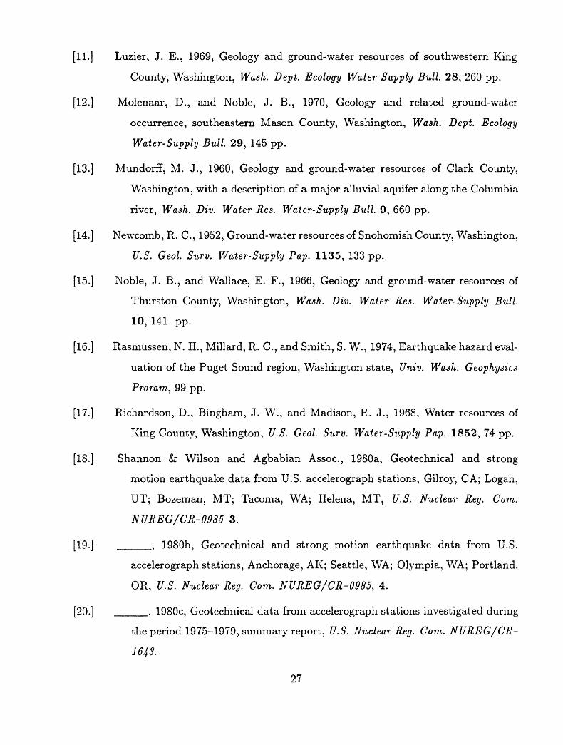
[11.] Luzier, J. E., 1969, Geology and ground-water resources of southwestern King
County, Washington, Wash. Dept. Ecology Water-Supply Bull 28, 260 pp.
[12.] Molenaar, D., and Noble, J. B., 1970, Geology and related ground-water
occurrence, southeastern Mason County, Washington, Wash. Dept. Ecology
Water-Supply Bull 29, 145 pp.
[13.] Mundorff, M. J., 1960, Geology and ground-water resources of Clark County,
Washington, with a description of a major alluvial aquifer along the Columbia
river, Wash. Div. Water Res. Water-Supply Bull 9, 660 pp.
[14.] Newcomb, R. C., 1952, Ground-water resources of Snohomish County, Washington,
U.S. Geol Surv. Water-Supply Pap. 1135, 133 pp.
[15.] Noble, J. B., and Wallace, E. F., 1966, Geology and ground-water resources of
Thurston County, Washington, Wash. Div. Water Res. Water-Supply Bull.
10, 141 pp.
[16.] Rasmussen, N. H., Millard, R. C., and Smith, S. W., 1974, Earthquake hazard eval
uation of the Puget Sound region, Washington state, Univ. Wash. Geophysics
Proram, 99 pp.
[17.] Richardson, D., Bingham, J. W., and Madison, R. J., 1968, Water resources of
King County, Washington, U.S. Geol. Surv. Water-Supply Pap. 1852, 74 pp.
[IS.] Shannon &; Wilson and Agbabian Assoc., 1980a, Geotechnical and strong
motion earthquake data from U.S. accelerograph stations, Gilroy, CA; Logan,
UT; Bozeman, MT; Tacoma, WA; Helena, MT, U.S. Nuclear Reg. Com.
NUREG/CR-0985 3.
[19.] ____, 1980b, Geotechnical and strong motion earthquake data from U.S.
accelerograph stations, Anchorage, AK; Seattle, WA; Olympia, WA; Portland,
OR, U.S. Nuclear Reg. Com. NUREG/CR-0985, 4.
[20.] ____, 1980c, Geotechnical data from accelerograph stations investigated during
the period 1975-1979, summary report, U.S. Nuclear Reg. Com. NUREG/CR-
1643.
27

[21.] Switzer, J., Johnson, D., Maley, R., and Matthieson, R., 1981, Western hemisphere
strong-motion accelerograph station list 1980, U.S. Geol. Surv. Open-File
Rep. 81-664.
[22.] Tabor, R. W. and Cady, W. M., 1978, Geologic map of the Olympic peninsula,
Washington, U.S. Geol. Surv. Misc. Inv. Ser. Map 1 994, scale 1:125,000, 2
sheets.
[23.] Waldron, H. H., Liesch, B. A., Mullineaux, D. R., and Crandell, D. R., 1962,
Preliminary geologic map of Seattle and vicinity, Washington, U.S. Geol. Surv.
Misc. Geol. Inves. Map 1 354, 1 sheet.
[24.] Wallace, E. F., and Molenaar, D., 1961, Geology and ground-water resources of
Thurston County, Washington, Wash. Div. Water Res. Water-Supply Bull. 10.
[25.] Walters, K. L., and Kimmel, G. E., 1968, Ground-water occurrence and stratig
raphy of unconsolidated deposits, central Pierce County, Washington, Wash.
Dept. of Water Res. Water-Supply Bull 22, 428 pp.
[26.] Washington Division of Water Resources Staff, 1960, Water resources of the
Nooksack river basin and certain adjacent streams, Wash. Div. Water Res.
Water-Supply Bull. 12, 187 pp.
[27.] Weigle, J. M., and Foxworthy, B. L., 1962, Geology and ground-water resources of
west-central Lewis County, Washington, Wash. Div. Water Res. Water-Supply
Bull 17, 248 pp.
[28.] Yount, J. C., Dembroff, G. R., and Barats, G. M., 1985, Map showing depth to
bedrock in the Seattle 30' by 60' quadrangle, Washington, U.S. Geol Surv.
Misc. Field Studies Map MF-1692, scale 1:100,000, 1 sheet.
28

TABLE
1
EXIS
TING
ACC
ELER
OGRA
PH S
TATI
ONS
Station
Identification
No.
2178
ANA
2186
BL
O
2185
BM
I
2197
2161
CJD
2122
EVT
2173
SBM
City
Anacortes
Bang
or
Bell
evue
Bell
lngh
am
Blal
ne
Brem
erto
n
Brem
erton
Brem
erto
n
Chie
f Jo
seph
Dam
Everett
Fede
ral
Way
Name
Residence
4 Ro
cky
Road
Dry
Dock _
Trid
ent
Submarine
Base
Fwy.
Overpa
ss
I-90/136th A
ve.
S.E.
Fwy.
Overpa
ss
I-5/Bakerv
lew
Rd.
City
Maintenance Y
ard
Dry
Dock __
Puget
Sound
Naval
Shipyard
Wate
r Pi
t Fa
cili
ty
Puge
t So
und
Naval
Shipyard
Hospital
Puget
Soun
d Naval
Ship
yard
Courthouse
1810 W
all
St.
Bulk
Mall
Fac.
(Bldg. 3)
34301
9th
Ave. So.
Coor
d.
48028'
12"N
12
2°39
'00"
W
47°4
3'N
122°44'W
47°3
4'46
"N
122°
09'0
5"W
48°4
7'42
"N
122°
30'4
0"W
48°5
9'46
"N
122°
44'3
1"W
47°33'N
122°
37'W
47°33'38"N
122°
37'1
4"W
47°33'45"N
122°38'37"W
47°59'42"N
1 19° 38'
00"
W
47°5
8'48
"N
122°
12'3
6"W
47°17'42"N
122°19'27"W
Stru
ctur
e Type/Size
Instr. Shelter
C
5 -
220'
(m
ax.)
sp
an
steel
gird
er
3 -
180'
(m
ax.)
sp
an
cone,
box
gird
er
1-story
bldg.
3-story, R/
C substr
. &
steel
supe
r str.
8- st
ory
tower
3-st
ory
anci
llar
y steel
frame
Cone.
Gravity
Dam
918'
lo
ng;
170'
hi
gh
5-st
ory
bldg.
1-story, steel
fram
e
Inst
rume
nts
No. /Location
1/Gn
d.
2/Gnd. &
Dock
2/Gn
d. &
Bridge
Deck
2/Gnd. &
Brid
ge
Deck
1/Gn
d.
3/Gnd. &
Dock
3/Bs
mt,
1st
& cr
ane
1 3/Crest, L.
gallery, Dn.
Strm
.
1/Bsmt.
1/Gnd.
Owne
r
USGS
USN
USGS
/ WSDOT
USGS
/ WSDOT
USGS
USN
USN
USN
ACOE
USGS
USGS
Geology
Rock
Glacial
Glacial
Glac
ial
Glac
ial
Glacial
Glacial
Glacial
Rock
Glacial
Glacial

No.
2168
GCD
2193
2189
HS
D
2187
IS
I
2184
LGD
2127
MC3
7003
7001
7002
2164
MUD
2195
2101
OLY
Stat
ion
Identification
City
Na
me
Gran
d Co
ulee
Dam
G1g
Harb
or
F1re S
tation
15
Howa
rd H
anso
n Da
m
Issa
quah
Fwy.
Ov
erpass
1-90 &
Sunse
t Way
Lowe
r Granite
Dam
McCh
ord
AFB
Passenger
Term.
Mt.
St.
Hele
ns
Cast
le C
reek
Mt.
St.
Hele
ns
Spir
it Lake
Mt.
St.
Hele
ns
Spir
it Lake
Mud
Mountain D
am
Nlsq
ually
Wildlife R
efug
e Of
f.
Olym
pia
Hwy.
Test La
b 318
Stat
e Av
e.
Coord
.
47°57'36"N
118°
58I48"W
47019'59"N
1220
36'0
7"W
47°1
6'55
"N
12r47'28"W
47031'55"N
122°
01'0
6"W
46°39'58"N
117°
25I52"
W
47008'
15"N
12
2°28
'48
HW
46°16'48"N
1220
18'0
0"W
4601
6'12"N
1220
09'36"W
4601
6'12
"N
122°09'36"W
47°08
I24"
N 121
055'
48"W
47°0
4'59
"N
122°43'01"W
47°02'48"N
1220
53'5
r'W
Stru
ctur
e Ty
pe/S
ize
Cone.
Dam
1-story
bldg.
Roll
ed e
arth d
am w
/ rock face,
500' long;
235' hi
gh
3-160' (max.) span
post t
en.
box
girder
Cone.
Dam
w/saddle
em
bank
ment
, 1,650'
long;
136'
high
1-story
bldg.
Down
hole
(I
nstr
u.
Shel
ter
HeSu
rf.)
Down
hole
(Instru.
Shel
ter
H<*S
urf.
)
Instr. Sh
elte
r H
Rock
fUl
w/earth
core
1,250' lo
ng;
425'
hi
gh
1-story
bldg.
Instr. Sh
elte
r A
Instruments
No. /Location
2/U&
L ga
ller
ies
1/Gn
d.
2/To
e, L.
Ab
ut.
2/Gn
d. &
Brid
ge
Deck
5/Cr
est
(R.L.&
Ctr.
) L. gallery,
Dn.
strm
.
1/Gn
d.
1/DH
1 DH
1/Gnd.
3/Crest, R.
Ab
ut.
& To
e
1/Gnd.
1/Gnd.
Owne
r
WPRS
USGS
ACOE
USGS/
WSDOT
ACOE
USGS
USGS
USGS
USGS
ACOE
USGS
USGS
Geol
ogy
Rock
Glacial
Rock
Glacial
Rock
Glac
ial
Rock
(Volcanic
Debr
is)
Rock
(Volcanic
Debris)
Rock
Rock
Alluvium
Alluvium

Station
Identifica
tion
No.
2179
ORT
2105
RSD
2102
SEF
2106
SP
R
2116
SE
A
2181
SCB
2129
VSE
2113
WS
H
2194
2123
VSK
2192
City
Name
Ortl
ng
Quar
ry
Ross
La
ke D
am
Sats
op
Nuclear
Power
Plant
13
Seattle
Seat
tle
Seattl
e
Seat
tle
Seattle
Seat
tle
Shelto
n
Spok
ane
Stanwo
od
Federal
Office
Bldg.
909
1st
Ave.
P1er
20
Sea-Tac
Airport
Concourse
C
Ship
Can
al Gn
d.
3918 6
th N
.E.
VA H
ospital
Bldg.
100
W. Se
a. Hi
gh S
choo
l 40
75 S
.W.
Stev
ens
F1re S
tati
on
100
Franklin S
t.
VA H
ospital
Bldg
. 3
Coun
ty L
ib.
Coord
.
47°0
4'12
"N
122°
12'3
6"W
48043
I48"
N 12
1°04
'12"
W
47°0
0'N
123°
29'W
47°
122
47°
122
47°
122
47°
122
47°
122
47°
122
47°
123
47°
117
48°
36'15"N
°20'06
MW
34'48"N
°20'42"W
26'
39'
33'
34'
°22
13'
°06
42'
°28
14'
39"N
'06"W
19"
'15
45"
'24
39 «
'59
05"
'29
00"
'48N "W N "W N "W N "W N "W
49"N
Stru
ctur
e Ty
pe/S
ize
Instr. Sh
elte
r C
Cone.
Dam
9-story
steel
frame
& R/
C w/
bsmt
s.
1-story
2- st
ory
2-st
ory
9-story
1-story
1 -st
ory
1-story
1- story
bldg.
bldg.
bldg.
bldg.
bldg.
bldg.
bldg.
bldg.
Instruments
No. /
Location
Owner
1/Gnd.
USGS
2/Rt
. Ab
ut.
& U
SCL
I/
WPPS
S
1/Bsmt.
USGS
1/Gn
d.
USGS
1/Bsmt.
USGS
1/Gn
d.
USGS
3/Bs
mt..
5th
& 8th
VA
1/Bsmt.
USGS
1/Gn
d.
USGS
1/Gn
d.
VA
1/Gnd.
USGS
Geology
Rock
Rock
Glacial
(Wea
. Ro
ck)
Glac
ial
Allu
vium
Glacial
Glac
ial
Rock
(30'
Glac
ial)
Glacial
Glac
ial
Rock
Allu
vium
122°
20'4
6"W

Stat
ion
Identification
No.
2104
TCB
2176
TU
M
2131
VVR
2124
VW
W
2158
WY
O
City
Tacoma
Tacoma
Tacoma
Tacoma
Tacoma
Tacoma
Tacoma
Tacoma
Tolt R
iver D
am
Tumwat
er
Vancou
ver
Walla
Walla
Wynooc
hee
Dam
Name
Coun
ty-C
ity
Bldg.
930
Taco
ma A
ve.
S.
Tacoma D
ome
2727 E. D
St.
Taco
ma F
inan
cial
Ce
nter
1145 B
road
way
Plaz
a
F1re
Stati
on E
. 23
16 E
. ll
th S
t.
F1re S
tati
on N
. 4701 N.
41st
F1re
Station S
. 7247 S
o. Park A
ve.
Tacoma G
eneral Hospital
315
So.
K St.
VA H
ospital
Bldg.
81
Seismic
Vault
4th
& C
St.
VA H
ospital
Bldg.
13
VA H
ospital
Bldg.
1109
Coor
d.
47°15'14"N
122°
26'3
9"W
47°14'13"N
122°
25'3
3"W
47°15'06"N
1220
26'1
7MW
47°16'02"N
122°
24'2
6"W
47°17'11"N
122°29'56"W
47°11'26"N
122°
26'2
5"W
47°15'43"N
122°
27'1
1"W
47°07'48"N
122°
34'1
2"W
47°41'24"N
12r4
1'24
MW
47°00'54"N
122°
54'2
9°W
45°38'24"N
122°
39'3
6"W
46°03'36"N
118°
21'3
6"W
47°23'24"N
123°
36'0
0"W
Stru
ctur
e Ty
pe/S
ize
10-s
tory
steel fram
e bldg.
w/bsmt.
Wood
dome
w/co
nc.
walls
14-story s
teel fram
e
1- story w
ood
fram
e w/
brlc
k
1-story
wood
fra
me
w/br
1ck
1 -st
ory
wood
frame
w/br
1ck
7-st
ory
cone,
frame
4-st
ory
bldg.
200'h1gh,
960'
long
Roll
ed E
arth D
am
1-story
wood
-fra
me b
ldg.
1-story
bldg w
/bsmt.
1-story
bldg.
Cone.
Dam
with e
arth
dam
abut.
Inst
rume
nts
No. /
Loca
tion
1/Bs
mt.
1/Gn
d.
1/Bs
mt.
1/Gnd.
1/Bsmt.
1/Gn
d.
Bsmt
.
1/Gnd.
3/Cr
est,
Ab
ut.,
&
Toe
1/Gn
d.
1/Bsmt.
1/Gn
d.
3/U&
L galleries
On.
Strm
.
Owne
r
uses
TDPW
TDPW
TDPW
TDPW
TDPW
TDPW
VA SWD
uses
VA VA ACOE
Geology
Glacial
Glacial
Glacial
Alluvium
Glacial
Glacial
Glacial
Glac
ial
Rock
Rock
Allu
vium
Alluvium
Rock
1,6
90'
lon
g;
175'
hig
h

Lege
nd
No.
- US
GS S
tation N
umbe
r and
abbr
evia
ted
station
name
(Swltzer
and
othe
rs,
1981).
Name -
Bui
ldin
g/St
ruct
ure
name
and a
ddress o
r cr
oss
stre
ets.
Coordinates
- Latitude (
N) a
nd L
ongi
tude
(W)
sc
aled
fro
m topographic
maps.
Stru
ctur
e -
Brief
description
of b
uilding
type,
numb
er o
f st
orie
s, f
raming m
aterial
Bridge l
ength, span,
construction
Dam
height,
length,
cons
truc
tion
.
Inst
r. - Nu
mber
and l
ocations o
f ac
cele
rogr
aphs
within
the
stru
ctur
e.
Owne
r - AC
OE
- Army C
orps o
f En
gine
ers
SCL
- Se
attl
e Ci
ty L
ight
SWD
- Seattle
Water
Depa
rtme
nt
TDPW
- Tacoma D
epar
tmen
t of P
ubli
c Wo
rks
USGS
-
U.S.
Geological
Survey
USN
- U.S. Department o
f Navy
VA
- Veterans A
dmin
istr
atio
n (owned b
y VA a
nd m
aint
aine
d by U
SGS)
WP
PSS
- Wa
shin
gton
Pub
lic
Powe
r Su
pply
System
WPRS
-
U.S.
Water &
Power R
esea
rch
Service
(Bur
eau
of R
ecla
mati
on)
WSDO
T - Wa
shin
gton
State D
epar
tmen
t of T
rans
port
atio
n
Geology
- Alluvium -
Qua
tern
ary
deposits
Glac
ial
- Gl
acia
lly
cons
olid
ated
Quaternary
deposits
Rock
- Tertiary m
etamorphlc/volcanlc
bedrock
Geology
Inferred f
rom
regi
onal
maps
of s
urface g
eology (
see
list o
f re
fere
nces
).
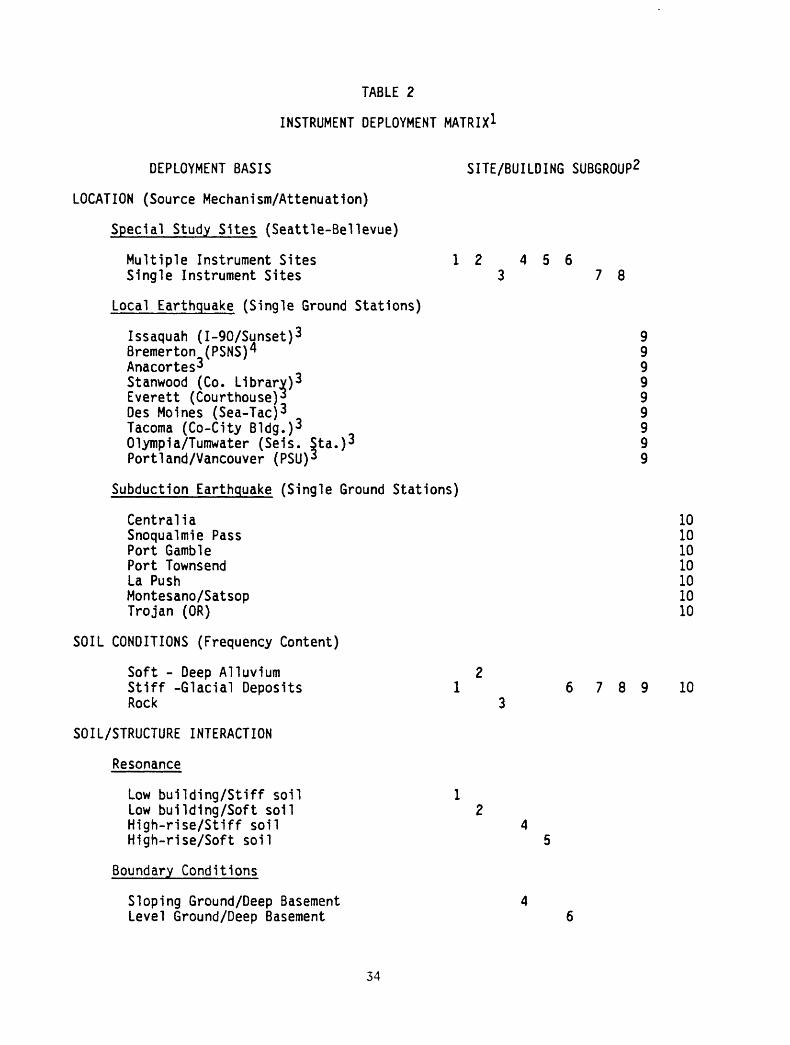
TABLE 2
INSTRUMENT DEPLOYMENT MATRIX1
DEPLOYMENT BASIS SITE/BUILDING SUBGROUP2
LOCATION (Source Mechanism/Attenuation)
Special Study Sites (Seattle-Bellevue)
Multiple Instrument Sites 12 456 Single Instrument Sites 3 78
Local Earthquake (Single Ground Stations)
Issaquah (I-90/Sunset) 3 9Bremerton (PSNS) 4 9Anacortes3 9Stanwood (Co. Library)3 9Everett (Courthouse)3 9Des Moines (Sea-Tac) 3 9Tacoma (Co-City Bldg.) 3 0 9 Olympia/Tumwater (Seis. Sta.) 3 9Portland/Vancouver (PSU) 3 9
Subduction Earthquake (Single Ground Stations)
Centralia 10Snoqualmie Pass 10Port Gamble 10Port Townsend 10La Push 10Montesano/Satsop 10Trojan (OR) 10
SOIL CONDITIONS (Frequency Content)
Soft - Deep Alluvium 2Stiff -Glacial Deposits 1 6 7 8 9 10Rock 3
SOIL/STRUCTURE INTERACTION
Resonance
Low building/Stiff soil 1Low building/Soft soil 2High-rise/Stiff soil 4High-rise/Soft soil 5
Boundary Conditions
Sloping Ground/Deep Basement 4 Level Ground/Deep Basement 6
34
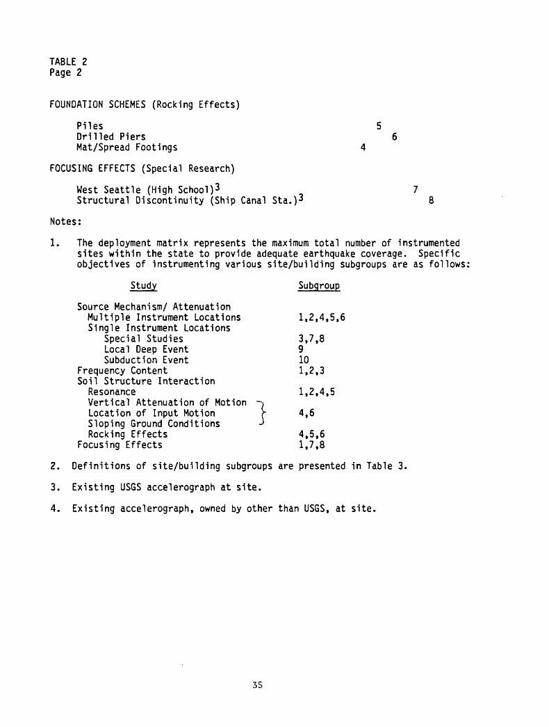
TABLE 2 Page 2
FOUNDATION SCHEMES (Rocking Effects)
Piles 5Drilled Piers 6Mat/Spread Footings 4
FOCUSING EFFECTS (Special Research)
West Seattle (High School) 3 7 Structural Discontinuity (Ship Canal Sta.) 3 8
Notes:
1. The deployment matrix represents the maximum total number of instrumented sites within the state to provide adequate earthquake coverage. Specific objectives of instrumenting various site/building subgroups are as follows;
Study Subgroup
Source Mechanism/ Attenuation Multiple Instrument Locations 1,2,4,5,6 Single Instrument Locations
Special Studies 3,7,8 Local Deep Event 9 Subduction Event 10
Frequency Content 1,2,3 Soil Structure Interaction
Resonance 1,2,4,5 Vertical Attenuation of Motion -^ Location of Input Motion r 4,6 Sloping Ground Conditions J Rocking Effects 4,5,6
Focusing Effects 1,7,8
2. Definitions of site/building subgroups are presented in Table 3.
3. Existing USGS accelerograph at site.
4. Existing accelerograph, owned by other than USGS, at site.
35

TABL
E 3
SITE/BUILDING
SUBGROUPS
1
Subg
roup
1
Subg
roup
2Su
bgro
up 3
Subg
roup
4Su
bgro
up 5
Clas
sifi
cati
on C
riteria:
Building Pe
riod
Location
Soil
Conditions
Basement
Ground Su
rfac
eFoundations
Instruments
Candidate
Stru
ctur
es:
Clas
sifi
cati
on C
riteria:
Building P
erio
d Lo
cati
on
Soil
Co
ndit
ions
: Ba
seme
nt
Ground S
urfa
ce
Foun
dati
ons
Instruments
Candidate
Structures:
0.3-
1.0
sec.
Seat
tle
(dow
ntow
n)Gl
acia
l De
posi
ts
N/A
Mult
iple
Airb
orne
Bld
g.De
nny
Bldg.
Newp
ort
Lane
Fede
ral
Offi
ce B
ldg.
2Re
d Lion
Arli
ngto
n No
rth/
Sout
h
Subg
roup
6
>1.5
sec
Seattle
- Be
llev
ueGlacial
Depo
sits
Deep
Level
Drilled
Piers
Multiple
Two Un
ion
Square
0.3-1.0
sec.
Seattle
Alluvium
N/A
Mult
iple
Sears
Rain
ier
Cold
Sto
rage
Boei
ng C
ngr. Bldg.
King Street St
atio
nCO
E Bl
dg.
Klst
ler
Mors
eEl
deck
Merc
er C
anal
Bl
dg.
Boei
ng F
ield
Pow
er P
lant
Subg
roup
7
0.3-
1.0
sec.
West
Seattle
Glacial
Deposits
N/A
Sing
le
West
Sea
ttle
Hig
h Sc
hool
2
0.3-
1.0
sec.
Seat
tle
Rock
N/A
Sing
le
Rehab. Ct
r. fo
r Blind
V.A. Ho
sp.3
(30' to
Rock)
Subg
roup
8
0.3-
1.0
sec.
North
Seattle
Glacial
Depo
sits
N/A
Single
Ship
Can
al Ground S
ta.2
>1.5 s
ec.
Seat
tle
Glac
ial
Depo
sits
Deep
Slop
ing
Mat/
Foot
ings
Multiple
Colu
mbia
Seaflrst
Cent
erRa
inie
r Tower
Gate
way
Towe
rBl
ock
5Fi
rst
Interstate C
ente
rSe
aflr
st F
ifth A
venu
e Plaza
Seat
tle
Trus
t Tower
Bay
Vist
a To
wer
Wate
rmar
k To
wer
Westln B
ldg.
Hoge
Bld
g.64
Union
Subg
roup
9
N/A
See
below
Glac
ial
Depo
sits
N/A
Sing
le
Issaquah -
I-90/Overoass2
1.5-
2.5
sec.
Seat
tle
- Bellevue
Alluvium
N/A
N/A
Pile
sMu
ltip
le
Worl
d Tr
ade
Cent
er(Tacoma)
Capi
tol
Ctr.
Bl
dg.
(Oly
mpla
)
t
Subg
roup
10
N/A
See
belo
wGlacial
Deposits
N/A
Sing
le
Cent
ral la
West
lake
Pr
ojec
t Crowne P
laza H
otel
4th
I Bl
anch
ard
Bldg
Bell
evue
Pla
ce
One-
Bell
evue
Cen
ter
Rain
ier
Bank P
lace
H.H. Ja
ckso
n Bl
dg.
Vanc
e Bldg.
Bremerton
- Ho
spit
al;*
Des
Moln
es -
Airport*
Taco
ma -
Co.-County B
ldg.
2 Tu
mwat
er -
Sels.
Sta.
2 Po
rtla
nd -
PS
U Cr
amer
Hal
l2
Port G
amble
Port T
owns
end
LaPu
sh (N
aval
Res. St
a.)
Montesano/Satsop
3Tr
ojan
Pow
er P
lant
^
Notes:
1.
Buil
ding
s wi
thin
each subgroup ha
ve be
en ranked in descending or
der
of importance in satisfying th
e cl
assi
fica
tion
al criteria.
2.
Cont
ains
(g
roun
d level
only)
LEGS Accelerograph.
3.
Cont
ains
Accelerograph
owne
d by USGS and
VA (Veterans Administration).
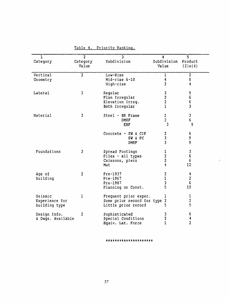
Table 4. Priority Ranking.
1 2 Category Category
Value
Vertical 2Geometry
Lateral 3
Material 3
Foundations 3
Age of 2Building
Seismic 1Experience forbuilding type
Design Info. 2& Dwgs . Available
3Subdivision
Low-RiseMid-rise 6-10High-rise
RegularPlan IrregularElevation Irreg.Both Irregular
Steel - BR FrameDMRFEBF
Concrete - SW & CIPSW & PCDMRF
Spread FootingsPiles - all typesCaissons, piersMat
Pre-1937Pre-1967Pre-1987Planning or Const.
Frequent prior exper.Some prior record forLittle prior record
SophisticatedSpecial ConditionsEquiv. Lat. Force
4Subdivision
Value
142
3221
123
233
1224
2135
1type 2
5
321
5 Product (2)x(4J
284
9663
369
699
366
12
426
10
125
642
*********************
37

Table 5. Structure and Characteristics,
Ir
01
02
03
04
05
06
07
08
03
10
11
12
13
14
15
Kaie Address
Arlington U-S. 1023 First Ave.
?atenark Tower 1011 First Ave.
84 Union Bldg. 84 Union Street
Bayvista Tower 2815 Second Ave.
Seafst 5th Ave Plaza 800 Fifth Ave.
4th i Blanchard Bldg 2101 Fourth Avenue
Vestlake Project 400 Pine Street
Two Union Square 60C University St.
King Street Station 303 So. Jackson
Crowne Plaza Hotel 1113 Sixth Avenue
Seattle Trust Tower 1000 Second Ave.
Boeing Engrg Bldg. 7755 E. Xarginay Hay
Denny Building 2200 Sixth Avenue
Newport Lane 3S50 131st SE
Block Five
(K.Lat.) V. Long.
(47.3619) 122.2007
(47.3621) 122.2009
(47.3630) 122.2019
(47.302) 122.2101
(47.3621) 122.1944
(47.3652) 122.2025
(47.3643) 122.2010
(47.3637) 122.1953
(47.3600) 122.1946
(47.3629) 122.1951
(47.3622) 122.2000
(47.3202) 122.1846
(47.3703)
(47.3445) 122.1020
(47.3627)
Built (Reiod)
1901 (1982)
1983
1985
1982
1980
1978
1987
1987-8
1904
1980
1986
1940 (1987)
1968
1987
1987-8
Mr.Stories
7
23
15
20
42
27
25
58
3*Tow.
33
44
5
11
7
55
Structural Systei
Conc.SSt URH
Dual,RCS?t RCMRF
Dual, RCS«+ RCXRF
RCMRF
SBRFl 25«xt MF
Dual 1 vy SMRF 1 wy
SMRF 1 wy EBF 1 wy
SBF Int 25* Ext FR
URM, Steel
RCDMRF
SMRF Con. Enc. Cols
SC S?1 added
SHRF
RCMRF
SMRF+
K
1.33
0.80
1.00
0.67
0.80
0.80 1.00
0.67 1.00
1.00
0.67
0.67
1.00
0.67
0.67
T Foundations Topog. Sec. Type Depth
0.35 Piles Shallow Slope
2.3 Piers Shallow Slope
0.75 Piers Shallow Slope
2.00 Spread Shallow Level.
4.20 Piers Deep Slope
Level
2.50 Level
2.90 Piers Deep Level
0.30 Shallow Level
3.30 Mat Shallow Level
4.40 Piers Shallow Slope
0.50 Piles Shallow Level
0.55 Spread Shallow Level
0.70
5.50 Slope1201 Third Ave. 122.2006
33
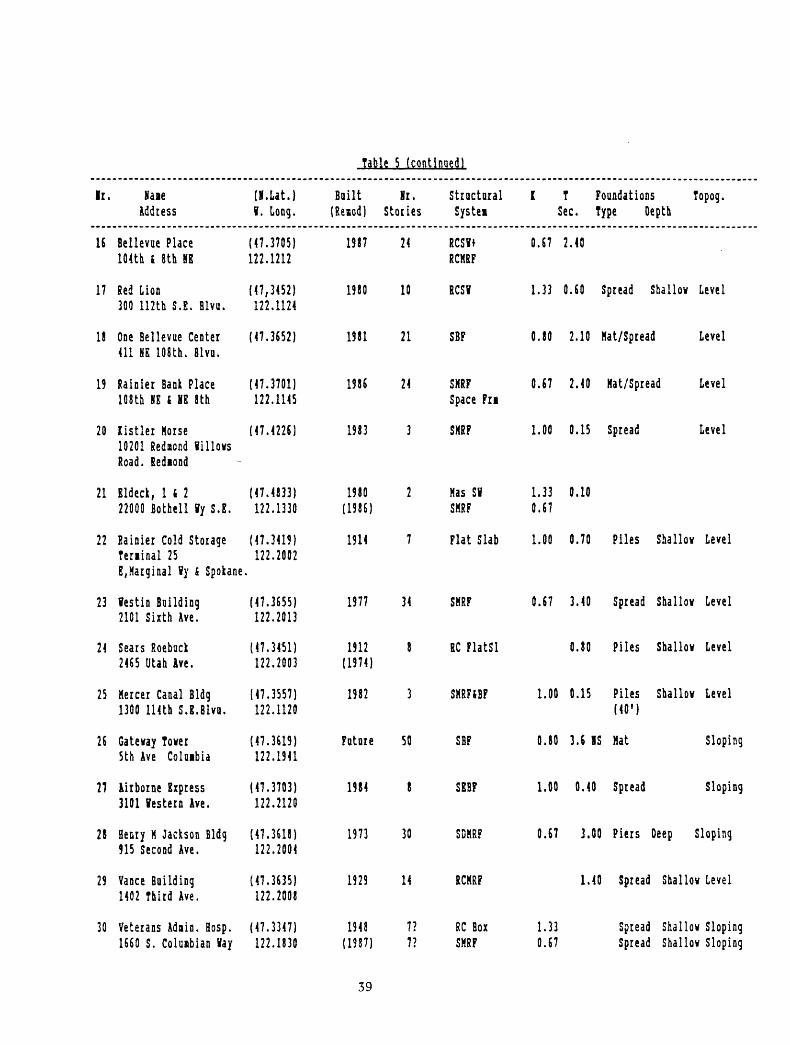
Table 5 (continued)
Ir.
16
17
18
19
20
21
22
23
24
25
26
27
28
29
30
Haie Address
Bellevae Place 104th i 8th HE
Red Lion 300 112th S.E. Blva.
One Bellevae Center 411 HE 108th. Blvu.
Rainier Bank Place 108th HE i HE 8th
Kistler Morse 10201 Redaond lillows Road. Redaond
Eldeck, 1 i 2 22000 Bothell fy S.E.
Rainier Cold Storage Terainal 25 E, Marginal ly & Spokane
festin Building 2101 Sixth Ave.
Sears Roeback 2465 Utah Ave.
Mercer Canal Bldg 1300 114th S.E.Blvn.
Gateway Tower 5th Ave Coloibia
Airborne Express 3101 Western Ave.
Henry M Jackson Bldg 915 Second Ave.
Vance Building 1402 Third Ave.
Veterans Adain. Hosp. 1660 S. Colusbian Hay
(K.Lat.) V. Long.
(47.3705) 122.1212
(47,3452)122.1124
(47.3652)
(47.3701) 122.1145
(47.4226)
(47.4833) 122.1330
(47.3419) 122.2002
(47.3655) 122.2013
(47.3451) 122.2003
(47.3557) 122.1120
(47.3619) 122.1941
(47.3703) 122.2120
(47.3618) 122.2004
(47.3635) 122.2008
(47.3347) 122.1830
Built 8r. (Reaod) Stories
1987
1980
1981
1986
1983
1980 (1986)
1914
1977
1912 (1974)
1382
Future
1984
1973
1929
1948 (1987)
24
10
21
24
3
2
7
34
8
3
50
8
30
14
7? 7?
Structural Systei
RCSI* RCMRF
RCS9
SBF
SMRF Space Fri
SMRF
Mas SH SMRF
Flat Slab
SMRF
RC FlatSl
SMRFiBF
SBF
SEBF
SDMRF
RCMRF
RC Box SMRF
1 T Foundations Topog. Sec. Type Depth
0.67
1.33
0.80
0.67
1.00
1.33 0.67
1.00
0.67
1.00
0.80
1.00
0.67
1.33 0.67
2.40
0.60 Spread Shallow Level
2.10 Mat/Spread Level
2.40 Mat/Spread Level
0.15 Spread
0.10
0.70 Piles
3.40 Spread
0.80 Piles
0.15 Piles (40')
3.6 KS Mat
0.40 Spread
3.00 Piers
1.40 Spread
Spread Spread
Level
Shallow Level
Shallow Level
Shallow Level
Shallow Level
Sloping
Sloping
Deep Sloping
Shallow Level
Shallow Sloping Shallow Sloping
39
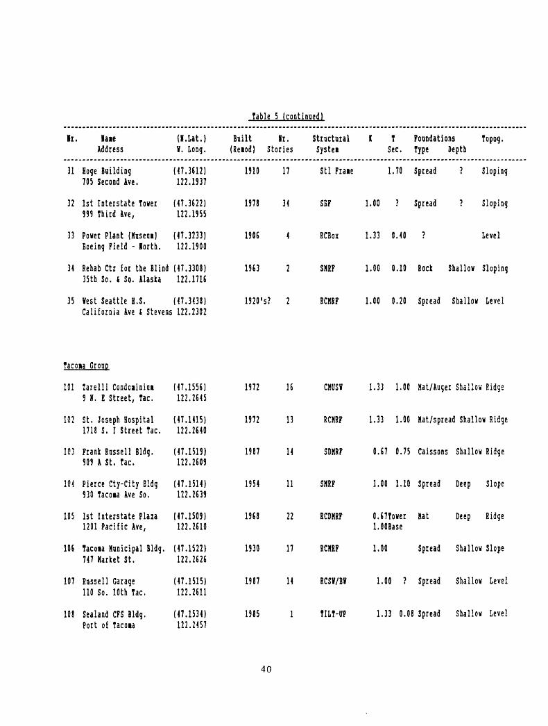
Table 5 (continued)
ll.
31
32
33
laieAddress
Hoge Building 705 Second Ave.
1st Interstate Tover 999 Third Ave,
Power Plant (Mnseni) Boeing Field - lorth.
(H.Lat.) V. Long.
(47.3612) 122.1937
(47.3622) 122.1955
(47.3233) 122.1900
Built Hr. Structural K T Foundations Topog. (Reiod) Stories Systei Sec. Type Depth
1910 17 Stl Fraie 1.70 Spread ? Sloping
1978 34 SBF 1.00 ? Spread ? Sloping
1906 4 RCBox 1.33 0.40 ? Level
34 Rehab Ctr for the Blind (47.3308) 35th So. i So. Alaska 122.1716
35 Vest Seattle H.S. (47.3438) California Ave i Stevens 122.2302
1563 2 SMRF 1.00 0.10 Rock Shallow Sloping
1920's? 2 RCHRF 1.00 0.20 Spread Shallov Level
Tacoia Group
101 larelli Coadoainim (47.1556)9 N. E Street, Tac. 122.2645
102 St. Joseph Hospital (47.1415)1718 S. I Street Tac. 122.2640
103 Frank Russell Bldg. (47.1519)909 A St. Tac. 122.2609
104 Pierce Cty-City Bldg (47.1514)930 Tacota Ave So. 122.2639
105 1st Interstate Plaza (47.1509)1201 Pacific Ave, 122.2610
106 Tacoia Municipal Bldg. (47.1522)747 Market St. 122.2626
107 Rnssell Garage (47.1515)110 So. 10th Tac. 122.2611
108 Sealand CFS Bldg. (47.1534)Port of Tacoia 122.2457
1972 16 CMS? 1.33 1.00 Mat/Auger Shallow Ridge
1972 13 RCMRF 1.33 1.00 Mat/spread Shallow Ridge
1987 14 SDMRF 0.67 0.75 Caissons Shallov Ridge
1954 11 SMRF 1.00 1.10 Spread Deep Slope
1968 22 RCDMRF 0.67Tover Mat Deep Ridgel.OOBase
1930 17 RCMRF 1.00 Spread Shallov Slope
1987 14 RCSI/BI 1.00 ? Spread Shallov Level
1985 1 TILT-UP 1.33 0.08 Spread Shallov Level
40
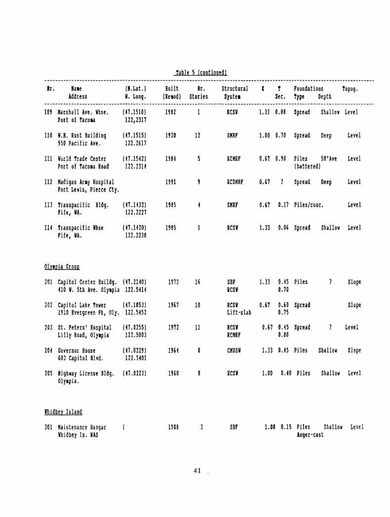
Table 5 (continued!
Mr,
109
110
111
112
113
IK
Naie Address
Marshall Ave. Vhse. Port of Tacoia
I.E. Rust Building 950 Pacific Ave.
¥orld Trade Center Port of Tacoaa Road
Kadigan Any Hospital Fort Levis, Pierce Cty.
Transpacific Bldg. Fife, »A.
Transpacific Ihse Fife, IA,
(H.Lat.) Built Hr. I. Long. (Reiod) Stories
(47.1510) 1982 1 122,2317
(47.1515) 1920 12 122.2617
(47.1542) 1984 5 122.2314
1991 9
(47.1432) 1985 4 122.2227
(47.1420) 1985 1 122.2230
Structural Systei
RCS?
SKRF
RCMRF
RCDHRF
SKRF
RCSV
1 TSec.
1.33 0.08
1.00 0.70
0.67 0.90
0.67 ?
0.67 0.17
1.33 0.06
Foundations Type Depth
Spread Shallov
Spread Deep
Piles 58'Ave (battered)
Spread Deep
Piles/cone.
Spread Shallov
Topog.
Level
Level
Level
Level
Level
Level
OlvBDJa Group
201
202
203
204
205
Capitol Center Buildg. 410 I. 5th Ave. Olyipia
Capitol Lake Tover 1910 Evergreen Pk, Oly,
St. Peters' Hospital Lilly Road, Olyipia
Governor House 602 Capitol Blvd.
Highway License Bldg.
(47.2140) 1972 16 122.5414
(47.1053) 1967 10 122.5452
(47.0255) 1972 11 122.5003
(47.0229) 1964 8 122.5401
(47.0223) 1960 8
SBF RCSI
RCSV Lift-slab
RCSI RCKRF
CKUSV
RCS?
1.33 0.45 0.70
0.67 0.60 0.75
0.67 0.45 0.80
1.33 0.45
1.00 0.40
Piles ?
Spread
Spread ?
Piles Shallov
Piles Shallov
Slope
Slope
Level
Slope
LevelOlyipia.
fhidbey Island
301 Maintenance Hangar Vhidbey Is. HAS
1988 SBF 1.00 0.15 Piles Shallov Level lager-cast
41
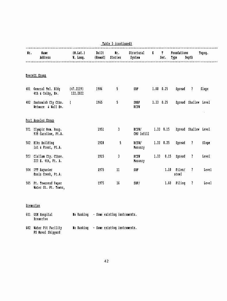
Table 5 (continued)
Vr. Vaie (H.Lat.) Address V. Long.
Built Mr. (Reiod) Stories
Structural Systei
1 T Foundations Topog. Sec. Type Depth
Everett Group
401
402
Pert
501
502
553
504
505
General Tel. Bldg (47.2119) 4th i Colby, Ev. 122.2022
Snohoiish Cty Cths. ( VetBore i Vail Ev.
Angeles Group
Olyfipic Met. Rosp. 939 Caroline, Pt.A.
Elks Building 1st i Front, Pt.A.
Clallai Cty. Cthse. 223 E. 4th, Pt. A.
ITT Rayonier Ennis Creek, Pt.A.
Pt. Townsend Paper
1986 5
1965 5
1951 3
1928 5
1915 3
1975 11
1975 16
SBF
SMRF RCSV
RCS?/ CMU Infill
RCS?/Masonry
RCS? Masonry
SBF
SBP/
1.00 0.25 Spread
1.33 0.25 Spread
1.33 0.15 Spread
1.33 0.25 Spread
1.33 0.15 Spread
1.10 Piles/ steel
1.60 Piling
? Slope
Shallow Level
Shallow Level
? Slope
? Level
? Level
? Levellater St. Pt. Towns,
Breierton
601 USK Hospital Breaerton
602 later Pit Facility PS Vaval Shipyard
lo Ranking - Soie existing instruments,
Ko Ranking - Soie existing instruments,
42

Table 5 (continued!
If i. XaieAddress
(I.Lat.) V. Long.
Built Ir. (Reiod) Stories
Structural X T Foundations Topog. Systei Sec. Type Depth
Bsllinqhat Group
701 Vhatcoi Cty Cthse Bellingha*
702 Lincoln Square 409 York
703 Leopold Hotel Cornvall
704 fiend HallWestern Va Univ
5
1970 10
1920's 11
WO's 4
RCHRP/ 1.33 0.5 ? RCSV
Level
RCBoi/ 1.33 Piles Shallow BluffBrgVall edge.
SFRH/ 0.50 Spread Shallov LevelMas. Infill 0.75 (rock)
RCBox/ 1.00 0.17 Piles ? ?Mas.Infill 0.28 (peat)
HRP = Koient Resisting PraieDMRP = Ductile Koient-resisting FraieRC = Reinforced ConcreteS - SteelBP = Braced PraceRCSV - Reinforced Cone. Shear VailsBV - Bearing Vail
Unlisted structures of earth sciences interest:
Federal Office Building 909 1st Ave. Seattle. COB Building - 4725 E. Marginal Vay, Seattle. Cohibia Seafirst Center, Seattle. Rainier Tover.
43

Table 6. Strnctoral Group Priority Evaluation and Ranking
Xr
01
02
03
04
05
05
07
08
09
10
11
12
13
14
15
Name Geoietry Hat Address Vert Lat
Arlington H-S 81023 First Ave.
lateraark Tover 41011 First Ave.
84 Union Building 484 Union St.
Bay Vista Tower 42815 Second Ave.
Seafst 5th Ave. Plaza 4800 Fifth Ave.
4th i Blanchard Bldg 42101 Fourth Ave.
Yestlake Project 4400 Pine St.
Tvo Union Square 4600 University Street
King Street Station 2303 So. Jackson St.
Crovne Plaza Hotel 41113 Sirth Ave.
Seattle Trust Tower 41000 Second Avenue
Boeing Engrg Bldg 27755 E. Marginal By S.
Denny Building 82200 Sixth Ave.
Hevport Lane 83650 131st S.E.
Block 5 4
9 6
6 6
9 6
6 9
9 3
6 3
6 9
9 9
6 6
9 9
3 6
6 6
9 3
9 9
9 6
Fdn
6
6
3
3
6
3
3
6
6
12
3
6
3
3
3
Age
4
6
6
6
6
6
10
10
4
6
6
2
6
6
10
Seis Des Exp Dwgs
5
1
1
1
1
1
5
5
1
1
1
1
1
1
1
4
2
2
2
6
2
2
6
2
2
2
2
2
2
6
SUM Cou. Subject.
42 -13
31
31
31
35
25
39
49
27 -13
43 t!3
25
25
32
38
39 413
Geology Revised A,G,R SUB
A
A
G
G
G
G
G
G
A
G
G
A
G
G
G
29
31
31
31
35
25
39
49
14
56
25
25
32
38
52
Priority Global Local
44
40
40
40
23
49
17
10
60
1
53
53
32
18
7
23S
20S
21S
22S
15S
32S
us
7S
33S
IS
29S
30S
20S
12S
4S1201 Third Ave.
44
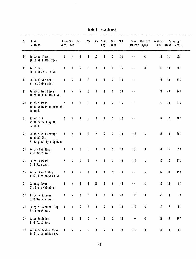
Table 6. (continued)
Hr
16
17
18
19
20
21
22
23
24
25
26
27
28
29
30
Baie Geometry Mat fdn Age Seis Des SUM COM. Geology Address Vert Lat Exp Dvgs Subjctv A,G,R
Bellevue Place 4 9 9 3 10 1 2 38 -- GlOUh NE S 8th. Blvd.
Red Lion 8 9 6 3 S 1 2 35 -- G300 112th S.E. Blvu.
One Bellevue Ctr. 4 6 3 3 6 1 2 25411 HE 108th Blvu
Rainier Bank Place 4 £ 6 3 6 1 2 28108th KE t Kg 8th Blva.
listler Morse 2 9 3 3 6 1 2 2610201 Rednond-Villovs Rd.Redaond.
Eldeck 1,2 2 9 9 3 6 1 2 3222000 Bothell ?y SEBothell
Rainier Cold Storage 8 9 9 6 4 2 2 40 413 ATeminal 25.E. Marginal Vy s Spokane
Sestin Building 4 9 3 3 6 1 2 28 +13 G2101 Sixth Ave.
Sears, Roebuck 2 6 6 6 4 1 2 27 U3 A2465 Utah Ave.
Hercer Canal Bldg. 2 9 6 6 6 1 2 32 -- A1300 114th Ave.SE Blvu
Gateway Tower 4 9 6 6 10 1 6 42 -- G5th Ave.i Co 1mb ia
Airborne Express 8 6 9 3 6 2 ( 40 +13 G3101 Western Ave.
Henry M. Jackson Bldg 4 9 6 6 6 2 6 39 H3 6915 Second Ave.
Vance Building 4 6 6 3 4 1 2 26 -61402 Third Ave.
Veterans Adain. Bosp. 8 6 6 3 6 2 6 37 *13 G
Revised Priority SUB. Global Local.
3! 18 13S
35 23 16S
25 53 31S
28 47 24S
26 48 27S
32 32 18S
53 4 20S
41 15 SS
40 16 17S
32 32 19S
42 14 8S
53 4 3S
52 7 5S
26 48 26S
50 9 6S1660 S. Coluabian Vy.
45
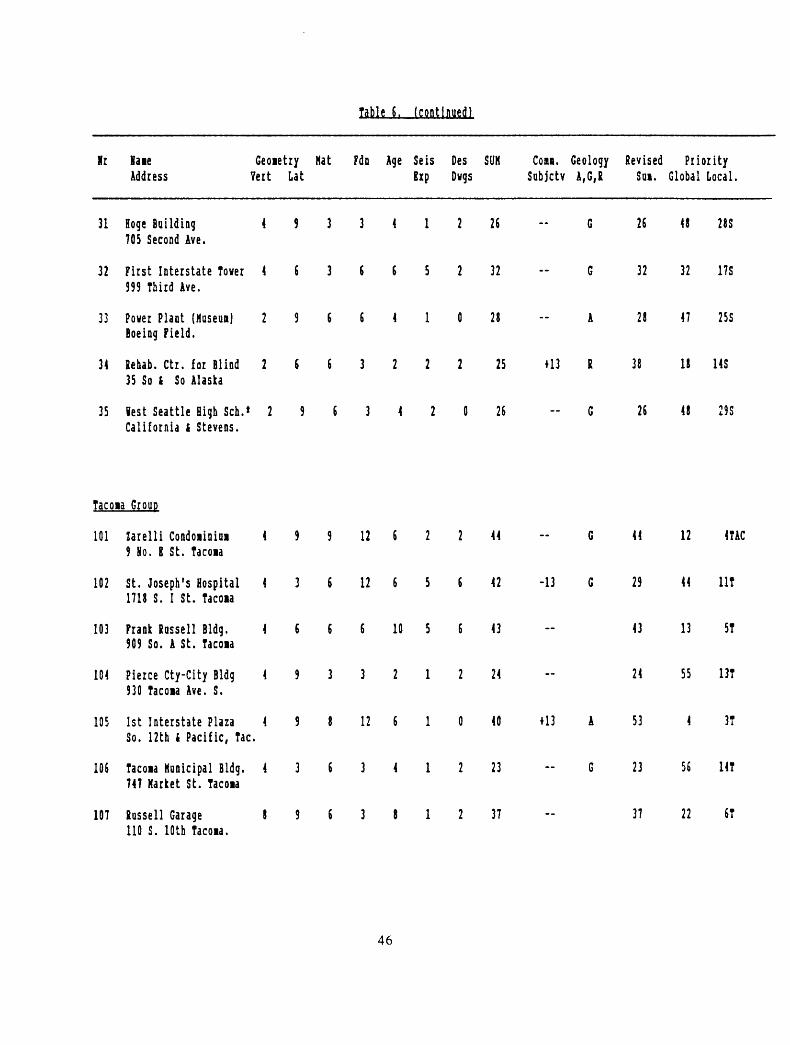
Table 6. (continued!
Hr Mate Geoietry Mat Fdn Age Seis Des SUM GOBI. Geology Revised Priority Address Vert Lat Kxp Dvgs Sobjctv A,G,B SQL Global Local.
31 Hoge Building 4 9 3 3 4 1 2 26 - G 26 48 28S 70S Second Ave.
32 First Interstate Tower 4 5 3 6 6 5 2 32 - G 32 32 ITS 999 Third Ave.
33 Power Plant (Huseui) 2 9 6 6 4 1 0 28 -- A 28 47 25S Boeing Field.
34 Rehab. Ctr. for Blind 2 6 5 3 2 2 2 25 +13 R 38 18 14S 35 So i So Alaska
35 lest Seattle High Sen.' 2 9 5 3 4 2 0 26 G 26 48 29S California S Stevens.
Tacoia Group
101 Zarelli Condoiinini 4 9 9 12 6 2 2 44 - G 44 12 4TAC 9 Ho. 8 St. Tacoia
102 St. Joseph's Hospital 4 3 6 12 6 5 6 42 -13 G 29 44 lit 1718 S. I St. Tacoia
103 Prank Russell Bldg. 4 6 6 6 10 5 6 43 -- 43 13 5T 909 So. A St. Tacoia
104 Pierce Cty-City Bldg 4 9 3 3 2 1 2 24 -- 24 55 13T 930 Tacoia Ave. S.
105 1st Interstate Plaza 4 9 8 12 6 1 0 40 +13 A 53 4 3T So. 12th i Pacific, Tac.
106 Tacoia Municipal Bldg. 4 3 6 3 4 1 2 23 G 23 56 14T 747 Market St. Tacoia
107 Russell Garage 8 9 6 3 8 1 2 37 -- 37 22 6T 110 S. 10th Tacoia.
46
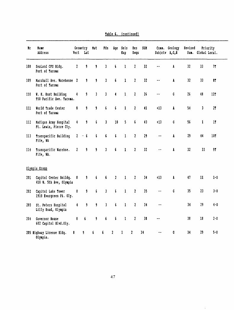
Table 6. (continued)
Hz
108
109
110
111
112
113
in
Haie Geoaetry Mat Fdn Age Seis Des SUM Coaa. Geology Address Vert Lat Exp Dvgs Subjctv A,G,R
SeaLand CFS Bldg. 2 9 9 3 6 1 2 32 APort of Tacoia
Marshall Ave. Varehouse 2 9 9 3 6 1 2 32 APort of Tacoia
¥. K. Rust Bonding 4 9 3 3 \ I 2 26 G950 Pacific Ave. Tacoia.
¥orld Trade Center 8 9 9 6 6 1 2 41 +13 APort of Tacoia
Madigan Arny Hospital 4 9 6 3 10 5 6 43 +13 GFt. Lewis, Pierce Cty.
Transpacific Building 2 - 6 6 6 6 1 2 29 - AFife, n
Transpacific Sarehse. 2 9 9 3 6 1 2 32 -- A
Revised Priority SQL Global Local.
32 33 7T
32 33 8T
26 48 12T
54 3 2T
56 1 IT
29 44 10T
32 33 9TFife, ¥A.
Olyapia Groop
201 Capitol Center Buildg. 8 9 6 6 2 1 2 34 +13 A 47 11 1-0 410 8. 5th Ave, Olyipia
202 Capitol Lake Tower 8 9 6 3 6 1 2 35 -- G 35 23 3-0 1910 Evergreen Pk. Oiy.
203 St. Peters Hospital 4 9 9 3 6 1 2 34 -- 34 29 4-0 Lilly Road, Olyipia
204 Governor Hoase 8 6 9 6 6 1 2 38 38 18 2-0 602 Capitol Blvd.Oly.
205 Highway License Bldg. 8 9 6 6 2 1 2 34 - G 34 29 5-0 Olyipia.
47
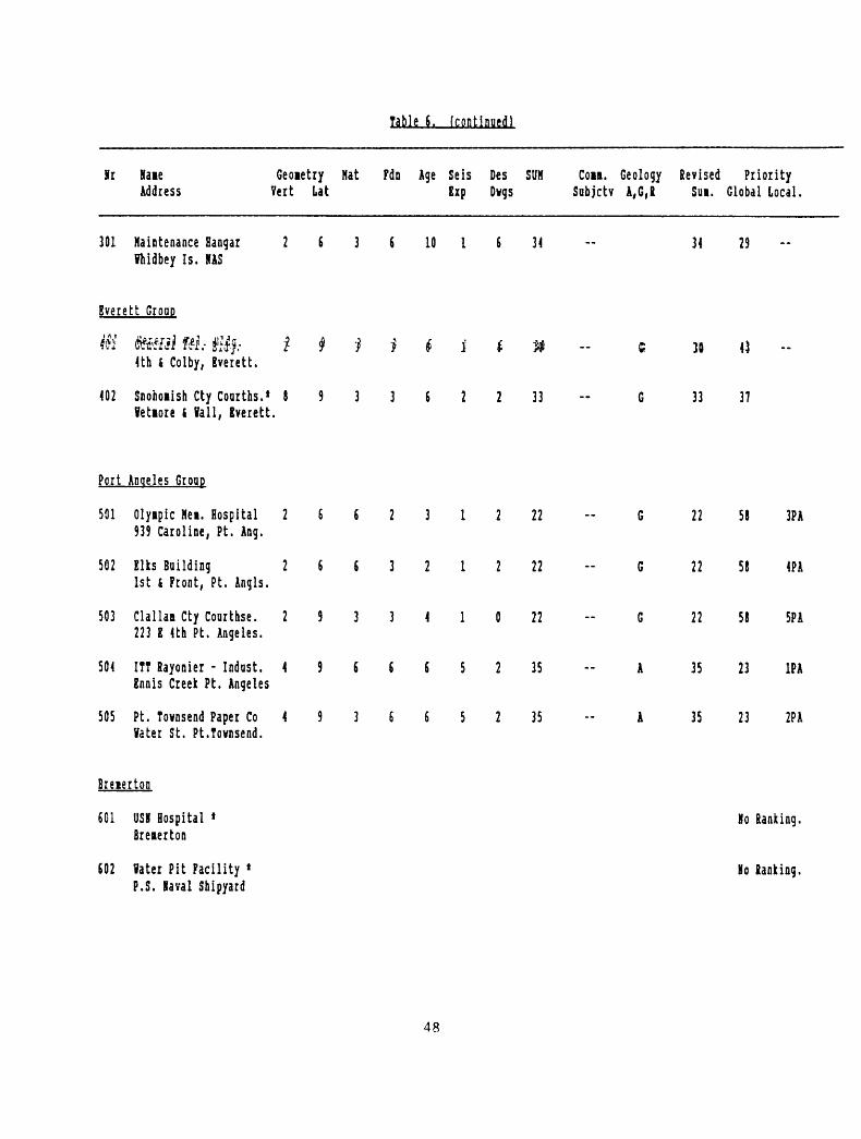
Table 6. (continued)
Sr Kaie Geoietry Hat Fdn Age Seis Des SUM Con. Geology Revised Priority Address Vert Lat Exp Dvgs Sabjctv A,G,£ Sui, Global Local,
301 Maintenance Hangar 2 6 3 6 10 1 8 31 - 34 29 -- fhidbey Is. HAS
Everett Groop
AK fcttiti i& fdj.- i # * * t i t n c H «Uh k Coiby, Everett.
402 Snohoiish Cty Courths.* 8 9 3 3 8 2 2 33 G 33 37 letiore t fall, Bverett.
Port Angeles Group
501 Olyipic Nei. Hospital 2 6 6 2 3 1 2 22 - G 22 58 3PA 939 Caroline, Pt. Ang.
502 Elks Building 2 6 8 3 2 1 2 22 - G 22 58 4PA 1st & Front, Pt. Angls.
503 Clallaa Cty Courthse. 2 9 3 3 4 1 0 22 - G 22 58 SPA 223 E Uh Pt. Angeles.
504 ITT Rayonier - Indust. 4 9 5 8 5 5 2 35 - A 35 23 1PA Ennis Creek Pt. Angeles
505 Pt. Townsend Paper Co 4 9 3 6 6 5 2 35 -- A 35 23 2PA later St. Pt.Tovnsend.
Breierton
601 USK Hospital * Mo Ranking. Breierton
802 later Pit Facility * Ho tanking. P.S. Iaval Shipyard
48

Table 6. (continoedl
Kr Kane Geonetry Hat Pdn Age Seis Des SUM Com. Geology Revised Priority Address Vert Lat Sip Dwgs Sabjctv A,G,R Sui. Global Local.
Bellinqhaa Groop
701 Ibatcoi Cty.Courthse. 8 9 5 3 2 1 2 31 -- 31 39 2BEL Bellinghas.
702 Lincoln Square 8 6 6 6 1 2 35 -- 35 23 IB 409 York Bellinghai
703 Leopold Hotel 8 9 3 3 4 2 2 31 R 31 39 3B 1224 CornMall, Bellbt.
704 Bond Ball 2 6 6 6 2 1 2 25 G 25 53 4B iestern ia. Univ.
Sose Instrumentation exists.
49

Table 7. Recommended Instrumentation Sites in Seattle/Bellevue1 '2.
Sugroup 1
Airborne Bldg. Newport Lane
Red LionDenny Bldg.Old Federal Office Bldg.Arlington North/South
Subgroup 5
Subgroup 2
Rainer Cold Storage Sears
EldeckMercer Canal Bldg. Boeing Field Pwr. Plant Kirstler Morse Boeing Engr. Bldg. King St. Station
Subgroup 6
Subgroup 4
Block 5 Gateway Tower
Westin Bldg.Seafirst 5th Ave. PlazaFirst Interstate CenterBay Vista TowerWatermark Tower84 UnionSeattle Trust Tower
World Trade Center (Tacoma) Capitol Center Bldg. (Olympic)
Crowne Plaza Hotel H.M. Jackson Bldg.
2 Union Square Westlake Project Bellevue Place Rainier Bank Place Vance Bldg. 4th &: Blanchard Bldg.
1. Buildings have been arranged within each subgroup in descending order of importance for instrumentation based upon both geotechnical and structural criteria.
2. It is recommended to instrument one building from each subgroup with multiple instruments. Instrumentation should be installed sequentially, according to subgroup number.
3. Building subgroups correspond to those on Tables 2 and 3.4. Subgroup 3, 7, and 8 are for single instruments and not included in this table.
50

EXISTING ACCELEROGRAPH STATIONS
FIG. 1
51

HISTORICAL SEISMICITY 1872 - 1988
FIG. 2
52

PROPOSED GROUND STATIONS
FIG. 3
53

123
122
SC
AL
E:
1 :
50
0,0
00
LE
GE
ND
AL
LU
VIU
M
GL
AC
IAL
D
EP
OS
ITS
RO
CK
EX
IST
ING
A
CC
EL
ER
OG
RA
PH
ST
AT
ION
S
A B
uild
ings
and
bri
dg
es (
U.S
.G.S
.)
4-
Bu
ild
ing
s
(oth
ers
)
NO
TE
S:
1.
Map
in
dic
ate
s
ge
ne
rali
zed
su
rfac
e g
eolo
gy.
2.
Bas
e m
ap
fro
m S
late
o
f W
as
hin
gto
n
top
og
rap
hic
m
ap
scal
e 1
: 50
0,O
OO
. 5
00
fo
ol
co
nto
ur
Inte
rval:
U
.S.
Geo
log
ical
Su
rvey.
3.
See
te
xt
for
refe
ren
ce
on
geo
log
y.
GE
NE
RA
LIZ
ED
SO
IL C
ON
DIT
ION
S
FIG
. 4
129
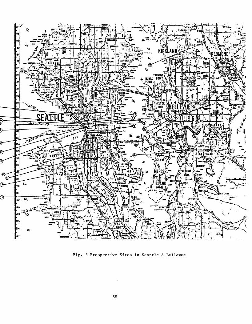
r--- VT.Mx lilt '.'icitiHn
*<~. -Knit^-r ..
*\Mc&.* MERCERr $*&«$#* -L^Ll*~**il* ^jZ^)*u~m IlklS :*^'«* l*"lil°r
Fig. 5 Prospective Sites in Seattle & Bellevue
55