GEOTECHNICAL INVESTIGATION GEOTECHNICAL INVESTIGATION BUDA ...

Report on Geotechnical Investigation
Midland Wastewater Pump Station Lot 799 Katharine Street, Bellevue
Prepared for Taliska Securities Pty Ltd
Project 88990.00 February 2018


Geotechnical Investigation, Midland Wastewater Pump Station 88990.00.R.001.Rev0 Lot 799 Katharine Street, Bellevue February 2018
Executive Summary
This report presents the results of a geotechnical investigation undertaken for a proposed wastewater
pump station (WWPS) at Lot 799 Katharine Street, Bellevue. The work was commissioned by Taliska
Securities Pty Ltd.
The purpose of the investigation was to assess the soil and groundwater conditions at two possible
locations for a proposed Type 10 WWPS founded at RL 5.0 m and associated storage tanks founded
at RL 8.6 m and assess the suitability for open cut excavation with spear point dewatering. The
investigation included the drilling of two boreholes, four cone penetration tests and laboratory testing
of selected samples. Site 1 is located approximately 260 m to the west of Site 2.
Summary of Ground Conditions at Site 1
Site Test
location Ground Conditions
Layer RLs
(m AHD)
Groundwater
RL
(m AHD)
Site 1 BH1
Dense clayey, sandy gravel 13.9 – 12.7
7.0
Hard sandy clay – possibly cemented 12.7 – 11.5
Very dense clayey sand – possibly
cemented 11.5 – 9.3
Hard sandy clay – possibly cemented 9.3 – 8.0
Very stiff sandy clay 8.0 – 3.4
Note: RLs are based on an interpolated ground surface RL of 14.0 m.
Summary of Ground Conditions at Site 2
Site Test
location Ground Conditions
Layer RLs
(m AHD)
Groundwater
RL
(m AHD)
Site 2 BH2
Hard sandy clay – possibly cemented 13.4 – 9.2
8.8
clayey sand 9.2 – 8.9
Very stiff sandy clay 8.9 – 7.5
Medium dense sand 7.5 – 6.3
Firm sandy clay 6.3 – 4.5
Note: RLs are based on an interpolated ground surface RL of 13.5 m.
Both sites are considered suitable for development with open cut excavation and dewatering. From a
geotechnical prospective, Site 1 is the preferred site, as conditions are considered to be suitable for
steeper batter angles, leading to a theoretical reduction in the excavation volume, stronger founding
conditions at the well base, and will likely require less dewatering due to a lower groundwater level
and less permeable soils.
In general, sandy clay and clayey sand are considered suitable for re-use as backfill around the well
structure, with sand typically used around pipes and near finished ground surface. Supervision is

Geotechnical Investigation, Midland Wastewater Pump Station 88990.00.R.001.Rev0 Lot 799 Katharine Street, Bellevue February 2018
recommended to assess the suitability of the provisions adopted during the earthworks to suitably
control the soil moisture and to regularly test compaction when using clayey filling.

Geotechnical Investigation, Midland Wastewater Pump Station 88990.00.R.001.Rev0 Lot 799 Katharine Street, Bellevue February 2018
Table of Contents
Page
1. Introduction..................................................................................................................................... 1
2. Site Description .............................................................................................................................. 2
3. Field Work Methods ....................................................................................................................... 4
4. Field Work Results ......................................................................................................................... 4
4.1 Ground Conditions ............................................................................................................... 4
4.2 Groundwater ........................................................................................................................ 5
5. Laboratory Testing ......................................................................................................................... 6
6. Proposed Development .................................................................................................................. 7
7. Comments ...................................................................................................................................... 7
7.1 Geotechnical Constraints and Notable Ground Conditions ................................................. 7
7.2 Excavation Conditions ......................................................................................................... 8
7.3 Slope Stability and Earth Retention Parameters ................................................................. 9
7.4 Foundation Preparation and Backfilling .............................................................................10
7.5 Foundation Design .............................................................................................................11
8. References ................................................................................................................................... 12
9. Limitations .................................................................................................................................... 12
Appendix A: About This Report
Drawings
Appendix B: Results of Field Work
Appendix C: Laboratory Testing Results

Page 1 of 13
Geotechnical Investigation, Midland Wastewater Pump Station 88990.00.R.001.Rev0 Lot 799 Katharine Street, Bellevue February 2018
Report on Geotechnical Investigation
Midland Wastewater Pump Station
Lot 799 Katharine Street, Bellevue
1. Introduction
This report presents the results of a geotechnical investigation undertaken for a proposed wastewater
pump station (WWPS) at Lot 799 Katharine Street, Bellevue. The investigation was commissioned in
an email dated 15 January 2018 from Robert Revy on behalf of Taliska Securities Pty Ltd and was
undertaken in accordance with Douglas Partners' proposal PER170504 dated 21 November 2017.
It is understood that two locations are being considered for a Type 10 WWPS and associated storage
tanks. The proposed well is to be founded at approximately RL 5.0 m AHD and storage tanks are to be
founded at RL 8.6 m. It is understood that the preferred construction methodology includes open cut
excavation with spear point dewatering.
The aim of this geotechnical investigation was to assess the subsurface conditions beneath both of the
sites and comment on:
• The ability to excavate encountered materials and safe batter slopes required.
• suitability of material for reuse as structural backfill.
• ground conditions including organic materials, rock or reactive soils.
• the possibility for perched aquifers.
• the potential for confined aquifers its impact on open cut.
• suitable bearing pressures for foundations and long and short term settlement.
• foundation preparation, if necessary.
• aggressiveness of soil for reinforced concrete.
• suitability of sheet piled or caisson construction techniques.
• suitability for open cut excavation with spear point dewatering.
• suggested construction and groundwater control methodologies, if open cut excavation is not
feasible.
The investigation included the drilling of two boreholes, four cone penetration tests and laboratory
testing of selected samples. The details of the field work are presented in this report, together with
comments and recommendations on the issues listed above.
It is understood that the results of this investigation will be used to select the site of the proposed
wastewater pump station. Additional investigations for acid sulphate soils and a dewatering
management plan are planned for the selected site only.

Page 2 of 13
Geotechnical Investigation, Midland Wastewater Pump Station 88990.00.R.001.Rev0 Lot 799 Katharine Street, Bellevue February 2018
2. Site Description
Two sites, approximately 260 m apart, are being considered for the development. Both are located on
the northern side off the Helena River. A tributary and associated alluvial plain have formed a channel
of relatively flat ground approximately 150 m wide near both sites. The flat ground was covered with
green grass and can be seen in Photo 2. Both sites are approximately 20 m north of the flat channel
and approximately 4 m higher in elevation.
Douglas Partners were provided with co-ordinates for the proposed development locations. A hand
held GPS was used to located the suggested test locations in the field.
Site Option 1 - at the time of the investigation, the proposed well location was in a tree line with steeply
sloping ground. It was not practical to drill at the proposed well location so the test was relocated
approximately 5 m to the north on flatter ground, as seen in Photo 1.
Photo 1: Site Option 1
Site Option 2 – at the time of the investigation, the location consisted of a gently sloping grass bank,
as seen on Photo 2. Survey data (received with the RFQ package) indicates that surface levels across
the site fall from RL 15 m to RL 10 m over 40 m in a southeast direction. The slope at the proposed
well location was too steep to drill so the test was moved to flatter ground approximately 10 m to the
north.
BH1

Page 3 of 13
Geotechnical Investigation, Midland Wastewater Pump Station 88990.00.R.001.Rev0 Lot 799 Katharine Street, Bellevue February 2018
Photo 2: Site Option 2
The Perth 1:50,000 Environmental Geological Survey sheet indicates that shallow sub surface
conditions beneath Site 1 consists of Guildford Formation. Site 2 is shown on the boundary between
Alluvium and the Guildford Formation. Geologically, Alluvium is considered to be a relatively young
deposit and thus exists near or at ground surface and overlies older geological units such as the
Guildford Formation. Site observations at Site 2, including landform features (sloping ground and
relatively flat ground) and the vegetation colour (as seen on Photo 2) indicates the change in geology.
The shallow sub surface conditions beneath Site 2 (i.e. test locations BH2, CPT5 and CPT6) are
considered to consist of the Guildford Formation.
Figure 1: Geological Information
Site 1
Site 2
BH2

Page 4 of 13
Geotechnical Investigation, Midland Wastewater Pump Station 88990.00.R.001.Rev0 Lot 799 Katharine Street, Bellevue February 2018
The Perth Groundwater Atlas (2004) indicates that the groundwater level was at RL 7 m AHD below
Site A and at RL 8 m AHD below Site B in May 2003.
3. Field Work Methods
The field work was undertaken on 31 January 2018, and comprised:
• drilling of two boreholes (BH1 at Site 1 and BH2 at Site 2); and
• cone penetration testing at four locations (CPT3 and 4 at Site 1 and CPT5 and 6 at Site 2).
The bores were drilled using a Geoprobe 7822DT drilling rig. Drilling using the push probe was started
at BH1 but reached refusal at shallow depth in hard conditions, and thus drilling was continued using
rotary and mud flush to target depths of 12.5 m (RL 1.5 m) at BH1 and 14.0 m (RL -0.5 m) at BH2.
Standard penetration tests (SPTs) were carried out at 1.5 m depth intervals to provide an indication of
the density of the soil and to collect samples for visual and tactile identification and laboratory testing.
Ground conditions were logged from recovered SPT samples in general accordance with AS 1726, by
a suitably experienced geotechnical engineer from Douglas Partners.
Following the completion of drilling, 50 mm diameter groundwater monitoring wells were installed in
boreholes to a depth of 9.5 m at BH1 and 12.0 m at BH2.
The CPTs were carried out by using a 36 mm diameter instrumented cone with a following 130 mm
long friction sleeve attached to rods of the same diameter, pushed continuously at a rate of 20 mm/sec
into the soil by hydraulic thrust from a ballasted truck mounted rig. Strain gauges in the cone and
sleeve measure resistance to penetration and this data allows assessment of the type and condition of
the materials penetrated. The CPT probe was pushed to a target depth of 11.0 m at CPT6, and
refusal above the target depth at the other locations. Upon withdrawing of the CPT probe, each
location was dipped to measure possible groundwater.
Test locations were determined using a GPS and are shown on Drawing 1 in Appendix A. Surface
elevations at each test location were interpolated from a survey provided by the client and are quoted
in metres above Australian Height Datum (AHD).
4. Field Work Results
4.1 Ground Conditions
Ground conditions to the proposed excavation levels of RL 5.0 m for the well and RL 8.6 m for the
storage tanks are summarised in Tables 1 and 2 (next page). Detailed logs of the ground conditions
and results of the field testing are presented in Appendix B, together with notes defining descriptive
terms and classification methods.

Page 5 of 13
Geotechnical Investigation, Midland Wastewater Pump Station 88990.00.R.001.Rev0 Lot 799 Katharine Street, Bellevue February 2018
Table 1: Summary of Ground Conditions at Site 1
Site Test
location Ground Conditions
Layer Levels
(m AHD)
Site 1
BH1
Dense clayey, sandy gravel 13.9 – 12.7
Hard sandy clay – possibly cemented 12.7 – 11.5
Very dense clayey sand – possibly cemented 11.5 – 9.3
Hard sandy clay – possibly cemented 9.3 – 8.0
Very stiff sandy clay 8.0 – 3.4
CPT3 Hard sandy clay – possibly cemented 14.0 - 12.2
CPT4 Hard sandy clay – possibly cemented 13.8 – 11.8
Very dense clayey sand – possibly cemented 11.8 – 11.4
Note: Table 1 RLs are based on an interpolated ground surface RL of 14.0 m, with an estimated accuracy of 0.5 m.
Table 2: Summary of Ground Conditions at Site 2
Site Test
location Ground Conditions
Layer Levels
(m AHD)
Site 2
BH2
Hard sandy clay – possibly cemented 13.4 – 9.2
clayey sand 9.2 – 8.9
Very stiff sandy clay 8.9 – 7.5
Medium dense sand 7.5 – 6.3
Firm to stiff sandy clay 6.3 – 2.3
CPT5A Dense gravelly sand 14.3 – 14.0
Hard sandy clay – possibly cemented 14.0 – 9.5
CPT6
Hard sandy clay – possibly cemented 11.0 – 9.0
Medium dense clayey sand 9.0 – 7.6
Very stiff sandy clay 7.6 – 3.2
Note: Table 2 RLs are based on an interpolated ground surface RL of 13.5 m, with an estimated accuracy of 0.5 m.
4.2 Groundwater
The use of muds was required during rotary drilling, and restricted groundwater observations during
drilling. Groundwater monitoring wells were installed following the completion of drilling. A return visit
to measure groundwater levels was carried out on 16 February 2018 (approximately two weeks
following drilling), and observations are summarised in Table 3 (next page).

Page 6 of 13
Geotechnical Investigation, Midland Wastewater Pump Station 88990.00.R.001.Rev0 Lot 799 Katharine Street, Bellevue February 2018
Table 3: Groundwater Observations on 16 February 2018
Location Groundwater depth
(m)
Ground Surface
(RL)
Groundwater Level
(RL)
BH1 6.96 14.0 7.04
BH2 4.69 13.5 8.81
Note: Table 3 RLs are based on ground surface levels interpolated from survey information.
Groundwater was measured at 1.0 m at CPT6, well above the groundwater levels observed in the
boreholes. This level possibly results from collapse of the test hole pushing water upwards or is an
indication of perched groundwater.
5. Laboratory Testing
A geotechnical laboratory testing programme was carried out by a NATA registered laboratory,
comprising the determination of:
• The particle size distribution (PSD) of six samples (three from each site);
• The Atterberg limits and linear shrinkage of four samples (two from each site); and
• The pH, chloride and sulphate analysis of six samples (three from each site).
Detailed test report sheets are given in Appendix C and the results are summarised in Table 4 (below)
and Table 5 (next page).
Table 4: Laboratory Test Results for Soil Characterisation
Test Depth
(m) Soil Description
Fines
(%)
Sand
(%)
Gravel
(%)
LL
(%)
PI
(%)
LS
(%)
BH1
0.8-1.3 Clayey, sandy
Gravel 26 27 47 37 22 9.0
3.0-3.23 Clayey sand 27 72 1 - - -
7.5-7.95 Sandy Clay 53 46 1 69 47 13.0
BH2
1.5-1.95 Sandy Clay 58 42 0 49 31 10.5
6.0-6.45 Sand with clay 11 89 0 - - -
7.5-7.95 Clay with sand 71 25 4 52 30 11.0
Notes: - Fines are particles smaller than 75 µm.
- LL: liquid limit - PI: plasticity index - LS: linear shrinkage ‘-‘ means ‘Not Tested’
To analyse the soil aggressivity, six samples were tested for pH, sulphate and chloride concentrations.
The results are provided in Table 5, along with the exposure classification following relevant
standards.

Page 7 of 13
Geotechnical Investigation, Midland Wastewater Pump Station 88990.00.R.001.Rev0 Lot 799 Katharine Street, Bellevue February 2018
Table 5: Test Results Regarding Soil and Aggressivity
Test Depth
(m) pH
Sulphate
SO4-2
(mg/kg)
Chloride
(mg/kg)
Exposure Classification[1]
Exposure Classification[2]
Soil
Conditions
A [3]
Soil
Conditions
B [4]
Soil
Conditions
A [3]
Soil
Conditions
B [4]
BH1
1.5-1.95 8.1 60 120 A1 N/A Non-
aggressive N/A
6.0-6.45 6.1 1,500 5,700 A1 N/A Non-
aggressive N/A
9.0-9.45 7.2 1,100 5,100 A1 N/A Non-
aggressive N/A
BH2
1.5-1.95 6.6 540 8,600 A1 N/A Non-
aggressive N/A
6.0-6.45 7.6 40 50 N/A A2 N/A Mild
9.0-9.45 7.0 20 250 A1 N/A Non-
aggressive N/A
Notes: [1]: Exposure Classification in accordance with AS 3600-2009.
[2]: Exposure Classification in accordance with AS 2159-2009.
[3]: Soil conditions A refer to high permeability soils (sand and gravel) which are within groundwater.
[4]: Soil conditions B refer to low permeability soils (silt and clay) and all soil above groundwater.
6. Proposed Development
It is understood that the proposed development includes the construction of a Type 10 wastewater
pumping station founded at RL 5.0 m AHD with associated storage tanks founded at RL 8.6 m AHD.
7. Comments
7.1 Geotechnical Constraints and Notable Ground Conditions
Based on field results as summarised in Section 4, both sites are considered suitable for development,
with open cut excavation and dewatering during construction.
It is recommended that construction is undertaken during the summer months. Experience of
earthworks within the Guildford Formation indicates rapid deterioration of the clayey subgrade during
wet periods, particularly under vehicle movements generally resulting in a pause of the earthworks to
limit further damage. Moisture conditioning clayey backfill material is also difficult during wet periods.
Site 1
From a geotechnical perspective, Site 1 is the preferred site as the conditions are considered to be
suitable for steeper batter angles, leading to a theoretical reduction in the excavation volume, stronger
founding conditions at the well base, and will likely require less dewatering due to a lower groundwater

Page 8 of 13
Geotechnical Investigation, Midland Wastewater Pump Station 88990.00.R.001.Rev0 Lot 799 Katharine Street, Bellevue February 2018
level and less permeable soils. The high SPT numbers recorded during drilling suggest that difficulty
could be expected if sheet pilling or installing dewatering spears above RL 6 m, unless pre-drilling is
implemented.
Site 2
Ground conditions include interbedded clayey sand, sandy clay and sand. Weaker material below
RL 6.3 m would require shallower batter angles and offer a lower design bearing capacity.
Encountered ground conditions at Site 2 also include a sand layer between RL 6.3 and RL 7.5 m,
which would likely increase groundwater pumping flows.
The Guildford Formation is predominately clayey soils and interbedded sand layers and thus has the
potential to collect rainwater as perched aquifers close to ground surface and to contain confined
aquifers in the interbedded sand layers. Such a sand layer was encountered in BH2 between 6.0 and
7.2 m. Groundwater monitoring results from February 2018 (refer to Section 4) are close to the
groundwater levels for May 2003 indicated in the Perth Groundwater Atlas (2004).
7.2 Excavation Conditions
A summary of anticipated equipment requirements is summarised in Table 6. The minimum
requirements are based on experience and ground density encountered at the test locations, and
suggested as a guide only. It should be noted that there are many other influencing factors that affect
excavation rates, such as the working zone (reach and depth), the quality of equipment, and the
operator’s ability.
Table 6: Excavation Equipment Requirement
Conditions SPT value Equipment (minimum
recommendation)
Medium dense to dense clayey
sand 10 - 50 20 tonne excavator
Very dense clayey sand 50 – Refusal
(in granular soil)
30 tonne excavator with toothed
bucket
Firm to very stiff sandy clay 8 – 30 20 tonne excavator
Hard sandy clay 30 - 40
(in cohesive soil)
30 tonne excavator with toothed
bucket
Cemented soil and low strength
rock
More than 40 in
cohesive soil or
refusal
Allow for ripping or rock breaker
Comparison of the site conditions summarised in Table 1 (Site 1) suggests that the excavation to the
base of the well would require a 30 tonne or heavier excavator with toothed bucket and the provision
for ripping harder materials (or using a rock breaker).

Page 9 of 13
Geotechnical Investigation, Midland Wastewater Pump Station 88990.00.R.001.Rev0 Lot 799 Katharine Street, Bellevue February 2018
Conditions summarised in Table 2 (Site 2) indicates the need of a 30 tonne excavator with toothed
bucket and the provision for ripping harder materials (or using a rock breaker) to RL 9 m with the use
of a smaller excavator possible below RL 9 m.
Based on groundwater observations, dewatering will be required during the excavation for the WWPS.
The extent of dewatering will depend on the construction method and the time of year when the
excavation is undertaken. Dewatering should continue until the well installation and backfilling
operations are well above current groundwater levels.
7.3 Slope Stability and Earth Retention Parameters
Excavations should be undertaken in accordance with the 'WA Code of Practice - Excavation'
(WorkSafe Western Australia, 2005). Personnel should not enter an unsupported excavation unless
considered safe to do so by a competent person as defined by the Code of Practice.
For unsupported excavations with suitable dewatering, a benched excavation could be constructed
using the parameters set out in Table 7.
Table 7: Recommended Parameters for Excavations
Conditions SPT value Safe Batter Slope (H:V) Batter Height
Medium dense to dense
clayey sand 10 - 50 1.5:1 <3m
Very dense clayey sand
(when dry)
50 – Refusal
(in granular soil) 1:1 <3m
Firm to stiff sandy clay 8 – 15 1.5:1 <2m
Very Stiff to Hard sandy
clay
15 - 40
(in cohesive
soil)
1:1 <3m
Cemented soil and low
strength rock
More than 40 in
cohesive soil or
refusal
0.75:1 <4m
Addition loads such as equipment and excavated spoil should be set back from the top of batters. A
site specific assessment of stability should be undertaken if loads are applied at the top of batters.
It is further noted that dewatering will be required for open cut excavation due to shallow groundwater,
as discussed in Section 7.7. If dewatering is compromised during construction, groundwater has the
capacity to potentially destabilise excavated batter slopes. In the event of failure of the dewatering
system, all works within or near open cut excavation should cease until dewatering has been
successfully restored. Following such an event, the existing batter slopes should be inspected by a
geotechnical engineer prior the commencement of further works.

Page 10 of 13
Geotechnical Investigation, Midland Wastewater Pump Station 88990.00.R.001.Rev0 Lot 799 Katharine Street, Bellevue February 2018
Should consideration be given to ground support to reduce the extent and volume of the excavation,
then secant continuous flight auger (CFA) piles may be feasible at the site. The drivability of sheet
piles and advancement of caissons through the hard very dense materials is likely to be restrictive.
Design Parameters for temporary and permanent retaining structures are suggested in Table 8.
Table 8: Soil Parameters for Earth Retaining Design
Soil Type
and Density
Soil Unit
Weight
Above Water
γ
(kN/m3)
Submerged
Soil Unit
Weight
γ’
(kN/m3)
Drained
Angle of
Friction
Φ’
(Degrees)
Undrained
Shear
Strength
Cu
(kPa)
Coefficient
of Earth
Pressure –
Active
Ka
Coefficient
of Earth
Pressure –
at Rest
Ko
Coefficient
of Earth
Pressure –
Passive
Kp
Compacted
Clayey
Sand/Sandy
Clay Filling
20 10 25 75 0.3 0.5 2.5
Compacted
Sand Filling 20 10 34 0 0.25 0.5 4.5
7.4 Foundation Preparation and Backfilling
Assuming that the earthworks are carried out in dry conditions, it is anticipated that minimal site
preparation will be required to provide a suitable founding material for the wet well and overflow
storage tanks. It is likely that the subgrade materials could become disturbed during the excavation of
overlying soils, thus it is recommended that the base is tested and if required compacted prior to the
construction of any footings.
Any residual groundwater inflow (assuming suitable dewatering previsions using wells or spears along
the perimeter of the excavation) should be manageable using pump and sumps from the base of the
excavation.
In general, sandy clay and clayey sand materials, are considered suitable for re-use as backfill around
the well structure. Clayey soils can be difficult to compact consistently, particularly in small areas,
however can be achieved when:
• large clods of clay are removed from the stockpile or broken down to less than 100 mm in size;
• the filling is moisture conditioned to within 2% of its optimum moisture content prior to placement;
and
• filling is placed in loose lift layers of less than 100 mm loose lift when using compactors less than
3 tonne in weight or less than 150 mm loose lift when using pad foot rollers heavier than 5 tonne.
Supervision of earthworks by an experienced person (such as a geotechnical engineer) is
recommended to control the soil moisture and regularly test compaction. Following AS3798, Level 1
(full time) supervision is recommended for all significant activities.

Page 11 of 13
Geotechnical Investigation, Midland Wastewater Pump Station 88990.00.R.001.Rev0 Lot 799 Katharine Street, Bellevue February 2018
Compaction control of clayey filling is typically carried out using a nuclear surface moisture-density
gauge, in accordance with AS1289.5.8.1. This test is limited to a depth of up to 300 mm and can lead
to time delays when waiting for results. Alternatively, compaction can be assessed by an experienced
geotechnical engineer with regular site inspections and in situ testing using a dynamic cone
penetration and periodically supported with nuclear density testing results.
Imported sand is commonly used around pipework, tanks and near the proposed surface. A Perth
sand penetrometer can be used for compaction control of sand. A target value of 10 blows per
300 mm penetration is recommended. Calibration testing can be carried out to amend the target value.
It is recommended that any calibrations are assessed by Douglas Partners and a suitable value
agreed before commencing with an amended target value.
7.5 Foundation Design
The hard conditions encountered at Site 1 at the proposed well base (RL 5) and the proposed storage
tanks (RL 8.6) are considered suitable for a design net bearing capacity of 150 kPa with an estimated
total settlement of less than 10 mm.
The hard conditions encountered at Site 2 at RL 8.6 (storage tanks) also offer a design net bearing
capacity of 150 kPa with and estimated total settlement of less than 10 mm. However, at Site 2 firm to
stiff clayey soil overlying loose sand were encountered below RL 5 (well base). It is suggested that a
design net bearing pressure for the well at Site 2 be limited to 100 kPa to limit estimated total
settlement to less than 20 mm, or 50 kPa to reduce total settlement to less than 10 mm.
The wet well should also be designed to resist hydrostatic pressure uplift. Parameters for the
compacted clayey backfill are provided in Table 9 to calculate the shaft resistance to uplift, if required.
Table 9: Soil Parameters for Shaft Resistance to Uplift
Soil Type and
Density
Soil Weight
Above Water
γ
(kN/m3)
Submerged Soil
Unit Weight
γ’
(kN/m3)
Drained Angle of
Friction
Φ’
(Degrees)
Friction Angle
between
backfilling and
pre-cast
concrete
Φ’
(Degrees)
Coefficient of
Earth Pressure –
at Rest
Ko
Compacted
Clayey
Sand/Sandy Clay
Filling
18 8 20 15 0.5
Compacted Sand
Filling 18 8 34 20 0.5

Page 12 of 13
Geotechnical Investigation, Midland Wastewater Pump Station 88990.00.R.001.Rev0 Lot 799 Katharine Street, Bellevue February 2018
8. References
• Australian Standard AS 1289.6.3.3-1999. Soil Strength and Consolidation Tests-Determination of
the Penetration Resistance of a Soil - Perth Sand Penetrometer Test
• Australian Standard AS 1289.6.3.2-1999, Soil Strength and Consolidation Tests-Determination of
the Penetration Resistance of a Soil - Dynamic Cone Penetrometer Test
• Australian Standard AS 3600-2009, Concrete Structures
• Australian Standard AS 1759-2009, Piling Design and Installation.
• Department of Environment, Perth Groundwater Atlas, Second Edition, December 2004
• Australian Standard AS 1726-2017, Geotechnical Site Investigation
• Code of Practice – Excavation, 2005, WorkSafe Western Australia
9. Limitations
Douglas Partners (DP) has prepared this report for this project at Lot 799 Katharine Street, Bellevue in
accordance with DP’s proposal PER170504 dated 21 November 2017 and acceptance received from
Taliska Securities Pty Ltd dated 15 January 2018. The work was carried out under DP’s Conditions of
Engagement. This report is provided for the exclusive use of Taliska Securities Pty Ltd for this project
only and for the purposes as described in the report. It should not be used by or relied upon for other
projects or purposes on the same or other site or by a third party. Any party so relying upon this report
beyond its exclusive use and purpose as stated above, and without the express written consent of DP,
does so entirely at its own risk and without recourse to DP for any loss or damage. In preparing this
report DP has necessarily relied upon information provided by the client and/or their agents.
The results provided in the report are indicative of the sub-surface conditions on the site only at the
specific sampling and/or testing locations, and then only to the depths investigated and at the time the
work was carried out. Sub-surface conditions can change abruptly due to variable geological
processes and also as a result of human influences. Such changes may occur after DP’s field testing
has been completed.
DP’s advice is based upon the conditions encountered during this investigation. The accuracy of the
advice provided by DP in this report may be affected by undetected variations in ground conditions
across the site between and beyond the sampling and/or testing locations.
This report must be read in conjunction with all of the attached and should be kept in its entirety
without separation of individual pages or sections. DP cannot be held responsible for interpretations
or conclusions made by others unless they are supported by an expressed statement, interpretation,
outcome or conclusion stated in this report.
This report, or sections from this report, should not be used as part of a specification for a project,
without review and agreement by DP. This is because this report has been written as advice and
opinion rather than instructions for construction.
Page 13 of 13
Geotechnical Investigation, Midland Wastewater Pump Station 88990.00.R.001.Rev0 Lot 799 Katharine Street, Bellevue February 2018
The contents of this report do not constitute formal design components such as are required, by the
Health and Safety Legislation and Regulations, to be included in a Safety Report specifying the
hazards likely to be encountered during construction and the controls required to mitigate risk. This
design process requires risk assessment to be undertaken, with such assessment being dependent
upon factors relating to likelihood of occurrence and consequences of damage to property and to life.
This, in turn, requires project data and analysis presently beyond the knowledge and project role
respectively of DP. DP may be able, however, to assist the client in carrying out a risk assessment of
potential hazards contained in the Comments section of this report, as an extension to the current
scope of works, if so requested, and provided that suitable additional information is made available to
DP. Any such risk assessment would, however, be necessarily restricted to the (geotechnical /
environmental / groundwater) components set out in this report and to their application by the project
designers to project design, construction, maintenance and demolition.
Douglas Partners Pty Ltd

Appendix A
About This Report Drawing

July 2010
Introduction These notes have been provided to amplify DP's report in regard to classification methods, field procedures and the comments section. Not all are necessarily relevant to all reports. DP's reports are based on information gained from limited subsurface excavations and sampling, supplemented by knowledge of local geology and experience. For this reason, they must be regarded as interpretive rather than factual documents, limited to some extent by the scope of information on which they rely. Copyright This report is the property of Douglas Partners Pty Ltd. The report may only be used for the purpose for which it was commissioned and in accordance with the Conditions of Engagement for the commission supplied at the time of proposal. Unauthorised use of this report in any form whatsoever is prohibited. Borehole and Test Pit Logs The borehole and test pit logs presented in this report are an engineering and/or geological interpretation of the subsurface conditions, and their reliability will depend to some extent on frequency of sampling and the method of drilling or excavation. Ideally, continuous undisturbed sampling or core drilling will provide the most reliable assessment, but this is not always practicable or possible to justify on economic grounds. In any case the boreholes and test pits represent only a very small sample of the total subsurface profile. Interpretation of the information and its application to design and construction should therefore take into account the spacing of boreholes or pits, the frequency of sampling, and the possibility of other than 'straight line' variations between the test locations. Groundwater Where groundwater levels are measured in boreholes there are several potential problems, namely: • In low permeability soils groundwater may
enter the hole very slowly or perhaps not at all during the time the hole is left open;
• A localised, perched water table may lead to an erroneous indication of the true water table;
• Water table levels will vary from time to time with seasons or recent weather changes. They may not be the same at the time of construction as are indicated in the report; and
• The use of water or mud as a drilling fluid will mask any groundwater inflow. Water has to be blown out of the hole and drilling mud must first be washed out of the hole if water measurements are to be made.
More reliable measurements can be made by installing standpipes which are read at intervals over several days, or perhaps weeks for low permeability soils. Piezometers, sealed in a particular stratum, may be advisable in low permeability soils or where there may be interference from a perched water table. Reports The report has been prepared by qualified personnel, is based on the information obtained from field and laboratory testing, and has been undertaken to current engineering standards of interpretation and analysis. Where the report has been prepared for a specific design proposal, the information and interpretation may not be relevant if the design proposal is changed. If this happens, DP will be pleased to review the report and the sufficiency of the investigation work. Every care is taken with the report as it relates to interpretation of subsurface conditions, discussion of geotechnical and environmental aspects, and recommendations or suggestions for design and construction. However, DP cannot always anticipate or assume responsibility for: • Unexpected variations in ground conditions.
The potential for this will depend partly on borehole or pit spacing and sampling frequency;
• Changes in policy or interpretations of policy by statutory authorities; or
• The actions of contractors responding to commercial pressures.
If these occur, DP will be pleased to assist with investigations or advice to resolve the matter.

July 2010
Site Anomalies In the event that conditions encountered on site during construction appear to vary from those which were expected from the information contained in the report, DP requests that it be immediately notified. Most problems are much more readily resolved when conditions are exposed rather than at some later stage, well after the event. Information for Contractual Purposes Where information obtained from this report is provided for tendering purposes, it is recommended that all information, including the written report and discussion, be made available. In circumstances where the discussion or comments section is not relevant to the contractual situation, it may be appropriate to prepare a specially edited document. DP would be pleased to assist in this regard and/or to make additional report copies available for contract purposes at a nominal charge. Site Inspection The company will always be pleased to provide engineering inspection services for geotechnical and environmental aspects of work to which this report is related. This could range from a site visit to confirm that conditions exposed are as expected, to full time engineering presence on site.

Aerial image obtained from Nearmap (flown 12 February 2018)
CLIENT: Taliska Securities Pty Ltd
Location of Site 1 and Site 2 PROJECT No: 88990.00
OFFICE: Perth Midland Wastewater Pump Station DRAWING No: 1
DATE: 21-02-2018 Lot 799 Katherine Street, Bellevue REVISION: A
750m 500m 250m 0m 1000m
Legend
Site location
Note: Scale is approximate.
Site 1
Site 2

Aerial image obtained from Nearmap (flown 12 February 2018)
Site 1 Test Location Plan PROJECT: 88990.00
Midland Wastewater Pump Station Drawing No: 2
Lot 799 Katherine Street, Bellevue REV: A
CLIENT: Taliska Securities Pty Ltd DATE: 21-02-2018
60m 40m 20m 0m 80m
Legend
Borehole Location
CPT Location Note: Scale is approximate.
BH1
CPT4
CPT3

Aerial image obtained from Nearmap (flown 12 February 2018)
Site 2 Test Location Plan PROJECT: 88990.00
Midland Wastewater Pump Station Drawing No: 3
Lot 799 Katherine Street, Bellevue REV: A
CLIENT: Taliska Securities Pty Ltd DATE: 21-02-2018
60m 40m 20m 0m 80m
Legend
Borehole Location
CPT Location Note: Scale is approximate.
BH2
CPT6
CPT5

Appendix B
Results of Field Work

May 2017
Description and Classification Methods The methods of description and classification of
soils and rocks used in this report are based on
Australian Standard AS 1726-1993, Geotechnical
Site Investigations Code. In general, the
descriptions include strength or density, colour,
structure, soil or rock type and inclusions.
Soil Types Soil types are described according to the
predominant particle size, qualified by the grading
of other particles present:
Type Particle size (mm)
Boulder >200
Cobble 63 - 200
Gravel 2.36 - 63
Sand 0.075 - 2.36
Silt 0.002 - 0.075
Clay <0.002
The sand and gravel sizes can be further
subdivided as follows:
Type Particle size (mm)
Coarse gravel 20 - 63
Medium gravel 6 - 20
Fine gravel 2.36 - 6
Coarse sand 0.6 - 2.36
Medium sand 0.2 - 0.6
Fine sand 0.075 - 0.2
The proportions of secondary constituents of soils
are described as:
Term Proportion Example
And Specify Clay (60%) and
Sand (40%)
Adjective 20 - 35% Sandy Clay
Slightly 12 - 20% Slightly Sandy
Clay
With some 5 - 12% Clay with some
sand
With a trace of 0 - 5% Clay with a trace
of sand
Definitions of grading terms used are:
• Well graded - a good representation of all
particle sizes
• Poorly graded - an excess or deficiency of
particular sizes within the specified range
• Uniformly graded - an excess of a particular
particle size
• Gap graded - a deficiency of a particular
particle size with the range
Cohesive Soils Cohesive soils, such as clays, are classified on the
basis of undrained shear strength. The strength
may be measured by laboratory testing, or
estimated by field tests or engineering
examination. The strength terms are defined as
follows:
Description Abbreviation Undrained shear strength
(kPa)
Very soft vs <12
Soft s 12 - 25
Firm f 25 - 50
Stiff st 50 - 100
Very stiff vst 100 - 200
Hard h >200
Cohesionless Soils Cohesionless soils, such as clean sands, are
classified on the basis of relative density, generally
from the results of standard penetration tests
(SPT), cone penetration tests (CPT) or dynamic
penetrometers (PSP). The relative density terms
are given below:
Relative Density
Abbreviation SPT N value
CPT qc value (MPa)
Very loose vl <4 <2
Loose l 4 - 10 2 -5
Medium
dense
md 10 - 30 5 - 15
Dense d 30 - 50 15 - 25
Very
dense
vd >50 >25

May 2017
Soil Origin It is often difficult to accurately determine the origin
of a soil. Soils can generally be classified as:
• Residual soil - derived from in-situ weathering
of the underlying rock;
• Transported soils - formed somewhere else
and transported by nature to the site; or
• Filling - moved by man.
Transported soils may be further subdivided into:
• Alluvium - river deposits
• Lacustrine - lake deposits
• Aeolian - wind deposits
• Littoral - beach deposits
• Estuarine - tidal river deposits
• Talus - scree or coarse colluvium
• Slopewash or Colluvium - transported
downslope by gravity assisted by water.
Often includes angular rock fragments and
boulders.

May 2017
Introduction These notes summarise abbreviations commonly
used on borehole logs and test pit reports.
Drilling or Excavation Methods C Core drilling
R Rotary drilling
SFA Spiral flight augers
NMLC Diamond core - 52 mm dia
NQ Diamond core - 47 mm dia
HQ Diamond core - 63 mm dia
PQ Diamond core - 81 mm dia
Water � Water seep
� Water level
Sampling and Testing A Auger sample
B Bulk sample
D Disturbed sample
E Environmental sample
U50 Undisturbed tube sample (50mm)
W Water sample
pp Pocket penetrometer (kPa)
PID Photo ionisation detector
PL Point load strength Is(50) MPa
S Standard Penetration Test
V Shear vane (kPa)
Description of Defects in Rock The abbreviated descriptions of the defects should
be in the following order: Depth, Type, Orientation,
Coating, Shape, Roughness and Other. Drilling
and handling breaks are not usually included on
the logs.
Defect Type
B Bedding plane
Cs Clay seam
Cv Cleavage
Cz Crushed zone
Ds Decomposed seam
F Fault
J Joint
Lam Lamination
Pt Parting
Sz Sheared Zone
V Vein
Orientation
The inclination of defects is always measured from
the perpendicular to the core axis.
h horizontal
v vertical
sh sub-horizontal
sv sub-vertical
Coating or Infilling Term
cln clean
co coating
he healed
inf infilled
stn stained
ti tight
vn veneer
Coating Descriptor
ca calcite
cbs carbonaceous
cly clay
fe iron oxide
mn manganese
slt silty
Shape
cu curved
ir irregular
pl planar
st stepped
un undulating
Roughness
po polished
ro rough
sl slickensided
sm smooth
vr very rough
Other
fg fragmented
bnd band
qtz quartz

May 2017
Graphic Symbols for Soil and Rock General
Soils
Sedimentary Rocks
Metamorphic Rocks
Igneous Rocks
Road base
Filling
Concrete
Asphalt
Topsoil
Peat
Clay
Conglomeratic sandstone
Conglomerate
Boulder conglomerate
Sandstone
Slate, phyllite, schist
Siltstone
Mudstone, claystone, shale
Coal
Limestone
Porphyry
Cobbles, boulders
Sandy gravel
Laminite
Silty sand
Clayey sand
Silty clay
Sandy clay
Gravelly clay
Shaly clay
Silt
Clayey silt
Sandy silt
Sand
Gravel
Talus
Gneiss
Quartzite
Dolerite, basalt, andesite
Granite
Tuff, breccia
Dacite, epidote

July 2010
Sampling Sampling is carried out during drilling or test pitting to allow engineering examination (and laboratory testing where required) of the soil or rock. Disturbed samples taken during drilling provide information on colour, type, inclusions and, depending upon the degree of disturbance, some information on strength and structure. Undisturbed samples are taken by pushing a thin-walled sample tube into the soil and withdrawing it to obtain a sample of the soil in a relatively undisturbed state. Such samples yield information on structure and strength, and are necessary for laboratory determination of shear strength and compressibility. Undisturbed sampling is generally effective only in cohesive soils. Test Pits Test pits are usually excavated with a backhoe or an excavator, allowing close examination of the in-situ soil if it is safe to enter into the pit. The depth of excavation is limited to about 3 m for a backhoe and up to 6 m for a large excavator. A potential disadvantage of this investigation method is the larger area of disturbance to the site. Large Diameter Augers Boreholes can be drilled using a rotating plate or short spiral auger, generally 300 mm or larger in diameter commonly mounted on a standard piling rig. The cuttings are returned to the surface at intervals (generally not more than 0.5 m) and are disturbed but usually unchanged in moisture content. Identification of soil strata is generally much more reliable than with continuous spiral flight augers, and is usually supplemented by occasional undisturbed tube samples. Continuous Spiral Flight Augers The borehole is advanced using 90-115 mm diameter continuous spiral flight augers which are withdrawn at intervals to allow sampling or in-situ testing. This is a relatively economical means of drilling in clays and sands above the water table. Samples are returned to the surface, or may be collected after withdrawal of the auger flights, but they are disturbed and may be mixed with soils from the sides of the hole. Information from the drilling (as distinct from specific sampling by SPTs or undisturbed samples) is of relatively low
reliability, due to the remoulding, possible mixing or softening of samples by groundwater. Non-core Rotary Drilling The borehole is advanced using a rotary bit, with water or drilling mud being pumped down the drill rods and returned up the annulus, carrying the drill cuttings. Only major changes in stratification can be determined from the cuttings, together with some information from the rate of penetration. Where drilling mud is used this can mask the cuttings and reliable identification is only possible from separate sampling such as SPTs. Continuous Core Drilling A continuous core sample can be obtained using a diamond tipped core barrel, usually with a 50 mm internal diameter. Provided full core recovery is achieved (which is not always possible in weak rocks and granular soils), this technique provides a very reliable method of investigation. Standard Penetration Tests Standard penetration tests (SPT) are used as a means of estimating the density or strength of soils and also of obtaining a relatively undisturbed sample. The test procedure is described in Australian Standard 1289, Methods of Testing Soils for Engineering Purposes - Test 6.3.1. The test is carried out in a borehole by driving a 50 mm diameter split sample tube under the impact of a 63 kg hammer with a free fall of 760 mm. It is normal for the tube to be driven in three successive 150 mm increments and the 'N' value is taken as the number of blows for the last 300 mm. In dense sands, very hard clays or weak rock, the full 450 mm penetration may not be practicable and the test is discontinued. The test results are reported in the following form. • In the case where full penetration is obtained
with successive blow counts for each 150 mm of, say, 4, 6 and 7 as:
4,6,7 N=13
• In the case where the test is discontinued before the full penetration depth, say after 15 blows for the first 150 mm and 30 blows for the next 40 mm as:
15, 30/40 mm

July 2010
The results of the SPT tests can be related empirically to the engineering properties of the soils. Dynamic Cone Penetrometer Tests / Perth Sand Penetrometer Tests Dynamic penetrometer tests (DCP or PSP) are carried out by driving a steel rod into the ground using a standard weight of hammer falling a specified distance. As the rod penetrates the soil the number of blows required to penetrate each successive 150 mm depth are recorded. Normally there is a depth limitation of 1.2 m, but this may be extended in certain conditions by the use of extension rods. Two types of penetrometer are commonly used. • Perth sand penetrometer - a 16 mm diameter
flat ended rod is driven using a 9 kg hammer dropping 600 mm (AS 1289, Test 6.3.3). This test was developed for testing the density of sands and is mainly used in granular soils and filling.
• Cone penetrometer - a 16 mm diameter rod with a 20 mm diameter cone end is driven using a 9 kg hammer dropping 510 mm (AS 1289, Test 6.3.2). This test was developed initially for pavement subgrade investigations, and correlations of the test results with California Bearing Ratio have been published by various road authorities.

TOPSOIL (Silty SAND) - dark grey-brown, fine to mediumgrained, silty sand topsoil with trace gravel, dry to moist.
Clayey Sandy GRAVEL - Dense, orange-brown, mediumplasticity, clayey sandy gravel, dry to moist.
- becoming orange-brown mottled red-brown from 0.8 mdepth.
Sandy Clay - Hard grey mottled red-brown, mediumplasticity, sandy clay.
- becoming grey mottled brown from 1.5 m depth.
Clayey SAND - very dense, brown, fine to mediumgrained, clayey sand with trace gravel, dry to moist.
Sandy CLAY - hard, grey, high plasticity, sandy clay, dry.
0.1
1.3
2.5
4.7
Typ
e
1413
1211
10
Depth(m)
1
2
3
4
RL
Wat
er
Dep
th
Sam
ple
Description
of
Strata Gra
phic
Log
Results &Comments
Sampling & In Situ Testing
1
2
3
4
CLIENT:PROJECT:LOCATION: Lot 799 Katharine Street, Bellevue, WA
SAMPLING & IN SITU TESTING LEGENDA Auger sample G Gas sample PID Photo ionisation detector (ppm)B Bulk sample P Piston sample PL(A) Point load axial test Is(50) (MPa)BLK Block sample Ux Tube sample (x mm dia.) PL(D) Point load diametral test Is(50) (MPa)C Core drilling W Water sample pp Pocket penetrometer (kPa)D Disturbed sample Water seep S Standard penetration testE Environmental sample Water level V Shear vane (kPa)
BORE No: BH1PROJECT No: 88990.00DATE: 31/1/2018SHEET 1 OF 3
DRILLER: National Geotech LOGGED: YC CASING:
Taliska SecuritiesProposed Waste Water Pump Station
REMARKS:
RIG: Geoprobe 7822DT
WATER OBSERVATIONS:
TYPE OF BORING:
Drilling method precluded groundwater observations
Push probe to 1.5 m then rotary mud flush
SURFACE LEVEL: 14.0 m AHD*EASTING: 407619NORTHING: 6469710DIP/AZIMUTH: 90°/--
BOREHOLE LOG
Dynamic Penetrometer Test(blows per 150mm)
5 10 15 20
Sand Penetrometer AS1289.6.3.3Cone Penetrometer AS1289.6.3.2
28,31,41N = 72
35,50,Rrefusal
19,20,27N = 47
D
D
D
S
S
S
0.2
0.8
1.3
1.5
1.95
3.0
3.23
4.5
4.95

Sandy CLAY - hard, grey, high plasticity, sandy clay, dry.(continued)
- becoming very stiff from 6.0 m depth.
- becoming grey mottled brown from 6.5 m depth.
- becoming grey mottled red-brown and brown from 7.0 mdepth.
- becoming grey, red-brown and brown from 9.0 m depth.
10.0
Typ
e
98
76
5
Depth(m)
6
7
8
9
RL
Wat
er
Dep
th
Sam
ple
Description
of
Strata Gra
phic
Log
Results &Comments
Sampling & In Situ Testing
6
7
8
9
CLIENT:PROJECT:LOCATION: Lot 799 Katharine Street, Bellevue, WA
SAMPLING & IN SITU TESTING LEGENDA Auger sample G Gas sample PID Photo ionisation detector (ppm)B Bulk sample P Piston sample PL(A) Point load axial test Is(50) (MPa)BLK Block sample Ux Tube sample (x mm dia.) PL(D) Point load diametral test Is(50) (MPa)C Core drilling W Water sample pp Pocket penetrometer (kPa)D Disturbed sample Water seep S Standard penetration testE Environmental sample Water level V Shear vane (kPa)
BORE No: BH1PROJECT No: 88990.00DATE: 31/1/2018SHEET 2 OF 3
DRILLER: National Geotech LOGGED: YC CASING:
Taliska SecuritiesProposed Waste Water Pump Station
REMARKS:
RIG: Geoprobe 7822DT
WATER OBSERVATIONS:
TYPE OF BORING:
Drilling method precluded groundwater observations
Push probe to 1.5 m then rotary mud flush
SURFACE LEVEL: 14.0 m AHD*EASTING: 407619NORTHING: 6469710DIP/AZIMUTH: 90°/--
BOREHOLE LOG
Dynamic Penetrometer Test(blows per 150mm)
5 10 15 20
Sand Penetrometer AS1289.6.3.3Cone Penetrometer AS1289.6.3.2
6,8,12N = 20
4,8,11N = 19
7,12,15N = 27
S
S
S
6.0
6.45
7.5
7.95
9.0
9.45
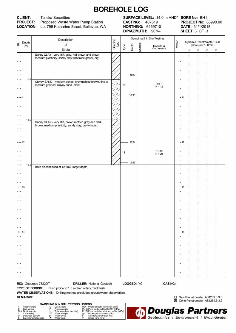
Sandy CLAY - very stiff, grey, red-brown and brown,medium plasticity, sandy clay with trace gravel, dry.
Clayey SAND - medium dense, grey mottled brown, fine tomedium grained, clayey sand, moist.
Sandy CLAY - very stiff, brown mottled grey and darkbrown, medium plasticity, sandy clay, dry to moist.
Bore discontinued at 12.5m (Target depth)
10.6
11.5
12.5
Typ
e
43
21
0
Depth(m)
11
12
13
14
RL
Wat
er
Dep
th
Sam
ple
Description
of
Strata Gra
phic
Log
Results &Comments
Sampling & In Situ Testing
11
12
13
14
CLIENT:PROJECT:LOCATION: Lot 799 Katharine Street, Bellevue, WA
SAMPLING & IN SITU TESTING LEGENDA Auger sample G Gas sample PID Photo ionisation detector (ppm)B Bulk sample P Piston sample PL(A) Point load axial test Is(50) (MPa)BLK Block sample Ux Tube sample (x mm dia.) PL(D) Point load diametral test Is(50) (MPa)C Core drilling W Water sample pp Pocket penetrometer (kPa)D Disturbed sample Water seep S Standard penetration testE Environmental sample Water level V Shear vane (kPa)
BORE No: BH1PROJECT No: 88990.00DATE: 31/1/2018SHEET 3 OF 3
DRILLER: National Geotech LOGGED: YC CASING:
Taliska SecuritiesProposed Waste Water Pump Station
REMARKS:
RIG: Geoprobe 7822DT
WATER OBSERVATIONS:
TYPE OF BORING:
Drilling method precluded groundwater observations
Push probe to 1.5 m then rotary mud flush
SURFACE LEVEL: 14.0 m AHD*EASTING: 407619NORTHING: 6469710DIP/AZIMUTH: 90°/--
BOREHOLE LOG
Dynamic Penetrometer Test(blows per 150mm)
5 10 15 20
Sand Penetrometer AS1289.6.3.3Cone Penetrometer AS1289.6.3.2
4,5,7N = 12
5,8,12N = 20
S
S
10.5
10.95
12.0
12.45

TOPSOIL (Sandy CLAY) - brown, sandy clay topsoil withsome roots, dry to moist.
Sandy CLAY - hard, brown mottled orange-brown, sandyclay, medium plasticity, with trace gravel, dry to moist.
- becoming grey-brown and brown from 3.0 m depth.
Clayey SAND - brown, medium to coarse grained, clayeysand.
Sandy CLAY - very stiff, brown and grey-brown, mediumplasticity, sandy clay, dry to moist.
0.1
4.3
4.6
Typ
e
1312
1110
9
Depth(m)
1
2
3
4
RL
Wat
er
Dep
th
Sam
ple
Description
of
Strata Gra
phic
Log
Results &Comments
Sampling & In Situ Testing
1
2
3
4
CLIENT:PROJECT:LOCATION: Lot 799 Katharine Street, Bellevue, WA
SAMPLING & IN SITU TESTING LEGENDA Auger sample G Gas sample PID Photo ionisation detector (ppm)B Bulk sample P Piston sample PL(A) Point load axial test Is(50) (MPa)BLK Block sample Ux Tube sample (x mm dia.) PL(D) Point load diametral test Is(50) (MPa)C Core drilling W Water sample pp Pocket penetrometer (kPa)D Disturbed sample Water seep S Standard penetration testE Environmental sample Water level V Shear vane (kPa)
BORE No: BH2PROJECT No: 88990.00DATE: 1/2/2018SHEET 1 OF 3
DRILLER: National Geotech LOGGED: YC CASING:
Taliska SecuritiesProposed Waste Water Pump Station
REMARKS:
RIG: Geoprobe 7822DT
WATER OBSERVATIONS:
TYPE OF BORING:
Drilling method precluded groundwater observations
Rotary mud flush
SURFACE LEVEL: 13.5 m AHD*EASTING: 407877NORTHING: 6469792DIP/AZIMUTH: 90°/--
BOREHOLE LOG
Dynamic Penetrometer Test(blows per 150mm)
5 10 15 20
Sand Penetrometer AS1289.6.3.3Cone Penetrometer AS1289.6.3.2
7,12,20N = 32
12,21,27N = 48
10,7,10N = 17
S
S
S
1.5
1.95
3.0
3.45
4.5
4.95

Sandy CLAY - very stiff, brown and grey-brown, mediumplasticity, sandy clay, dry to moist. (continued)
SAND - medium dense, light grey, fine to mediumgrained, sand with clay.
Sandy CLAY - firm, dark brown mottled grey, mediumplasticity, sandy clay.
- becoming stiff from 9.0 m depth.
6.0
7.2
Typ
e
87
65
4
Depth(m)
6
7
8
9
RL
Wat
er
Dep
th
Sam
ple
Description
of
Strata Gra
phic
Log
Results &Comments
Sampling & In Situ Testing
6
7
8
9
CLIENT:PROJECT:LOCATION: Lot 799 Katharine Street, Bellevue, WA
SAMPLING & IN SITU TESTING LEGENDA Auger sample G Gas sample PID Photo ionisation detector (ppm)B Bulk sample P Piston sample PL(A) Point load axial test Is(50) (MPa)BLK Block sample Ux Tube sample (x mm dia.) PL(D) Point load diametral test Is(50) (MPa)C Core drilling W Water sample pp Pocket penetrometer (kPa)D Disturbed sample Water seep S Standard penetration testE Environmental sample Water level V Shear vane (kPa)
BORE No: BH2PROJECT No: 88990.00DATE: 1/2/2018SHEET 2 OF 3
DRILLER: National Geotech LOGGED: YC CASING:
Taliska SecuritiesProposed Waste Water Pump Station
REMARKS:
RIG: Geoprobe 7822DT
WATER OBSERVATIONS:
TYPE OF BORING:
Drilling method precluded groundwater observations
Rotary mud flush
SURFACE LEVEL: 13.5 m AHD*EASTING: 407877NORTHING: 6469792DIP/AZIMUTH: 90°/--
BOREHOLE LOG
Dynamic Penetrometer Test(blows per 150mm)
5 10 15 20
Sand Penetrometer AS1289.6.3.3Cone Penetrometer AS1289.6.3.2
5,7,10N = 17
2,3,3N = 6
2,4,5N = 9
S
S
S
6.0
6.45
7.5
7.95
9.0
9.45

Sandy CLAY - firm, dark brown mottled grey, mediumplasticity, sandy clay. (continued)
Clayey SAND - loose grey, fine to medium grained, clayeysand.
- becoming brown from 12.2 m depth.
Bore discontinued at 14.0m (Target depth)
11.2
14.0
Typ
e
32
10
-1
Depth(m)
11
12
13
14
RL
Wat
er
Dep
th
Sam
ple
Description
of
Strata Gra
phic
Log
Results &Comments
Sampling & In Situ Testing
11
12
13
14
CLIENT:PROJECT:LOCATION: Lot 799 Katharine Street, Bellevue, WA
SAMPLING & IN SITU TESTING LEGENDA Auger sample G Gas sample PID Photo ionisation detector (ppm)B Bulk sample P Piston sample PL(A) Point load axial test Is(50) (MPa)BLK Block sample Ux Tube sample (x mm dia.) PL(D) Point load diametral test Is(50) (MPa)C Core drilling W Water sample pp Pocket penetrometer (kPa)D Disturbed sample Water seep S Standard penetration testE Environmental sample Water level V Shear vane (kPa)
BORE No: BH2PROJECT No: 88990.00DATE: 1/2/2018SHEET 3 OF 3
DRILLER: National Geotech LOGGED: YC CASING:
Taliska SecuritiesProposed Waste Water Pump Station
REMARKS:
RIG: Geoprobe 7822DT
WATER OBSERVATIONS:
TYPE OF BORING:
Drilling method precluded groundwater observations
Rotary mud flush
SURFACE LEVEL: 13.5 m AHD*EASTING: 407877NORTHING: 6469792DIP/AZIMUTH: 90°/--
BOREHOLE LOG
Dynamic Penetrometer Test(blows per 150mm)
5 10 15 20
Sand Penetrometer AS1289.6.3.3Cone Penetrometer AS1289.6.3.2
2,4,7N = 11
1,4,3N = 7
SPT samples split:12.0-12.2 & 12.2-12.45
7,5,2N = 7
S
S
S
10.5
10.95
12.0
12.45
13.5
13.95

July 2010
Introduction The Cone Penetration Test (CPT) is a sophisticated soil profiling test carried out in-situ. A special cone shaped probe is used which is connected to a digital data acquisition system. The cone and adjoining sleeve section contain a series of strain gauges and other transducers which continuously monitor and record various soil parameters as the cone penetrates the soils. The soil parameters measured depend on the type of cone being used, however they always include the following basic measurements • Cone tip resistance qc • Sleeve friction fs • Inclination (from vertical) i • Depth below ground z Figure 1: Cone Diagram The inclinometer in the cone enables the verticality of the test to be confirmed and, if required, the vertical depth can be corrected. The cone is thrust into the ground at a steady rate of about 20 mm/sec, usually using the hydraulic rams of a purpose built CPT rig, or a drilling rig. The testing is carried out in accordance with the Australian Standard AS1289 Test 6.5.1.
Figure 2: Purpose built CPT rig The CPT can penetrate most soil types and is particularly suited to alluvial soils, being able to detect fine layering and strength variations. With sufficient thrust the cone can often penetrate a short distance into weathered rock. The cone will usually reach refusal in coarse filling, medium to coarse gravel and on very low strength or better rock. Tests have been successfully completed to more than 60 m. Types of CPTs Douglas Partners (and its subsidiary GroundTest) owns and operates the following types of CPT cones:
Type Measures Standard Basic parameters (qc, fs, i & z) Piezocone Dynamic pore pressure (u) plus
basic parameters. Dissipation tests estimate consolidation parameters
Conductivity Bulk soil electrical conductivity (σ) plus basic parameters
Seismic Shear wave velocity (Vs), compression wave velocity (Vp), plus basic parameters
Strata Interpretation The CPT parameters can be used to infer the Soil Behaviour Type (SBT), based on normalised values of cone resistance (Qt) and friction ratio (Fr). These are used in conjunction with soil classification charts, such as the one below (after Robertson 1990)

July 2010
Figure 3: Soil Classification Chart DP's in-house CPT software provides computer aided interpretation of soil strata, generating soil descriptions and strengths for each layer. The software can also produce plots of estimated soil parameters, including modulus, friction angle, relative density, shear strength and over consolidation ratio. DP's CPT software helps our engineers quickly evaluate the critical soil layers and then focus on developing practical solutions for the client's project. Engineering Applications There are many uses for CPT data. The main applications are briefly introduced below: Settlement CPT provides a continuous profile of soil type and strength, providing an excellent basis for settlement analysis. Soil compressibility can be estimated from cone derived moduli, or known consolidation parameters for the critical layers (eg. from laboratory testing). Further, if pore pressure dissipation tests are undertaken using a piezocone, in-situ consolidation coefficients can be estimated to aid analysis.
Pile Capacity The cone is, in effect, a small scale pile and, therefore, ideal for direct estimation of pile capacity. DP's in-house program ConePile can analyse most pile types and produces pile capacity versus depth plots. The analysis methods are based on proven static theory and empirical studies, taking account of scale effects, pile materials and method of installation. The results are expressed in limit state format, consistent with the Piling Code AS2159. Dynamic or Earthquake Analysis CPT and, in particular, Seismic CPT are suitable for dynamic foundation studies and earthquake response analyses, by profiling the low strain shear modulus G0. Techniques have also been developed relating CPT results to the risk of soil liquefaction. Other Applications Other applications of CPT include ground improvement monitoring (testing before and after works), salinity and contaminant plume mapping (conductivity cone), preloading studies and verification of strength gain. Figure 4: Sample Cone Plot

CONE PENETRATION TEST CPT 03Page 1 of 1
CLIENT: Taliska Securities
PROJECT: Proposed Waste Water Pump Station
LOCATION: Lot 799 Katharine Street, Bellevue, WA
REDUCED LEVEL: 14.0m
COORDINATES: 407614E 6469705N
DATE 31/01/2018
PROJECT No: 88990
REMARKS: Surface level interpolated from site option planDry to 1.8 m
File: P:\88990.00 - BELLEVUE, Lot 799 Katharine Street\4.0 Field Work\CPT\88990 - CPT 03.CP5Cone ID: Probedrill Type: EC24
ConePlot Version 5.9.2© 2003 Douglas Partners Pty Ltd
0
1
2
3
4
5
6
7
8
9
10
11
12
Depth(m)
0
1
2
3
4
5
6
7
8
9
10
11
12
Depth(m)
0 10 20 30 40 50
0.0 1.0 2.0 3.0 4.0 5.0
Cone Resistanceqc (MPa)
0 50 100 150 200 250 300 350 400 450 500
0 5 10 15 20 25 30 35 40 45 50
Sleeve Frictionfs (kPa)
0 5 10 15 20
Inclinationi (°)
0.0 1.0 2.0 3.0 4.0 5.0
Friction RatioRf (%)
Soil Behaviour Type
CLAY with some GRAVELLY SAND: Hard
Terminated at 1.8m due to refusalEnd at 1.80m qc = 39.2 1.80

CONE PENETRATION TEST CPT 04Page 1 of 1
CLIENT: Taliska Securities
PROJECT: Proposed Waste Water Pump Station
LOCATION: Lot 799 Katharine Street, Bellevue, WA
REDUCED LEVEL: 13.8 m
COORDINATES: 407611E 6469700N
DATE 31/01/2018
PROJECT No: 88990
REMARKS: Surface level interpolated from site option planDry to 2.4 m
File: P:\88990.00 - BELLEVUE, Lot 799 Katharine Street\4.0 Field Work\CPT\88990 - CPT 04.CP5Cone ID: Probedrill Type: EC24
ConePlot Version 5.9.2© 2003 Douglas Partners Pty Ltd
0
1
2
3
4
5
6
7
8
9
10
11
12
Depth(m)
0
1
2
3
4
5
6
7
8
9
10
11
12
Depth(m)
0 10 20 30 40 50
0.0 1.0 2.0 3.0 4.0 5.0
Cone Resistanceqc (MPa)
0 50 100 150 200 250 300 350 400 450 500
0 5 10 15 20 25 30 35 40 45 50
Sleeve Frictionfs (kPa)
0 5 10 15 20
Inclinationi (°)
0.0 1.0 2.0 3.0 4.0 5.0
Friction RatioRf (%)
Soil Behaviour Type
CLAY and SAND / CLAYEY SAND: Hard
SAND / CLAYEY SAND and GRAVELLYSAND: Very Dense. Terminated at 2.4 m dueto refusalEnd at 2.40m qc = 46.5
1.97
2.40

CONE PENETRATION TEST CPT 05Page 1 of 1
CLIENT: Taliska Securities
PROJECT: Proposed Waste Water Pump Station
LOCATION: Lot 799 Katharine Street, Bellevue, WA
REDUCED LEVEL: 14.1 m
COORDINATES: 407863E 6469798N
DATE 31/01/2018
PROJECT No: 88990
REMARKS: Surface level interpolated from site option planDry to 3.8 m
File: P:\88990.00 - BELLEVUE, Lot 799 Katharine Street\4.0 Field Work\CPT\88990 - CPT 05.CP5Cone ID: Probedrill Type: EC24
ConePlot Version 5.9.2© 2003 Douglas Partners Pty Ltd
0
1
2
3
4
5
6
7
8
9
10
11
12
Depth(m)
0
1
2
3
4
5
6
7
8
9
10
11
12
Depth(m)
0 10 20 30 40 50
0.0 1.0 2.0 3.0 4.0 5.0
Cone Resistanceqc (MPa)
0 50 100 150 200 250 300 350 400 450 500
0 5 10 15 20 25 30 35 40 45 50
Sleeve Frictionfs (kPa)
0 5 10 15 20
Inclinationi (°)
0.0 1.0 2.0 3.0 4.0 5.0
Friction RatioRf (%)
Soil Behaviour Type
GRAVELLY SAND with some SAND: Dense toVery Dense
CLAY with some SAND / CLAYEY SAND: Hard
Terminated at 3.9 m due to refusalEnd at 3.92m qc = 13.6
0.61
3.92

CONE PENETRATION TEST CPT 05APage 1 of 1
CLIENT: Taliska Securities
PROJECT: Proposed Waste Water Pump Station
LOCATION: Lot 799 Katharine Street, Bellevue, WA
REDUCED LEVEL: 14.3 m
COORDINATES: 407863E 6469800N
DATE 31/01/2018
PROJECT No: 88990
REMARKS: Surface level interpolated from site option planDry to 4.8 m
File: P:\88990.00 - BELLEVUE, Lot 799 Katharine Street\4.0 Field Work\CPT\88990 - CPT 05A.CP5Cone ID: Probedrill Type: EC24
ConePlot Version 5.9.2© 2003 Douglas Partners Pty Ltd
0
1
2
3
4
5
6
7
8
9
10
11
12
Depth(m)
0
1
2
3
4
5
6
7
8
9
10
11
12
Depth(m)
0 10 20 30 40 50
0.0 1.0 2.0 3.0 4.0 5.0
Cone Resistanceqc (MPa)
0 50 100 150 200 250 300 350 400 450 500
0 5 10 15 20 25 30 35 40 45 50
Sleeve Frictionfs (kPa)
0 5 10 15 20
Inclinationi (°)
0.0 1.0 2.0 3.0 4.0 5.0
Friction RatioRf (%)
Soil Behaviour Type
SAND with some GRAVELLY SAND: MediumDense to Very Dense
CLAY with some SAND / CLAYEY SAND: Hard
Terminated at 4.8 m due to refusalEnd at 4.84m qc = 43.3
0.35
4.84

CONE PENETRATION TEST CPT 06Page 1 of 1
CLIENT: Taliska Securities
PROJECT: Proposed Waste Water Pump Station
LOCATION: Lot 799 Katharine Street, Bellevue, WA
REDUCED LEVEL: 11.0
COORDINATES: 407888E 6469780N
DATE 31/01/2018
PROJECT No: 88990
REMARKS: Surface level interpolated from the site option plangroundwater measred after test at 1.0 m
File: P:\88990.00 - BELLEVUE, Lot 799 Katharine Street\4.0 Field Work\CPT\88990 - CPT 06.CP5Cone ID: Probedrill Type: EC24
ConePlot Version 5.9.2© 2003 Douglas Partners Pty Ltd
0
1
2
3
4
5
6
7
8
9
10
11
12
Depth(m)
0
1
2
3
4
5
6
7
8
9
10
11
12
Depth(m)
0 10 20 30 40 50
0.0 1.0 2.0 3.0 4.0 5.0
Cone Resistanceqc (MPa)
0 50 100 150 200 250 300 350 400 450 500
0 5 10 15 20 25 30 35 40 45 50
Sleeve Frictionfs (kPa)
0 5 10 15 20
Inclinationi (°)
0.0 1.0 2.0 3.0 4.0 5.0
Friction RatioRf (%)
Soil Behaviour Type
CLAY with some SAND / CLAYEY SAND: Hard
SILTY SAND / SANDY SILT and SAND:Medium Dense
SILTY CLAY / CLAYEY SILT: Very Stiff to Hard
CLAY with some SILTY CLAY / CLAYEY SILT:Very Stiff
SAND with some CLAYEY/SAND: MediumDense
CLAY with some SILTY CLAY / CLAYEY SILT:Stiff to Very Stiff
SAND with some CLAYEY/SAND: Loose toMedium Dense
Terminated at target depth of 11.0 m.End at 11.00m qc = 10.6
1.97
3.43
3.95
7.85
8.71
10.04
11.00

Appendix C
Laboratory Testing Results

LABORATORY REPORT
Job Number: 18-02077
Revision: 00
ADDRESS: Liquid Labs WA Date: 16 February 2018
4/96 Briggs Street
Welshpool WA 6106
ATTENTION: Matt Van Herk
DATE RECEIVED: 9/02/2018
YOUR REFERENCE: LLS/18
PURCHASE ORDER:
APPROVALS:
REPORT COMMENTS:
This report is issued by Analytical Reference Laboratory (WA) Pty Ltd
Samples are analysed on an as received basis unless otherwise noted.
METHOD REFERENCES:
Methods prefixed with "ARL" are covered under NATA Accreditation Number: 2377
Methods prefixed with "PM" are covered under NATA Accreditation Number: 2561
ARL No. 138 pH in Soil and Biosolid
ARL No. 306 Chloride in Soil and Sediment by Discrete Analyser
ARL No. 302 Sulphate in Soil and Sediment by Discrete Analyser
ARL GROUP
46-48 Banksia Road, Welshpool, Western Australia 6106
Telephone: 08 6253 4444 Facsimile: 08 6253 4440 www.arlwa.com.au www.promicro.com.au
Page 1 of 2

LABORATORY REPORT
Liquid Labs WA
ARL Job No: 18-02077 Revision: 00 Date: 16 February 2018
Misc. Inorganics in Soil
Sample No: LOR UNITS 18-02077-1 18-02077-2 18-02077-3 18-02077-4 18-02077-5
Sample Description: BH1 (1.5-1.95) BH1 (6.0-6.45) BH1 (9.0-9.45) BH2 (1.5-1.95) BH2 (6.0-6.45)
Sample Date:
pH 0.1 pH units 8.1 6.1 7.2 6.6 7.6
Chloride 10 mg/kg 60 1,500 1,100 540 40
Sulphate 10 mg/kg 120 5,700 5,100 8,600 50
Misc. Inorganics in Soil
Sample No: LOR UNITS 18-02077-6
Sample Description: BH2 (9.0-9.45)
Sample Date:
pH 0.1 pH units 7.0
Chloride 10 mg/kg 20
Sulphate 10 mg/kg 250
Result Definitions
LOR Limit of Reporting [NT] Not Tested [ND] Not Detected at indicated Limit of Reporting
* Denotes test not covered by NATA Accreditation
FOR MICROBIOLOGICAL TESTING - The data in this report may not be representative of a lot, batch or other samples and may not necessarily justify the acceptance
or rejection of a lot or batch, a product recall or support legal proceedings. Tests are not routinely performed as duplicates unless specifically requested. Changes
occur in the bacterial content of biological samples. Samples should be examined as soon as possible after collection, preferably within 6 hrs and must be stored at 4
degrees Celsius or below. Samples tested after 24 hrs cannot be regarded as satisfactory because of temperature abuse and variations.
ARL GROUP
46-48 Banksia Road, Welshpool, Western Australia 6106
Telephone: 08 6253 4444 Facsimile: 08 6253 4440 www.arlwa.com.au www.promicro.com.au
Page 2 of 2

Client Ticket No. S1333
Client Address Report No. LLS18/601 _1_PSDPI
Project Sample No. LLS18/601
Sampling Location Sampled By Client
Sample Identification
Sampling Method Preparation Method AS 1289.1.1 / WA 105.1
Sample History Wet or Dry Sieved Dry Sieved
Sieve Size (mm) Percent Passing Sieve (%)
75.0
37.5 100
19.0 93
9.5 73
4.75 70
2.36 53
1.18 50
0.600 46
0.425 44
0.300 41
0.150 33
0.075 26
AS 1289.3.1.1 AS 1289.3.2.1 AS 1289.3.3.1
Mould Length (mm) Condition of Dried Specimen
37 15 22 9.0 125 250 Cracked Curled
Comments:
Approved Signatory
Accredited for compliance with ISO/IEC 17025 - Testing Name M. van Herk
Accreditation No. 19872 Function Laboratory Manager
This document may not be reproduced except in full Issue Date 19-February-2018
SOIL CLASSIFICATION - TEST REPORTIn accordance with AS 1289.3.6.1, 2.1.1, 3.1.1, 3.2.1, 3.3.1, 3.4.1
Linear Shrinkage (%)Plasticity Index (%)Plastic Limit (%)Liquid Limit (%)
Taliska Securities
Proposed Waste Water Pump Station
Lot 799 Katherine Street, Bellevue WA
Shrinkage Specimen Details
BH1 0.8-1.3m
Tested as received
Air Dried
-
AS 1289.3.4.1
PARTICLE SIZE DISTRIBUTION - ANALYSIS BY SIEVINGAS 1289.3.6.1
CONSISTENCY LIMITS
0
10
20
30
40
50
60
70
80
90
100
0.0 0.1 1.0 10.0 100.0
Particle Size (mm)
%PA
SSIN
G
LLWA/TECH/Forms/Testing/Soils/AS_1289.2.1.1,3.6.1,3.1.1-3.4.1/Soil_Classification/Test_Report/REV001/SEP17 Page 1 of 1

Client Ticket No. S1333
Client Address Report No. LLS18/603 _1_PSD
Project Sample No. LLS18/603
Sampling Location Sampled By Client
Sample Identification
Sampling Method Preparation Method AS 1289.1.1 / WA 105.1
Sample History Wet or Dry Sieved Dry Sieved
Sieve Size (mm) Percent Passing Sieve (%)
75.0
37.5
19.0
9.5
4.75 100
2.36 99
1.18 92
0.600 74
0.425 63
0.300 51
0.150 33
0.075 27
AS 1289.3.1.1 AS 1289.3.2.1 AS 1289.3.3.1
Mould Length (mm) Condition of Dried Specimen
- - - - 125 250 Cracked Curled
Comments:
Approved Signatory
Accredited for compliance with ISO/IEC 17025 - Testing Name M. van Herk
Accreditation No. 19872 Function Laboratory Manager
This document may not be reproduced except in full Issue Date 19-February-2018
SOIL CLASSIFICATION - TEST REPORTIn accordance with AS 1289.3.6.1, 2.1.1, 3.1.1, 3.2.1, 3.3.1, 3.4.1
Linear Shrinkage (%)Plasticity Index (%)Plastic Limit (%)Liquid Limit (%)
Taliska Securities
Proposed Waste Water Pump Station
Lot 799 Katherine Street, Bellevue WA
Shrinkage Specimen Details
BH1 3.0-3.23m
Tested as received
Air Dried
-
AS 1289.3.4.1
PARTICLE SIZE DISTRIBUTION - ANALYSIS BY SIEVINGAS 1289.3.6.1
CONSISTENCY LIMITS
0
10
20
30
40
50
60
70
80
90
100
0.0 0.1 1.0 10.0 100.0
Particle Size (mm)
%PA
SSIN
G
LLWA/TECH/Forms/Testing/Soils/AS_1289.2.1.1,3.6.1,3.1.1-3.4.1/Soil_Classification/Test_Report/REV001/SEP17 Page 1 of 1

Client Ticket No. S1333
Client Address Report No. LLS18/605 _1_PSDPI
Project Sample No. LLS18/605
Sampling Location Sampled By Client
Sample Identification
Sampling Method Preparation Method AS 1289.1.1 / WA 105.1
Sample History Wet or Dry Sieved Dry Sieved
Sieve Size (mm) Percent Passing Sieve (%)
75.0
37.5
19.0
9.5
4.75 100
2.36 99
1.18 88
0.600 82
0.425 79
0.300 75
0.150 63
0.075 53
AS 1289.3.1.1 AS 1289.3.2.1 AS 1289.3.3.1
Mould Length (mm) Condition of Dried Specimen
69 22 47 13.0 125 250 Cracked Curled
Comments:
Approved Signatory
Accredited for compliance with ISO/IEC 17025 - Testing Name M. van Herk
Accreditation No. 19872 Function Laboratory Manager
This document may not be reproduced except in full Issue Date 19-February-2018
SOIL CLASSIFICATION - TEST REPORTIn accordance with AS 1289.3.6.1, 2.1.1, 3.1.1, 3.2.1, 3.3.1, 3.4.1
Linear Shrinkage (%)Plasticity Index (%)Plastic Limit (%)Liquid Limit (%)
Taliska Securities
Proposed Waste Water Pump Station
Lot 799 Katherine Street, Bellevue WA
Shrinkage Specimen Details
BH1 7.5-7.95m
Tested as received
Air Dried
-
AS 1289.3.4.1
PARTICLE SIZE DISTRIBUTION - ANALYSIS BY SIEVINGAS 1289.3.6.1
CONSISTENCY LIMITS
0
10
20
30
40
50
60
70
80
90
100
0.0 0.1 1.0 10.0 100.0
Particle Size (mm)
%PA
SSIN
G
LLWA/TECH/Forms/Testing/Soils/AS_1289.2.1.1,3.6.1,3.1.1-3.4.1/Soil_Classification/Test_Report/REV001/SEP17 Page 1 of 1

Client Ticket No. S1333
Client Address Report No. LLS18/607 _1_PSDPI
Project Sample No. LLS18/607
Sampling Location Sampled By Client
Sample Identification
Sampling Method Preparation Method AS 1289.1.1 / WA 105.1
Sample History Wet or Dry Sieved Dry Sieved
Sieve Size (mm) Percent Passing Sieve (%)
75.0
37.5
19.0
9.5
4.75
2.36 100
1.18 96
0.600 88
0.425 83
0.300 78
0.150 67
0.075 58
AS 1289.3.1.1 AS 1289.3.2.1 AS 1289.3.3.1
Mould Length (mm) Condition of Dried Specimen
49 18 31 10.5 125 250 Cracked Curled
Comments:
Approved Signatory
Accredited for compliance with ISO/IEC 17025 - Testing Name M. van Herk
Accreditation No. 19872 Function Laboratory Manager
This document may not be reproduced except in full Issue Date 19-February-2018
SOIL CLASSIFICATION - TEST REPORTIn accordance with AS 1289.3.6.1, 2.1.1, 3.1.1, 3.2.1, 3.3.1, 3.4.1
Linear Shrinkage (%)Plasticity Index (%)Plastic Limit (%)Liquid Limit (%)
Taliska Securities
Proposed Waste Water Pump Station
Lot 799 Katherine Street, Bellevue WA
Shrinkage Specimen Details
BH2 1.5-1.95m
Tested as received
Air Dried
-
AS 1289.3.4.1
PARTICLE SIZE DISTRIBUTION - ANALYSIS BY SIEVINGAS 1289.3.6.1
CONSISTENCY LIMITS
0
10
20
30
40
50
60
70
80
90
100
0.0 0.1 1.0 10.0 100.0
Particle Size (mm)
%PA
SSIN
G
LLWA/TECH/Forms/Testing/Soils/AS_1289.2.1.1,3.6.1,3.1.1-3.4.1/Soil_Classification/Test_Report/REV001/SEP17 Page 1 of 1

Client Ticket No. S1333
Client Address Report No. LLS18/608 _1_PSD
Project Sample No. LLS18/608
Sampling Location Sampled By Client
Sample Identification
Sampling Method Preparation Method AS 1289.1.1 / WA 105.1
Sample History Wet or Dry Sieved Dry Sieved
Sieve Size (mm) Percent Passing Sieve (%)
75.0
37.5
19.0
9.5
4.75
2.36 100
1.18 93
0.600 56
0.425 33
0.300 21
0.150 14
0.075 11
AS 1289.3.1.1 AS 1289.3.2.1 AS 1289.3.3.1
Mould Length (mm) Condition of Dried Specimen
- - - - 125 250 Cracked Curled
Comments:
Approved Signatory
Accredited for compliance with ISO/IEC 17025 - Testing Name M. van Herk
Accreditation No. 19872 Function Laboratory Manager
This document may not be reproduced except in full Issue Date 19-February-2018
SOIL CLASSIFICATION - TEST REPORTIn accordance with AS 1289.3.6.1, 2.1.1, 3.1.1, 3.2.1, 3.3.1, 3.4.1
Linear Shrinkage (%)Plasticity Index (%)Plastic Limit (%)Liquid Limit (%)
Taliska Securities
Proposed Waste Water Pump Station
Lot 799 Katherine Street, Bellevue WA
Shrinkage Specimen Details
BH2 6.0-6.45m
Tested as received
Air Dried
-
AS 1289.3.4.1
PARTICLE SIZE DISTRIBUTION - ANALYSIS BY SIEVINGAS 1289.3.6.1
CONSISTENCY LIMITS
0
10
20
30
40
50
60
70
80
90
100
0.0 0.1 1.0 10.0 100.0
Particle Size (mm)
%PA
SSIN
G
LLWA/TECH/Forms/Testing/Soils/AS_1289.2.1.1,3.6.1,3.1.1-3.4.1/Soil_Classification/Test_Report/REV001/SEP17 Page 1 of 1

Client Ticket No. S1333
Client Address Report No. LLS18/609 _1_PSDPI
Project Sample No. LLS18/609
Sampling Location Sampled By Client
Sample Identification
Sampling Method Preparation Method AS 1289.1.1 / WA 105.1
Sample History Wet or Dry Sieved Dry Sieved
Sieve Size (mm) Percent Passing Sieve (%)
75.0
37.5
19.0
9.5
4.75 100
2.36 96
1.18 91
0.600 85
0.425 83
0.300 81
0.150 77
0.075 71
AS 1289.3.1.1 AS 1289.3.2.1 AS 1289.3.3.1
Mould Length (mm) Condition of Dried Specimen
52 22 30 11.0 125 250 Cracked Curled
Comments:
Approved Signatory
Accredited for compliance with ISO/IEC 17025 - Testing Name M. van Herk
Accreditation No. 19872 Function Laboratory Manager
This document may not be reproduced except in full Issue Date 19-February-2018
SOIL CLASSIFICATION - TEST REPORTIn accordance with AS 1289.3.6.1, 2.1.1, 3.1.1, 3.2.1, 3.3.1, 3.4.1
Linear Shrinkage (%)Plasticity Index (%)Plastic Limit (%)Liquid Limit (%)
Taliska Securities
Proposed Waste Water Pump Station
Lot 799 Katherine Street, Bellevue WA
Shrinkage Specimen Details
BH2 7.5-7.95m
Tested as received
Air Dried
-
AS 1289.3.4.1
PARTICLE SIZE DISTRIBUTION - ANALYSIS BY SIEVINGAS 1289.3.6.1
CONSISTENCY LIMITS
0
10
20
30
40
50
60
70
80
90
100
0.0 0.1 1.0 10.0 100.0
Particle Size (mm)
%PA
SSIN
G
LLWA/TECH/Forms/Testing/Soils/AS_1289.2.1.1,3.6.1,3.1.1-3.4.1/Soil_Classification/Test_Report/REV001/SEP17 Page 1 of 1