Report on Accident to Fast Helicharters India Pvt. Ltd. Helicopter ...
53
1 FINAL REPORT ON ACCIDENT TO FAST HELICHARTERS INDIA PVT. LTD. HELICOPTER BELL 206 B III VT-TBA AT GODHRA (GUJARAT) ON 29/08/2012 1. Helicopter Type : BELL 206 B III Nationality : INDIAN Registration : VT - TBA 2. Owner/ Operator : FAST HELICHARTERS INDIA PVT. LTD. 3. Pilot – in –Command : Holder of CPL(H) Extent of injuries : Nil 4. Co-Pilot : NIL Extent of injuries : N/A 5. Place of Accident : GODHRA (GUJARAT) 6. Coordinates of Accident Site : 22-46-94 (N), 073-37-652 (E) 7. Last point of Departure : MORBI (GUJARAT ) 8. Intended place of Landing : GODHRA (GUJARAT) 9. Date & Time of Accident : 29 Aug 2012 0430 UTC (Approx.) 10. Passengers on Board : 4 Extent of Injuries : NIL 11. Phase of Operation : Landing 12. Type of Accident : During Landing the Helicopter Toppled Over (ALL TIMINGS IN THE REPORT ARE IN UTC)
Transcript of Report on Accident to Fast Helicharters India Pvt. Ltd. Helicopter ...

1
FINAL REPORT ON ACCIDENT TO FAST HELICHARTERS INDIA PVT. LTD. HELICOPTER BELL 206 B III VT-TBA AT GODHRA (GUJARAT) ON
29/08/2012
1. Helicopter
Type : BELL 206 B III
Nationality : INDIAN
Registration : VT - TBA
2. Owner/ Operator : FAST HELICHARTERS INDIA PVT. LTD.
3. Pilot – in –Command : Holder of CPL(H)
Extent of injuries : Nil
4. Co-Pilot : NIL Extent of injuries : N/A
5. Place of Accident : GODHRA (GUJARAT)
6. Coordinates of Accident Site : 22-46-94 (N),
073-37-652 (E)
7. Last point of Departure : MORBI (GUJARAT )
8. Intended place of Landing : GODHRA (GUJARAT)
9. Date & Time of Accident : 29 Aug 2012 0430 UTC (Approx.)
10. Passengers on Board : 4 Extent of Injuries : NIL
11. Phase of Operation : Landing 12. Type of Accident : During Landing the Helicopter
Toppled Over
(ALL TIMINGS IN THE REPORT ARE IN UTC)
2
SUMMARY
On 29/08/2012 M/s Fast Helicharters India Pvt. Ltd. Helicopter Bell 206 B III VT-
TBA (Sl. No. 4224) was operating a charter flight from Morbi to Godhra (Gujarat).
Previous to the day of accident, the helicopter did a night stop at Morbi. The AME had
refueled the helicopter as per the advice of the PIC and the programme. The following
day, the helicopter was released by the AME for flight at around 0130 UTC. The
helicopter was fully serviceable as no defect was reported by the PIC on the previous
sector.
At around 0230 UTC the PIC repositioned the helicopter for the passengers boarding.
04 passengers were boarded on the helicopter with rotors running. Thereafter, the
helicopter took off for Godhra at around 0245 UTC. The enroute flight was uneventful.
The helicopter reached overhead the landing site, a cemented helipad in the middle of an
open ground. Thereafter the PIC carried out an aerial reconnaissance and commenced
descent for landing. At approx. 300 feet, after crossing the obstruction, the helicopter
experienced a sink and lost height considerably. The PIC tried to control the helicopter,
however in the process; the helicopter contacted the ground (37 meters away from
helipad) on the rear portion of the right skid and subsequently, rolled over. There was no
fire after the accident. All the 05 occupants on the helicopter escaped unhurt.
The Ministry of Civil Aviation constituted a committee of inquiry to investigate the
cause of the accident under Aircraft (Investigation of Accidents and Incidents), Rules
2012 comprising of Sh. Yash Pall as Chairman and Sh. A X Joseph and Capt. JPS Kniggar
as members.

3
1. FACTUAL INFORMATION
1.1 History of the flight.
The M/s Fast Helicharters helicopter Bell 206 B III, Reg. No. VT-TBA was chartered
by Satsang Samiittee, Ahmadabad, for operations in Gujarat from 25/08/2012 to
29/08/2012. Prior to the accident flight, the helicopter did the entire operations
uneventfully. The helicopter was flown by a single pilot. The Co-Pilot controls were
removed to facilitate a passenger to occupy the front seat. Helicopter Bell 206 B III VT-
TBA was operating the last leg of the charter, on 29/08/2012, and the flight was from
Morbi to Godhra. During night halt, the helicopter was refueled, as per instructions of the
PIC, in the evening by the AME / authorized person. The Pre-Flight Checks of the
helicopter were carried out on the following morning, as per the scope of his
authorization and the helicopter was released for flying. The helicopter was fully
serviceable as no defect had been reported by the PIC on the previous sector. The Tech
Log was completed in respect of Pre-Flight Checks and refueling /oil upliftment etc. The
Load and Trim sheet was prepared by the PIC for 03 passengers on board, however, 04
passengers boarded the helicopter. Fresh / New Load & Trim Sheet was not prepared.
At around 0230 UTC the PIC repositioned the helicopter for the passengers boarding.
Before the helicopter was switched off, the passengers boarded the helicopter with the
rotors running. The passengers boarded the helicopter without any security check and
passenger briefing. Though, the flight was planned with 03 passengers, actually 04
passengers boarded the helicopter. The PIC without recalculating the power
requirements and change in Centre of Gravity position, took off from Morbi for Godhra at
0245 UTC.
During the 1Hr 45 minutes of flight, the PIC co-ordinated with the enroute Air Traffic
Control Units (Rajkot & Vadodara) for obtaining the latest weather updates and
continued the flight to Godhra. On reaching, the PIC made a large circle to identify the

4
landing site, assess the helipad (concrete) area, obstructions around the helipad, winds
and decided upon the approach direction before commencing the descent.
After crossing the high-tension wires with sufficient clearance, the helicopter
continued the approach. The PIC mentioned that he had observed the Main Rotor and
engine indicator showing 97% rpm(within normal operational limit 97 to 100 % ) He
further stated that after crossing the wires, sink was experienced. To arrest the sink he
came up on collective and noticed that the main rotor and engine rpm indicator
decreased and stabilized between 97% and 90 %. Subsequently he lowered the
collective to regain the rpm. The PIC assessing the situation to be as one of the governor
failure (engine underspeed) decided to carry out landing with forward speed. He further
mentioned that the approach was undershooting and that the helicopter would arrive
short of the helipad, if he did not make any corrections/adjustments to the flight path.
The PIC did not make any adjustments, to the forward speed and rate of descent of the
helicopter, to cater for the undershoot. At approximately 25 feet above ground, the PIC
applied collective in an attempt to reduce the rate of descent and forward speed. Seeing
that the rate of descent was not decreasing at the expected/desire rate, he applied full
collective and attempted to land with forward speed. The helicopter yawed and banked
to the starboard (right) close to the ground and impacted the ground on the rear portion
of the right skid with a right bank followed by the left skid digging into the ground and
the helicopter toppling over. The Main Rotors cut the tail-boom of the helicopter and got
dislodged from the mast. The Main Rotor Hub along with rotor flew away and was found
at a distance.
All the 05 occupants on board the helicopter, escaped unhurt. There was no fire
after the accident.

5
1.2 Injuries to persons.
1.3 Damage to Helicopter.
The helicopter sustained substantial damage. Examination of the helicopter wreckage
revealed no airframe pre-impact anomalies. All observed fractures were consistent with
overload fractures occurring at impact.
Details of damages:
a) The Main Rotor Blades had hit tail boom and both separated from the main
structure.
b) Main rotor blades were broken, fuselage was smashed, cockpit interior was
generally broken, (instrument panel was intact, Central Warning Panel (CWP) and
the various gauges were generally intact).
c) The tail rotor head and the blades were attached to the TGB when the tailboom
separated from the fuselage. The entire section was not available for inspection,
as the same had been taken away by the by-standers, therefore the Vertical Fin,
Tail Gear Box and Tail Drive Shaft were missing.
d) The left passenger door and crew door were completely destroyed. The nose
section including, pitot head, control pedestal, instrument panel etc after hitting
the ground were damaged. The helicopter battery compartment and battery were
damaged.
e) After hitting the ground, the Main Rotor mast sheared off the main rotor hub
along with blades and they were separated from the helicopter and were found
some distance away. The associated main rotor pitch change links were broken,
one of the main rotor blades was bent inward apparently due to impact, the hub
was not damaged.
INJURIES CREW PASSENGERS OTHERS
FATAL Nil Nil Nil
SERIOUS Nil Nil NiL
MINOR/None 01 04 ----

6
f) After impacting with the ground the rear skid pierced the bottom surface and
ruptured the main fuel tank.
1.4 Other damage: Nil 1.5 Personnel information: 1.5.1 Pilot – in – Command: Name : Holder of DGCA Licence
AGE : 45 years
Licence : CPL ( H )
Date of Issue : 05/05/2008
Valid up to : 04/05/2013
Category : Helicopter
Class : Single Engine Land
Endorsements as PIC : Alouette III/Chetak, Bell 206 B3
Date of Med. Exam. : 19/06/2012
Med. Exam valid upto : 18/12/2012
FRTO License No. : Valid
Date of issue : 05/05/2008
Valid up to : 04/05/2013
Total flying experience : 2372:35 hrs
Last flown on type : 27/08/2012
Total Hrs on type : 226 hrs 15 mts
Total flying experience during last 180 Days : 68:45 hrs
Total flying experience during last 90 Days : 36:00 hrs
Total flying experience during last 30 Days : 10:50 hrs
Total flying experience during last 07 Days : 05:50 hrs
Total flying experience during last 24 Hours : NIL

7
Scrutiny of the PIC log book, shows no record of any Flight Duty Time Limitation
violation. He was not involved in any Serious Incident/Accident in the past. At the time of
accident he was not current on all ancillary trainings. The PIC had not undergone the
simulator training as required by DGCA CAR Section 7, Series B Part XIV for helicopter
pilots.
1.6 Aircraft information: Construction:
HELICOPTER DESCRIPTION
Bell 206 B III is single pilot, five place, single engine, light helicopter with a two-
blade semi rigid main rotor, and a tail rotor that provides directional control.

8
Dimensions in Feet
The airframe consists of a semimonocoque fuselage with metal and fiberglass
covering; an aluminum-alloy monocoque tail-boom that supports the vertical fin, fixed
horizontal stabilizer, tail rotor, and tail rotor drive train; and aerodynamically shaped
couplings and fairings to protect all roof mounted components. The primary load-carrying
structures are two built in cabin bulkheads, a vertical control tunnel from the floor to the
cabin roof, and a pair of longitudinal beams in the cabin roof.
Landing gear is tubular skid type made of aluminum alloy. Optional pop-out or
fixed floats are available.
POWER PLANT
Bell 206 B III is powered by a single Allison 250-C20J engine. Maximum output is
420 SHP (313 kW), but due to transmission limits, the engine is flat rated to 317 SHP
(236 kw). The engine consists of a multistage axial-centrifugal-flow compressor, a single
combustion chamber, a two-stage gas producer turbine, and a two-stage power turbine
which supplies the output power of the engine. The engine is coupled to the transmission
through a freewheeling unit and main driveshaft.

9
Air is supplied to the engine through intakes on each side of the transmission
particle separator / sand –filter, which is installed to protect the engine from the sand
ingress into the engine.
The power turbine and gas producer tachometer generators are mounted on the
front of the engine on the left and right sides respectively. The starter / generator is
located on the right side. A turbine outlet temperature harness relays temperature
measurements to an indicator on the instrument penal. An ENG OUT warning light on the
caution panel illuminates when the gas producer tachometer RPM falls below a preset
level.
The anti-icing system directs hot compressor discharge air over the compressor
inlet guide vanes and front bearing support hub. The system is controlled by the ENGINE
DEICING switch on the pedestal.
The compressor wash system directs a spray of water toward the center of the
engine bellmouth. The spray fitting is mounted on the particle separator and the tubing
is routed to the left side of the helicopter for easy access to an outside water source.
An hourmeter mounted in the battery compartment operates in conjunction with
the engine RPM sensor. It gives an accumulative total of engine running time.
A start counter mounted on the engine records total starts, counting one start
each time ignition system is energized.
FUEL SYSTEM
The fuel system consists of a single bladder type fuel cell located in the aft
passenger seat bench with a capacity of 91 gallons (344 liters). The cell has been
reinforced to withstand a 50 foot drop test.

10
ROTOR SYSTEMS
MAIN ROTOR
The main rotor is a two-bladed, semirigid system. The blades are composed of
aluminum alloy parts. The hub is an underslung feathering-axis type, with six bearings
that require grease. It consists primarily of a yoke fitted onto a splined trunnion and
secured with pillow blocks; a pitch horn and grip assembly attached to each arm of the
yoke with a tension / torsion strap; and a blade-latch mechanism located between the
upper and lower tangs of each grip assembly.
TAIL ROTOR
The tail rotor is a two-bladed, semirigid rotor system mounted on the left side of
the tail-boom. The all-metal blades incorporate spherical pitch change bearings. Rotor
flapping is allowed by a delta hinge for stability during hovering turns and forward flight.
DUAL TACHOMETER
The dual tachometer indicates percentage of main rotor RPM (Nr) on the inner
scale and power turbine RPM (N2) of engine on the outer scale.
ROTOR LOW RPM CAUTION LIGHT
The ROTOR LOW RPM caution light will illuminate if rotor RPM drops below
approximately 90%.
RPM AUDIO WARNING

11
An audio warning signal will sound in the pilot and co-pilot headsets when main
rotor RPM decreases below 90% (simultaneous with LOW ROTOR RPM caution light
illumination).
ELECTRICAL SYSTEM
The electrical system is a 28 volt direct current, negative ground system. Power is
supplied by a 30 volt, 150 ampere starter – generator (derated to 105 amperes) and by a
24 volt, 13 ampere-hour nickel-cadmium battery located in the nose compartment. The
starter- generator serves a dual purpose as starter and main generator. A GEN FAIL
caution light (if installed) advises pilot of a failed generator.
The engine may be started from battery power or by connecting an external 28 V
DC power source to the power receptacle in the nose.
The ignition system consists of a single ignitor plug and an ignition exciter box.
The engine starter switch is located on the pilot’s collective stick.
The battery temperature is monitored by thermal switches mounted under the
battery case. The BATTERY TEMP caution light (amber) illuminates when the battery
temperature is above normal and the BATTERY HOT warning light (red) illuminates when
battery temperature is excessively high.
The instrument penal has integral white lights supplied by 5 Vdc power. All other
lighting is 28 Vdc white lighting.
Three position lights are installed – one on each side of horizontal stabilizer and
one on end of tail-boom. A red anti-collision strobe light is located on top of tail fin.
Bell 206 helicopter VT-TBA S/N 4224 was manufactured in 1992. The Helicopter
VT-TBA was initially registered under the ownership of M/s Trans Bharat Aviation and

12
thereafter it was registered with M/s Fast Helicharters India Pvt Ltd., Certificate of
registration No. 3006/3, dated 21.06.2011 under category ’A’.
The certificate of airworthiness Number 2415 under “Normal category” sub-
division “passenger” was issued by DGCA on 20.08.1999 and specified minimum
operating crew as 01. The maximum authorized all up weight is 1451.50 kgs. The C of A
is valid up to 07.12.2012. The Helicopter was flown with Aero Mobile Licence No. A-
93/01 and is valid up till 31.12.2013. This helicopter was operated under Non scheduled
operator’s permit No. 10-2011 and was valid up to 18.12.2013. This Bell 206 helicopter
VT-TBA has logged 4732.09 A/F Hrs as on 27.08.2012 accident date.
The Bell 206 helicopter and its Engine are being maintained as per the
maintenance programme consisting of calendar period based maintenance and flying
Hours/ Cycles based maintenance as per maintenance programme approved by Regional
Airworthiness Office, Mumbai.
Accordingly, the last major inspection done is 600 Hrs/01 year inspection at
4727:34 A/F Hrs on 05.08.2012. Subsequently all lower inspections, after last flight
inspection and pre-flight checks were carried out as and when due before the incident.
The helicopter was last weighed on 12.07.2002 at New Delhi and the weight
schedule was prepared and duly approved by DAW, New Delhi. As per the approved
weight schedule the Empty weight is 880.7 kgs. Maximum fuel capacity is 280.20 kgs.
Maximum permissible load with 01 pilot, fuel and Oil tank full is 1151.50 kgs. Empty
weight CG is 292.17 Cms aft of reference in land configuration.
All the relevant Airworthiness Directive, Service Bulletins, DGCA Mandatory
Modifications applicable to this helicopter and its engine have been complied with, as and
when due.
The last fuel microbiological test was done on 01.08.2012 by DGCA approved
facility and the colony count was within acceptable limits.

13
The Bell 206 helicopter is fitted with Rolls Royce Allison 250-C20J engine
manufactured by Rolls Royce, Indianapolis USA. VT-TBA was fitted with Engine S/N CAE-
270591 and had logged with 4571:08 Engine Hrs, 4142 cycles.
The Bell 206 helicopter VT-TBA is fitted with 02 Main Rotor Blades having a SLL of
5000:00 Hrs. Details are as below:-
The Main Rotor Blade
S/N PART NO. SERIAL NO. COMPONENT HRS
1. 206-010-200-133 A-339 1024:54
2. 206-010-200-133 A-335 1024:54
There is no special maintenances programme as applicable to Main Rotor Blades
,it is included in the aircraft maintenance programme. In addition Main Rotor Brake is
installed for stopping of the Main Rotor Blades at a predetermined operation after
shutting down of the engine.
The status of all Airworthiness Directives as issued by FAA / Transport Canada and
mandatory modifications applicable to the Helicopter were checked and found complied.
Prior to accident flight there was no pending/repetitive defect entered on the Pilot Defect
Report/Technical Logbook of the helicopter. The Certificate of Release to Service (CRS)
issued after previous maintenance was valid prior to the accident flight.
1.7 Meteorological information:
The weather at the time of departure from Morbi was co-ordinated by PIC with
ATC, Rajkot and was reported to be fine with fair visibility. The enroute weather was
fine. The weather at Godhra was co-ordinated with ATC, Vadodara and the weather was
reported to be fine with fair visibility.

14
1.8 Aids to navigation:
Landing was carried on temporary helipad, hence no navigational aid was
available.
1.9 Communications:
The landing was carried out on a Temporary helipad. There was no ATC facility
available at the helipad.
1.10 Aerodrome information:
The helicopter was scheduled to land on a concrete temporary helipad marked
with an ‘H’ in an open school playground. Since it had rained the previous day, the area
around the designated helipad was soft and had puddles of water.
1.11 Flight recorders:
Neither fitted nor required as per the DGCA, Civil Aviation Requirements.
1.12 Wreckage and impact information.
The helicopter first came in contact with ground on its rear right skid 37 meters short of
the helipad. Thereafter it toppled over and the main rotor cut the tail boom of the
helicopter and got dislodged from its mountings. The tail rotor Tail Gear Box (TGB), main
rotor head and blades separated from the helicopter after impact. The TGB was found 05
meters from the fuselage and tail boom was found 50 meters from the fuselage. The
main rotor head and blades were found 15.5 meters on the other side of the fuselage.
The helicopter was completely destroyed as it had sustained substantial irreparable
damage.
I. Wreckage Examination
Drive System
The tailboom and attached tail rotor drive system aft of the oil cooler shaft was
missing and reportedly taken by local bystanders sometime after the accident. Tail rotor
drive continuity could therefore not be determined. When the oil cooler tail rotor drive

15
shaft was rotated by hand, corresponding rotation was observed forward through the
main driveshaft to the mast, demonstrating drive continuity within the main transmission.
The freewheeling unit operated freely, being driven when the #4 power turbine wheel
was turned by hand and rotating freely when the main or tail rotor driveshafts were
rotated by hand. The three chip detectors on the main transmission revealed no debris or
chips. The mast fractured below the static stop contact pad consistent with bending
overload from hub to mast contact at impact (Picture 1).
Picture 1 Mast fractured below static stops
Rotation marks on the mast were consistent with the mast rotating in the dirt after
impact.
The spindle mounts that connect the transmission case to the A-frame mounts on the left
and right sides were intact. The four A-frame mount legs were all securely attached to
roof structure (Picture 2).

16
Picture 2 Right forward transmission A-frame mount solidly connected to roof structure
The main driveshaft was intact. However, overheat indicating temperature dots on
forward and aft outer couplings were missing. The aft (engine side) outer coupling was
missing two temp dot arrays, a red and yellow array. The remaining red and yellow temp
dots were all white in color, indicating that an overheat condition had not occurred on
the aft coupling. The forward (transmission side) outer coupling was missing all four
temp dot arrays (Picture 3).

17
Picture 3 Forward outer main driveshaft coupling with no temp dot arrays installed
However, the shaft was moved fore and aft easily and grease could be felt within the
forward and aft couplings.
The aft flange on the forward outer coupling made rotating contact with the isolation
mount below it and aluminium material from the mount was abraded away, consistent
with occurring during impact (Picture 4).
18
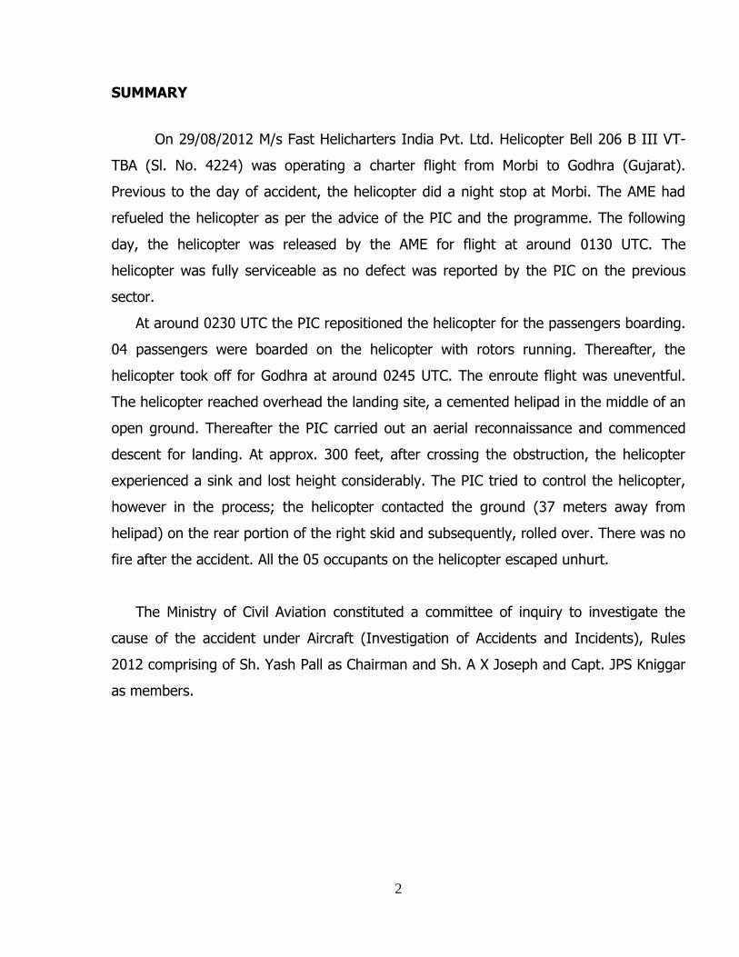
Picture 4 Isolation mount with abraded away material from rotating contact with outer coupling
The spike plate rivets had sheared indicating contact with drag pin / spike during impact
No pre-impact anomalies were observed in the examined components from the
main or tail rotor drive systems and all fractures observed were consistent with overload.
Fuselage Airframe
The helicopter exhibited damage to the nose section consistent with impact loads
applied when the helicopter nosed over.
The pitot tube at the front of the nose section was fractured consistent with
overload forces.
The tail boom reportedly fractured at impact after being impacted by the main
rotor and was at the accident site but was missing and not available for examination
during the wreckage examination in Vadodara. Fractures of forward tail boom surfaces
that were still attached to the aft fuselage were consistent with overload forces from a
main rotor strike.
Much of the landing gear was also missing after recovery of the wreckage (Picture 5).

19
Picture 5 Remnants of landing gear
On the remaining landing gear available for examination, the left skid toe was
observed to have fractured consistent with the nose low impact forces. All seat belts and
shoulders harnesses were intact for the five seat locations and all shoulders harness
inertial reels were found to operate properly by locking when pulled by hand and then
releasing when pressure was relaxed.
There were no pre-impact anomalies in the fuselage airframe and all observed
fractures were consistent with overload forces.
20
Fuel system
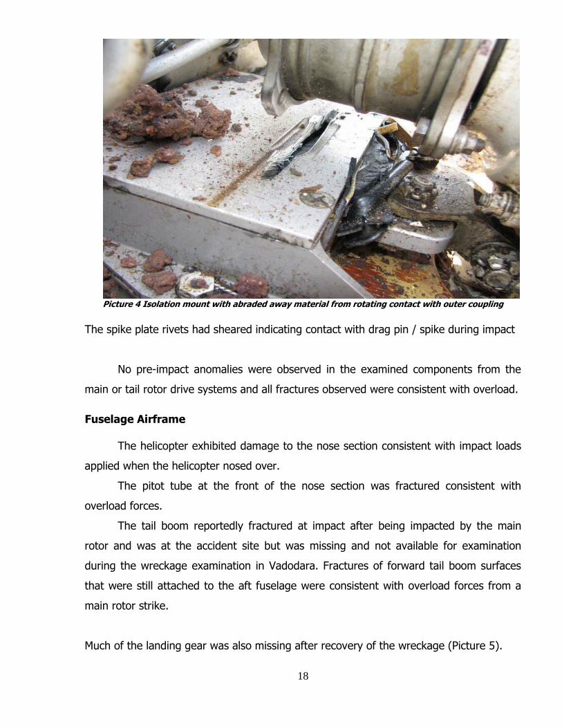
A small amount of clear liquid was observed in the bottom of the fuel tank through
the fuel filler and vapors smelled like fuel. The aft boost pump was observed intact with
the bottom end of the fuel feed line attached (Picture 6).
Picture 6 View through fuel filler of aft boost pump and intact fuel feed line attachment
The top end of the fuel tank feed line was firmly attached to the fitting at the top of the tank.
Fuel lines to the fuel shut-off valve and fuel pressure transducer all appeared
intact with no leakage noted (Picture 7).

21
Picture 7 Fuel lines to shut-off valve and fuel pressure transducer were intact
The fuel valve was removed and observed to be close (Picture 8)
Picture 8 Fuel valve removed from mounting and observed to be in Closed position which
corresponded to the Off position observed on the fuel valve switch in the cockpit (Picture 9).

22
Picture 9 Fuel valve switch in Off position
The pilot reported turning off switches before leaving the helicopter. Some
residual fuel remained in the airframe fuel filter and the IN and OUT fuel fittings were
taped off to preserve the fuel for possible future examination.
No pre-impact anomalies were observed in the fuel system.
Flight Controls
The helicopter was equipped with main rotor flight controls at the pilot position
only (Picture 10).

23
Picture 10 Helicopter equipped with single controls at pilot station
The cyclic and collective sticks were moved by hand and corresponding control
movement was observed to the servo actuators. The left cyclic servo was exercised and
control movement was observed to the swash plate.
The right side servo extension tube aft of the right servo was fractured consistent
with overload bending forces (Picture 11).

24
Picture11. Right servo extension tube fractured consistent with bending overload at impact.
The collective bell crank casting attached to the servo actuator support that
receives input from the vertical tunnel control tube exhibited an overload fracture. The
hydraulic reservoir sight gage exhibited fluid at the bottom of the gage. The pop-out
button on the hydraulic pressure return filter was not extended, indicating that the filter
was not bypassed.
The pitch change links between the swash plate and main rotor hub exhibited
overload fractures consistent with departure of the main rotor at impact. The top end of
both pitch change links were fractured at the clevis insert (Picture 12).

25
Picture 12. Top end of both pitch change links fractured at clevis inserts consistent with overload
The clevises remained attached to their respective pitch change horns. On the bottom
end, one pitch change link was fractured consistent with bending overload forces
approximately 6 inches from the bottom of the link (See Picture13). On the other pitch
change link, the swash plate attachment ear that supports a monoball bearing was
fractured (Picture 13).
Picture13 Pitch change link (red) and swash plate attachment ear (blue) overload fractures

26
consistent with overload forces and the link was not observed. The majority of both pitch
change links were missing and not available for examination.
Since the tailboom and attached tail rotor control system were missing and not
available for examination, it was not possible to fully examine the tail rotor control
system. An overload fracture of the forward end of the long tail rotor control tube that
transits the tailboom was observed at the aft fuselage tailboom attachment fitting
(Picture 14).
Picture14 Overload fracture of long tail rotor control tube near aft fuselage tailboom attach point
This fractured tube was moved by hand and corresponding movement was observed in
the tail rotor controls in the cockpit center pedestal near the tail rotor pedals. The
horizontal control tube that provides continuity between the console and the tail rotor
pedals exhibited fractures consistent with overload at both ends of the tube.

27
The pilot anti-torque pedals were intact (See Picture 15).
Picture15 Pilot anti-torque pedals intact
No pre-impact anomalies were observed in the main or tail rotor flight controls and all
observed fractures were consistent with overload forces. Additionally, the pilot did not
report any controls problems in-flight.
Main Rotor
The main rotor hub assembly was intact except that the pitch horn inputs to the
blade grips were located on the same side consistent with impact forces, where in
normal configuration the pitch horn inputs should be 180 degrees apart from one
another. The mast fractured from hub to mast contact just below the static stop contact
area consistent with ground impact of the main rotor blades.
Both main rotor blades had intact spars. Each plate exhibited chordwise markings
at outboard surfaces consistent with striking the tail booms (Picture 16).

28
Picture16 Main rotor blade tip section with chordwise markings on bottom of blade
Blue paint transfers on leading edge surfaces were consistent the reported colors
of the tailboom (Picture 17).
Picture 17 Blue paint transfers consistent with tailboom color on main rotor blade leading edge

29
One main rotor blade exhibited a downward bend approximately three feet from
the tip consistent with compression forces applied at ground contact when the helicopter
nose over (Picture 18).
Picture 18 Main rotor blade bent down approx. 3 feet from tip consistent with ground contact
The other main rotor blade was removed from the hub at the accident site to
facilitate ground transport. The blade spar had bent forward at the approximate 2/3
span location consistent with inertial forces when the first blade made ground contact
(Picture 19).

30
Picture19 Main rotor blade bent forward consistent with inertial forces when other blade struck round.
No pre-impact anomalies were observed on the main rotor system. The Helicopter completely destroyed as it had sustained substantial and irreparable
damage.

31
1.13 Medical and pathological Information:
Prior to flight the PIC did not undergo any pre-flight medical examination as
required by CAR. Post-accident the PIC was taken to the hospital for medical examination
and no injury was reported. The PIC was also clinically examined for alcohol consumption
and was found satisfactory.
1.14 Fire: There was no fire post-accident.
1.15 Survival aspects:
The accident was survivable. 1.16 Tests and research:
After the accident, preliminary investigation was carried out at the accident site
and subsequently, the helicopter wreckage was transported to Vadodara, Gujarat and
stored at Vadodara Airport for later examination. The manufacturer of Helicopter M/S Bell

32
Helicopter USA and M/S Rolls Royce-USA, the manufacturer of the Engine, associated in
the inquiry.
The Engine along with fuel control unit (FCU) and power turbine governor (PTG)
were sent to the manufacturer for test run and examination of Engine and components.
Video recording, obtained from the news channel, of the last phase of the flight
was forwarded to Bell Helicopters for acoustic analysis.
The relevant portion of the reports submitted by the investigators from Bell
Helicopter, Rolls Royce and Bell helicopter Acoustic lab are incorporated in arriving at
conclusion and finalising the report.
The committee members along with the Representatives from Bell Helicopters
and Rolls Royce Engines visited Vadodara for the inspection of wreckage for
investigation.
The extracts from the Roll-Royce (Indiana polis-USA) report are as below :-
Physical Examination of the Engine:
The physical Examination of the Engine was carried out and the following
observations were made:
Engine Information
Engine Model : Allison 250-C20J
Rating : 420 SHP
Serial Number : CAE-270591
Engine Total Hours : 4571.08 Hours
Engine Last Overhaul : 1239.55 Hours

33
Physical Condition of the Engine
1. Control continuity was established from the collective twist grip to the engine
Controls (including PTG controls) were cycled fully from stop to stop, with no
unusual resistance or excessive travel noted during the control movements.
2. All engine B-nuts and fittings were checked by hand for proper torque and were
found to be satisfactory.
Conditions of B-nuts

34
3. Several pneumatic lines were found to be secured with metal-to-metal mounting
hardware, and there was no evidence of any pneumatic tubing being breached.
4. Both the N1 and N2 Tach-Generator’s wiring was found separated from the Tach-
Generator. The evidence suggests the wiring was pulled from the Tach-Generator
during the accident sequence. The wires exhibited “broom-straw” breakage, which
is consistent with failure in overload.
5. The engine mounts were intact with no apparent deformity. The engine exhibited
no evidence of having been damaged during the crash sequence.
6. During the accident sequence, the engine-to-transmission drive coupling
contacted the striker plate below it. The coupling remained intact, but left
rotational witness marks that penetrated the striker plate.
7. The airframe mounted fuel filter was equipped with a filter bypass and associated
“pop-up” bypass indicator. The bypass had not been activated.
Fuel-Filter ‘Pop-Up’ Bypass Indicator
8. Both N1 and N2 rotors could be rotated by hand. Rotation was smooth and quiet.
Continuity from the power turbine to the power output shaft and tail rotor output
shaft was established.

35
9. The bleed valve was checked by hand for proper operation. The valve operated
smoothly with no lateral play of the poppet valve. Corrosion was noted on the
outer edge of the bleed poppet.
10. The airframe fuel bladder was opened to facilitate the examination of the fuel
system. A small amount of liquid, which smelled of Jet Fuel, remained in the fuel
bladder.
11. The fuel cut-off valve was found in the closed position. The fuel cut-off control in
the cockpit was found in the OFF position. The PIC reportedly pulled the fuel cut-
off prior to exiting the aircraft. The cut-off valves was cycled and functioned
normally. When positioned to the OPEN position, the valve was examined by
boroscope and found to have fully opened.
12. Both the upper and lower Magnetic Chip Detectors (MCDs) were left in-place for
later examination.
13. The N1 and N2 Tach-Generators were removed and a speed handle inserted into
the respective drive gears. Both the N1 and N2 rotated freely by hand. 50 PSI air
was applied to the Pc pneumatic line in order to check the pneumatic system for
leaks.
14. A soap solution was applied to all fittings and connections and lines. No leakage
was detected. The upper and lower MCDs were removed and examined. Both
were found to be free of ferrous debris.
Test Run of Engine at the manufacturers facility in Indianapolis (USA)
The engine was installed on test cell #145 and a 6-point performance test was
conducted to new engine production standards, in accordance with EDR 19034D.
The engine successfully started, ran and shut down. The engine successfully completed
ground-idle, flight-idle, max-continuous-power and take-off power runs, in addition to
“wave-off” max-power increases. When corrected for standard atmospheric conditions,
the engine yielded performance 11.3% below new-production standards at „low cruise‟
(300 horsepower), -9.5% below new-production standards at normal cruise (370
horsepower), and +0.5% above new-production standards at maximum (Take-Off)
power (420 horsepower). The engine then completed “wave-off” max-power transients,

36
simulating the accident sequence, where the power was reduced to flight idle and then
rapidly increased to take-off power. The engine responded normally and responded with
maximum power without surging or hesitation.
Engine Test Run carried out on the Test Bed
Following the successful test cell run, the compressor case halves were opened
and examined. No abnormal wear, erosion or foreign object damage was noted on any
internal compressor components. Evidence of corrosion was present on all compressor
blades.
Condition of Engine’s Compressor Blades

37
Test for Power Turbine Governor (PTG) and Fuel Control Unit (FCU) at the
manufactures facility Honeywell (USA )
The engine controls (Fuel Control Unit (FCU) and Power Turbine Governor (PTG)) were
removed, and sent to their manufacturer (Honeywell, South Bend, Indiana), for Test and
Investigation.
Power Turbine Governor (PTG)
Power Turbine Governor
Physical Condition:
The unit had dirt on the exterior.
The drive shaft was free and moves normally.
The power lever could be moved with slightly more effort than normal.
All pneumatic ports were clear of debris.
FUNCTIONAL TESTING:
The unit was tested using test specification TS11630 “Service Limits”.
Test point 3.010 was recorded as 4485 RPM. The test point limits are 4500 to
4570 RPM. The recorded value is not considered significantly low.

38
All other test points were within limits.
CONCLUSIONS
Functional testing of the unit did not disclose any condition that would cause a
sudden change in output to the fuel control. The Power Turbine Governor functioned
normally.
Fuel Control Unit (FCU)
Fuel Control Unit
Physical Condition:
The unit had dirt on the exterior.
The drive shaft was free and moves normally.
The power lever could be moved with slightly more effort than normal.
All pneumatic ports were clear of debris.
FUNCTIONAL TESTING
The unit was tested using test specification 12862 “Service Limits”.
Test point 3.010 was recorded as 2.5 Pc-Py inches of Hg. The test limits are 0.00
to 0.70 inches of Hg. This test point is affected by allowable field adjustments.
This is the start de-rich adjustment that operates during the start sequence only.

39
Test point 5.010 was recorded as 22.6 PPH. The test limits are 24.0 to 28.0 PPH.
Test point 6.050 was recorded as 208.2 PPH. The test limits are 210.0 to 231.0
PPH
Test point 6.060 was recorded as 247.8 PPH. The test limits are 252.5 to 274.5
PPH.
Test point 7.020 was recorded as 251.5 PPH. The test limits are 279 to 286 PPH.
Test point 9.010 could not be achieved due to the allowable field adjustment.
All other test points were within limits.
Test Result
Functional testing of the unit did not disclose any condition that would cause a sudden
change in fuel flow.
1.17 Organizational and management information:
M/s Fast Helicharters India Pvt. Ltd. is owned by 03 Directors, who run their own
individual businesses apart from the company M/s Fast Helicharters Ltd. PIC involved in
the accident was one of the Directors and also the Accountable Manager of the company.
M/s Fast Helicharters had come into existence in June, 2011 and had a valid Non-
Scheduled Operators Permit issued by DGCA. The company is engaged in day-to-day
Charter Business. The company owned only one Bell 206 B III Helicopter, VT-TBA.
1.18 Additional information: 1.18.1 Video Analysis:
Since the accident flight was a chartered flight with an important public figure,
there was vast media coverage for the arrival of the helicopter. After the accident, the TV
channels were approached and the certified video recording was obtained for analysis. In
the video recording during the approach, it is seen that the helicopter approached with
high rate of descent, lowering of its nose (pitch down), and an increase in the coning of
the main rotor blades is observed. Thereafter a yaw with a bank to the right is seen just
prior to impacting the ground and toppling over.

40
1.18.2 Acoustic Analysis by Bell Helicopter - USA .
During Investigation, the higher fidelity recordings from television news camera
were provided to the Representatives of the Bell Helicopters to carry out the acoustical
analysis of the audio recording.
The aircraft VT-TBA was powered by a Rolls Royce 250-C20J turbine engine, and
had a maximum design gross weight of 3200 lb (1451.5 kg). Characteristic frequencies of
the aircraft were identified through spectrogram analysis of the audio recordings, and
detailed plots of rpm time history for both rotor and engine components were plotted.
The video showing the forward starboard side of the aircraft, covers the final 30
seconds of flight before impact and 76 seconds after impact. The audio data extracted
again provides information on main and tail rotor harmonics, but also provides
information on a gear mesh frequency related to the compressor/gas turbine rpm (N1)
before the crash. In addition, the N1- related gear mesh and the power-turbine torque
meter gear rpm were identified for the full 76 seconds of audio available after impact.
It should be noted that the Bell 206B3 implements a low-rotor-rpm audio alert
which activates when the main rotor rpm decreases to 90% ± 3% (Reference 2). This
audio alert consists of a steady tone. The tone would be heard inside the cockpit, but
would not be audible in any of the available external camera recordings. According to Bell
Flight Safety, the PIC had indicated that he heard the low-rotor-rpm alert during the
descent.

41
Audio Spectrogram Analysis
The audio data from recordings was analysed for frequency content and audio
spectrograms were generated. Various frequency ranges and analysis parameters were
used to identify several of the characteristic frequencies of the Bell 206 B III including
both, the main and tail rotors and their harmonics, engine gearbox gear-mesh
frequencies, and gas generator/compressor speed.
During audio spectrogram analysis the main and tail rotor frequencies and their
harmonics are clearly seen and are identified. The engine gearbox torquemeter gear
mesh frequency, which has a baseline (100%) value of 6000 Hz, is clearly identified.
Analysis of the video shows very similar trends for the main and tail rotor
harmonics prior to the crash, and also supplies some additional information. Audio
spectrograms of the recording presents the first 40 seconds of this data in the lower
frequency range (0 – 600 Hz). The main and tail rotor harmonics are clearly visible
before impact. A 5% increase in frequency of these harmonics is seen early in the
recording and can be attributed to Doppler shift as the aircraft turns and flies toward the

42
camera. Given the geometry and camera location, this frequency shift indicates a ground
speed of 20 – 30 kt at approximately 18 seconds before the crash. Following the crash, a
tone corresponding to the engine gearbox torquemeter rotational frequency is visible
through the end of the recording.
The spectrogram of the video recordings for higher frequency range (7000 –
15000 Hz) indicates a prominent compressor tone, which is coupled to N1, is visible
throughout the recording. Thereafter, complete recording shows a spectrogram at a
lower frequency range (0 – 240 Hz). The torquemeter tone, whose baseline (100%)
value is 167 Hz, is clearly visible.
Analysis Results
The combined trends of the tones identified in the above spectrograms were
transcribed in plots, the time axis corresponds to the elapsed time of the video. The plot
shows the trends for NR, N2 and N1, as a percent of their nominal values, during the first
36 seconds and thereafter shows the remaining time and includes trends for N2 and N1
only, again as a percent of their nominal values.
Skid impact occurs at the video time of 29 seconds. Prior to that, the NR and N2
are at approximately 100%untill about 19 seconds of video time. Then, starting at 19
seconds (10 seconds before impact) both NR and N2 decrease rapidly. The level of
background noise in the audio is too high to determine NR in the final 2 seconds of flight,
so NR is only shown until 27 seconds. However, it is apparent that NR reaches between
65 – 70% before impact. At ground impact, the video shows that the aircraft touches
down on the right skid gear first and rolls to the left. The main rotor then strikes the tail
boom, cutting off the tail rotor and vertical fin. The forward section of the tail boom,
including the horizontal stabilizer, breaks off as a separate piece. The main rotor,
including hub and mast, also detaches from the fuselage.

43
The plot further indicates that approximately 4 seconds before impact, when NR
has dropped to around 80%, N1 is seen to increase sharply, reaching nearly 100% rpm
at the time of ground impact. This steep rise in N1 is consistent with the PIC’s increasing
the throttle prior to impact. After impact N1 quickly falls to around 66%, which closely
corresponds to the compressor nominal ground idle speed of 65%. The increase in N1 is
followed by a brief increase in N2, which then also falls after the crash to around 63%.
The pilot also indicates that the engine continued to run for approximately 65 seconds
following the impact, after which the engine shuts down. During this time following the
crash, N1 stays between approximately 65 – 68%, which corresponds to a power output
of between 20 – 30 shp. A similar trend is seen from N2 which stays at approximately 61
– 63% during this time. At around 94 seconds both N2 and N1 begin to drop. The engine
can be heard in the audio to spin down at this time.
Test Result
It was concluded that during the final 10 seconds of flight, the rotor and engine power
turbine speeds dropped quickly from 100% to approximately 68% at the time of ground
impact. The Bell 206B3 low-rotor-rpm alert is reported to have been heard by the PIC
during descent. A sharp rise in N1 3-4 seconds before skid impact is consistent with a

44
manual throttle increase. After ground impact, the engine compressor returned to ground
idle speed and appeared to keep running for another 76 seconds before shutting down.
Detailed plots are provided showing NR, N2 and N1 time histories for the available
recorded audio data.
1.18.3 Weight & Balance Calculations:
As per the Load & Trim sheet preparation by Pilot – in-Command, the AUW of the
helicopter with 01 pilot & 02 passengers was 1441 kgs. However with 03 passengers the
AUW of the helicopter was 1517 kgs approximately. At the time of take-off the helicopter
was overloaded by approximately 66 kgs and exceeded the maximum internal take-off
weight.
The helicopter operated flight for 01 hour 45 minutes burning157 kgs of fuel
approximately and the landing weight was calculated as 1360 kgs approximately and was
within the limits.
1.19 Useful or effective investigation techniques: NIL 2. ANALYSIS
2.1 Serviceability of the Helicopter:
Bell 206 B III helicopter VT-TBA was manufactured in 1992. The Helicopter VT-TBA
was registered under the ownership of M/s Fast Helicharters India Pvt Ltd., dated
21.06.2011 under category ’A’.
Prior to the accident, the certificate of airworthiness was current and valid up to
07.12.2012. The maximum authorized all up weight is 1451.50 kgs with 01 crew
member. The Helicopter had a valid Aero Mobile Licence and was valid up till 31.12.2013.
This helicopter was operated under Non-scheduled operator’s permit and was valid up to
18.12.2013.

45
This Bell 206 helicopter VT-TBA has logged 4732.09 A/F Hrs, prior to the accident.
The Bell 206 helicopter and its Engine was being maintained as per the maintenance
program consisting of calendar period based maintenance and flying Hours/ Cycles based
maintenance as per maintenance program approved by Regional Airworthiness office,
Mumbai.
Prior to the accident, all major inspections were carried out as per the approved
maintenance programme. Subsequently all lower inspections, after last flight inspection
and pre-flight checks were carried out as and when due before the accident.
All the concerned Airworthiness Directive, Service Bulletins, DGCA Mandatory
Modifications on this helicopter and its engine have been complied with as & when due.
The status of all Airworthiness Directives as issued by DGCA through mandatory
modifications for Helicopter including Main Rotor blades were also checked and found
satisfactory.
Prior to accident flight there was no pending/repetitive defect entered on the Pilot
Defect Report/Technical Logbook of the helicopter. The Certificate Release to Service
was valid prior to the accident flight. Examination of the wreckage site also revealed that
there was no in-flight disintegration of the helicopter parts. The parts had disintegrated
only after the impact with the ground.
In view of the above, it is inferred that the serviceability of the helicopter is not a
factor to the accident.
2.2 Weather:
Since, the helipad at Morbi and Godhra were temporary helipad, no MET services
were available. The weather at the time of departure from Morbi was co-ordinated by
PIC with ATC, Rajkot and was reported to be fine with fair visibility. The enroute weather
was fine. The weather at Godhra was co-ordinated with ATC, Vadodara and the weather
was reported to be fine with fair visibility.

46
2.3 Pilot handling of the helicopter:
The helicopter VT-TBA had arrived at Morbi helipad on 27.08.2012 and was
scheduled for a flight on 29.08.2012. The helicopter departed from Morbi to Godhra at
around 0800 UTC. The flight was planned with 03 passengers, however, 04 passengers
boarded at Morbi for the flight. A load and trim sheet based on the planned flight had
been prepared catering for 01 pilot, 03 passengers with 75 (284 ltrs) gallons of fuel. As
per the calculations at the time of take-off the helicopter was overloaded by
approximately 66 kgs and exceeded the maximum internal take-off weight. However the
helicopter operated flight for 01 hour 45 minutes, burning 157 kgs of fuel approximately
and the landing weight was calculated as 1360 kgs approximately, which was within the
limits. The helicopter though being overloaded for the flight from Morbi, the PIC initiated
the flight without assessing the effect on performance of the helicopter with an additional
passenger. The flight from Morbi to Godhra was uneventful.
On reaching overhead Godhra, the PIC made a large circle to identify the landing
site, assess the helipad (concrete), obstructions around the helipad, winds and being
satisfied, decided upon the approach direction before commencing the descent.
In the video recording, during the approach, the helicopter rate of descent is seem
to increase following by lowering of its nose (pitch down), an increase in coning of the
rotor blades and a yaw with a bank to the right just prior to impacting the ground and
toppling over. It is observed that helicopter crossed the high-tension cables with
sufficient clearance, thereafter, the helicopter appeared to experience a sink and
subsequent pitch down. In the final stages, before touch-down, the helicopter is seen
yawing and banking to the right and the right rear skid contacting the ground, followed
by it toppling over.
The PIC after crossing the high-tension wires with sufficient clearance, continued
the approach. After crossing the obstruction, the PIC experienced a sink which he
realized that the approach was undershooting and that the helicopter would arrive short
of the helipad. Though the PIC mentioned that the Main Rotor and engine indicator

47
showing 97% rpm, the helicopter experienced a sink after crossing the wires. To arrest
the sink, he came up on collective and noticed that the main rotor and engine rpm
indicator decreased and stabilized between 97% and 90 % and the approach becoming
undershooting which he deliberately did not correct. Subsequently he lowered the
collective to regain the rpm. The PIC assessing the situation to be one of a governor
failure (engine under speeding), he decided to carry out a no hover landing with forward
speed. At this point the main rotor/engine rpm had not reached the minimum limit of 90
%, at which the low rotor rpm audio warning would have sounded.
Close to the ground approximately 25 feet AGL, the PIC started applying the
collective to arrest the rate of descent and to reduce the forward speed. On application
of collective, the rotor rpm dropped below 90 % and the low rotor rpm audio warning
horn sounded. On hearing this, the PIC rapidly applied full collective and the throttle
opened to almost full on as evident from the acoustic analysis, that 3 to 4 seconds prior
to impact, the throttle was manually increased to full power. Although N1 increased
significantly in 3 to 4 seconds prior to impact from an apparent increase in throttle to full
on, there was not enough time for N2 and NR recovery prior to impact. This action caused
the helicopter to yaw and bank to the right which he did not correct/control and the
helicopter impacted the ground on the right rear skid while still moving forward.
Subsequently the left skid contacted the ground and dug in to the soft ground arresting
its forward speed but its forward momentum caused the helicopter to topple over.
Even though the PIC had wrongly assumed/identified the decrease in the main
rotor/engine rpm as a case of governor failure (engine under speeding), he should have
executed an autorotative landing with the power available and with positive zero forward
speed.
During investigation, the engines along with its components (Fuel Control Unit,
Power Turbine Governor) were strip examined / test run and were found satisfactory. As
per the report, all the components and engine were serviceable prior to the accident.

48
From the foregoing, it is evident that the handling of the Flight/Engine Controls by
the PIC is a primary factor to the accident.
2.4 Circumstances leading to the accident:
The flight from Morbi to Godhra was planned for 03 passengers, however 04
passengers boarded the helicopter from Morbi. The PIC initiated the flight without
assessing the effect on performance of the helicopter with an additional passenger. The
flight from Morbi to Godhra was uneventful. Prior to the accident flight, the flight was
planned with 03 passengers, however, it took off with 04 passenger. The helicopter was
overloaded prior to its departure from Morbi. After flying for 1 hour 45 minutes, the
helicopter was within the landing weight limits.
In the reconnaissance of the area around the helipad at Godhra, the PIC did not
notice puddles of water at many places around the designated concrete helipad. As it
had rained the previous day, the ground was soft.
After crossing the high-tension wires, the helicopter experienced a sink and
subsequently he lowered the collective to regain the rpm. To arrest the sink, he came up
on collective and noticed that the main rotor and engine rpm had decreased. This was
probably due to a variation in the throttle position as evident from the acoustic analysis.
The PIC realized that the approach was undershooting and that the helicopter
would arrive short of the helipad. Landing on such ground should have been avoided,
especially with forward speed, as it could result in the helicopter skids getting bogged
down in the soft ground and cause the helicopter to nose over. Landing on such soft
ground should have been with ‘zero’ forward speed, however the PIC chose to land with
forward speed.
At approximately 25 feet above the ground, on applying the collective and hearing
the low rotor RPM audio horn, the PIC opened the throttle (evident from the acoustic
analysis) and came up on full collective. Lack of coordination of controls in the final

49
moments of the flight, wherein the helicopter was permitted to yaw and bank to the right
while touching down with forward speed resulted into the accident.
3. CONCLUSIONS:
3.1 Findings:
a) The Certificate of Airworthiness and the Certificate of Registration of the helicopter
was valid on the date of accident.
b) The certificate release to service (CRS) was valid at the time of accident.
c) The PIC was holding a valid license on the type of helicopter.
d) The PIC had not undergone the simulator recurrent training as required by CAR.
All the other ancillary trainings were valid.
e) The flight from Morbi to Godhra was planned for 03 passengers, however, 04
passengers boarded the helicopter. The helicopter took – off for flight without
making any corrections/changes in the Load & Trim Sheet to cater for the
additional passenger for power and CG variations.
f) During the aerial reconnaissance overhead Godhra, the PIC did not notice the
puddles of water and appreciate that the area around the helipad was soft
ground.
g) After crossing the high-tension wires, the helicopter experienced a sink and the
PIC realized that the approach was undershooting and that the helicopter would
arrive short of the helipad.
h) To arrest the sink, the PIC came up on collective, and observed that the main
rotor and engine rpm indication had decreased. Subsequently he lowered the
collective to regain the rpm.
i) The PIC wrongly assessing the situation to be one of a governor failure, decided
to carry out a no hover landing with forward speed.
j) At approximately 25 feet AGL, the PIC applied collective to arrest the rate of
descent and to reduce the forward speed. The rotor rpm dropped below 90 % and
the low rotor rpm audio warning horn sounded.

50
k) The PIC rapidly applied full collective and opened the throttle to almost full power.
This action caused the helicopter to yaw and bank to the right which he did not
correct/control and the helicopter impacted the ground.
l) The engine, along with its components (Fuel Control Unit and Power Turbine
Governor), was sent to the manufacturer’s facility for strip examination and test
run. All the units were found satisfactory.
m) The weather was not a factor to the accident.
3.2 Probable cause of the Accident:
The rapid and large collective movements in the final stage with inadequate left
rudder application resulted in the helicopter yawing and banking to the right. These
actions eventually resulted into the accident.
Following were the contributory factor:
The reduction in the throttle setting after crossing the wire obstruction on the
approach, most probably resulted in setting off a sequence of events leading to
the drop in Engine and Main Rotor RPM and causing the PIC to assess the
situation as one of governor failure (Engine underspeed).
Mishandling of the controls in the final moments of the approach, just prior to
the landing.
Incorrect procedure/technique adopted for landing on soft ground.

51

52
AAIB Aircraft Accident Investigation Bureau,India
AGL Above Ground Level
A/F Airframe Hours
AOA Angle of Attack
AMSL Above Mean Sea Level
AME Aircraft Maintenance Engineer
ARC Airworthiness Review Certificate
ASB Alert Service Bulletin
ATC Air Traffic Control
AUW All Up Weight
C of A Certificate of Airworthiness
CAR Civil Aviation Requirements
CEB Commercial Engine Bulletin
CSL Commercial Service Letter
CG Centre of Gravity
CPL(H) Commercial Pilot License (Helicopter)
CP Collective Pitch
CRM Crew Resource Management
CVR Cockpit Voice Recorder
CSL Commercial Service Letter
CT Compressor-to-Turbine Coupling
DAW Director of Airworthiness
DDG Deputy Director General
DGCA Directorate General of Civil Aviation
DGR Dangerous Goods Regulations
DFDR Digital Flight Data Recorder
FAA Federal Aviation Administrartion
FCU Fuel Control Unit (Engine )
FRTOL Flight Radio Telephone Operator’s License
FSN Fuel Spray Nozzle
ISRO Indian Space Research Organization
LH Left Hand
L & T Load & Trim
MCD Magnetic Chip Detector
NDT Non Destructive Testing
NSOP Non-Scheduled Operating Permit
NTSB National Transportation Safety Board, USA
N1 Gas Generator rpm
NR Rotor rpm

53
N2 Power Turbine rpm
PIC Pilot In Command
Pax. Passenger
PTG Power Turbine Governor
RH Right Hand
rpm Revolution per minute
RT Radio Telephony
RTR (C) Radio Telephony Restricted
SOP Standard Operating Procedures
SHP Shaft Horse Power
Vdc Volts (Direct Current )
VHF Very High Frequency
UTC Co-ordinated Universal Time


![[PPT]PowerPoint Presentation - International Helicopter … · Web viewUS Civil Helicopter Emergency Medical Services Accident Analysis Federal Aviation Administration Presentation](https://static.fdocuments.in/doc/165x107/5b0cce6c7f8b9a952f8c9558/pptpowerpoint-presentation-international-helicopter-viewus-civil-helicopter.jpg)