REPORT OF GEOTECHNICAL EVALUATION - Maine.gov · recommendations in the following report are based...
30
REPORT OF GEOTECHNICAL EVALUATION Report of Geotechnical Evaluation Proposed Maine Dept. I.F.&W. Casco Hatchery Site Improvements Fish Hatchery Road, Casco, Maine For Maine Department of Inland Fisheries & Wildlife 41 State House Station Augusta, Maine 04333-0041 Prepared by MAIN-LAND DEVELOPMENT CONSULTANTS, INC. Livermore Falls, Maine November 04, 2016
Transcript of REPORT OF GEOTECHNICAL EVALUATION - Maine.gov · recommendations in the following report are based...

REPORT
OF
GEOTECHNICAL EVALUATION
Report of Geotechnical Evaluation
Proposed Maine Dept. I.F.&W. Casco Hatchery Site Improvements
Fish Hatchery Road, Casco, Maine
For
Maine Department of Inland Fisheries & Wildlife
41 State House Station
Augusta, Maine 04333-0041
Prepared by
MAIN-LAND DEVELOPMENT CONSULTANTS, INC.
Livermore Falls, Maine
November 04, 2016

TABLE OF CONTENTS
Page Number
1 Proposed Construction
1 Subsurface Exploration
2 Laboratory Testing
2 Subsurface Conditions
2 Evaluation
3 Building Foundations
3 Construction Considerations
3 New Pipe Trench
3 Recommendations
4 Site Excavation and Subgrade Preparation
5 Building Foundations
6 Cast-in-Place Concrete Retaining and Foundation
Walls
6 Foundation Drainage
7 Closure
Attachments:
Figure 1, Existing Conditions Survey, with revised Boring locations
Appendix A. Main-Land Exploration Logs
Appendix B. Laboratory Test Results

MAIN-LAND helps people add value to their land: to understand it, develop it, and protect it.
November 04, 2016
Maine Department of Inland Fisheries & Wildlife
41 State House Station
Augusta, Maine 04333-0041
Attention: Mr. Todd Langevin, Superintendent of Hatcheries
Subject: Report of Geotechnical Evaluation
Proposed Maine Dept. I.F.&W. Casco Hatchery Site Improvements
Fish Hatchery Road, Casco, Maine
Dear Todd:
Main-Land Development Consultants, Inc. (Main-Land) is pleased to present the following report of
geotechnical evaluation for the subject project in Casco, Maine. The following report provides geotechnical
recommendations for final design and construction of the proposed new water treatment building, as well as
subsurface information along the planned upgraded water supply pipeline route. The geotechnical
recommendations in the following report are based on recent soil test borings conducted to characterize
subsurface conditions in and near the proposed improvement footprints.
PROPOSED CONSTRUCTION
Existing layout and grading at the Inland Fisheries & Wildlife (IF&W) Hatchery in Casco, Maine are
depicted on Figure 1, Existing Conditions Survey, with revised boring locations, attached (Note: this
drawing was provided by Owen Haskell Inc., Project Surveyors). The proposed new water treatment
building will be located in the vicinity of the existing UV building.
SUBSURFACE EXPLORATION
The subsurface exploration program for the proposed site improvements was performed by Main-
Land during August 12, 2016 and consisted of six test borings designated TB-1 through TB-6. Exploration
locations were selected by HDR, Inc. (Project Design Engineer) and staked in the field by Owen Haskell
Inc. See Figure 1, attached, for the as-drilled locations of the subsurface explorations. All borings except
TB-2 and TB-5 were drilled at the staked locations. The following table provides the offsets with respect to
the project coordinate system of borings TB-2 and TB-5:
Boring No. Offset North Offset East Offset
vertical
New
Northing
New Easting New
Vertical
TB-2 -5.523’ 2.344’ +1.75’ 428987.690 2858157.252 405.86’
TB-5 -17.025’ -33.413’ -2.81’ 428820.316 2858389.772 424.22’
Report of Geotechnical Evaluation
Proposed Maine Dept. I.F.&W. Casco Hatchery Site Improvements
Fish Hatchery Road, Casco, Maine
MAIN-LAND DEVELOPMENT CONSULTANTS, INC 2 of 7
www.main-landddci.com
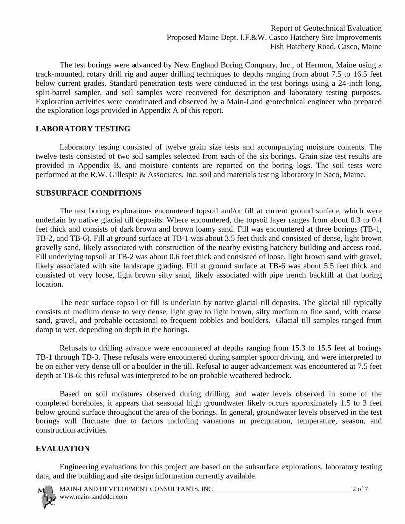
The test borings were advanced by New England Boring Company, Inc., of Hermon, Maine using a
track-mounted, rotary drill rig and auger drilling techniques to depths ranging from about 7.5 to 16.5 feet
below current grades. Standard penetration tests were conducted in the test borings using a 24-inch long,
split-barrel sampler, and soil samples were recovered for description and laboratory testing purposes.
Exploration activities were coordinated and observed by a Main-Land geotechnical engineer who prepared
the exploration logs provided in Appendix A of this report.
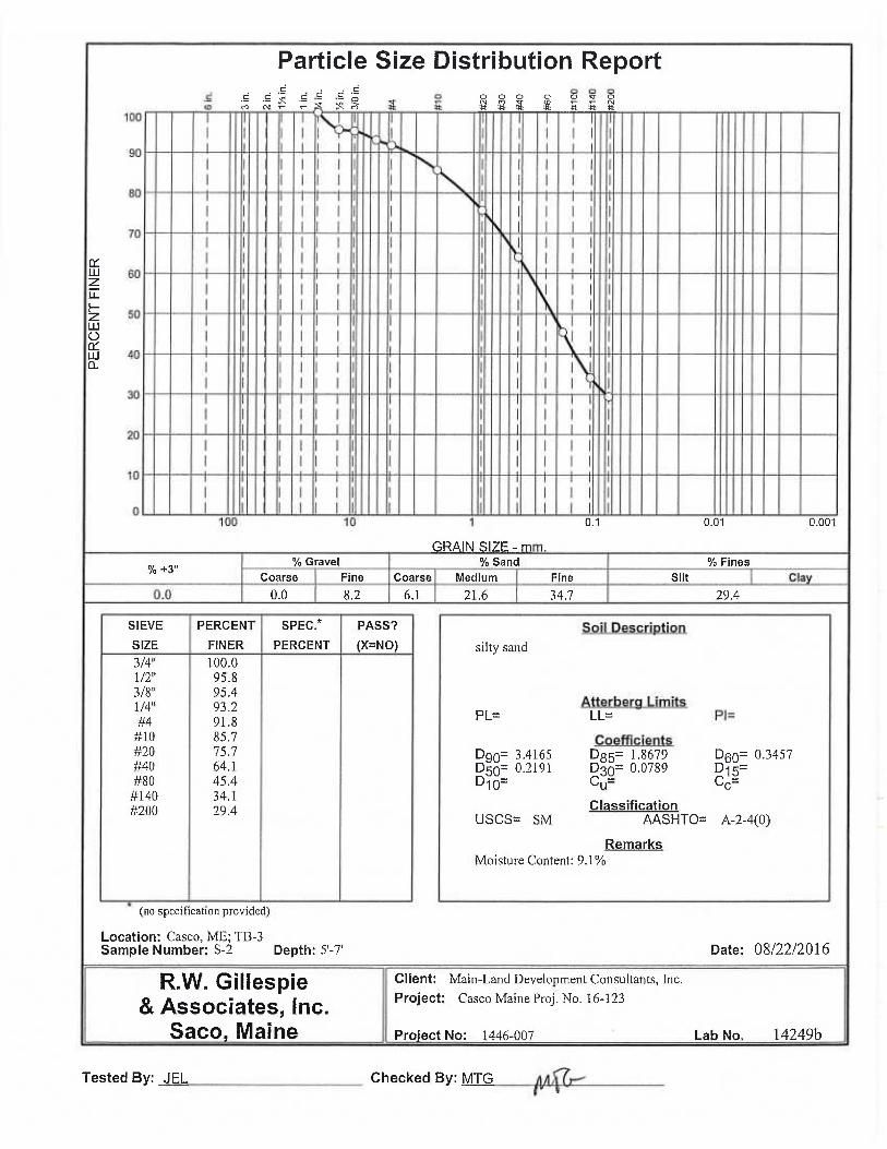
LABORATORY TESTING
Laboratory testing consisted of twelve grain size tests and accompanying moisture contents. The
twelve tests consisted of two soil samples selected from each of the six borings. Grain size test results are
provided in Appendix B, and moisture contents are reported on the boring logs. The soil tests were
performed at the R.W. Gillespie & Associates, Inc. soil and materials testing laboratory in Saco, Maine.
SUBSURFACE CONDITIONS
The test boring explorations encountered topsoil and/or fill at current ground surface, which were
underlain by native glacial till deposits. Where encountered, the topsoil layer ranges from about 0.3 to 0.4
feet thick and consists of dark brown and brown loamy sand. Fill was encountered at three borings (TB-1,
TB-2, and TB-6). Fill at ground surface at TB-1 was about 3.5 feet thick and consisted of dense, light brown
gravelly sand, likely associated with construction of the nearby existing hatchery building and access road.
Fill underlying topsoil at TB-2 was about 0.6 feet thick and consisted of loose, light brown sand with gravel,
likely associated with site landscape grading. Fill at ground surface at TB-6 was about 5.5 feet thick and
consisted of very loose, light brown silty sand, likely associated with pipe trench backfill at that boring
location.
The near surface topsoil or fill is underlain by native glacial till deposits. The glacial till typically
consists of medium dense to very dense, light gray to light brown, silty medium to fine sand, with coarse
sand, gravel, and probable occasional to frequent cobbles and boulders. Glacial till samples ranged from
damp to wet, depending on depth in the borings.
Refusals to drilling advance were encountered at depths ranging from 15.3 to 15.5 feet at borings
TB-1 through TB-3. These refusals were encountered during sampler spoon driving, and were interpreted to
be on either very dense till or a boulder in the till. Refusal to auger advancement was encountered at 7.5 feet
depth at TB-6; this refusal was interpreted to be on probable weathered bedrock.
Based on soil moistures observed during drilling, and water levels observed in some of the
completed boreholes, it appears that seasonal high groundwater likely occurs approximately 1.5 to 3 feet
below ground surface throughout the area of the borings. In general, groundwater levels observed in the test
borings will fluctuate due to factors including variations in precipitation, temperature, season, and
construction activities.
EVALUATION
Engineering evaluations for this project are based on the subsurface explorations, laboratory testing
data, and the building and site design information currently available.

Report of Geotechnical Evaluation
Proposed Maine Dept. I.F.&W. Casco Hatchery Site Improvements
Fish Hatchery Road, Casco, Maine
MAIN-LAND DEVELOPMENT CONSULTANTS, INC 3 of 7
www.main-landddci.com
Building Foundations
Information provided by HDR, Inc., Project Design Engineer, indicates that new treatment
building wall loads will not exceed 2,000 lbs. per foot of wall and the headtank bearing pressure will be no
greater than 1,000 lbs. per square foot. Total and differential settlements should not exceed 1” and ½”,
respectively.
Construction Considerations
Exposed subgrade within the building area will be susceptible to disturbance from moisture or foot
traffic during construction, especially where subgrade consists of silty glacial till soils. All spread footing
foundations and floor slab areas should be underlain by a minimum of 8” thick pad of compacted,
geotextile-reinforced structural fill to better distribute footing and floor loads, protect subgrade from
disturbance, and act as a working surface for subsequent foundation construction activities.
It is anticipated that permanent groundwater levels will occur near or above footing excavations. In
addition, surface water runoff that penetrates the upper fill and loose till soils could perch at the underlying
interface with less permeable till. This shallow groundwater and/or infiltrated surface water could infiltrate
foundation excavations and require open pumping during construction to avoid subgrade disturbance and
allow construction in-the-dry.
New Pipe Trench
It is anticipated that the new water supply pipe will be placed in or near the existing pipe trench
which extends from the existing dam to the Fish Hatchery. The existing pipe will likely be removed from
the trench prior to placing the new pipe, and new backfill will be placed around the new pipe. Design
freezing temperature penetration depth through granular trench backfill is anticipated to be on the order of 5
to 6 feet below bare ground surface. Pipes which are not below this anticipated freezing penetration depth
could be further protected using a minimum of 2” of rigid styrofoam insulation over the pipe.
Probable bedrock was encountered near 7.5 feet depth in boring TB-6, and several apparent boulders
were also encountered at that boring location. As the existing pipe trench approaches the dam, it is likely
that bedrock becomes shallower. During construction, bedrock might be present at or above proposed new
pipe trench invert. The bedrock consists of relatively hard, slightly weathered granite. If necessary, it is
anticipated that small volumes of bedrock could be excavated using a mechanical hoe ram. Controlled
blasting may be necessary to remove larger amounts of bedrock, depending on final trench elevations.
RECOMMENDATIONS
The following recommendations are provided for design of building foundations. It is recommended
that foundation design and construction be in compliance with building code requirements and applicable
ordinances, regulations, and rules, including International Building Code 2012 (IBC 2012) and ASCE 7-10
for seismic site classification.

Report of Geotechnical Evaluation
Proposed Maine Dept. I.F.&W. Casco Hatchery Site Improvements
Fish Hatchery Road, Casco, Maine
MAIN-LAND DEVELOPMENT CONSULTANTS, INC 4 of 7
www.main-landddci.com
Site Excavation and Subgrade Preparation
Prior to placing new fill inside the new building footprint, all unsuitable materials including topsoil,
organics, obsolete structural elements such as asphalt drives and underground utilities, and loose fill, should
be removed. Existing underground utilities might have to be relocated; discontinued utilities should be
removed in their entirety from beneath new foundations and structural elements. Subgrade beneath new
floor slab areas which consists of existing granular fill should be proofrolled with the largest practical
compaction equipment to re-densify soils disturbed during clearing and to identify subgrade soils which
weave beneath the proofroll and are not suitable to support subsequent fill and floor slab placement. All
existing fill should be removed from beneath spread footing foundations, down to native glacial till soils.
Following clearing and removal of unsuitable subgrade, all suitable subgrade beneath floor slab and
footings should be covered with the recommended minimum 8” thick pad of compacted, geotextile-
reinforced structural fill. The geotextile should consist of a woven geotextile stabilization fabric (Mirafi
600X or equivalent) to act as a separator and reinforcement for overlying compacted structural fill. The
geotextile should be placed on suitable subgrade and overlapped a minimum of 12 inches at its edges.
Compacted structural fill should be placed over the geotextile and up to design base of floor slab and
base of spread footing foundations (Note: If the Structural Engineer prefers a layer of compacted crushed
stone underlying floor slab, then the stone thickness should be in addition to the minimum recommended
structural fill pad thickness). In addition, structural fill should be used as compacted backfill in all
foundation excavations. Structural fill should meet the following gradation:
Sieve Size or Screen Number Percent Passing
3 inch 100
¼ inch 25 to 70
No. 40 0 to 30
No. 200 0 to 7
(Note: this Structural Fill is similar to MEDOT 703.06 Aggregate Subbase Type D, except that it is
3-inch minus, and might be produced by passing Type D over a 3-inch sieve)
Based on the grain size results from test boring soil samples, on site soils will not meet the above
recommended structural fill gradation, and are therefore not suitable for reuse as structural fill. On site soils
will likely not meet the gradation of select pipe backfill. On site soils, particularly those excavated during
new pipe installation, will likely be suitable for reuse above the select pipe backfill zone in the remainder of
the utility trench, except in areas where utility trenches pass beneath structural elements such as foundations
or access roads. Because of the anticipated variability of excavated on site soils, it might be difficult to
achieve recommended compaction where these soils are reused as general utility trench backfill.
Minimum compaction requirements with reference to modified proctor density (ASTM D 1557) for
all fill materials are as follows: 95 percent beneath building and driveway areas, and immediately
surrounding and minimum 12” above buried pipe; 92 percent compaction in walkways and utility trenches
above the 95 percent compaction zone; and, 90 percent compaction beneath lawns or unimproved areas.
Compaction should be performed by complete coverages on each lift such that the required density
is achieved throughout each lift. One coverage consists of a forward pass and a back pass (2 passes). In open

Report of Geotechnical Evaluation
Proposed Maine Dept. I.F.&W. Casco Hatchery Site Improvements
Fish Hatchery Road, Casco, Maine
MAIN-LAND DEVELOPMENT CONSULTANTS, INC 5 of 7
www.main-landddci.com
areas, a minimum of two coverages in each of two directions perpendicular to each other should be made to
compact each lift, with a maximum loose lift thickness of 12 inches. In confined areas such as foundation
backfill zones adjacent to foundation walls and near existing structures, smaller compaction equipment such
as light vibratory drum roller or hand-operated plate compactor should be used with maximum loose lift
thickness reduced to 6 inches.
In-place density tests should be performed on each lift of compacted fill at the following minimum
testing frequencies: one test per 1,000 square feet beneath buildings, parking and access areas, and
walkways; one test per 1,000 square feet beneath lawns or unimproved areas; one test per 30 lineal feet in
continuous footing trenches; 2 tests in isolated column footing structural fill pads; and, one test per 75 lineal
feet in utility trenches.
During construction, compacted fill which becomes wet and/or disturbed should either be allowed to
dry in place and be re-compacted, or be removed and replaced with compacted structural fill prior to placing
additional fill over the disturbed area.
Building Foundations
It is anticipated that the new building can be supported on conventional spread footing and slab-on-
grade foundations. It is recommended that foundations be supported by a minimum 8” thick layer of
compacted, geotextile-reinforced structural fill.
The 8” thick reinforced structural fill pad should extend a minimum 12” beyond the outside edge of
footings, and be compacted to a minimum of 95 percent of modified proctor density. A layer of woven
geotextile stabilization fabric (Mirafi 600X or equivalent) should be placed to cover suitable subgrade
beneath the entire structural fill pad. Excavation for structural fill pads should be made using a smooth-
edged bucket to minimize subgrade disturbance and to provide a uniform surface for geotextile placement.
The proposed building should be designed to withstand lateral, uplift, and overturning forces due to
earthquake. Soils encountered in the explorations are not considered susceptible to liquefaction. In
accordance with IBC 2012 and ASCE 7-10, the soil profile at the site is classified as Site Class C.
Footings should be designed for a maximum bearing pressure of 2,500 pounds per square foot (psf).
Anticipated total settlements are on the order of 1/2 inch or less, and differential settlements are anticipated
to be less than about 1/4 inch. Continuous wall footings should be at least 2.5 feet wide and isolated footings
should be at least 3 feet wide.
For frost protection, all exterior footings and interior footings in unheated areas should be a
minimum of 4.5 feet below lowest adjacent ground surface. Interior footings in heated areas should bear a
minimum of 18 inches below top of ground floor slab. All footings and floor slab elements should be
protected from freezing and frost action during construction.
Interior floors may be slab-on-grade supported on the minimum 8” thick layer of compacted,
geotextile-reinforced structural fill. Additional subslab fill required by the Project Structural Engineer, such
as a leveling layer of crushed stone, should extend above the 8” thick structural fill pad. A subgrade
modulus of 150 pounds per cubic inch should be used for slab-on-grade design. It is anticipated that

Report of Geotechnical Evaluation
Proposed Maine Dept. I.F.&W. Casco Hatchery Site Improvements
Fish Hatchery Road, Casco, Maine
MAIN-LAND DEVELOPMENT CONSULTANTS, INC 6 of 7
www.main-landddci.com
additional slab-on-grade construction details including vapor retarder type and thickness, concrete thickness
and reinforcing, and control joint depth and spacing will be provided by the Project Structural Engineer.
Exterior slabs at entrances and loading docks should be underlain by a minimum of 2 feet of free-draining
material such as compacted structural fill and/or crushed stone wrapped in filter fabric, and the surrounding
areas should be sloped away from the structure to reduce available moisture for frost lens and ice
generation.
Lateral loads from wind and earthquake may be resisted by friction between the footing bottoms and
subgrades and earth pressures against sides of footings and exterior walls. A friction coefficient of 0.35 is
recommended for footings bearing on compacted structural fill; a lateral bearing of 200 pound per square
foot per foot depth is recommended. Only compacted structural fill should be used as backfill of footings,
piers, and foundation walls.
Cast-in-Place Concrete Retaining and Foundation Walls
Retaining walls for loading docks, and tank and foundation walls with unbalanced loading, should be
designed to resist lateral earth pressures. For walls that are not restrained against rotation (active condition)
an equivalent fluid unit weight of 45 pounds per cubic foot (Ka = 0.33) should be used. Lateral pressure due
to surcharge behind the wall should be considered in addition to the earth pressure and calculated as the
surcharge pressure multiplied by the active pressure coefficient of 0.33 and applied as a uniform lateral
pressure distribution at the back of the wall.
Walls fixed against rotation should be designed to resist at-rest equivalent fluid unit weight of 65
pounds per cubic foot (Ko = 0.5). Lateral pressure due to surcharge should be considered in addition to the
earth pressure and calculated as the surcharge pressure multiplied by the active pressure coefficient of 0.5
and applied as a uniform lateral pressure distribution at the back of the wall. The above active and at-rest
equivalent fluid unit weights assume that foundation walls are fully drained.
Foundation Drainage
Foundation drains should be installed at the base of exterior footings and be discharged via gravity to
the site storm drainage system. We recommend that foundation drains be installed both on the inside and
outside of the exterior footings; the “interior” footing drains will help to provide subgrade drainage during
construction when the building footprint is open to precipitation. A connecting pipe may need to be cast
through the foundation to allow the “interior” footing drains to discharge. Roof drains should not be
connected to the foundation drains. The foundation drains should consist of 4-inch diameter perforated PVC
pipe surrounded by a 6-inch thick layer of ¾ inch crushed stone completely wrapped in a non-woven filter
fabric such as Mirafi 140N or equivalent.
Main-Land recommends that design groundwater elevation be taken as 2 feet below pre-construction
ground surface in building areas. The bases of water treatment tanks inside the building which are lower
than this elevation should be considered susceptible to hydrostatic uplift due to seasonal high groundwater,
especially when a tank is empty. The tanks should resist uplift to the design elevation by weight and/or
restraint. In addition, if gravity flow allows, drainage could be provided beneath the tank by placing a 12-
inch thick layer of geotextile-wrapped, ¾ inch crushed stone beneath the tank bottom, and sloping subgrade
toward the center of the tank where a 4-inch diameter perforated PVC pipe would be placed at the base of

Report of Geotechnical Evaluation
Proposed Maine Dept. I.F.&W. Casco Hatchery Site Improvements
Fish Hatchery Road, Casco, Maine
MAIN-LAND DEVELOPMENT CONSULTANTS, INC 7 of 7
www.main-landddci.com
the stone layer. The geotextile fabric (Mirafi 140N or equivalent) would separate the crushed stone from
surrounding soils to prevent the infiltration of fines to the stone, and would not have to extend beneath the
tank itself.
CLOSURE
The analyses and recommendations provided in this report are based in part upon the data obtained
from widely spaced explorations. The nature and extent of variations between these explorations may not
become evident until construction. If variations are encountered, it will be necessary to re-evaluate the
recommendations of this report. To the best of Main-Land’s knowledge, this report of geotechnical
evaluation has been prepared in accordance with generally accepted soil and foundation engineering
practices. No other warranty, expressed or implied, is made.
Main-Land looks forward to providing continuing engineering, design, and construction observation
services for future phases of the project.
Sincerely,
Main-Land Development Consultants, Inc.
__________________________________
Scott R. Dixon, P.E., C.G., L.S.E.
Senior GeoEngineer


Report of Geotechnical Evaluation
Proposed Maine Dept. I.F.&W. Casco Hatchery Site Improvements
Fish Hatchery Road, Casco, Maine
MAIN-LAND DEVELOPMENT CONSULTANTS, INC
www.main-landdevelopment.com
APPENDIX A
Main-Land Exploration Logs

TB-1
PAGE: 1 of 1
S. Dixon, P.E., C.G., L.S.E.
DEPTH: 15.4'
augers
0 S1 0 10
24/16 21 35 Dense, light brown gravelly Sand, trace silt, dry to damp G.S.
14 to dry MC = 3.5%
2 14 -FILL-
3.5'
5 S2 5 24/24 27 Dense, light gray, with mottling near 5.5', silty Sand, little fine gravel,
24 45 damp grading to moist near 6.5', with probable cobbles and G.S.
21 small boulders MC = 7.9%
7 18
10 S3 10 24/24 17 Dense, same as above, wet
20 40
20
12 28
-GLACIAL TILL DEPOSITS-
15 S4 15 5/5 55/0.4' 55+ Same as above, except moist
15.4Bottom of Exploration at 15.4'; Spoon sampler refusal on probable
boulder at 15.4'
20
REMARKS: TB-1 drilled at surveyed location
PROJECT: IFW Hatchery Improvements LOG OF SUBSURFACE
EXPLORATION
EXPLORATION NO.
LOCATION: Casco, Maine
JOB NO. 16-123 DRILLER / RIG: New England Boring Co., Hermon, ME/ATV Rig
LOGGED BY: DRILLING METHOD: 2-1/4" I.D. Hollow Stem Augers
EXP. START: 12-Aug-16 DRILL STEM OD: 6"
EXP. COMP: 12-Aug-16 HAMMER TYPE: Safety Hammer
EXISTING GRADE: El. 400.8' +/- WEIGHT & FALL: 140 lb./30"
EXP. LOCATION: See Exploration Location Plan GROUNDWATER OBS: Water at 6.7' in open hole after pull
LAB.REC"
DE
PT
H
SA
MP
LE
NO
.
RA
NG
E
PEN"H
AM
ME
R
BL
OW
SN DESCRIPTION

TB-2
PAGE: 1 of 1
S. Dixon, P.E., C.G., L.S.E.
DEPTH: 15.3'
augers
0 S1 0 1 Brown loamy Sand, dry -TOPSOIL-
24/18 6 10 0.4' Loose, light brown Sand, little gravel, dry G.S.
4 1.0' -FILL- MC = 7.0%
2 10 Loose to medium dense light yellow brown mottled to 1.5', light gray
below 1.5', silty Sand, little fine gravel
3.5'
5 S2 5 24/22 9 Dense, light gray-brown silty Sand, little gravel, wet, with frequent
18 33 cobbles and small boulders G.S.
15 MC = 9.9%
7 16
10 S3 10 24/24 23 Very dense, light gray silty Sand, little gravel, wet, with lenses of light
32 63 gray fine sandy Silt
31
12 29
-GLACIAL TILL DEPOSITS-
Denser near 14'
15 S4 15 4/4 55/0.3' 55+ Same as above, except moist
15.3Bottom of Exploration at 15.3'; Spoon sampler refusal on probable
boulder at 15.3'
20
REMARKS: TB-2 not drilled on survey location due to overhead powerline
Delta Northing = -5.523'; Delta Easting = 2.344'; Delta x = 1.75' (higher than staked location)
DESCRIPTION LAB.REC"
DE
PT
H
SA
MP
LE
NO
.
RA
NG
E
PEN"H
AM
ME
R
BL
OW
SN
EXISTING GRADE: El. 405.9' +/- WEIGHT & FALL: 140 lb./30"
EXP. LOCATION: See Exploration Location Plan GROUNDWATER OBS: Open borehole dry to 10' after pulling
EXP. START: 12-Aug-16 DRILL STEM OD: 6"
EXP. COMP: 12-Aug-16 HAMMER TYPE: Safety Hammer
JOB NO. 16-123 DRILLER / RIG: New England Boring Co., Hermon, ME/ATV Rig
LOGGED BY: DRILLING METHOD: 2-1/4" I.D. Hollow Stem Augers
PROJECT: IFW Hatchery Improvements LOG OF SUBSURFACE
EXPLORATION
EXPLORATION NO.
LOCATION: Casco, Maine

TB-3
PAGE: 1 of 1
S. Dixon, P.E., C.G., L.S.E.
DEPTH: 15.5'
augers
0 S1 0 1 Dark brown loamy Sand -TOPSOIL-
24/24 4 8 0.4'
4 Loose, gray to orange-brown medium to fine Sand, some silt, dry
2 7
5 S2 5 24/20 30 Very dense, light yellow-brown Sand, little to some silt, little
35 72 gravel, occasional cobbles and boulders, moist G.S.
37 MC = 9.1%
7 42
10 S3 10 24/24 31 Very dense, same as above, except wet G.S.
33 67 MC = 10.9%
34
12 32
-GLACIAL TILL DEPOSITS-
15 S4 15 6/6 75/0.5' 75+ Very dense, gray sandy Silt, little gravel, damp to dry
15.5Bottom of Exploration at 15.5'; Spoon sampler refusal on probable
probable at 15.5'
20
REMARKS: TB-3 drilled at surveyed location
DESCRIPTION LAB.REC"
DE
PT
H
SA
MP
LE
NO
.
RA
NG
E
PEN"H
AM
ME
R
BL
OW
SN
EXISTING GRADE: El. 408.8' +/- WEIGHT & FALL: 140 lb./30"
EXP. LOCATION: See Exploration Location Plan GROUNDWATER OBS: Water at 8.3' in open hole 3 hrs. after pull
EXP. START: 12-Aug-16 DRILL STEM OD: 6"
EXP. COMP: 12-Aug-16 HAMMER TYPE: Safety Hammer
JOB NO. 16-123 DRILLER / RIG: New England Boring Co., Hermon, ME/ATV Rig
LOGGED BY: DRILLING METHOD: 2-1/4" I.D. Hollow Stem Augers
PROJECT: IFW Hatchery Improvements LOG OF SUBSURFACE
EXPLORATION
EXPLORATION NO.
LOCATION: Casco, Maine

TB-4
PAGE: 1 of 1
S. Dixon, P.E., C.G., L.S.E.
DEPTH: 12.0'
0 S1 0 1 Dark brown loamy Sand -TOPSOIL-
24/18 1 3 0.3'
2 Very loose, light orange-brown to light brown silty Sand, damp G.S.
2 6 MC = 11.8%
5 S2 5 24/24 12 Dense, light gray-brown silty Sand, little gravel, occasional boulders
17 35 and cobbles, moist to 6', wet below 6' G.S.
18 MC = 9.0%
7 19
-GLACIAL TILL DEPOSITS-
10 S3 10 24/20 20 Very dense, light gray silty Sand, moist to wet
28 57
29
12 35
Bottom of Exploration at 12'; Not Refusal
15
20
REMARKS: TB-4 drilled at surveyed location
DESCRIPTION LAB.REC"
DE
PT
H
SA
MP
LE
NO
.
RA
NG
E
PEN"H
AM
ME
R
BL
OW
SN
EXISTING GRADE: El. 414.0' +/- WEIGHT & FALL: 140 lb./30"
EXP. LOCATION: See Exploration Location Plan GROUNDWATER OBS: Open borehole dry to 8' after pulling augers
EXP. START: 12-Aug-16 DRILL STEM OD: 6"
EXP. COMP: 12-Aug-16 HAMMER TYPE: Safety Hammer
JOB NO. 16-123 DRILLER / RIG: New England Boring Co., Hermon, ME/ATV Rig
LOGGED BY: DRILLING METHOD: 2-1/4" I.D. Hollow Stem Augers
PROJECT: IFW Hatchery Improvements LOG OF SUBSURFACE
EXPLORATION
EXPLORATION NO.
LOCATION: Casco, Maine

TB-5
PAGE: 1 of 1
S. Dixon, P.E., C.G., L.S.E.
DEPTH: 16.5'
0 S1 0 2 Dark brown loamy Sand -TOPSOIL-
24/24 3 6 0.4'
3 Loose, light brown medium to fine Sand, little silt, damp
2 2
frequent boulders from 2.5' to 5.5'
5 S2 5 24/24 20 Very dense, light gray silty medium to fine Sand, trace coarse sand
29 53 and fine gravel, damp to dry G.S.
24 MC = 5.4%
7 34
numerous boulders beginning near 8.5'
10 S3 10 18/18 31 Very dense, light brown-gray medium to fine sandy Silt, trace fine G.S.
31 64 gravel, dry to damp MC = 8.6%
11.5 33
-GLACIAL TILL DEPOSITS-
Very dense on augers below 12.5', occasional cobbles and small
boulders
15 S4 15 18/18 16 68 Very dense, gray sandy Silt, little gravel, damp to dry
33
16.5' 35
Bottom of Exploration at 16.5'; Not Refusal
20
REMARKS: TB-5 not drilled on survey location due to large trees, topography, and existing pipeline
Delta Northing = -17.025'; Delta Easting = 33.413'; Delta x = -2.81' (lower than staked location)
PROJECT: IFW Hatchery Improvements LOG OF SUBSURFACE
EXPLORATION
EXPLORATION NO.
LOCATION: Casco, Maine
JOB NO. 16-123 DRILLER / RIG: New England Boring Co., Hermon, ME/ATV Rig
LOGGED BY: DRILLING METHOD: 2-1/4" I.D. Hollow Stem Augers
EXP. START: 12-Aug-16 DRILL STEM OD: 6"
EXP. COMP: 12-Aug-16 HAMMER TYPE: Safety Hammer
EXISTING GRADE: El. 424.2' +/- WEIGHT & FALL: 140 lb./30"
EXP. LOCATION: See Exploration Location Plan GROUNDWATER OBS: Not observed
DESCRIPTION LAB.REC"
DE
PT
H
SA
MP
LE
NO
.
RA
NG
E
PEN"H
AM
ME
R
BL
OW
SN

TB-6
PAGE: 1 of 1
S. Dixon, P.E., C.G., L.S.E.
DEPTH: 7.5'
groundwater near 4.5' based on mottling
0 S1 0 1 Very loose, light brown silty medium to fine Sand, dry
24/8 1 2
1 G.S.
2 1 MC = 8.9%
-PROBABLE TRENCH BACKFILL-
5 S2 5 22/22 11
15 33 5.5' G.S.
18 Medium dense grading to dense, light brown mottled silty medium to MC = 5.4%
6.8 24/.3' find Sand, trace fine gravel, damp -GLACIAL TILL DEPOSITS-
(50/0) Augers encounter probable boulders from 6.5' to 7.5'
Auger refusal on probable weathered bedrock surface at 7.5'
-WEATHERED BEDROCK-
Bottom of Exploration at 7.5'; Auger refusal on probable weathered
bedrock
10
15
20
REMARKS: TB-6 drilled at surveyed location
PROJECT: IFW Hatchery Improvements LOG OF SUBSURFACE
EXPLORATION
EXPLORATION NO.
LOCATION: Casco, Maine
JOB NO. 16-123 DRILLER / RIG: New England Boring Co., Hermon, ME/ATV Rig
LOGGED BY: DRILLING METHOD: 2-1/4" I.D. Hollow Stem Augers
EXP. START: 12-Aug-16 DRILL STEM OD: 6"
EXP. COMP: 12-Aug-16 HAMMER TYPE: Safety Hammer
EXISTING GRADE: El. 425.9' +/- WEIGHT & FALL: 140 lb./30"
EXP. LOCATION: See Exploration Location Plan GROUNDWATER OBS: Not observed; possible seasonal high
DESCRIPTION LAB.REC"
DE
PT
H
SA
MP
LE
NO
.
RA
NG
E
PEN"H
AM
ME
R
BL
OW
SN
Report of Geotechnical Evaluation
Proposed Maine Dept. I.F.&W. Casco Hatchery Site Improvements
Fish Hatchery Road, Casco, Maine
MAIN-LAND DEVELOPMENT CONSULTANTS, INC
www.main-landdevelopment.com
APPENDIX B
Laboratory Test Results