Report Number: 1052-15022 - Evolve...
12
Page 1 of 12 All testing and sample preparation for this report was performed under the continuous, direct supervision of IAPMO R&T Lab, unless otherwise stated. The observations, test results and conclusions in this report apply only to the specific samples tested and are not indicative of the quality or performance of similar or identical products. Only the Client shown above is authorized to copy or distribute the report, and then only in its entirety. Any use of the IAPMO R&T Lab name for the sale or advertisement of the tested material, product or service must first be approved in writing by IAPMO R&T Lab. Report Number: 1052-15022 Report Issued: December 28, 2015 Project No.: 25405-002 Client: Evolve Technologies, LLC 15354 North 83 rd Way, Suite 102 Scottsdale, AZ 85260 Contact: Mr. Jason Swanson Source of Samples: The samples were sent by Evolve Technologies, LLC and received by IAPMO R&T Lab in good condition on December 1, 2015 and December 21, 2015. Date of Testing: December 2, 2015 through December 22, 2015 Product Description: Tub spout flow-reduction systems (with auto-diverting diverter and with or without showerhead) Models: See Page 2 Scope of Testing: The purpose of the testing was to determine if the samples tested of the tub spout flow-reduction systems met the applicable requirements of IAPMO IGC 244-2015a, entitled, “Tub and Shower Flow-Reduction Systems” and ASME A112.18.1-2012/CSA B125.1-12, entitled, “Plumbing Supply Fittings”. Conclusion: The samples tested of the tub spout flow-reduction systems, models as listed on Page 2, from Evolve Technologies, LLC COMPLIED with the applicable requirements of IAPMO IGC 244-2015a and ASME A112.18.1-2012/CSA B125.1-12. By our signatures below, we certify that all the testing and sample preparation for this report was performed under continuous, direct supervision of IAPMO R&T Lab, unless otherwise stated. Tested by, Reviewed by, _____________________________ Wei Hsia (Sherman), Test Technician Andy Ho, Manager, Fitting Testing WH: ah
Transcript of Report Number: 1052-15022 - Evolve...

Page 1 of 12
All testing and sample preparation for this report was performed under the continuous, direct supervision of IAPMO R&T Lab, unless otherwise stated. The observations, test results and conclusions in this report apply only to the specific samples tested and are not indicative of the quality or performance of similar or identical products. Only the Client shown above is authorized to copy or distribute the report, and then only in its entirety. Any use of the IAPMO R&T Lab name for the sale or advertisement of the tested material, product or service must first be approved in writing by IAPMO R&T Lab.
Report Number: 1052-15022
Report Issued: December 28, 2015 Project No.: 25405-002
Client: Evolve Technologies, LLC 15354 North 83rd Way, Suite 102 Scottsdale, AZ 85260 Contact: Mr. Jason Swanson
Source of Samples: The samples were sent by Evolve Technologies, LLC and received by IAPMO R&T Lab in good condition on December 1, 2015 and December 21, 2015.
Date of Testing: December 2, 2015 through December 22, 2015
Product Description: Tub spout flow-reduction systems (with auto-diverting diverter and with or without showerhead)
Models: See Page 2
Scope of Testing: The purpose of the testing was to determine if the samples tested of the tub spout flow-reduction systems met the applicable requirements of IAPMO IGC 244-2015a, entitled, “Tub and Shower Flow-Reduction Systems” and ASME A112.18.1-2012/CSA B125.1-12, entitled, “Plumbing Supply Fittings”.
Conclusion: The samples tested of the tub spout flow-reduction systems, models as listed on Page 2, from Evolve Technologies, LLC COMPLIED with the applicable requirements of IAPMO IGC 244-2015a and ASME A112.18.1-2012/CSA B125.1-12.
By our signatures below, we certify that all the testing and sample preparation for this report was performed under continuous, direct supervision of IAPMO R&T Lab, unless otherwise stated. Tested by, Reviewed by,
_____________________________ Wei Hsia (Sherman), Test Technician Andy Ho, Manager, Fitting Testing WH: ah

Report No. 1052-15022 Page 2 of 12
Model List:
Model No. Description
EV3312-CP150-SB Tub Spout System with SFNC Showerhead, 1.5 GPM, Chrome, Shipper
EV3312-CP200-SB Tub Spout System with SFNC Showerhead, 2.0 GPM, Chrome, Shipper
EV3322-CP150-SB Tub Spout System with MFNC Showerhead, 1.5 GPM, Chrome, Shipper
EV3322-CP200-SB Tub Spout System with MFNC Showerhead, 2.0 GPM, Chrome, Shipper
EV3302-CP000-SB Tub Spout with Stand Alone Normally Closed Valve, Chrome, Shipper
EV3302-CP000-BP Tub Spout with Stand Alone Normally Closed Valve, Chrome, Bulk Pkg
Notes:
Models EV3302-CP000-SB and EV3302-CP000-BP are the same except for packaging.
The showerhead used in model EV3312-CP150-SB is the same as the listed model EV3011-CP150-SB (currently c-UPC® listed in File # 5352 and listed to WaterSense in File # 7638) but with an integral normally-closed (NC) trickle valve instead of a thermostatic shut-off valve (TSV).
The showerhead used in model EV3312-CP200-SB is the same as the listed model EV3011-CP200-SB (currently c-UPC® listed in File # 5352 and listed to WaterSense in File # 7638) but with an integral normally-closed (NC) trickle valve instead of a thermostatic shut-off valve (TSV).
The showerhead used in model EV3322-CP150-SB is the same as the listed model EV3021-CP150-SB (currently c-UPC® listed in File # 5352 and listed to WaterSense in File # 7638) but with an integral normally-closed (NC) trickle valve instead of a thermostatic shut-off valve (TSV).
The showerhead used in model EV3322-CP200-SB is the same as the listed model EV3021-CP200-SB (currently c-UPC® listed in File # 5352 and listed to WaterSense in File # 7638) but with an integral normally-closed (NC) trickle valve instead of a thermostatic shut-off valve (TSV).
The normally-closed trickle valve doesn’t affect the showerhead performance (including the WaterSense testing portion) comparing to the above mentioned listed showerheads that have a thermostatic shut-off valve (TSV). Therefore, no material test and life cycle test were conducted on the showerhead in this report.
******** REMAINING OF THIS PAGE INTENTIONALLY LEFT BLANK ********

Report No. 1052-15022 Page 3 of 12
Primary Standards: IAPMO IGC 244-2015a, sections tested / evaluated:
4.2 General 4.5 Automatic Reset 5.1 Life Cycle Test 5.2 Operating Control Test
6 Markings and Accompanying Literature
ASME A112.18.1-2012/CSA B125.1-12, clauses tested / evaluated:
4.1 Supply Fittings 4.2 Servicing 4.3 Installation 4.4 Threaded Connections 4.5 Other Connections 4.7 Backflow Prevention 4.8 Cover Plates and Escutcheons 4.9 Toxicity and Lead Content
4.11 Shower Heads 4.12 Cross-Flow 5.1 General 5.2 Coatings 5.3 Pressure and Temperature 5.4 Flow Rate 5.5 Operating Requirements 5.6 Life Cycle 5.7 Resistance to Installation Loading 5.8 Resistance to Use Loading 6.0 Markings
Sections / Clauses of IAPMO IGC 244-2015a and ASME A112.18.1-2012/CSA B125.1-12 not listed above were considered not applicable to subject product.
Test Results: All tests and evaluations were conducted per the written procedures specified in the standards. IAPMO IGC 244-2015a
4.2 General – COMPLIED (a) The tub spout flow-reduction systems complied with the applicable requirements of ASME
A112.18.1-2012/CSA B125.1-12. Refer to the ASME A112.18.1-2012/CSA B125.1-12 portion of this report for details.
(b) The tub spout flow-reduction systems complied with the applicable performance requirements
of ASSE 1062-2006. Refer to the ASSE 1062-2006 portion of this report for details.
4.5 Automatic Reset – COMPLIED
The flow-reduction device immediately and automatically reset upon completion of a shower or bathing event. The automatic reset feature
(a) was triggered when the operator terminates flow to the device which the flow reduction system is part of; and
(b) returned the device to trickle flow [i.e., between 0.76 and 0.20 L/min (0.20 and 0.05 gpm)] when water in the supply line immediately upstream of the device is 37 °C (99 °F).
5.1 Life Cycle Test – COMPLIED
When tested in accordance with Section 5.1.2 for 15,000 cycles, the test specimen reduced the flow of water to 0.07 gpm (between 0.20 and 0.05 gpm as required) when the water temperature reached 37 °C (99 °F). In addition, the device reset to its maximum flow when the water supply was shut off and reached a temperature of 29 °C (85 °F) or less.
Report No. 1052-15022 Page 4 of 12
5.2 Operating Control Test – COMPLIED
The operating control of the normally-closed shower head trickle valve of the tub spout flow-reduction systems did not fracture when applied a torque of 15 lbf-in in the manner requried to operate the control.
6.0 Markings and Identification – COMPLIED
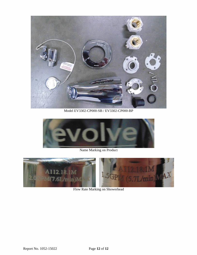
6.1 The tub spout flow-reduction systems were permanently marked with the manufacturer’s name “evolve” on the spout and the maximum flow rate on the showerhead.
6.2 The markings were permanent, legible and visible after installation. Note: The maximum flow rate marking requirement is not applicalbe to models EV3302-CP000-SB and EV3302-CP000-BP since they are not provided with a showerhead and are not intended to be used to limit the flow.
ASME A112.18.1-2012/CSA B125.1-12 4.1 Supply Fittings
4.1.1 Rated Pressure – COMPLIED
4.1.1.1 The tub spout flow-reduction systems were designed for a rated pressure of 100 psi.
4.1.1.2 The tub spout flow-reduction systems were designed to function at a supply pressure between 20 psi and 125 psi.
4.1.2 Rated Temperatures – COMPLIED
The tub spout flow-reduction systems were designed for rated supply temperatures from 40 F to 160 F.
4.2 Servicing – COMPLIED
The tub spout flow-reduction systems were designed so that the replacement of wearing parts could be accomplished without removing the fitting from the supply system, without removing the piping from the body, without disturbing the finished wall, and by using standard tools or manufacturer provided tools.
4.3 Installation – COMPLIED A method of sealing between the fitting and the fixture to which it is fastened was provided. 4.4 Threaded Connections – COMPLIED
4.4.1 The ½” (female inlet and male outlet) and ¾” (female inlet) NPT pipe threads complied with ASME B1.20.1. 4.4.9 The showerheads were capable of being connected to a ½” NPT male thread.

Report No. 1052-15022 Page 5 of 12
4.5 Other Connections – COMPLIED
4.5.4 The ½” and ¾” slip-fit joints met the performance requirements of this Standard.
4.7 Backflow Prevention – COMPLIED The tub spout flow-reduction systems were designed to prevent backflow as required by an air gap when evaluated per Clause 5.9. Refer to Clause 5.9.
4.8 Cover Plates and Escutcheons – COMPLIED
4.8.2 The minimum diameter of the escutcheon was 3.62”. The minimum requirement was 1.73”.
4.9 Toxicity and Lead Content
4.9.1 NSF/ANSI 61-9 – NOT APPLICABLE
The NSF/ANSI 61-9 test is not applicable to shower fittings.
4.9.2 Metal Alloys – COMPLIED
All metal alloys in contact with potable water contained less than 8% lead as required.
Findings: The brass spout inlet adapters contained 2.028% lead, spout shaft contained 3.138% lead, spout shaft fitting contained 2.654% lead, sensing element contained 0.170% lead, NC valve body contained 2.023% lead, NC valve ½” NPT inlet fitting contained 2.295% lead, and NC valve inner body fitting contained 3.346% lead. The zinc spout body contained 0.025% lead. The stainless steel sensing element fitting and spring contained 0.000% lead. No solder and flux were used.
4.9.3 NSF/ANSI 372 – NOT APPLICABLE
The NSF/ANSI 372 test is not applicable to shower fittings. 4.11 Shower Heads
4.11.1 General – COMPLIED
The flow-restricting insert of the showerheads was mechanically retained at the point of manufacture to withstand a removal force of not less than 8.0 lbf (36 N).
Note: The flow restrictor which is inserted in the ball joint can’t be accessible without disassembling the showerhead.
4.11.2 High-Efficiency Shower Heads – NOT APPLICABLE
The supplied showerheads were not designated as a high-efficiency type. 4.12 Cross-flow – COMPLIED
The flow-control device [normally-closed (NC) trickle valve] did not completely shut off the flow of water.

Report No. 1052-15022 Page 6 of 12
5.1 General – FOLLOWED Before testing, specimens were conditioned at ambient laboratory conditions for not less than 12 h. All applicable tests were conducted in accordance with Table B.1 of this standard.
5.2 Coatings (Chrome Finish)
5.2.1 General – COMPLIED
The significant surfaces of the coated components were free of surface defects and uncoated areas, and were not stained.
5.2.2 Corrosion – COMPLIED
After being subjected to the corrosion test of ASTM B117 (neutral salt) for Service Condition 2 for 24 h as specified in Clause 5.2.2.2.1, the coating did not show more than one surface defect in any 1.0 in2 area of the significant surface or up to three surface defects on a 1.0 inch length of parting line. The surface defects were not larger than 0.03 inch any dimension.
5.2.3 Adhesion – COMPLIED
5.2.3.2 The coating on metals met the grind-saw test requirements as defined in ASTM B 571. 5.2.3.3 The coating on plastics met the following thermal cycling test requirements when tested per Clause 5.2.3.3.2.
a) No surface defects such as cracks, blisters, peeling, or discoloration on significant surfaces.
b) No cracks longer than 0.25 in with a loss of adhesion between the base material and the coating.
c) No blisters exceeding 0.01 in2 in area within 0.25 inch of an injection point.
d) No warpage affecting the performance of the fitting or component.
5.3 Pressure and Temperature
5.3.1 Static and Dynamic Seals – COMPLIED
The seals of the tub spout flow-reduction systems did not leak or otherwise fail when tested in accordance with Clauses 5.3.1.3 and 5.3.1.4 of the standard. The test pressure was applied at 20 psi and 125 psi for 5 minutes each with the spout in closed position.
Note: The showerheads of the tub spout flow-reduction systems were tested with flowing pressures as the outlet is difficult to block.
5.3.6 Diverters – COMPLIED
The rate of leakage out of the tub spout of the bath and shower diverter did not exceed 0.1 gpm when tested in accordance with Clause 5.3.6.1.2.
Finding: The rate of leakage out of the spout was 0.0 gpm. 5.4 Flow Rate – COMPLIED
5.4.1 The tub spout flow-reduction systems met the flow rate requirments as specified in Table 1, at the temperatures and flowing pressures specified in Clause 5.4.2.3.

Report No. 1052-15022 Page 7 of 12
Finding:
Model No. Measured Flow Rate at 20 psi from Spout
(Min. Required = 2.4 gpm)
Measured Flow Rate from Showerhead
Min. Measured Flow Rate at 45 psi
(For Information Only)
Max. Measured Flow Rate at 80 psi
(Max. Allowed = 2.5 gpm)
EV3312-CP150-SB
> 12.0 gpm
1.3 gpm (Single Mode) 1.3 gpm (Single Mode)
EV3312-CP200-SB 1.8 gpm (Single Mode) 1.9 gpm (Single Mode)
EV3322-CP150-SB 1.3 gpm
(in Center Spray Mode) 1.3 gpm
(in Outer Spray Mode)
EV3322-CP200-SB 1.7 gpm
(in Center Spray Mode) 1.9 gpm
(in Outer Spray Mode)
EV3302-CP000-SB N/A N/A
EV3302-CP000-BP
Note: The water saving mode designed to flow less than 0.5 gpm at 80 psi (on models EV3322-CP150-SB and EV3322-CP200-SB only) is excluded from the minimum flow requirement at 45 psi per the standard.
5.5 Operating Requirements – COMPLIED
5.5.1 The tub spout flow-reduction systems were operable with a torque not exceeding that in Table 2 when tested at the temperatures and pressures specified in Clause 5.3.1.4.
Finding: The maximum operating torque was 2.0 lbf-in for the normally-closed valve control.
Note: The operating requirement for tub-to-shower diverters is exempted per the standard.
5.6 Life Cycle 5.6.1.5 Diverters – NOT APPLICABLE
The life cycle test for the auto-diverting diverter of the tub spout flow-reduction systems is exempted per Section 4.2 (a) of IAPMO IGC 244-2015a. Note: The thermostatic shut-off valve (temperature actuated valve) that is integrated into the tub spout will automatically close and divert water to the showerhead position when the inlet water supply temperature reaches at about 96.0 °F to 97.0 °F.
5.6.3.3 Other Devices (In-line Flow Control Device) – COMPLIED
The in-line flow control device (normally-closed valve) was tested to 15,000 cycles. During and after the test, the control mechanism continued to function as at the beginning of the test and did not develop any defects that could adversely affect its functionality or serviceability.After the test, the operating torque was 1.0 lbf-in when tested in accordance with Clause 5.5 of the standard.
5.7 Resistance to Installation Loading 5.7.2 Thread Torque Strength – COMPLIED
5.7.2.1 The ½” and ¾” NPT metal threaded connections withstood a torque load of 45 lbf-ft and 65 lbf-ft, respectively as specified in Table 4 of the standard without evidence of cracking or separation.

Report No. 1052-15022 Page 8 of 12
5.7.2.2 The threaded connections intended to seal water did not crack, strip, or leak when tested in accordance with Clause 5.3.1.3 with the threaded connection tightened to (a) the torque required to affect the seal; and (b) 150% of the torque required by Item (a).
5.7.2.3 NOT APPLICABLE – Clause 5.3.2 (Burst Pressure Test) only applies to threaded supply connections intended for use under continuous pressure. The tub spout flow-reduction systems are not intended for use under continuous pressure application.
5.8 Resistance to Use Loading
5.8.1 Operating Controls – COMPLIED
5.8.1.3 The operating controls that can not be grasped withstood an axial load of 10 lbf without pulling off.
5.9 Backflow Prevention – COMPLIED 5.9.2 Fittings with Plain Outlets – COMPLIED
The tub spout flow-reduction systems were designed to prevent backflow from the outlet with an air gap in accordance with ASME A112.1.2. The actual air gap was dependent on field installation.
6.0 Markings
6.1 General – COMPLIED
6.1.1 The tub spout flow-reduction systems were permanently marked with the manufacturer’s name “evolve” on the spout body. The marking was visible after installation.
6.1.2 The showerheads were marked with the manufacturer’s specified maximum flow rate, in L/min and gpm, in accordance with Clause 5.4.2.3.2(a).
6.3 Packaging – COMPLIED
6.3.1 NOT EVALUATED – The packaging shall be marked with the manufacturer’s name or trademark as well as the model number.
Finding: No formal production packaging was received for review.
6.3.2 The packaging or other included literature shall be marked with the following:
(a) the manufacturer’s specified maximum flow rate determined in accordance with Clause 5.4.2.3.2(a); and
(b) the statement “For use with automatic compensating valves rated at xxx L/min (yyy gpm) or less”, where xxx L/min (yyy gpm) is the lowest minimum flow rate recorded in accordance with Clause 5.4.2.3.2(b).
Finding: The user guide was marked with the manufacturer’s specified maximum flow rate as specified in Clause 6.3.2(a) and the statement as specified in Clause 6.3.2(b).

Report No. 1052-15022 Page 9 of 12
ASSE 1062-2006 3.1 Working Pressure Test – COMPLIED
The device (integrated into tub spout) was installed per Figure 1 and tested per Section 3.1.2 of this standard at the pressure of 125.0 psi for 1.5 minutes.
Finding: No indication of leakage or damage was observed.
Note: Per Section 4.2 (b) of IAPMO IGC 244-2015a, the test was conducted at 125.0 psi as specified in Clause 5.3.1.4.2 of ASME A112.18.1-2012/CSA B125.1-12.
3.2 Deterioration at Extremes of Manufacturer’s Temperature and Pressure – COMPLIED
The device (integrated into tub spout) was set up per Figure 1 and tested per Section 3.2.2 of this standard at 125.0 psi and 150.0 °F for 30 minutes.
Finding: No indication of leakage or damage was observed.
Note: Per Section 4.2 (b) of IAPMO IGC 244-2015a, the test was conducted at 125.0 psi and 150.0 °F as specified in Clause 5.3.1.4.2 of ASME A112.18.1-2012/CSA B125.1-12.
3.3 Flow Rate Test – COMPLIED
The device (integrated into tub spout) was set up per Figure 2 and tested per Section 3.3.2 of this standard.
Finding: The flow rate at 20 psi was more than 12.0 gpm, which met the minimum flow rate requirement of 2.4 gpm as specified in ASME A112.18.1-2005/CSA B125.1-05 for tub spouts.
3.4 Flow Reduction and Reset Test – NOT APPLICABLE
The test procedure outlined in Section 3.4.2 indicates to initiate the water flow at 104.0 °F ± 5.0 °F through the device. However, the device that is integrated into the tub spout will fully close and divert water to the showerhead position when the inlet water supply temperature reaches at about 96.0 °F to 97.0 °F. Therefore, this test can not be conducted. Section 4.2 (b) of the primary standard IAPMO IGC 244-2015a requires the device only to comply with the applicable requirements of ASSE 1062. Therefore, this test is considered not applicable.
3.5 Life Cycle Test – NOT APPLICABLE
The life cycle test is exempted per Section 4.2 (b) of IAPMO IGC 244-2015a.
3.6 Hydrostatic Pressure Test – COMPLIED
The device (integrated into tub spout) was pressurized with water at ambient temperature to 125.0 psi for one minute with the outlet blocked and the device fully open.
Finding: No leakage through the device was observed.
Note: Per Section 4.2 (b) of IAPMO IGC 244-2015a, the test was conducted at 125.0 psi as specified in Clause 5.3.1.4.2 of ASME A112.18.1-2012/CSA B125.1-12.

Report No. 1052-15022 Page 10 of 12
4.1 Materials in Contact with Water – COMPLIED (For Whole Tub Spout)
All metal alloys in contact with potable water contained less than 8% lead as required.
Findings: The brass NPT inlet adapters contained 2.028% lead, shaft contained 3.138% lead, shaft fitting contained 2.654% lead, sensing element contained 0.170% lead. The zinc body contained 0.025% lead. The stainless steel sensing element fitting and spring contained 0.000% lead. No solder and flux were used.
Note: The device is intended for shower applications, not intended to be used for dispensing water for human consumption.
4.2 Coatings – COMPLIED (Chrome Finish)
The coating complied with the applicable requiremnents specified in Clause 5.2 of ASME A112.18.1-2005/CSA B125.1-05 when tested in accordance with that Clause.
Finding: Clause 5.2 of ASME A112.18.1-2005/CSA B125.1-05
5.2.2 General – COMPLIED
The significant surfaces of the coated components were free of surface defects and uncoated areas, and were not stained.
5.2.2 Corrosion – COMPLIED
After being subjected to the corrosion test of ASTM B117 (neutral salt) for Service Condition 2 for 24 h as specified in Clause 5.2.2.2.1, the coating did not show more than one surface defect in any 1.0 in2 area of the significant surface or up to three surface defects on a 1.0 inch length of parting line. The surface defects were not larger than 0.03 inch any dimension.
5.2.4 Adhesion – COMPLIED
5.2.3.2 The coating on metals met the grind-saw test requirements as defined in ASTM B 571.
5.2.3.3 The coating on plastics met the following thermal cycling test requirements when tested per Clause 5.2.3.3.2.
a) No surface defects such as cracks, blisters, peeling, or discoloration on significant surfaces.
b) No cracks longer than 0.25 in with a loss of adhesion between the base material and the coating.
c) No blisters exceeding 0.01 in2 in area within 0.25 inch of an injection point.
d) No warpage affecting the performance of the fitting or component.
4.3 Markings – NOT APPLICABLE
The primary standard used for the testing of the device is IAPMO IGC 244-2015a. The device should be evaluated to the marking requirements of IAPMO IGC 244-2015a.
4.4 Installation Instructions – COMPLIED
4.4.1 Complete instructions for installation was packaged with the device. Drawings and schematic sketches which would be useful to the installer are part of these instructions. These instructions provide all information necessary for correct installation.
4.4.2 The installation instructions indicate the tested and approved installation position of the device.

Report No. 1052-15022 Page 11 of 12
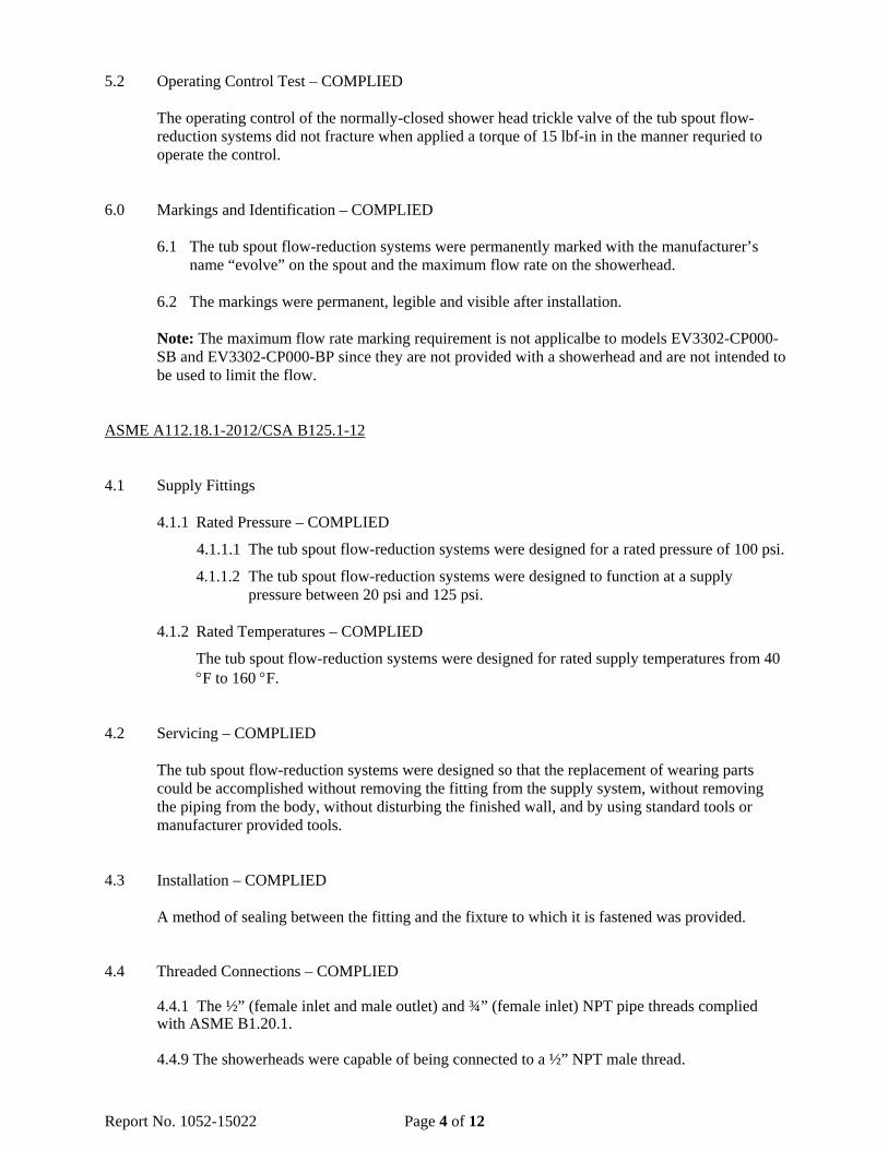
Photographs of Samples Tested:
Model EV3312-CP150-SB / EV3312-CP200-SB
Model EV3322-CP150-SB / EV3322-CP200-SB
Report No. 1052-15022 Page 12 of 12
Model EV3302-CP000-SB / EV3302-CP000-BP
Name Marking on Product
Flow Rate Marking on Showerhead