Report no. changed (Mar 2006): SM-324-UU
37
SACLANTCEN MEMORANDUM serial no.: SM-324 SACLANT UNDERSEA RESEARCH CENTRE MEMORANDUM SCATTERING BY SPHERES BUWED IN SEDIMENT H. T. Tamasauskas, J. A. Fawcett January 1997 The S A C I A M Undersea Research Centre provides the Supreme Allid cpr&,ander Atlantic (SACLANT) with scientific and technical assistance under the teri'ms taf .: its NATO charter, which entered into force on 1 February 1963: Without,p~ejudice !' to this main task - and under the policy direction'of SACLANT - the'Cer;ltre also renders scientific and technical assistance to -the individual ~ ~ ~ ? . n a t i o n s : " : .I '. *' Report no. changed (Mar 2006): SM-324-UU
Transcript of Report no. changed (Mar 2006): SM-324-UU
SACLANTCEN MEMORANDUM serial no.: SM-324
SACLANT UNDERSEA RESEARCH CENTRE MEMORANDUM
SCATTERING BY SPHERES BUWED IN SEDIMENT
H. T. Tamasauskas, J. A. Fawcett
January 1997
The SACIAM Undersea Research Centre provides the Supreme Allid cpr&,ander Atlantic (SACLANT) with scientific and technical assistance under the teri'ms taf .:
its NATO charter, which entered into force on 1 February 1963: Without,p~ejudice !' to this main task - and under the policy direction'of SACLANT - the'Cer;ltre also renders scientific and technical assistance to -the individual ~ ~ ~ ? . n a t i o n s : " :
. I ' . * '
Report no. changed (Mar 2006): SM-324-UU
This document is approved for public release. Distribution is unlimited
SACLANT Undersea Research Centre Vide San Bartolomeo 400 19138 San Bartolomeo (SP), Italy
tel: +39-187-540.111 f a : +39-187-524.600
e-mail: [email protected]
NORTH ATLANTIC TREATY ORGANIZATION
Report no. changed (Mar 2006): SM-324-UU
N A T O UNCLASSIFIED
Scattering by spheres buried in sediment
H. T. TarnaSauskas and John A. Fawcett
The content of this document pertains to work performed under Project 033-3 of the SACLANTCEN Programme of Work. The document has been approved for release by The Director, SACLANTCEN.
Jan L. Spoelstra Director
N A T O UNCLASSIFIED
Report no. changed (Mar 2006): SM-324-UU

NATO UNCLASSIFIED
intentionally blank page
N A T O UNCLASSIFIED
Report no. changed (Mar 2006): SM-324-UU
N A T O UNCLASSIFIED
Scat te r ing by spheres bur ied in sed iment
H. T . Tamaiauskas and John A. Fawcett
Execut ive Summary: Mines often become buried in bottom sediment. Thus it is important to understand how burial affects the amplitude and spec- tral characteristics of the energy backscattered by a mine so that techniques for hunting these mines can be improved. The computational method, described in this report, models the energy scattered by a buried, elastic-shelled sphere. This modelling gives insight into the environmental and geometrical factors which significantly affect the characteristics of scattering from buried mines.
This report briefly describes the theory and implementation of an algorithm which models the scattering of energy from a sphere located below a wa- terlsediment interface. For a particular sphere, the computed spectra of the backscattered energy are presented for a variety of environmental and geomet- rical parameters, such as: sediment compressional speed, sediment attenuation, burial depth, and incident beam directionality. Also examined is the issue of the importance of multiple reflections between the buried mine and the nearby interface.
N A T O UNCLASSIFIED
Report no. changed (Mar 2006): SM-324-UU

intentionally blank page
N A T O UNCLASSIFIED
N A T O UNCLASSIFIED
Report no. changed (Mar 2006): SM-324-UU
N A T O UNCLASSIFIED
Scat te r ing b y spheres bur ied in sed iment
H. T . Tamaiiauskas and John A. Fawcett
Abstract : In this report the scattering of acoustic energy by an elastic sphere buried in sediment is examined. The geoacoustic model consists of two homogeneous fluid halfspaces separated by an intermediate layer. The source field is generated by either a point source or a vertical line array placed in the upper halfspace. The spherical shell is placed in the lower fluid halfspace and the scattered field is computed at an observation point placed at various locations in the upper halfspace.
The scattered field is computed with a modified T-matrix based approach. We examine how the physical parameters of the sediment (attenuation, density and velocity) and geometrical parameters such as the burial depth and the insonification angle, affect the backscattered field amplitude. The numerical results presented in this report are for an evacuated, steel shell that has a thickness of 3% of the outer radius.
Keywords: Scattering, sphere, buried
Henriette T . Tamaiauskas was a research assistant at SACLANTCEN during the summer of 1996. She is currently at The Technical University of Denmark, Department of Industrial Acoustics, Bld. 425, 2800 Lyngby, Denmark.
N A T O UNCLASSIFIED
Report no. changed (Mar 2006): SM-324-UU
NATO UNCLASSIFIED
Contents
1 Introduction
2 Theory 2.1 The scattering geometry . . . . . . . . . . . . . . . . . . . . . . . . . . . . . . 2.2 The T-matrix method . . . . . . . . . . . . . . . . . . . . . . . . . . . . . . .
The effect of geoacoustic and geometrical parameters on the backscattered field 6 3.1 Basement sound speed and attenuation . . . . . . . . . . . . . . . . . . . . . . 6 3.2 An intervening sediment layer . . . . . . . . . . . . . . . . . . . . . . . . . . . 12 3.3 Burial depth . . . . . . . . . . . . . . . . . . . . . . . . . . . . . . . . . . . . 14 3.4 Receiver location . . . . . . . . . . . . . . . . . . . . . . . . . . . . . . . . . . 17 3.5 Using a source array . . . . . . . . . . 19
4 The importance of rescattering terms
5 Summary
6 Acknowledgments
References
NATO UNCLASSIFIED
Report no. changed (Mar 2006): SM-324-UU
NATO UNCLASSIFIED
Introduction
The scattering of acoustic energy from an elastic-shelled sphere in an infinite fluid has been studied in the past by various authors (see for instance [I] for a broad overview of this subject). It has been found that an elastic-shelled object can have a complex frequency response. The characteristics of this response have been utilized by some researchers (e.g., [2], Ch.14) as data for object classification. However, in oceanic settings, the scattering objects may often be buried in the bottom sediment; hence, it is important to understand how burial affects the amplitude and the spectral characteristics of the backscattered energy.
The computational approach used in this report is based on the work of Lim et al. [3]. A FORTRAN implementation of the algorithm of this paper was provided to us by R. Lim. The method uses a modification of the free-space T-matrix technique [4] to account for the effect of interfaces on the incident and scattered fields. In order to do this, the theory relies heavily upon the expansions of cylindrical wavefield functions in terms of spherical wavefield functions and vice versa.
The surrounding sediment has two major effects upon the spectral response of an object to incident energy. First, the parameters of the fluid surrounding the object are different to those of water and hence the local free-field response of the object is different. Second, the waterlsediment interface changes the character of the incident field from the water column (and also the scattered field propagating back into the water column). For example, increasing the sound speed in the bottom will cause a ray path joining the source to the sphere to have a longer segment in the bottom, and as a result this incident energy will undergo greater attenuation in an attenuating sediment.
In the numerical examples, we first consider the effects of changing the parameters of a surrounding homogeneous fluid. In this case there is no waterlsediment interface. Next, a similar investigation of parameters is carried out with an upper water half- space of fixed sound speed and density and a lower sediment half-space. We examine two different basic geometries: (1 ) a point source directly above the sphere (normal incidence), (2) an offset point source giving a nominal grazing angle of 20'. In the latter case, the variation of the velocity in the sediment can have a dramatic effect on the propagation path of the energy in the sediment. We also consider the case of a sphere buried in a basement with an intervening sediment layer above.
NATO UNCLASSIFIED
Report no. changed (Mar 2006): SM-324-UU
NATO UNCLASSIFIED
Besides the environmental parameters, there are various geometrical parameters of interest such as burial depth, receiver position and source length for the case of a vertical line source. We examine some of the effects of varying these parameters. We have made a simple modification to the original code to allow us to plot two- dimensional slices of the scattered field at a single frequency.
Finally, we present some examples of the importance of the rescattering terms to the scattered field. The "primary" scattering from the buried sphere consists of the incident field transmitted through the interface, a single scattering from the sphere, and transmission of the upgoing wavefield back into the water column. There are also a sequence of reflections of the scattered field from the basementlwater interface and then rescattering from the sphere. All these interactions are accounted for in the modified T-matrix approach of [3]; however, it is interesting to observe how important these terms are to the total solution. It is possible with the computer code to compute only the primary scattering term. The issue of the importance of the multiple scattering terms is of practical interest from a modelling point of view. If modelling only the primary scattering from the object is sufficiently accurate, then the modelling can be simplified. An appropriate propagation code can be used to compute the field incident upon the object, a standard free-space scattering code can be used to compute the field scattered by the object, and then a propagation code can be used to propagate this scattered field throughout the oceanic waveguide. This type of approach has been implemented in, for example, [5] and [6].
The geoacoustic model used in this report is a totally fluid one (however, the model for the sphere is fully elastic). Thus we are assuming that the effects of shear in the medium surrounding the sphere can be negligible. We are also ignoring any poro- elastic effects, and the interfaces are assumed to be smooth and flat. These features may, in fact, become relatively important when the acoustic energy in the sediment is evanescent and very small in amplitude. Lim [7] has generalized the algorithm used in this paper to include the effects of poro-elasticity.
NATO UNCLASSIFIED
Report no. changed (Mar 2006): SM-324-UU
N A T O UNCLASSIFIED
Theory
In this section the basic theory of computing the field scattered from a buried, elastic object will be briefly outlined (See refs. [3, 81 for more details, including the setup of the equations).
2.1 T h e scattering geometry
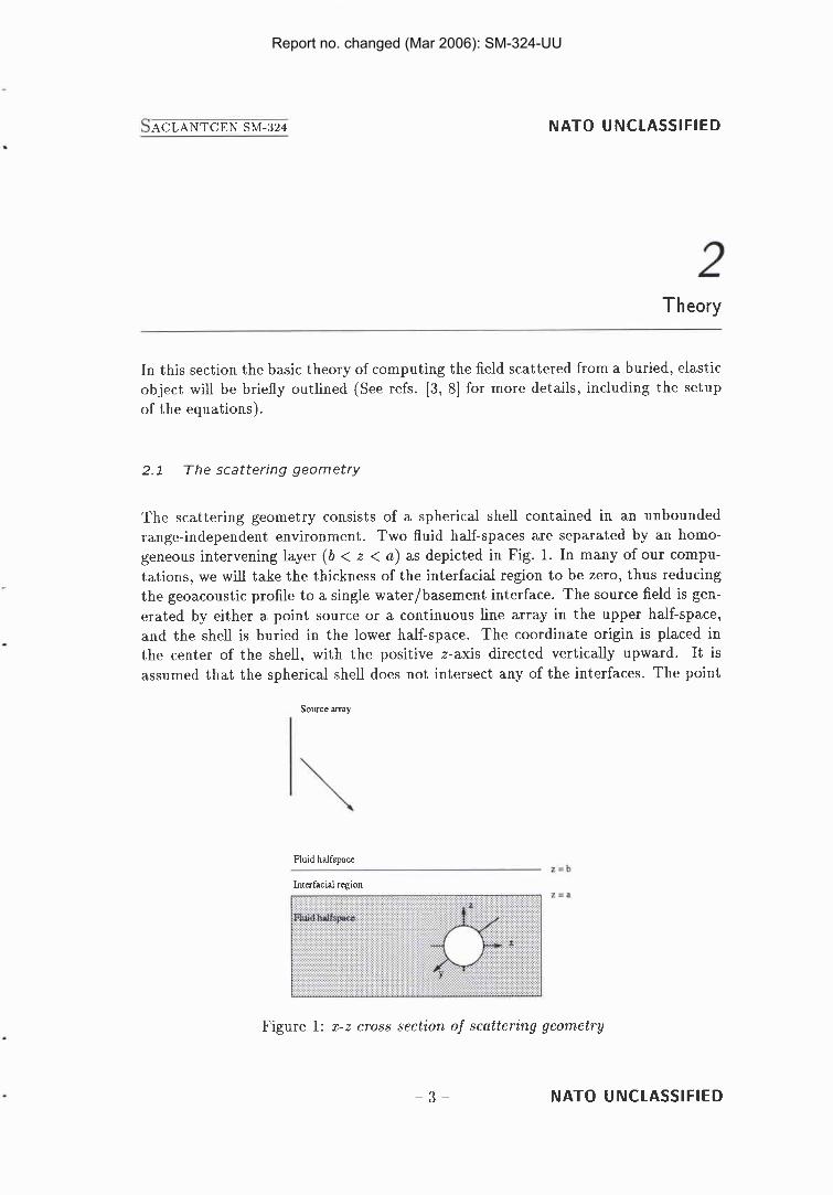
The scattering geometry consists of a spherical shell contained in an unbounded range-independent environment. Two fluid half-spaces are separated by an homo- geneous intervening layer ( b < z < a ) as depicted in Fig. 1. In many of our compu- tations, we will take the thickness of the interfacial region t o be zero, thus reducing the geoacoustic profile to a single waterlbasement interface. The source field is gen- erated by either a point source or a continuous line array in the upper half-space, and the shell is buried in the lower half-space. The coordinate origin is placed in the center of the shell, with the positive z-axis directed vertically upward. It is assumed that the spherical shell does not intersect any of the interfaces. The point
Source m y
Fluid halfspace
Interfacial region
Figure 1: z-z cross section of scattering geometry
N A T O UNCLASSIFIED
Report no. changed (Mar 2006): SM-324-UU
N A T O U NCLASSlFlED
source (or in the case of a vertical line array, the midpoint of the array) is placed at the cylindrical coordinates r,= (<,, c$,, z,), while the observation point, where the scattered field is detected, is placed at (C, 4, z ) . By using a line array it is possible to produce a bounded source beam, which can be phase steered to examine specific areas of the bottom.
2.2 T h e T - m a t r i x method
In free space, scattering from a spherical shell can be solved straightforwardly by the T-matrix method. Following the notation of Ref. [3], the incident field is expanded in terms of a basis set of functions $ym,l where
jl is a regular spherical Bessel function, YU,,,1 is a normalized spherical harmonic and k = 2nlX is the wavenumber. The spherical harmonic functions are defined by
cos m4, a = 0 x PIm (cos 6) sin m4, a = 1
where the Neumann factor E, is equal to 2 for m > 0 and equal to 1 for m = 0 and Plm are the Legendre polynomials. In Eq. (2) the parity index a is equal to zero or one (even or odd trigonometric functions), the rank index m is in the interval 0 5 m < 1 and the order index 1 has a integer value in the interval 0 5 1 < oo. Thus, the incident wavefield, pZnc, has an expansion of the form
where the U ~ ~ , , ~ ' S are the expansion coefficients.
The scattered field is similarly expanded in terms of a basis set This basis set is formed by using the spherical Hankel functions (in order to satisfy the outgoing radiation condition) in conjunction with the spherical harmonics. The compressional and shear potentials within the layers of the sphere are expanded in terms of spherical harmonic basis sets with unknown coefficients. By invoking the elastic continuity conditions at each interface of the spherical scatterer, a system of linear equations is obtained for these coefficients. In particular, the expansion coefficients of the
N A T O UNCLASSIFIED
Report no. changed (Mar 2006): SM-324-UU
NATO UNCLASSIFIED
exterior scattered field can be related to the expansion coefficients of the incident field via the so-called T-matrix T,,,,J;~I,~I,JI,
For a buried sphere, the scattering problem in the neighbourhood of the sphere is the same as the free space problem. However, the incident field which has been transmitted into the sediment from the water column above is most easily expressed as an integral of cylindrical basis functions (radial Bessel functions in conjunction with vertical plane- waves). It is, however, possible to express this cylindrical basis set of functions in terms of the basis set of regular spherical harmonics. Similarly, the spherical basis set can be expressed in terms of an integral of the cylindrical functions. This expansion can be used to propagate the scattered field, which is computed in terms of the spherical harmonics basis set, through the interface (i.e., applying the appropriate plane-wave transmission coefficient to each component) back into the water.
A fraction of the field scattered from the buried sphere will reflect back from the surrounding interfaces towards the sphere, where it will be rescattered, etc. In order to incorporate this rescattered energy into the T-matrix formalism, it is necessary to describe the conversion of an outgoing spherical basis function into incident basis functions at an interface. This rescattering operator R is then included in the T- matrix formalism, yielding an effective T-matrix, Te where
In order to compute this rescattering operator, the outgoing spherical basis functions are expressed as integrals of the cylindrical functions over horizontal wavenumber. These integrands can be multiplied by the plane-wave reflection coefficient as a function of wavenumber to determine the reflected field. Then by re-expanding this resultant integrand in terms of the regular spherical basis set, the rescattering operator can be determined. Each of the elements of R is given by an integral over wavenumber of products of Legendre polynomials. For more details of the relationships between cylindrical and spherical harmonic representations and of the representation of the rescattering operator R, see [3, 81.
NATO UNCLASSIFIED
Report no. changed (Mar 2006): SM-324-UU
NATO UNCLASSIFIED
The effect of geoacoustic and geometrical parameters on the backscattered field
In this section we examine, through numerical examples, the effect of various envi- ronmental and geometrical factors on the pressure field backscattered from a buried sphere. Reference [3] also examines some of these parameters.
The sphere in all our computations is steel-shelled with an evacuated interior and radius a m. The steel shell has a thickness of 3% of the outer radius. The acousto- elastic properties of the steel shell are fixed throughout this report at V, = 5790 m/s, Vs= 3100 m/s and p = 7.9 g/cm3. The steel is taken to have no attenuation.
As discussed in the theory, the scattered pressure field is expressed in terms (at least, in the vicinity of the sphere) of spherical harmonic functions. In Eq.(3) we used the truncation criterion I,,, = 3 + ka + 4.05(ka)'/~ as suggested by Kargl and Marston [9] and also used in [3]. For example, for ka = 60 this means that b,,, = 78. For a given value of I the maximum order m is, in general, equal to I. However, in the case that the source is located on the z-axis (i.e., normal incidence), the scattered field is azimuthally symmetric about the z-axis and only the m = 0 term is required in the series solution of Eqs. (1) and (2). The computation times are much less in this case.
3.1 Basement sound speed and attenuation
Normal incidence
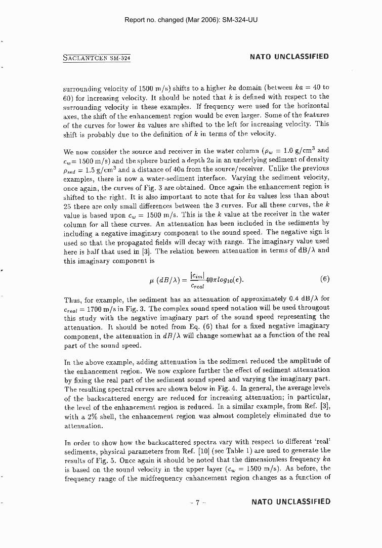
For the computations of this section, the incident field is from a point source that is located 40a directly above the center of the sphere (on the z-axis). The backscattered field amplitude is calculated at the source position (source and receiver position coincide) and plotted as a function of ka (k = w l c ) . In order to examine the effect of the surrounding sound speed, without the additional effects of interface transmission and reflection, we first consider free-field computations. Varying the free-field velocity (the density is fixed at 1.0 g/cm3) we obtain the results of Fig. 2. It can be seen that the so-called enhancement region (between ka = 30 to 50 for a
NATO UNCLASSIFIED
Report no. changed (Mar 2006): SM-324-UU
NATO UNCLASSIFIED
surrounding velocity of 1500 m/s) shifts to a higher ka domain (between ka = 40 to 60) for increasing velocity. It should be noted that k is defined with respect to the surrounding velocity in these examples. If frequency were used for the horizontal axes, the shift of the enhancement region would be even larger. Some of the features of the curves for lower ka values are shifted to the left for increasing velocity. This shift is probably due to the definition of k in terms of the velocity.
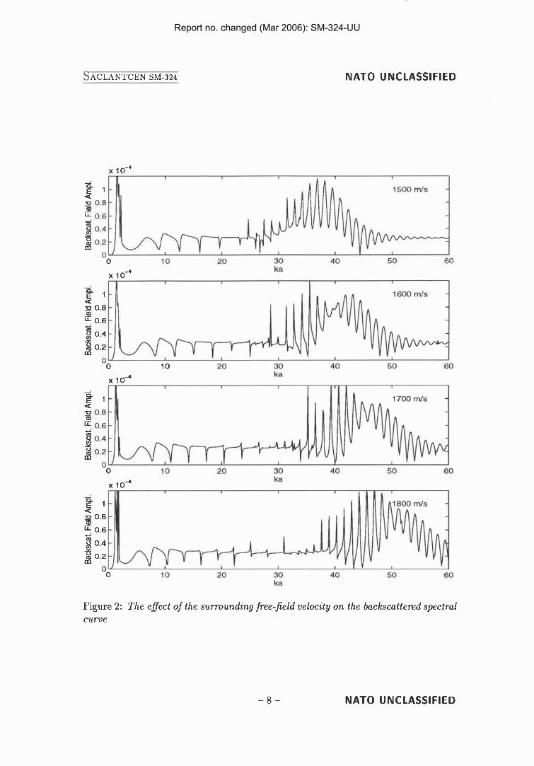
We now consider the source and receiver in the water column (p , = 1.0 g/cm3 and c,= 1500 m/s) and the sphere buried a depth 2a in an underlying sediment of density psed = 1.5 g/cm3 and a distance of 40a from the source/receiver. Unlike the previous examples, there is now a water-sediment interface. Varying the sediment velocity, once again, the curves of Fig. 3 are obtained. Once again the enhancement region is shifted to the right. It is also important to note that for ka values less than about 25 there are only small differences between the 3 curves. For all these curves, the k value is based upon c, = 1500 m/s. This is the k value at the receiver in the water column for all these curves. An attenuation has been included in the sediments by including a negative imaginary component to the sound speed. The negative sign is used so that the propagated fields will decay with range. The imaginary value used here is half that used in [3]. The relation beween attenuation in terms of dB/X and this imaginary component is
Thus, for example, the sediment has an attenuation of approximately 0.4 dB/X for ere,, = 1700 m/s in Fig. 3. The complex sound speed notation will be used througout this study with the negative imaginary part of the sound speed representing the attenuation. It should be noted from Eq. (6) that for a fixed negative imaginary component, the attenuation in dB/X will change somewhat as a function of the real part of the sound speed.
In the above example, adding attenuation in the sediment reduced the amplitude of the enhancement region. We now explore further the effect of sediment attenuation by fixing the real part of the sediment sound speed and varying the imaginary part. The resulting spectral curves are shown below in Fig. 4 . In general, the average levels of the backscattered energy are reduced for increasing attenuation; in particular, the level of the enhancement region is reduced. In a similar example, from Ref. [3], with a 2% shell, the enhancement region was almost completely eliminated due to attenuation.
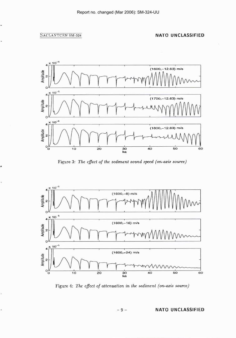
In order to show how the backscattered spectra vary with respect to different 'real' sediments, physical parameters from Ref. [ l o ] (see Table 1) are used to generate the results of Fig. 5 . Once again it should be noted that the dimensionless frequency ka is based on the sound velocity in the upper layer (c, = 1500 m/s). As before, the frequency range of the midfrequency enhancement region changes as a function of
- 7 - NATO UNCLASSIFIED
Report no. changed (Mar 2006): SM-324-UU
NATO UNCLASSIFIED
x lo4 ka i - e 1 - 4 1600 I ds -
4: q 0.8 - - 0.6 - I -
4 3 0.4 - Y % 0.2 -,
1 m I I , '
10 20 30 40 60 60
Figure 2: The effect of the surrounding free-field velocity on the backscattered spectral curve
NATO UNCLASSIFIED
Report no. changed (Mar 2006): SM-324-UU
NATO UNCLASSIFIED
Figure 3: The effect of the sediment sound speed (on-axis source)
Figure 4: The effect of attenuation in the sediment (on-axis source)
NATO UNCLASSIFIED
Report no. changed (Mar 2006): SM-324-UU
NATO UNCLASSIFIED
Gravel 2.00 1800
Table 1: Material parameters of sediments used for Fig. 5
x lo-' 4 I 1 1 1 1 I I I I
a Sand
Gravel .d
90 too
Figure 5 : The backscattered spectra for three dinerent sediments
sediment type and this feature has been very reduced in amplitude in all 3 curves due to the significant attenuation in these sediments. However, the character of the spectral response is very similar for all the curves for ka values less than 30.
NATO UNCLASSIFIED
Report no. changed (Mar 2006): SM-324-UU
NATO UNCLASSIFIED
Non-normal incidence
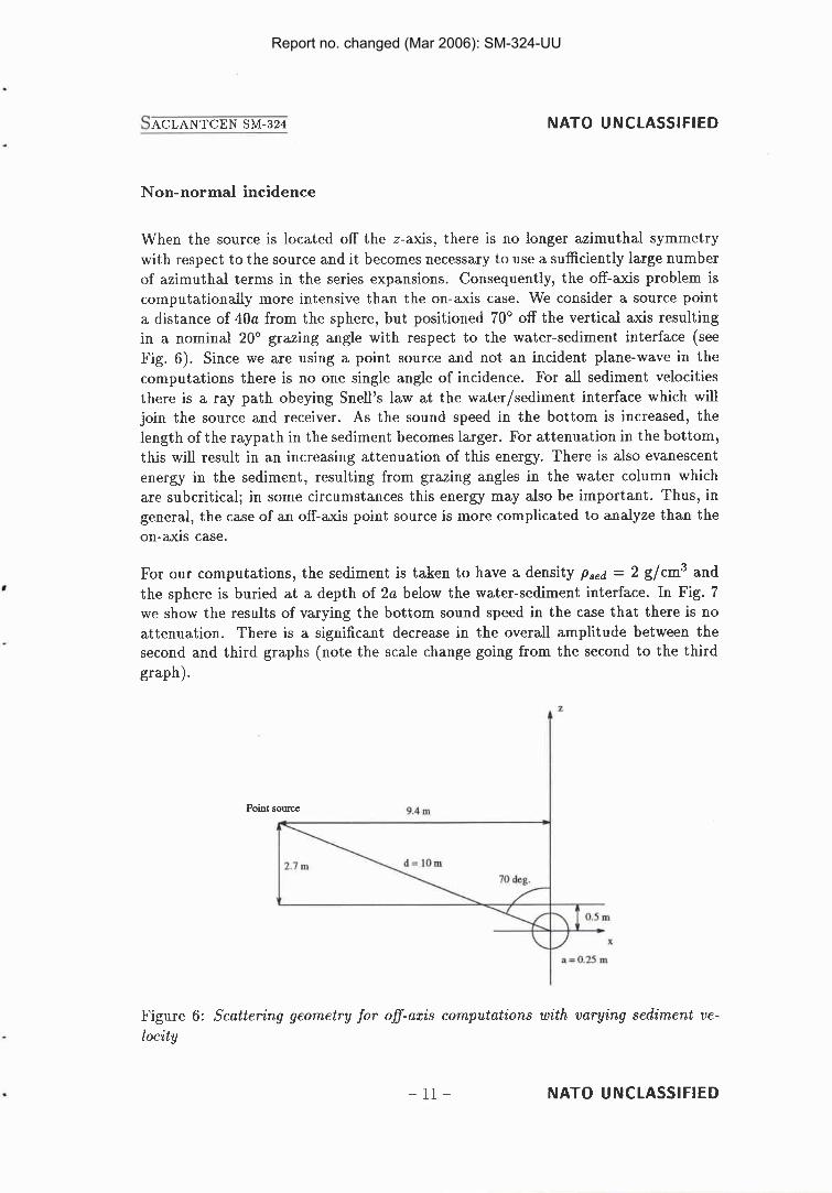
When the source is located off the z-axis, there is no longer azimuthal symmetry with respect to the source and it becomes necessary to use a sufficiently large number of azimuthal terms in the series expansions. Consequently, the off-axis problem is computationally more intensive than the on-axis case. We consider a source point a distance of 40a from the sphere, but positioned 70' off the vertical axis resulting in a nominal 20' grazing angle with respect to the water-sediment interface (see Fig. 6). Since we are using a point source and not an incident plane-wave in the computations there is no one single angle of incidence. For all sediment velocities there is a ray path obeying Snell's law at the waterlsediment interface which will join the source and receiver. As the sound speed in the bottom is increased, the length of the raypath in the sediment becomes larger. For attenuation in the bottom, this will result in an increasing attenuation of this energy. There is also evanescent energy in the sediment, resulting from grazing angles in the water column which are subcritical; in some circumstances this energy may also be important. Thus, in general, the case of an off-axis point source is more complicated to analyze than the on-axis case.
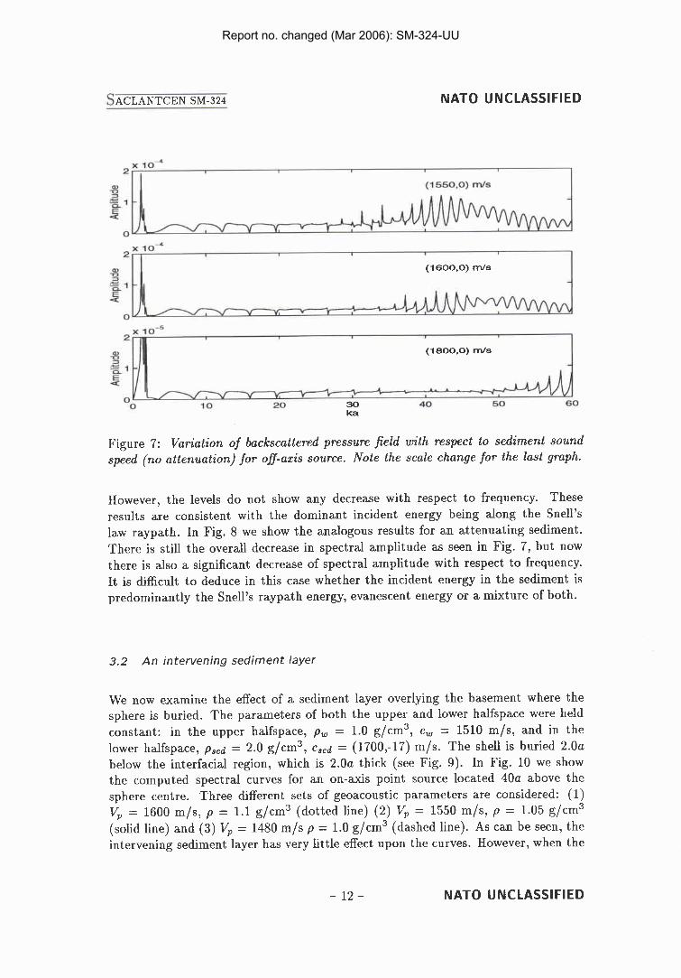
For our computations, the sediment is taken to have a density p,,d = 2 g/cm3 and the sphere is buried at a depth of 2a below the water-sediment interface. In Fig. 7 we show the results of varying the bottom sound speed in the case that there is no attenuation. There is a significant decrease in the overall amplitude between the second and third graphs (note the scale change going from the second to the third graph).
Point s o m 9.4 m
Figure 6: Scattering geometry for off-axis computations with varying sediment ve- locity
NATO UNCLASSIFIED
Report no. changed (Mar 2006): SM-324-UU
NATO UNCLASSIFIED
Figure 7: Variation of backscattered pressure field with respect to sediment sound speed (no attenuation) for off-axis source. Note the scale change for the last graph.
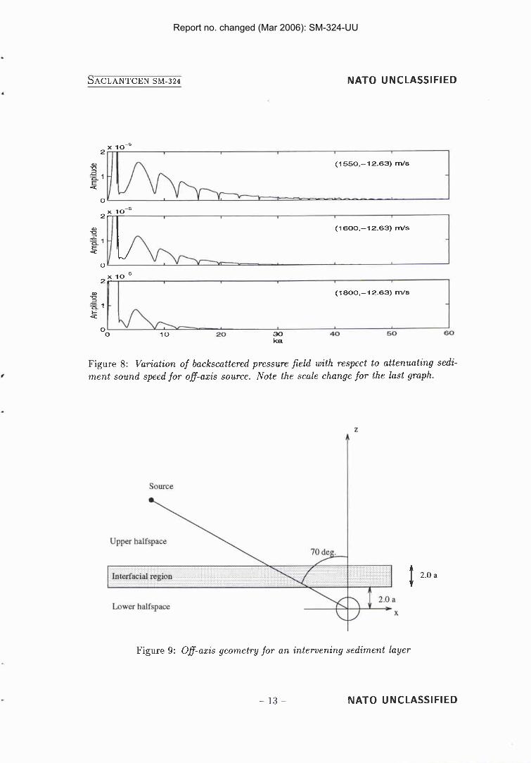
However, the levels do not show any decrease with respect to frequency. These results are consistent with the dominant incident energy being along the Snell's law raypath. In Fig. 8 we show the analogous results for an attenuating sediment. There is still the overall decrease in spectral amplitude as seen in Fig. 7, but now there is also a significant decrease of spectral amplitude with respect to frequency. It is difficult to deduce in this case whether the incident energy in the sediment is predominantly the Snell's raypath energy, evanescent energy or a mixture of both.
3.2 An intervening sediment layer
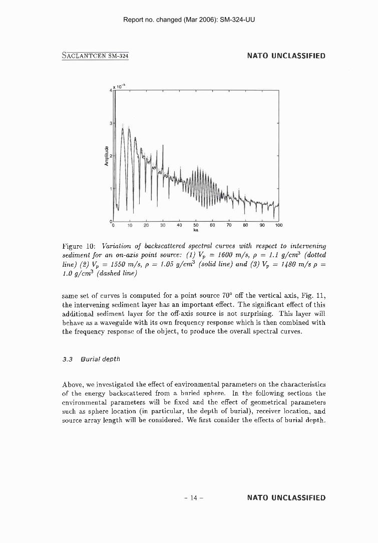
We now examine the effect of a sediment layer overlying the basement where the sphere is buried. The parameters of both the upper and lower halfspace were held constant: in the upper halfspace, p, = 1.0 g/cm3, c , = 1510 m/s, and in the lower halfspace, p,,d = 2.0 g/cm3, c,,d = (1700,-17) m/s. The shell is buried 2 . 0 ~ below the interfacial region, which is 2 . 0 ~ thick (see Fig. 9). In Fig. 10 we show the computed spectral curves for an on-axis point source located 40a above the sphere centre. Three different sets of geoacoustic parameters are considered: ( I ) Vp = 1600 m/s, p = 1.1 g/cm3 (dotted line) (2) Vp = 1550 m/s, p = 1.05 g/cm3 (solid line) and (3) Vp = 1480 m/s p = 1.0 g/cm3 (dashed line). As can be seen, the intervening sediment layer has very little effect upon the curves. However, when the
NATO UNCLASSIFIED
Report no. changed (Mar 2006): SM-324-UU
N A T O UNCLASSIFIED
Figure 8: Variation of backscattered pressure field with respect to attenuating sedi- ment sound speed for of-axis source. Note the scale change for the last graph.
Figure 9: Of-az is geometry for an intervening sediment layer
N A T O UNCLASSIFIED
Report no. changed (Mar 2006): SM-324-UU
NATO UNCLASSIFIED
Figure 10: Variation of backscattered spectral curves with respect to intervening sediment for an on-axis point source: (1) Vp = 1600 m/s, p = 1.1 g/cm3 (dotted line) (2) Vp = 1550 m/s, p = 1.05 g/cm3 (solid line) and (3) Vp = 1480 m/s p = 1.0 g/cm3 (dashed line)
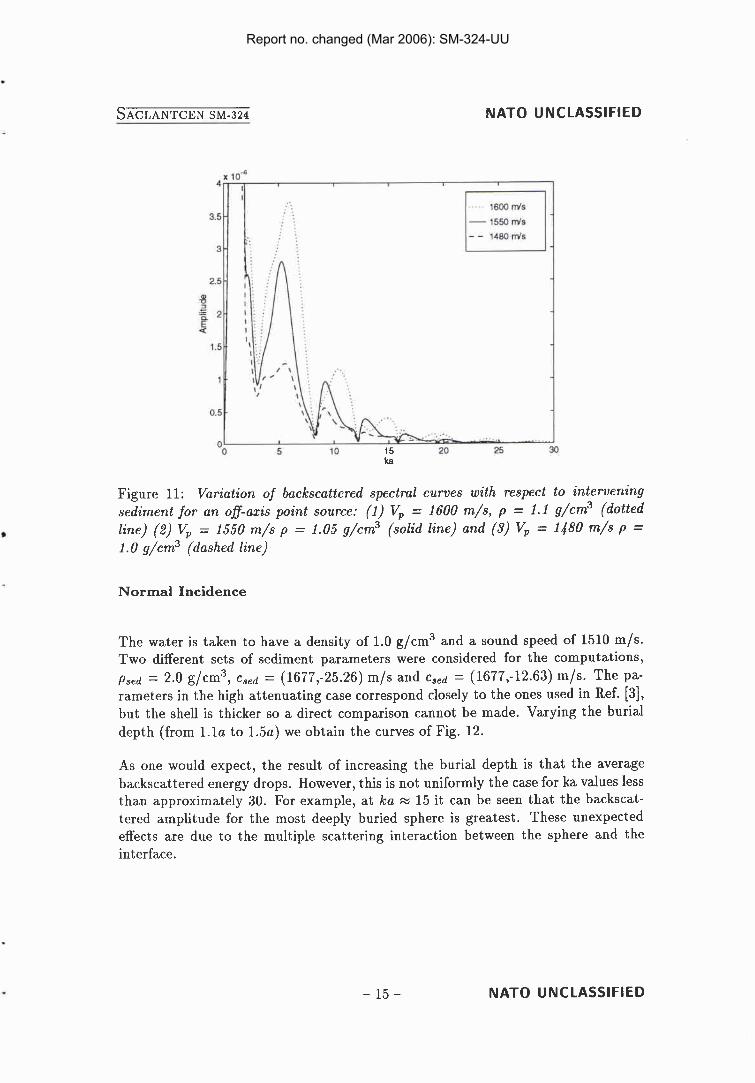
same set of curves is computed for a point source 70' off the vertical axis, Fig. 11, the intervening sediment layer has an important effect. The significant effect of this additional sediment layer for the off-axis source is not surprising. This layer will behave as a waveguide with its own frequency response which is then combined with the frequency response of the object, to produce the overall spectral curves.
3.3 Burial depth
Above, we investigated the effect of environmental parameters on the characteristics of the energy backscattered from a buried sphere. In the following sections the environmental parameters will be fixed and the effect of geometrical parameters such as sphere location (in particular, the depth of burial), receiver location, and source array length will be considered. We first consider the effects of burial depth.
NATO UNCLASSIFIED
Report no. changed (Mar 2006): SM-324-UU
NATO UNCLASSIFIED
Figure 11: Variation of backscattered spectral curves with respect to intervening sediment for an ofl-azis point source: (1) Vp = 1600 m/s, p = 1.1 g/cm3 (dotted line) (2) Vp = 1550 m/s p = 1.05 g/cm3 (solid line) and (3) Vp = 1480 m/s p = 1.0 g/cm3 (dashed line)
Normal Incidence
The water is taken to have a density of 1.0 g/cm3 and a sound speed of 1510 m/s. Two different sets of sediment parameters were considered for the computations, Psed = 2.0 g/cm3, csed = (1677,-25.26) m/s and cS,d = (1677,-12.63) m/s. The pa- rameters in the high attenuating case correspond closely to the ones used in Ref. [3], but the shell is thicker so a direct comparison cannot be made. Varying the burial depth (from l . l a to 1.5a) we obtain the curves of Fig. 12.
As one would expect, the result of increasing the burial depth is that the average backscattered energy drops. However, this is not uniformly the case for ka values less than approximately 30. For example, at ka = 15 it can be seen that the backscat- tered amplitude for the most deeply buried sphere is greatest. These unexpected effects are due to the multiple scattering interaction between the sphere and the interface.
NATO UNCLASSIFIED
Report no. changed (Mar 2006): SM-324-UU
NATO UNCLASSIFIED
in-5 Low attenuation
x lo4 High attenuation
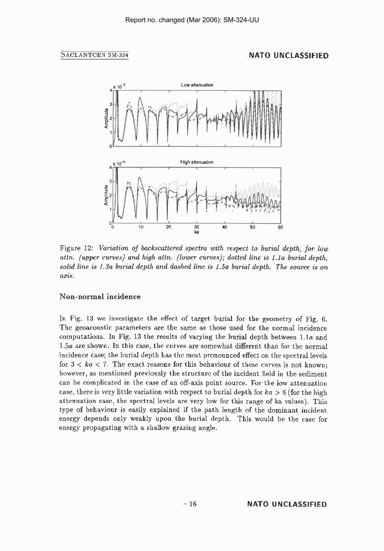
Figure 12: Variation of backscattered spectra with respect to burial depth, for low attn. (upper curves) and high attn. (lower curves); dotted line is 1 . 1 ~ burial depth, solid line is 1 . 3 ~ burial depth and dashed line is 1.5a burial depth. The source is on axis.
Non- normal incidence
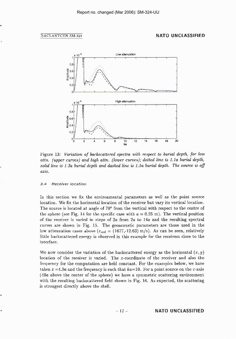
In Fig. 13 we investigate the effect of target burial for the geometry of Fig. 6. The geoacoustic parameters are the same as those used for the normal incidence computations. In Fig. 13 the results of varying the burial depth between l . l a and 1 . 5 ~ are shown. In this case, the curves are somewhat different than for the normal incidence case; the burial depth has the most pronounced effect on the spectral levels for 3 < ka < 7. The exact reasons for this behaviour of these curves is not known; however, as mentioned previously the structure of the incident field in the sediment can be complicated in the case of an off-axis point source. For the low attenuation case, there is very little variation with respect to burial depth for ka > 8 (for the high attenuation case, the spectral levels are very low for this range of ka values). This type of behaviour is easily explained if the path length of the dominant incident energy depends only weakly upon the burial depth. This would be the case for energy propagating with a shallow grazing angle.
NATO UNCLASSIFIED
Report no. changed (Mar 2006): SM-324-UU
NATO UNCLASSIFIED
x 10.' Low attenuation
10.' High attenuation
Figure 13: Variation of backscattered spectra with respect to burial depth, for low attn. (upper curves) and high attn. (lower curves); dotted line is 1 . 1 ~ burial depth, solid line is 1.3a burial depth and dashed line is 1.5a burial depth. The source is o f axis.
3.4 Receiver location
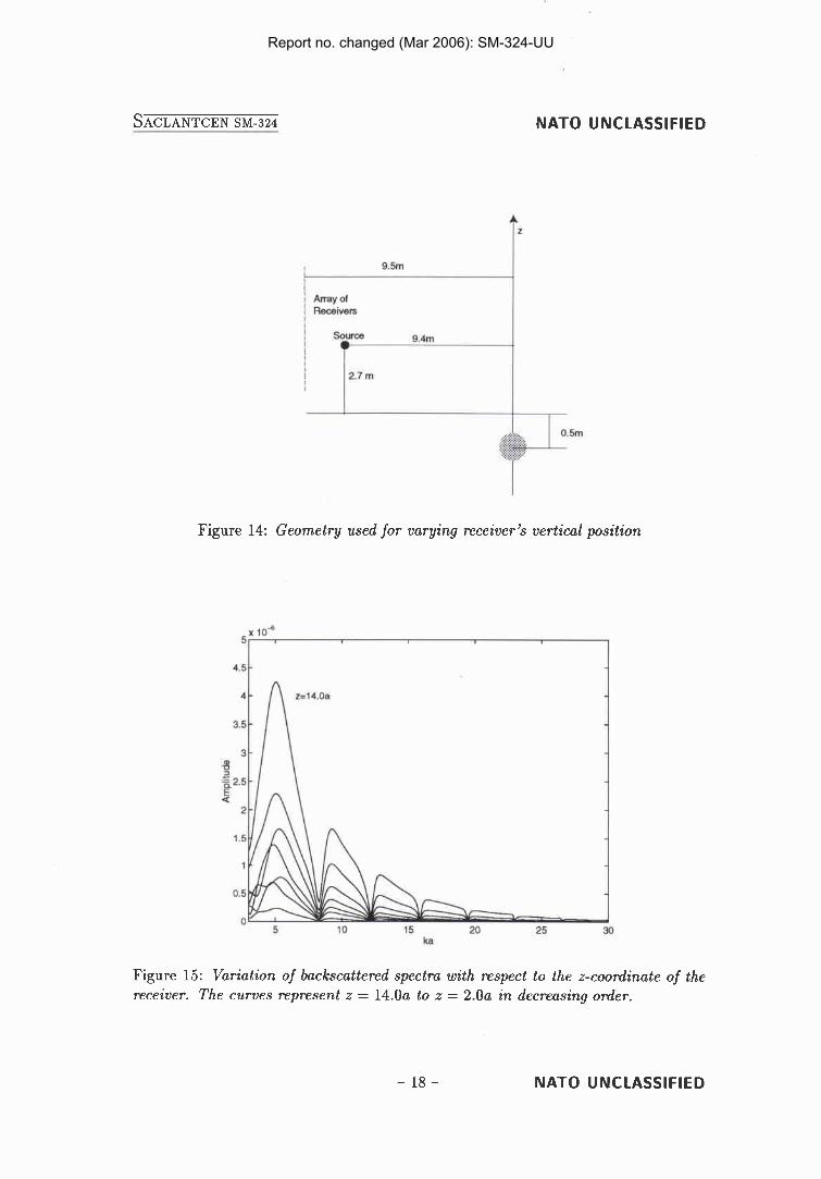
In this section we fix the environmental parameters as well as the point source location. We fix the horizontal location of the receiver but vary its vertical location. The source is located at angle of 70' from the vertical with respect to the centre of the sphere (see Fig. 14 for the specific case with a = 0.25 m). The vertical position of the receiver is varied in steps of 2a from 2a to 14a and the resulting spectral curves are shown in Fig. 15. The geoacoustic parameters are those used in the low attenuation cases above (csed = (1677,-12.63) m/s). As can be seen, relatively little backscattered energy is observed in this example for the receivers close to the interface.
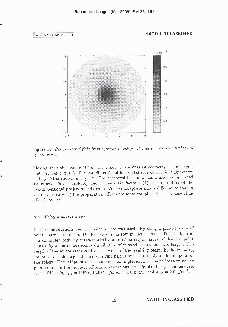
We now consider the variation of the backscattered energy as the horizontal (x, y) location of the receiver is varied. The z-coordinate of the receiver and also the frequency for the computation are held constant. For the examples below, we have taken z =4.0a and the frequency is such that ka=lO. For a point source on the z-axis (40a above the center of the sphere) we have a symmetric scattering environment with the resulting backscattered field shown in Fig. 16. As expected, the scattering is strongest directly above the shell.
NATO UNCLASSIFIED
Report no. changed (Mar 2006): SM-324-UU
NATO UNCLASSIFIED
Figure 14: Geometry used for varying receiver's vertical position
Figure 15: Variation of backscattered spectra with respect to the z-coordinate of the receiver. The curves represent z = 14.0a to z = 2 . 0 ~ in decreasing order.
NATO UNCLASSIFIED
Report no. changed (Mar 2006): SM-324-UU
N A T O UNCLASSIFIED
Figure 16: Backscattered field from symmetric setup. The axis units are numbers of sphere radii.
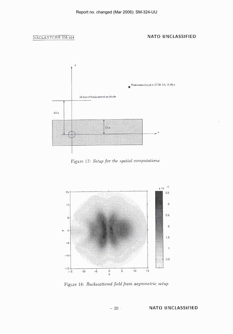
Moving the point source 70' off the z-axis, the scattering geometry is now asym- metrical (see Fig. 17). The two-dimensional horizontal slice of this field (geometry of Fig. 17) is shown in Fig. 18. The scattered field now has a more complicated structure. This is probably due to two main factors: (1) the orientation of the two-dimensional projection relative to the source/sphere axis is different to that in the on-axis case (2) the propagation effects are more complicated in the case of an off-axis source.
3.5 Using a source array
In the computations above a point source was used. By using a phased array of point sources, it is possible to create a narrow incident beam. This is done in the computer code by mathematically approximating an array of discrete point sources by a continuous source distribution with specified position and length. The length of the source array controls the width of the resulting beam. In the following computations the angle of the insonifying field is pointed directly at the midpoint of the sphere. The midpoint of the source array is placed in the same location as the point source in the previous off-axis examinations (see Fig. 6). The parameters are: c, = 1510 m/s, cs,d = (1677,-12.63) m/s, p, = 1.0 g/cm3 and ps,d = 2.0 g/cm3.
N A T O U NCLASSlFlED
Report no. changed (Mar 2006): SM-324-UU
N A T O UNCLASSIFIED
2d sbce of backscattered amphrudc
Point source (x,y,z) = (37 58. 0 0. 13 68) a
I
Figure 17: Setup for the spatial computations
X
?igure 18: Backscattered field from asymmetl pic setup
N A T O UNCLASSIFIED
Report no. changed (Mar 2006): SM-324-UU
NATO UNCLASSIFIED
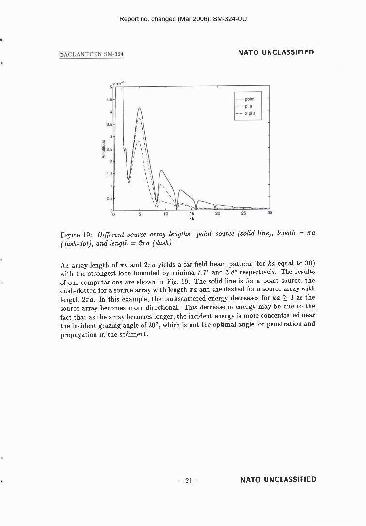
Figure 19: Diflerent source array lengths: point source (solid line), length = Ira (dash-dot), and length = 21ra (dash)
An array length of Ira and 27ra yields a far-field beam pattern (for ka equal to 30) with the strongest lobe bounded by minima 7.7' and 3.8' respectively. The results of our computations are shown in Fig. 19. The solid line is for a point source, the dash-dotted for a source array with length Ira and the dashed for a source array with length 27ra. In this example, the backscattered energy decreases for ka 2 3 as the source array becomes more directional. This decrease in energy may be due to the fact that as the array becomes longer, the incident energy is more concentrated near the incident grazing angle of 20°, which is not the optimal angle for penetration and propagation in the sediment.
NATO UNCLASSIFIED
Report no. changed (Mar 2006): SM-324-UU
NATO UNCLASSIFIED
The importance of rescattering terms
An approximation which is sometimes used when modelling the acoustic energy scattered by an object in a waveguide is to only include the effects of interfaces on the propagation of the incident field up to the scattering object and on the propagation of the scattered field away from the object. The scattering from the object is simply modelled as a free-space scattering process using the parameters of the surrounding medium. This type of methodology ignores any rescattering of energy back towards the object from the waveguide. However, this approximation allows one to use a number of standard propagation codes in combination with a free-space object scattering code. References [5] and [6] are two examples of this type of approach to waveguide scattering. In the computations presented below we compare the results obtained by using only the primary scattering term and by including all scattering terms.
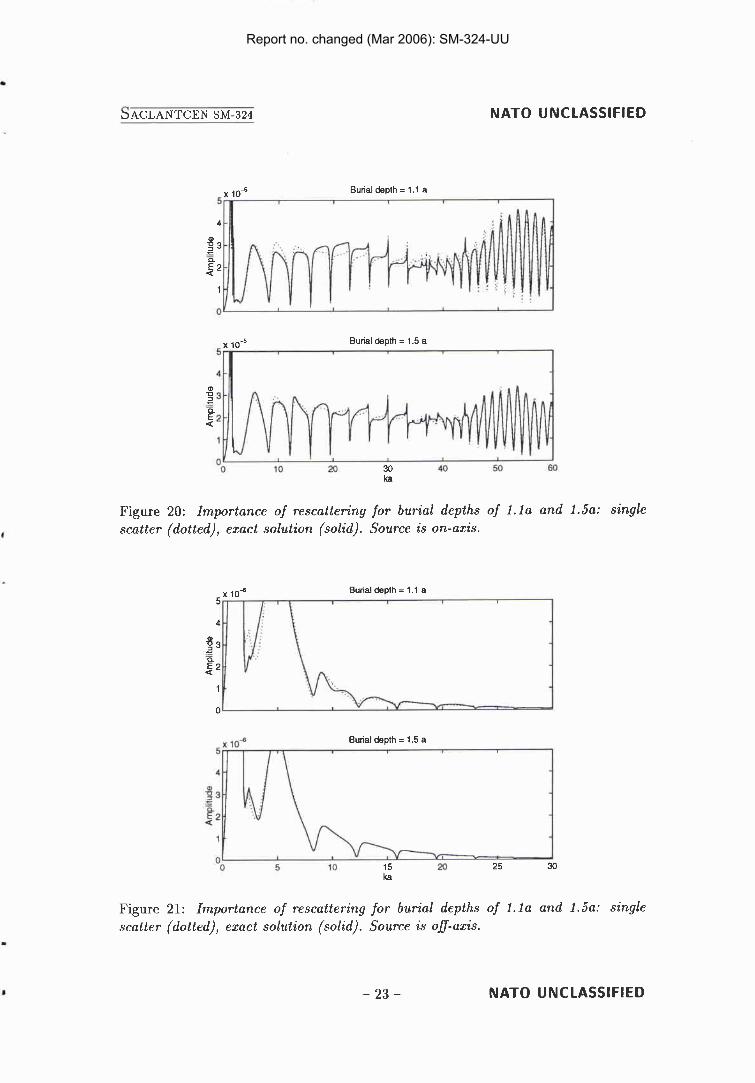
First, a point source is located on-axis a distance 40a above the centre of the sphere. The sound speed in the water is c, = 1510 m/s and p, = 1.0 g/cm3. The sound speed in the bottom is csed = (1677,-12.63) m/s and the density is pSed = 2.0 ,g/crn3. In Fig. 20 we show the spectral curves for burial depths of l . l a and 1 . 5 ~ using the single-scatter approximation (dotted line) and the exact solution (solid line). The differences between the single-scatter and exact curves are not large. They are most significant for the burial depth of 1.la and normal incidence where the difference between the 2 curves is as much as approximately 15% for some frequencies.
For Fig. 21 we repeat the above computations but for the source located 70' off axis. As can be seen the differences between the single-scatter and exact solutions are smaller for this case. For the burial depth of 1.5a the two curves are essentially identical.
NATO UNCLASSIFIED
Report no. changed (Mar 2006): SM-324-UU
NATO UNCLASSIFIED
in-5 Burial depth = 1 .I a
Burial depth = 1.5 a
I
Figure 20: Importance of rescattering for burial depths of 1 . la and 1.5a: single scatter (dotted), exact solution (solid). Source is on-axis.
x inb Burial depth = 1.1 a
Burial depth = I .5 a
Y I - A
20 25 30 ka
Figure 21: Importance of rescattering for burial depths of 1. l a and 1 . 5 ~ : single scatter (dotted), exact solution (solid). Source is off-axis.
NATO UNCLASSIFIED
Report no. changed (Mar 2006): SM-324-UU
NATO UNCLASSIFIED
5 Summary
We have examined the effects of various geoacoustic and geometric parameters on the spectral characteristics of the energy backscattered from a buried elastic-shelled sphere. For the 3% steel-shelled sphere considered in this study there was a par- ticular frequency interval (ka = 30 - 45 for co = 1500 m/s) over which strong resonances could be observed. This frequency region, which we referred to as the "enhancement region" was sensitive to the surrounding sediment's parameters. For an on-axis point source, increasing the sediment sound speed shifted the enhance- ment frequency region to higher frequency values. Attenuation in the sediment decreased the backscattered energy from the sphere with an increased effect for higher frequencies; the amplitude of the enhancement region is particularly sensi- tive to this parameter. However, the portion of the spectrum below ka = 25 was very stable with respect to the sediment parameters for the particular steel-shelled sphere considered in the computations of this study (we expect that this statement will depend somewhat upon the shell thickness, as the enhancement region is shifted to lower ka values for increasing thickness).
For a point source located 70" off axis, the sediment sound speed had a dramatic effect on the backscattered levels, both for non-attenuating and attenuating sedi- ments. For the non-attenuating sediment the levels were approximately constant as a function of frequency. For the attenuating sediment there was a drastic decrease in levels with increasing frequency. However, although the backscattered levels are significantly effected by the sediment sound speed and attenuation, the structure of the spectral curves (i.e., the pattern of peaks and nulls) remains stable.
We also investigated the effect of various geometrical factors; burial depth, receiver location, and source directionality. For the on-axis source and the sphere buried in an attenuating basement, the backscattered amplitude decreased, on average, with increasing burial depth. However, due to multiple scattering effects between the sphere and the interface there were frequencies for which this was not the case. For the off-axis source, the burial depth had a significant effect in the 4 < ka < 7 range and much less of an effect for higher ka values.
We also showed that the levels of the backscattered field varied significantly with receiver position (both vertically and horizontally) within the water column. For the examples of this paper, decreasing the beamwidth of a source beam (for a central
NATO UNCLASSIFIED
Report no. changed (Mar 2006): SM-324-UU
NATO UNCLASSIFIED
grazing angle of 20') decreased the backscattered amplitudes. This is probably due t o the fact that this grazing angle is, in fact, not optimal for penetration into the sediment (for the example considered) and hence eliminating the other grazing angles by decreasing the incident beamwidth decreases the amount of energy in the sediment.
Finally, we investigated the accuracy of using the single-scatter approximation for modelling. In the case of an on-axis source the single-scatter approximation yielded a fairly accurate scattering solution but there were differences in the details of the exact and single-scatter curves, especially for k a < 30. For the off-axis source the agreement was better and, in fact, the two curves were essentially identical for a burial depth of 1.5a. Thus, for the case of incident energy having small grazing an- gles, there is the possibility that the single-scatter approximation may be sufficiently accurate for many modelling scenarios.
NATO UNCLASSIFIED
Report no. changed (Mar 2006): SM-324-UU
Acknowledgments
NATO UNCLASSIFIED
The authors wish to thank Dr. Raymond Lim of Coastal Systems DivisionIDahlgren Division, Naval Surface Warfare Center, Panama City for the computer code used for this study. The authors would also like to express their gratitude to Francesco B. Verona, Peter Gerstoft and Peter L. Nielsen at SACLANT Centre for their sug- gestions, discussions and support.
NATO UNCLASSIFIED
Report no. changed (Mar 2006): SM-324-UU
NATO UNCLASSIFIED
References
[l] H. Uberall, editor. Acoustic Resonance Scattering. Gordon and Breach Science Publishers, 1992.
[2] N.D. Veksler. Resonance acoustic spectroscopy. Springer-Verlag, 1993.
[3] R. Lim, J.L. Lopes, R.H. Hackman, and D.G. Todoroff. Scattering by objects buried in underwater sediments: Theory and experiment. J. Acoust. Soc. Am., 93:1762-1783, April 1993.
[4] P.C. Waterman. New formulation of acoustic scattering. J. Acoust. Soc. Am., 45:1417-1429,1969.
[5] M.D. Collins and M.F. Werby. A parabolic equation model for scattering in the ocean. J. Acoust. Soc. Am., 85:1895-1902, 1989.
[6] F. Ingenito. Scattering from an object in a stratified medium. J. Acoust. Soc. Am., 82:2051-2059,1987.
[7] R. Lim. Scattering by an obstacle in a plane-stratified poroelastic medium: Application to an obstacle in ocean sediments. J. Acoust. Soc. Am., 95:1223- 1244, March 1994.
[8] R.H. Hackman and G.S. Sammelmann. Multiple-scattering analysis for a target in an oceanic waveguide. J. Acoust. Soc. Am., 84:1813-1825, November 1988.
[9] S.G. Kargl and P.L. Marston. Ray synthesis of lamb wave contributions to the total scattering cross section for an elastic spherical shell. J. Acoust. Soc. Am., 88:1103-1113, August 1990.
[lo] F.B. Jensen, W.A. Kuperman, M.B Porter, and H. Schmidt. Computational Ocean Acoustics. AIP Press, 1994.
NATO UNCLASSIFIED
Report no. changed (Mar 2006): SM-324-UU
NATO UNCLASSIFIED
Document Data Sheet NATO UNCLASSIFIED
H.T. Tamasauskas, J.A. Fawcett
Scattering - sphere - buried
North Atlantic Treaty Organization Tel: +39 (0) 187 540 1 1 1 SACLANT Undersea Research Centre Fax:+39 (0) 187 524 600 Viale San Bartolomeo 400, 19138 La Spezia,
E-mall. library saclantc.nato.~nt
[From N America. SACLANTCEN
Report no. changed (Mar 2006): SM-324-UU
Initial Distribution for SM-324
SCNR for SACLANTCEN SCNR Belgium SCNR Canada SCNR Denmark SCNR Germany SCNR Greece SCNR ltaly SCNR Netherlands SCNR Norway SCNR Portugal SCNR Spain SCNR Turkey SCNR UK SCNR US French Delegate SECGEN Rep. SCNR NAMILCOM Rep. SCNR
SACLANT
National Liaison Officers NLO Canada NLO Denmark NLO Germany NLO ltaly NLO Netherlands NLO UK NLO US
Total external distribution SACLANTCEN Library
.- pTotal number of copies
Report no. changed (Mar 2006): SM-324-UU


![UU PAPER-2 PCB Roll No. BA · 2-BA ] [ 3 ] [ P.T.O. UU UU UU UU UU UU UU UU UU UU UU UU UU 002. Two children Ramesh (on path ARB) and Sohan (on path ASB), travel down slides of identical](https://static.fdocuments.in/doc/165x107/5e1483c6a3dd674c594e381f/uu-paper-2-pcb-roll-no-ba-2-ba-3-pto-uu-uu-uu-uu-uu-uu-uu-uu-uu-uu-uu.jpg)