REPORT No. 492 - NASA · chord ratio (hereinafter referred to as the “thiclmess”), thethiclmess...
21
REPORT No. 492 TESTS OF 16 RELATED AIRFOILS AT HIGH SPEEDS By JOHN STACK and ALBERT E. VON DOmTHOFF SUMMARY In order to proti information thut rnighi lad to the devebpmeni of better propeller 8e4%i07w, 13 relaied eym- metrics.!airfoih haoe been tested in tha N.A.CA. high- Speedwind tunndfor a study oj thee$ect of thi&ne88form on th aerodynamicchuracteri.stti. The thicknas~orm variables stwdid were tb value of the maximum thtiknee8, the podion along the chord ai which the muximum thtikne88occur8, and the value of th leading-edgeradiw8. A 8y8temof equatbn8 wimwsed to dt$na the airfoil form so thutfair projil.e3havingq8tem- aiti clum.gtxwouldbe obtai~d. The bm”c thicknw form h VW nearly thi? same as that Gh08~ for the reeent invadigation of a lurge numbm of retied airfvil.ain the variabkd.endy wind tunnel (NA.CA. Tezhniuz.1Re- port No. 400). The tests were cundwcted.through the low angle-of- attack rangefor speeh aim.ding from 36 percent of that of 8owndto 81@t1y in a’.cem of the epeed at whicha eom- prew?ibi?tiyburble, or breaikihm of fiw, omurs. The corresponding Reynolde Number range ie 360,000 to ?’60,000. Became the ReyiwL_i2Numberfor the teet8ti somewhatlower thun that & iohich mo8tpropeUer8oper- ate, and much lower than thd at which aiqq?.anewings operaie, tlw dui!uare not directly applicubb to muny practical problems, hd it ia probalh thui 8ome of the re- latti 81wwn,particularly the relative eJe& of the 8hape clmnge8m a$eded by compra%-?riliiy,are valid & mwch higher vaLutxof tlu R.qvnoi2hNumber. The reeuh ob- tained were applied to the &@n of three camberedairfti which were te#ed m part of this invedigation. The principal fa&r8 a$ecting the choice of propellm 8ectiom are low drag at low and moderatelift toe-8 and a latecomprewi.bili.tyburble,thut%, low drag8at high 8peed8. COnwZ&g thae factor8, the rti indicate that the maximum thickne#8sho?dd be sm.al!and locuted at approximdely 40 percent of the chord afi of the leading edge. Sd variutti from the nomnal valwa for the leading-edge radim are 8h0wnto have wmz.?.l e$ect on the aerodynamti characterietim. A cornpankwnwith timil.ar tC8t8of comm07dyWW.ipropeller 8ec3%.7M lMkzltt% that & high speeck one of the cumbered airfo-ih tested, the N’,A.O.A. 2/.09-$4, h 8Upt7iW. The rt%uh d80 in- dicate thd 8om@furth?r improvement in ai?’fd 8hape8 for higlwpeed applicaiiom may be apected. INTRODUCTION Experimental investigations of the relationship be- tween airfoil shapes and airfoil aerodynamic character- istics have generally been made at some particular dynamic soale, or Reynolds Number, and usually ut relatively low speeds. Because the forces on an airfoil are afle@d by air compressibility, the speed at which teats are made may become an important parameter in the application of the results. It has been shown that the speed of flow expressed in terms of the speed of wave propagation, or the speed of sound, in the fluid is an index of the extent to which the flow is affected by com- pressibili~. Thus, the ratio of the flow velooity to the velocity of sound, V/Ve, is a parameter indicative of flow pattern similarity in relation to compressibility effecti just M the Reynolds Number is an index of the effects of viscosity. Therefore, if the speed at which the full-scale airfoil normally operates is greatly in ex- cess of the speed at which the model was tested, the test remlta maybe subject to a correction for the effects of compressibility. The importance of the compressibility effect cannot be disregarded for many modern applications. Previous airfoil tests over wide speed ranges (see reference 1) indicated that for speeds in excess of 300 miles per hour the compressibility effect on the airfoil characteristics may be large. It is therefore necessaxy to investigate the relationship between airfoil shape and the aero- dynamic characteristics at high speeds for such appli- cations as the design of propekwaj diving bombem, and high-speed racing airplanes. The aerodynamic characteristics of airfoils may be considered as being dependent on the thiclmess-to- chord ratio (hereinafter referred to as the “thiclmess”), the thiclmess distribution, and the mean-line shape. The present investigation was made to study the effects of changw in the thiolmeas and the thickness distribu- tion on the aerodynamic charaeterikks of airfoils, ,.,. partictiarly at high speeds, and to provide additional ‘ 1’ information for the study of compressibility phenom- ens. This information should lead to the design of better propeller sections. The effects of these changes were determined by tests over a wide speed range of 13 symmetrksd airfoils having systematic changea of threti variables. These variables are, for a iixed chord 339 https://ntrs.nasa.gov/search.jsp?R=19930091566 2020-01-04T14:11:12+00:00Z
Transcript of REPORT No. 492 - NASA · chord ratio (hereinafter referred to as the “thiclmess”), thethiclmess...
REPORT No. 492
TESTS OF 16 RELATED AIRFOILS AT HIGH SPEEDS
By JOHN STACK and ALBERT E. VON DOmTHOFF
SUMMARY
In order to proti information thut rnighi lad to thedevebpmeni of better propeller 8e4%i07w,13 relaied eym-metrics.!airfoih haoe been tested in tha N.A.CA. high-Speedwind tunndfor a study oj the e$ect of thi&ne88formon th aerodynamicchuracteri.stti.
The thicknas~orm variables stwdid were tb value ofthe maximum thtiknee8, the podion along the chord aiwhichthe muximumthtikne88occur8,and the value of thleading-edgeradiw8. A 8y8temof equatbn8 wimwsed todt$na the airfoilform so thutfair projil.e3havingq8tem-aiti clum.gtxwould be obtai~d. The bm”c thicknw formh VW nearly thi? same as that Gh08~ for the reeentinvadigation of a lurge numbm of retied airfvil.ain thevariabkd.endy wind tunnel (NA.CA. Tezhniuz.1Re-port No. 400).
The tests were cundwcted.through the low angle-of-attack rangefor speeh aim.ding from 36 percent of thatof 8owndto 81@t1y in a’.cem of the epeed at whicha eom-prew?ibi?tiyburble, or breaikihm of fiw, omurs. Thecorresponding Reynolde Number range ie 360,000 to?’60,000. Became the ReyiwL_i2Number for the teet8 tisomewhatlower thun that & iohich mo8tpropeUer8oper-ate, and much lower than thd at which aiqq?.anewingsoperaie, tlw dui!uare not directly applicubb to munypractical problems, hd it ia probalh thui 8ome of the re-latti 81wwn,particularly the relative eJe& of the 8hapeclmnge8m a$eded by compra%-?riliiy,are valid & mwchhigher vaLutxof tlu R.qvnoi2hNumber. The reeuh ob-tained wereapplied to the &@n of threecamberedairftiwhichwere te#ed m part of this invedigation.
The principal fa&r8 a$ecting the choice of propellm8ectiom are low drag at low and moderatelift toe-8and a late comprewi.bili.tyburble,thut%, low drag8at high8peed8. COnwZ&g thae factor8, the rti indicatethat the maximum thickne#8sho?dd be sm.al!and locutedat approximdely 40 percent of the chord afi of the leadingedge. Sd variutti from the nomnal valwa for theleading-edgeradim are 8h0wnto have wmz.?.le$ect on theaerodynamti characterietim. A cornpankwnwith timil.artC8t8of comm07dyWW.ipropeller 8ec3%.7MlMkzltt% that& high speeck one of the cumbered airfo-ih tested, theN’,A.O.A. 2/.09-$4, h 8Upt7iW. The rt%uhd80 in-
dicate thd 8om@furth?r improvement in ai?’fd 8hape8for higlwpeed applicaiiom may be apected.
INTRODUCTION
Experimental investigations of the relationship be-tween airfoil shapes and airfoil aerodynamic character-istics have generally been made at some particulardynamic soale, or Reynolds Number, and usually utrelatively low speeds. Because the forces on an airfoilare afle@d by air compressibility, the speed at whichteats are made may become an important parameter inthe application of the results. It has been shown thatthe speed of flow expressed in terms of the speed of wavepropagation, or the speed of sound, in the fluid is anindex of the extent to which the flow is affected by com-pressibili~. Thus, the ratio of the flow velooity to thevelocity of sound, V/Ve, is a parameter indicative offlow pattern similarity in relation to compressibilityeffecti just M the Reynolds Number is an index of theeffects of viscosity. Therefore, if the speed at whichthe full-scale airfoil normally operates is greatly in ex-cess of the speed at which the model was tested, thetest remlta maybe subject to a correction for the effectsof compressibility.
The importance of the compressibility effect cannotbe disregarded for many modern applications. Previousairfoil tests over wide speed ranges (see reference 1)indicated that for speeds in excess of 300 miles per hourthe compressibility effect on the airfoil characteristicsmay be large. It is therefore necessaxy to investigatethe relationship between airfoil shape and the aero-dynamic characteristics at high speeds for such appli-cations as the design of propekwaj diving bombem,and high-speed racing airplanes.
The aerodynamic characteristics of airfoils may beconsidered as being dependent on the thiclmess-to-chord ratio (hereinafter referred to as the “thiclmess”),the thiclmess distribution, and the mean-line shape.The present investigation was made to study the effectsof changw in the thiolmeas and the thickness distribu-tion on the aerodynamic charaeterikks of airfoils, ,.,.partictiarly at high speeds, and to provide additional ‘ 1’information for the study of compressibility phenom-ens. This information should lead to the design ofbetter propeller sections. The effects of these changeswere determined by tests over a wide speed range of 13symmetrksd airfoils having systematic changea of thretivariables. These variables are, for a iixed chord
339
https://ntrs.nasa.gov/search.jsp?R=19930091566 2020-01-04T14:11:12+00:00Z

. ..—— —..- ...- ..-—. . -—A . . . . .
340 REPORT NATIONAL ADVISORY COMMITTED FOR AERONAUTICS
length, the maggtude of the mtium thicknwa, theposition of the msximum thicknw, and the radius ofthe led.i.ng edge. Three cambered airfoils were alsotested as a prelhnimuy step in the investigation of theeffects of mean-ke shape on the aerodynamic charac-teristic at l@h speeds.
The tests consisted of the measurement of the lift,drag, and moment about the quartar+hord axis of themodels for a range of speeds extending from about 35percent of the speed of sound to speeds slightiy inexcess of the speed at which the breakdown of flowcorresponding to the compressibility burble occurred.The tests were conducted in the N.A.C.A. high-speedwind tunnel during 1932-33.
DESCRIPTION OF AIRFOILS
The variables herein considered as determmm..g thethickness form are the mtiurn thickmw, the posi-tion of the maximum thickness, and the radius of theleading edge expressed in terms of the chord. These
DESIGN NUMBERS
0006-63 0009-330012-63 0009-930009-63 0009-060009-62 0009-350008-64 0009-340009-65 2209-340009-66 2409-340009-03 4409-34
.
In the design numbers given above, the fhwt group offour digits gives the oamber and thiclmess designationand has the same significance as the airfoil designnumbers given in reference 1; that is, the tit digitindicates the mean camber in percent of the ohord;the second, the position of the camber in tenths of thechord aft of the leading edge; and the last two give themtium thiclmw in percent of the chord. Thegroup of digits following the dash designate the thick-ness distribution. The first digit designates the le&d-iqg-edge radius and the second digit gives the position
10– -+— +——+ _ N. A.C.A. 0020-63
‘~‘~+
+ N. A.C.A. 0020
~+>+
o
.---”~+”+
+~ ,?
-lo 1‘+---+.-+——=————— 1 1 10 10 20 30 40 50 ;0 70 80 90 100
~GUBEL—Ba.40tbfrkn~ dfstrfbtrtfonfor afrfollnkstai h the hfghuIEE3wfnd tmuml (N.A.Cl.A.IW2H3)mm- wftb MO thloknws dktrlbution for N.A.O.A.farnfly afrfotls (NAO.A. W referenm 2).
parameters detwmhing the thiclmess form so ex-pressed as ratios to the chord will throughout this re-port be referred to simply as “thickness”, “positionof mtium thiclmes”, and ‘%ading+dge radius.”Arbitrary values of these three variables were so chosenas to provide systematic variations over the entireprobable useful rnnge of forms. The resulting airfoilforms were defied by means of a system of equationsto insure fairnm of the prcdi.les, and the coefficientsof’ the various terms of the equations were determinedborn conditions imposed by the assumed values ofthe independent variables. The basic form is shownin figure 1. On the same figure the basic thicknessdistribution used in the investigation in reference 2 isalso shown. The leading-edge radius, the slope at thetail, the maximum thiclmess, the trailing+dge ordi-nate, and the position of the m&mum thickness weremade the wne as those of the basic form given inreference 2, which has been designated the “NA.C.A.0020 “ airfoil.
Range of forms.-The range of forms investigatedis shown by the airfoil design numbers in the followingtable:
of the maximum thickness in tenths of the chord nftof the leading edge.
The significance of the leading-edge radius designa-tion is given below-:
O designates sharp leading edge.3 d@rnatea one-fourth normal leading-edge
radius.6 designates normal leading-edge radius (the
lerding+xlge radius used in reference 2).9 designates three times normal leading-edge
radius or greater.
The leading-edge radius of the blunt-nosed airfoilused in this investigation is three ties the nornmlvalue.
Thus, the N.A.C.A. 0009-64 is a 9 percent thicksymmetxioal airfoil hwing a normal leading-edge radiusand its maximum th.iclmess 40 percent of the chordaft of the leading edge. The N.A.C.A. 2409-34 air-foil has a mtium mean camber of 2 percent locatedat 40 percent of the chord, and is 9 percent thick.The leading-edge radius is one-fourth of the normalvalue and the mtium thickness is located at 40 per-cent of the chord aft of the leading edge.

TESTS OF 16 RELATED AISFOIM AT HI(3H SPEEDS 341
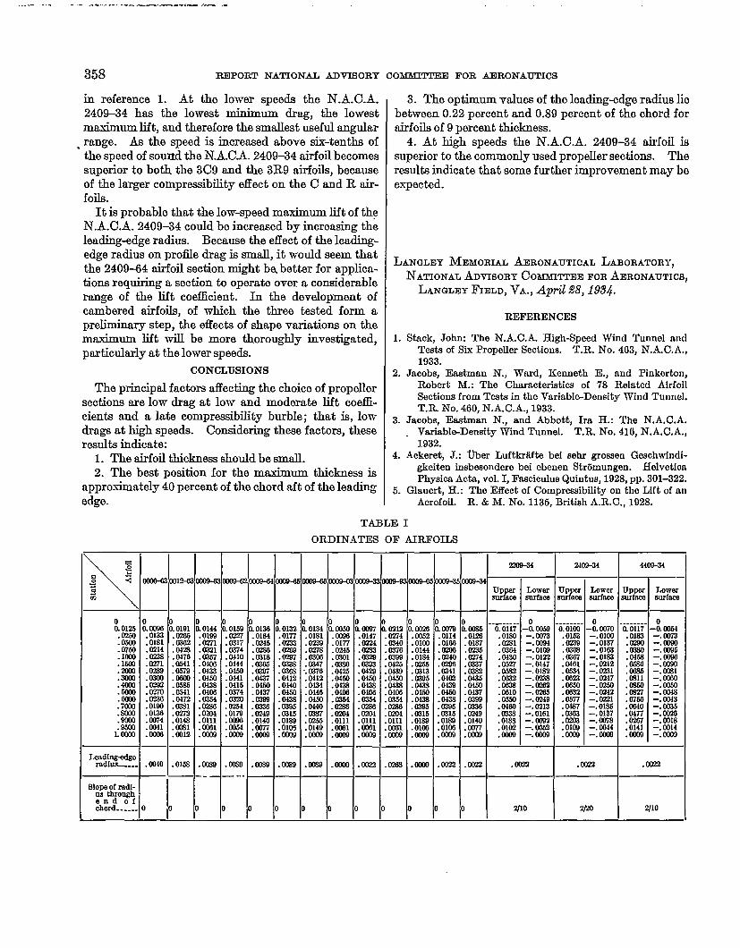
The range of thickness ratios tested in this investi-gation was small because it was considered necessaryto show only how relations already found for the tiectof thickness variation at low speeds are affected bycompressibility, and also because the airfoils chosen forhigh-speed application will of necessity be relativelythin. The value 09 of the maximum thiclmeag ratioof the airfoils designed for the study of variablesother than the maximum thiclmeas was chosen be-cause it is representative of the thiclmess range fromwhich airfoil sections for propellers would probablybe chosen. The airfoil profiles are shown in iigure 2,and the ordinates are given in table I.
Derivation of new thickness forms.-The airfoilforms tested in this investigation have been definedby two equations. Two equations were used ratherthan a single equation, because a single-equationsystem led to shape differences aft of the position ofmaximum thiclmcss when the leading-edge radius waschanged and also led to revenmls of curvature unless avery great number of terms were used.
If the chord is taken as the z axis from O to 1, theordinates y from the leading edge to the position ofmaximum thicluwas are given by an equation of theform
*y-~ Jz+u@+@+u& (1)The ordinates horn the position of maximum thicknessaft are given by an equation of the form
*y=&+ &(l–z)-t-dJl -@+dJl–~)8 (~)
The coefficients of the equation for the forwardportion are determined horn the following conditions:
(a) Maximum thicknessx=m y= 0.1 (where m is the location of the
maximum thicknaw in terms ofthe chord measured from theleading edge)
9.0dx .
(b) Lending-edge radiusThe leading-edge radius is derived from equa-
tion (1) and is $. Values of ~ chosen to
give certain desired leading-edge radii areshown in the following table:
sharp __... _ . . . . . ______________________(J= mmnd_...-_ . . . . . . . . . . . . . . -------.-- ------ ! ~=.................................------------- 6Ttuw tlnmn&--------------------------------- 9 .514246
(c) Radius of curvature at the point of maximumthickness
Radius of curvature at z = m,(1–m)’
‘=~~(1 –m) –o.588
GW6-63— .— . -— _ ..
0012-63
W09-63/.—
CW9-62
b09-64
0009-65
0009-66
0009-03
m9-33/
om9-93c●
<.—
0009-05
0009-35~
~.—.
cxlo9-34
FIGURE2—Akfd PIWflk*Tha N.A.O.A. WY&94Mu ban wViOUS&referredto as the N.A.O.A.204and
the N.A.O.A. 203S4, as the N.A.C.A. 216.
34!2 REPORT NATIONAL ADVISOBY COMMI’ITE E FOR AJIEONAUTICS
(this value is derived from the equation for theafter portion of the airfoil and is the same forboth equations at r= m).
The conditions that were taken to determine thecoefficients for the equation for the after portion are:
(a) Masimum thickness
~=yn, y=o.1 $=0
(b) Ordinate at trailing edgeX=1 y=c4=Jo.oo2
[c) Trailing-edge angle
X=1 @=d,=f(m)dx
The values of dl as a function of m, which were chosento avoid reversals of curvature, are given in the foUow-ing table:
Fm dl
a2 Cm&
:: .316.5 .465.6 .iCO
Substitution of the coefficients derived from theforegoing conditions in equations (1) and (2) givesequations for symmetrical airfoils 20 percent thick.These coefficients are given in table IL
The airfoil ordinates for any other thickness aredetermined by multiplying the ordinates derived from
the above equations by ~, where t is the airfoil thick-
n~ expressed as a fraction of the chord. The leading-
[1it’.edge radius for any- thickness is given by ~ ~
Derivation of cambered airfoils.-The three cam-bered airfoils were derived by combining one of thebest thiclmess forms, the 0009-34, with certain mean-line forms chosen fi-om reference 2. The mean lineschosen have the 2200, 2400, and 4400 forms. Themethods of combining the thiclmess distiution withthe mean-line forms are given in detail in reference 2.
APPARATUS AND METHOD
Apparatus,-A complete description of the high-speed wind tunnel and a detailed account bf themethod of conducting teds are given in reference 1.The models used for this investigation were of 2-inchchord .ud were made of steel. The method of con-structing the airfoils is described in reference 3.
Method of testing.-The teds consisted of the meas-urement of the lift, drqg, moment, and dynamic pres-sure for several speeds in the range *fig from 35percent of the speed of sound to speeds slightly inexcess of that at which the compressibility burbleoccurs. The corresponding Reynolds Number rangeis from 350,000 to 750,000. The angle~f-attack rangefor the tests of the symmetriod airfoils extended horn
– 4° to 4°. The additional tests required to determinothe mtium lift coe5cients would have unnecesmmi.lyprolonged the testing program because inferior airfoilsfor high-speed applications can be detected by theirearlier compressibility burble. The tests on the threecambered airfoils were conducted through the lowangle-f-attack rmge, and one of the three whichshowed promise as a practical propeller section waschosen for tests throughout the complete angle-of-attack range. The order of the tests was arranged, asfar as practicable, so that the tests to determine theeffects of a single variable were made consecutively.
RESULTS
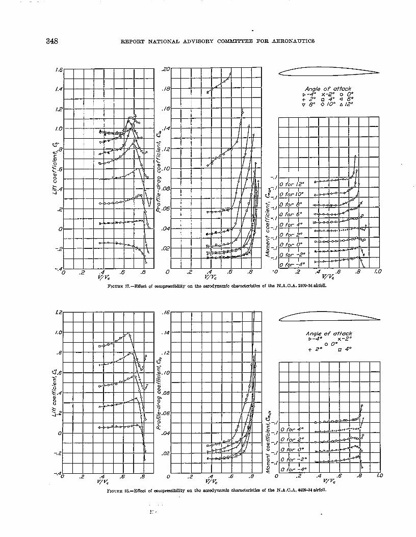
The tmt results are presentad graphically in figures 3to 18. Each figure presents completi data for oneairfoil for the range of angle of attack tested. Eaohcurve shows the variation of one of the coe5cien tawith V/Vc for a given angle of attack. In the pre-sentation of the momentioefficient data the origin ofthe axes for each angle of attack has been raised abovethat for the previous angle of ~ttack, so that themoment curve for any angle may be easily distrn-.@shed.
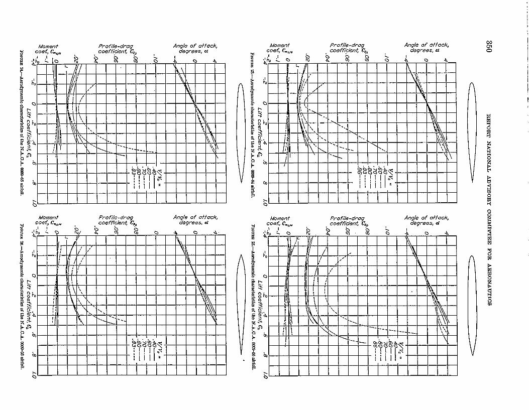
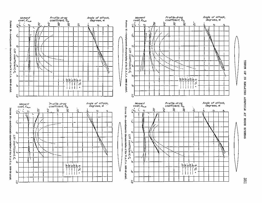
The data presented in figures 3 to 18 were cross-plotted in @gures 19 to 34 to show the aerodynamiccharacteristics of the airfoils in the usual form. Figures35 to 38 show the effect of the important shape vmi-ablea on the aerodynamic characteristics. A compmi-son of the cambered airfoils is given in figures 39 and 40.
PRECISION
The various factors contributing to inaccuracy inthese experiments may, in general, be classified undertwo divisiom. The fit consists of systematic and thesecond, of accidental errors. A detailed discussion ofthe probable systematic errors is given in reference 1.
The.accidental errors are shown by the scattering ofthe points on the curves and by differences betweenoriginal and check tests of the 0009–63 and 0009–66airfoils. Errore in the angle of attick maybe as largeas %0, owing partly to errors in mounting the airfoilsmd partly to dissymmetry of the symmetrical airfoih.The balance and static-plate calibrations made beforemd after the tests checked to within 1.6 percent. Innc-mracies arising from other sources are within +0.006for the lift coeflkient, +0.0006 for the drag coefficient,md +0.002 for the moment coefficient. The errors inthe results of the 0009-66 airfoil may be huger thanthe above-mentioned values because a special correc-tion was applied to these data to account for the largetiymrnetry of this airfoil.
DISCUSSION
The data have been analyzed to show primarily the~ffects of shape changes on airfoil aerodynamic chwwc-zristics at high speeds in order to provide information

Angle of attockx-2° o 0°+ 2° n 4°
TESTS OF 16 RELATED AIRFOILS AT HIGH SPEEDS 343
.8 .12
.6 ./0
0°*.
d.4 $.08*.~ +
k:G 0, $
$.2al
:.-. /
8 .;_. ,*,.40
g _.,
:--f
-.2$
$
-.40.2 .4 .6 .8 0 .2 .4 .6 .8 1.0
FI13WEE%—Effwtofcompressiblfkyon the aa’odgnamfochnmot.ainticsofthe NA.O& (033+safrfoil.
v/v=
v/v=
Angle of ottackX-2” o 0°+ 2“ o 4°
FIQIJRE4.-EITwt ofmmpmsslbllkyon the wcdmo obarnc.tuietfuofthe N.A,O_L fQ12-133alrfoll.
Angle of aftodrx -2” 0 o“+2” 04”
FIGURE5.—Effwtofcompresdbllltyon,themrodynamfccbnmoterfstfuofthe N.A.O.A.IMXW3a!rfoil.15111-3&23

.
is”~+ 1 III I I
Profile -drag coef ficlent, C&
Afwnent coefficient, C+.1 .1 .1 .1 .(
‘a. . . . .
Al
$’
b
b
..Q
Momentl coejffkjen~, C.*
0n
II,

TIWH OF 16 RFILATEID AIRFOILS AT HIGH SPEEDS 3451.
Angle of aifackP -4” X -2.80°
0 0.55”+ 2.25° .04°
u*.
&...U& %t
:.-. I:J.-J
.5-1~Q;-.1ou -.1~
-.G--l
$
-.
0 .2 .4 .6 .8 0 .2 .4 .6 .8v/v=
ov/v=
.2 .4 .6 .8 1.0v/vc
FIGURE 9.—Eflwt of com~blllty on tbe fierdgmwnfo@lmraot@rfstIuof the N.&O.A. lX03+J3afrfofL
.6
Angle of attack.4 b -4° ~ -20
00 0°
+ 2“ ❑ 4“~z,9. -.4 %
j.d -.*-
~ J -..-4
.U~ -.
-.2t!ou-.:
-.4 $
0 .2 .6 .8V7K
o .2 .4 .6 .8v/vc v/v.
fiGURE10.-EfIed of comptibflfty on the rumxlmo abarackristicaof tbe N&O.A. @3BCc3afrfoii -
.8 .12
.6 ~.lo Arl@_eJf oft%b x
*-
LS0 0“
.4c.~.m +2°04”
*- c1.8 z
b<Q
“$.2 ~ .06 J-. Iao bu o *- -. I
.$0 +-m ~-.l4 Q L1
2%. ~-.l
-.2 $.020u -./
:
-.4 0 g
O 2 .4 .6 .8 0 2 .4 .6 .8 0 2 .4 .6 .8 I.Ov/n Vp= v/Pz
fif3URElL—Effeclof wIO@wdMlftyon tbe naodgnam[oobamoteristiu of the N.A.O.A.IDW33afrfofL
— ——-.. _.— —.. _
346 REPORT NATIONAL ADVISORY COMbfTPTE E FOR AERONAUTICS
.8
.6
~.4%-.$b$.2
$
$04
-.2
-.4
02 .6 .8Vjv.
L 1 I I I 1 I 1 Io .2
4.6 -8
V;F%
A77$0of atfafa~
o 0°+ 2* a 4“
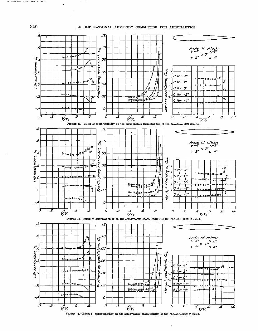
Fmum 12-lMOzt of comwfdbllfty on the wrufmmmfo ~CS Ofthe N. A.OA. MXW3 P&fOfl.
App$ of 0;$
00°+ 2° n 4“
L?%--.I$-. /&
y;
-h~_.J
$
0 .2 .4 .6 ,8 /.0Vflc
FIGURE [email protected] of wmfmsdhflity on the @mO Ohamcteristksof the N.A.O.& WOH!.5F&foil.
.8 .12
.6n & ‘0
-F-kt—lNttttHt+=7-P-lW-H—Hu+
H
W-H++-t llll&llllllllfll II
IEEEi--tq0 -.2 & .8 0 2 .4 .6 .8
v~= Vfl=
<
g)g$ Ofl Ot;cgf
o 0“+ 2“ n 4“
FIQURE14.-Effect of mmpm@bIlftyon the eerc@mernfocfmmckMcs of the N.A.O.A.fW9+%okfoil.
TESTS OF 16 RELATED AJRFOILS AT HIGH SPEEDS 347
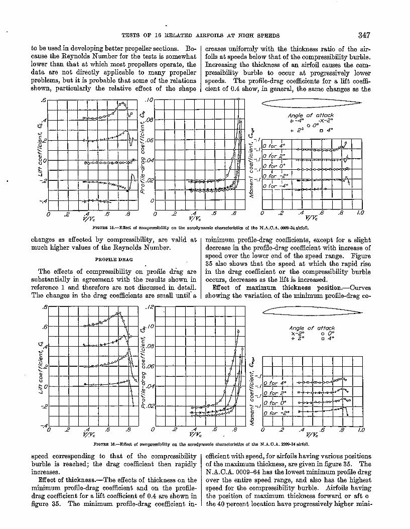
to be used in developing better propeller sections. Be- creases uniformly with the thickness ratio of the air-cause the Reynolds Number for the teats k somewhat foils at speeds below that of the compressibility burble.lower than that at which most propellers operata, the hcreasing the thic.lamss of em airfoil causes the com-data are not directly applicable to many propeller preasibility burble to occur at progressively lowerproblems, but it is probable that some of the relations speeds. The proiile-drag coefficients for a lift coeffi-shown, particularly the relative effect of the shape cient of 0.4 show, in general, the same changes as the
~QUEE 16.—Effectof comprmfbility on tbe aerodyrdunfoclkuncterktlcaof the N.&O.A. CKIXX+IMoD.
changes as affected by compressibility, are valid at minimum profile-drag coefficients, except for a slightmuch higher values of the Reynolds Number. decrease in the profile-drag coefficient with increase of
PROFILE DRAG
The effects of compressibility on proii.le dr-ag aresubstantially in agreement with the results shown inreference 1 and therefore are not discussed in detail.The changes in the drag coefficients are small until’ a
speed over the lower end of the speed range. Figure35 also shows that the speed at which the rapid risein the drag coefficient or the compressibility burbleoccurs, decreases as the lift is increased.
Effect of maximum thickness position.-Curve9showing the variation of the minimum profile-drag co-
Angle of attcxk~-zo o 0°+ 2° II4°
C?*.~ -.1..$-.1QJ0-. /u%--/&.
40 2 .4 .6 .8 /.0
v/K
~amm 16.—Eff0Sof mmprcssfbilityon the aeiw.iymmniooharaotwktk of the N.A.O.A.fiai%31aIi%ll.
speed corresponding to that of the compressibilityburble is reached; the drag coefficient then rapidlyincreases.
lMect of thickness.-The effects of thickness on theminimum profile-drag coefficient and on the proiile-drag coefficient for a lift coefficient of 0.4 are shown infigure 35. The minimum proiile-drag coefficient in-
efficient with speed, for airfoils having various positionsof the maximum thiclmess, axe given in @ure 35. TheN.A.C.A. 0009-04 has the lowest minimum profile dr8g
over the entire speed range, and also has the highestspeed for the comprwaibility burble. Airfoils havingthe position of mtium thiclmess forward or aft othe 40 percent location have progressively higher mini-
348 ~POItT NATIOh-AL ADV160RY COMMITTEE FOR AEROh-AUTICS
1.6
1.4
12
1.0
&
<“8&u
~.6alou
.s .44
-2
0
-.2
-.40 .2 .6 .8
v+=
20
.18
./6
./4.j
~.
5.12g..
;.10
bo~ .~al:k
~.06
.04
.02
0 .2 .6 .8V%c
Angle of attack9-4” x-2° o 0°+2 °a40a60V 8° Q 10” A 12°
J
$-./ IP I& 0 for 4° I r I I
+-*+1
~_, 0 for 2°-. ,WI~ .
alo- &
$_.,O fb ~“ I I
_., O for -2°n-- ~
w0 fQr -4”
* -
-o 2 .4 .6 ,8 1.0Vfi
FIcm3E 17.—Effectofmmmedilftg on the aemxlgnmniaohemc&Mcs oftheN.A.O.A.z4W-34aIr[oIf.
.16
. /4
.12&~.cu 10~.kal$.080!Q&& .06*o&
.04
.0.2
0 .2 .4 J5 .8v/vc
Angle of az?ackP-4” x-2°
o 0“i-2° n 4“
.2 .4 .6 .8 1.0v/vc
FIGCEE l&–Effect 0[ mm~~ On tb tie chnmddstks oftb N.A.C.A. 44W alrfoll.

Moment Pro fik-drag Angle of affack, Moment Profile-drag Angle of affack,
M coef, C.d coeffickn~ C=o degrees, a w Coef, C.OB caeffkien~ (& degrees, d
Moment Profile-drag Anqk of affack,coef, C.,m coefficient CDO dqrees, a
I
Moment Profile-drag Angle of of fock,coef, Cm& coeffitin~ C{O degrees, a
I
Moment Prof;le-dreg Angle of ofiock, Moment Profile-drag Angle of of fock, w
!7 coef, C.& coeffiden~ C=O degrees, a coefr Cm,&M . coefficisn~ C?O degrees, a %
Moment Profile-drag Angle of ai%’ock,coefJCvOfl , coefffdenti C=o degrees, d
I I I I I I I I I
Lib”.#?ll”A A i
f!&E VTwFFFHg> I I I I I I I I I
Q I
t t I I 1 I I I
I 1
Moment Profile-dreg Angle of otfack,coeffkbn~ C..Ocoet, C.& . . . degrees, d
Moment %ofile-drug Angle of oitock,coef, C.oB . coe ffiaent, C?e degrees, d
.!
A
&
c1
k!
‘k
I
b)
b
>0
Moment Profile-drug Angle of attock,coef, C.Oh . coeffia~n~ C?O .. degrees, d

—.
352 REPORT NATIONAL ADVISORY
mum profile drags and earlier compressibility burbles.Prcdile-drag coefficient curves for a lift coefficient of
0.4 are also shown in figure 35. Differences in theproiiledrag coefficient between the 20, 30, and 40 per-cent locations are very small at the lower speeds. Air-foils having their maximum thicknesses located at 50and 60 percent of the chord have the highest drag forspeeds up to approximately 65 percent of the speed ofsound. At higher speeds the airfoil having the farthmtforward location of the maximum thickness becomesthe poorest, due to the earlier compressibility burble.Considering the speed range as a whole, the 40 percantposition seems to be the optimum.
Effect of leading-edge radius.-Figure 35 shows thatthe effects of changes in the leading-edge radius onminimum profile drag are negligible except for very
<- 4
&% Q-<QJ oO?*Z
? -4
.06M55
$ ~-1.03.04* .Q~.~
t?u U.02
To~ J
R::-.4 -.2 0 .2 ..4 .6 .8 /.0
Lift coefficfen~ C=
FIGURE8L—AerIYiYnamiOckacMMiu ofthe N.A.O.A. OUW-.34dIfO~
large values of the leadingdge radius. Airfoils hav-ing variations of the leadingdge radius from a sharpleading edge to the normal leading-edge radius havepractically the same minimum profile drag over theentire speed range. An increase of the leading-edgeradius to three times the normal value causes a rela-tively large increase in drag at the lower speeds, aswell as an earlier compressibility burble. .
With increase in lift, at lower speeds, the airfoilhaving a sharp leading edge has the highest proiile dragdue to the rapid drag increase with angle of attack.As the speed is increased the drag of the N.A.C.A.0009–93 becomes greater, because of its earlier com-pressibility burble. The 0009–33 has the lowest proiiledrag. The quarter normal leading+dge radius istherefore the optimum value for the range of angle ofattack tested.
COMMLT!CEE FOR AERONAUTICS
Examination of the effects of variations of the lend-ing-edge radius for airfoils hav@ their maximumthiclmes-s located at 50 percent of the chord shows wslight increase in the minimum profde drag withincrease of the leading+dge radius. At higher liftcoefficients, there is a very laxge drag increase for thesharp leading edge. The airfoils having the leading-edge dmignations 3 and 6 show small ddlerences.
Lift coefficient C’
FI13UEE3Z-Aerodmmmh obnobxktlcs Ofthe N.A.O.A.ZK&34alrfoU.
IJFr
The lift coefficients for symmetrical airfoils in theusual working range can be expressed in the followingmanner:
C.= ~~a
where ‘CL tie lift~me slope) depends on tl;e shape=(
of the airfoil and the flow parameters. For speedsbelow that of the compreasibi.lit.y burble it has beenshown theoretically in references 4 and 5 that, as ntirst approximation, the effect of compressibility on
‘C’ with the factorlift is to increase ~J% 7.32“
Thisfactor has been substantiated experimentally forspeeds below that at which the compressibility burble

— !2

.. —.—. —.—— ..- — A-.
354 RDPORT NATIONAL ADVTSORY COMMITTEE 170R AERONAUTICS
I I # I I t 1 [
Minimum profile drag Profile dreg fo; CL= 0.4.12 I I
I ,12Vor\ “ofion wi fh thickness
I
R. A. C.A. 0012 -63..J N.A. C.A. OO12-63.-.08 I
/
.08
N. A.C.A. I
~. --0009-63.- I N. A.C. A.
/ //
0009-63—
.04I I
.04
/ Ij _ IUA.C.A. _ _ _ _ __ _ — ~ / -- .-IV.A.C. A. _/> ,0006-63 0006-63
$ 0 0 d’.
:al
~.G I t
Voriofion wifh position of znoximum fhickne Ss%
5.08 I I I , . N. A.C. A. — .08$I ‘- ‘N. A.C.A. -. ‘0009-64Q) N. A.C.A. 0009-62 -- u
0009-63 112
0
bQ.~ / -’]
~-A.c-A. flr+m >- I ~/1 I t ! I r./ N.A.C.A. I
ki
N. A. C.A.0009-t6 . 9 ,zQ. I I = i I “W.CWW-63 I %
to ‘“.. < “.
t 1VoriOfbn 1wiN7 lea ding- edge rud;us
.08 F+ t t ! I f- ;-IV. A.C.A. _i I
I%A.C.A. 0009 -03--- ‘hi. A.c. A.0009-631 , i 8 /
N. A.C.A. 0009 -93-,.04 , i I , t
N.A. C.A. 0009-03.,
I
o .2 .4 .6 -8 1.0 0 .2 .4 .6 .8v/&
/. ov/q
0$
.08
.04
n
Fmm W.-Effect C4compmsdbffftyon proflk drag.
.24
.20 A/ \-‘-N. A.C.A. _
OCW6-63
.16 I
dci.
dd // 7
.12 -- --N. A.C.A. _/ /
\ ‘
OLW9-63e ~
1 I
.08--- ‘-IV. A.C.A. _
0012-63
.04
o .2 .4 .6 .8 1.0 1.2v/~
.24
.20
.16
d C=a /
.12N. A.C. A0009-63 ---w * <N. A. C.A.’---* — -
.080009-64 N. A.C.A.
0~9-65
1 , # 10 .2 .4 .8 1.0 i..?
Vj$q.—~13CRE 33.-El7ectofmmpmsibflftyonUfbcmrmdop Varfntfonwftbtbicknem. FKIUEE 37.-Effeat of mmpresslbflf on llfkarve sfopo. Varlatlonwith @t[on
ofmaznom thhknms.

TESTS OF 16 RELATED AIRFOILS AT HIGH SP1313DS 355
Considering first the airfoils having the mtiumthickness located at 30 percent of the chord, it isapparent that the sharp leading edge is definitely bad.Variations of the leading-edge radius, provided thatthe leading edge is rounded, have apparently negligible
effect on ~— at lower speeds, in agreement with the
results of reference 2. It is to be noted that the blunt-nosed airfoil, the N. A.C.A. 0009–93, shows a very
dCL dCLrapid rise in ~ at high speeds. This rapid rise in ~
is also shown by the 0009-62 airfoil, which has itsmaximum thickness well forward. It should also benoted that the compressibility burble tends to occurprogressively at lower speeds as the leading-edgeradius is increased.
Similimity of the eflects of increasing leading-edgeradius to the effeciw of increasing thickness n@ht have
trend of the effects of camber particularly at l@hspeeds, a few airfoils having certain camber variationsand one of the best thicknew forms have been tested.
Selection of thiokness form.—The choice of the bestform for the thickness distribution was made prin-cipally on the basis of low drag and late compressibilityburble. Within the lift-coefficient range investigated,the tests of symmetrical airfoils indicate that, for anairfoil of medium thickmss, the maximum thicknessshould be located at 40 percent of the chord aft of theleading edge and the leading-dge radius should be one-quarter of the normal value. Thus, the 34-thicknessdistribution would seem to be the beat. The N.A.C.A.0009-34 and three cambered airfoils having this thick-ness distribution were therefore built and tested. Acomparison of the N.A.C.A. 0009+4 and N.A.C.A.0009-34 airfoils (figs. 23 and 31) shows that, except forthe elightiy earlier compressibility burble of the
.24I I I
k40ximum thickness 0.3 cI
Moximum ihickness 0.5c.from leading edge from leading edge
.20 -
I ~--- .: N. A.C. A.
I
0009-93
.16 ; N.A.C.A. _,
h 1 0 “
00Q9-35MA. C.A. 0009 -33,,
~zldd
N. A.C. A. 0009 -63,, ,) 1
.12 - IAL ‘- “:-N.A.C.Ay “ / 0009-65
- // /
/
.08 . 14.A. C.A.--Z ~ <0009-05
.04
0 .2 .4 .6 .8 1.0 0 .2 .4 .6 .8 1.0 1.2v/K v/~
FmtmE &%-Effmtofmm-llltg on IMt+m’veSJOW Variationwith kading+ige mdhm.
been expected because of the higher induced velocitiesover the forward portion of the airfoil caused by suchform changes. Results of the tasts of airfoils withvarious leading-edge radii ha~~ their mtiumthickness located at 50 percent of the chord are insubstantial agreement with the results obtained fromthe tests with the airfoils having their mtium thicli-ness located at 30 percent of the chord, except that thecompressibility burble shown by the airfoil having thenormal leading-edge radius occurs at the l@her speed.
TJHTS OF CAMBERED AIRFOIIS
A detailed study of camber variations has not’beenattempted as part of this investigation. However, inorder to study the application of the data obtainedfrom the symmetrical airfoil tests as well as to devalop,if possible, by means of a few tests, a more efficientpractical propeller section and to indicate the general
N. A.C.A. 0009–34 airfoil, there is practically nodifference in the minimum proiile drag of these airfoils.At moderate lift coefficients the profile drag of theN.A.C.A. 0009–34 decreases slightly with increasingspeed, whereas the proiile drag of the N.A.C.A.0009-64 increases. Because of thie difference, whichmay be attributed to the more gradual compressibilityburble of the N.A.C.A. 0009-64, the N.A.C.A. 0009-34has a lower proiile drag over part of the speed range.As at minimum drag, however, the N. A.C.A. 0009–34hss the earlier compressibility burble. From thiscomparison it is apparent that the general superiorityof either of these airfoils is difficult to establish. Thiscomparison shows, however, that the shift of themaximum ordinate horn the normal to the 40 percentlocation causea much greater improvement than can beobtained from small changes in the leading-edge radius.Future tests to study camber effects should probably

TESTS OF 16 RELATED AJRFOIM AT HIGH SPDEIDS 357
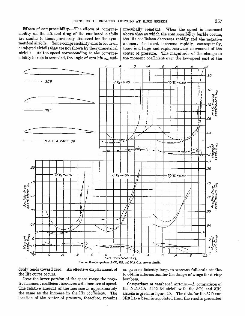
IMectsof compressibility,-The effects of compres- practically constant. men tie speed is hcreased
sibility on the lift and drag of the cambered airfoils nbov~ that at which the compressibility burble occurs,are similar to those previously discussed for the sym- the lift coefficient decreases rapidly and the negativemetrical airfoils. Some comprmsibility effects occur on moment coefficient increasea rapidly; consequently,cambered airfoils that are not shown by the symmetrical there is a large and rapid rearwaxd movement of theairfoils. As the speed corresponding to the compres- center of premure. The magnitude of the change insibility burble is exceeded, the angle of zero lift a% sud- the moment coefficient over the low-speed part of the
------- 9C9
—-— 3R9
N.A. C. A. 2409-34
denly tends toward zero. An effective displacement ofthe lift curve occurs.
Over the lower portion of the speed range the nega-tive moment coefficient increases with increase of speed.The relative amount of the increase is approximatelythe same as the increaae in the lift coefficient. Thelocation of the center of pressure, therefore, remains
I I ~\ I I I I I I 1==1 I.4 .8 .4 0 .4 .8
J-.2 u----- - 1.2
-.:Z’ 1 1 I I I I I I
o .4 .8 -.4
FIWJEE 40.-(Xmpari?an of309, 3E9, and NA.O.A. 24W31rdrfofls.
range is suiliciently large to warrant full-scale studiesto obtain information for the design of wings for divingbombem.
Comparison of cambered airfoils,-A comparison ofthe N.A.C.A. 2409-34 airfoil with the 3C9 and 3R9airfoilsisgiven in figure 40. The data for the 3C9 and3R9 have been interpolated from the results presented
.— ..—. ..— -
COMMITTEE FOR ADRONAU’PICS358 RDPORT NATIONAL ADVISORY
in reference 1. At the lower speeds the N.A.C.A.2409-34 has the lowest minimum drag, the lowestmaximum lift, and therefore the smallest useful angular
. range. As the speed is increased above sii-tenths ofthe speed of sound the N.A.CA. 2409-34 airfoil becomessuperior to both the 3C9 and the 3R9 airfoils, becauseof the larger compressibility effect on the C and R air-foils.
It is probable that the low~eed mtium lift of theNL.C.A. 2409-34 could be increased by increasing thelending-edge radius. Because the effect of the leading-edge radius on profile drag is small, it would seem thatthe 2409-04 airfoil section might ba better for applica-tions requiring n section to operate over a considerablerange of the lift coefficient. In the development ofcambered airfoils, of which the three tested form apreliminmy step, the effects of shape variations on themaximum lift will be more thoroughly investigated,particularly at the lower speeds.
CONCLUSIONS
The principal factors tiecting the choice of propellersections are low drag at low and moderate lift coeffi-cients and a late compressibility burble; that is, lowdrags at high speeds. Considering these factors, thesere.dts indicate:
1. The airfoil thickness should be small.2. The best position for the m&nmm thickness is
approximately 40 percent of the chord aft of the lea~~
3. The optimum vrdues of the lewling~dge radius liebetween 0.22 percent and 0.89 percent of the chord forairfoils of 9 percent thiclmess.
4. At high speeds the N.A.C.A. 2409-34 airfoil issuperior to the commonly used propeller sections. Theresults indicate that some further improvement may boexpected.
LANGLEY MEMORLU AERONAUTICAL LABORATORY,
NATIONAL ADVISORY COIJMI~EE FOR AERONAUTICS,
LANGLEY FIELD, VA., April 28, 19S4.
REFERENCES
1. Stack, John: The N. AC.A. High-Speed Wind Tunnel andTests of Six Propeller Sections. T.R. No. 403, N. A. C.A.,1933.
2. Jacobs, Eastman N., Ward, Kenneth E., and PinkertonjRobert M.: The Charactetilm of 78 Related AfrfoilSections from Teats in the Variable-Density Wind Tunrml.TX. No. 460, N. A. C.A., 1933.
3. Jacobs, Eastman N., and Abbott, Ira H.: The N. A,C.A.Variabl&Density Wind Tunnel. T.R. No. 416, N. A. C.A.,1932.
4. Ackemt, J.: ~er Luftkr&fte bei seh gromen @schwindi-gkeiten insbesondere bei ebenen %rtimungen. HelvetioaPhysics Acts, VOL I, lk3CiCdUS Quintus, 1928, pp. 301-322.
5. Glauert. H.: The Effect of Commemibfitv on the Lift of rinedge. Aero;oil. R. & M. No. 1135, British A.-R.C., 1928.
TABLE I
ORDINATES OF lfRFOIZS
ma-m MB-m MIJ-?s XQ2-35
)Lam.0114.0166.O?m
%%.0341.Wm
:&%!.0S3
:%$. Olm. Olw.CmN
.mz2
)
7Uwa-a
) oL02L2 am.m74 .m.5z.0340 . olm.m70 .0144.U3%9.ols4.W26 .0255.0S9 .fG13.Of@l .mm.Ws .043%.0W3 .0160.m64 .Ofm.oz8 .0393.fIm .0315.0111 .Olm.M31 .Olm.m .mT
Im2-m
o1.Ol!u 0.0144.0!236 .Olm.030!4 .M71.042s .ml.0476 .Ca7.M41 .04m.M7’9 .M33.mm .W.W .M39.M41 .OW.0u2 .03W.0331 .02?8.m7a J3&.014s.M31 .OW.mu .mm To
LOlm a 0133: &l& .0177
.aEa :8$%
.Cm8 .0227
.Cc85 .M23
.0397 .Cm!3
.0437 .Om
.0f60 .0440
.Om .W.m
.mm .0fz3
.0s.9 .0395X&J f333
.m77 .Olm
.Wn .m
Zma-34 !M?J-34 44M-34
%’f!&Km-a
)1 01s9.M37. a317. m74.0410.0144.04m.0441.0415. m74
:%2. Om.m.M5i.Om
Km-3
I%E Lower
)
11mm”mmoam.Ozm :$%:8%.M78 .0245 .0a3
.ml .W9:%3.03m .fmc.0376 .fu!?5 .042Q.0U2 :~m .~.W.W .WM :04m.04m.03m.0354N-& .02m.Oi?-9
.om .Gml.oms .0111 .0111.0149 .ml .ml.m .m .m
o0.0125 Lmm.01=:%% .0181.07m .0214. 15XJ .Ozm. LYm .M71.2033 .0!M9.3X0 .mia.40xl .Ww.EOxl .0r70
:%% :R%.Xml . OEM
. M74:= . mfl
LOXO .MM
-RCE3m–.0373–. 0B4-. Olw-. Olzz–. 0147–. Olst–. m–. mm–. Ore-5-.0249-. Cm3–. 0161-. w-. ma–. m
-: M70–.olm–. 0137–. 01F3–. 0183-.0212–. 0Z31–. m47-. 02bo–. w–. frzzl–. Ols$-. ola7–. mm–. w-. CKm
-: w-. m-. mm-. mm-, mmy&
-. Wo-. mm-, mfa–, m43-. lKQ6-, mm-. m18-, m14-. m
. ....0.0117. Olm. 02s1.m134
xi?.W&2
%%. mlo
%%.023S. Olss.0102.mm
--t—l—Iadfng+dgeradfus--- .mm
t
.015s .mm
-—
0
.Cm?3
—..
I+
.m arm
oit
.m .m .CIl?3
o t
.rrm .m .M2a .mn .mz
slorJ9=-
andofchord..-_. 0 qlo w ‘2/10I

TESm OF 16 RELATED AIRFOILS AT HIGH SPEEDS
TABLE II
COEFFICIENTS FOR FORM EQUATIONS
BneIoekfoUf- 1 Cceflidentsforqu8tIon (I) I Cc8fi3dentsforeqnetIon(2) I
Ddgm no. Q
~ . . . . . . . . . . . . . . . . . . . . . . . . . . . . . . . . . . . . . . . . . . . . . . . . . . 0.2.WKO~ . . . . . . . . . . . . . . . . . . . . . . . . . . . . . . . . . . . . . . . . . . . . . . . . . . .2WXU~-------------------------------------------------- .m~-------------------------------------------------- .X@3m
.mmmE::::::::::::::::::::::::::::::::::::::::::::::::: .m~ . . . ..- . . . ..- . . . . . . . . . ..- . . . . . . . ------------------ .148450
.. . . . . . . . . . . . . . . ------------ ---------------------- .514248~... . . . . . . . . . . . . . . . . . . . . . . . . . . . . . . . . . . . . . . . . . . . . . . .mww . . . . . . . . . . . . . . . . . . . . . . . . . . . . . . . . . . . . . . . . . . . . . . . . . . . lW
------------------ ---------------------------- ---- . 1484.M
41
a 21S337–. W6U32–. 24&W–. 310275–. ‘mm
.8!mW
.412103-.840116
.477am
.a3B51
. lfQ233
al
–2 Q31w–. 643310
. 17m34
. 3417w
. 1402XI-2 W!xO-L ~10
L 1101OI–. m–. IE31.W–. 66SIWT
m &
:*? O.wmm.miml
–.2W17 .W2Jm–.32182u .m–.akw .m28176U0 .-
.m-i%iR .m
.m–:%% .CBEm3
.!zS!z03 .m
d,
Im
:%%. 4oLwXil.m.’mam.Z341m.234am.46YXn.46W31. 31m
d,
–u (Mm–. m–. 233333–. &34COl–L 662S3)–.@8s71–.W671–.Ws371–.684cml~.$84&
1d,
–o.070312–. QKa78–. mzm
1:%%’–.Ws78–. m378-. C?m78
.2mm
–: %%’1
359
GOl<l&24