REPORT DOCUMENTATION PAGE · REPORT DOCUMENTATION PAGE Form Approved ... ( AAS3P-11) and...
154
REPORT DOCUMENTATION PAGE Form Approved OMB No. 0704-0188 The public reporting burden for this collection of information is estimated to average 1 hour per response, including the time for reviewing instructions, searching existing data sources, gathering and maintaining the data needed, and completing and reviewing the collection of information. Send comments regarding this burden estimate or any other aspect of this collection of information, including suggestions for reducing this burden, to Department of Defense, Washington Headquarters Services, Directorate for information on Operations and Reports (0704- 0188), 1215 Jefferson Davis Highway, Suite 1204, Arlington, VA 22202-4302. Respondents should be aware that notwithstanding any other provision of law, no person shall be subject to any penalty for failing to comply with a collection of information if it does not display a currently valid OMB control number. PLEASE DO NOT RETURN YOUR FORM TO THE ABOVE ADDRESS. 1. REPORT DATE (DD-MM-YYYY) 05-12-2014 2. REPORT TYPE Final 3. DATES COVERED (From - To) 4. TITLE AND SUBTITLE Joint Ordnance Test Procedure (JOTP)-011 Safety and Suitability for Service Assessment Testing for Surface and Underwater Launched Munitions 5a. CONTRACT NUMBER 5b. GRANT NUMBER 5c. PROGRAM ELEMENT NUMBER 6. AUTHORS 5d. PROJECT NUMBER 5e. TASK NUMBER 5f. WORK UNIT NUMBER 7. PERFORMING ORGANIZATION NAME(S) AND ADDRESS(ES) Range Infrastructure Division (CSTE-TM) U.S. Army Test and Evaluation Command 2202 Aberdeen Boulevard Aberdeen Proving Ground, MD 21005-5001 8. PERFORMING ORGANIZATION REPORT NUMBER JOTP-011 9. SPONSORING/MONITORING AGENCY NAME(S) AND ADDRESS(ES) Range Infrastructure Division (CSTE-TM) U.S. Army Test and Evaluation Command 2202 Aberdeen Boulevard Aberdeen Proving Ground, MD 21005-5001 10. SPONSOR/MONITOR’S ACRONYM(S) 11. SPONSOR/MONITOR’S REPORT NUMBER(S) Same as item 8 12. DISTRIBUTION/AVAILABILITY STATEMENT Distribution Statement A. Approved for public release; distribution is unlimited. 13. SUPPLEMENTARY NOTES Defense Technical Information Center (DTIC), AD No.: 14. ABSTRACT This Joint Ordnance Test Procedure (JOTP) shall serve as the US Joint Services Safety and Suitability for Service Test Procedures with regards to Surface and Underwater Launched Munitions until which time the Allied Ammunition Safety And Suitability for Service Assessment Test Procedure (AAS3P-11) and Standardization Agreement (STANAG) 4758 are approved by NATO Allied Committee 326 (AC326). Upon approval of the AAS3P, thorough review of this document shall be conducted with the intent to supersede. The munitions covered by the JOTP include missiles, rockets, torpedoes and sea mines launched from ship, submarine, or land based platforms. 15. SUBJECT TERMS joint service HERO safety tests munitions environmental tests ordnance E3 LCEP 16. SECURITY CLASSIFICATION OF: 17. LIMITATION OF ABSTRACT SAR 18. NUMBER OF PAGES 154 19a. NAME OF RESPONSIBLE PERSON a. REPORT B. ABSTRACT C. THIS PAGE Unclassified Unclassified Unclassified 19b. TELEPHONE NUMBER (include area code) Standard Form 298 (Rev. 8-98) Prescribed by ANSI Std. Z39-18
Transcript of REPORT DOCUMENTATION PAGE · REPORT DOCUMENTATION PAGE Form Approved ... ( AAS3P-11) and...
REPORT DOCUMENTATION PAGE Form Approved
OMB No. 0704-0188
The public reporting burden for this collection of information is estimated to average 1 hour per response, including the time for reviewing instructions, searching existing data sources, gathering and maintaining the data needed, and completing and reviewing the collection of information. Send comments regarding this burden estimate or any other aspect of this collection of information, including suggestions for reducing this burden, to Department of Defense, Washington Headquarters Services, Directorate for information on Operations and Reports (0704-0188), 1215 Jefferson Davis Highway, Suite 1204, Arlington, VA 22202-4302. Respondents should be aware that notwithstanding any other provision of law, no person shall be subject to any penalty for failing to comply with a collection of information if it does not display a currently valid OMB control number. PLEASE DO NOT RETURN YOUR FORM TO THE ABOVE ADDRESS.
1. REPORT DATE (DD-MM-YYYY) 05-12-2014
2. REPORT TYPE
Final 3. DATES COVERED (From - To)
4. TITLE AND SUBTITLE Joint Ordnance Test Procedure (JOTP)-011 Safety and Suitability for Service Assessment Testing for Surface and Underwater Launched Munitions
5a. CONTRACT NUMBER
5b. GRANT NUMBER
5c. PROGRAM ELEMENT NUMBER
6. AUTHORS
5d. PROJECT NUMBER
5e. TASK NUMBER
5f. WORK UNIT NUMBER
7. PERFORMING ORGANIZATION NAME(S) AND ADDRESS(ES) Range Infrastructure Division (CSTE-TM) U.S. Army Test and Evaluation Command 2202 Aberdeen Boulevard Aberdeen Proving Ground, MD 21005-5001
8. PERFORMING ORGANIZATION REPORT NUMBER JOTP-011
9. SPONSORING/MONITORING AGENCY NAME(S) AND ADDRESS(ES) Range Infrastructure Division (CSTE-TM) U.S. Army Test and Evaluation Command 2202 Aberdeen Boulevard Aberdeen Proving Ground, MD 21005-5001
10. SPONSOR/MONITOR’S ACRONYM(S)
11. SPONSOR/MONITOR’S REPORT NUMBER(S) Same as item 8
12. DISTRIBUTION/AVAILABILITY STATEMENT Distribution Statement A. Approved for public release; distribution is unlimited. 13. SUPPLEMENTARY NOTES Defense Technical Information Center (DTIC), AD No.: 14. ABSTRACT This Joint Ordnance Test Procedure (JOTP) shall serve as the US Joint Services Safety and Suitability for Service Test Procedures with regards to Surface and Underwater Launched Munitions until which time the Allied Ammunition Safety And Suitability for Service Assessment Test Procedure (AAS3P-11) and Standardization Agreement (STANAG) 4758 are approved by NATO Allied Committee 326 (AC326). Upon approval of the AAS3P, thorough review of this document shall be conducted with the intent to supersede. The munitions covered by the JOTP include missiles, rockets, torpedoes and sea mines launched from ship, submarine, or land based platforms. 15. SUBJECT TERMS joint service HERO safety tests munitions environmental tests ordnance E3 LCEP
16. SECURITY CLASSIFICATION OF: 17. LIMITATION OF ABSTRACT
SAR
18. NUMBER OF PAGES
154
19a. NAME OF RESPONSIBLE PERSON
a. REPORT B. ABSTRACT C. THIS PAGE Unclassified
Unclassified
Unclassified
19b. TELEPHONE NUMBER (include area code)
Standard Form 298 (Rev. 8-98) Prescribed by ANSI Std. Z39-18

(This page is intentionally blank.)
DEPARTMENT OF DEFENSE
JOINT ORDNANCE TEST PROCEDURE (JOTP)-011
SAFETY AND SUITABILITY FOR SERVICE
ASSESSMENT TESTING FOR SURFACE AND UNDERWATER LAUNCHED MUNITIONS
Joint Services Munition Safety Test Working Group

(This page is intentionally blank.)
Joint Ordnance Test Procedure (JOTP)-011 Safety and Suitability for Service Assessment Testing for Surface and Underwater Launched Munitions
DOCUMENT COMPLETION DATE: 5 December 2014
TITLE AND SUBTITLE: Joint Ordnance Test Procedure (JOTP)-011 Safety and Suitability for Service Assessment Testing for Surface and Underwater Launched Munitions
PREPARING ACTIVITY: Range Infrastructure Division (CSTE-TM) U.S. Army Test and Evaluation Command 2202 Aberdeen Boulevard Aberdeen Proving Ground, MD 21005-5001
SPONSORING ACTIVITY: Range Infrastructure Division (CSTE-TM) U.S. Army Test and Evaluation Command 2202 Aberdeen Boulevard Aberdeen Proving Ground, MD 21005-5001
DISTRIBUTION STATEMENT: Distribution Statement A. Approved for public release; distribution is unlimited. ABSTRACT: Joint Ordnance Test Procedure (JOTP)-011 is intended to act as a munition type specific document dealing specifically with the necessary safety testing and assessments for surface and underwater launched munitions to enter service within the North Atlantic Treaty Organization (NATO) community. Two Safety and Suitability for Service (S3) test approaches, analytical and empirical, are presented in this JOTP with the intent that the manager of the test program shall select the more appropriate approach for the munition under test. The munitions covered by the JOTP include missiles, rockets, torpedoes and sea mines launched from ship, submarine, or land based platforms. COORDINATION DRAFT REVIEWED BY: This document was coordinated with the following Standardization Offices: AR, AS, EA, MC, MI, NM, OS, TE, AF-11, and AF-99. In addition, the document was also coordinated with the Joint Weapon Safety Working Group, DODESB, OUSD LW&M, and select subject matter experts within the field of missile and rocket munitions safety testing. ASSIST COORDINATION DATE: 20 August 2014 with a 45-day coordination period. IMPLEMENTATION PLAN: This Joint Ordnance Test Procedure (JOTP) shall serve as the US Joint Services Safety and Suitability for Service Test Procedures with regards to Surface and Underwater Launched Munitions until which time the Allied Ammunition Safety And Suitability for Service Assessment Test Procedure (AAS3P-11) and Standardization Agreement (STANAG) 4758 are approved by NATO Allied Committee 326 (AC326). Upon approval of the AAS3P, thorough review of this document shall be conducted with the intent to supersede. APPROVING AUTHORITY:
Deputy Director, Land Warfare & Munitions Office of the Under Secretary of Defense for Acquisition, Technology and Logistics
DEPARTMENT OF DEFENSE
JOINT ORDNANCE TEST PROCEDURE *Joint Ordnance Test Procedure (JOTP)-011 5 December 2014 DTIC AD No.
SAFETY AND SUITABILITY FOR SERVICE ASSESSMENT TESTING FOR SURFACE AND UNDERWATER LAUNCHED MUNITIONS
Page Paragraph 1. INTRODUCTION ................................................................. 2 2. SCOPE ................................................................................... 3 2.1 Purpose .................................................................................. 3 2.2 Application ............................................................................ 3 2.3 Limitations ............................................................................. 3 3. DEFINITIONS ...................................................................... 3 4. FACILITIES AND INSTRUMENTATION ......................... 5 4.1 Facilities ................................................................................ 5 4.2 Instrumentation Accuracy and Calibration ............................ 5 5. LIFE CYCLE ENVIRONMENTAL PROFILE (LCEP) ...... 5 5.1 LCEP ..................................................................................... 5 5.2 Deviations .............................................................................. 5 6. SAFETY TEST PLANNING ................................................ 6 6.1 Overall Test Objectives ......................................................... 6 6.2 Data Sources .......................................................................... 7 6.3 Test Tailoring ........................................................................ 7 6.4 Munition Packaging .............................................................. 8 6.5 Environmental Test Levels .................................................... 8 6.6 Test Outline ........................................................................... 10 6.7 Test Safety Considerations .................................................... 10 6.8 Test Sample Quantities .......................................................... 10 7. PRE- AND POST-TEST INSPECTIONS ............................ 11 7.1 Initial (Baseline) Inspection .................................................. 12 7.2 Level 1 (Basic) Inspection ..................................................... 12 7.3 Level 2 (Intermediate) Inspection ......................................... 13 7.4 Level 3 (Breakdown Test and Critical Analysis (BTCA)) Inspection .............................................................................. 14 8. S3 TEST PROGRAM OVERVIEW ..................................... 14 8.1 Analytical S3 Test Approach ................................................ 14 8.2 Empirical S3 Test Approach ................................................. 15 8.3 Environmental Tests .............................................................. 16
Approved for public release; distribution unlimited.

JOTP-011 5 December 2014
2
Page 8.4 Operating Tests ...................................................................... 16 8.5 Additional Tests and Assessments ........................................ 17 9. MUNITION SAFETY DATA PACKAGE ........................... 19
APPENDIX A. BACKGROUND/RATIONALE ........................................... A-1 B. TEST PROGRAM FOR SURFACE AND UNDERWATER LAUNCHED MUNITIONS .................................................. B-1 C. ENVIRONMENTAL TEST DESCRIPTIONS ..................... C-1 D. OPERATING TEST DESCRIPTIONS ................................. D-1 E. BREAKDOWN TEST AND CRITICAL ANALYSIS (BTCA) ............................................................. E-1 F. FACILITIES AND INSTRUMENTATION REQUIREMENTS ................................................................ F-1 G. MARGIN OF SAFETY CALCULATIONS FOR PRESSURE VESSELS ......................................................... G-1 H. NON-SEQUENTIAL TESTS/ASSESSMENTS .................. H-1 I. ABBREVIATIONS / REFERENCES / RELATED DOCUMENTS ...................................................................... I-1 1. INTRODUCTION. This Joint Ordnance Test Procedure (JOTP) is aimed at the Safety and Suitability for Service (S3) Assessment Testing for Surface and Underwater Launched Munitions as agreed under Standardization Agreement (STANAG) 4629 and (Allied Ammunition Safety and Suitability for Service Assessment Testing Publication) AAS3P-1. AAS3P-1 provides general discussion of Safety and Suitability for Service Assessment Testing. JOTP-011 is intended to act as a munition type specific document dealing with the necessary safety testing and assessments for surface and underwater launched munitions to enter service within the U.S. Armed Forces community. The launch platforms may be manned or unmanned ground vehicles, ships, or submarines. Two S3 test approaches are presented in this JOTP, analytical and empirical, with the intent that the manager of the test program shall select the more appropriate approach for the munition under test. In assessing S3 it is necessary to assign some form of service life to the item. This is a prediction of the amount of environmental stress the item should be able to withstand without degrading to an unsafe condition based on a risk assessment. These predictions are less likely to be valid the longer an item stays outside of a controlled storage environment as the environment becomes more variable. In-Service Surveillance (ISS) provides the means by which initial service life estimations can be validated or revised to ensure safe and reliable use throughout the required service life. The use of a robust ISS program in conjunction with initial S3 testing of a munition provides a means to assess an item throughout its life. The through life implementation of S3 and ISS techniques is often referred to as Whole Life Assessment (WLA).
JOTP-011 5 December 2014
3
2. SCOPE. This document was developed within the international community and is written with references to both U.S. and NATO test procedures to provide a framework for international procurement and test programs. Table I2-1 (Appendix I, Annex 2) provides cross reference of similar national and international test standards. While each test standard often has unique requirements, the table does not imply the standards are the same or interchangeable. However, international test standards, or test methods, may be substituted for the national test standards referenced in the JOTP providing it can be determined that the international specification is technically equivalent or superior to the referenced methods. 2.1. Purpose. The purpose of this JOTP is to guide personnel involved in the planning and implementation of S3 assessment testing of munitions to enable appropriate evidence to be collected covering the entire life cycle. The objective of the safety test program defined by this JOTP is to provide data to demonstrate that the munition will be “safe for use”, as defined in AAS3P-1, throughout the potential deployment possibilities in U.S. service. 2.2. Application. The guidance provided in this JOTP is applicable to NATO, multi-National collaborative and National acquisition of surface and underwater launched munitions. The munitions covered by the JOTP include missiles, rockets, torpedoes and sea mines launched from ship, submarine, or land based platforms. These platforms are further identified as having remote (unmanned) or manned launch stations. 2.3. Limitations. This JOTP is not intended to be used in the assessment of effectiveness, reliability or performance of a munition unless failure to be reliable or to perform effectively is deemed to represent a direct and immediate safety hazard to the user or other personnel. However, the data may be used in the support of effectiveness, reliability, or performance assessment. This document does not define the ISS or stockpile reliability test requirements; however, the data may be used in the support of planning for these requirements. Refer to STANAG 4675 for further guidance. This document is not intended to address nuclear munitions. 3. DEFINITIONS. Definitions in this JOTP take precedence over those in AAS3P-1, which in turn take precedence over those in AOP-38 until such time as they can be incorporated into AOP-38. Refer to AAS3P-1 for definitions related to Safety and Suitability for Service test procedures. 3.1 Rocket. An unguided projectile to which self-contained propulsive energy is applied during flight.
JOTP-011 5 December 2014
4
3.2 Missile. A guided projectile to which self-contained propulsive energy is applied during flight. 3.3 Torpedo. A self-propelled munition that follows an underwater path and is designed to detonate either on contact with or within close proximity to its target. Note: It may be launched from above or below the water surface. 3.4 Complete Round. A complete fully assembled munition consisting of all components as required for intended use. Note: This may include, for example, live energetics, tactical electronics, safe-and-arm devices, etc. The munition may come factory assembled or may require assembly by service personnel prior to use. In some countries, this is also known as an All Up Round. 3.5 Temperature Conditioning. Exposure of a munition to a thermal environment in preparation for a test event at a specified test temperature. 3.6 Pre-Stress. Exposure of a munition to a sequence of one or more environmental stresses (i.e., temperature, humidity, shock, vibration, etc.) prior to conducting a particular test event. 3.7 Solar Radiation Equivalent (SRE) Temperature. The maximum temperature value experienced by the energetic material (e.g., motor propellant, warhead, fuze) during the solar test. Note: Determination of this value will require exposure of an inert, internally instrumented munition, with similar thermal characteristics to the complete round, to the full solar test requirement defined in MIL-STD-810, Method 505. The SRE temperature should be determined for the packaged and unpackaged state. In the absence of this data, a value of +71 °Celsius (C) should be used for the SRE temperature. 3.8 Temperature Stabilization. Temperature stabilization is achieved when the part of the item considered to have the longest thermal lag is changing no more than 2 °C per hour. Note: Since it may not be practical to monitor the part of a live munition with the longest thermal lag during test without damaging seals, the stabilization time may be determined prior to live munition testing using an inert, internally instrumented munition, with similar thermal characteristics to the complete round. The stabilization time will typically be required for the munition in both the unpackaged and the transport configurations and at the hot and cold temperature extremes. For packaged configurations, stabilization times are dependent upon the dimensions of the container, container dunnage, and the air gap between the munition and container.
JOTP-011 5 December 2014
5
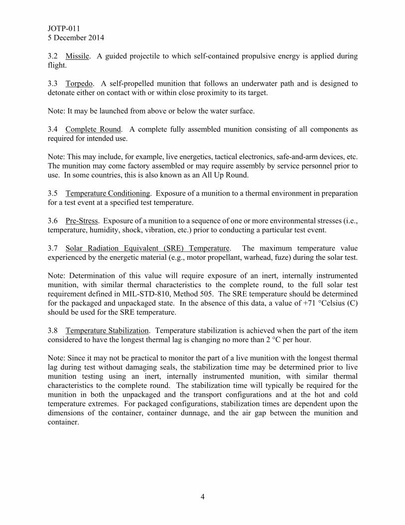
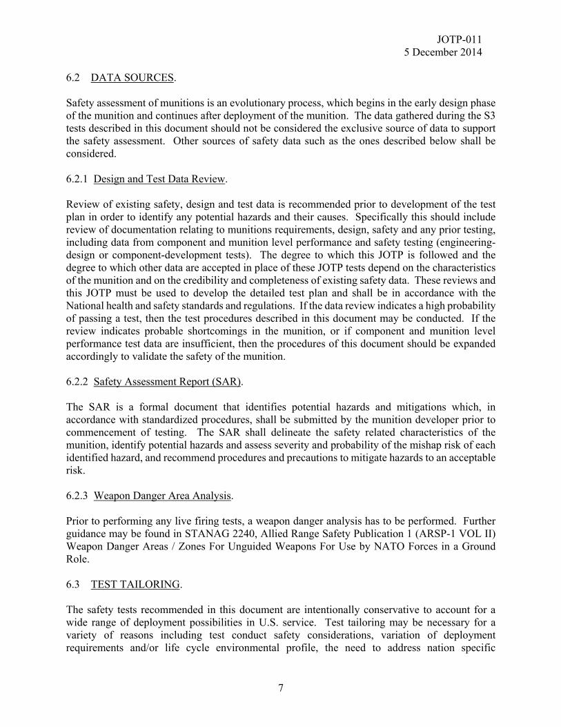
4. FACILITIES AND INSTRUMENTATION. 4.1 Facilities. All test facilities utilized must suit specific test requirements and provide adequate protection for personnel and equipment in accordance with local and national regulations for testing of hazardous material. Note that although it is not necessary for all the facilities to be co-located, consideration should be given to the safe transport of potentially degraded test articles between test facilities. In addition to the requirements provided in Appendix F, Table F-1, test facilities shall be prepared for the handling and possible disposal of explosive items. 4.2 Instrumentation Accuracy and Calibration. The instruments and test equipment used to control or monitor the test parameters shall have an accuracy at least equal to 1/3 the tolerance of the variable to be measured. Recommended tolerances are provided in Appendix F, Table F-2. In the event of conflict between this accuracy and guidelines for accuracy in any one of the test procedures or methods referenced in this document, the more stringent accuracy requirement takes precedence. The instrumentation and test equipment shall be calibrated periodically to laboratory standards whose calibration is traceable to national laboratory standards. The test facility shall maintain the calibration records. 5. LIFE CYCLE ENVIRONMENTAL PROFILE (LCEP). 5.1 LCEP. Surface and underwater launched munitions are likely to encounter the environments shown in Figure 1 throughout the life cycle. Figures 3 and 4 illustrate general test flows associated with these environments. Detailed tests flows are provided in Appendix B of this document as sequential test flowcharts and munition allocation tables. Test guidelines are presented in Appendix C and rationale are provided in Appendix A. An attempt has been made to define test flows such that environmental tests are conducted at representative points in the life cycle. These test flows are based upon the applicable environmental factors for storage, transportation, and deployment selected from Allied Environmental Conditions and Test Publication (AECTP) 100, Annex A along with the generic usage profiles from AECTP 100, Annex E for the land vehicle mounted missile and the sea launched missile. Testing in accordance with this life cycle sequence and combining environments (i.e., vibration with temperature) is required to determine if the interaction (synergistic effect) and/or the sequence in which environments are experienced may result in a safety hazard. If the munition specific LCEP identifies environments or usage profiles significantly in excess of those provided in this document, the test specifications should be adjusted accordingly. 5.2 Deviations. Deviations from these LCEPs contained in this document shall be approved by National S3 Authority(ies) or other appropriate Authorities prior to the start of testing. The rationale used in tailoring shall be documented and retained as part of the Munition Safety Data Package as noted in Annex C of AOP-15.
JOTP-011 5 December 2014
6
Figure 1. Expected environments for surface and underwater launched munitions. 6. SAFETY TEST PLANNING. 6.1 OVERALL TEST OBJECTIVES. The objectives of the safety tests are to provide data to demonstrate that the munition is “safe for use” as defined in AAS3P-1. To achieve this, safety tests must provide data to determine the following: a. Existence and nature of actual and potential munition hazards to personnel and equipment. b. Safety of the munitions throughout the planned LCEP including storage, transport, maintenance, training, operations, firing, and disposal.
Manufacturing Facility
DYNAMIC ENVIRONMENTS
Military Transport
Military Land Transportation Dynamics
Military Air Transportation Dynamics
Military Sea Transportation Dynamics
Tactical Combat Platform
Launch Platform Transport Vibration
Launch Shock
Launch Platform Transport Shock
Unpackaged/Packaged Drop
End Use
ELECTROMAGNETICENVIRONMENTS
Electromagnetic Radiation
Electrostatic Discharge
Lightning
CLIMATIC ENVIRONMENTS
High Temperature Cycle
High Temperature Storage
Low Temperature Storage
Humid Heat
Low Temperature Cycle
Mould Growth
Contamination by Fluids
Rapid Decompression
Solar Radiation
Rain / Watertightness
Sand and Dust
Salt Fog
Thermal Shock
Immersion / Pressurization
Icing
Logistic Transport
Logistic Wheeled Vehicle Dynamics
Logistic Sea Transportation Dynamics
Packaged Transit Drop
Logistic Air Transportation Dynamics
Logistic Rail Transportation Dynamics
JOTP-011 5 December 2014
7
6.2 DATA SOURCES. Safety assessment of munitions is an evolutionary process, which begins in the early design phase of the munition and continues after deployment of the munition. The data gathered during the S3 tests described in this document should not be considered the exclusive source of data to support the safety assessment. Other sources of safety data such as the ones described below shall be considered. 6.2.1 Design and Test Data Review. Review of existing safety, design and test data is recommended prior to development of the test plan in order to identify any potential hazards and their causes. Specifically this should include review of documentation relating to munitions requirements, design, safety and any prior testing, including data from component and munition level performance and safety testing (engineering-design or component-development tests). The degree to which this JOTP is followed and the degree to which other data are accepted in place of these JOTP tests depend on the characteristics of the munition and on the credibility and completeness of existing safety data. These reviews and this JOTP must be used to develop the detailed test plan and shall be in accordance with the National health and safety standards and regulations. If the data review indicates a high probability of passing a test, then the test procedures described in this document may be conducted. If the review indicates probable shortcomings in the munition, or if component and munition level performance test data are insufficient, then the procedures of this document should be expanded accordingly to validate the safety of the munition. 6.2.2 Safety Assessment Report (SAR). The SAR is a formal document that identifies potential hazards and mitigations which, in accordance with standardized procedures, shall be submitted by the munition developer prior to commencement of testing. The SAR shall delineate the safety related characteristics of the munition, identify potential hazards and assess severity and probability of the mishap risk of each identified hazard, and recommend procedures and precautions to mitigate hazards to an acceptable risk. 6.2.3 Weapon Danger Area Analysis. Prior to performing any live firing tests, a weapon danger analysis has to be performed. Further guidance may be found in STANAG 2240, Allied Range Safety Publication 1 (ARSP-1 VOL II) Weapon Danger Areas / Zones For Unguided Weapons For Use by NATO Forces in a Ground Role. 6.3 TEST TAILORING. The safety tests recommended in this document are intentionally conservative to account for a wide range of deployment possibilities in U.S. service. Test tailoring may be necessary for a variety of reasons including test conduct safety considerations, variation of deployment requirements and/or life cycle environmental profile, the need to address nation specific
JOTP-011 5 December 2014
8
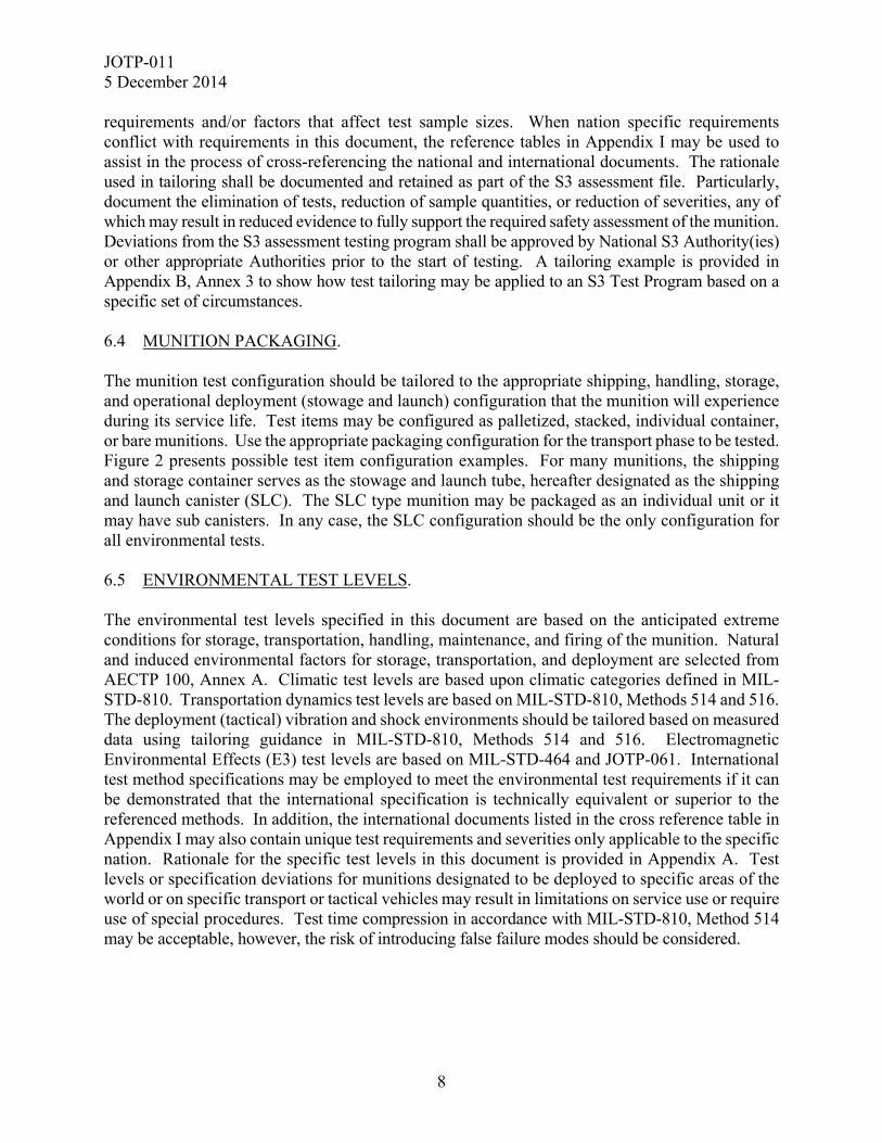
requirements and/or factors that affect test sample sizes. When nation specific requirements conflict with requirements in this document, the reference tables in Appendix I may be used to assist in the process of cross-referencing the national and international documents. The rationale used in tailoring shall be documented and retained as part of the S3 assessment file. Particularly, document the elimination of tests, reduction of sample quantities, or reduction of severities, any of which may result in reduced evidence to fully support the required safety assessment of the munition. Deviations from the S3 assessment testing program shall be approved by National S3 Authority(ies) or other appropriate Authorities prior to the start of testing. A tailoring example is provided in Appendix B, Annex 3 to show how test tailoring may be applied to an S3 Test Program based on a specific set of circumstances. 6.4 MUNITION PACKAGING. The munition test configuration should be tailored to the appropriate shipping, handling, storage, and operational deployment (stowage and launch) configuration that the munition will experience during its service life. Test items may be configured as palletized, stacked, individual container, or bare munitions. Use the appropriate packaging configuration for the transport phase to be tested. Figure 2 presents possible test item configuration examples. For many munitions, the shipping and storage container serves as the stowage and launch tube, hereafter designated as the shipping and launch canister (SLC). The SLC type munition may be packaged as an individual unit or it may have sub canisters. In any case, the SLC configuration should be the only configuration for all environmental tests. 6.5 ENVIRONMENTAL TEST LEVELS. The environmental test levels specified in this document are based on the anticipated extreme conditions for storage, transportation, handling, maintenance, and firing of the munition. Natural and induced environmental factors for storage, transportation, and deployment are selected from AECTP 100, Annex A. Climatic test levels are based upon climatic categories defined in MIL-STD-810. Transportation dynamics test levels are based on MIL-STD-810, Methods 514 and 516. The deployment (tactical) vibration and shock environments should be tailored based on measured data using tailoring guidance in MIL-STD-810, Methods 514 and 516. Electromagnetic Environmental Effects (E3) test levels are based on MIL-STD-464 and JOTP-061. International test method specifications may be employed to meet the environmental test requirements if it can be demonstrated that the international specification is technically equivalent or superior to the referenced methods. In addition, the international documents listed in the cross reference table in Appendix I may also contain unique test requirements and severities only applicable to the specific nation. Rationale for the specific test levels in this document is provided in Appendix A. Test levels or specification deviations for munitions designated to be deployed to specific areas of the world or on specific transport or tactical vehicles may result in limitations on service use or require use of special procedures. Test time compression in accordance with MIL-STD-810, Method 514 may be acceptable, however, the risk of introducing false failure modes should be considered.
JOTP-011 5 December 2014
9
Single Launch Tube
Packaged Munition
Palletized Configuration
Shipping and Launch Canister
Figure 2. Packaging configuration examples.
JOTP-011 5 December 2014
10
6.6 TEST OUTLINE. S3 assessment testing of surface and underwater launched munitions requires a series of sequential environmental tests, operating/firing tests, and non-sequential (stand alone) environmental tests. The test flowcharts and munition allocation tables are shown in Appendix B in this document. These include sequential and combined environmental tests (i.e., vibration with temperature) to determine if the interaction (synergistic effect) and/or the sequence in which environments are experienced may result in a safety hazard. 6.7 TEST SAFETY CONSIDERATIONS. Explosive materials often become less stable with age. This ageing is exacerbated by the presence of increased temperature, humidity and vibration/mechanical stressing. It is therefore necessary to review the projected test sequence and determine whether the sequence, including any temperature conditioning and storage, result in an unacceptable hazard. As a minimum this will require an assessment of explosive material stability with respect to extreme temperature exposure durations. It might be necessary to divide the overall test time (shock and vibration in particular) into smaller portions to prevent heat build-up within the weapon and subsequent unintended energetic reaction. It is essential and mandatory to have a log for each weapon indicating the amount of time that has been spent at extreme temperature for the entire test sequence, including all periods of temperature conditioning. 6.8 TEST SAMPLE QUANTITIES. The test sample quantities are largely dictated by the minimum number of destructive tests (i.e., static firing, dynamic firings, breakdown test and critical analysis (BTCA), pressure vessel structural integrity tests, hazard classification, and insensitive munitions) to provide sufficient evidence of munition safety. Specific rationale for the quantities in each of the destructive test categories is provided in Appendix A. The following general notes should be considered when assessing the test sample quantities required for an S3 test program: a. Materiel having more than one configuration, operating state, or operating platform may require increased test sample quantities. b. Existing safety data may also be reviewed for acceptability with the goal of reducing sample sizes and the number of tests. The degree to which this data can be used depends upon munition characteristics, reliability and completeness of the existing safety data, and the adequacy with which it treats hardware configuration, input stress, potential synergistic effects, types and severity of hazards, and the probability of hazard occurrences. However, tests which may interact with each other in a synergistic fashion (e.g., vibration/shock or vibration/climate) must not be removed from the sequence. c. Additional munitions beyond those recommended in this document may be needed in the test program for baseline purposes and to replace items that become damaged during testing. Also, fully inert munitions may be required for pre-cursor testing (thermal and mechanical) to evaluate and certify test procedures, setups and fixtures. Completely functional inert munitions
JOTP-011 5 December 2014
11
may also be required to perform powered Hazards of Electromagnetic Radiation to Ordnance (HERO) tests. d. Completely functional munitions are only required for test assets designated for the dynamic firing tests. For all other test assets, non-safety critical components (e.g., tactical guidance and control sections) may be removed in order to reduce test cost. Any hardware that is removed should be replaced by mass simulants with thermal, structural, and dynamic characteristics similar to the tactical hardware. e. Tailoring of Test Sample Quantities. The test sample quantities or configuration may be modified provided rationale is approved by the appropriate National S3 Authority(ies) or other appropriate Authorities. For example, the number of dynamically fired test items may be reduced if: (1) Previous firing tests of worst case pre-stressed and temperature conditioned munitions provide the required fuze arming test data. Data from the previous firing tests are required to be provided with the new S3 assessment file. (2) The fuze arming tests are not applicable. For example, specific munition classes may not contain a warhead such as kinetic energy munitions. (3) Firing safety tests of shipping/launch container or canister type munitions must be conducted to prove safe egress from the launch canister at the end of the environmental test sequence. Ripple or rapid firing munitions require at least four dynamic firings (2 hot and 2 cold) to prove first round firing doesn’t affect the second round firing. This number may be reduced to two dynamic firings (1 hot and 1 cold) for single munition launch canisters. If the munition is not canistered and/or safe egress does not need to be demonstrated, then the requirement for dynamic firings can be eliminated from the Analytical test program. f. Tailoring of Reduced BTCA Test Sample Quantities. Reduced BTCA test flow sequences may allow for the redistribution and/or reduction of test assets. This is dependent upon the level of BTCA testing required by the National S3 Authority (ies) or other appropriate Authorities. Upon completion of reduced BTCA testing, the munition may be a complete, ready to use round which can be designated for component testing or dynamic firing. For example, chemical stabilizer depletion tests may only require small slivers (~5 grams) of propellant which can be obtained without extreme damage to the munition. Therefore, these rounds could be used to provide additional test data or to reduce the total sample quantity by replacing the dynamic fire or component test assets. 7. PRE AND POST-TEST EXAMINATION. Perform inspections of the munitions as indicated in the sequential test flowcharts in Appendix B. Inspections are to be conducted in accordance with the inspection levels defined below. Perform the appropriate inspections, checks or disassembly before and after any non-destructive munition S3 test and when test exposure is considered to have affected the test item. Conduct radiographic and/or other non-destructive inspection of the test item to ascertain and document any external and
JOTP-011 5 December 2014
12
internal conditions existing prior to, or resulting from testing. Safety mechanisms and devices shall remain in their safe condition. Non-destructive techniques utilized shall have the capability to accurately assess condition of the safety critical characteristics. 7.1 INITIAL (BASELINE) INSPECTION. An initial inspection should be conducted to verify conformance of the munition to the build standard (see AAS3P-1) and to provide an assessment of the baseline condition for subsequent test inspections. In addition to the Level 1 and Level 2 examinations described in Paragraphs 7.2 and 7.3, initial inspections should include baseline photographs and the items listed below. Deviations from the build standard should be assessed by the appropriate authorities to determine that the asset(s) is satisfactory for the S3 test program. a. Physical characteristics such as weight and all critical dimensions for the munition and packaging. b. Manufacturer, manufacturer’s markings, and lot/batch numbers for the munition and packaging. c. Propellant manufacturer, type, and grain. d. Payload manufacturer, type, and charge weight. e. Materials of construction. f. Packaged configuration and number of rounds per shipping container. 7.2 LEVEL 1 (BASIC) INSPECTION. Level 1 (Basic) consists of visual examination and built in test (BIT). Visually inspect all test items to determine the following: a. Condition of shipping container. (1) Physical damage. (2) State of pressurization, fluids, and seals. (3) State of desiccant and humidity indicators. (4) State of munition retention hardware. (5) State of shock and temperature indicators. (6) Electrical Earthing / Grounding device.
JOTP-011 5 December 2014
13
b. Condition of the munition or subsystem. (1) Physical damage. (2) Indication of seepage, leaks, or exudation. (3) State of indicators. (4) State of seals. (5) State of safe and arming (S&A) devices and fuzes. (6) Check connectors. (7) Condition of exposed cables. (8) BIT checks if appropriate. (9) Inspection of health monitoring unit and data if applicable. 7.3 LEVEL 2 (INTERMEDIATE) INSPECTION. Level 2 (Intermediate) encompasses Level 1, but also consists of radiography and non-destructive examinations (e.g., ultrasonic, tomography, magnaflux, eddy current) of all munitions and pyrotechnic devices. The examination facility should have the capability to conduct radiographic inspection at low temperature extremes or as soon as possible, after removal from a cold conditioning chamber (15 minutes for man portable items and 30 minutes for non-man portable items). Deviation from this should be recorded and accepted by the appropriate authority. Level 2 inspections should determine the following: a. State of S&A devices and fuzes to include testing all accessible squibs with a certified low current circuit tester or squib meter and performing umbilical electrical tests to ensure the munition is safe for handling and continued testing. b. Indications of structural damage. c. Condition of the propulsion unit assembly to check for cracks, voids, slump, liner cracking/detachment, or any other failure modes identified during the preliminary design assessment. This inspection should be conducted at the low operating temperature. d. Condition of the warhead assembly to check for cracks, voids, defective adhesion, exudation, or any other failure modes identified during the preliminary design assessment. This inspection should be conducted at the low operating temperature. e. Movement of internal components.
JOTP-011 5 December 2014
14
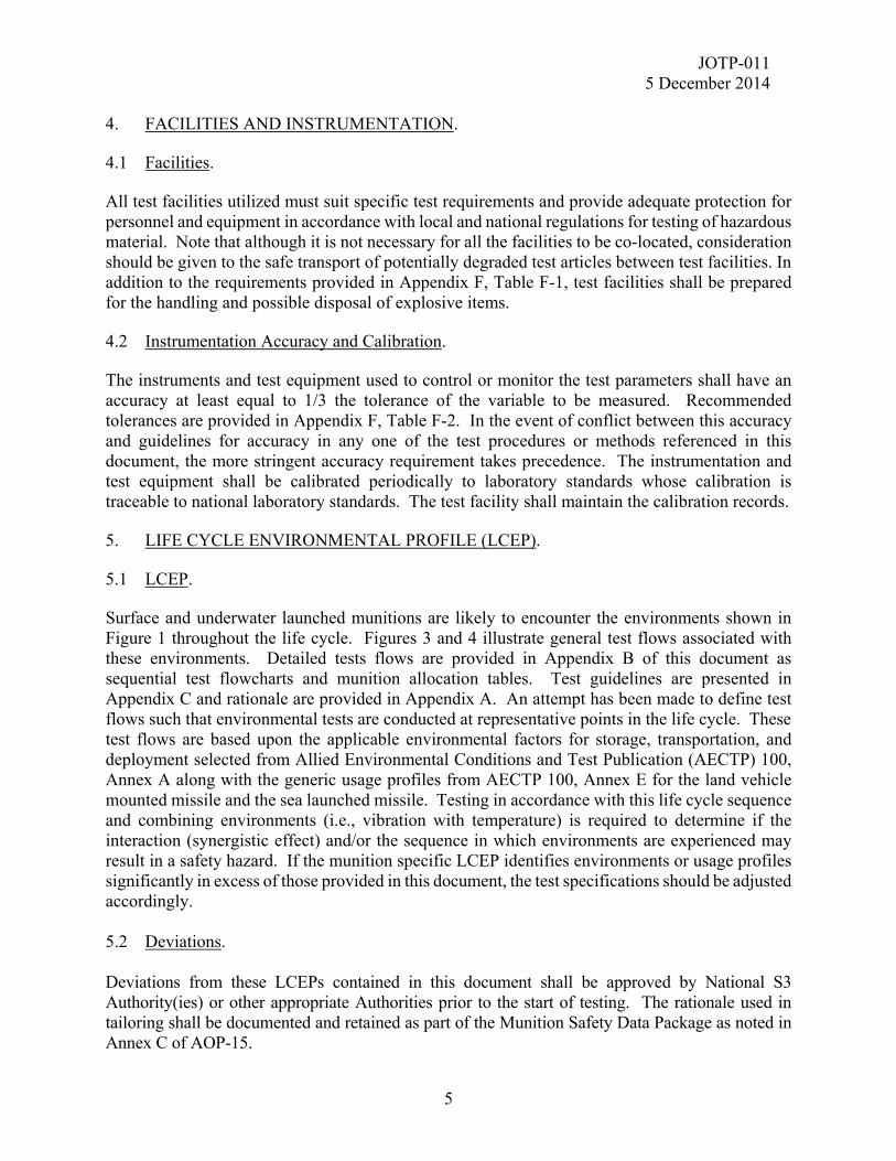
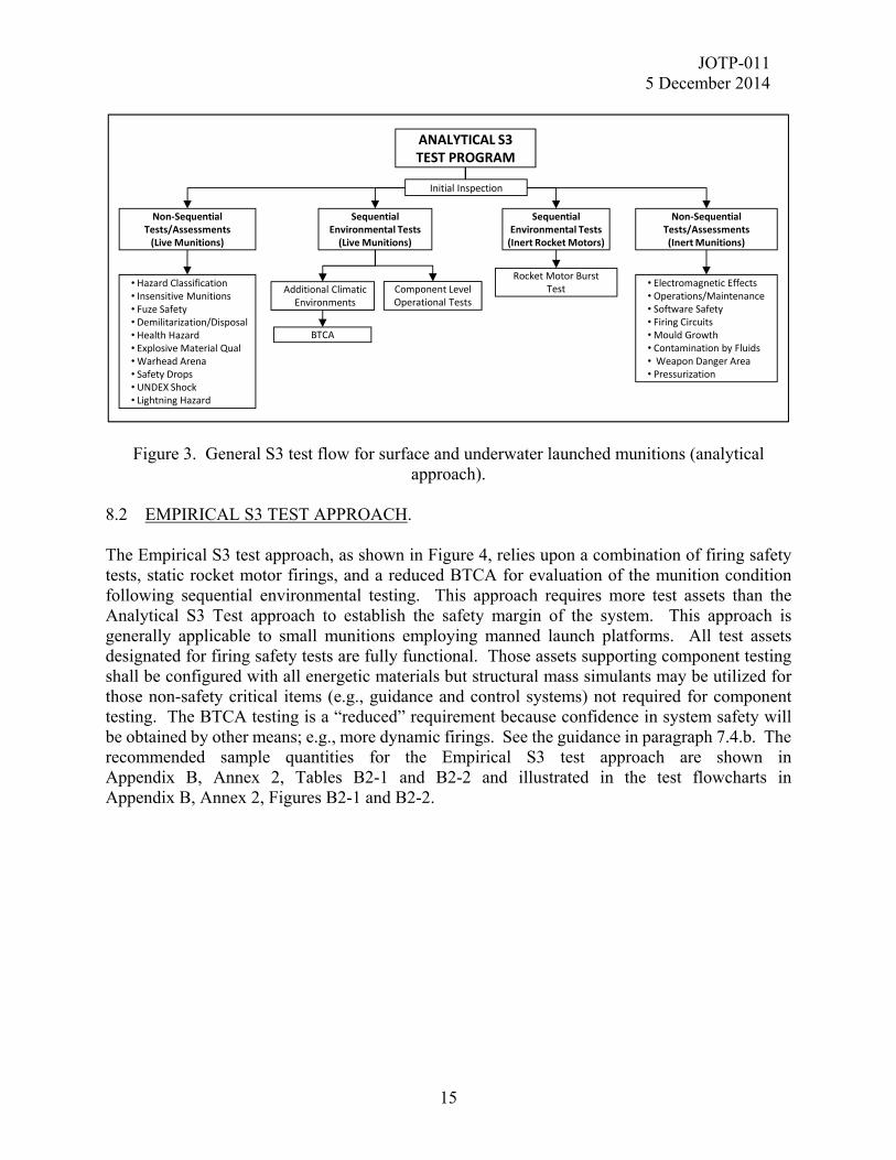
7.4 LEVEL 3 (BREAKDOWN TEST AND CRITICAL ANALYSIS (BTCA)) INSPECTION. a. Level 3 (BTCA) encompasses Level 1 and 2, but also includes disassembly for internal inspection. This is typified by destructive inspection assessing the chemical (composition, hazard properties, etc) and physical (tensile, hardness, etc.) properties of not just the explosive materials, but also of other critical engineering materials contained within the test item. The requirements in Appendix E encompass safety critical and energetic ageing matters. b. Reduced BTCA is permitted in the Empirical Test Flow to eliminate most of the energetic material assessments described in paragraphs E.2.7.2 through E.2.7.6, with the exception that essential energetic material tests are required in accordance with E.2.7.2.b. The selected energetic material tests should be based on an assessment of the energetic material properties required to demonstrate safe transport and launch of the munition. For example, stabilizer concentrations should be measured for all double base propellants. 8. S3 TEST PROGRAM OVERVIEW. Two approaches for S3 Testing, Analytical and Empirical, are presented in Appendix B. While both of these approaches provide satisfactory confidence in the S3 assessment of any munition type, there are inherent benefits in terms of cost and test efficiency that tend to associate the Analytical S3 Test Approach with large, complex munition systems and the Empirical S3 Test Approach with the smaller, less complex munition systems. 8.1 ANALYTICAL S3 TEST APPROACH. The Analytical S3 test approach, as shown in Figure 3, evaluates the munition condition following sequential environmental testing by rocket motor firings, BTCA and component tests. This approach requires fewer test assets than the Empirical S3 approach and is generally applicable to large ship, submarine, and remotely launched land munitions. a. This approach requires the minimum number of assets since it provides the highest level of component level test data for all safety critical components. Note, non-safety critical components (e.g., guidance and control sections) may be removed from the munitions and replaced with structural mass simulants. The recommended sample quantities for the Analytical S3 test approach are shown in Appendix B, Annex 1, Tables B1-1 and B1-2 and illustrated in the test flowcharts in Appendix B, Annex 1, Figures B1-1 and B1-2. b. Firing safety tests are required for munitions designed to be fired from the SLC under the Analytical S3 Test Approach. These firings demonstrate safe egress of environmentally stressed munitions from the launch canister. These test assets may have mass simulants in place of non-safety related components, if flight performance is not a test requirement.
JOTP-011 5 December 2014
15
Figure 3. General S3 test flow for surface and underwater launched munitions (analytical approach).
8.2 EMPIRICAL S3 TEST APPROACH.
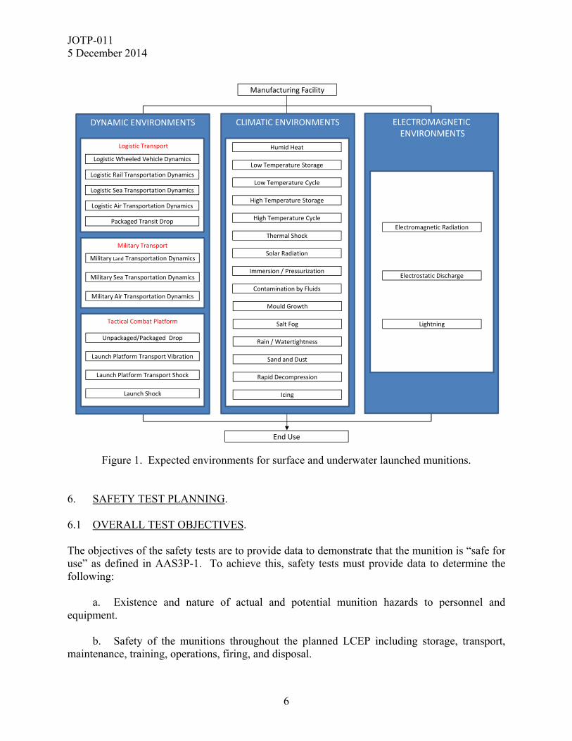
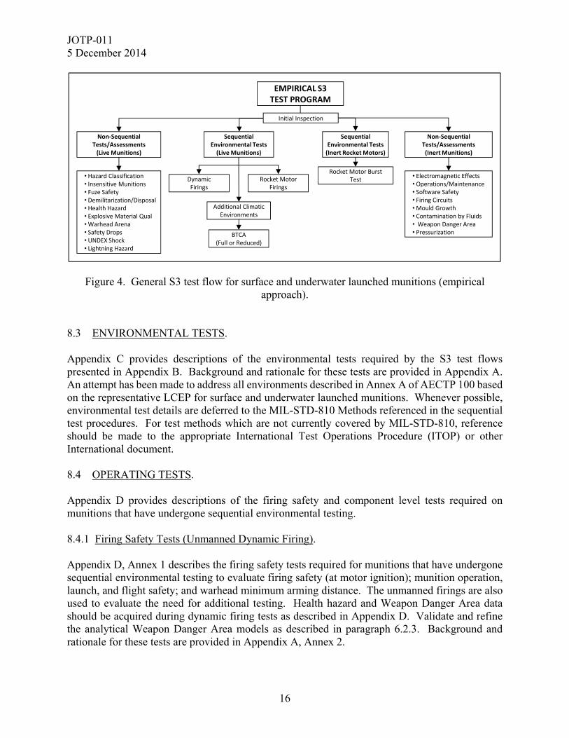
The Empirical S3 test approach, as shown in Figure 4, relies upon a combination of firing safety tests, static rocket motor firings, and a reduced BTCA for evaluation of the munition condition following sequential environmental testing. This approach requires more test assets than the Analytical S3 Test approach to establish the safety margin of the system. This approach is generally applicable to small munitions employing manned launch platforms. All test assets designated for firing safety tests are fully functional. Those assets supporting component testing shall be configured with all energetic materials but structural mass simulants may be utilized for those non-safety critical items (e.g., guidance and control systems) not required for component testing. The BTCA testing is a “reduced” requirement because confidence in system safety will be obtained by other means; e.g., more dynamic firings. See the guidance in paragraph 7.4.b. The recommended sample quantities for the Empirical S3 test approach are shown in Appendix B, Annex 2, Tables B2-1 and B2-2 and illustrated in the test flowcharts in Appendix B, Annex 2, Figures B2-1 and B2-2.
Sequential Environmental Tests (Inert Rocket Motors)
Sequential Environmental Tests(Live Munitions)
Additional Climatic Environments
Component Level Operational Tests
Initial Inspection
ANALYTICAL S3 TEST PROGRAM
Non‐Sequential Tests/Assessments (Live Munitions)
Non‐Sequential Tests/Assessments(Inert Munitions)
• Hazard Classification• Insensitive Munitions• Fuze Safety• Demilitarization/Disposal• Health Hazard• Explosive Material Qual• Warhead Arena• Safety Drops• UNDEX Shock• Lightning Hazard
• Electromagnetic Effects• Operations/Maintenance• Software Safety• Firing Circuits• Mould Growth• Contamination by Fluids• Weapon Danger Area• Pressurization
Rocket Motor Burst Test
BTCA
JOTP-011 5 December 2014
16
Figure 4. General S3 test flow for surface and underwater launched munitions (empirical approach).
8.3 ENVIRONMENTAL TESTS. Appendix C provides descriptions of the environmental tests required by the S3 test flows presented in Appendix B. Background and rationale for these tests are provided in Appendix A. An attempt has been made to address all environments described in Annex A of AECTP 100 based on the representative LCEP for surface and underwater launched munitions. Whenever possible, environmental test details are deferred to the MIL-STD-810 Methods referenced in the sequential test procedures. For test methods which are not currently covered by MIL-STD-810, reference should be made to the appropriate International Test Operations Procedure (ITOP) or other International document. 8.4 OPERATING TESTS. Appendix D provides descriptions of the firing safety and component level tests required on munitions that have undergone sequential environmental testing. 8.4.1 Firing Safety Tests (Unmanned Dynamic Firing). Appendix D, Annex 1 describes the firing safety tests required for munitions that have undergone sequential environmental testing to evaluate firing safety (at motor ignition); munition operation, launch, and flight safety; and warhead minimum arming distance. The unmanned firings are also used to evaluate the need for additional testing. Health hazard and Weapon Danger Area data should be acquired during dynamic firing tests as described in Appendix D. Validate and refine the analytical Weapon Danger Area models as described in paragraph 6.2.3. Background and rationale for these tests are provided in Appendix A, Annex 2.
Sequential Environmental Tests (Inert Rocket Motors)
Sequential Environmental Tests(Live Munitions)
Additional Climatic Environments
Rocket Motor Firings
Initial Inspection
EMPIRICAL S3 TEST PROGRAM
Non‐Sequential Tests/Assessments(Live Munitions)
Non‐Sequential Tests/Assessments(Inert Munitions)
• Hazard Classification• Insensitive Munitions• Fuze Safety• Demilitarization/Disposal• Health Hazard• Explosive Material Qual• Warhead Arena• Safety Drops• UNDEX Shock• Lightning Hazard
• Electromagnetic Effects• Operations/Maintenance• Software Safety• Firing Circuits• Mould Growth• Contamination by Fluids• Weapon Danger Area• Pressurization
Rocket Motor Burst Test
BTCA(Full or Reduced)
DynamicFirings
JOTP-011 5 December 2014
17
8.4.2 Component Level Tests. Appendix D, Annex 2 describes the component level tests required for munitions that have undergone sequential environmental testing. Component level assessment of energetic and pressure vessel components is required in order to estimate the probability and severity of failure during operational use. In addition to warheads and rocket motors, other items may require these tests. Examples are gas generators, pressure vessels, safe and arming devices, or thermal batteries which could present a hazard to personnel. Background and rationale for these tests are provided in Appendix A, Annex 2. 8.5 ADDITIONAL TESTS AND ASSESSMENTS. Tests and assessments in addition to the environmental and operational testing described above are required as part of the S3 Package. In particular, Hazard Classification, Insensitive Munitions Assessment, and Munition Software System Safety Assessment are required but the details regarding the series of tests are not provided in this document since they are governed by other standards. References to the governing documents are provided below. 8.5.1 Munition Hazard Classification. Appropriate munition hazard classification testing shall be conducted in accordance with Technical Bulletin (TB) 700-2. 8.5.2 Insensitive Munitions (IM) Assessment. The IM assessment testing shall be conducted in accordance with MIL-STD-2105, STANAG 4439 and AOP-39. For a system expected to have significant changes to its vulnerability with age/use, using environmentally stressed munitions within IM vulnerability test and assessment should be considered. 8.5.3 Munition Software System Safety Assessment. Munition software shall be designed, assessed and tested to assure its safety and suitability for service in accordance with ITOP 01-1-057 and Quadripartite Advisory Publication (QAP)-268. 8.5.4 Firing Circuits. Conduct a full hazard assessment using Fault Tree Analysis (FTA), Failure Modes and Criticality Effects Analysis (FMECA), and sneak circuit analysis techniques and examine the firing system for adequacy of design and safety features and for compliance with specifications. Use examinations and simulated firings to determine that firing switches and interlocks are located so as to protect against accidental firings and that firing circuit connections are protected against accidental grounding or shorting. Development testing should include tests to ensure the firing circuit acts as intended and that it will not fire when faults are introduced into the circuit.
JOTP-011 5 December 2014
18
8.5.5 Fuze Safety Testing. The central objective of S3 of Fuzing Systems is to confirm and document that the fuzing system is safe and performs as intended in all expected service environments. The design safety requirements standard is MIL-STD-1316 and the fuze procedures document is MIL-STD-331. 8.5.6 Electromagnetic Environmental Effects (E3). E3 assessment testing shall be conducted in accordance with MIL-STDs-464 and 461. This testing must address Hazards of Electromagnetic Radiation to Ordnance (HERO), Electromagnetic Compatibility (EMC), Electrostatic Discharge (ESD), Lightning Tests, and Firing Circuit Analysis that are required to demonstrate electrical safety. Expected test asset quantities are provided in Appendix B. General guidance is provided in Appendix H, Annex 1. 8.5.7 Munition Demilitarisation and Disposal Assessment Testing. Appropriate safety testing and analysis to assess the demilitarisation and disposal qualities of a munition shall be required in accordance with STANAG 4518.
8.5.8 Render Safe Procedure Testing. Appropriate testing and analysis shall be performed to develop Explosive Ordnance Disposal (EOD) render safe procedures for new munitions entering the inventory. 8.5.9 Range Safety and Sustainability. In accordance with AOP-15, appropriate testing and analysis shall be conducted to assess range safety and sustainability. The potential for individual and cumulative environmental effects of munitions use on operational ranges should be assessed (e.g., the expected deposition of hazardous substances, pollutants and contaminants, or emerging contaminants). 8.5.10 Explosive Materials Qualification Testing. All explosive materials in a munition shall undergo appropriate testing and assessment per STANAG 4170 and AOP-7 to determine whether each possesses properties which make it safe for consideration for use in its intended role. 8.5.11 Health Hazards Testing. Appendix H, Annex 2 describes the testing and analysis to assess potential health hazards posed by the elements or combinations present in munitions and by munitions use. 8.5.12 Platform Integration/Launch Safety. Appropriate testing and analysis shall be performed to assess platform integration for new munitions entering the inventory. Sufficient evidence should be provided to determine whether
JOTP-011 5 December 2014
19
the platform interface and the munition have adequate structural integrity to withstand the anticipated dynamic loading. In addition, live fire testing from applicable launch stations or platforms will be required to provide sufficient evidence of safe operation and separation, launch/blast effects, and human factors associated with weapon system operation. At a minimum, these tests should encompass the dynamic firing objectives as described in Appendix A, Annex 2 (paragraph A.2-1.1), and the operations and maintenance (O&M) objectives as described in Appendix H, Annex 3. 8.5.13 Operational and Maintenance Review. Appendix H, Annex 3 describes the operational tests required to assess the safety of operational and maintenance procedures and equipment during field handling exercises. 8.5.14 Other Safety Tests to be Considered. Appendix H, Annex 4 includes additional tests to be considered for inclusion in the S3 assessment. These tests should be based on the anticipated LCEP, measured environments, or other environmental factors. Consider evaluating the safety of the launch platform and any ground support equipment. 9. MUNITION SAFETY DATA PACKAGE. As stated in AAS3P-1 and AOP-15 Annex C, the results of the testing and assessments required in this document will be compiled into a Munition Safety Data Package for use by the appropriate S3 approving authority in determining the overall S3 for surface and underwater launched munitions.

JOTP-011 5 December 2014
20
(This page is intentionally blank.)
JOTP-011 5 December 2014
APPENDIX A. BACKGROUND/RATIONALE
A-1
This document was developed within the international community and is written with references to both U.S. and NATO test procedures to provide a framework for international procurement and test programs. Table I2-1 (Appendix I, Annex 2) provides cross reference of similar national and international test standards. A1. INTRODUCTION. This Appendix provides background information and rationale for the sample quantities and test environments recommended by this document. Formal safety testing is required to establish test data, which supports the issuance of the safety certification. The tests may indicate that limitations or restrictions must be imposed when the safety certification is issued. These restrictions may be imposed to limit exposure to certain environments (climatic, dynamic, electromagnetic, etc.), to restrict methods of transportation, or to define special handling and operating procedures. Generally, because of increased severity associated with safety testing, satisfactory performance of the test item is not required. Poor performance after exposure to test environments may indicate a need for further investigation. A2. SAMPLE QUANTITIES AND STATISTICAL CONSIDERATIONS. The sample size recommendations of this document are based on prior tests of similar weapons and munitions, rather than strictly statistical considerations. Serious hazards such as warhead detonation or rocket motor burst at launch are observed as binomial (pass or fail) events, but the parameters that cause these events are unlikely to be so. For a simple binomial assessment, the predicted low failure rate coupled with a requirement for high statistical confidence, the sample sizes become very large, sometimes in excess of the eventual service population. This is not practical; therefore, other approaches are required in combination with statistical methods to estimate the residual safety margin based on measured parameters. For sequential environmental testing, confidence is built by ensuring the test environment provides the maximum feasible cumulative stress to the test items. Statistical methods are used to derive the test severities to ensure as far as practicable they envelope the predicted environment. However, as stated above, the final test quantities presented in this document are a compromise based upon the experience of a large international community of subject matter experts. A2.1 Performance Test Data. As described above, successful performance tests (component and munition level) with and without environmental exposure add confidence to the safety of the munition. Utilization of these data effectively increases the total number of samples. A2.2 Increased-Severity Testing. In order to yield acceptable confidence in safety test results with a relatively small sample size, increased-severity testing is prescribed in this document. The probability of munition failure resulting in a hazardous condition is increased by testing under conditions, which are
JOTP-011 5 December 2014
APPENDIX A. BACKGROUND/RATIONALE
A-2
representative of credible extremes or slightly above the environments to be encountered in actual munition use. These extreme environments are low-probability environments. Therefore, the test levels recommended in this document are at credible extremes. Rationale for the specific environments is presented in Annex 1 of this Appendix. A2.3 Sequential and Combined Environments. Munitions are subjected to environmental testing in a sequential manner, which is representative of the probable LCEP scenario. Testing in accordance with this life cycle sequence and combining environments (i.e., vibration with temperature) is recommended to determine if the interaction (synergistic effect) and/or the sequence in which environments are experienced may result in a safety hazard. A2.4 Inspection For Incipient Failure. For each test sample which fails during test, there are usually many that nearly fail. Detailed inspection of the test items before, during, and after test adds significantly to the confidence of the test data given the limited sample size. Radiographic inspections provide particularly useful insight into the condition of the munition including early detection of displaced components as well as cracking or debonding of energetic materials. Conditioning the munition to a cold temperature for the radiographic inspection enhances cracks in the energetic materials and provides for easier detection of defects. If the inspections indicate likely failure, further investigation or testing may be required. If the inspections indicate that a margin of safety exists (that no safety hazard is likely), the test can be declared complete. In either case, the data generated by conventional testing have been supplemented. A2.5 Variable Test Data. The use of measured variable data (pressure, force, strain, etc.) is recommended whenever practical. If margins of safety can be demonstrated between measured test data and measured or analytical failure modes, confidence in the test results are enhanced. If measured variable data indicate only small margins of safety exist, further investigation or testing may be required.

JOTP-011 5 December 2014
APPENDIX A. BACKGROUND/RATIONALE ANNEX 1. ENVIRONMENTAL TESTS
A.1-1
A.1-1 GENERAL. A.1-1.1 LCEP. During its expected life cycle, a munition will experience: 1) transportation from its place of manufacture to a storage facility, 2) transportation to a place of temporary storage in an operational theatre, 3) tactical transportation within that operational theatre, and finally 4) function or return to storage. At each stage it will experience various environments resulting from the local climate, general rough handling and transportation via numerous platforms. It may also experience abnormal environments such as being accidentally dropped. A.1-1.2 Test Levels. This Appendix gives rationale for the specific test procedures and test severities recommended in this document. The test levels are credible extreme environments, to which the inventory may be exposed as part of the LCEP. Conflicts between the recommended test levels and munition specific LCEP environments should be addressed through test tailoring and/or safety release restrictions. A.1-1.3 Temperatures. Surface and underwater launched munitions are required to remain safe and suitable for service at extreme temperatures where personnel are expected to be capable of military operations. a. Land based munitions are required to remain safe and suitable within NATO climate categories C2 to A1. It would be expected for the munitions to remain S3 during and following storage and transportation by various platforms within these climate categories. The extreme temperatures of these climate categories (or the SRE for hot stream weapons) form the basis for the conditioning temperatures for all mechanical environment tests. Munitions are also expected to remain safe and suitable following storage at extreme cold conditions of a C3 climate category, but would not necessarily be expected to be moved during the coldest period within this climate zone due to difficulties with vehicles and the temperatures being outside the human comfort zone (i.e., survival as opposed to capable of military operations). For this reason, the cold temperature extreme for mechanical environmental tests have been based on the C2 climate category. b. Sea based munitions are required to remain safe and suitable within NATO climate categories M3 to A1. However, consider the C2 and C3 environments for munitions that may possibly be stored and transported at a cold land based storage area.
JOTP-011 5 December 2014
APPENDIX A. BACKGROUND/RATIONALE
ANNEX 1. ENVIRONMENTAL TESTS
A.1-2
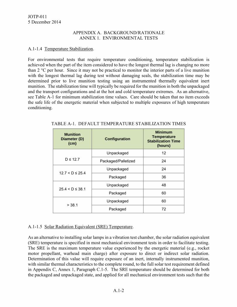
A.1-1.4 Temperature Stabilization. For environmental tests that require temperature conditioning, temperature stabilization is achieved when the part of the item considered to have the longest thermal lag is changing no more than 2 °C per hour. Since it may not be practical to monitor the interior parts of a live munition with the longest thermal lag during test without damaging seals, the stabilization time may be determined prior to live munition testing using an instrumented thermally equivalent inert munition. The stabilization time will typically be required for the munition in both the unpackaged and the transport configurations and at the hot and cold temperature extremes. As an alternative, see Table A-1 for minimum stabilization time values. Care should be taken that no item exceeds the safe life of the energetic material when subjected to multiple exposures of high temperature conditioning.
TABLE A-1. DEFAULT TEMPERATURE STABILIZATION TIMES
Munition Diameter (D)
(cm) Configuration
Minimum Temperature
Stabilization Time (hours)
D ≤ 12.7
Unpackaged 12
Packaged/Palletized 24
12.7 < D ≤ 25.4 Unpackaged 24
Packaged 36
25.4 < D ≤ 38.1 Unpackaged 48
Packaged 60
> 38.1 Unpackaged 60
Packaged 72
A.1-1.5 Solar Radiation Equivalent (SRE) Temperature. As an alternative to installing solar lamps in a vibration test chamber, the solar radiation equivalent (SRE) temperature is specified in most mechanical environment tests in order to facilitate testing. The SRE is the maximum temperature value experienced by the energetic material (e.g., rocket motor propellant, warhead main charge) after exposure to direct or indirect solar radiation. Determination of this value will require exposure of an inert, internally instrumented munition, with similar thermal characteristics to the complete round, to the full solar test requirement defined in Appendix C, Annex 1, Paragraph C.1-5. The SRE temperature should be determined for both the packaged and unpackaged state, and applied for all mechanical environment tests such that the
JOTP-011 5 December 2014
APPENDIX A. BACKGROUND/RATIONALE ANNEX 1. ENVIRONMENTAL TESTS
A.1-3
packaged SRE is used for packaged tests and the unpackaged SRE for the unpackaged tests. In the absence of this data, a value of +71 °C should be used in lieu of the SRE temperature since this reflects the maximum value of the A1 Storage and Transit diurnal cycle defined in MIL-STD-810. A.1-2 CLIMATIC ENVIRONMENT TESTS (APPENDIX C, ANNEX 1). Provided below are rationale for the climatic tests. Select the test item configuration (packaged or unpackaged) that exposes the munition to the most severe environmental condition. In most, but not all cases, this is likely to be the unpackaged, bare munition configuration. Some munitions are encased in a launch tube or container and packaged in a wooden or metal overpack shipping container. In this case, climatic testing would be conducted with the munition in the launch tube/container. In many cases, the shipping/storage container is the launch container (i.e., SLC) and thus, would be the packaged configuration for all tests. Test the munition using the appropriate packaging configuration (see Figure 2). A.1-2.1 Humid Heat (Appendix C, Annex 1, Paragraph C.1-1). The humid heat test is performed to determine the resistance of materiel to the effects of a warm humid atmosphere. Materiel may be exposed to this environment year-round in tropical areas and seasonally in mid-latitude areas. The procedure recommended by this document is an aggravated test. It does not reproduce naturally occurring or service-induced temperature-humidity scenarios. In order to reduce the time and cost of testing, the test item is exposed to higher temperature and humidity levels than those found in nature; however, the exposure duration is shorter. A minimum of ten test cycles has proven to be effective at inducing degradation/failures that are indicative of long-term effects. For test items incorporating seals which protect moisture sensitive materials, longer test durations may be required to obtain a higher degree of confidence that the munition will remain S3 in warm-humid conditions. A.1-2.2 Temperature Storage and Cycling (Appendix C, Annex 1, Paragraphs C.1-2 through C.1-4). Low and high temperature testing is carried as part of the sequential trials program in order to induce thermo-mechanical stressing and accelerated ageing in the test munition. A.1-2.2.1 Low Temperature Storage and Cycling (Appendix C, Annex 1, Paragraph C.1-2). The low-temperature storage test is intended to determine the effects of low-temperature storage on the munition. There is a 1 percent probability that ammunition deployed in arctic areas (Category C3, MIL-STD-810) will be exposed to a temperature of -51 °C. Category C3 applies to the coldest area of the North American continent and the areas surrounding the coldest parts of Siberia and Greenland. The low temperature can be expected to dwell once reached with no solar heating effects. A minimum of 3 days is recommended since this is considered sufficient duration to thermally stabilize the munition. If, however, other cold temperature degradation mechanisms
JOTP-011 5 December 2014
APPENDIX A. BACKGROUND/RATIONALE
ANNEX 1. ENVIRONMENTAL TESTS
A.1-4
are likely such as those related to constant strain at cold temperatures, then longer durations may be required and guidance should be sought from the munition designer. If the munition under test could be susceptible to thermo-mechanical stresses due to low temperature fluctuations, the C2 low temperature cycle or that defined in the LCEP should be used. The low-temperature cycling test is intended to determine the effects of low-temperature operational environments on the munition (storage at extreme cold is addressed by the cold temperature storage test). The temperatures associated with the low-temperature cycling test are created by meteorological air temperatures (note that at this temperature extreme, the meteorological and induced diurnal cycles become aligned). The induced air temperature diurnal cycle (C2) for Category C storage and transit conditions given in MIL-STD-810, Method 502 is considered to adequately encompass most conceivable situations. A.1-2.2.2 High Temperature Storage and Cycling (Appendix C, Annex 1, Paragraphs C.1-3 and C.1-4). The high temperature cycling test is intended to determine the effects of thermo-mechanical stresses on the munition. The induced air temperature diurnal cycle for Category A1 storage and transit conditions given in MIL-STD-810 Method 501 is considered to adequately encompass most conceivable situations. For other environments, such as Naval controlled environments, other storage categories may be considered and are LCEP dependent. The high temperature storage test is intended to accelerate chemical and physical based degradation mechanisms via a period of testing using a constant elevated temperature. A constant temperature of +71 °C is the maximum temperature that should be considered since this reflects the peak temperatures likely to be encountered during field storage or deployment in an A1 climate zone. Alternatively, a constant temperature of +58 °C may be more appropriate where the use of +71 °C is thought to generate unrealistic degradation. For most munitions, 28 hot A1 induced diurnal cycles are considered sufficient to induce thermo-mechanical stressing representative of that which could occur in service. For chemical and/or physical ageing processes (e.g., stabilizer depletion or diffusion of chemical substances) longer durations are necessary to produce sufficient observable change; and 56 hot diurnal cycles have historically provided sufficient confidence to support an initial deployment of up to at least 6 months tactical storage. Chemical and physical processes may be simulated by constant temperature stressing, but care must be exercised since such stressing may induce unrepresentative failure modes or may not adequately exercise potential failure modes. Consideration must be given to the design of the munition and any design limitations. For example, gas cracking, phase changes or changes in the chemical reaction mechanism can occur during constant temperature ageing which may not occur during diurnal cycling or in service. This test should not be conducted instead of high temperature cycling, but may be used to supplement the chemical ageing effects of diurnal cycling tests. If the munition under test could be susceptible to high temperature fluctuations, then the A1 storage and transit (induced) cycle or that defined in the LCEP should be used.

JOTP-011 5 December 2014
APPENDIX A. BACKGROUND/RATIONALE ANNEX 1. ENVIRONMENTAL TESTS
A.1-5
If opting to substitute some of the hot diurnal cycles for fixed temperature stressing; only 28 of the 56 cycles should be substituted (with the remaining 28 cycles being applied along with the constant thermal stressing). Using the Arrhenius kinetic model discussed in STANAG 4370, AECTP 300 Method 306, Paragraph 2.4.2 ‘Test Duration’, and an activation energy of 70 kJ/mol; constant temperature stressing may be applied for 216 hours (9 days) at +71 °C, or 528 hours (22 days) at +58 °C where unrealistic degradation is anticipated at +71 °C. It should be noted that laboratory based ageing studies using small samples of material do not take account of the geometry of the component and so some potential degradation mechanisms could be missed. Furthermore, it should be noted that the thermal ramp conditioning time should not be counted towards life estimates since it can prove difficult to determine the amount of thermal energy input to the munition. Therefore, it is difficult to model the equivalent ageing likely to have occurred within the munition. Whatever ageing tests are conducted as part of the sequential trials program, the resulting predictions must be compared with the results of in-service surveillance to determine how accurate they were and whether any potential failure modes were missed. A.1-2.3 Solar Radiation (Appendix C, Annex 1, Paragraph C.1-5). This test is intended to aggravate those thermally induced degradation mechanisms associated with elevated skin temperatures and thermal gradients within the weapon, that are induced due to solar radiation. Since most Nations solar test chambers do not incorporate the ultraviolet element of the spectrum they tend not to aggravate the photo-chemical (actinic) degradation modes associated with solar radiation. If this is of concern (as may be the case for some paints, adhesives and polymers) then a separate ultra-violet exposure test will also be required. A minimum of seven A1 climate category cycles (meteorological temperature and solar radiation) is recommended in order to attain the maximum elevated temperatures throughout the test item. The solar radiation level of 1120 W/m² is derived from MIL-STD-810, Method 505. A.1-2.4 Thermal Shock (Appendix C, Annex 1, Paragraph C.1- 6). This test is intended to simulate the rapid temperature transitions that are possible during logistic movements of munitions. Two possible approaches are described below. Examine the munition usage scenarios to determine the test item packaging configuration. If feasible, all testing should be carried out on unpackaged items to provide worst case thermal stress conditions. Stabilization at the temperature extremes is required.
JOTP-011 5 December 2014
APPENDIX A. BACKGROUND/RATIONALE
ANNEX 1. ENVIRONMENTAL TESTS
A.1-6
A.1-2.4.1 Phased Thermal Shock. A.1-2.4.1.1 Low Temperature Phase (Appendix C, Annex 1, Paragraph C.1-6a). This test simulates movement of warm munitions from storage or from a transport vehicle in maintenance to an extreme cold environment or vice versa. The low temperature shock test consists of five temperature shock cycles between the temperatures of 21 °C (standard ambient) and -51 °C. In most applications, the munition will be exposed to the temperature shock environment in its logistic container. However, to address the most severe condition the munition should be tested in its unpackaged configuration. a. The -51 °C temperature is the low extreme presented in MIL-STD-810, Method 503, for Climate Category C3. b. Stabilization at the temperature extremes is required. Munitions in storage or in warm buildings associated with vehicle maintenance would likely achieve temperature stabilization. Also, the extremely low temperatures encountered in the natural environment are likely to persist longer than the munition temperature stabilization time. A.1-2.4.1.2 High Temperature Phase (Appendix C, Annex 1, Paragraph C.1-6b). This test exposes the munitions to rapid temperature transition from -5 °C (temperature at an altitude of 8 km, from MIL-STD-810, Method 503) to the unpackaged SRE temperature. a. This test simulates rapid movement of munitions under the following scenarios: (1) Movement of warm munitions from storage (e.g., magazine or process area) to an extreme cold environment, or vice versa; (2) Rapid ascent from a desert airfield to high altitude (8 km) in an unheated aircraft compartment or carried externally. (3) Air delivery or airdrop from high altitude (8 km) to a desert environment. b. Stabilization at the temperature extremes is required. Munitions in flight prior to air delivery would likely achieve temperature stabilization. Also, the extremely high temperatures encountered in the natural environment are likely to persist longer than the munition temperature stabilization time. A.1-2.4.2 Aggravated Thermal Shock. a. The handling and transport of munitions between a temperature conditioned storage area and the ambient outdoor environment is the prevailing mechanism for rapid thermal change.

JOTP-011 5 December 2014
APPENDIX A. BACKGROUND/RATIONALE ANNEX 1. ENVIRONMENTAL TESTS
A.1-7
This test does not simulate a specific transport scenario but it uses the rapid transition between the extreme temperature values to thermally stress the munition. b. In this scenario, a single set of temperature shocks will be required. The temperature shock test consists of ten cycles from a cold extreme temperature of -51 °C to the high extreme temperature of no less than 71 °C. The transfer rate between chambers should be as fast as possible and is dependent upon munition portability requirements (i.e., man vs. machine). A.1-2.5 Immersion /Pressurization (Appendix C, Annex 1, Paragraph C.1-7). a. Munitions may be exposed to water immersion during fording. The immersion test determines if the ingress of water affects materials and safe operation of the munition. This test requires temperature conditioning of the munition to establish a pressure differential (on cooling) to determine whether the seals or gaskets leak under relatively low pressure differential, and to induce expansion/contraction of materials. Temperature conditioning the item to 27 °C above the water temperature represents exposure to solar heating immediately prior to immersion. Thirty minutes of immersion at a depth of one meter is required. b. Munitions intended for underwater launch are normally exposed to hydrostatic pressure related to its launch depth. The test requires the munition to be conditioned as it would prior to and during the launch. With the munition properly conditioned, the munition shall be subjected to a hydrostatic pressure of 110% of the baseline specified launch pressure. A.1-2.6 Salt Fog (Appendix C, Annex 1, Paragraph C.1-8). a. The salt fog test (MIL-STD-810, Method 509) provides a set of repeatable conditions to determine the relative resistance of the munition to the effects of an aqueous salt atmosphere. This test locates potential problem areas, quality control deficiencies, design flaws, etc., in a relatively short period of time and is required for munitions that will experience significant exposure (as opposed to infrequent or irregular) to high levels of salt in the atmosphere. It should be noted that testing at the component level may not address galvanic corrosion. b. As a minimum, this JOTP requires two cycles of alternating wet-dry-wet-dry conditions of 24 hours each to be imposed. Experience has shown that alternating periods of salt fog exposure and drying conditions provides a more realistic exposure and a higher damage potential than does continuous exposure to a salt atmosphere. The munition is tested in the most vulnerable configuration (packaged or unpackaged) as identified in the LCEP. The number of cycles may be increased if a higher degree of confidence is required to assess the ability of the materials involved to withstand a corrosive environment (e.g., sea based munitions stored above deck may require additional cycles). Note, there is no relationship between this test and any real world exposure duration but it does provide an indication of potential problem areas associated with the salt (maritime) environment, nearby water sources, and from salted roads during winter operations.
JOTP-011 5 December 2014
APPENDIX A. BACKGROUND/RATIONALE
ANNEX 1. ENVIRONMENTAL TESTS
A.1-8
A.1-2.7 Sand and Dust (Appendix C, Annex 1, Paragraph C.1-9). a. The sand and dust test (MIL-STD-810, Method 510, Procedures I and II) determines the effects on munitions after exposure to dust and sand laden atmospheres. Dust consists of particle sizes less than 150 microns. Sand has particle sizes greater than or equal to 150 microns. Underwater launched munitions do not typically experience this environment as part of its LCEP, so there would be no test requirement for these munitions. b. Munitions may be exposed to sand and dust environments on a worldwide basis. The greatest exposure would be expected during operations in desert regions due to vehicle convoys and aircraft/helicopter movements. The movement of military vehicles in hot dry desert regions or in areas where the surface is liable to break up into small particulate is liable to result in dust and sand-laden atmospheres. Munitions may also be transported by personnel during operation of aircraft on airfields and are likely to be directly subjected to artificially blown dust and sand. Material deposited inside the munition may cause short-circuiting, build-up of static electricity, interference between moving parts, and contamination of any lubrication systems. This JOTP requires the munition to be tested in the most severe deployment configuration using the most severe exposure parameters defined in Procedures I and II of Method 510. A.1-2.8 Rain/Watertightness (Appendix C, Annex 1, Paragraph C.1-10). The rain test (MIL-STD-810, Method 506, Procedure I) recommends using a 100 ± 20 mm/hr severity for a duration of two hours. This severity is considered adequate to address exposure throughout most of the world apart from tropical zones where rainfall rates can be much higher. If deployment to tropical zones is anticipated then the munition should probably be subjected to the higher severity of 200 ± 50 mm/hr. However, it should also be considered whether the munition will actually be fielded during a tropical rainstorm. If not then the ‘typical’ worldwide severity would be adequate. This JOTP requires the munition to be tested in the most severe transport configuration as determined by the LCEP. The wind speed of 18 m/s is consistent with MIL-STD-810, Method 506, Procedure 1. A.1-2.9 Icing (Appendix C, Annex 1, Paragraph C.1-11). Munitions are likely to be exposed to severe icing in cold climates. The icing test (MIL-STD-810, Method 521) determines the potential damaging effects of icing on the munition where stresses are imposed at joints and interfaces of adjacent parts. Damage may also be incurred as a result of the methods used to remove the ice and the subsequent accumulation of moisture after melting of the ice. The principal sources of ice are frosting, freezing rain, refreezing of thawing snow, and freezing of condensation. The thickness of the ice deposited on the item depends upon the duration of the exposure and the contours of the munition. Medium ice loading conditions are required by this JOTP with the munition being in the most severe deployment configuration as determined by the LCEP.
JOTP-011 5 December 2014
APPENDIX A. BACKGROUND/RATIONALE ANNEX 1. ENVIRONMENTAL TESTS
A.1-9
A.1-2.10 Cargo Aircraft Decompression (Appendix C, Annex 1, Paragraph C.1-12). Rapid decompression can result when cabin pressurisation is lost during an accident scenario in a transport aircraft. Rapid decompression may result in damage to munition seals during cargo aircraft transportation. This test should be conducted using packaged munitions to verify that the packaging does not present a secondary hazard to the munition or aircraft crew. An initial cargo compartment pressurisation of 60 kPa is sufficient to address most common military transport aircraft worldwide. A.1-2.11 Mould Growth (Fungus and Biological Hazards) (Appendix C, Annex 1, Paragraph C.1-13). Microbial deterioration is a function of temperature and humidity and is an inseparable condition of hot-humid tropics and the mid-latitudes. MIL-STD-810, Method 508 is used to determine if mould growth will occur and, if so, how it may degrade/impact the use of the munition. Twenty-eight days is the minimum test period to allow for mould germination, breakdown of carbon-containing molecules, and degradation of material. This is a non-sequential test and may be conducted on leftover components or material samples. A.1-2.12 Contamination by Fluids (Appendix C, Annex 1, Paragraph C.1-14). Contamination of the munition may arise from exposure to fuels, hydraulic fluids, lubricating oils, solvents and cleaning fluids, de-icing and anti-freeze fluids, insecticides, sunblock, disinfectants, coolant dielectric fluid, and fire extinguishants. Select the fluids most commonly encountered throughout the munitions life cycle and apply to the item in the most severe deployment configuration as determined by the LCEP. Use the intermittent exposure method described in MIL-STD-810, Method 504. Contamination effects must be analyzed for its immediate or potential (long term) effects on the proper functioning or safety of the munition. A.1-3 MECHANICAL ENVIRONMENT TESTS (APPENDIX C, ANNEX 2). Provided below are the rationale for the dynamic environments likely to result from normal usage in severe environmental conditions, or from plausible mishandling during logistic and field operations. The weapons should be tested following temperature conditioning at either the SRE temperature (packaged or unpackaged as appropriate for the test configuration) for the hot weapons and -46 °C for the cold weapons (rationale given at Annex 1, paragraphs A.1-1.3 and A.1-1.5). For naval launched munitions, temperature conditioning using the M3 and A1 cycles may be applicable when the storage conditions are not well defined by the LCEP. Operational temperature conditions for submarine munitions are more controlled within a limited range.
JOTP-011 5 December 2014
APPENDIX A. BACKGROUND/RATIONALE
ANNEX 1. ENVIRONMENTAL TESTS
A.1-10
A.1-3.1 Logistic Transportation Dynamics. Surface and underwater launched munitions may be subjected to logistic land transportation by either commercial or military vehicles. Distances for each mode of transport are specified in AECTP 100. Each of these environments must be addressed as applicable. Table A-2 is an example of the logistic land transportation dynamics requirements in the current versions of AECTP 100 and MIL-STD-810, Method 514. A.1-3.1.1 Logistic Land Transportation Dynamics (Commercial). A.1-3.1.1.1 Logistic Wheeled Vehicle Transportation Dynamics (Appendix C, Annex 2, Paragraph C.2-1.1). The movement of packaged materiel from the point of manufacture to the storage location is usually accomplished by commercial logistic vehicles over improved or paved highways. This can be addressed by the ‘Common Carrier’ vibration profiles in MIL-STD-810, Method 514. No factors of safety need to be applied to the amplitude since MIL-STD-810 vibration schedules are specified. These vibration schedules have been developed from field data and have conservatism factors built into them. Common Carrier vibration should be applied for a duration equivalent to the distances shown below in Table A-2. This is the first test to be performed in the munition life cycle test sequences of Appendix B. The intent is to degrade the shipping container and weapon seals prior to the climatic environmental tests. A.1-3.1.1.2 Packaged Transit Drop (Appendix C, Annex 2, Paragraph C.2-1.2). The packaged transit drop test simulates accidental drops encountered in logistical (packaged) handling of the munitions such as a hovering helicopter dropping the munitions from a sling or the unloading of munitions stacked on a truck. The munitions could be transported in either the single munition or bulk munition (palletized) configuration. Shipping containers may double as munition launch containers which could be loaded with multiple munitions (e.g., a launch container may have 6 rockets). All S3 test assets in the sequential environmental test flow are exposed to the Packaged Transit Drops. Munitions dropped from these heights are typically expected to remain safe for use. a. The default drop heights shown in Table C.2-1 (adapted from MIL-STD-810, Method 516) are based on the size and weight of a packaged munition. Note that the LCEP may define handling scenarios where the drop height differs, such as for small 2-man-portable packaged munitions stacked on a truck where a drop height approaching 2.1 m could be applicable. Consideration should be given to conducting greater severity drops non-sequentially depending upon the LCEP.

JOTP-011 5 December 2014
APPENDIX A. BACKGROUND/RATIONALE ANNEX 1. ENVIRONMENTAL TESTS
A.1-11
TABLE A-2. LOGISTIC LAND TRANSPORTATION TEST DURATION EXAMPLES BASED ON AECTP 100-4 AND MIL-STD-810
Munition
Type
AECTP 100-4
Logistic Land Transport Distance1
Transport Mode
Percentage of AECTP
100-4 Distance2
JOTP-011 Default
Distances
MIL-STD-810 Test Relation
to Field Exposure3
JOTP-011 Test Durations
Land
10,000 km Commercial
Vehicle
Secured Cargo – Common Carrier
48% 4800 km
Vibration: Vertical Axis
1hr/axis = 4000 km
Longitudinal and Transverse Axes
1hr/axis = 1609 km
Vert: 72 min/axis
Long/Trans: 179 min/axis
Number of Restrained Cargo Shocks to be equivalent to 4800 km
No requirement if
military wheeled vehicle
transport shocks are performed.
10,000 km Military Vehicle
Secured Cargo – Common Carrier
20% 2000 km
Vibration: Vertical Axis
1hr/axis = 4000 km
Longitudinal and Transverse Axes:
1hr/axis = 1609 km
No requirement to
test since addressed by
other environments.
Secured Cargo – Tactical Wheeled
Vehicle 8% 800 km
Vibration: All Axes
40 min/axis = 805 km
40 min/axis
Number of Restrained Cargo Shocks in
Table C2-1 = 800 km
See Table C2-1
Secured Cargo – Tracked Vehicle4
2.5% 250 km Vibration: All Axes:
45 min/axis = 160 km 70 min/axis
Two Wheeled Trailer4
0.5% 50 km Vibration: All Axes:
32 min/axis = 52 km 32 min/axis
*See notes on next page.

JOTP-011 5 December 2014
APPENDIX A. BACKGROUND/RATIONALE
ANNEX 1. ENVIRONMENTAL TESTS
A.1-12
TABLE A-2. LOGISTIC LAND TRANSPORTATION TEST DURATION EXAMPLES BASED ON AECTPS 100-4 AND 400-3 (CONTINUED)
Munition Type
AECTP 100-4 Logistic Land
Transport Distance1
Transport Mode
Percentage of AECTP
100-4 Distance2
JOTP-011 Default
Distances
MIL-STD-810 Test Relation
to Field Exposure3
JOTP-011 Test Durations
(min/axis)
Sea
5,000 km Commercial
Vehicle
Secured Cargo – Common Carrier
96% 4800 km
Vibration: Vertical Axis:
1hr/axis = 4000 km
Longitudinal and Transverse Axes:
1hr/axis = 1609 km
Vert: 72 min/axis
Long/Trans: 179 min/axis
Number of Restrained Cargo Shocks
to be equivalent to 4800 km
No requirement if
military wheeled vehicle
transport shocks are performed.
5,000 km Military Vehicle
Secured Cargo –Common Carrier
4% 200 km
Vibration: Vertical Axis:
1hr/axis = 4000 km
Longitudinal and Transverse Axes:
1hr/axis = 1609 km
No requirement to
test since addressed by
other environments.
Secured Cargo – Tactical Wheeled Vehicle (includes 4 wheeled trailer)
4% 200 km
Vibration: All Axes:
40 min/axis = 805 km
10 min/axis
Number of Restrained Cargo Shocks in
Table C2-1 = 200 km
See Table C2-1
NOTE 1: AECTP 100-4 distances are provided as examples only and reflect potential cumulative life distances. Use the most current AECTP 100 values. NOTE 2: Percentage values of the AECTP 100-4 distance reflects the worst case distances likely to be experienced during one deployment cycle. For multiple deployments, additional mileage may be added as determined by the munition LCEP. In some cases, a follow-on surveillance program will address a multiple deployment scenario. NOTE 3: MIL-STD-810 time/distance relationships are provided as examples only. Use the most current MIL-STD-810 values. In some cases, platform specific environments may change this relationship (e.g., munition transported only on one tactical wheeled vehicle). NOTE 4: Tracked Vehicle and Two Wheeled Trailer transportation environments may not be required. Refer to the LCEP for applicability.
JOTP-011 5 December 2014
APPENDIX A. BACKGROUND/RATIONALE ANNEX 1. ENVIRONMENTAL TESTS
A.1-13
b. Drop heights and/or orientations may be tailored taking due account of the fragility of the munition to be tested, with the tailoring rationale being documented in the S3 Safety Data Package. The tailored drop height and/or orientation represents the maximum severity the munition can survive to remain safe for use. This munition specific drop height and/or orientation will be documented in the Field Maintenance/Technical Manuals. If a munition exceeds the aforementioned drop specifications, removal of this individual munition from service will be required for further assessment or disposal. A.1-3.1.1.3 Logistic Rail Transportation Dynamics (Appendix C, Annex 2, Paragraph C.2-1.3). a. Rail transport vibration would normally be conducted in accordance with MIL-STD-810, Method 514. Based on an assessment that this environment is relatively benign compared to other S3 test environments, this test was eliminated as a requirement for surface and underwater launched munitions. b. Rail impact testing is conducted in accordance with MIL-STD-810, Method 526. Large munitions can be vulnerable to load shifting within their shipping container causing damage to the detent system or munition restraining device. This is especially important for munitions which use the shipping container for dual purposes; i.e., transportation and munition launch. For S3 testing a pendulum swing or inclined (horizontal) velocity impact machine, a rail impact test facility, or an equivalent configuration may be used to perform the test. The S3 asset may also be used for U.S. military transportation certification if the test is conducted at a rail facility. Alternatively, non-sequential inert assets with similar mass and structural characteristics may be used to attain transportation certification independently of the S3 program. A.1-3.1.2 Logistic Transport Dynamics (Military). Military transportation for surface and underwater launched munitions can be subdivided to address military logistic and tactical movements. Logistic movement includes transportation from a point of entry into the theatre of operations to an airfield storage site, forward operating base, or naval vessel. These movements may include land, sea, and air transportation on military vehicles. Tactical movement addresses transportation from the storage site to the firing platform. A.1-3.1.2.1 Military Land Transportation Dynamics. Military land vehicle transportation from a point of arrival into the theatre of operations up to a storage area may be as secured cargo on wheeled vehicles, trailers, and/or tracked vehicles. Although most sea based munitions transportation would be expected to be over improved or paved highways, a portion may be by degraded road. Land based munitions are more likely to be deployed to forward operating bases which requires transportation on degraded roads. Vehicle vibration and restrained cargo shock environments must be addressed.

JOTP-011 5 December 2014
APPENDIX A. BACKGROUND/RATIONALE
ANNEX 1. ENVIRONMENTAL TESTS
A.1-14
A.1-3.1.2.1.1 Military Wheeled Vehicle Dynamics (Appendix C, Annex 2, Paragraphs C.2-2.1 and C.2-2.2). a. Military land transportation as secured cargo on wheeled vehicles consists of both vibration and shock elements that require individual tests to fully address the environment. Furthermore, military land transportation may incorporate aspects of both on- and off-road movement. The vibration element of this environment can be addressed by the profiles in MIL-STD-810, Method 514 for a ‘Tactical Wheeled Vehicle’ using a duration equivalent to distances shown in Table A-2. Since a mission profile, incorporating both on- and off-road movement, was considered during development of the tactical wheeled vehicle vibration spectra there is no requirement for separate tests to address these two aspects of the environment. b. Some weapon systems require special military transport vehicles. These vehicles most likely are not addressed in the Method 514 ‘Tactical Wheeled Vehicle’ vibration test schedule. In this case tailored test specifications need to be developed based upon measured field data. c. Restrained cargo shock testing is required to address minor obstacle negotiation for wheeled vehicles, particularly those travelling in an off-road role. This environment must be conducted in order to meet the dynamic test requirements, and individual elements cannot be tailored out. The Restrained Cargo Transport Shock levels in MIL-STD-810, Method 516 are considered sufficient to satisfy the intent of this test and are specified in Annex C, Table C2-1. d. These tests should be conducted in the configuration identified in the LCEP for this mode of transportation. Note that sea launched munitions movement may be limited to short distances as defined in the LCEP. See Table A-2 for an example of transport distance and test duration. Tailor the tests accordingly. A.1-3.1.2.1.2 Two Wheeled Trailer Vibration (Appendix C, Annex 2, Paragraph C.2-2.3). Transportation of surface and underwater munitions on a two-wheeled trailer is unlikely although transport of small land based munitions is possible. If two wheeled trailer transport is identified as part of the LCEP, the environment can be addressed by the vibration profiles in MIL-STD-810, Method 514 for ‘Two Wheeled Trailer’. A.1-3.1.2.1.3 Tracked Vehicle Transportation Vibration (Appendix C, Annex 2, Paragraph C.2-2.4). Transportation of sea based munitions on tracked vehicles is unlikely and need not be considered unless identified as part of the LCEP. Transport of land based munitions by a tracked vehicle is a possible transport mode. This environment can be addressed by the vibration profiles in MIL-STD-810, Method 514 and ITOP 01-2-601 using a duration equivalent to the distance specified in the LCEP. Typically, the shock aspects associated with this environment are addressed by other tests in the sequence so there is no requirement to address these specifically.
JOTP-011 5 December 2014
APPENDIX A. BACKGROUND/RATIONALE ANNEX 1. ENVIRONMENTAL TESTS
A.1-15
A.1-3.1.2.1.4 Loose Cargo Repetitive Shock (Appendix H, Annex 4, Paragraph H.4-10). Transportation of surface and underwater munitions as loose, or unsecured, cargo is unlikely and need not be considered unless identified as part of the LCEP. Note this mode of transport could be applicable to small land based munitions. If loose cargo is identified as part of the LCEP, then testing is required within the environmental sequence. Test in accordance with MIL-STD-810, Method 514. Since no overall distance is specified in AECTP 100, the default of 20 minutes testing time as per MIL-STD-810, Method 514 is sufficient for most applications. A.1-3.1.2.2 Military Sea Transportation Dynamics.
A.1-3.1.2.2.1 Shipboard Vibration (Appendix C, Annex 2, Paragraph C.2-3.1). For transportation of land based munitions by military ships, vibration testing is not normally required since this environment tends to be relatively benign compared to other vibration environments within the LCEP. For sea based munitions Ship Vibration testing is considered necessary. The test should be conducted in accordance with MIL-STD-810, Method 528. A.1-3.1.2.2.2 Shipboard Shock (Underwater Explosion) (Appendix C, Annex 2, Paragraph C.2-3.2). The shocks likely to occur during non-contact underwater explosion (UNDEX) cause significant shock amplitudes that exceed those from normal handling. UNDEX shock testing in accordance with MIL-S-901 or appropriate International Standards is a mandatory requirement prior to ship embarkation for some NATO Nations and cannot be tailored out. The overall basis for UNDEX shock is addressed in Allied Navy Engineering Publication (ANEP) 43. Additional guidance may be found in STANAGs 4549 and 4150. The temperature in the ship’s hold would be expected to be relatively benign, so testing may be performed under standard ambient conditions (+21 °C). The typical requirement would be for the munitions to remain ‘Safe for Disposal’ so testing may be conducted non-sequentially. If, however, the requirement is for the munitions to remain ‘Safe for Use’ (as may be necessary for Naval application) UNDEX shock testing must be conducted within the sequence. A.1-3.1.2.3 Military Air Transportation Dynamics. Surface and underwater launched munitions may be subjected to Military Air transportation by either fixed wing transport aircraft (jet and propeller) or helicopters as determined by the LCEP. Distances for each mode of transport are specified in AECTP 100. Each of these environments must be addressed as applicable. Table A-3 summarizes the military air transportation dynamics requirements as an example based on the current versions of AECTP 100 and MIL-STD-810. Method 514.

JOTP-011 5 December 2014
APPENDIX A. BACKGROUND/RATIONALE
ANNEX 1. ENVIRONMENTAL TESTS
A.1-16
TABLE A-3. AIRCRAFT CARGO TRANSPORTATION TEST DURATION EXAMPLES BASED ON AECTPS 100-4 AND MIL-STD-810
Transport Mode Munition Type
AECTP 100-41 Flight Durations for Land Vehicle and Naval Munitions
MIL-STD-8102 Test Relation to Field
Exposure
JOTP-011 Test
Durations
Fixed Wing Cargo Jet
Land Based 100 hours 1 min/takeoff (10 hr flight/takeoff)
10 min/axis
Sea Based 50 hours 5 min/axis
Fixed Wing Cargo
Turboprop
Land Based 100 hours 1 hr/axis (no equivalence)
1 hr/axis
Sea Based 50 hours 1 hr/axis
Helicopter Internal Cargo
Land Based 20 hours 1 hr/axis = 6 hrs flight
3.33 hrs/axis
Sea Based 5 hours 50 min/axis
NOTE 1: AECTP 100-4 Distances provided as examples only. The most current AECTP 100 values should be applied. NOTE 2: MIL-STD-810 Time/Distance Relations provided as examples only. The most current MIL-STD-810 values should be applied. A.1-3.1.2.3.1 Fixed Wing Turboprop Aircraft Vibration (Appendix C, Annex 2, Paragraph C.2-4.1.1). The most common propeller cargo aircraft used throughout NATO is the C130, of which the four and six bladed propeller variants are most typical (4-blade, f0=68 Hz and 6-blade, f0=102 Hz). The vibration severities for these aircraft are defined in MIL-STD-810, Method 514, Annex C, for ‘Propeller Aircraft’. If other cargo aircraft are identified as part of the LCEP, then the blade frequencies (f0) for these shall also require consideration. Since it is not always possible to predetermine the specific aircraft types that will be used during transportation, the total test duration based on the total flight duration defined in AECTP 100, Annex E, Appendix 1 for each commodity type transported by ‘Propeller Aircraft’ should be split between the different blade frequencies (f0) identified. For C130, this will require the test to be divided equally between the two blade frequencies (f0 = 68 Hz and 102 Hz) as a minimum. A.1-3.1.2.3.2 Fixed Wing Jet Aircraft Vibration (Appendix C, Annex 2, Paragraph C.2-4.1.2). The vibration environment associated with cruise is largely addressed by other vibration environments within the LCEP and need not necessarily be tested. The take-off vibration environment is significantly more severe than that for cruise, and can be addressed by the vibration profiles in MIL-STD-810, Method 514, Annex C for ‘Jet Aircraft Cargo’. The duration of this test
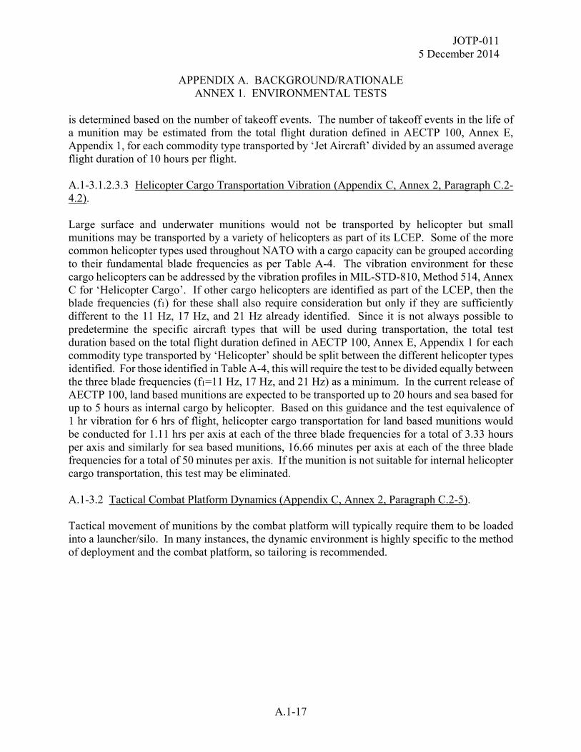
JOTP-011 5 December 2014
APPENDIX A. BACKGROUND/RATIONALE ANNEX 1. ENVIRONMENTAL TESTS
A.1-17
is determined based on the number of takeoff events. The number of takeoff events in the life of a munition may be estimated from the total flight duration defined in AECTP 100, Annex E, Appendix 1, for each commodity type transported by ‘Jet Aircraft’ divided by an assumed average flight duration of 10 hours per flight. A.1-3.1.2.3.3 Helicopter Cargo Transportation Vibration (Appendix C, Annex 2, Paragraph C.2-4.2). Large surface and underwater munitions would not be transported by helicopter but small munitions may be transported by a variety of helicopters as part of its LCEP. Some of the more common helicopter types used throughout NATO with a cargo capacity can be grouped according to their fundamental blade frequencies as per Table A-4. The vibration environment for these cargo helicopters can be addressed by the vibration profiles in MIL-STD-810, Method 514, Annex C for ‘Helicopter Cargo’. If other cargo helicopters are identified as part of the LCEP, then the blade frequencies (f1) for these shall also require consideration but only if they are sufficiently different to the 11 Hz, 17 Hz, and 21 Hz already identified. Since it is not always possible to predetermine the specific aircraft types that will be used during transportation, the total test duration based on the total flight duration defined in AECTP 100, Annex E, Appendix 1 for each commodity type transported by ‘Helicopter’ should be split between the different helicopter types identified. For those identified in Table A-4, this will require the test to be divided equally between the three blade frequencies (f1=11 Hz, 17 Hz, and 21 Hz) as a minimum. In the current release of AECTP 100, land based munitions are expected to be transported up to 20 hours and sea based for up to 5 hours as internal cargo by helicopter. Based on this guidance and the test equivalence of 1 hr vibration for 6 hrs of flight, helicopter cargo transportation for land based munitions would be conducted for 1.11 hrs per axis at each of the three blade frequencies for a total of 3.33 hours per axis and similarly for sea based munitions, 16.66 minutes per axis at each of the three blade frequencies for a total of 50 minutes per axis. If the munition is not suitable for internal helicopter cargo transportation, this test may be eliminated. A.1-3.2 Tactical Combat Platform Dynamics (Appendix C, Annex 2, Paragraph C.2-5). Tactical movement of munitions by the combat platform will typically require them to be loaded into a launcher/silo. In many instances, the dynamic environment is highly specific to the method of deployment and the combat platform, so tailoring is recommended.
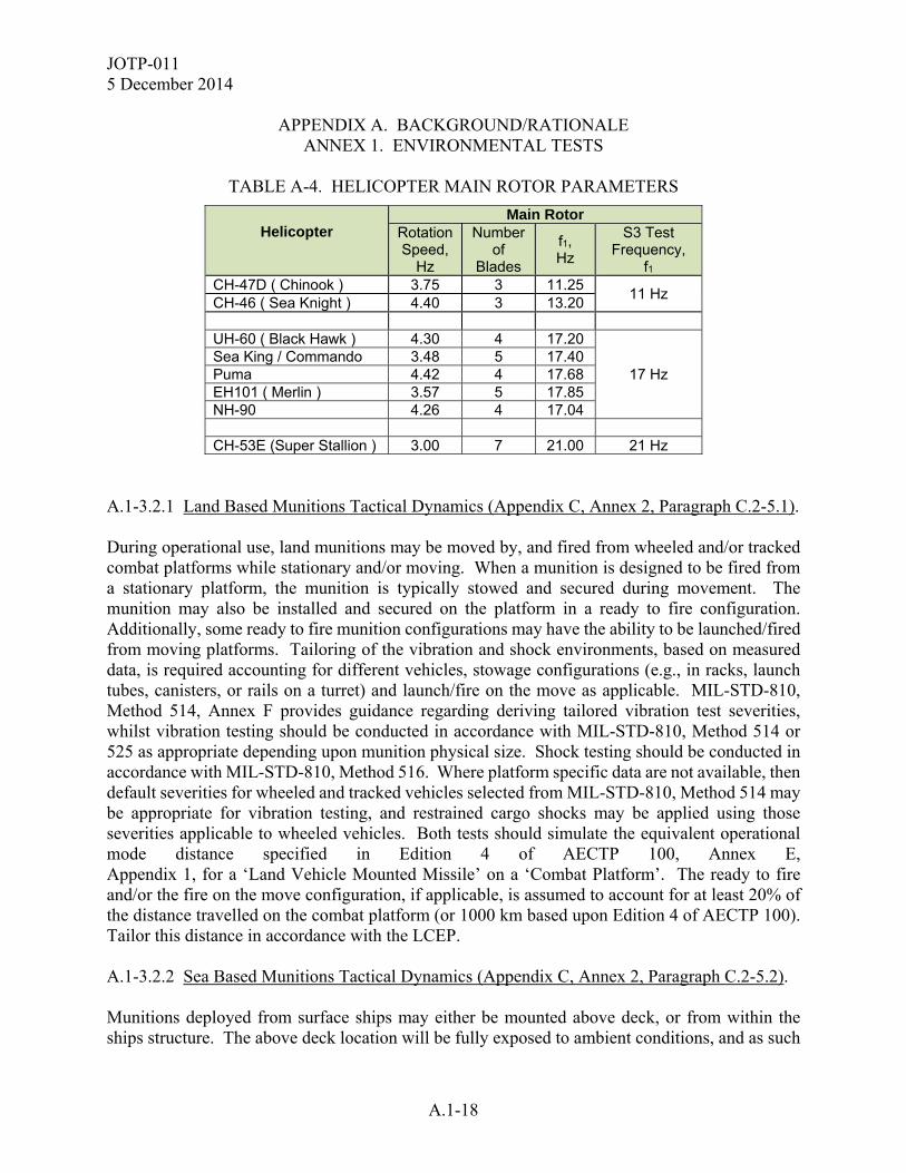
JOTP-011 5 December 2014
APPENDIX A. BACKGROUND/RATIONALE
ANNEX 1. ENVIRONMENTAL TESTS
A.1-18
TABLE A-4. HELICOPTER MAIN ROTOR PARAMETERS
Helicopter Main Rotor
Rotation Speed,
Hz
Number of
Blades
f1, Hz
S3 Test Frequency,
f1 CH-47D ( Chinook ) 3.75 3 11.25
11 Hz CH-46 ( Sea Knight ) 4.40 3 13.20 UH-60 ( Black Hawk ) 4.30 4 17.20
17 Hz Sea King / Commando 3.48 5 17.40 Puma 4.42 4 17.68 EH101 ( Merlin ) 3.57 5 17.85 NH-90 4.26 4 17.04 CH-53E (Super Stallion ) 3.00 7 21.00 21 Hz
A.1-3.2.1 Land Based Munitions Tactical Dynamics (Appendix C, Annex 2, Paragraph C.2-5.1). During operational use, land munitions may be moved by, and fired from wheeled and/or tracked combat platforms while stationary and/or moving. When a munition is designed to be fired from a stationary platform, the munition is typically stowed and secured during movement. The munition may also be installed and secured on the platform in a ready to fire configuration. Additionally, some ready to fire munition configurations may have the ability to be launched/fired from moving platforms. Tailoring of the vibration and shock environments, based on measured data, is required accounting for different vehicles, stowage configurations (e.g., in racks, launch tubes, canisters, or rails on a turret) and launch/fire on the move as applicable. MIL-STD-810, Method 514, Annex F provides guidance regarding deriving tailored vibration test severities, whilst vibration testing should be conducted in accordance with MIL-STD-810, Method 514 or 525 as appropriate depending upon munition physical size. Shock testing should be conducted in accordance with MIL-STD-810, Method 516. Where platform specific data are not available, then default severities for wheeled and tracked vehicles selected from MIL-STD-810, Method 514 may be appropriate for vibration testing, and restrained cargo shocks may be applied using those severities applicable to wheeled vehicles. Both tests should simulate the equivalent operational mode distance specified in Edition 4 of AECTP 100, Annex E, Appendix 1, for a ‘Land Vehicle Mounted Missile’ on a ‘Combat Platform’. The ready to fire and/or the fire on the move configuration, if applicable, is assumed to account for at least 20% of the distance travelled on the combat platform (or 1000 km based upon Edition 4 of AECTP 100). Tailor this distance in accordance with the LCEP. A.1-3.2.2 Sea Based Munitions Tactical Dynamics (Appendix C, Annex 2, Paragraph C.2-5.2). Munitions deployed from surface ships may either be mounted above deck, or from within the ships structure. The above deck location will be fully exposed to ambient conditions, and as such

JOTP-011 5 December 2014
APPENDIX A. BACKGROUND/RATIONALE ANNEX 1. ENVIRONMENTAL TESTS
A.1-19
will be subject to wave action in high seas that may directly impart shock loadings (‘sea slamming’) on the munitions in their launcher. Munitions located within the ship’s structure, such as in a vertical launch silo, are better protected and less likely to experience these shocks. Both configurations are likely to receive accelerations from sea slamming in high seas although sea slamming is unlikely to be a consideration for submarines operating below the surface. Due to the difficulty of replicating this environment, sea slamming is addressed with a structural analysis. Tailoring of the vibration and shock environment based on measured data is recommended although MIL-STD-810, Method 514, Annex D gives generic default vibration spectra. No life equivalence is assigned to this test but a duration of one hour per axis has been applied historically. MIL-STD-810, Method 514 does not contain a default test severity for submarines and is not normally required due to the benign nature of the environment. UNDEX shock is covered in paragraph A.1-3.1.2.2.2. A.1-3.2.3 Adjacent Munition Firing Shocks (Appendix C, Annex 2, Paragraph C.2-5.1.6). When munitions are fired, they release energy (thermal, acoustic and shock) into the surrounding environment. Consideration should be given to the effects of this energy impinging upon adjacent munitions, particularly launch shocks in multi-munition launcher/pod/silo configurations. Launch shock levels should be derived from data measured from adjacent munitions, applying the worst measured shocks using shock response spectra (MIL-STD-810 Method 516) and/or time waveform replication methods. The number of shocks to be applied should be based upon the frequency of the launch environment and quantity of adjacent munitions. A.1-3.2.4 Tactical Drop/Impact (Appendix C, Annex 2, Paragraph C.2-6). The Tactical Drop test simulates accidental drops encountered during handling of munitions when subjected to maintenance and/or (un)loading on the launch platform. For the latter, the munition will be in it launch configuration such as bare munition or canistered as described in paragraph 6.4 of the main text. The drop heights used are tailored according to the LCEP, but it is recommended that these should be no less than 1.5 m for munitions that can be readily manhandled without lifting equipment and tailored for those that cannot. The munition should remain safe to fire after dropping. It is not expected that the munition would be dropped more than once during its service life so only one drop test is considered necessary per orientation. Drop heights may be tailored taking due account of the fragility of the munition, with the tailoring rationale being documented in the S3 Safety Data Package; and the reduced drop height limitation documented in the Field Maintenance/Technical Manuals to require removal of the munition from service if dropped higher than the test heights.

JOTP-011 5 December 2014
APPENDIX A. BACKGROUND/RATIONALE
ANNEX 1. ENVIRONMENTAL TESTS
A.1-20
A.1-3.3 Rough Handling/Loading Drop (Appendix C, Annex 2, Paragraph C.2-7). Rough Handling Drop tests verify that the munition will be safe to dispose if dropped during loading onto the Combat Platform. Typical (historical) drop height values have ranged from 2.1 to 3 m. Tailor the drop height according to the LCEP. Due to the severity and accidental nature of this test environment, it is recommended that only one asset from each temperature condition be exposed to one drop while in its worst case orientation. If a munition subjected to this test is damaged to such an extent that it cannot be fired but the damage does not create a hazardous condition (i.e., safe to transport and disassemble after testing), then the assets may be re-purposed for additional testing such as BTCA or static fire testing. A.1-3.4 Low Velocity Parachute Drop (Appendix C, Annex 2, Paragraph C.2-8). Land based munitions are likely to be re-supplied by parachute delivery and are expected to remain S3 following such an event. Per MIL-STD-331, Test E5, low velocity parachute delivery typically result in impact velocities of 8.7 m/s (28.5 ft/sec). Due to variations in parachute delivery systems throughout NATO service and potential variation of drop conditions (wind speed, angle, etc.), an elevated velocity of 12.5 m/s (41 ft/sec) should be applied. This environment is commonly replicated by an 8 m freefall drop unless specific and validated evidence is presented to the contrary. If it can be demonstrated that the shock loads to the munition in parachute drop are less severe in terms of velocity and spectral content to the 2.1 m rough handling transit drop, the parachute drop may be eliminated as a S3 test requirement. This test environment is not applicable to sea based munitions. A.1-3.5 12-Meter Logistic Drop (Appendix C, Annex 2, Paragraph C.2-9). This mandatory logistic drop test, as described in MIL-STD-2105, assesses the safety of the weapon when exposed to a free-fall drop which may be encountered during ship loading operations. This test is conducted as a non-sequential test since it is representing an accident scenario with no expectation for the munition to remain safe for use. The 12-meter logistic safety drop test is required in the unpackaged configuration for any munition handled out of the shipping container on a naval vessel. In most cases, the munition will be tested in the packaged configuration. For either configuration, the drop height of 12-meters should not be tailored. A.1-3.6 Munition Flight Dynamics (Appendix C, Annex 2, Paragraph C.2-10). Surface launched missiles and rockets may experience high shock levels during rocket motor ignition and significant vibration levels during free flight. Appropriate functional tests may be conducted during these environments to ensure all safety critical components are functional at the system level. These tests are not required for the Empirical S3 test flow for which these environments will be evaluated through dynamic firings.
JOTP-011 5 December 2014
APPENDIX A. BACKGROUND/RATIONALE ANNEX 1. ENVIRONMENTAL TESTS
A.1-21
A.1-3.6.1 Launch Shock (Appendix C, Annex 2, Paragraph C.2-10.1). Launch shock should be conducted in accordance with MIL-STD-810, Methods 516 and 525 as appropriate; however, tailored test levels based on measured data will normally be used. Test severities should be derived in accordance with MIL-STD-810, Method 514, Annex F. A.1-3.6.2 Free Flight Vibration (Appendix C, Annex 2, Paragraph C.2-10.2). Free flight vibration testing should be conducted in accordance with MIL-STD-810, Methods 514 and 525 as appropriate; however, tailored test levels based on measured data will normally be used. Test severities should be derived in accordance with MIL-STD-810, Method 514, Annex F.

JOTP-011 5 December 2014
APPENDIX A. BACKGROUND/RATIONALE ANNEX 1. ENVIRONMENTAL TESTS
A.1-22
(This page is intentionally blank.)
JOTP-011 5 December 2014
APPENDIX A. BACKGROUND/RATIONALE ANNEX 2. OPERATING TESTS
A.2-1
A.2-1 FIRING SAFETY TESTS (APPENDIX D, ANNEX 1). Firing tests are conducted to determine firing safety related to munition operation, launch, and flight. These tests are conducted at both high and low temperature conditions. The high temperature tests should be conducted at the higher of 63 °C or the SRE temperature. The cold temperature tests should be conducted at -46 °C. Although these values may be more severe than the manufacturer’s recommended upper and lower firing temperatures for munition performance, the extreme values should be used to assess safety aspects of the motor firing under worst case service conditions. Appropriate precautions should be taken if the firing temperature exceeds the manufacturer recommendations. A.2-1.1 Dynamic Firing (Appendix D, Annex 1, Paragraph D.1-1). The dynamic firing tests are conducted from unmanned ground launch stations on an instrumented firing range to demonstrate that the munition: is safe to launch (does not eject hazardous debris or detonate upon ignition), safely separates from the launch point/tube, and travels at and explosively functions at trajectories which cause no additional hazards to the platform or firing crew. Collect the following data, as applicable, in support of the dynamic firing test objectives. a. The data acquired during firing should be sufficient to support weapon danger area analysis and to capture any performance data that may be related to safety b. Acoustic noise, blast overpressure, toxic gases, thermal effects, and radiance, data are potential health hazards that may cause harm to the launch platform or personnel. Other system specific health hazards should be considered. See Appendix H, Annex 2. c. Evidence is collected regarding rocket motor safety and initiation system functioning. d. Verification of safe separation distance may be obtained from dynamic firings; if needed, additional evidence may be obtained from component level sled tests (with fuze and warhead) or from additional fuze arming distance firings in accordance with Appendix D, Annex 1, paragraph D.1-2. For munitions that are expected to penetrate light brush or other obstructions in close proximity to the launch platform, additional fuze sensitivity tests in accordance with Appendix D, Annex 1, paragraph D.1-3 should be considered. e. Collect launch shock data, if required. f. Collect launch blast debris data (i.e., dispersement pattern, velocity, size, mass) and launcher reaction data to define the space that is unsafe for occupancy during firings.
JOTP-011 5 December 2014
APPENDIX A. BACKGROUND/RATIONALE
ANNEX 2. OPERATING TESTS
A.2-2
A.2-2 COMPONENT LEVEL TESTS (APPENDIX D, ANNEX 2) A.2-2.1 Rocket Motor Tests. Static firing and case burst tests are performed to determine the probability of catastrophic motor case rupture during firing operations. All munitions must have been subjected to extreme environmental stresses, such that the characteristic variation of the rocket motor pressure data can be obtained during the static firing and burst tests. A.2-2.1.1 Static Firing (Appendix D, Annex 2, Paragraph D.2-1). These tests are performed to measure maximum internal operating pressures and provide data to determine any changes of motor burn performance that may result from environmental exposure. To induce the maximum operating pressure, and to assess thermal liner/bond line integrity, the rocket motors are static fired under both high and low temperature conditions. The high temperature tests should be conducted at 63 °C or the unpackaged SRE. The cold temperature tests should be conducted at -46 °C. Although these values may be more severe than the manufacturers recommended upper and lower firing temperatures for munition performance, the extreme values should be used to assess safety aspects of the motor firing under worst case service conditions. Appropriate precautions should be taken if the firing temperature exceeds the manufacturer recommendations. A.2-2.1.2 Burst (Appendix D, Annex 2, Paragraph D.2-2). Burst tests are performed to measure the internal pressure required to burst the rocket motor. Characterization of the effects of the bursting motor is a secondary objective. Hydrostatic burst testing is the most commonly used test method and may be conducted with or without propellant. Evidence of motor case structural integrity should be obtained from factory fresh motor case burst testing and from environmentally stressed motor case burst testing to determined the susceptibility of the case material and seals to degradation as a result of sequential environmental testing. A.2-2.2 Other Pressure Vessels (Appendix D, Annex 2, Paragraph D.2-3). Appropriate burst tests should be conducted on any other pressure vessel in the munition following sequential environmental testing. This may be accomplished either through component level operational tests in the Analytical Flow or firing safety tests in the Empirical Flow. A.2-2.3 Warhead Arena Trials (Appendix D, Annex 2, Paragraph D.2-4). The safe separation distance is determined by the warhead fragment characteristics (size, mass, velocity, and spatial dispersion). A sample size of at least four is required because only a portion of the total number of fragments produced is collected in the recovery medium. The sample size must be large enough to reliably evaluate fragmentation characteristics in order to determine the
JOTP-011 5 December 2014
APPENDIX A. BACKGROUND/RATIONALE ANNEX 2. OPERATING TESTS
A.2-3
average fragmentation spatial dispersion. Note that data from this test are also used to determine range safety parameters (i.e., Weapon Danger Area or "Safety Fan"). This test is conducted on factory fresh assets in order to obtain the maximum fragmentation distance. A.2-2.4 Other Energetics (Appendix D, Annex 2, Paragraph D.2-5). Appropriate functional testing should be conducted on any other energetic in the munition following sequential environmental testing. This may be accomplished either through component level operational tests in the Analytical Flow or firing safety tests in the Empirical Flow. A.2-2.5 Other Safety Critical Components (Appendix D, Annex 2, Paragraph D.2-6). Although energetic and pressure vessel components account for most direct safety risks during the transportation, handling, and operation of a surface and underwater launched munition, other components may contribute to unsafe conditions upon launch. If it is determined that a safety critical component is susceptible to environmental degradation, operation of the component should be evaluated following sequential environmental testing either through component level operational tests in the Analytical Flow or firing safety tests in the Empirical Flow. Note that the operational tests are only required to identify potentially unsafe operation and not intended to evaluate the full performance characteristics of the components.

JOTP-011 5 December 2014
APPENDIX A. BACKGROUND/RATIONALE ANNEX 2. OPERATING TESTS
A.2-4
(This page is intentionally blank.)
JOTP-011 5 December 2014
APPENDIX A. BACKGROUND/RATIONALE ANNEX 3. NON-SEQUENTIAL SAFETY TESTS
A.3-1
A.3-1 ELECTROMAGNETIC ENVIRONMENTAL EFFECTS (E3) ASSESSMENT AND TESTING (APPENDIX H, ANNEX 1). The following E3 effects should be considered to assess the safety of the weapon when exposed to the environment which may be encountered during the weapon system stockpile to safe separation sequence (transportation/storage, assembly/disassembly, staged, loading/unloading, platform-loaded, and immediate post-launch). Levels should encompass sea, land, and aviation storage, usage, maintenance, and shipment requirements as identified in the LCEP. A.3-1.1 HERO (Appendix H, Annex 1, Paragraph H.1-1). This test assesses the safety of the weapon at a system level by exposing the weapon and its associated platform(s) to its operational electromagnetic environments and monitors the response of the weapons Electrically Initiated Devices (EIDs also known as Electro-explosive Devices (EEDs)) or Electronic Safe and Arming Devices (ESADs) and associated firing circuits when exposed. A.3-1.2 ESD (Appendix H, Annex 1, Paragraph H.1-2). These tests assess the safety of the weapon when exposed to ESD phenomenon such as those encountered during handling and helicopter transport. Test asset quantities should be based on MIL-STD-331. A.3-1.3 Lightning Hazard (Appendix H, Annex 1, Paragraph H.1-3). These tests assess the safety of the weapon when exposed to near and direct strike lightning, which may occur during logistic and field operations. A.3-1.4 Electromagnetic Compatibility (Appendix H, Annex 1, Paragraph H.1-4). Electromagnetic Compatibility (EMC) tests assess the suitability of the weapon to operate within the electromagnetic environment for which they are designed to be used. These tests are performed on a powered weapon during simulated normal operation and are designed to assess to what extent the weapon not only is affected by the electromagnetic environment in which it is expected to operate but also its electromagnetic effect on other electrical systems it interacts with or is in close proximity to (e.g., on the same platform). Much of this testing is for reliability purposes however some EMC tests provide safety assurance, for example those designed to monitor for interference carried into the weapon via physical electrical interfaces which may affect the performance of EID and/or ESAD firing circuits.
JOTP-011 5 December 2014
APPENDIX A. BACKGROUND/RATIONALE
ANNEX 3. NON-SEQUENTIAL SAFETY TESTS
A.3-2
A.3-2 HEALTH HAZARDS (APPENDIX H, ANNEX 2). Health hazard data is to be collected during the firing safety tests (see Appendix D, Annex 1). The hazards to be assessed for surface launched munitions are described below. A.3-2.1 Acoustic Energy (Impulse Noise and Blast Overpressure) (Appendix H, Annex 2, Paragraph H.2-1). The weapon firing precipitates the sudden release of gases into the surrounding air, causing a shock wave or front to be propagated outward from the source. Firing tests are performed to measure blast overpressure and acoustic noise to determine if the shock wave damages structures and/or injures personnel. Further information may be found in MIL-STD-1474 and International Standard ISO 10843: 1997 Acoustics - Methods for the description and physical measurement of single impulses or series of impulses. A.3-2.2 Toxic Chemical Substances (Appendix H, Annex 2, Paragraph H.2-2). Rocket exhaust gases contain toxic chemical substances such as CO, CO2, SO2, NO, NO2, and HCl. Other harmful chemicals should be considered if determined to be potentially harmful to the operator. These hazards shall be evaluated with respect to the envisaged operational environment and on the basis of pertinent national laws and regulations. A.3-2.3 Radiating Energy (Appendix H, Annex 2, Paragraph H.2-3). Weapon firings may subject the operator to extreme heat and light exposure. The propulsion unit radiance may produce permanent or temporary eye damage (i.e., flash blindness). Exposure to heat during munition launch may cause eye and skin damage. A.3-2.4 Launch Shock (Recoil) (Appendix H, Annex 2, Paragraph H.2-4). Shock levels due to weapon firing and recoil may injure the firing crew. The probability of injury increases with the blast energy of the weapon, proximity of the operator to the weapon, and the duration of the shock environment. A.3-2.5 Other Launch Platform Integration Assessments. Sufficient evidence should be provided to determine whether the launch platform interface and the munition have adequate structural integrity to withstand the anticipated dynamic loading. For munition systems following the Analytical S3 Test Approach (see Appendix B, Annex 1), live fire testing from ground launch stations may be required to provide sufficient evidence of safe separation, launch/blast effects, and human factors associated with weapon system operation.
JOTP-011 5 December 2014
APPENDIX B. TEST PROGRAM FOR SURFACE AND UNDERWATER LAUNCHED MUNITIONS
B-1
This document was developed within the international community and is written with references to both US and NATO test procedures to provide a framework for international procurement and test programs. Table I2-1 (Appendix I, Annex 2) provides cross reference of similar national and international test standards. This Appendix provides the overall S3 test programs for surface and underwater launched munitions. Each test program is presented in the form of test flowcharts, munition allocation tables, and test asset quantity tables. It should be noted that several non-sequential test requirements (i.e., hazard classification and insensitive munitions tests) are considered part of the overall S3 program, but are not governed by this document. For these tests, references are provided for determination of test requirements and quantities. See Chapter 8 of this document for the general description and intended application of the test flow options presented in this Appendix.

JOTP-011 5 December 2014
APPENDIX B. TEST PROGRAM FOR SURFACE AND UNDERWATER LAUNCHED MUNITIONS
B-2
(This page is intentionally blank.)
JOTP-011 5 December 2014
APPENDIX B. TEST PROGRAM FOR SURFACE AND UNDERWATER LAUNCHED MUNITIONS
ANNEX 1. ANALYTICAL S3 TEST PROGRAM
B.1-1
S3 assessment testing of surface and underwater launched munitions requires a series of sequential environmental tests followed by BTCA, component level operating/firing tests, and non-sequential (stand alone) environmental tests. The overall munition quantities for the sequential and non-sequential tests are provided in Table B1-1. The Analytical S3 Test Program is illustrated in the form of test flowcharts in Figures B1-1 and B1-2 coupled with the munition allocation Table B1-2 which provides the test flow for each individual munition. Test asset quantities may be tailored in accordance with the guidelines in paragraph 6.8. B.1-1 SAMPLE QUANTITIES FOR SEQUENTIAL ENVIRONMENTAL TESTS USING THE ANALYTICAL S3 TEST APPROACH. A total of 20 live munitions and 10 inert motor cases are to be subjected to sequential environmental tests. The live munitions may contain mass simulants to replace components that are unrelated to the munition safety (e.g., guidance, control). Configurations may vary according to particular test objectives. Upon completion of the environmental tests, the test assets are divided into three groups and tested further as follows: a. Four munitions are subjected to additional climatic tests and then disassembled for BTCA. Two of the BTCA test assets may be derived from the rough handling test rounds, assuming the munition successfully survives the drop. Plan for two extra assets if the rounds cannot be used in additional testing. b. Ten munitions are disassembled for component level testing. The following component level tests will be required: (1) Ten rocket motors are statically fired. (2) Any other pressure vessel (excluding rocket motor cases) which may cause serious personnel hazards must be burst tested. A minimum of ten of each type are required to determine the safety design margin. (3) Any other energetic devices (e.g., igniters, initiators, squibs, pyrotechnics, and thermal batteries) which may cause serious personnel hazards at the system level must be static fired. A minimum of ten of each type are required to determine the safety design margin. c. Four munitions are dynamically fired as complete rounds to demonstrate safe egress from the launch canister. This number may be reduced to two firings for single munition launch canisters. The dynamic firings may be eliminated if there is no concern for munition egress from the canister. d. Ten rocket motor cases are hydrostatically burst tested.

JOTP-011 5 December 2014
APPENDIX B. TEST PROGRAM FOR SURFACE AND UNDERWATER
LAUNCHED MUNITIONS ANNEX 1. ANALYTICAL S3 TEST PROGRAM
B.1-2
B.1-2 SAMPLE QUANTITIES FOR NON-SEQUENTIAL SAFETY TESTS USING THE ANALYTICAL S3 TEST APPROACH. A minimum of 66 test assets including 5 live munitions, 4 inert munitions, 4 warheads, and 53 sets of EID/ESAD’s will be required for the following non-sequential safety tests: a. Three (3) live munitions for 12-meter Logistic Drop. b. One (1) live munition for Shipboard UNDEX Safety Shock. c. One (1) live and three (3) inert munitions for use with 53 ea EID/ESADs required for Electromagnetic Environmental Effects (E3) assessment tests. Instrumented components may be substituted where actual measurement of the maximum no-fire stimulus may be obtained. Systems or subsystems incorporating ESAD's must be tested while in the functional mode. At a minimum, E3 assessment tests will include the following: (1) One (1) live munition and one (1) inert munition with 20 live sets of EID/ESAD’s for Lightning Hazard. (2) One (1) inert munition with one instrumented set of EID/ESAD for HERO and EMC tests. (3) One (1) inert munition with 32 live sets of EID/ESAD’s for ESD tests. d. One (1) inert underwater munition for pressurization testing. e. Additional inert munitions may be required for Operational and Maintenance Review as described in Appendix H, Annex 3. f. Additional live munitions will be required for Hazard Classification Testing per TB 700-2. g. Additional munitions will be required for Insensitive Munitions Tests per MIL-STD-2105, STANAG 4439 and AOP-39. h. Four modified munitions will be required for Warhead Arena Trials. i. Systems or subsystems incorporating firing circuits controlled by electronics must be tested while in the functional mode if the threat is present when they are powered. j. Additional test assets may be required for fuze S3 testing per MIL-STD-331.
JOTP-011 5 December 2014
APPENDIX B. TEST PROGRAM FOR SURFACE AND UNDERWATER LAUNCHED MUNITIONS
ANNEX 1. ANALYTICAL S3 TEST PROGRAM
B.1-3
k. Additional test assets may be required for other safety tests determined to be necessary to address special circumstances not considered in this document or as the result of marginal or inconclusive test results throughout the overall S3 test program.
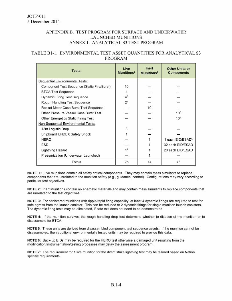
JOTP-011 5 December 2014
APPENDIX B. TEST PROGRAM FOR SURFACE AND UNDERWATER
LAUNCHED MUNITIONS ANNEX 1. ANALYTICAL S3 TEST PROGRAM
B.1-4
TABLE B1-1. ENVIRONMENTAL TEST ASSET QUANTITIES FOR ANALYTICAL S3 PROGRAM
Tests
Live Munitions1
Inert Munitions2
Other Units or Components
Sequential Environmental Tests:
Component Test Sequence (Static Fire/Burst)
BTCA Test Sequence
Dynamic Firing Test Sequence
Rough Handling Test Sequence
Rocket Motor Case Burst Test Sequence
Other Pressure Vessel Case Burst Test
Other Energetics Static Firing Test
Non-Sequential Environmental Tests:
12m Logistic Drop
Shipboard UNDEX Safety Shock
HERO
ESD
Lightning Hazard
Pressurization (Underwater Launched)
10
4
43
24
---
---
---
3
1
---
---
17
---
---
---
---
---
10
---
---
---
---
1
1
1
1
---
---
---
---
---
105
105
---
---
1 each EID/ESAD6
32 each EID/ESAD
20 each EID/ESAD
---
Totals 25 14 73
NOTE 1: Live munitions contain all safety critical components. They may contain mass simulants to replace components that are unrelated to the munition safety (e.g., guidance, control). Configurations may vary according to particular test objectives. NOTE 2: Inert Munitions contain no energetic materials and may contain mass simulants to replace components that are unrelated to the test objectives. NOTE 3: For canistered munitions with ripple/rapid firing capability, at least 4 dynamic firings are required to test for safe egress from the launch canister. This can be reduced to 2 dynamic firings for single munition launch canisters. The dynamic firing tests may be eliminated, if safe exit does not need to be demonstrated. NOTE 4: If the munition survives the rough handling drop test determine whether to dispose of the munition or to disassemble for BTCA. NOTE 5: These units are derived from disassembled component test sequence assets. If the munition cannot be disassembled, then additional environmentally tested units may be required to provide this data. NOTE 6: Back-up EIDs may be required for the HERO test otherwise a damaged unit resulting from the modification/instrumentation/testing processes may delay the assessment program. NOTE 7: The requirement for 1 live munition for the direct strike lightning test may be tailored based on Nation specific requirements.
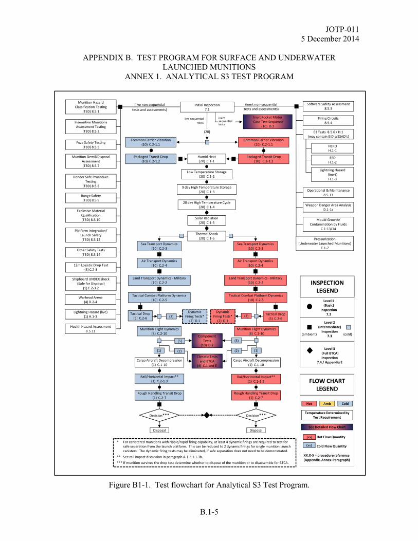
JOTP-011 5 December 2014
APPENDIX B. TEST PROGRAM FOR SURFACE AND UNDERWATER LAUNCHED MUNITIONS
ANNEX 1. ANALYTICAL S3 TEST PROGRAM
B.1-5
Figure B1-1. Test flowchart for Analytical S3 Test Program.
Solar Radiation (20) C.1‐5
Component Tests
(10) D.2
Climatic Tests and BTCA
(4) C.1 and E
9 day High Temperature Storage (20) C.1‐3
28 day High Temperature Cycle (20) C.1‐4
Low Temperature Storage (20) C.1‐2
Thermal Shock (20) C.1‐6
(inert non‐sequential tests and assessments)
(live non‐sequential
tests and assessments)
Humid Heat(20) C.1‐1
Rough Handling Transit Drop(1) C.2‐7
Tactical Combat Platform Dynamics (10) C.2‐5
Common Carrier Vibration (10) C.2‐1.1
Air Transport Dynamics (10) C.2‐4
Packaged Transit Drop (10) C.2‐1.2
(5)
Rough Handling Transit Drop (1) C.2‐7
Tactical Combat Platform Dynamics(10) C.2‐5
(2)
Air Transport Dynamics (10) C.2‐4
Common Carrier Vibration (10) C.2‐1.1
Sea Transport Dynamics (10) C.2‐3
Rail/Horizontal Impact** (1) C.2‐1.3
Packaged Transit Drop (10) C.2‐1.2
live sequential tests
(20)
Inert Rocket MotorCase Test Sequence
(10) D.2
inert sequential tests
Land Transport Dynamics ‐Military(10) C.2‐2
Rail/Horizontal Impact** (1) C.2‐1.3
Sea Transport Dynamics (10) C.2‐3
Land Transport Dynamics ‐Military (10) C.2‐2
Level 1 (Basic)
Inspection 7.2
Level 2 (Intermediate) Inspection
7.3
Level 3(Full BTCA) Inspection
7.4 / Appendix E
(ambient) (cold)
INSPECTION LEGEND
See Detailed Flow Chart
Hot Flow Quantity
Cold Flow Quantity
XX.X‐X = procedure reference (Appendix. Annex‐Paragraph)
FLOW CHART LEGEND
Temperature Determined by Test Requirement
Hot
(xx)
Cold
(xx)
Amb
* For canistered munitions with ripple/rapid firing capability, at least 4 dynamic firings are required to test for safe separation from the launch platform. This can be reduced to 2 dynamic firings for single munition launch canisters. The dynamic firing tests may be eliminated, if safe separation does not need to be demonstrated.
** See rail impact discussion in paragraph A.1‐3.1.1.3b.
*** If munition survives the drop test determine whether to dispose of the munition or to disassemble for BTCA.
Initial Inspection 7.1
Decision***
Disposal
Decision***
Disposal
Cargo Aircraft Decompression(1) C.1‐10
Cargo Aircraft Decompression(1) C.1‐10
Munition Hazard Classification Testing
(TBD) 8.5.1
Lightning Hazard (live) (1) H.1‐3
12m Logistic Drop Test(3) C.2‐8
Other Safety Tests(TBD) 8.5.14
Insensitive Munitions Assessment Testing
(TBD) 8.5.2
Warhead Arena (4) D.2‐4
Munition Demil/DisposalAssessment(TBD) 8.5.7
Range Safety(TBD) 8.5.9
Explosive Material Qualification(TBD) 8.5.10
Fuze Safety Testing(TBD) 8.5.5
Render Safe Procedure Testing
(TBD) 8.5.8
Platform Integration/Launch Safety(TBD) 8.5.12
Shipboard UNDEX Shock(Safe for Disposal)
(1) C.2‐3.2
Firing Circuits8.5.4
Weapon Danger Area AnalysisD.1‐1c
Operational & Maintenance8.5.13
Software Safety Assessment8.5.3
Mould Growth/Contamination by Fluids
C.1‐13/14
E3 Tests 8.5.6 / H.1(may contain EID’s/ESAD’s)
HEROH.1‐1
ESDH.1‐2
Lightning Hazard (inert) H.1‐3
Pressurization (Underwater Launched Munitions)
C.1‐7
Munition Flight Dynamics (8) C.2‐10
Tactical Drop(5) C.2‐6
(1)
Dynamic Firing Tests*
(2) D.1(2)
(5)
(2)
Munition Flight Dynamics (8) C.2‐10
Tactical Drop(5) C.2‐6
(1)
(2)Dynamic
Firing Tests*(2) D.1
Health Hazard Assessment8.5.11
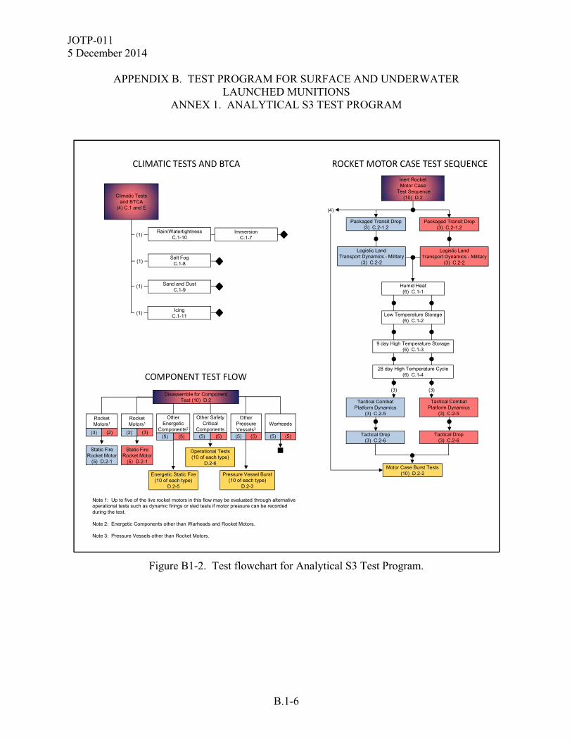
JOTP-011 5 December 2014
APPENDIX B. TEST PROGRAM FOR SURFACE AND UNDERWATER
LAUNCHED MUNITIONS ANNEX 1. ANALYTICAL S3 TEST PROGRAM
B.1-6
Figure B1-2. Test flowchart for Analytical S3 Test Program.
CLIMATIC TESTS AND BTCA
Sand and DustC.1-9
Rain/WatertightnessC.1-10
Salt FogC.1-8
ImmersionC.1-7
Climatic Tests and BTCA
(4) C.1 and E
(1)
(1)
(1)
(1)Icing
C.1-11
ROCKET MOTOR CASE TEST SEQUENCE
Note 1: Up to five of the live rocket motors in this flow may be evaluated through alternative operational tests such as dynamic firings or sled tests if motor pressure can be recorded during the test.
Note 2: Energetic Components other than Warheads and Rocket Motors.
Note 3: Pressure Vessels other than Rocket Motors.
Pressure Vessel Burst(10 of each type)
D.2-3
Energetic Static Fire(10 of each type)
D.2-5
Operational Tests(10 of each type)
D.2-6
Static Fire Rocket Motor
(5) D.2-1
Static Fire Rocket Motor
(5) D.2-1
Other Energetic
Components2
(5)(5)
Other Safety Critical
Components(5)(5)
Other Pressure Vessels3
(5)(5)
Rocket Motors1
(3)(2)
Rocket Motors1
(2)(3)
Warheads
(5)(5)
Disassemble for Component Test (10) D.2
COMPONENT TEST FLOW
Motor Case Burst Tests(10) D.2-2
9 day High Temperature Storage (6) C.1-3
28 day High Temperature Cycle (6) C.1-4
Low Temperature Storage (6) C.1-2
Packaged Transit Drop (3) C.2-1.2
Logistic Land Transport Dynamics - Military
(3) C.2-2
Tactical Combat Platform Dynamics
(3) C.2-5
Tactical Combat Platform Dynamics
(3) C.2-5
(3)(3)
Humid Heat (6) C.1-1
(4)
Inert Rocket Motor Case
Test Sequence(10) D.2
Packaged Transit Drop (3) C.2-1.2
Logistic Land Transport Dynamics - Military
(3) C.2-2
Tactical Drop(3) C.2-6
Tactical Drop(3) C.2-6

JOTP-011 5 December 2014
APPENDIX B. TEST PROGRAM FOR SURFACE AND UNDERWATER LAUNCHED MUNITIONS ANNEX 1. ANALYTICAL S3 TEST PROGRAM
B.1-7
TABLE B1-2. SEQUENTIAL TEST ROUND ALLOCATION TABLE FOR THE S3 ANALYTICAL TEST PROGRAM
Test serial App/Annex/Para 1 2 3 4 5 6 7 8 9 10 11 12 13 14 15 16 17 18 19 20 1 2 3 4 5 6 7 8 9 10 Level 2 Inspection (BIT, visual, NDT, radiography) 7.3 c c c c c c c c c c c c c c c c c c c c a a a a a aCommon carrier vibration C/2/1.1 h h h h h h h h h h c c c c c c c c c cPackaged transit drop C/3/1 h h h h h h h h h h c c c c c c c c c c h h h c c c Level 2 Inspection (BIT, visual, NDT, radiography) 7.3 a a a a a a a a a a a a a a a a a a a a a a a a a aHumid heat C/1/1 x x x x x x x x x x x x x x x x x x x x x x x x x xLow temperature storage C/1/2 x x x x x x x x x x x x x x x x x x x x x x x x x xHigh temperature storage C/1/3 x x x x x x x x x x x x x x x x x x x x x x x x x xHigh temperature cycling C/1/4 x x x x x x x x x x x x x x x x x x x x x x x x x xSolar radiation C/1/5 x x x x x x x x x x x x x x x x x x x xThermal shock C/1/6 x x x x x x x x x x x x x x x x x x x x Level 2 Inspection (BIT, visual, NDT, radiography) 7.3 c c c c c c c c c c c c c c c c c c c c a a a a a aSea Transport Dynamics C/2/3 h h h h h h h h h h c c c c c c c c c c Level 2 Inspection (BIT, visual, NDT, radiography) 7.3 a a a a a a a a a a a a a a a a a a a aAir Transport Dynamics - Military C/2/4 h h h h h h h h h h c c c c c c c c c c h h h c c c Level 2 Inspection (BIT, visual, NDT, radiography) 7.3 a a a a a a a a a a a a a a a a a a a a a a a a a aLand Transport Dynamics - Military C/2/2 h h h h h h h h h h c c c c c c c c c c Level 2 Inspection (BIT, visual, NDT, radiography) 7.3 a a a a a a a a a a a a a a a a a a a aTactical Combat Platform Dynamics C/2/5 h h h h h h h h h h c c c c c c c c c c h h h c c c Level 2 Inspection (BIT, visual, NDT, radiography) 7.3 a a a a a a a a c a a a a a a a a a c a a a a a a aTactical Drop C/2/6 h h h h h c c c c c h h h c c c Level 2 Inspection (BIT, visual, NDT, radiography) 7.3 a a a a c a a a a c a a a a a aMunition Flight Dynamics C/2/10 h h h h h h h h c c c c c c c c Level 2 Inspection (BIT, visual, NDT, radiography) 7.3 c c c c c c c c c c c c c c c cCargo Aircraft Rapid Decompression C/1/12 a a Level 2 Inspection (BIT, visual, NDT, radiography) 7.3 a aRail Impact C/2/1.3 h c Level 2 Inspection (BIT, visual, NDT, radiography) 7.3 a aRough Handling Transit Drop** C/2/7 h c Level 2 Inspection (BIT, visual, NDT, radiography) 7.3 c cSalt fog C/1/8 xSand & dust C/1/9 xRain/watertightness C/1/10 xImmersion/Pressurization C/1/7 xIcing C/1/11 x Level 3 Inspection (Full BTCA) 7.4 a a a a a aDynamic Firing Tests* D/1/1 c c h hRocket motor static firing D/2/1 h c h c h c h c h cRocket motor burst D/2/2 a a a a a a a a a aOther pressure vessel burst integrity D/2/3 a a a a a a a a a aWarhead Level 2 Inspection (component level) 7.3 a a a a a a a a a aOther energetic static fire D/2/5 a a a a a a a a a aOther safety critical components operational D/2/6 a a a a a a a a a a
Munition number (Live Munitions) Motor Case Sequence (Inert)
* For canistered munitions with ripple/rapid firing capability, at least 4 dynamic firings are required to test for safe separation from the launch platform. This can be reduced to 2 dynamic firings for single munition launch canisters. The dynamic firing tests may be eliminated, if safe separation does not need to be demonstrated.** If munition survives the drop test determine whether to dispose of the munition or to disassemble for BTCA.
Key: a = ambient test c = cold conditioned test h = hot conditioned test x = test temperature defined in test

JOTP-011 5 December 2014
APPENDIX B. TEST PROGRAM FOR SURFACE AND UNDERWATER
LAUNCHED MUNITIONS ANNEX 1. ANALYTICAL S3 TEST PROGRAM
B.1-8
(This page is intentionally blank.)
JOTP-011 5 December 2014
APPENDIX B. TEST PROGRAM FOR SURFACE AND UNDERWATER LAUNCHED MUNITIONS
ANNEX 2. EMPIRICAL S3 TEST PROGRAM
B.2-1
S3 assessment testing of surface and underwater launched munitions requires a series of sequential environmental tests followed by BTCA, operating/firing tests, and non-sequential (stand alone) environmental tests. The overall munition quantities for the sequential and non-sequential tests are provided in Table B2-1. The Empirical S3 Test Program is illustrated in the form of test flowcharts in Figures B2-1 and B2-2 coupled with the munition allocation Table B2-2 which provides the sequential environmental test flow for each individual munition. Test asset quantities may be tailored in accordance with the guidelines in paragraph 6.8. B.2-1 SAMPLE QUANTITIES FOR SEQUENTIAL ENVIRONMENTAL TESTS USING THE EMPIRICAL S3 TEST APPROACH. A total of 36 live munitions and 10 inert motor cases are to be subjected to sequential environmental tests. The live munitions may contain mass simulants to replace components that are unrelated to the munition safety (e.g., guidance, control). Configurations may vary according to particular test objectives. Upon completion of the environmental tests, the test assets are divided into three groups and tested further as follows: a. Four live munitions are subjected to additional climatic tests and the reduced BTCA requirements selected from Appendix E. Two of the BTCA test assets may be derived from the rough handling test rounds, assuming the munition successfully survives the drop. Plan for two extra assets if the rounds cannot be used in additional testing. b. Rocket motors from ten munitions are static fired. c. Twenty munitions are fired as complete rounds. d. Ten inert motor cases are burst tested. B.2-2 SAMPLE QUANTITIES FOR NON-SEQUENTIAL TESTS USING THE EMPIRICAL S3 TEST APPROACH. A minimum of 66 test assets including 5 live munitions, 4 inert munitions, 4 warheads, and 53 sets of EID/ESAD’s will be required for the following non-sequential safety tests: a. Three (3) live munitions for 12-meter Logistic Drop. b. One (1) live munition for Shipboard UNDEX Safety Shock. c. One (1) live and three (3) inert munitions for use with 53 ea EID/ESADs required for Electromagnetic Environmental Effects (E3) assessment tests. Instrumented components may be substituted where actual measurement of the maximum no-fire stimulus may be obtained.
JOTP-011 5 December 2014
APPENDIX B. TEST PROGRAM FOR SURFACE AND UNDERWATER
LAUNCHED MUNITIONS ANNEX 2. EMPIRICAL S3 TEST PROGRAM
B.2-2
Systems or subsystems incorporating ESAD's must be tested while in the functional mode. At a minimum, E3 assessment tests will include the following: (1) One (1) live munition and 1 inert munition with 20 live sets of EID/ESAD’s for Lightning Hazard. (2) One (1) inert munition with one instrumented EID/ESAD for HERO tests. (3) One (1) inert munition with 32 live sets of EID/ESAD’s for ESD tests. d. One (1) inert underwater munition for pressurization testing. e. Additional inert munitions may be required for Operational and Maintenance Review as described in Appendix H, Annex 3. f. Additional live munitions will be required for Hazard Classification Testing per TB 700-2. g. Additional munitions will be required for Insensitive Munitions Tests per MIL-STD-2105, STANAG 4439 and AOP-39. h. Four modified munitions will be required for Warhead Arena Trials. i. Systems or subsystems incorporating firing circuits controlled by electronics must be tested while in the functional mode if the threat is present when they are powered. j. Additional test assets may be required for fuze S3 testing per MIL-STD-331. k. Additional test assets may be required for other safety tests determined to be necessary to address special circumstances not considered in this document or as the result of marginal or inconclusive test results throughout the overall S3 test program.
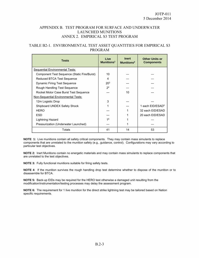
JOTP-011 5 December 2014
APPENDIX B. TEST PROGRAM FOR SURFACE AND UNDERWATER LAUNCHED MUNITIONS
ANNEX 2. EMPIRICAL S3 TEST PROGRAM
B.2-3
TABLE B2-1. ENVIRONMENTAL TEST ASSET QUANTITIES FOR EMPIRICAL S3 PROGRAM
Tests
Live Munitions1
Inert Munitions2
Other Units or Components
Sequential Environmental Tests:
Component Test Sequence (Static Fire/Burst)
Reduced BTCA Test Sequence
Dynamic Firing Test Sequence
Rough Handling Test Sequence
Rocket Motor Case Burst Test Sequence
Non-Sequential Environmental Tests:
12m Logistic Drop
Shipboard UNDEX Safety Shock
HERO
ESD
Lightning Hazard
Pressurization (Underwater Launched)
10
4
203
24
---
3
1
---
---
16
---
---
---
---
---
10
---
---
1
1
1
1
---
---
---
---
---
---
1 each EID/ESAD5
32 each EID/ESAD
20 each EID/ESAD
---
---
Totals 41 14 53
NOTE 1: Live munitions contain all safety critical components. They may contain mass simulants to replace components that are unrelated to the munition safety (e.g., guidance, control). Configurations may vary according to particular test objectives. NOTE 2: Inert Munitions contain no energetic materials and may contain mass simulants to replace components that are unrelated to the test objectives. NOTE 3: Fully functional munitions suitable for firing safety tests. NOTE 4: If the munition survives the rough handling drop test determine whether to dispose of the munition or to disassemble for BTCA. NOTE 5: Back-up EIDs may be required for the HERO test otherwise a damaged unit resulting from the modification/instrumentation/testing processes may delay the assessment program. NOTE 6: The requirement for 1 live munition for the direct strike lightning test may be tailored based on Nation specific requirements.

JOTP-011 5 December 2014
APPENDIX B. TEST PROGRAM FOR SURFACE AND UNDERWATER
LAUNCHED MUNITIONS ANNEX 2. EMPIRICAL S3 TEST PROGRAM
B.2-4
Figure B2-1. Test flowchart for Empirical S3 Test Program.
Solar Radiation (36) C.1‐5
9 day High Temperature Storage (36) C.1‐3
28 day High Temperature Cycle (36) C.1‐4
Low Temperature Storage (36) C.1‐2
Thermal Shock (36) C.1‐6
(inert non‐sequential tests and assessments)
(live non‐sequential
tests and assessments)
Humid Heat(36) C.1‐1
Tactical Combat Platform Dynamics (18) C.2‐5
Common Carrier Vibration (18) C.2‐1.1
Air Transport Dynamics (18) C.2‐4
Packaged Transit Drop (18) C.2‐1.2
Tactical Combat Platform Dynamics(18) C.2‐5
Air Transport Dynamics (18) C.2‐4
Common Carrier Vibration (18) C.2‐1.1
Sea Transport Dynamics (18) C.2‐3
Packaged Transit Drop (18) C.2‐1.2
live sequential tests
(36)
Inert Rocket MotorCase Test Sequence
(10) D.2
inert sequential tests
Land Transport Dynamics ‐Military(18) C.2‐2
Sea Transport Dynamics (18) C.2‐3
Land Transport Dynamics ‐Military (18) C.2‐2
Level 1 (Basic)
Inspection 7.2
Level 2 (Intermediate) Inspection
7.3
Level 3(Reduced BTCA)
Inspection7.4 / Appendix E
(ambient) (cold)
INSPECTION LEGEND
See Detailed Flow Chart
Hot Flow Quantity
Cold Flow Quantity
XX.X‐X = procedure reference (Appendix. Annex‐Paragraph)
FLOW CHART LEGEND
Temperature Determined by Test Requirement
Hot
(xx)
Cold
(xx)
Amb
* See rail impact discussion in paragraph A‐1‐3.1.1.3b.
** If munition survives the drop test determine whether to dispose of the munition or to disassemble for BTCA.
Initial Inspection 7.1
Munition Hazard Classification Testing
(TBD) 8.5.1
Lightning Hazard (live) (1) H.1‐3
12m Logistic Drop Test(3) C.2‐8
Other Safety Tests(TBD) 8.5.14
Insensitive Munitions Assessment Testing
(TBD) 8.5.2
Warhead Arena (4) D.2‐4
Munition Demil/DisposalAssessment(TBD) 8.5.7
Range Safety(TBD) 8.5.9
Explosive Material Qualification(TBD) 8.5.10
Fuze Safety Testing(TBD) 8.5.5
Render Safe Procedure Testing
(TBD) 8.5.8
Platform Integration/Launch Safety(TBD) 8.5.12
Shipboard UNDEX Shock(Safe for Disposal)
(1) C.2‐3.2
Firing Circuits8.5.4
Weapon Danger Area AnalysisD.1‐1c
Operational & Maintenance8.5.13
Software Safety Assessment8.5.3
Mould Growth/Contamination by Fluids
C.1‐13/14
E3 Tests 8.5.6 / H.1(may contain EID’s/ESAD’s)
HEROH.1‐1
ESDH.1‐2
Lightning Hazard (inert) H.1‐3
Pressurization (Underwater Launched Munitions)
C.1‐7
Component Tests
(10) D.2
Climatic Tests and BTCA
(4) C.1 and E
Rough Handling Transit Drop(1) C.2‐7
(5)
Rough Handling Transit Drop (1) C.2‐7
(2)
Rail/Horizontal Impact* (1) C.2‐1.3
Rail/Horizontal Impact* (1) C.2‐1.3
Decision**
Disposal
Decision**
Disposal
Cargo Aircraft Decompression(1) C.1‐10
Cargo Aircraft Decompression(1) C.1‐10
Tactical Drop(9) C.2‐6
(1)
(10)
(5)
(2)
Tactical Drop(9) C.2‐6
(1)
(10)
(9)Dynamic
Firing Tests(20) D.2
(9)
Health Hazard Assessment8.5.11
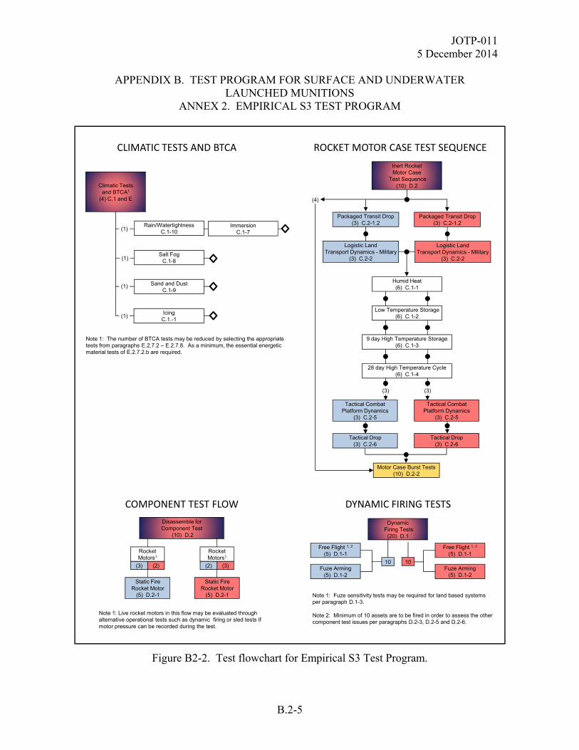
JOTP-011 5 December 2014
APPENDIX B. TEST PROGRAM FOR SURFACE AND UNDERWATER LAUNCHED MUNITIONS
ANNEX 2. EMPIRICAL S3 TEST PROGRAM
B.2-5
Figure B2-2. Test flowchart for Empirical S3 Test Program.
CLIMATIC TESTS AND BTCA
Sand and DustC.1-9
Rain/WatertightnessC.1-10
Salt FogC.1-8
ImmersionC.1-7
Climatic Tests and BTCA1
(4) C.1 and E
(1)
(1)
(1)
(1)Icing
C.1.-1
Note 1: The number of BTCA tests may be reduced by selecting the appropriate tests from paragraphs E.2.7.2 – E.2.7.8. As a minimum, the essential energetic material tests of E.2.7.2.b are required.
DYNAMIC FIRING TESTS
Free Flight 1, 2
(5) D.1-1
10Fuze Arming
(5) D.1-2
10
Free Flight 1, 2
(5) D.1-1
Fuze Arming(5) D.1-2
DynamicFiring Tests (20) D.1
Note 1: Fuze sensitivity tests may be required for land based systems per paragraph D.1-3.
Note 2: Minimum of 10 assets are to be fired in order to assess the other component test issues per paragraphs D.2-3, D.2-5 and D.2-6.
COMPONENT TEST FLOW
Disassemble for Component Test
(10) D.2
Static Fire Rocket Motor
(5) D.2-1
Static Fire Rocket Motor
(5) D.2-1
Rocket Motors1
(3)(2)
Rocket Motors1
(2)(3)
Note 1: Live rocket motors in this flow may be evaluated through alternative operational tests such as dynamic firing or sled tests if motor pressure can be recorded during the test.
Motor Case Burst Tests(10) D.2-2
9 day High Temperature Storage (6) C.1-3
28 day High Temperature Cycle (6) C.1-4
Low Temperature Storage (6) C.1-2
Packaged Transit Drop (3) C.2-1.2
Logistic Land Transport Dynamics - Military
(3) C.2-2
Tactical Combat Platform Dynamics
(3) C.2-5
Tactical Combat Platform Dynamics
(3) C.2-5
(3)(3)
Humid Heat (6) C.1-1
(4)
Inert Rocket Motor Case
Test Sequence(10) D.2
Packaged Transit Drop (3) C.2-1.2
Logistic Land Transport Dynamics - Military
(3) C.2-2
Tactical Drop(3) C.2-6
Tactical Drop(3) C.2-6
ROCKET MOTOR CASE TEST SEQUENCE
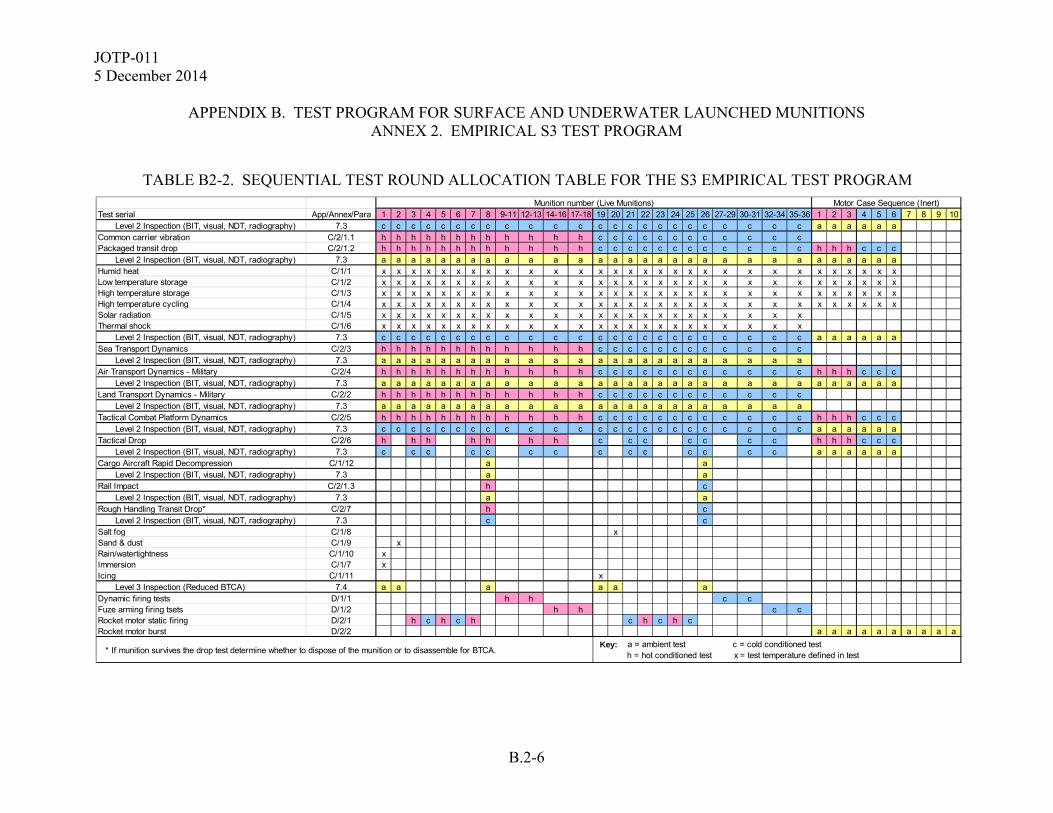
JOTP-011 5 December 2014
APPENDIX B. TEST PROGRAM FOR SURFACE AND UNDERWATER LAUNCHED MUNITIONS
ANNEX 2. EMPIRICAL S3 TEST PROGRAM
B.2-6
TABLE B2-2. SEQUENTIAL TEST ROUND ALLOCATION TABLE FOR THE S3 EMPIRICAL TEST PROGRAM
Test serial App/Annex/Para 1 2 3 4 5 6 7 8 9-11 12-13 14-16 17-18 19 20 21 22 23 24 25 26 27-29 30-31 32-34 35-36 1 2 3 4 5 6 7 8 9 10 Level 2 Inspection (BIT, visual, NDT, radiography) 7.3 c c c c c c c c c c c c c c c c c c c c c c c c a a a a a aCommon carrier vibration C/2/1.1 h h h h h h h h h h h h c c c c c c c c c c c cPackaged transit drop C/2/1.2 h h h h h h h h h h h h c c c c c c c c c c c c h h h c c c Level 2 Inspection (BIT, visual, NDT, radiography) 7.3 a a a a a a a a a a a a a a a a a a a a a a a a a a a a a aHumid heat C/1/1 x x x x x x x x x x x x x x x x x x x x x x x x x x x x x xLow temperature storage C/1/2 x x x x x x x x x x x x x x x x x x x x x x x x x x x x x xHigh temperature storage C/1/3 x x x x x x x x x x x x x x x x x x x x x x x x x x x x x xHigh temperature cycling C/1/4 x x x x x x x x x x x x x x x x x x x x x x x x x x x x x xSolar radiation C/1/5 x x x x x x x x x x x x x x x x x x x x x x x xThermal shock C/1/6 x x x x x x x x x x x x x x x x x x x x x x x x Level 2 Inspection (BIT, visual, NDT, radiography) 7.3 c c c c c c c c c c c c c c c c c c c c c c c c a a a a a aSea Transport Dynamics C/2/3 h h h h h h h h h h h h c c c c c c c c c c c c Level 2 Inspection (BIT, visual, NDT, radiography) 7.3 a a a a a a a a a a a a a a a a a a a a a a a aAir Transport Dynamics - Military C/2/4 h h h h h h h h h h h h c c c c c c c c c c c c h h h c c c Level 2 Inspection (BIT, visual, NDT, radiography) 7.3 a a a a a a a a a a a a a a a a a a a a a a a a a a a a a aLand Transport Dynamics - Military C/2/2 h h h h h h h h h h h h c c c c c c c c c c c c Level 2 Inspection (BIT, visual, NDT, radiography) 7.3 a a a a a a a a a a a a a a a a a a a a a a a aTactical Combat Platform Dynamics C/2/5 h h h h h h h h h h h h c c c c c c c c c c c c h h h c c c Level 2 Inspection (BIT, visual, NDT, radiography) 7.3 c c c c c c c c c c c c c c c c c c c c c c c c a a a a a aTactical Drop C/2/6 h h h h h h h c c c c c c c h h h c c c Level 2 Inspection (BIT, visual, NDT, radiography) 7.3 c c c c c c c c c c c c c c a a a a a aCargo Aircraft Rapid Decompression C/1/12 a a Level 2 Inspection (BIT, visual, NDT, radiography) 7.3 a aRail Impact C/2/1.3 h c Level 2 Inspection (BIT, visual, NDT, radiography) 7.3 a aRough Handling Transit Drop* C/2/7 h c Level 2 Inspection (BIT, visual, NDT, radiography) 7.3 c cSalt fog C/1/8 xSand & dust C/1/9 xRain/watertightness C/1/10 xImmersion C/1/7 xIcing C/1/11 x Level 3 Inspection (Reduced BTCA) 7.4 a a a a a aDynamic firing tests D/1/1 h h c cFuze arming firing tsets D/1/2 h h c cRocket motor static firing D/2/1 h c h c h c h c h cRocket motor burst D/2/2 a a a a a a a a a a
* If munition survives the drop test determine whether to dispose of the munition or to disassemble for BTCA.
Munition number (Live Munitions) Motor Case Sequence (Inert)
Key: a = ambient test c = cold conditioned test h = hot conditioned test x = test temperature defined in test

JOTP-011 5 December 2014
APPENDIX B. TEST PROGRAM FOR SURFACE AND UNDERWATER LAUNCHED MUNITIONS
ANNEX 3. WORKED EXAMPLE OF TEST TAILORING FOR A SURFACE LAUNCHED MISSILE SYSTEM
B.3-1
B.3-1 INTRODUCTION. The text below gives a worked example showing how the test quantities from an Empirical S3 Test Program can be tailored given a specific set of circumstances. It is not to be used as the definitive test quantities set or as a substitute for those quantities provided in Appendix B, Annex 2. A similar approach can be used for the Analytical S3 Test Program. As stated in paragraph 6.3, deviations from the S3 assessment testing program shall be approved by National S3 Authority(ies) or other appropriate Authorities prior to the start of testing. B.3-2 TEST QUANTITIES TAILORING – WORKED EXAMPLE. B.3-2.1 Example System Description. For the purposes of this example, an S3 test program is to be conducted for a previously fielded system with a new propulsion unit. The modifications include new propellant charge weight and new igniter, but structural and sealing components remain unchanged. Substantial igniter development data has been provided. Warhead, guidance, and seeker systems are unchanged, as is the anticipated user environment. The warhead safe and arming/fuze component(s) have been qualified (or has a favourable S3 assessment) in accordance with MIL-STD-331. B.3-2.2 Tailoring of Test Asset Configuration. Non-tactical components. The test assets may include inert warhead and other non-tactical components if those components have previously completed S3 testing with the exception that fully functional guidance and control systems will be required for the firing safety test assets. Any non-tactical mass simulants are required to have thermal, structural, and dynamic characteristics similar to the tactical hardware. B.3-2.3 Sequential Environmental Trial and Operation Test Tailoring Considerations. B.3-2.3.1 Reduction in Climatic Test Requirements. Immersion, Salt Fog, Sand and Dust, Rain/Watertightness, Icing, and Altitude tests may be eliminated since no changes to the weapon seals have been made. B.3-2.3.2 Reduction in BTCA Test Requirements. BTCA is an underpinning principle of S3 testing and analysis since this provides significant information in respect to residual safety margins. Furthermore, BTCA data obtained as part of a S3 program can also form the body of evidence to be used during subsequent In-Service Surveillance activities. Additionally, some Nations place greater emphasis on the results of BTCA

JOTP-011 5 December 2014
APPENDIX B. TEST PROGRAM FOR SURFACE AND UNDERWATER
LAUNCHED MUNITIONS ANNEX 3. WORKED EXAMPLE OF TEST TAILORING FOR A SURFACE LAUNCHED
MISSILE SYSTEM
B.3-2
than other tests. For these reasons this cannot be eliminated from any S3 program. Four assets is the minimum for this example in order to provide adequate material for the required AOP-7 testing. Furthermore, BTCA is only required for the new components (rocket motor and igniter). B.3-2.3.3 Reduction in Firing Safety Test Requirements. Firing safety tests should not be eliminated, but the quantities may be reduced based on confidence from prior field experience, developmental tests, and static firing data. Minimum quantities for this example are five hot and five cold for Dynamic Firing. The Fuze system firings may be eliminated since the fuze is unchanged. B.3-2.3.4 Elimination of Rocket Motor Case Test Requirements. These tests may be eliminated since no material change to the pressure vessel or structural components of the propulsion unit and prior S3 showed no material degradation and substantial safety margin. Burst integrity will be further assessed based on Static Firing data. B.3-2.3.5 Use Of Development Test Data. Substantial development data has been provided and reviewed; and the assessment of the design has been found to support the reduction of test quantities. B.3-2.4 Non-Sequential Test Tailoring Considerations. B.3-2.4.1 Reduction in 12-Meter Logistic Safety Drop Test Asset Quantity. Since the full system has been previously qualified, only one missile with live propulsion unit (non-tactical warhead, guidance and seeker) is required. This drop needs to be in the worst case orientation for the propulsion unit. B.3-2.4.2 Elimination of Fluid Contamination and Mould Growth Test Requirements. These tests may be eliminated since no changes to the structural components or weapon seals have been made. B.3-3 TAILORED TEST PROGRAM. Based on the preceding discussion, the following test assets may be reduced from the Empirical S3 Test Flow: a. 10 ea Rocket Motor Burst Integrity and Other Pressure Vessel Burst Integrity

JOTP-011 5 December 2014
APPENDIX B. TEST PROGRAM FOR SURFACE AND UNDERWATER LAUNCHED MUNITIONS
ANNEX 3. WORKED EXAMPLE OF TEST TAILORING FOR A SURFACE LAUNCHED MISSILE SYSTEM
B.3-3
b. 6 ea Dynamic Firing Tests This effectively removes 20 munitions (10 live and 10 inert rocket motors) from the 46 munition sequential test program as shown in Table B3-1 leaving just 26 weapons as shown in Table B3-2. Additionally, the number of weapons required for Logistic Drop Testing is reduced from three to one and further reductions may be achieved for Insensitive Muntions, Hazard Classification, and E3 tests.

JOTP-011 5 December 2014
APPENDIX B. TEST PROGRAM FOR SURFACE AND UNDERWATER LAUNCHED MUNITIONS
ANNEX 3. WORKED EXAMPLE OF TEST TAILORING FOR A SURFACE LAUNCHED MISSILE SYSTEM
B.3-4
TABLE B3-1. EXAMPLE TAILORED SEQUENTIAL TEST ROUND ALLOCATION TABLE FOR THE S3 EMPIRICAL TEST PROGRAM
Test serial App/Annex/Para 1 2 3 4 5 6 7 8 9-11 12-13 14-16 17-18 19 20 21 22 23 24 25 26 27-29 30-31 32-34 35-36 1 2 3 4 5 6 7 8 9 10 Level 2 Inspection (BIT, visual, NDT, radiography) 7.3 c c c c c c c c c c c c c c c c c c c c c c c c a a a a a aCommon carrier vibration C/2/1.1 h h h h h h h h h h h h c c c c c c c c c c c cPackaged transit drop C/2/1.2 h h h h h h h h h h h h c c c c c c c c c c c c h h h c c c Level 2 Inspection (BIT, visual, NDT, radiography) 7.3 a a a a a a a a a a a a a a a a a a a a a a a a a a a a a aHumid heat C/1/1 x x x x x x x x x x x x x x x x x x x x x x x x x x x x x xLow temperature storage C/1/2 x x x x x x x x x x x x x x x x x x x x x x x x x x x x x xHigh temperature storage C/1/3 x x x x x x x x x x x x x x x x x x x x x x x x x x x x x xHigh temperature cycling C/1/4 x x x x x x x x x x x x x x x x x x x x x x x x x x x x x xSolar radiation C/1/5 x x x x x x x x x x x x x x x x x x x x x x x xThermal shock C/1/6 x x x x x x x x x x x x x x x x x x x x x x x x Level 2 Inspection (BIT, visual, NDT, radiography) 7.3 c c c c c c c c c c c c c c c c c c c c c c c c a a a a a aSea Transport Dynamics C/2/3 h h h h h h h h h h h h c c c c c c c c c c c c Level 2 Inspection (BIT, visual, NDT, radiography) 7.3 a a a a a a a a a a a a a a a a a a a a a a a a a a a a a aAir Transport Dynamics - Military C/2/4 h h h h h h h h h h h h c c c c c c c c c c c c h h h c c c Level 2 Inspection (BIT, visual, NDT, radiography) 7.3 a a a a a a a a a a a a a a a a a a a a a a a aLand Transport Dynamics - Military C/2/2 h h h h h h h h h h h h c c c c c c c c c c c c Level 2 Inspection (BIT, visual, NDT, radiography) 7.3 a a a a a a a a a a a a a a a a a a a a a a a a a a a a a aTactical Combat Platform Dynamics C/2/5 h h h h h h h h h h h h c c c c c c c c c c c c h h h c c c Level 2 Inspection (BIT, visual, NDT, radiography) 7.3 c c c c c c c c c c c c c c c c c c c c c c c c a a a a a aTactical Drop C/2/6 h h h h h h h c c c c c c c h h h c c c Level 2 Inspection (BIT, visual, NDT, radiography) 7.3 c c c c c c c c c c c c c c a a a a a aCargo Aircraft Rapid Decompression C/1/12 a a Level 2 Inspection (BIT, visual, NDT, radiography) 7.3 a aRail Impact C/2/1.3 h c Level 2 Inspection (BIT, visual, NDT, radiography) 7.3 a aRough Handling Transit Drop* C/2/7 h c Level 2 Inspection (BIT, visual, NDT, radiography) 7.3 c cSalt fog C/1/8 xSand & dust C/1/9 xRain/watertightness C/1/10 xImmersion C/1/7 xIcing C/1/11 x Level 3 Inspection (Reduced BTCA) 7.4 a a a a a aDynamic firing tests D/1/1 h h c cFuze arming firing tsets D/1/2 h h c cRocket motor static firing D/2/1 h c h c h c h c h cRocket motor burst D/2/2 a a a a a a a a a a
* If munition survives the drop test determine whether to dispose of the munition or to disassemble for BTCA. Key: a = ambient test c = cold conditioned test = eliminated by tailoring
h = hot conditioned test x = test temperature defined in test
Munition number (Live Munitions) Motor Case Sequence (Inert)

JOTP-011 5 December 2014
APPENDIX B. TEST PROGRAM FOR SURFACE AND UNDERWATER LAUNCHED MUNITIONS ANNEX 3. WORKED EXAMPLE OF TEST TAILORING FOR A SURFACE LAUNCHED MISSILE SYSTEM
B.3-5
TABLE B3-2. EXAMPLE TAILORED SEQUENTIAL ROUND ALLOCATION FOR EMPIRICAL S3 TEST PROGRAM
Test serial App/Annex/Para 1 2 3 4 5 6 7 8 9-11 12-13 14 15 16 17 18 19 20 21 22-24 25-26 Level 2 Inspection (BIT, visual, NDT, radiography) 7.3 c c c c c c c c c c c c c c c c c c c cCommon carrier vibration C/2/1.1 h h h h h h h h h h c c c c c c c c c cPackaged transit drop C/2/1.2 h h h h h h h h h h c c c c c c c c c c Level 2 Inspection (BIT, visual, NDT, radiography) 7.3 a a a a a a a a a a a a a a a a a a a aHumid heat C/1/1 x x x x x x x x x x x x x x x x x x x xLow temperature storage C/1/2 x x x x x x x x x x x x x x x x x x x xHigh temperature storage C/1/3 x x x x x x x x x x x x x x x x x x x xHigh temperature cycling C/1/4 x x x x x x x x x x x x x x x x x x x xSolar radiation C/1/5 x x x x x x x x x x x x x x x x x x x xThermal shock C/1/6 x x x x x x x x x x x x x x x x x x x x Level 2 Inspection (BIT, visual, NDT, radiography) 7.3 c c c c c c c c c c c c c c c c c c c cSea Transport Dynamics C/2/3 h h h h h h h h h h c c c c c c c c c c Level 2 Inspection (BIT, visual, NDT, radiography) 7.3 a a a a a a a a a a a a a a a a a a a aAir Transport Dynamics - Military C/2/4 h h h h h h h h h h c c c c c c c c c c Level 2 Inspection (BIT, visual, NDT, radiography) 7.3 a a a a a a a a a a a a a a a a a a a aLand Transport Dynamics - Military C/2/2 h h h h h h h h h h c c c c c c c c c c Level 2 Inspection (BIT, visual, NDT, radiography) 7.3 a a a a a a a a a a a a a a a a a a a aTactical Combat Platform Dynamics C/2/5 h h h h h h h h h h c c c c c c c c c c Level 2 Inspection (BIT, visual, NDT, radiography) 7.3 c c c c c c c c c c c c c c c c c c c cTactical Drop C/2/6 h h h h h h c c c c c c Level 2 Inspection (BIT, visual, NDT, radiography) 7.3 c c c c c c c c c c c cCargo Aircraft Rapid Decompression C/1/12 a a Level 2 Inspection (BIT, visual, NDT, radiography) 7.3 a aRail Impact C/2/1.3 h c Level 2 Inspection (BIT, visual, NDT, radiography) 7.3 a aRough Handling Transit Drop* C/2/7 h c Level 2 Inspection (BIT, visual, NDT, radiography) 7.3 c c Level 3 Inspection (Reduced BTCA) 7.4 a a a a a aDynamic firing tests D/1/1 h h c c
* If munition survives the drop test determine whether to dispose of the munition or to disassemble for BTCA.
Munition number (Live Munitions)
Key: a = ambient test c = cold conditioned test h = hot conditioned test x = test temperature defined in test

JOTP-011 5 December 2014
APPENDIX B. TEST PROGRAM FOR SURFACE AND UNDERWATER
LAUNCHED MUNITIONS ANNEX 3. WORKED EXAMPLE OF TEST TAILORING FOR A SURFACE LAUNCHED
MISSILE SYSTEM
B.3-6
(This page is intentionally blank.)

JOTP-011 5 December 2014
APPENDIX C. ENVIRONMENTAL TEST DESCRIPTIONS
C-1
This document was developed within the international community and is written with references to both US and NATO test procedures to provide a framework for international procurement and test programs. Table I2-1 (Appendix I, Annex 2) provides cross reference of similar national and international test standards. This Appendix provides descriptions of all of the environmental (climatic and dynamic) tests required in the S3 Test Programs included in Appendix B. Annex 1 contains the climatic test descriptions; Annex 2 contains the dynamic test descriptions. Rationales for all environmental tests are provided in Appendix A.

JOTP-011 5 December 2014
APPENDIX C. ENVIRONMENTAL TEST DESCRIPTIONS
C-2
(This page is intentionally blank.)
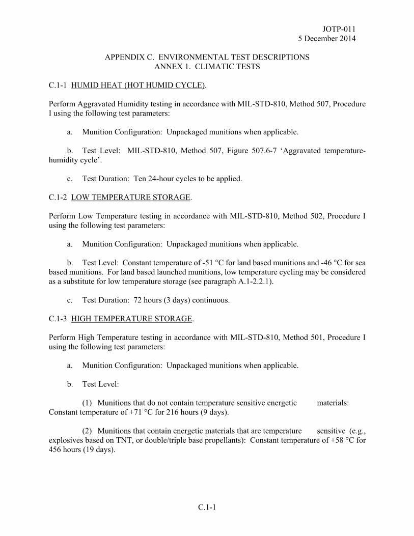
JOTP-011 5 December 2014
APPENDIX C. ENVIRONMENTAL TEST DESCRIPTIONS
ANNEX 1. CLIMATIC TESTS
C.1-1
C.1-1 HUMID HEAT (HOT HUMID CYCLE). Perform Aggravated Humidity testing in accordance with MIL-STD-810, Method 507, Procedure I using the following test parameters: a. Munition Configuration: Unpackaged munitions when applicable. b. Test Level: MIL-STD-810, Method 507, Figure 507.6-7 ‘Aggravated temperature-humidity cycle’. c. Test Duration: Ten 24-hour cycles to be applied. C.1-2 LOW TEMPERATURE STORAGE. Perform Low Temperature testing in accordance with MIL-STD-810, Method 502, Procedure I using the following test parameters: a. Munition Configuration: Unpackaged munitions when applicable. b. Test Level: Constant temperature of -51 °C for land based munitions and -46 °C for sea based munitions. For land based launched munitions, low temperature cycling may be considered as a substitute for low temperature storage (see paragraph A.1-2.2.1). c. Test Duration: 72 hours (3 days) continuous. C.1-3 HIGH TEMPERATURE STORAGE. Perform High Temperature testing in accordance with MIL-STD-810, Method 501, Procedure I using the following test parameters: a. Munition Configuration: Unpackaged munitions when applicable. b. Test Level: (1) Munitions that do not contain temperature sensitive energetic materials: Constant temperature of +71 °C for 216 hours (9 days). (2) Munitions that contain energetic materials that are temperature sensitive (e.g., explosives based on TNT, or double/triple base propellants): Constant temperature of +58 °C for 456 hours (19 days).
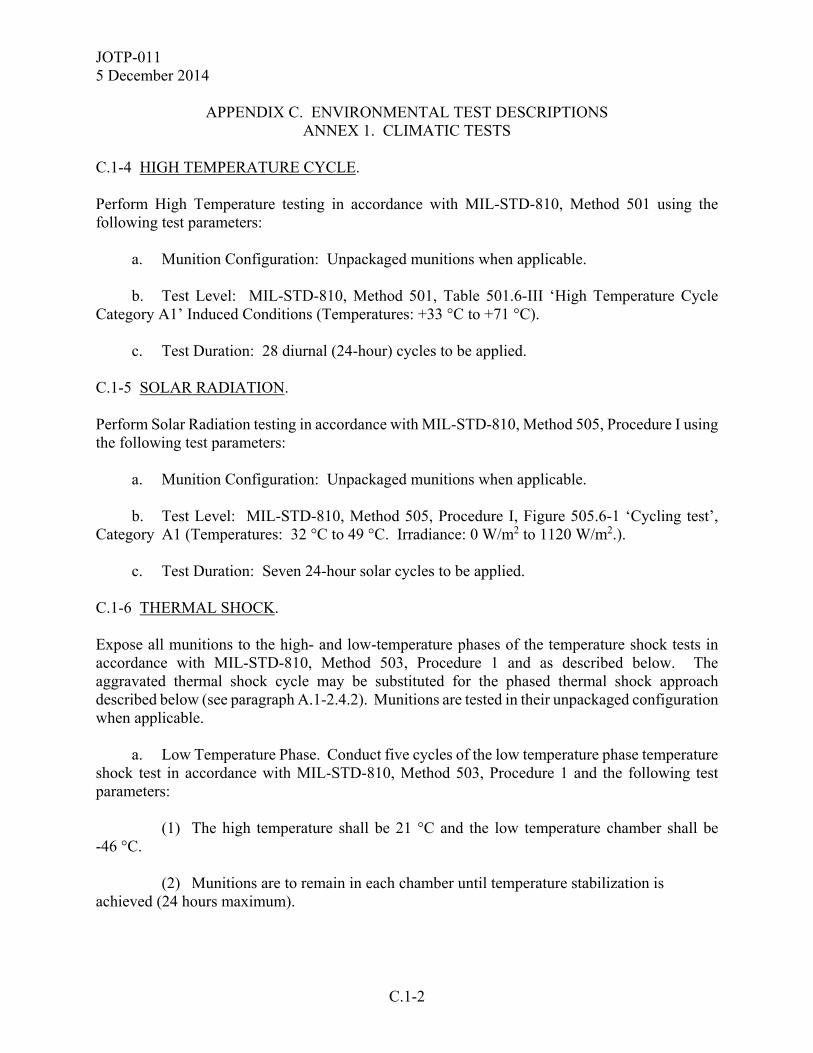
JOTP-011 5 December 2014
APPENDIX C. ENVIRONMENTAL TEST DESCRIPTIONS
ANNEX 1. CLIMATIC TESTS
C.1-2
C.1-4 HIGH TEMPERATURE CYCLE. Perform High Temperature testing in accordance with MIL-STD-810, Method 501 using the following test parameters: a. Munition Configuration: Unpackaged munitions when applicable. b. Test Level: MIL-STD-810, Method 501, Table 501.6-III ‘High Temperature Cycle Category A1’ Induced Conditions (Temperatures: +33 °C to +71 °C). c. Test Duration: 28 diurnal (24-hour) cycles to be applied. C.1-5 SOLAR RADIATION. Perform Solar Radiation testing in accordance with MIL-STD-810, Method 505, Procedure I using the following test parameters: a. Munition Configuration: Unpackaged munitions when applicable. b. Test Level: MIL-STD-810, Method 505, Procedure I, Figure 505.6-1 ‘Cycling test’, Category A1 (Temperatures: 32 °C to 49 °C. Irradiance: 0 W/m2 to 1120 W/m2.). c. Test Duration: Seven 24-hour solar cycles to be applied. C.1-6 THERMAL SHOCK. Expose all munitions to the high- and low-temperature phases of the temperature shock tests in accordance with MIL-STD-810, Method 503, Procedure 1 and as described below. The aggravated thermal shock cycle may be substituted for the phased thermal shock approach described below (see paragraph A.1-2.4.2). Munitions are tested in their unpackaged configuration when applicable. a. Low Temperature Phase. Conduct five cycles of the low temperature phase temperature shock test in accordance with MIL-STD-810, Method 503, Procedure 1 and the following test parameters: (1) The high temperature shall be 21 °C and the low temperature chamber shall be -46 °C. (2) Munitions are to remain in each chamber until temperature stabilization is achieved (24 hours maximum).

JOTP-011 5 December 2014
APPENDIX C. ENVIRONMENTAL TEST DESCRIPTIONS
ANNEX 1. CLIMATIC TESTS
C.1-3
b. High Temperature Phase. Conduct five cycles of the high temperature phase temperature shock test in accordance with MIL-STD-810, Method 503, Procedure 1 and the following test parameters: (1) The high-temperature shall be the unpackaged SRE temperature and the low-temperature chamber shall be -5 °C. (2) Munitions are to remain in each chamber until temperature stabilization is achieved (24 hours maximum). C.1-7 IMMERSION/PRESSURIZATION. a. Immersion. Perform per MIL-STD-810, Method 512, Procedure 1 on the munition in the unpackaged configuration with the following test parameters: (1) Conditioning temperature. Surface launched munitions are to be preconditioned to a temperature of 27 °C above the water temperature to represent exposure to solar heating immediately prior to immersion. Underwater launched munitions will be tested at standard ambient conditions. (2) Depth of immersion. Apply an immersion depth of one meter, or equivalent pressure for surface launched munitions, to represent complete immersion. (3) Duration of immersion. Munitions are to remain immersed for a period of 30-minutes. b. Pressurization. Perform a hydrostatic pressure test per MIL-STD-810, Method 512, Procedure 1 on an underwater launched, structurally similar inert munition with the following parameters: (1) The munition shall be maintained in a pre-launch or launch configuration, i.e., completely immersed in water. (2) The applied external pressure shall be 110% of baseline launch pressure observed during a launch event, excluding overpressure. (3) The munition will be pressurized with a quasi-static increase of external pressure [i.e., 689 KPa/min (100 psi/min)]. (4) Duration of pressure test. Munitions are to remain pressured for a period of 30 minutes.

JOTP-011 5 December 2014
APPENDIX C. ENVIRONMENTAL TEST DESCRIPTIONS
ANNEX 1. CLIMATIC TESTS
C.1-4
C.1-8 SALT FOG. Perform per MIL-STD-810, Method 509 on the munition in the unpackaged configuration when applicable for two cycles alternating wet-dry-wet-dry (24 hrs each). a. Munition Configuration: Unpackaged munitions when applicable. b. Test Levels: Use default parameters as specified in MIL-STD-810, Method 509. c. Test Duration: Two alternating 48 hour wet-dry cycles (48 hrs/cycle). C.1-9 SAND AND DUST. Perform Sand and Dust testing in accordance with MIL-STD-810, Method 510 Procedures I (Blowing Dust) and II (Blowing Sand) using the following test parameters: a. Munition Configuration: Unpackaged munitions when applicable. b. Conditioning Temperature: Munitions are to be preconditioned to a temperature of +49 °C prior to exposure. c. Test Levels: (1) Wind Blown Dust - Use default parameters as specified in MIL-STD-810, Method 510, Procedure I. (2) Wind Blown Sand - Use default parameters as specified in MIL-STD-810, Method 510, Procedure II for material that may be used near operating surface vehicles (sand concentration = 1.1±0.3 g/m3; wind velocity = 18 to 30 m/s). (3) There is no requirement to test underwater launched munitions. d. Test Duration: Apply default parameters as specified in MIL-STD-810, Method 510. Note that it is recommended to conduct the sand and dust tests individually. C.1-10 RAIN/WATERTIGHTNESS. Perform Rain/Watertightness testing in accordance with MIL-STD-810, Method 506, Procedure I using the following test parameters: a. Munition Configuration: Unpackaged munitions when applicable.
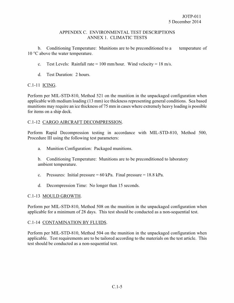
JOTP-011 5 December 2014
APPENDIX C. ENVIRONMENTAL TEST DESCRIPTIONS
ANNEX 1. CLIMATIC TESTS
C.1-5
b. Conditioning Temperature: Munitions are to be preconditioned to a temperature of 10 °C above the water temperature. c. Test Levels: Rainfall rate = 100 mm/hour. Wind velocity = 18 m/s. d. Test Duration: 2 hours. C.1-11 ICING. Perform per MIL-STD-810, Method 521 on the munition in the unpackaged configuration when applicable with medium loading (13 mm) ice thickness representing general conditions. Sea based munitions may require an ice thickness of 75 mm in cases where extremely heavy loading is possible for items on a ship deck. C.1-12 CARGO AIRCRAFT DECOMPRESSION. Perform Rapid Decompression testing in accordance with MIL-STD-810, Method 500, Procedure III using the following test parameters: a. Munition Configuration: Packaged munitions. b. Conditioning Temperature: Munitions are to be preconditioned to laboratory ambient temperature. c. Pressures: Initial pressure = 60 kPa. Final pressure = 18.8 kPa. d. Decompression Time: No longer than 15 seconds. C.1-13 MOULD GROWTH. Perform per MIL-STD-810, Method 508 on the munition in the unpackaged configuration when applicable for a minimum of 28 days. This test should be conducted as a non-sequential test. C.1-14 CONTAMINATION BY FLUIDS. Perform per MIL-STD-810, Method 504 on the munition in the unpackaged configuration when applicable. Test requirements are to be tailored according to the materials on the test article. This test should be conducted as a non-sequential test.

JOTP-011 5 December 2014
APPENDIX C. ENVIRONMENTAL TEST DESCRIPTIONS
ANNEX 1. CLIMATIC TESTS
C.1-6
(This page is intentionally blank.)
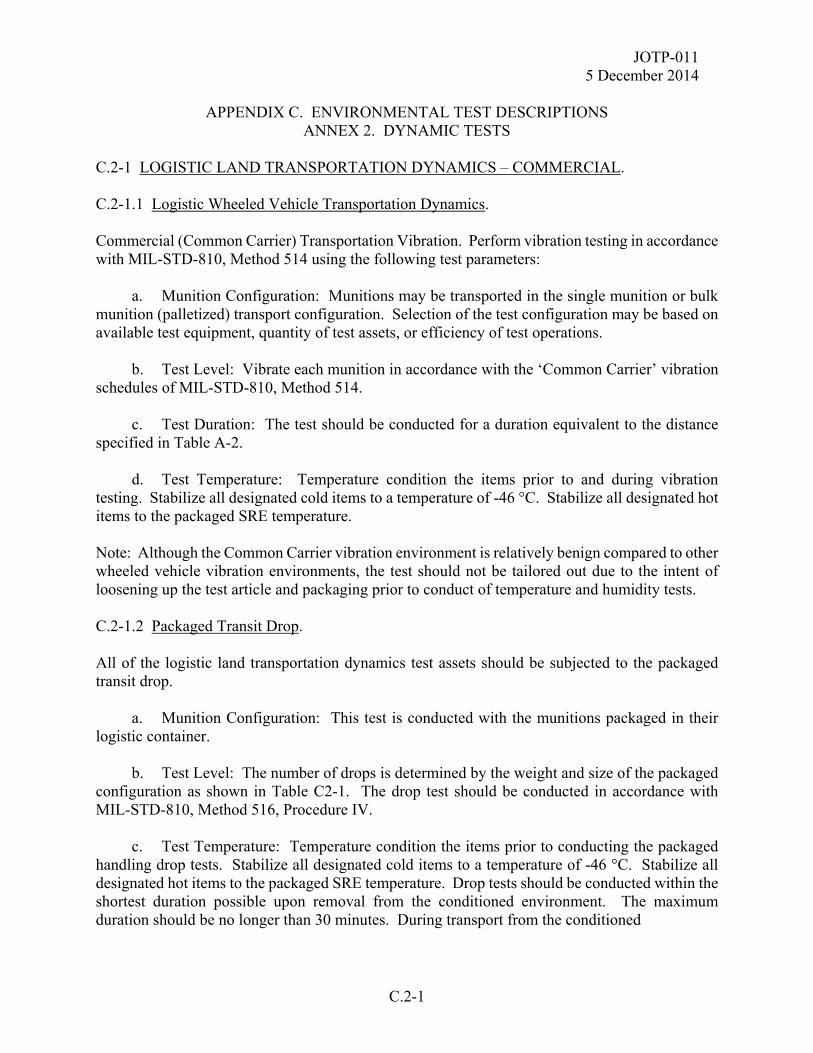
JOTP-011 5 December 2014
APPENDIX C. ENVIRONMENTAL TEST DESCRIPTIONS
ANNEX 2. DYNAMIC TESTS
C.2-1
C.2-1 LOGISTIC LAND TRANSPORTATION DYNAMICS – COMMERCIAL. C.2-1.1 Logistic Wheeled Vehicle Transportation Dynamics. Commercial (Common Carrier) Transportation Vibration. Perform vibration testing in accordance with MIL-STD-810, Method 514 using the following test parameters: a. Munition Configuration: Munitions may be transported in the single munition or bulk munition (palletized) transport configuration. Selection of the test configuration may be based on available test equipment, quantity of test assets, or efficiency of test operations. b. Test Level: Vibrate each munition in accordance with the ‘Common Carrier’ vibration schedules of MIL-STD-810, Method 514. c. Test Duration: The test should be conducted for a duration equivalent to the distance specified in Table A-2. d. Test Temperature: Temperature condition the items prior to and during vibration testing. Stabilize all designated cold items to a temperature of -46 °C. Stabilize all designated hot items to the packaged SRE temperature. Note: Although the Common Carrier vibration environment is relatively benign compared to other wheeled vehicle vibration environments, the test should not be tailored out due to the intent of loosening up the test article and packaging prior to conduct of temperature and humidity tests. C.2-1.2 Packaged Transit Drop. All of the logistic land transportation dynamics test assets should be subjected to the packaged transit drop. a. Munition Configuration: This test is conducted with the munitions packaged in their logistic container. b. Test Level: The number of drops is determined by the weight and size of the packaged configuration as shown in Table C2-1. The drop test should be conducted in accordance with MIL-STD-810, Method 516, Procedure IV. c. Test Temperature: Temperature condition the items prior to conducting the packaged handling drop tests. Stabilize all designated cold items to a temperature of -46 °C. Stabilize all designated hot items to the packaged SRE temperature. Drop tests should be conducted within the shortest duration possible upon removal from the conditioned environment. The maximum duration should be no longer than 30 minutes. During transport from the conditioned
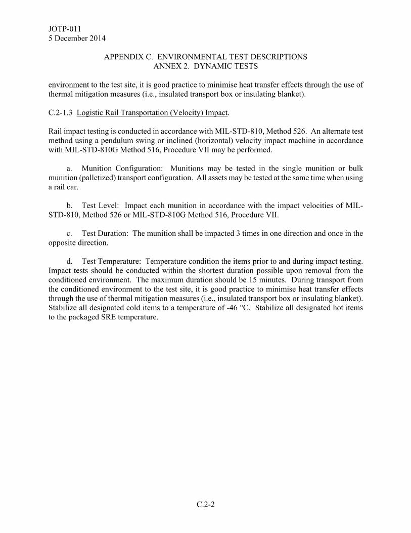
JOTP-011 5 December 2014
APPENDIX C. ENVIRONMENTAL TEST DESCRIPTIONS
ANNEX 2. DYNAMIC TESTS
C.2-2
environment to the test site, it is good practice to minimise heat transfer effects through the use of thermal mitigation measures (i.e., insulated transport box or insulating blanket). C.2-1.3 Logistic Rail Transportation (Velocity) Impact. Rail impact testing is conducted in accordance with MIL-STD-810, Method 526. An alternate test method using a pendulum swing or inclined (horizontal) velocity impact machine in accordance with MIL-STD-810G Method 516, Procedure VII may be performed. a. Munition Configuration: Munitions may be tested in the single munition or bulk munition (palletized) transport configuration. All assets may be tested at the same time when using a rail car. b. Test Level: Impact each munition in accordance with the impact velocities of MIL-STD-810, Method 526 or MIL-STD-810G Method 516, Procedure VII. c. Test Duration: The munition shall be impacted 3 times in one direction and once in the opposite direction. d. Test Temperature: Temperature condition the items prior to and during impact testing. Impact tests should be conducted within the shortest duration possible upon removal from the conditioned environment. The maximum duration should be 15 minutes. During transport from the conditioned environment to the test site, it is good practice to minimise heat transfer effects through the use of thermal mitigation measures (i.e., insulated transport box or insulating blanket). Stabilize all designated cold items to a temperature of -46 °C. Stabilize all designated hot items to the packaged SRE temperature.
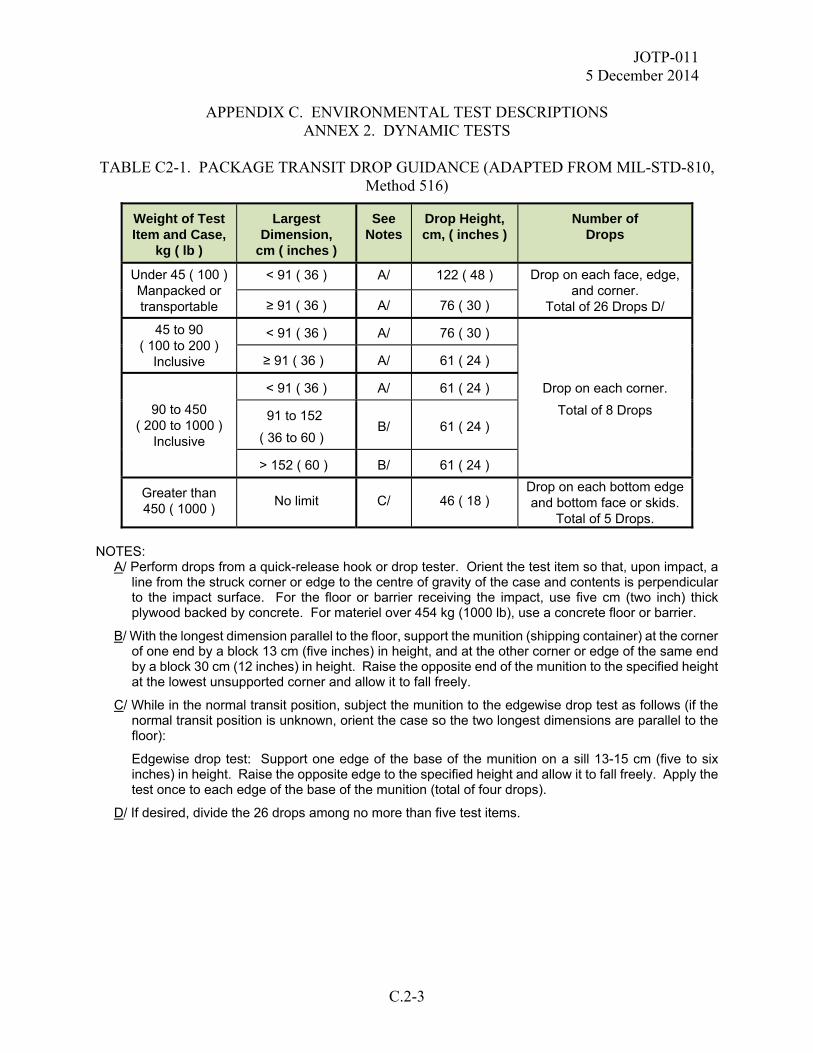
JOTP-011 5 December 2014
APPENDIX C. ENVIRONMENTAL TEST DESCRIPTIONS
ANNEX 2. DYNAMIC TESTS
C.2-3
TABLE C2-1. PACKAGE TRANSIT DROP GUIDANCE (ADAPTED FROM MIL-STD-810, Method 516)
Weight of Test Item and Case,
kg ( lb )
Largest Dimension,
cm ( inches )
See Notes
Drop Height, cm, ( inches )
Number of Drops
Under 45 ( 100 ) Manpacked or transportable
< 91 ( 36 ) A/ 122 ( 48 ) Drop on each face, edge, and corner.
Total of 26 Drops D/ ≥ 91 ( 36 ) A/ 76 ( 30 )
45 to 90 ( 100 to 200 )
Inclusive
< 91 ( 36 ) A/ 76 ( 30 )
Drop on each corner.
Total of 8 Drops
≥ 91 ( 36 ) A/ 61 ( 24 )
90 to 450 ( 200 to 1000 )
Inclusive
< 91 ( 36 ) A/ 61 ( 24 )
91 to 152
( 36 to 60 ) B/ 61 ( 24 )
> 152 ( 60 ) B/ 61 ( 24 )
Greater than 450 ( 1000 )
No limit C/ 46 ( 18 ) Drop on each bottom edge and bottom face or skids.
Total of 5 Drops. NOTES:
A/ Perform drops from a quick-release hook or drop tester. Orient the test item so that, upon impact, a line from the struck corner or edge to the centre of gravity of the case and contents is perpendicular to the impact surface. For the floor or barrier receiving the impact, use five cm (two inch) thick plywood backed by concrete. For materiel over 454 kg (1000 lb), use a concrete floor or barrier.
B/ With the longest dimension parallel to the floor, support the munition (shipping container) at the corner of one end by a block 13 cm (five inches) in height, and at the other corner or edge of the same end by a block 30 cm (12 inches) in height. Raise the opposite end of the munition to the specified height at the lowest unsupported corner and allow it to fall freely.
C/ While in the normal transit position, subject the munition to the edgewise drop test as follows (if the normal transit position is unknown, orient the case so the two longest dimensions are parallel to the floor):
Edgewise drop test: Support one edge of the base of the munition on a sill 13-15 cm (five to six inches) in height. Raise the opposite edge to the specified height and allow it to fall freely. Apply the test once to each edge of the base of the munition (total of four drops).
D/ If desired, divide the 26 drops among no more than five test items.
JOTP-011 5 December 2014
APPENDIX C. ENVIRONMENTAL TEST DESCRIPTIONS
ANNEX 2. DYNAMIC TESTS
C.2-4
C.2-2 LOGISTIC LAND TRANSPORTATION DYNAMICS – MILITARY. For surface and underwater launched munitions, military land transportation dynamics addresses the mechanical environments that may be encountered during military transportation by wheeled and tracked vehicles. When testing for wheeled, there is effectively a vibration and a shock element. Both the wheeled vehicle transportation vibration and retrained cargo shock tests must be completed. Tracked vehicle transportation is applicable to land based munitions. All possible vehicle types must be addressed in order to satisfy the S3 objectives for Logistic Land Transportation Dynamics for Military Vehicles. C.2-2.1 Military Wheeled Vehicle (Tactical/Composite Wheeled Vehicle) Transportation Vibration. Perform vibration testing in accordance with MIL-STD-810, Method 514 using the following test parameters: a. Munition Configuration: This test should be conducted on individual munitions in the military transport and tie-down configuration. For systems that may be transported in or out of the transport container, the test duration should be split with half of the test duration packaged in the transport container and half of the test duration unpackaged. b. Test Level: MIL-STD-810, Method 514, Figure 514.7C-4, ‘Category 4 – Composite wheeled vehicle vibration exposure’. c. Test Duration: (1) Land Based Munitions: Test duration is equivalent to 8% of the distance specified in AECTP 100, Annex E, Appendix 1 for transportation by ‘Land Military Vehicle’ for a Land Vehicle Mounted Missile, but no less than 800 km. Based on the current versions of AECTP 100 and MIL-STD-810, the test duration is 40 minutes/axis as calculated in Table A-2. (2) Sea Based Munitions: Test duration is equivalent to 4% of the distance specified in AECTP 100, Annex E, Appendix 1 for transportation by ‘Land Military Vehicle’ for a Sea Launched Missile, but no less than 200 km. Based on the current versions of AECTP 100 and MIL-STD-810, the test duration is 10 minutes/axis as calculated in Table A-2. d. Test Temperature: Temperature condition the test munitions prior to, and during vibration testing. Stabilize all cold munitions to -46 °C, and all hot munitions to the packaged SRE temperature.
JOTP-011 5 December 2014
APPENDIX C. ENVIRONMENTAL TEST DESCRIPTIONS
ANNEX 2. DYNAMIC TESTS
C.2-5
C.2-2.2 Restrained Cargo Transport Shock. Perform shock testing in accordance with MIL-STD-810, Method 516 using the following test parameters: a. Munition Configuration: This test should be conducted on individual munitions in the military transport and tie-down configuration. For systems that may be transported in or out of the transport container, the test duration should be split with half of the test duration packaged in the transport container and half of the test duration unpackaged. b. Test Level: All shocks stated in Table C2-1 shall be applied in each sense of each orthogonal axis. The shocks may be applied as either half-sine pulses or a single decaying sinusoidal pulse encompassing both senses in each axis. Terminal peak sawtooth pulses or Shock Response Spectrum (SRS) methods may be substituted for the levels specified in Table C2-1 if it can be shown to produce equivalent velocities. MIL-STD-810, Method 516 provides guidance for SRS methods. c. Number of Shocks: The required number of shock repetitions are stated in Table C2-1. d. Test Temperature: Temperature condition the test munitions prior to, and during shock testing. Stabilize all cold munitions to -46 °C, and all hot munitions to the packaged SRE temperature. C.2-2.3 Two Wheeled Trailer Vibration. This test is applicable to small land munitions for which the two wheeled trailer is a plausible mode of transport. Perform vibration testing in accordance with MIL-STD-810, Method 514, Category 4 for ‘Two Wheeled Trailer’ using the following parameters. a. Munition Configuration: This test should be conducted on individual munitions in the military transport and tie-down configuration. For systems that may be transported in or out of the transport container, the test duration should be split with half of the test duration packaged in the transport container and half of the test duration unpackaged. b Test Level: This environment can be addressed by the vibration profiles in MIL-STD-810, Method 514, Category 4 for ‘Two Wheeled Trailer’ using a duration equivalent to the distance specified in the LCEP. c. Test Duration: The vibration should be conducted for a test duration equivalent to the minimum of 50 km or 0.5% of the distance specified in AECTP 100, Annex E, Appendix 1, for Land Vehicle Mounted Missile.
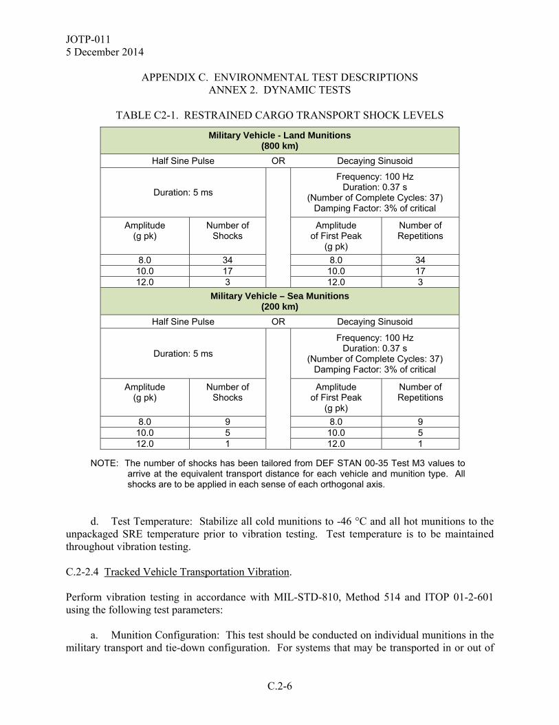
JOTP-011 5 December 2014
APPENDIX C. ENVIRONMENTAL TEST DESCRIPTIONS
ANNEX 2. DYNAMIC TESTS
C.2-6
TABLE C2-1. RESTRAINED CARGO TRANSPORT SHOCK LEVELS
Military Vehicle - Land Munitions (800 km)
Half Sine Pulse OR Decaying Sinusoid
Duration: 5 ms
Frequency: 100 Hz Duration: 0.37 s
(Number of Complete Cycles: 37) Damping Factor: 3% of critical
Amplitude (g pk)
Number of Shocks
Amplitude of First Peak
(g pk)
Number of Repetitions
8.0 34 8.0 34 10.0 17 10.0 17 12.0 3 12.0 3
Military Vehicle – Sea Munitions (200 km)
Half Sine Pulse OR Decaying Sinusoid
Duration: 5 ms
Frequency: 100 Hz Duration: 0.37 s
(Number of Complete Cycles: 37) Damping Factor: 3% of critical
Amplitude (g pk)
Number of Shocks
Amplitude of First Peak
(g pk)
Number of Repetitions
8.0 9 8.0 9 10.0 5 10.0 5 12.0 1 12.0 1
NOTE: The number of shocks has been tailored from DEF STAN 00-35 Test M3 values to
arrive at the equivalent transport distance for each vehicle and munition type. All shocks are to be applied in each sense of each orthogonal axis.
d. Test Temperature: Stabilize all cold munitions to -46 °C and all hot munitions to the unpackaged SRE temperature prior to vibration testing. Test temperature is to be maintained throughout vibration testing. C.2-2.4 Tracked Vehicle Transportation Vibration. Perform vibration testing in accordance with MIL-STD-810, Method 514 and ITOP 01-2-601 using the following test parameters: a. Munition Configuration: This test should be conducted on individual munitions in the military transport and tie-down configuration. For systems that may be transported in or out of

JOTP-011 5 December 2014
APPENDIX C. ENVIRONMENTAL TEST DESCRIPTIONS
ANNEX 2. DYNAMIC TESTS
C.2-7
the transport container, the test duration should be split with half of the test duration packaged in the transport container and half of the test duration unpackaged. b Test Level: This environment can be addressed by the vibration profiles in MIL-STD-810, Method 514 and ITOP 01-2-601 using a duration equivalent to the distance specified in the LCEP. c. Test Duration: The vibration should be conducted for a test duration equivalent to the minimum of 250 km or 2.5% of the distance specified in AECTP 100, Annex E, Appendix 1, for Land Vehicle Mounted Missile. d. Test Temperature: Stabilize all cold munitions to -46 °C and all hot munitions to the unpackaged SRE temperature prior to vibration testing. Test temperature is to be maintained throughout vibration testing. C.2-3 MILITARY SEA TRANSPORTATION DYNAMICS. C.2-3.1 Shipboard Vibration. Perform shipboard vibration of munitions in accordance with MIL-STD-810, Method 528 using the following test parameters: a. Munition Configuration: Packaged. b. Test Level: Conduct testing per MIL-STD-810, Method 528. c. Test Duration: This test should be conducted for one hour per axis. d. Test Temperature: Stabilize all cold munitions to -34 °C and all hot munitions to the appropriate packaged or unpackaged SRE temperature prior to testing. Test temperature is to be maintained throughout testing. C.2-3.2 Shipboard Shock (UNDEX). Perform UNDEX testing in accordance with MIL-S-901 using the following test parameters: a. Munition Configuration: Packaged. b. Test Level: Test parameters are to be determined by National Authority to ensure Safe for Disposal requirements are met. Guidance can be found in NATO publications ANEP-43, STANAG 4549 and STANAG 4150.
JOTP-011 5 December 2014
APPENDIX C. ENVIRONMENTAL TEST DESCRIPTIONS
ANNEX 2. DYNAMIC TESTS
C.2-8
c. Test Temperature: Temperature condition the test munitions prior to, and during shock testing. Stabilize at +21 °C. d. This test should be conducted as a non-sequential test on a single tactical transportation package if the criteria is ‘safe for disposal’, or during the LCEP life cycle test sequence on selected munitions if the criteria is ‘safe for use’. C.2-4 LOGISTIC AIR TRANSPORTATION DYNAMICS – MILITARY. Military Air Transportation Dynamics addresses the mechanical environments that may be encountered during military transportation by fixed wing aircraft (propeller and jet) and helicopters. All tests under these sections must be completed in order to satisfy the S3 objectives for Military Air Transportation unless the mode of transportation is not applicable to the munition under test. C.2-4.1 Fixed Wing Aircraft Cargo Transportation Vibration. Fixed Wing Aircraft Transportation includes both Turboprop and Jet Aircraft Vibration as described in the following paragraphs. C.2-4.1.1 Fixed Wing Turboprop Aircraft Transportation Vibration. Perform vibration testing in accordance with MIL-STD-810, Method 514 using the following test parameters: a. Munition Configuration: Packaged. b. Test Level: MIL-STD-810, Method 514, Annex C, for ‘Propeller Aircraft’ for C130K (4-blade, f0=68 Hz) and C130J (6 blade, f0=102 Hz), with L0 = 1.2 g2/Hz for f0. Other aircraft types may be added if their fundamental blade passing frequencies (f0 component) are known. c. Test Duration: The test should be conducted for a total test duration equivalent to the flight duration specified in AECTP 100, Annex E, Appendix 1 for transportation by ‘Turboprop Aircraft’ for either Land Vehicle Mounted Missiles or Sea Launched Missiles. Based on the current versions of AECTPs 100 and MIL-STD-810, the test duration is one hour per axis as calculated in Table A-3. The test duration for a stated axis should be split such that each set of blade passing frequencies are addressed equally. (For C130 only, this would require the total test duration to be divided equally between the two blade passing frequencies of 68 Hz and 102 Hz). d. Test Temperature: Temperature condition the test munitions prior to, and during vibration testing. Stabilize all cold munitions to -46 °C, and all hot munitions to the packaged SRE temperature.
JOTP-011 5 December 2014
APPENDIX C. ENVIRONMENTAL TEST DESCRIPTIONS
ANNEX 2. DYNAMIC TESTS
C.2-9
C.2-4.1.2 Fixed Wing Jet Aircraft Transportation Vibration. Perform vibration testing in accordance with MIL-STD-810, Method 514 using the following test parameters: a. Munition Configuration: Packaged. b. Test Level: MIL-STD-810, Method 514, Annex C for ‘Jet Aircraft Cargo’. c. Test Duration: The test should be conducted for a total test duration equivalent to the flight duration specified in AECTP 100, Annex E, Appendix 1 for transportation by ‘Jet Aircraft’ for either Land Vehicle Mounted Missiles or Sea Launched Missiles. Since the test level is for the take-off environment only, the test duration is based on the number of flights. To derive appropriate test durations, apply an average flight time of 10 hours per transport to determine the appropriate number of take-off events. Based on the current versions of AECTPs 100 and MIL-STD-810, the test duration is 10 minutes per axis for land based munitions and 5 minutes per axis for sea based munitions as calculated in Table A-3. d. Test Temperature: Temperature condition the test munitions prior to, and during vibration testing. Stabilize all cold munitions to -46 °C, and all hot munitions to the packaged SRE temperature. C.2-4.2 Helicopter Cargo Transportation Vibration. This test is applicable to small land and sea munitions for which transport as cargo on a Rotary Wing Aircraft is a plausible mode of transport. Perform vibration testing in accordance with MIL-STD-810, Method 514 using the following test parameters: a. Munition Configuration: Packaged. b. Test Level: MIL-STD-810, Method 514, Annex C for ‘Helicopter Cargo’. Fundamental blade passing frequencies (f1 component) of 11 Hz, 17 Hz, and 21 Hz should be used to address most transport helicopter types. Other aircraft types may be added if their fundamental blade passing frequencies (f1 component) are known. c. Test Duration: The test should be conducted for a total test duration equivalent to the flight duration specified in AECTP 100, Annex E, Appendix 1 for transportation by ‘Helicopter’ for either Land Vehicle Mounted Missiles or Sea Launched Missiles. Based on the current versions of AECTPs 100 and MIL-STD-810, the test duration for land based munitions is 3.33 hours/axis and 50 minutes/axis for sea based munitions as calculated in Table A-3. The total test duration for a stated axis should be split such that each set of blade passing frequencies are addressed equally.

JOTP-011 5 December 2014
APPENDIX C. ENVIRONMENTAL TEST DESCRIPTIONS
ANNEX 2. DYNAMIC TESTS
C.2-10
d. Test Temperature: Temperature condition the test munitions prior to, and during vibration testing. Stabilize all cold munitions to -46 °C, and all hot munitions to the packaged SRE temperature. C.2-5 TACTICAL COMBAT PLATFORM DYNAMICS. Tactical Combat Platform Dynamics addresses the mechanical environments that may be encountered during deployment on the tactical combat platform. It is recommended that actual environments be measured and used to develop vibration and shock test criteria in accordance with MIL-STD-810, Method 514, Annex F. C.2-5.1 Land Based Munitions Tactical Dynamics. C.2-5.1.1 Launch Vehicle Restrained Cargo Transport Vibration. Perform vibration testing in accordance with MIL-STD-810, Method 514 using the following test parameters: a. Test Configuration: Attach the munition to the vibration exciter in the restrained cargo transport configuration. b. Test Level: Vibration test each munition in accordance with the vibration test schedule representative of the munition location on the platform. Vibration specification development guidance is provided in MIL-STD-810, Method 514, Annex F. c. Test Duration: The required test duration is equivalent to 5000 km of launch vehicle transport. d. Test Temperature: Temperature condition the test munitions prior to, and during vibration testing. Stabilize all cold munitions to -46 °C, and all hot munitions to the packaged SRE temperature. C.2-5.1.2 Launch Vehicle Restrained Cargo Transport Shock. These shocks should be similar in content to the Restrained Cargo Transport Shock test of paragraph C.2-2.2 and need not be repeated. Use measured data with the munition on the tactical platform to verify the levels. C.2-5.1.3 Tactical Launcher Vibration. Perform vibration testing in accordance with MIL-STD-810, Method 514 using the following test parameters:
JOTP-011 5 December 2014
APPENDIX C. ENVIRONMENTAL TEST DESCRIPTIONS
ANNEX 2. DYNAMIC TESTS
C.2-11
a. Test Configuration: Attach the munition to the vibration exciter in all relevant tactical launcher transport or deployment configurations. b. Test Level: Vibration test each munition in accordance with the vibration test schedule representative of the munition location on the platform. Vibration specification development guidance is provided in MIL-STD-810, Method 514, Annex F. c. Test Duration: The required test duration is dependent upon the munition life cycle but should be equivalent to at least 1000 km of transport in this configuration. d. Test Temperature: Temperature condition the test munitions prior to, and during vibration testing. Stabilize all cold munitions to -46 °C, and all hot munitions to the SRE temperature. C.2-5.1.4 Tactical Launcher Shocks. Perform shock testing in accordance with MIL-STD-810, Method 516 using the following test parameters: a. Test Configuration: Attach the munition to the shock exciter in all relevant tactical launcher transport or deployment configurations. b. Test Level: Shock test each munition to a tailored shock response spectrum (SRS) representative of the launcher location on the platform(s). SRS specification development guidance is provided in MIL-STD-810, Method 514, Annex F. This test may be eliminated if determined to be sufficiently benign compared to other dynamic environments. c. Number of Shocks: The required number of shocks is determined by the LCEP. d. Test Temperature: Temperature condition the test munitions prior to, and during shock testing. Stabilize all cold munitions to -46 °C, and all hot munitions to the SRE temperature. C.2-5.1.6 Adjacent Munition Firing Shocks. Perform shock testing in accordance with MIL-STD-810, Method 514 using the following test parameters: a. Test Configuration: Attach the munition to the shock exciter in the launch configuration. b. Test Level: Shock test each munition to a tailored shock response spectrum (SRS) representative of the launcher location on the platform(s). SRS specification development guidance is provided in MIL-STD-810, Method 514, Annex F. This test may be eliminated if
JOTP-011 5 December 2014
APPENDIX C. ENVIRONMENTAL TEST DESCRIPTIONS
ANNEX 2. DYNAMIC TESTS
C.2-12
determined to be sufficiently benign compared to other dynamic environments. c. Number of Shocks: The required number of shocks is determined by the LCEP. d. Test Temperature: Temperature condition the test munitions prior to, and during shock testing. Stabilize all cold munitions to -46 °C, and all hot munitions to the SRE temperature. C.2-5.2 Sea Based Munitions Tactical Dynamics. C.2-5.2.1 Tactical Ship and Underwater Launch Configuration Vibration. Perform vibration testing in accordance with MIL-STD-810, Method 528 using the following test parameters: a. Munition Configuration: Attach the munition to the vibration exciter in all relevant tactical launcher transport or deployment configurations. b. Test Level: MIL-STD-810, Method 528. c. Test Duration: The test should be conducted for the default duration of one hour per axis. d. Test Temperature: Temperature condition the test munitions prior to, and during vibration testing. Stabilize all cold munitions to -34 °C, and all hot munitions to the unpackaged SRE. Test underwater launched munitions at standard ambient conditions. C.2-5.2.2 Tactical Ship Adjacent Munition Firing Shocks. Perform shock testing in accordance with MIL-STD-810, Method 516 using the following test parameters: a. Test Configuration: Attach the munition to the shock exciter in the launch configuration. b. Test Level: Shock test each munition to a tailored shock response spectrum (SRS) representative of the launcher location on the platform(s). SRS specification development guidance is provided in MIL-STD-810, Method 514, Annex F. This test may be eliminated if determined to be sufficiently benign compared to other dynamic environments. c. Number of Shocks: The required number of shocks is determined by the LCEP. d. Test Temperature: Temperature condition the test munitions prior to, and during shock testing. Stabilize all cold munitions to -34 °C, and all hot munitions to the SRE temperature. Test
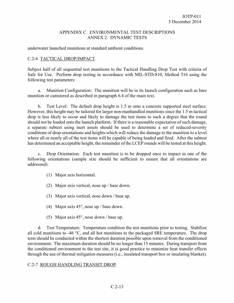
JOTP-011 5 December 2014
APPENDIX C. ENVIRONMENTAL TEST DESCRIPTIONS
ANNEX 2. DYNAMIC TESTS
C.2-13
underwater launched munitions at standard ambient conditions. C.2-6 TACTICAL DROP/IMPACT. Subject half of all sequential test munitions to the Tactical Handling Drop Test with criteria of Safe for Use. Perform drop testing in accordance with MIL-STD-810, Method 516 using the following test parameters: a. Munition Configuration: The munition will be in its launch configuration such as bare munition or canistered as described in paragraph 6.4 of the main text. b. Test Level: The default drop height is 1.5 m onto a concrete supported steel surface. However, this height may be tailored for larger non-manhandled munitions since the 1.5 m tactical drop is less likely to occur and likely to damage the test items to such a degree that the round should not be loaded onto the launch platform. If there is a reasonable expectation of such damage, a separate subtest using inert assets should be used to determine a set of reduced-severity conditions of drop orientations and heights which will reduce the damage to the munition to a level where all or nearly all of the test items will be capable of being loaded and fired. After the subtest has determined an acceptable height, the remainder of the LCEP rounds will be tested at this height. c. Drop Orientation: Each test munition is to be dropped once to impact in one of the following orientations (sample size should be sufficient to ensure that all orientations are addressed): (1) Major axis horizontal. (2) Major axis vertical, nose up / base down. (3) Major axis vertical, nose down / base up. (4) Major axis 45°, nose up / base down. (5) Major axis 45°, nose down / base up. d. Test Temperature: Temperature condition the test munitions prior to testing. Stabilize all cold munitions to -46 °C, and all hot munitions to the packaged SRE temperature. The drop tests should be conducted within the shortest duration possible upon removal from the conditioned environment. The maximum duration should be no longer than 15 minutes. During transport from the conditioned environment to the test site, it is good practice to minimize heat transfer effects through the use of thermal mitigation measures (i.e., insulated transport box or insulating blanket). C.2-7 ROUGH HANDLING TRANSIT DROP.
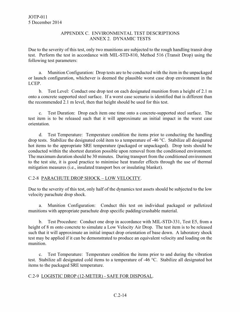
JOTP-011 5 December 2014
APPENDIX C. ENVIRONMENTAL TEST DESCRIPTIONS
ANNEX 2. DYNAMIC TESTS
C.2-14
Due to the severity of this test, only two munitions are subjected to the rough handling transit drop test. Perform the test in accordance with MIL-STD-810, Method 516 (Transit Drop) using the following test parameters:
a. Munition Configuration: Drop tests are to be conducted with the item in the unpackaged or launch configuration, whichever is deemed the plausible worst case drop environment in the LCEP.
b. Test Level: Conduct one drop test on each designated munition from a height of 2.1 m onto a concrete supported steel surface. If a worst case scenario is identified that is different than the recommended 2.1 m level, then that height should be used for this test. c. Test Duration: Drop each item one time onto a concrete-supported steel surface. The test item is to be released such that it will approximate an initial impact in the worst case orientation. d. Test Temperature: Temperature condition the items prior to conducting the handling drop tests. Stabilize the designated cold item to a temperature of -46 °C. Stabilize all designated hot items to the appropriate SRE temperature (packaged or unpackaged). Drop tests should be conducted within the shortest duration possible upon removal from the conditioned environment. The maximum duration should be 30 minutes. During transport from the conditioned environment to the test site, it is good practice to minimise heat transfer effects through the use of thermal mitigation measures (i.e., insulated transport box or insulating blanket). C.2-8 PARACHUTE DROP SHOCK – LOW VELOCITY. Due to the severity of this test, only half of the dynamics test assets should be subjected to the low velocity parachute drop shock. a. Munition Configuration: Conduct this test on individual packaged or palletized munitions with appropriate parachute drop specific padding/crushable material. b. Test Procedure: Conduct one drop in accordance with MIL-STD-331, Test E5, from a height of 8 m onto concrete to simulate a Low Velocity Air Drop. The test item is to be released such that it will approximate an initial impact drop orientation of base down. A laboratory shock test may be applied if it can be demonstrated to produce an equivalent velocity and loading on the munition. c. Test Temperature: Temperature condition the items prior to and during the vibration test. Stabilize all designated cold items to a temperature of -46 °C. Stabilize all designated hot items to the packaged SRE temperature. C.2-9 LOGISTIC DROP (12-METER) - SAFE FOR DISPOSAL.

JOTP-011 5 December 2014
APPENDIX C. ENVIRONMENTAL TEST DESCRIPTIONS
ANNEX 2. DYNAMIC TESTS
C.2-15
Subject three (3) test munitions to the Logistic Drop Test with a criterion of Safe for Disposal. Perform drop testing in accordance with MIL-STD-2105 using the following test parameters: a. Munition Configuration: The munitions are tested in the packaged configuration unless the potential exists for munitions to be handled out of the shipping container while on naval vessels. In this case the munitions are required to be tested in the unpackaged mode. b. Test Level: One drop of 12 m onto a concrete supported steel surface. c. Drop Orientations: Each test munition to impact in one of the following orientations. (Note sample size should be sufficient to ensure that all orientations are addressed): (1) Major axis horizontal (2) Major axis vertical, nose up / base down (3) Major axis vertical, nose down / base up d. Test Temperature: Ambient C.2-10 MUNITION FLIGHT DYNAMICS. Munition Flight Dynamics addresses the mechanical environments that may be encountered during missile and rocket launch and flight. Test levels are to be tailored from measured data. C.2-10.1 Launch Shock. Launch shock should be conducted in accordance with MIL-STD-810, Methods 516 and 525 appropriate; however, tailored test levels based on measured data will normally be used. Replicate all shocks occurring within the safe separation zone. This may include shocks caused by safe entry into water or multi stage rocket motor separation / ignition events. Derive test severities in accordance with MIL-STD-810, Method 514, Annex F. a. Test Configuration. Attach the munition to the shock exciter as appropriate. b. Test Level. The tailored test levels are typically specified as either a half-sine shock pulse or a shock response spectra in accordance with Method 516 (SRS).
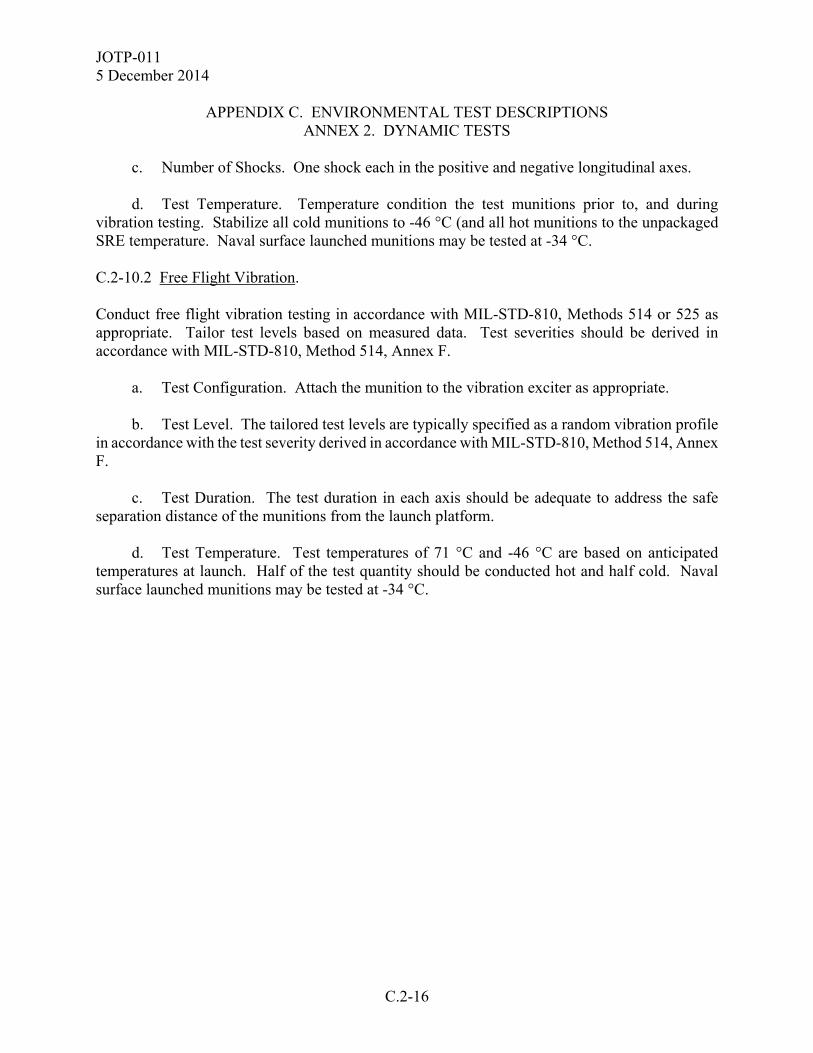
JOTP-011 5 December 2014
APPENDIX C. ENVIRONMENTAL TEST DESCRIPTIONS
ANNEX 2. DYNAMIC TESTS
C.2-16
c. Number of Shocks. One shock each in the positive and negative longitudinal axes. d. Test Temperature. Temperature condition the test munitions prior to, and during vibration testing. Stabilize all cold munitions to -46 °C (and all hot munitions to the unpackaged SRE temperature. Naval surface launched munitions may be tested at -34 °C. C.2-10.2 Free Flight Vibration. Conduct free flight vibration testing in accordance with MIL-STD-810, Methods 514 or 525 as appropriate. Tailor test levels based on measured data. Test severities should be derived in accordance with MIL-STD-810, Method 514, Annex F. a. Test Configuration. Attach the munition to the vibration exciter as appropriate. b. Test Level. The tailored test levels are typically specified as a random vibration profile in accordance with the test severity derived in accordance with MIL-STD-810, Method 514, Annex F. c. Test Duration. The test duration in each axis should be adequate to address the safe separation distance of the munitions from the launch platform. d. Test Temperature. Test temperatures of 71 °C and -46 °C are based on anticipated temperatures at launch. Half of the test quantity should be conducted hot and half cold. Naval surface launched munitions may be tested at -34 °C.

JOTP-011 5 December 2014
APPENDIX D. OPERATING TEST DESCRIPTIONS
D-1
This Appendix provides descriptions of all of the firing and operating tests required in the S3 Test Programs included in Appendix B. Rationales for these tests are provided in Appendix A.
JOTP-011 5 December 2014
APPENDIX D. OPERATING TEST DESCRIPTIONS
D-2
(This page is intentionally blank.)
JOTP-011 5 December 2014
APPENDIX D. OPERATING TEST DESCRIPTIONS
ANNEX 1. FIRING SAFETY TESTS
D.1-1
The firing safety tests are performed upon completion of the sequential environmental tests. All of these tests are conducted remotely with the munition temperature conditioned to the appropriate temperature. The low-temperature test items are to be temperature stabilized to -46 °C prior to performing the firing tests. The high-temperature test items are to be temperature stabilized to 63 °C or the unpackaged SRE temperature, whichever is higher, prior to performing the firing tests. Firing tests should be conducted within the shortest duration possible upon removal from the conditioned environment. The maximum duration should be 30 minutes. D.1-1 DYNAMIC FIRING. The dynamic firing tests are conducted on an instrumented firing range to demonstrate that the munition: is safe to launch (does not eject hazardous debris or detonate upon ignition), safely separates from the launch point/tube, and travels at and explosively functions at trajectories which cause no additional hazards to the firing crew. Performance data shall be recorded but not used as acceptance criteria except as related to safety. Additional data are collected to support the Weapon Danger Area and Health Hazard Analyses. a. Record launch, early flight, and air burst or target impact portions of the flight with high-speed cameras, radars, or infrared sensors. Record fire control and ground signals. Obtain air burst data, munition position and velocity data and, as applicable, miss distance data for these firings. b. Health Hazard Analysis. Collect applicable health hazard data as required for the intended platform(s). Consider acoustic energy, blast overpressure, toxic gases, thermal effects, radiance, and launch shock (recoil) data in accordance with Appendix H, Annex 2. These data are collected at positions to be occupied by the launch crew. Also collect these data outside of the firing position to define the launch space that is unsafe for occupancy during firings. c. Weapon Danger Area Analysis. Plot all munition impact coordinates (measured during successful and unsuccessful dynamic firings) on weapon danger area profiles. Develop statistical density distributions of the impacts for assessment of the specified weapon danger area profiles and the firing range safety profiles. Use warhead arming and functioning data from the unmanned firings and the warhead arena trials (Appendix D, Annex 2, Paragraph D.2-4), combined with munition impact data and weapon danger area profiles, to assess launch area safety and downrange safety, including friendly soldier overflight safety, as applicable. Further guidance may be found in STANAG 2240, Allied Range Safety Publication 1 (ARSP-1 VOL II) Weapon Danger Areas / Zones For Unguided Weapons For Use by NATO Forces in a Ground Role. d. Launch Debris. Determine launch debris patterns, velocities, sizes, and masses using soft media fragment collection packs and high speed cameras during the dynamic firings. Collect these data outside of the operator’s position to define the launch space that is unsafe for occupancy during firings. D.1-2 FUZE ARMING DISTANCE FIRING.
JOTP-011 5 December 2014
APPENDIX D. OPERATING TEST DESCRIPTIONS
ANNEX 1. FIRING SAFETY TESTS
D.1-2
Fuze arming distance firings are used in combination with warhead arena trials to verify that the no-arm or “minimum arm distance” exceeds the safe separation distance for the item. Detailed guidance may be found in MIL-STD-331. Consider anticipated launch scenarios (e.g., platform velocity, launch attitude, maneuvers) in planning fuze arming tests and analysis. a. Fuzes function in two primary modes: point detonating and air burst, others may include a delay feature. The Projectile Fuze Arming Distance procedure of MIL-STD-331 Test D2 is used to determine the minimum arm distance for point detonating and delay type fuzing systems. For an air burst type fuzing system, the minimum arm distance is determined using the Time to Air Burst test approach in MIL-STD-331 Test D3. b. Fire items at an instrumented range and record launch, early flight, and air burst or target impact portions of the flight with high-speed cameras, radars, or infrared sensors. Record fire control and ground signals, as well as target configuration and distance from launch point. Obtain time to burst data, munition position, and velocity data and as applicable, miss distance data for these firings. D.1-3 WARHEAD FUZE SENSITIVITY. Fuze sensitivity tests determine whether or not the fuze functions on impact with light brush or other obstruction in close proximity to the firing crew. A fly-through panel is placed at predetermined distances to simulate obstructions. MIL-STD-331 provides details on this and other fuze sensitivity tests. Some of the munitions may be fired at extreme temperatures.

JOTP-011 5 December 2014
APPENDIX D. OPERATING TEST DESCRIPTIONS
ANNEX 2. COMPONENT LEVEL OPERATING TESTS
D.2-1
Munitions that have undergone sequential environmental testing require component level assessment of energetic and pressure vessel components in order to estimate the probability and effect of catastrophic failure during operational use. In addition to warheads and rocket motors, other items may require these tests. Examples are gas generators, pressure vessels, or thermal beacons which could burst during operation and present a hazard to personnel. See Appendix A, Annex 2 for additional background and rationale. D.2-1 ROCKET MOTOR STATIC FIRING. Static firings are conducted to measure the internal operating pressure of rocket motors during operational use. Guidance for this test may be found in ITOP 05-2-500. a. The items should be temperature conditioned to -46 °C and the higher of +63 °C or the unpackaged SRE temperature. b. Mount the item in an appropriate static firing stand. c. Instrument item with pressure, force, strain, temperature, and vibration transducers as required. d. Static fire item and record internal operating pressure, thrust, strain, temperature, and acceleration parameters as required. e. Perform a post test inspection of the motor to check for ‘burn-through’ of rocket motor case, heat damage to nozzle/venturi and damage to thermal barrier (if present). f. The probability of motor case rupture is estimated using the static firing and burst test pressure data in the statistical method presented in Appendix G. g. Margins of safety must be demonstrated between measured test data and measured or analytical failure modes. If measured variable data indicate only small margins of safety exist, further investigation or testing may be required. D.2-2 ROCKET MOTOR BURST TESTS. Burst tests are conducted to measure the pressure required to burst the rocket motor case under conditions similar to actual firing. These tests are conducted at ambient temperature using the hydrostatic burst test method described below. a. Position the item in an appropriate restraining fixture and instrument with pressure transducers to record the internal operating pressure.
JOTP-011 5 December 2014
APPENDIX D. OPERATING TEST DESCRIPTIONS
ANNEX 2. COMPONENT LEVEL OPERATING TESTS
D.2-2
b. Fill the rocket motor completely with an inert test fluid such as water. c. Using a high-pressure pump or a bursting diaphragm arrangement, rapidly pressurize the vessel until it bursts. Note that the fluid line should have provisions for an additional volume of test fluid to be pumped into the vessel to account for motor case expansion. The rate of pressurization shall approximate the pressurization rate of a normally fired motor. d. Perform a post test inspection of the motor case to check for indications of structural failure. e. The probability of motor case rupture is estimated using the static firing and burst test pressure data in the statistical method presented in Appendix G. Further guidance on bursts test methods may be found in ITOP 05-2-621. D.2-3 OTHER PRESSURE VESSELS. Other types of pressure vessels (gas generators, high pressure pneumatic vessels, etc.) in the munition are hydrostatically burst tested to assess personnel hazards and determine safety design margins. Compare burst pressures to determine the safety margin and the likelihood of burst. Determine the fragment size, the velocity, and the fragment distribution to assess the hazard in the event of burst during service use of the vessel. D.2-4 WARHEAD ARENA TRIALS. Warhead arena trials are performed to determine safe separation distances and range safety parameters. These trials should be conducted with non-sequential, factory fresh warheads unless it can be shown that exposure to thermal and dynamic stresses in the Sequential Environmental Test Sequence results in an increase in fragmentation distance. Guidance for this test can be found in ITOP 04-2-813. a. Perform this test on four individual warheads at ambient temperature. b. Warhead arena trials require the use of the warhead only. However, the tester should evaluate whether components directly attached to the warhead or in the immediate area of the warhead, either by design or by inadvertent action, could significantly affect the warhead's fragment dispersion pattern. c. Place the item in the instrumented arena and detonate the warhead. d. Determine warhead fragment size, velocity, mass, spatial distribution, and levels of noise and blast pressure.
JOTP-011 5 December 2014
APPENDIX D. OPERATING TEST DESCRIPTIONS
ANNEX 2. COMPONENT LEVEL OPERATING TESTS
D.2-3
D.2-5 OTHER ENERGETICS. Other types of energetic materials in the munition (e.g., thermal batteries, safe and arming devices, squibs) are static fired to assess functionality with respect to safe operation. Ten of each type of energetic device in the munition shall be static fired. D.2-6 OTHER SAFETY CRITICAL COMPONENTS. Conduct operational tests on safety critical components to the extent required to identify potentially unsafe operation. Ten of each safety critical component shall be operationally tested.
JOTP-011 5 December 2014
APPENDIX D. OPERATING TEST DESCRIPTIONS
ANNEX 2. COMPONENT LEVEL OPERATING TESTS
D.2-4
(This page is intentionally blank.)
JOTP-011 5 December 2014
APPENDIX E. BREAKDOWN TEST AND CRITICAL ANALYSIS (BTCA)
E-1
This document was developed within the international community and is written with references to both US and NATO test procedures to provide a framework for international procurement and test programs. Table I2-1 (Appendix I, Annex 2) provides cross reference of similar national and international test standards. The following BTCA procedures must only be conducted by suitably qualified and experienced personnel. E.1. GENERAL INSPECTION. Prior to disassembly for BTCA, conduct a thorough review of Level 1 (basic visual) and Level 2 (radiography) inspection results and non-functioning test results obtained throughout the sequential environmental trial. Any anomaly should be carefully considered with regard to the safety of the munition disassembly and BTCA processes. E.2. BREAKDOWN AND ANALYSIS REQUIREMENTS. E.2.1 APPLICABILITY. The following tests are broadly applicable to warheads (main charge and firing train), rocket motors (main charge, igniter, intermediaries) and pyrotechnic devices (actuators, tracers, etc.). E.2.2 REQUIREMENT CONSIDERATIONS. The exact requirements for BTCA need to be determined on a case by-case basis taking into consideration the degree of novelty and/or complexity of the munition. They will be determined by known failure modes and life limiting factors for comparable munitions. E.2.3 BASELINE TEST CONSIDERATIONS. Prior to commencement of all trials, at least one munition from the same batch/lot as those undergoing the sequential environmental trial should be disassembled and analyzed to identify potential failure modes that may occur. This sets the baseline for comparison against the environmentally stressed munitions. There should also be baseline munitions for the functioning (dynamic and static firing) tests. It may also be possible to use the results from material Qualification tests (to STANAG 4170) for baseline purposes, or data from material manufacturers batch/lot acceptance tests provided these give data equivalent to that from the Qualification tests. Furthermore, firing data from development trials may be used for baseline purposes provided the munition is of the same build standard as the test munitions and provides the required data. However, it should be noted that none of these latter options will permit comparison against the physical condition of the munitions following the sequential environmental trial.

JOTP-011 5 December 2014
APPENDIX E. BREAKDOWN TEST AND CRITICAL ANALYSIS (BTCA)
E-2
E.2.4 TEST CONSISTENCY CONSIDERATIONS. It is essential to ensure that the same test procedures used to determine the baseline properties of materials are used during BTCA. E.2.5 CONTAMINATION CONSIDERATIONS. During disassembly and material extraction, care must be taken to ensure that the extracted samples do not become contaminated (by structural materials or other matter) and/or physically damaged/changed (e.g., compressed, cracked, abraded). E.2.6 FUNCTIONAL TEST CONSIDERATIONS. Small items such as igniters, initiators, squibs, etc. pose particular difficulties during disassembly, and it may not be possible to extract sufficient material without damaging the material contained within. In such cases it is acceptable to perform just visual and radiographic inspection followed by functioning tests (at extremes of service temperature). This should include electrical resistance checks and tests performed during lot acceptance such as performance tests during functioning. In some cases it may be possible to extract sufficient material to perform small scale tests such as volatile content determination or differential scanning calorimetry (DSC). E.2.7 BTCA TEST REQUIREMENTS. The aspects below are provided as an indication of the types of testing required. E.2.7.1 Inspection and Disassembly. a. Physical integrity and dimensional checks of the munition, sub-systems, energetic materials, and structural materials. This can be achieved through visual inspection (including photography as required), radiography, Computed Tomography (CT) Scan, Dye Penetrant, Bore-scope (for rocket motor conduits), Ultrasonic inspection, and/or Fluoroscopy both prior to, and following disassembly. Some techniques may be more applicable to structural materials which must also be assessed. Dimensional checks should assess physical dimensions and mass of the complete munition, sub-systems and energetic materials to demonstrate compliance with specifications/drawings. b. During disassembly, pay particular attention to signs of cracking, surface crystallization/dusting (e.g., Ammonium Perchlorate in rocket motors and Nitramines in warheads), debonding/delamination (e.g., thermal liners and inhibitors for rocket motors), exudation (e.g., energetic and inert plasticizers in rocket motors), corrosion, discoloration, wear, missing components and other damage.
JOTP-011 5 December 2014
APPENDIX E. BREAKDOWN TEST AND CRITICAL ANALYSIS (BTCA)
E-3
c. Plastics, rubbers, foams, seals etc. should be examined for signs of degradation or uptake of plasticizer. ‘O’ rings should be examined for compression set and that they still meet their specification requirements. E.2.7.2 Chemical Tests. a. Chemical composition, including total volatile matter and moisture content, must be assessed to demonstrate compliance with specifications/drawings. b. Chemical stability must be assessed for all energetic materials, although the tests used will be material dependant. The vacuum stability test is particularly applicable for main charge explosives. Chemical stabilizer depletion testing (to AOP-48) is applicable for nitrate-ester propellants, with a preference for multi-temperature ageing since this gives both stabilizer content and chemical kinetics. E.2.7.3 Compatibility Tests. a. Chemical/explosive compatibility between all components of construction with the explosives they will be in communication with (both in physical contact and by gas/vapor path) should have been assessed during material qualification and/or design of the munition. This compatibility data shall be presented as a matrix that lists the materials, and for each explosive declares whether there is communication or not with evidence to support the claim of compatibility where communication is expected. b. During BTCA, any material incompatibilities and/or migration of explosive species are likely to become evident during inspection. Any such anomalies observed shall be noted and assessed further to address whether the munition remains safe as defined AAS3P-1. An example is the migration of energetic plasticizers into thermal liners in rocket motors which may render the thermal liner incapable of fulfilling its intended design role and give rise to an unsafe situation. E.2.7.4 Physical Properties – Explosives. a. Assessment of flow properties and particle size distribution for granular materials (such as granular propellants and some pyrotechnic compositions), checking for coagulation of granular materials, ‘slump’ (particularly in propellants), bulk cracking, and surface cracking/crazing. b. Thermal analysis methods, especially Differential Scanning Calorimetry, are useful tools that may indicate changes in the material over time and are particularly suited to subsequent comparison during In-Service Surveillance. They are applicable to most explosive materials, especially pyrotechnics, since they can be performed on small samples of material.
JOTP-011 5 December 2014
APPENDIX E. BREAKDOWN TEST AND CRITICAL ANALYSIS (BTCA)
E-4
E.2.7.5 Mechanical Properties. Mechanical properties (such as tensile/compressive/ shear strength and hardness) of explosive materials must be assessed at the full range of working temperatures for the munition. It will also be necessary to test structural materials at temperature extremes for safety critical items, such as rocket motor cases, in order to verify design safety margins. Typical methods will include uniaxial tensile testing to STANAG 4506, Dynamic Mechanical Thermal Analysis (DMTA) to STANAG 4540 and burst overpressure tests on rocket motor cases (although it may prove difficult to conduct these as part of BTCA). It may also be necessary to assess fatigue crack growth for some structural materials. The types of testing will ultimately be determined by the type of material being tested. E.2.7.6 Hazard Properties. a. Repetition of the small scale tests to assess hazard properties must be undertaken. These may include, but are not limited to, methods to determine ease of initiation by impact, friction and electrical spark, along with temperature of ignition. Explosive material testing and assessment should be conducted in accordance with STANAG 4170 and AOP-7. b. Normally the small scale tests will be sufficient but larger scale tests may also be required if an issue is identified. The exact methods used would depend upon the type and quantity of material available for the tests but may include ‘gap tests’ and tests to assess Velocity of Detonation. However, they may ultimately require full scale (i.e., complete round) tests to assess the IM properties of the munition following environmental exposure. E.2.7.7 Electrical Components. a. Where the munition contains electrical sub-assemblies (e.g., electronic safe/arm device, weapon controller, seeker) these should be removed during BTCA for inspection and functional checks. Functional checks should be performed initially on the initial sub-assembly, using the factory test specification. Where this is not possible or does not allow full testing, then the sub-assembly may require further disassembly to permit such testing. b. Following this, full disassembly should be conducted for detailed component level inspection. Specific points to observe are broken/loose joints (connectors and solder), damaged/broken components, damaged/broken circuit board tracks, abraded/broken cables/wiring, corrosion, dendritic growth (e.g., ‘tin whiskers’), condition of ‘potting’ compound (if present), and burst batteries. c. Electrical resistance of igniters/EIDs (EEDs) should be checked, and EIDs (EEDs) functioned using a normal firing pulse.
JOTP-011 5 December 2014
APPENDIX E. BREAKDOWN TEST AND CRITICAL ANALYSIS (BTCA)
E-5
E.2.7.8 Fuze (Mechanical) Components. a. Where the munition contains a mechanical fuze this should be removed during BTCA for inspection where possible. b. If there is any doubt regarding the safe and reliable function of the fuze, or it cannot be demonstrated by alternative means, it may be necessary to carry out tests that simulate the various external stimuli required to arm the fuze (e.g., acceleration, spin). c. The fuze (either armed or safe) should be disassembled to determine its internal physical condition and verify its safe condition.
JOTP-011 5 December 2014
APPENDIX E. BREAKDOWN TEST AND CRITICAL ANALYSIS (BTCA)
E-6
(This page is intentionally blank.)
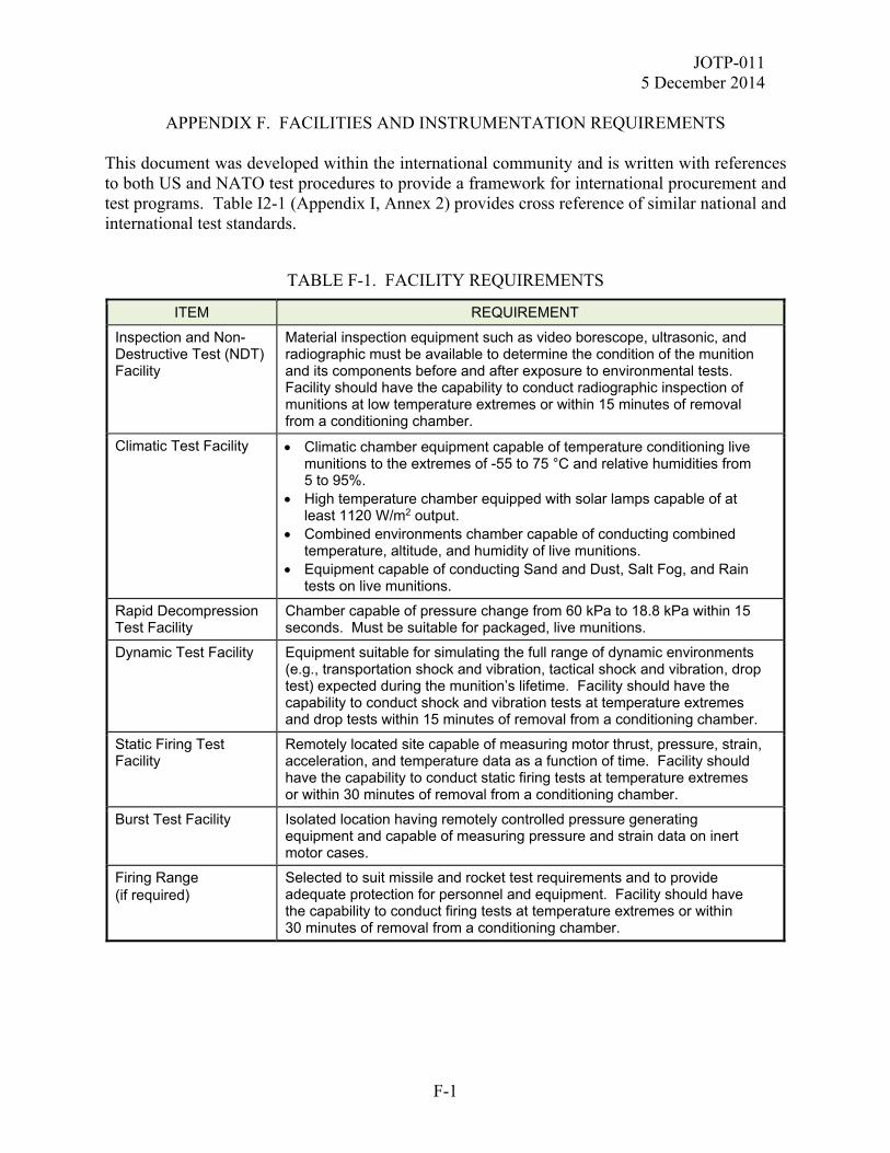
JOTP-011 5 December 2014
APPENDIX F. FACILITIES AND INSTRUMENTATION REQUIREMENTS
F-1
This document was developed within the international community and is written with references to both US and NATO test procedures to provide a framework for international procurement and test programs. Table I2-1 (Appendix I, Annex 2) provides cross reference of similar national and international test standards.
TABLE F-1. FACILITY REQUIREMENTS
ITEM REQUIREMENT
Inspection and Non-Destructive Test (NDT) Facility
Material inspection equipment such as video borescope, ultrasonic, and radiographic must be available to determine the condition of the munition and its components before and after exposure to environmental tests. Facility should have the capability to conduct radiographic inspection of munitions at low temperature extremes or within 15 minutes of removal from a conditioning chamber.
Climatic Test Facility Climatic chamber equipment capable of temperature conditioning live munitions to the extremes of -55 to 75 °C and relative humidities from 5 to 95%.
High temperature chamber equipped with solar lamps capable of at least 1120 W/m2 output.
Combined environments chamber capable of conducting combined temperature, altitude, and humidity of live munitions.
Equipment capable of conducting Sand and Dust, Salt Fog, and Rain tests on live munitions.
Rapid Decompression Test Facility
Chamber capable of pressure change from 60 kPa to 18.8 kPa within 15 seconds. Must be suitable for packaged, live munitions.
Dynamic Test Facility Equipment suitable for simulating the full range of dynamic environments (e.g., transportation shock and vibration, tactical shock and vibration, drop test) expected during the munition’s lifetime. Facility should have the capability to conduct shock and vibration tests at temperature extremes and drop tests within 15 minutes of removal from a conditioning chamber.
Static Firing Test Facility
Remotely located site capable of measuring motor thrust, pressure, strain, acceleration, and temperature data as a function of time. Facility should have the capability to conduct static firing tests at temperature extremes or within 30 minutes of removal from a conditioning chamber.
Burst Test Facility Isolated location having remotely controlled pressure generating equipment and capable of measuring pressure and strain data on inert motor cases.
Firing Range (if required)
Selected to suit missile and rocket test requirements and to provide adequate protection for personnel and equipment. Facility should have the capability to conduct firing tests at temperature extremes or within 30 minutes of removal from a conditioning chamber.

JOTP-011 5 December 2014
APPENDIX F. FACILITIES AND INSTRUMENTATION REQUIREMENTS
F-2
TABLE F-1. FACILITY REQUIREMENTS (CONTINUED)
ITEM REQUIREMENT
Warhead Test Area Test area must have an adequate surface safety danger zone, including overhead air space for open field testing.
Munition Disassembly Facility suitable for disassembly of live munitions for detailed inspection and component level testing.
Energetic Material Extraction (if required)
Equipment suitable for the extraction of energetic material samples for chemical analysis.
Chemistry Laboratory (if required)
Equipment suitable for the conduct of the chemical analysis tests set out in STANAG 4170, AOP-7, and paragraphs E.2.7.2 through E.2.7.6 of Appendix E (BTCA).
Electromagnetic Radiation Test Facility
Facility suitable for the generation of the specified field intensities with an adequate test volume for the test of the munition and launcher as required by the stockpile to launch configuration.
Electrostatic Discharge Test Facility
Facility suitable for the generation of the required ESD environments and large enough for the munition and launcher as required by the stockpile to launch configuration.
Lightning Test Facility Facility capable of conducting the required lightning strike test on live munitions.
Data Collection/Processing Facility
Test data shall be recorded on Digital Recorders for post-test processing. The data processing system shall edit, display, and print out the desired data plot for analysis and reporting purposes.
Video/Photographic Closed circuit video is required for personnel safety to permit observation of munition tests. Video Camera/Recording Systems having a sufficient frame rate to record and playback desired events. High speed digital cameras and/or UV/IR cameras may also be required.

JOTP-011 5 December 2014
APPENDIX F. FACILITIES AND INSTRUMENTATION REQUIREMENTS
F-3
TABLE F-2. MEASUREMENT TOLERANCES
DEVICES FOR MEASURING MEASUREMENT TOLERANCE
Pressure 5 percent of the value or 200 Pa, whichever is greater.
Strain 1 percent of highest expected value
Thrust (Load Cells) 1 percent of highest expected value
Heat Flux 1 percent of highest expected value
Resistance (Low Current Circuit Tester/ Squib Tester)
0.05 ohms
Firing Pulse (Automatic Fire Control System)
As required for the initiation of static fire or burst tests and the automatic sequencing of the data collection systems.
Motor Ignition Events (Video) Frame rate sufficient to record desired event.
Time 1 percent
Temperature
Climatic Temperature Measurements
Static Fire/Burst Temperature Measurements
2 °C
5 °C
Relative Humidity 5 percent
Solar Radiation 20 W/m 2
Vibration Acceleration See MIL-STD-810, Method 514
Acoustic Sound Pressure Level See MIL-STD-1474
Mechanical Shock See MIL-STD-810, Method 516
Toxic Gas (NO, NO2, NOx, CO, CO2, SO2) 2 percent of full scale
Particulates (0.5-15 microns) 2 percent of full scale
Pyrolysis products (fluoride, chloride, bromide, cyanide, aldehydes)
2 percent of full scale
Length 1 percent
Weight 1 percent
Meteorological Conditions
Temperature
Relative Humidity
Barometric Pressure
UV Radiation
Potential Lightning/Severe Weather
Wind
2 °C
3 percent
0.25 mm of Hg
20 W/m2 > 2 km
3 km/hr
JOTP-011 5 December 2014
APPENDIX F. FACILITIES AND INSTRUMENTATION REQUIREMENTS
F-4
(This page is intentionally blank.)

JOTP-011 5 December 2014
APPENDIX G. MARGIN OF SAFETY CALCULATIONS FOR PRESSURE VESSELS
G-1
G.1. GENERAL. This Appendix provides a statistical procedure to determine, at a suitable level of confidence, that the probability of the motor case rupturing is less than some predetermined small value. The probability of case rupture is determined from two measured parameters, the maximum operating pressure of the motor, and the pressure required to rupture the motor case. The reliability of the motor case is estimated by determining the probability that the strength of the motor case exceeds the stresses exerted on the motor case. G.2. CONFIDENCE COEFFICIENT. An estimate of the probability of motor case rupture is determined from a relatively small sample size, which is assumed to be randomly selected from the total population. A confidence interval with an associated confidence coefficient must be defined. The probability of motor case rupture for this document has been set at a "one-sided" confidence interval of 10-5 with a confidence coefficient of 90 percent (U.S. requirement). G.3. TOLERANCE LIMIT PROCEDURE. The Tolerance Limit Procedure discussed in Appendix I, Reference 31 (US) is used to determine that at a 90 percent level of confidence, the probability of motor case rupture is better than one in 100,000 (the "one-sided" confidence interval of 10-5). This means that the motor case rupture pressure must be much better than the motor operating pressure. The following procedure is based upon the assumptions of independence and normality of the data. The normality of the rupture and operating pressure data can be checked by calculating the skewness and kurtosis values. G.4. DEFINITIONS. X - burst pressure Y - maximum operating pressure μx - mean of the population for X μy - mean of the population for Y σx - standard deviation of the population for X σy - standard deviation of the population for Y _ X - average dynamic burst pressure (estimate of μx) Sx - standard deviation of burst pressure (estimate of σx) nx - burst pressure sample size fx - degrees of freedom of estimate Sx
_
JOTP-011 5 December 2014
APPENDIX G. MARGIN OF SAFETY CALCULATIONS FOR PRESSURE VESSELS
G-2
Y - average static fire maximum operating pressure (estimate of μy) Sy - standard deviation of the maximum operating pressure (estimate of σy) ny - maximum operating pressure sample size fy - degrees of freedom of estimate Sy fx-y - degrees of freedom for X and Y Sx-y - standard deviation of the difference X - Y and
Y-XYX (G1)
2y
2x
2yx SSS (G2)
When applying tolerance limits to determine the probability that X-Y>0, it is necessary to determine a sample size, nx-y, to be used in the computation. If nx = ny, then set nx-y = nx = ny. If nx does not equal ny, then the following shall be used to determine nx-y.
y
2y
x
2x
n
S
nS
2y
2x
yxss
n
(G3)
The procedure used to determine equation G3 is as follows: a. The t-test for the equality of two means with unequal variances is:
21
y
2y
x
2x
n
S
nS
yx )μ(μ)yx(t
(G3a)
b. If nx = ny = n, the formula becomes:
21
2y
2x
n
SS
yx )μ(μ)yx(t
(G3b)
JOTP-011 5 December 2014
APPENDIX G. MARGIN OF SAFETY CALCULATIONS FOR PRESSURE VESSELS
G-3
c. Equating the two formulas G3a and G3b and solving for n results in equation G3. d. The above procedure cannot be considered more than a plausible reason for equation G3; however, equation G3 does have the following desirable attributes: (1) If nx = ny, then nx-y = nx = ny. (2) If Sx = Sy, then nx-y is the harmonic mean of nx and ny. (3) nx-y is bound by nx and ny. (4) If Sx > Sy, then nx-y will be closer to nx, and this is desirable since the larger S has the greater influence on Sx-y in equation G2. The degrees of freedom for X and Y are:
2)s(s
f
2f
S
2fS
22y
2x
yx
y
4y
x
4x
(G4)
The differences in pressure in multiples of standard deviations are:
21
]s[s
)yx(K
2y
2x
(G5)
From the computed values of equations G3, G4, and G5 and by using the One-Sided Tolerance Limit tables of values of k for various values of n, the probability of (X-Y)>0 can be determined. G.5. OPERATING CHARACTERISTICS CURVES. The operating characteristics curves in Figure G-1 show how the power of the test using the Tolerance Limit Procedure varies with sample size. The numbers associated with each curve denote the sample sizes to be used to measure case burst pressure and maximum generated operating pressure. The abscissa of the figure is the ratio:
21
]s[s
)yx(K
2y
2x
This ratio has been used because, for a given sample size, the probability of passing the test depends on the ratio rather than on the absolute difference between the mean pressures. The vertical line in the figure is drawn at the criterion level of 4.26489, where the true probability of case rupture is 1/100,000 with a 90 percent level of confidence.
JOTP-011 5 December 2014
APPENDIX G. MARGIN OF SAFETY CALCULATIONS FOR PRESSURE VESSELS
G-4
The test depicted in Figure G1 is designed with a consumer or Type I risk of 35 percent and criterion level of 4.26489. As one can see from the figure, the motor must be better than the criterion to have much chance of passing the test. Also, the criterion shows how the power of the test to discriminate between good and bad units increases as the sample size is increased. The curves in Figure G1 may also be used to estimate the level of extra safety that will have to be built into the units to ensure a high probability of passing the test. For example, if 10 units are to be used for testing (5 for burst pressure, 5 for maximum pressure) then to ensure an 80 percent chance of passing the test, it would be necessary to build units with a pressure difference of approximately 6.75 times as large as the standard deviation of the estimate of the difference. On the other hand, the pressure difference would only have to be approximately 5.50 times as large if 20 units were to be used for testing.

JOTP-011 5 December 2014
APPENDIX G. MARGIN OF SAFETY CALCULATIONS FOR PRESSURE VESSELS
G-5
where n is the number of samples (burst, static fire)
n = 5, 5 n = 7, 7 n = 10, 10 n = 15, 15 n = 20, 20 n = 25, 25
Figure G1. Operating characteristic curves (one-sided tolerance limits).
0
10
20
30
40
50
60
70
80
90
100
2 3 4 5 6 7 8 9 10 11 12 13 14 15 16
Pro
bab
ility
of
Pas
sin
g T
est
(%)
Differences in Pressure in Multiples of Standard Deviation (K)
JOTP-011 5 December 2014
APPENDIX G. MARGIN OF SAFETY CALCULATIONS FOR PRESSURE VESSELS
G-6
(This page is intentionally blank.)

JOTP-011 5 December 2014
APPENDIX H. NON-SEQUENTIAL TESTS/ASSESSMENTS
H-1
This Appendix provides descriptions of all of the non-sequential tests required in the S3 Test Programs included in Appendix B. Rationales for these tests are provided in Appendix A.

JOTP-011 5 December 2014
APPENDIX H. NON-SEQUENTIAL TESTS/ASSESSMENTS
H-2
(This page is intentionally blank.)
JOTP-011 5 December 2014
APPENDIX H. NON-SEQUENTIAL TESTS/ASSESSMENTS
ANNEX 1. ELECTROMAGNETIC ENVIRONMENTAL EFFECTS (E3)
H.1-1
H.1-1 HAZARDS OF ELECTROMAGNETIC RADIATION TO ORDNANCE (HERO). Conduct the HERO test using guidance and parameters in MIL-STD-464 for all LCEP configurations. HERO tests are performed using one complete inert munition with instrumented inert or live Electrically Initiated Devices (EIDs) and/or ESADs. The HERO tests generally use an electric measuring chain (instrumented EIDs) that will collect measured induced current data. The explosively loaded EIDs are replaced with fiber optic instrumented versions of the inert EID. In cases where instrumentation of the device is not feasible, reasonable results can be obtained with a go/no-go technique but a considerably higher number of units and a theoretical analysis will be required. H.1-2 ELECTROSTATIC DISCHARGE (ESD) TESTS. H.1-2.1 Personnel Handling. a. Personnel handling ESD tests are performed using an inert munition which contains inert or live EID's/ESAD's. A minimum of 22 complete sets of EID's/ESAD's are required (see Appendix B). b. Conduct personnel handling ESD tests using guidance in MIL-STD-464. The discharge is applied to all connectors (protective covers removed) and electronics accessible during system checks and/or field assembly. ESAD's shall be tested while in the functional mode. c. Inspect and test all EID’s/ESAD's for activation or dudding. H.1-2.2 Helicopter-Borne Transportation. a. Helicopter-borne transportation ESD tests are performed using an inert munition, which contains inert or live EID's/ESAD's. A minimum of 10 complete sets of EID's/ESAD's are required (see Appendix B). b. Conduct helicopter-borne transportation ESD tests using MIL-STD-464. c. Inspect and test all EID’s/ESAD's for activation. H.1-3 LIGHTNING HAZARD. a. The tests are performed with the weapon in the worst case configuration based on analysis of the LCEP scenario.
JOTP-011 5 December 2014
APPENDIX H. NON-SEQUENTIAL TESTS/ASSESSMENTS
ANNEX 1. ELECTROMAGNETIC ENVIRONMENTAL EFFECTS (E3)
H.1-2
b. Direct or indirect (or both where appropriate) lightning tests shall be performed using inert weapons with instrumented inert or live EIDs/ESADs. A minimum of 20 complete sets of EIDs/ESADs (10 for indirect lightning strike and 10 for direct lightning strike) are required to provide adequate data when instrumented components are not available (see Appendix B). In addition, Nation specific requirements may necessitate direct and/or indirect lightning tests on one complete live munition. c. Perform the lightning strike tests using the parameters found in MIL-STD-464. H.1-4 ELECTROMAGNETIC COMPATIBILITY (EMC). Where appropriate EMC susceptibility tests are carried out on one complete inert weapon and should be completed in accordance with the MIL-STD-461 and MIL-STD-464 series of tests. EMC Source -Victim tests are carried out with an inert weapon with instrumented EIDs/ESADs. In some cases, National Standards and Regulations may also apply.
JOTP-011 5 December 2014
APPENDIX H. NON-SEQUENTIAL TESTS/ASSESSMENTS
ANNEX 2. HEALTH HAZARDS
H.2-1
Health hazard data is to be collected during the firing safety tests (see Appendix D, Annex 1). The hazards to be assessed for surface launched munitions are described below. H.2-1 ACOUSTIC ENERGY (IMPULSE NOISE AND BLAST OVERPRESSURE). During firing safety tests, measure blast overpressure and acoustic noise to determine if the shock wave damages structures and/or injures personnel (especially hearing). Mount the surface launched weapon in a test firing fixture with the weapon at the normal firing elevation. The firing position shall be free of any extraneous structures. Position blast overpressure and microphone sensors at the operator’s head and at locations around the weapon. Fire the munition. Record and analyse impulse noise measurement data. Auditory hazard measurement is addressed by ISO 10843 and MIL-STD-1474. In addition, TR-HFM-090-ANN-H contains a compilation of different blast overpressure methodologies and analysis. In particular, the Stuhmiller and the Blast Overpressure - Health Hazards Assessment (BOP-HHA) V2 models are currently used by many organizations for occupational exposure limits. H.2-2 TOXIC CHEMICAL SUBSTANCES (COMBUSTION PRODUCTS). Collect and analyze toxic chemical data during firing tests. Pretest analysis is recommended to determine most likely combustion products (gaseous and particulate) and their concentrations. The test design should encompass configurations most likely to produce the greatest toxic fume hazards. Concentrations of the toxic substances, including CO, CO2, SO2, NO, NO2, HCl, HCN, and Pb, shall be measured at the operator’s face and at other strategic locations. The resulting values should be presented in the form of concentration versus time curves and integrated over time to produce the equivalent exposure. The toxic substances under review must be examined by toxicologists, human factors engineers, physicians and/or ecologists for potential human (exposure time and dose) health hazards. These hazards shall be evaluated with respect to the envisaged operational environment and on the basis of pertinent national laws and regulations. H.2-3 OPTICAL RADIATING ENERGY. During firing safety tests, ensure a complete optical radiation hazard evaluation of the munitions exhaust plume is conducted to protect system operator’s eyes and skin from potential overexposure to high intensity optical radiation to include ultraviolet, visible, and infrared nonionizing radiation. This may be accomplished by installing radiometric sensors in the operator's eye positions (including one at the operator's eyepiece and any observer location) and aim them along the flight path of the munition. Deploy photometrically calibrated detectors for several firings as above. Radiometric data that contain visible spectrum levels may be reduced to provide photometric data. Obtain measurements of radiation capable of causing a thermal injury at the operator's face position.

JOTP-011 5 December 2014
APPENDIX H. NON-SEQUENTIAL TESTS/ASSESSMENTS
ANNEX 2. HEALTH HAZARDS
H.2-2
H.2-4 LAUNCH SHOCK (RECOIL). Mount accelerometer and displacement sensors on the munition and the firing fixture to determine shock levels due to weapon firing and recoil.

JOTP-011 5 December 2014
APPENDIX H. NON-SEQUENTIAL TESTS/ASSESSMENTS
ANNEX 3. OPERATIONAL AND MAINTENANCE (HUMAN FACTORS ENGINEERING)
H.3-1
Operational tests assess the safety of operational and maintenance procedures and equipment during field handling exercises. Human factors engineers (HFE's) shall be involved in the planning, conduct, and evaluation of the following tests. H.3-1 OPERATIONAL AND MAINTENANCE SIMULATION. Soldiers using inert munitions and non-maintenance support items perform tactical transportation, system handling, and firing operations tests under simulated battlefield conditions. Human factors engineering tests during simulated firing missions include setup, built-in test equipment (BITE) checks, munition loading, and simulated firings. The operators perform target acquisition and tracking tests to determine any operational limits. Training exercises are performed with the complete training package. The operator manuals are reviewed and followed during the above. Operators wear temperate weather and arctic clothing and nuclear, biological, chemical (NBC) masks and clothing. The tester will consider performing a low-temperature (cold room) operational test to assess the soldier’s ability to operate the weapon with protective gear. Live munitions may be used once enough testing has been completed to satisfy the safety authorities that the system is safe for use. Review and exercise the system support package (SSP). Assess the safety of preventive and corrective maintenance operations up to depot level. Simulated system faults may be used to exercise test sets and other test, measurement, and diagnostic equipment. Use maintenance manuals for these exercises and evaluate them in terms of safety. H.3-1.1 Musculoskeletal Trauma. Currently a number of rounds require humans to lift and carry them. Many of them are not only heavy but because of their weight and asymmetrical shape, require multiple lifters to safely lift and carry the rounds. The potential musculoskeletal health hazard associated with some of these munitions is trauma from forceful exertions and non-neutral postures encountered while lifting, lowering, and carrying various munitions. These forceful exertions and non-neutral postures can lead to a variety of musculoskeletal injuries resulting in a range of outcomes from performance decrement to permanent disability. H.3-2 HUMAN ERROR CHECKLIST. Develop a checklist of "Common Sources of Human Error" to categorize human errors that occur during operational tests and to suggest potentially hazardous human errors that apply to the system. Develop additional safety checklists to address electrical, mechanical, and miscellaneous safety items. Information for developing this checklist is available in MIL-STD-1472.
JOTP-011 5 December 2014
APPENDIX H. NON-SEQUENTIAL TESTS/ASSESSMENTS
ANNEX 3. OPERATIONAL AND MAINTENANCE (HUMAN FACTORS ENGINEERING)
H.3-2
H.3-3 OPERATIONAL AND MAINTENANCE REPORT. Record, describe, and score actual and potential unsafe operations and maintenance practices by using observations, video records, checklists, measurements, and operator and maintainer debriefings. Note, the experience and impressions gained by the test persons during handling of the equipment should be recorded during and/or immediately after the tests. This could be done best in the form of standardized interviews made by persons who are experienced in social sciences (e.g., HFE's) using a catalog of previously determined questions. The interview results shall be evaluated based on social science criteria (statistical evaluation, etc.). H.3-4 EMITTED RADIATION. H.3-4.1 Control Methods. Review existing data on system high-power emitters, including radio or radar band transmitters, non-coherent or coherent (laser) infrared, visible, and ultraviolet band transmitters, etc., and include radioactive sources such as optical lenses, indicators, references, etc., against appropriate safety standards. Review the methods used to control these emitters, including safety devices and operational and maintenance safety procedures. H.3-4.2 Radiation Protection Procedures. Non-ionizing radiation measurements are performed to provide a health hazard assessment. Special precautions may be required for items that produce ionizing radiation. For example, it may be necessary to control the exposure of personnel to the radiation. Consult with the installation Radiation Protection Officer during the test planning phase to develop radiation protection procedures for these emitters. Verify the emission characteristics of these devices, to include mapping of levels at operator or maintainer positions, if applicable. H.3-4.3 Inadvertent Activation. Test and analyze operations which inadvertently trigger the emitter or change its output characteristics such as operator error, EMR, climatic and dynamic environments, improper installation, interlock bypass, etc. Test and assess shields as necessary.

JOTP-011 5 December 2014
APPENDIX H. NON-SEQUENTIAL TESTS/ASSESSMENTS
ANNEX 4. OTHER SAFETY TESTS/ASSESSMENTS TO BE CONSIDERED
H.4-1
Additional safety tests shall be performed if data from analysis or previous testing indicate that further investigation is required. Selection is based on analysis and previous test results, including evidence of incipient failure modes. Hardware sample sizes depend on the nature of the tests. H.4-1 INDUCED FAILURE FIRING TESTS. When required, additional confidence in the safety of the munition may be obtained by conducting tests, wherein failures are induced in munitions, sections of munitions, munition components, and launch stations before or during firings to investigate personnel hazards and hazard area boundaries. The induced failure conditions listed below investigate the hazards created by possible design weaknesses and evaluate potential hazards identified during previous tests. Hazards caused by operator error may be used to select the types of induced failures based on the operational and maintenance tests of Appendix H, Annex 3. Evaluate all possible conditions that may cause premature launch, misfire, hang-fire, and catastrophic failure of propellant devices and warhead. Examples of induced failures to consider are: a. Cracked or unbonded propellant grains. b. Plugged propellant device nozzles. c. Damaged or incorrectly installed propellant grain supports or insulation. d. Loose propellant case components. e. Damaged igniter. f. Misaligned components. g. Damaged umbilical. h. Damaged munition restraint devices. i. Short or open in fire control circuit. j. Damaged or incorrectly installed fuze or S&A device. k. Damaged or incorrectly installed safety shields or launch tubes. l. Corrosion in critical electrical connections or interfaces. m. Incompatibility of missile components to chemicals. n. Defective electrical grounding systems.

JOTP-011 5 December 2014
APPENDIX H. NON-SEQUENTIAL TESTS/ASSESSMENTS
ANNEX 4. OTHER SAFETY TESTS/ASSESSMENTS TO BE CONSIDERED
H.4-2
H.4-2 EXTENDED TEMPERATURE CYCLE. Some energetic materials may crack during low-temperature cycling causing potentially unsafe conditions (e.g., dangerous internal operating pressures in rocket motors). Further rationale is given in Appendix A. a. When required, perform the extended temperature cycling test on two separate units (either component or an assembled munition). Seal these units against moisture if they or the munition are sealed in the shipping, storage, or tactical configuration. b. Subject the units to 20 diurnal cycles between 10 °C and -51 °C. Dwell at high and low temperatures for 4 hours, with 8-hour ramps between temperature extremes. c. The two units are radiographed to determine if cracking or separation has occurred. Static fire the units at the operational low temperature extreme to assess potential safety hazards. H.4-3 LONG-TERM STORAGE. At a minimum, all explosive materials in a munition shall undergo appropriate testing and assessment per STANAG 4170 and AOP-7 to determine whether each possesses properties which make it safe for consideration for use in its intended role. In addition, energetic components may be subjected to extended diurnal cycling storage tests using guidance in MIL-STD-810, Method 501. This test will thermo-mechanically stress the item yielding information that might identify potential failure modes and future safety problems. A full BTCA inspection in accordance with Appendix E should be conducted following the long-term storage test. H.4-4 OPERATOR SAFETY. This test assesses the rearward effects on the operator in the event a missile is mistakenly fired into a barrier before the warhead has armed. One item shall be tested at ambient temperature. The item shall be launched into a concrete barrier, which is positioned before the minimum arming distance. The change in kinetic energy shall not cause the warhead to function or any other explosive event to occur that would endanger the operator. The item may be assembled from leftover safety assessment test components or if necessary, one of the fuze arming test assets (Appendix D, Annex 1, Paragraph D.1-2) may be utilized for this test. H.4-5 BALLISTIC SHOCK. The test simulates a high-level transient shock that generally results from the impact of projectiles or ordnance on armoured combat vehicles, hardened targets, or other structures. Testing may be required if identified by the munition specific LCEP.
JOTP-011 5 December 2014
APPENDIX H. NON-SEQUENTIAL TESTS/ASSESSMENTS
ANNEX 4. OTHER SAFETY TESTS/ASSESSMENTS TO BE CONSIDERED
H.4-3
a. Munition Configuration: This test should be conducted with the munitions in the combat transport and tie-down configuration. b. Test Level: Test items in accordance with MIL-STD-810, Method 522. c. Test Temperature: Stabilize all cold munitions to -46 °C and all hot munitions to the unpackaged SRE temperature prior to vibration testing. Test temperature is to be maintained throughout testing. H.4-6 HIGH VELOCITY PARACHUTE DROP. Munitions may be re-supplied by high-velocity parachute delivery and are expected to remain S3 following such an event. Per MIL-STD-331, Test E5, high velocity parachute systems may result in impact velocities of 27.4 m/s (90 ft/sec). This test should be conducted as a non-sequential test on a minimum of three munitions with live fuzes (other energetic components may be inert). a. Test Configuration. High velocity parachute drops occur in bulk munition (palletized) configuration with appropriate supplemental shock isolation commonly used for parachute drop operations. At a minimum, three munitions are to be dropped once each nose up, nose down, or sideways. b. Drop Height. In order to achieve the impact velocity of 27.4 m/s (90 ft/sec), this environment is commonly replicated by a 41 m (135 ft) freefall drop unless validated evidence is presented to the contrary. c. Number of Drops. It is not expected that a munition would be dropped more than once from this extreme height during its service life; thus, only one drop is required. d. Test Temperature. Ambient. H.4-7 MALFUNCTIONING PARACHUTE DROP. Munitions that may be re-supplied by parachute delivery are at risk of a malfunctioning parachute drop scenario and are expected to remain safe for disposal. Per MIL-STD-331, Test E5, malfunctioning parachute systems may result in impact velocities of 45.7 m/s (150 ft/sec). This test should be conducted as a non-sequential test on a total of three munitions with live fuzes (other energetic components may be inert). a. Test Configuration. Malfunctioning parachute drops occur in bulk munition (palletized) configuration with appropriate supplemental shock isolation commonly used for parachute drop operations. At a minimum, three munitions are to be dropped once each nose up, nose down, or sideways.

JOTP-011 5 December 2014
APPENDIX H. NON-SEQUENTIAL TESTS/ASSESSMENTS
ANNEX 4. OTHER SAFETY TESTS/ASSESSMENTS TO BE CONSIDERED
H.4-4
b. Drop Height. In order to achieve the impact velocity of 45.7 m/s (150 ft/sec), this environment is commonly replicated by a 116 m (380 ft) freefall drop unless specific and validated evidence is presented to the contrary. c. Number of Drops. It is not expected that a munition would be dropped more than once from this extreme height during its service life; thus, only one drop is required. d. Test Temperature. Ambient. H.4-8 VERTICAL REPLENISHMENT. Sea launched munitions may be moved as an under-slung load by helicopter over land and at sea (often referred to as Vertical Replenishment at Sea or VERTREP). In the case of over land movement, the shock associated with set-down will typically be addressed by other tests in the environmental sequence. For VERTREP, the ship’s motion affects the impact velocity and is directly related to sea-state. The AECTPs currently do not provide guidance for suitable test levels for VERTREP, but the values provided in Table H4-1 are based on those from Def-Stan 00-35, Part 3, Issue 4. The impacts at lower sea-states may be addressed by other tests in the environmental sequence so there will be no requirement to specifically test for these, but at sea-states 5 and 6 consideration should be given to addressing these impacts. VERTREP is commonly replicated by a freefall impact in accordance with AECTP 400, Method 414 and should be conducted as a sequential test if required and not covered by other testing. Sea based munitions are expected to be safe for use following under-slung helicopter movement.
TABLE H4-1. IMPACT TEST SEVERITIES FOR VERTREP
Sea-State
Total Impact Velocity
(m/s)
Equivalent Drop Height
(m)
3 3.3 0.6 4 4.0 0.8 5 5.6 1.6 6 6.9 2.4
H.4-9 ADJACENT MUNITION FIRING ACOUSTICS. The surface launched multi-munition firing acoustic environment should be considered as potentially damaging to adjacent munitions. If determined to be sufficiently severe to test the munition, the test should be conducted in accordance with MIL-STD-810, Method 515, with tailored test levels based on measured data will normally be used. Test severities should be derived in accordance with MIL-STD-810, Method 514, Annex F.

JOTP-011 5 December 2014
APPENDIX H. NON-SEQUENTIAL TESTS/ASSESSMENTS
ANNEX 4. OTHER SAFETY TESTS/ASSESSMENTS TO BE CONSIDERED
H.4-5
H.4-10 LOOSE CARGO REPETITIVE SHOCK. This test is applicable to small land munitions for which loose cargo is a plausible mode of transport. Test in accordance with MIL-STD-810, Method 514. a. Munition Configuration: If applicable, this test should be conducted with half of the munitions in the unpackaged configuration and half of the munitions in the packaged configuration. b. Test Level: Conduct the loose cargo test in accordance with MIL-STD-810, Method 514. c. Test Duration: The loose cargo test should be conducted for a minimum of 20 minutes. Where possible, test in two orientations (horizontal and vertical), dividing total test duration between each. d. Test Temperature: Stabilize all cold munitions to -46 °C and all hot munitions to the appropriate packaged or unpackaged SRE temperature prior to testing. Test temperature is to be maintained throughout testing. H.4-11 ALTITUDE. Transport aircraft cargo compartment pressure conditions are based upon the anticipated deployment or flight profile. Compartments normally pressurized may not be in certain situations. There are many different types of cargo transport aircraft on which materiel could be transported, and many different types of pressurization systems. Most pressurization systems provide outside atmospheric pressure in the cargo compartment (no pressure differential between the inside and outside of the aircraft) up to a particular altitude, and then maintain a specific pressure above that altitude. The pressure inside the cargo department is known as "cabin altitude". Subject the munitions to the most likely anticipated conditions. For storage/air transport use MIL-STD-810, Method 500, Procedure I; and unless otherwise identified, use 4,572 m (15,000 ft) for the cabin altitude (corresponding pressure in a standard atmosphere: 57.2 kPa or 8.3 psia). Other conditions may be applicable for munitions that have been designed for transport on a particular aircraft with unique cabin altitude requirements.
H.4-12 LAUNCH PLATFORM AND GROUND SUPPORT ITEMS ASSESSMENT TESTS. H.4-12.1 Inspections and Checks. Perform the following and other appropriate inspections and checks of the launch platform and ground support items at the beginning and end of the series of safety tests and as necessary between tests.
JOTP-011 5 December 2014
APPENDIX H. NON-SEQUENTIAL TESTS/ASSESSMENTS
ANNEX 4. OTHER SAFETY TESTS/ASSESSMENTS TO BE CONSIDERED
H.4-6
a. Visually inspect all test items to determine: (1) Physical damage, excessive wear, or missing items. (2) State of pressurization, fluids, and seals. (3) State of round launch hardware and protective shields. (4) State of electrical connectors, cables, grounds, and power sources. (5) State of indicators, controls, and adjustments. (6) State of detents, stops, couplings, and fasteners. b. Check output of launch platform firing circuits. Check limit and interlock switches.
c. Perform built-in test equipment (BITE) checks. d. Check collimation between sights, sensors, and launch tubes. e. Conduct non-destructive inspections (i.e., radiographic, ultrasonic, magna-flux, eddy-current, etc.) of critical design items or suspected failed items. H.4-12.2 Temperature Cycling Tests.
Subject the launch platform and support items to low-temperature and high-temperature cycle tests as described in Appendix C, Annex 2, paragraphs C.1-2 and C.1-4. H.4-12.3 Tactical Dynamics Tests. a. Road Test. Each launch platform or the launcher with its tactical carrying vehicle and (as applicable) support items are subjected to a transportability road test. This test evaluates vehicle brake systems, side slope performance, turning capability, endurance, vibration effects, and the effects of deep water emersion. The road test is conducted over the various types of standardized road courses at various speeds for a minimum of 800 km. Fifty percent of the mileage is performed using the most severe road condition (usually paved road for tracked vehicles and washboard for wheeled vehicles). Record the driver's judgment of the vehicle's road performance, that is, ease of handling, tracking, etc. It is recommended that strategic vehicle and launcher locations be instrumented with accelerometers for vibration analysis. If applicable, evaluate the shallow fording (minimum 76 cm) and deep water capabilities of the vehicle. b. Tactical Vibration Test. Laboratory vibration tests may be required on small launchers and support items. Develop the laboratory vibration test schedules from data obtained during road tests performed over severe terrain. Vibration specification development guidance is provided in
JOTP-011 5 December 2014
APPENDIX H. NON-SEQUENTIAL TESTS/ASSESSMENTS
ANNEX 4. OTHER SAFETY TESTS/ASSESSMENTS TO BE CONSIDERED
H.4-7
MIL-STD-810, Method 514, Annex F. Examine the launcher and munition in the travel and fire on the move modes during vehicle transport to determine worst case deployment conditions and the likelihood of their occurrence. Use these data to complete the test design. H4-12.4 Electromagnetic Radiation (EMR) Susceptibility Test. The launcher EMR characteristics are evaluated for conformance to MIL-STD-461. Of primary concern is the activation by EMR of fire control circuits that initiate munition propellants and explosives, and circuits that activate emitters of potentially hazardous radiation. Of secondary concern is the degradation of launcher generated guidance commands by EMR. The procedures of MIL-STD-461 and MIL-STD-464 apply. If launcher BITE checks are available and are performed while the launch platform is being irradiated, they may reveal EMR failures. Launch platform tests should be performed with munition HERO tests (Appendix H, Annex 1, paragraph H.1-1). EMR safety tests are normally not required for support items. H.4-12.5 Additional Environmental Tests. If analysis indicates that other environments may cause potentially serious safety problems with the launch platform and support items, subject them to other environmental tests. Environmental tests to consider are: a. Low Pressure (Altitude). b. Rain. c. Humidity. d. Fungus. e. Salt Fog. f. Sand and Dust. g. Explosive Atmosphere. h. Leakage (Immersion). i. Acceleration. j. Acoustic Noise. k. Icing and Freezing Rain.
JOTP-011 5 December 2014
APPENDIX H. NON-SEQUENTIAL TESTS/ASSESSMENTS
ANNEX 4. OTHER SAFETY TESTS/ASSESSMENTS TO BE CONSIDERED
H.4-8
H.4-12.6 Dynamic Firing Tests. Conduct unmanned and manned dynamic firings (Appendix D, Annex 1, paragraph D.1-1) with the launch platform upon completion of the environmental tests to continue with the system safety evaluation. In particular, health hazard assessment data may be collected during these firings (see Appendix H, Annex 2).
JOTP-011 5 December 2014
APPENDIX I. ABBREVIATIONS / REFERENCES AND RELATED DOCUMENTS
I-1
This document was developed within the international community and is written with primarily references to NATO test procedures to provide a framework for international procurement and test programs. Table I2-1 (Annex I, Appendix 2) provides detailed comparison of similar national and international test standards. Whilst each test standard often has unique requirements, the table does not imply the standards are the same or interchangeable. However, national test standards, or test methods, may be substituted for the international test standard referenced in the AP providing it can be determined that the international specification is technically equivalent or superior to the referenced methods.

JOTP-011 5 December 2014
APPENDIX I. ABBREVIATIONS / REFERENCES AND RELATED DOCUMENTS
I-2
(This page is intentionally blank.)
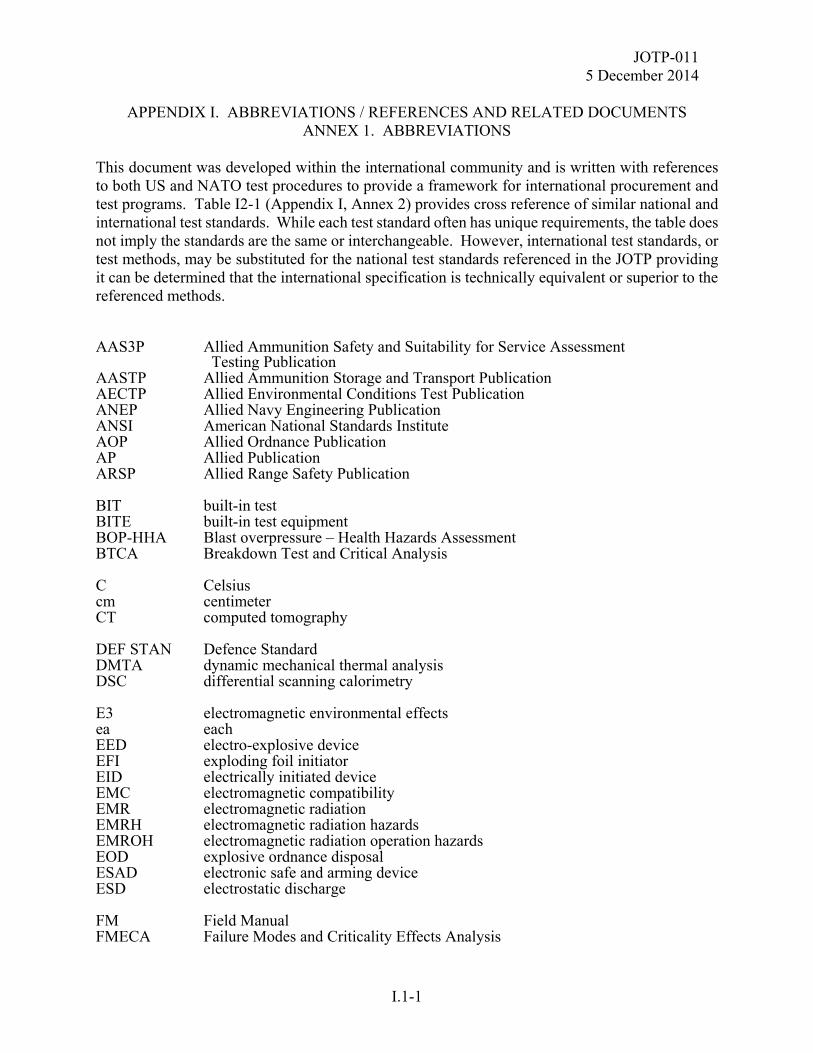
JOTP-011 5 December 2014
APPENDIX I. ABBREVIATIONS / REFERENCES AND RELATED DOCUMENTS
ANNEX 1. ABBREVIATIONS
I.1-1
This document was developed within the international community and is written with references to both US and NATO test procedures to provide a framework for international procurement and test programs. Table I2-1 (Appendix I, Annex 2) provides cross reference of similar national and international test standards. While each test standard often has unique requirements, the table does not imply the standards are the same or interchangeable. However, international test standards, or test methods, may be substituted for the national test standards referenced in the JOTP providing it can be determined that the international specification is technically equivalent or superior to the referenced methods. AAS3P Allied Ammunition Safety and Suitability for Service Assessment Testing Publication AASTP Allied Ammunition Storage and Transport Publication AECTP Allied Environmental Conditions Test Publication ANEP Allied Navy Engineering Publication ANSI American National Standards Institute AOP Allied Ordnance Publication AP Allied Publication ARSP Allied Range Safety Publication BIT built-in test BITE built-in test equipment BOP-HHA Blast overpressure – Health Hazards Assessment BTCA Breakdown Test and Critical Analysis C Celsius cm centimeter CT computed tomography DEF STAN Defence Standard DMTA dynamic mechanical thermal analysis DSC differential scanning calorimetry E3 electromagnetic environmental effects ea each EED electro-explosive device EFI exploding foil initiator EID electrically initiated device EMC electromagnetic compatibility EMR electromagnetic radiation EMRH electromagnetic radiation hazards EMROH electromagnetic radiation operation hazards EOD explosive ordnance disposal ESAD electronic safe and arming device ESD electrostatic discharge FM Field Manual FMECA Failure Modes and Criticality Effects Analysis
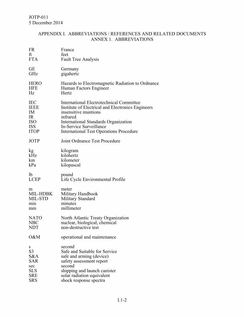
JOTP-011 5 December 2014
APPENDIX I. ABBREVIATIONS / REFERENCES AND RELATED DOCUMENTS
ANNEX 1. ABBREVIATIONS
I.1-2
FR France ft feet FTA Fault Tree Analysis GE Germany GHz gigahertz HERO Hazards to Electromagnetic Radiation to Ordnance HFE Human Factors Engineer Hz Hertz IEC International Electrotechnical Committee IEEE Institute of Electrical and Electronics Engineers IM insensitive muntions IR infrared ISO International Standards Organization ISS In-Service Surveillance ITOP International Test Operations Procedure JOTP Joint Ordnance Test Procedure kg kilogram kHz kilohertz km kilometer kPa kilopascal lb pound LCEP Life Cycle Environmental Profile m meter MIL-HDBK Military Handbook MIL-STD Military Standard min minutes mm millimeter NATO North Atlantic Treaty Organization NBC nuclear, biological, chemical NDT non-destructive test O&M operational and maintenance s second S3 Safe and Suitable for Service S&A safe and arming (device) SAR safety assessment report sec second SLS shipping and launch canister SRE solar radiation equivalent SRS shock response spectra
JOTP-011 5 December 2014
APPENDIX I. ABBREVIATIONS / REFERENCES AND RELATED DOCUMENTS
ANNEX 1. ABBREVIATIONS
I.1-3
SSP system support package STANAG Standardization Agreement TOP Test Operations Procedure UK United Kingdom UN United Nations UNDEX underwater explosion US United States UV ultraviolet vert vertical VERTREP Vertical Replenishment at Sea WLA Whole Life Assessment

JOTP-011 5 December 2014
APPENDIX I. ABBREVIATIONS / REFERENCES AND RELATED DOCUMENTS
ANNEX 1. ABBREVIATIONS
I.1-4
(This page is intentionally blank.)
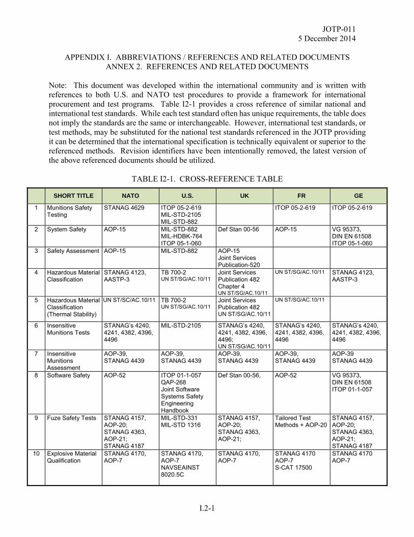
JOTP-011 5 December 2014
APPENDIX I. ABBREVIATIONS / REFERENCES AND RELATED DOCUMENTS
ANNEX 2. REFERENCES AND RELATED DOCUMENTS
I.2-1
Note: This document was developed within the international community and is written with references to both U.S. and NATO test procedures to provide a framework for international procurement and test programs. Table I2-1 provides a cross reference of similar national and international test standards. While each test standard often has unique requirements, the table does not imply the standards are the same or interchangeable. However, international test standards, or test methods, may be substituted for the national test standards referenced in the JOTP providing it can be determined that the international specification is technically equivalent or superior to the referenced methods. Revision identifiers have been intentionally removed, the latest version of the above referenced documents should be utilized.
TABLE I2-1. CROSS-REFERENCE TABLE
SHORT TITLE NATO U.S. UK FR GE
1 Munitions Safety Testing
STANAG 4629 ITOP 05-2-619 MIL-STD-2105 MIL-STD-882
ITOP 05-2-619 ITOP 05-2-619
2 System Safety
AOP-15 MIL-STD-882 MIL-HDBK-764 ITOP 05-1-060
Def Stan 00-56 AOP-15 VG 95373, DIN EN 61508 ITOP 05-1-060
3 Safety Assessment
AOP-15 MIL-STD-882 AOP-15 Joint Services Publication-520
4 Hazardous Material Classification
STANAG 4123, AASTP-3
TB 700-2 UN ST/SG/AC.10/11
Joint Services Publication 482 Chapter 4 UN ST/SG/AC.10/11
UN ST/SG/AC.10/11 STANAG 4123, AASTP-3
5 Hazardous Material Classification (Thermal Stability)
UN ST/SC/AC.10/11 TB 700-2 UN ST/SG/AC.10/11
Joint Services Publication 482 UN ST/SG/AC.10/11
UN ST/SG/AC.10/11
6 Insensitive Munitions Tests
STANAG’s 4240, 4241, 4382, 4396, 4496
MIL-STD-2105
STANAG’s 4240, 4241, 4382, 4396, 4496; UN ST/SG/AC.10/11
STANAG’s 4240, 4241, 4382, 4396, 4496
STANAG’s 4240, 4241, 4382, 4396, 4496
7 Insensitive Munitions Assessment
AOP-39, STANAG 4439
AOP-39, STANAG 4439
AOP-39, STANAG 4439
AOP-39, STANAG 4439
AOP-39 STANAG 4439
8 Software Safety
AOP-52
ITOP 01-1-057 QAP-268 Joint Software Systems Safety Engineering Handbook
Def Stan 00-56,
AOP-52 VG 95373, DIN EN 61508 ITOP 01-1-057
9 Fuze Safety Tests STANAG 4157, AOP-20; STANAG 4363, AOP-21; STANAG 4187
MIL-STD-331 MIL-STD 1316
STANAG 4157, AOP-20; STANAG 4363, AOP-21;
Tailored Test Methods + AOP-20
STANAG 4157, AOP-20; STANAG 4363, AOP-21; STANAG 4187
10 Explosive Material Qualification
STANAG 4170, AOP-7
STANAG 4170, AOP-7 NAVSEAINST 8020.5C
STANAG 4170, AOP-7
STANAG 4170 AOP-7 S-CAT 17500
STANAG 4170 AOP-7
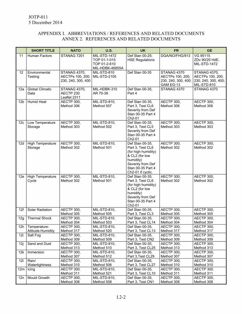
JOTP-011 5 December 2014
APPENDIX I. ABBREVIATIONS / REFERENCES AND RELATED DOCUMENTS
ANNEX 2. REFERENCES AND RELATED DOCUMENTS
I.2-2
SHORT TITLE NATO U.S. UK FR GE
11 Human Factors STANAG 7201 MIL-STD-1472 TOP 01-1-015 TOP 01-2-610 MIL-HDBK-46855A
Def Stan 00-25; HSE Regulations
DGA/NO/FHG/913 VG 95115 ZDv 90/20 HdE, MIL-STD-1472
12 Environmental Testing
STANAG 4370, AECTPs 100, 200, 230, 240, 300, 400
MIL-STD-810 MIL-STD-2105
Def Stan 00-35 STANAG 4370 AECTPs 100, 200, 230, 240, 300, 400; GAM EG-13
STANAG 4370, AECTPs 100, 200, 230, 240, 300, 400;MIL-STD-810
12a Global Climatic Data
STANAG 4370, AECTP 230 Leaflet 2311
MIL-HDBK-310 AR 70-38
Def Stan 00-35, Part 4
STANAG 4370 STANAG 4370
12b Humid Heat AECTP 300, Method 306
MIL-STD-810, Method 507
Def Stan 00-35, Part 3, Test CL6 Severity from Def Stan 00-35 Part 4 Ch2-01
AECTP 300, Method 306
AECTP 300, Method 306
12c Low Temperature Storage
AECTP 300, Method 303
MIL-STD-810, Method 502
Def Stan 00-35, Part 3, Test CL5 Severity from Def Stan 00-35 Part 4 Ch2-01
AECTP 300, Method 303
AECTP 300, Method 303
12d High Temperature Storage
AECTP 300, Method 302
MIL-STD-810, Method 501
Def Stan 00-35, Part 3, Test CL6 (for high humidity) & CL2 (for low humidity) Severity from Def Stan 00-35 Part 4 Ch2-01 if cyclic.
AECTP 300, Method 302
AECTP 300, Method 302
12e High Temperature Cycle
AECTP 300, Method 302
MIL-STD-810, Method 501
Def Stan 00-35, Part 3, Test CL6 (for high humidity) & CL2 (for low humidity) Severity from Def Stan 00-35 Part 4 Ch2-01
AECTP 300, Method 302
AECTP 300, Method 302
12f Solar Radiation AECTP 300, Method 305
MIL-STD-810, Method 505
Def Stan 00-35, Part 3, Test CL3
AECTP 300, Method 305
AECTP 300, Method 305
12g Thermal Shock AECTP 300, Method 304
MIL-STD-810, Method 503
Def Stan 00-35, Part 3, Test CL14
AECTP 300, Method 304
AECTP 300, Method 304
12h Temperature-Altitude-Humidity
AECTP 300, Method 317
MIL-STD-810, Method 520
Def Stan 00-35, Part 3, Test CL13
AECTP 300, Method 317
AECTP 300, Method 317
12i Salt Fog AECTP 300, Method 309
MIL-STD-810, Method 509
Def Stan 00-35, Part 3, Test CN2
AECTP 300, Method 309
AECTP 300, Method 309
12j Sand and Dust AECTP 300, Method 313
MIL-STD-810, Method 510
Def Stan 00-35, Part 3, Test CL25
AECTP 300, Method 313
AECTP 300, Method 313
12k Immersion AECTP 300, Method 307
MIL-STD-810, Method 512
Def Stan 00-35, Part 3,Test CL29
AECTP 300, Method 307
AECTP 300, Method 307
12l Rain/ Watertightness
AECTP 300, Method 310
MIL-STD-810, Method 506
Def Stan 00-35, Part 3, Test CL27
AECTP 300, Method 310
AECTP 300, Method 310
12m Icing AECTP 300. Method 311
MIL-STD-810, Method 521
Def Stan 00-35, Part 3, Test CL10
AECTP 300. Method 311
AECTP 300. Method 311
12n Mould Growth AECTP 300, Method 308
MIL-STD-810, Method 508
Def Stan 00-35, Part 3, Test CN1
AECTP 300, Method 308
AECTP 300, Method 308
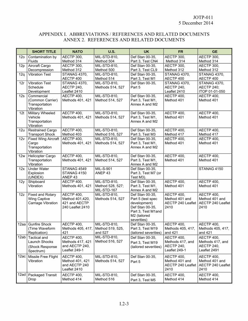
JOTP-011 5 December 2014
APPENDIX I. ABBREVIATIONS / REFERENCES AND RELATED DOCUMENTS
ANNEX 2. REFERENCES AND RELATED DOCUMENTS
I.2-3
SHORT TITLE NATO U.S. UK FR GE
12o Contamination by Fluids
AECTP 300, Method 314
MIL-STD-810, Method 504
Def Stan 00-35, Part 3, Test CN4
AECTP 300, Method 314
AECTP 300, Method 314
12p Aircraft Cargo Decompression
AECTP 300, Method 312
MIL-STD-810, Method 500
Def Stan 00-35, Part 3, Test CL9
AECTP 300, Method 312
AECTP 300, Method 312
12q Vibration Test STANAG 4370, AECTP 400
MIL-STD-810, Method 514
Def Stan 00-35, Part 3, Test M1
STANAG 4370, AECTP 400
STANAG 4370, AECTP 400
12r Vibration Test Schedule Development
STANAG 4370, AECTP 240, Leaflet 2410
MIL-STD-810, Methods 514, 527
Def Stan 00-35, Part 5
STANAG 4370, AECTP 240, Leaflet 2410
STANAG 4370, AECTP 240; ITOP 01-01-050
12s Commercial (Common Carrier) Transportation Vibration
AECTP 400, Methods 401, 421
MIL-STD-810, Method 514, 527
Def Stan 00-35, Part 3, Test M1, Annex A and M2
AECTP 400, Method 401
AECTP 400, Method 401
12t Military Wheeled Vehicle Transportation Vibration
AECTP 400, Methods 401, 421
MIL-STD-810, Methods 514, 527
Def Stan 00-35, Part 3, Test M1, Annex A and M2
AECTP 400, Method 401
AECTP 400, Method 401
12u Restrained Cargo Transport Shock
AECTP 400, Method 403
MIL-STD-810, Method 516, 527
Def Stan 00-35, Part 3, Test M3
AECTP 400, Method 417
AECTP 400, Method 417
12v Fixed Wing Aircraft Cargo Transportation Vibration
AECTP 400, Methods 401, 421
MIL-STD-810, Methods 514, 527
Def Stan 00-35, Part 3, Test M1, Annex A and M2
AECTP 400, Method 401
AECTP 400, Method 401
12w Helicopter Cargo Transportation Vibration
AECTP 400, Methods 401, 421
MIL-STD-810, Method 514, 527
Def Stan 00-35, Part 3, Test M1, Annex A and M2
AECTP 400, Method 401
AECTP 400, Method 401
12x Under Water Explosion (UNDEX)
STANAG 4549 STANAG 4150 ANEP 43
MIL-S-901 ANEP 43
Def Stan 00-35, Part 3, Test M7 (or Test M3).
STANAG 4150
12y Shipboard Vibration
AECTP 400, Methods 401, 421
MIL-STD-810, Method 528, 527; MIL-STD-167
Def Stan 00-35, Part 3, Test M1, Annex A and M2
AECTP 400, Method 401
AECTP 400, Method 401
12z Fixed and Rotary Wing Captive Carriage Vibration
AECTP 400, Method 401,420, 421 and AECTP 240 Leaflet 2410
MIL-STD-810, Methods 514, 527
Def Stan 00-35, Part 5 (test spec development) Def Stan 00-35, Part 3, Test M1and M2 (tailored severities)
AECTP 400, Method 401 and AECTP 240 Leaflet 2410
AECTP 400, Method 401 and AECTP 240 Leaflet 2410
12aa Gunfire Shock (Time Waveform Replication)
AECTP 400, Methods 405, 417, 421
MIL-STD-810, Method 519, 525, and 527
Def Stan 00-35, Part 3, Test M19 (tailored severities)
AECTP 400, Methods 405, 417, and 421
AECTP 400, Methods 405, 417, and 421
12ab Tactical and Launch Shocks (Shock Response Spectrum)
AECTP 400, Methods 417, 421 and AECTP 240, Leaflet 249-1
MIL-STD-810, Method 516, 527
Def Stan 00-35, Part 3, Test M19 (tailored severities)
AECTP 400, Methods 417, and AECTP 240, Leaflet 249-1
AECTP 400, Methods 417, and AECTP 240, Leaflet 2491
12ac Missile Free Flight Vibration
AECTP 400, Method 401, 421 and AECTP 240 Leaflet 2410
MIL-STD-810, Methods 514, 527
Def Stan 00-35, Part 5
AECTP 400, Method 401 and AECTP 240 Leaflet 2410
AECTP 400, Method 401 and AECTP 240 Leaflet 2410
12ad Packaged Transit Drop
AECTP 400, Method 414
MIL-STD-810, Method 516
Def Stan 00-35, Part 3, Test M5
AECTP 400, Method 414
AECTP 400, Method 414
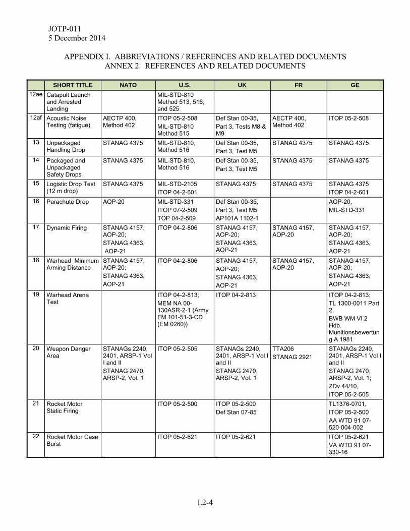
JOTP-011 5 December 2014
APPENDIX I. ABBREVIATIONS / REFERENCES AND RELATED DOCUMENTS
ANNEX 2. REFERENCES AND RELATED DOCUMENTS
I.2-4
SHORT TITLE NATO U.S. UK FR GE
12ae Catapult Launch and Arrested Landing
MIL-STD-810 Method 513, 516, and 525
12af Acoustic Noise Testing (fatigue)
AECTP 400, Method 402
ITOP 05-2-508 MIL-STD-810 Method 515
Def Stan 00-35, Part 3, Tests M8 & M9
AECTP 400, Method 402
ITOP 05-2-508
13 Unpackaged Handling Drop
STANAG 4375 MIL-STD-810, Method 516
Def Stan 00-35, Part 3, Test M5
STANAG 4375 STANAG 4375
14 Packaged and Unpackaged Safety Drops
STANAG 4375 MIL-STD-810, Method 516
Def Stan 00-35, Part 3, Test M5
STANAG 4375 STANAG 4375
15 Logistic Drop Test (12 m drop)
STANAG 4375 MIL-STD-2105 ITOP 04-2-601
STANAG 4375 STANAG 4375 STANAG 4375 ITOP 04-2-601
16 Parachute Drop AOP-20 MIL-STD-331 ITOP 07-2-509 TOP 04-2-509
Def Stan 00-35, Part 3, Test M5 AP101A 1102-1
AOP-20, MIL-STD-331
17 Dynamic Firing STANAG 4157, AOP-20; STANAG 4363, AOP-21
ITOP 04-2-806 STANAG 4157, AOP-20; STANAG 4363, AOP-21
STANAG 4157, AOP-20
STANAG 4157, AOP-20; STANAG 4363, AOP-21
18 Warhead Minimum Arming Distance
STANAG 4157, AOP-20; STANAG 4363, AOP-21
ITOP 04-2-806 STANAG 4157, AOP-20; STANAG 4363, AOP-21
STANAG 4157, AOP-20
STANAG 4157, AOP-20; STANAG 4363, AOP-21
19 Warhead Arena Test
ITOP 04-2-813; MEM NA 00-130ASR-2-1 (Army FM 101-51-3-CD (EM 0260))
ITOP 04-2-813 ITOP 04-2-813; TL 1300-0011 Part 2, BWB WM VI 2 Hdb. Munitionsbewertung A 1981
20 Weapon Danger Area
STANAGs 2240, 2401, ARSP-1 Vol I and II STANAG 2470, ARSP-2, Vol. 1
ITOP 05-2-505
STANAGs 2240, 2401, ARSP-1 Vol I and II STANAG 2470, ARSP-2, Vol. 1
TTA206 STANAG 2921
STANAGs 2240, 2401, ARSP-1 Vol I and II STANAG 2470, ARSP-2, Vol. 1; ZDv 44/10, ITOP 05-2-505
21 Rocket Motor Static Firing
ITOP 05-2-500 ITOP 05-2-500 Def Stan 07-85
TL1376-0701, ITOP 05-2-500 AA WTD 91 07-520-004-002
22 Rocket Motor Case Burst
ITOP 05-2-621 ITOP 05-2-621 ITOP 05-2-621 VA WTD 91 07-330-16
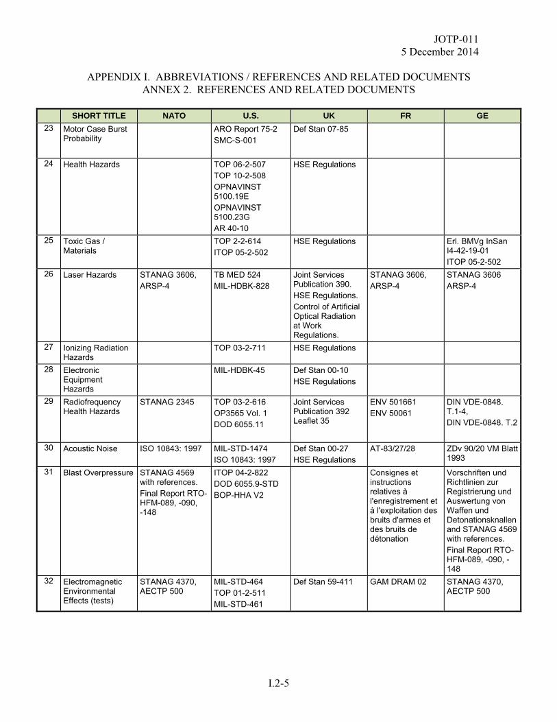
JOTP-011 5 December 2014
APPENDIX I. ABBREVIATIONS / REFERENCES AND RELATED DOCUMENTS
ANNEX 2. REFERENCES AND RELATED DOCUMENTS
I.2-5
SHORT TITLE NATO U.S. UK FR GE
23 Motor Case Burst Probability
ARO Report 75-2 SMC-S-001
Def Stan 07-85
24 Health Hazards TOP 06-2-507 TOP 10-2-508 OPNAVINST 5100.19E OPNAVINST 5100.23G AR 40-10
HSE Regulations
25 Toxic Gas / Materials
TOP 2-2-614 ITOP 05-2-502
HSE Regulations Erl. BMVg InSan I4-42-19-01 ITOP 05-2-502
26 Laser Hazards STANAG 3606, ARSP-4
TB MED 524 MIL-HDBK-828
Joint Services Publication 390. HSE Regulations. Control of Artificial Optical Radiation at Work Regulations.
STANAG 3606, ARSP-4
STANAG 3606 ARSP-4
27 Ionizing Radiation Hazards
TOP 03-2-711 HSE Regulations
28 Electronic Equipment Hazards
MIL-HDBK-45 Def Stan 00-10 HSE Regulations
29 Radiofrequency Health Hazards
STANAG 2345 TOP 03-2-616 OP3565 Vol. 1 DOD 6055.11
Joint Services Publication 392 Leaflet 35
ENV 501661 ENV 50061
DIN VDE-0848. T.1-4, DIN VDE-0848. T.2
30 Acoustic Noise ISO 10843: 1997 MIL-STD-1474 ISO 10843: 1997
Def Stan 00-27 HSE Regulations
AT-83/27/28 ZDv 90/20 VM Blatt 1993
31 Blast Overpressure STANAG 4569 with references. Final Report RTO-HFM-089, -090, -148
ITOP 04-2-822 DOD 6055.9-STD BOP-HHA V2
Consignes et instructions relatives à l'enregistrement et à l'exploitation des bruits d'armes et des bruits de détonation
Vorschriften und Richtlinien zur Registrierung und Auswertung von Waffen und Detonationsknallen and STANAG 4569 with references. Final Report RTO-HFM-089, -090, -148
32 Electromagnetic Environmental Effects (tests)
STANAG 4370, AECTP 500
MIL-STD-464 TOP 01-2-511 MIL-STD-461
Def Stan 59-411
GAM DRAM 02
STANAG 4370, AECTP 500
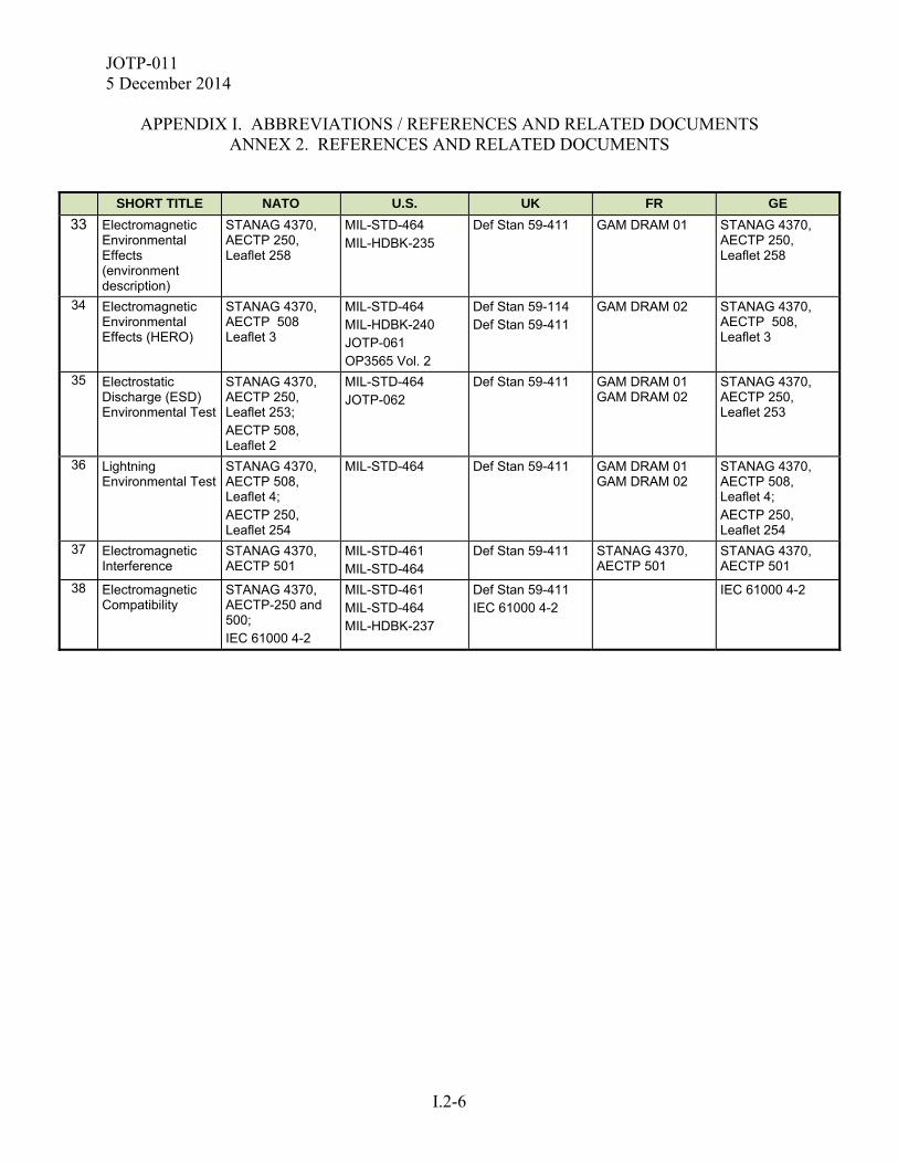
JOTP-011 5 December 2014
APPENDIX I. ABBREVIATIONS / REFERENCES AND RELATED DOCUMENTS
ANNEX 2. REFERENCES AND RELATED DOCUMENTS
I.2-6
SHORT TITLE NATO U.S. UK FR GE
33 Electromagnetic Environmental Effects (environment description)
STANAG 4370, AECTP 250, Leaflet 258
MIL-STD-464 MIL-HDBK-235
Def Stan 59-411
GAM DRAM 01 STANAG 4370, AECTP 250, Leaflet 258
34 Electromagnetic Environmental Effects (HERO)
STANAG 4370, AECTP 508 Leaflet 3
MIL-STD-464 MIL-HDBK-240 JOTP-061 OP3565 Vol. 2
Def Stan 59-114 Def Stan 59-411
GAM DRAM 02
STANAG 4370, AECTP 508, Leaflet 3
35 Electrostatic Discharge (ESD) Environmental Test
STANAG 4370, AECTP 250, Leaflet 253; AECTP 508, Leaflet 2
MIL-STD-464 JOTP-062
Def Stan 59-411
GAM DRAM 01 GAM DRAM 02
STANAG 4370, AECTP 250, Leaflet 253
36 Lightning Environmental Test
STANAG 4370, AECTP 508, Leaflet 4; AECTP 250, Leaflet 254
MIL-STD-464
Def Stan 59-411
GAM DRAM 01 GAM DRAM 02
STANAG 4370, AECTP 508, Leaflet 4; AECTP 250, Leaflet 254
37 Electromagnetic Interference
STANAG 4370, AECTP 501
MIL-STD-461 MIL-STD-464
Def Stan 59-411 STANAG 4370, AECTP 501
STANAG 4370, AECTP 501
38 Electromagnetic Compatibility
STANAG 4370, AECTP-250 and 500; IEC 61000 4-2
MIL-STD-461 MIL-STD-464 MIL-HDBK-237
Def Stan 59-411 IEC 61000 4-2
IEC 61000 4-2
JOTP-011 5 December 2014
Comments, suggestions, or questions on this document should be addressed to Range Infrastructure Division (CSTE-TM), U..S Army Test and Evaluation Command, 2202 Aberdeen Boulevard, Aberdeen Proving Ground, Maryland 21005-5001; or e-mailed to:
Since contact information can change, you may want to verify the currency of this address information using the ASSIST Online database at https://assist.dla.mil. This document is identified by the accession number (AD No.) printed on the first page.