REPORT DOCUMENTATION PAGE CALIN · report documentation page er calin.fm 4. title ... v2. s. army...
20
SECURITY CLASSIFICATION of THIS PAGE (Whnrat ., Fnt-r-d) REPORT DOCUMENTATION PAGE ER CALIN.FM 4. TITLE (snd ShfI)5 T-YPEOF REPORT & PE'fDCOEE V2. S. ARMY TEST Aýi) EVALUATION COMMAND DEVKLOPMEIT L74~ TEFST 1T (PP) - C0101ON TELSi OPER-ATIONS PROCEDURE'S Final \ _____ I 'BALLIMTC. ;jESTTNG OF PE1RSONNIEL ARMOR MA.4T ERIALS"ý 6 44IAF IORMING JRr. FIFPORT NUM6'EN AU T OR(. a CONTRACT OR GRANT NUMBER(.) '4 ~ ~ PEFORINGORANIZATIuN NAME AND ADDRESS IJ RGA LMNPOET ' -. AREA & WORK UNIT NtiJMRERS U. S. ARMY; ABRDIEEN; PROVING GROUND (STEAP-MT-M) :L)I/ -- _-_ ABERDEEN PROVING; GROUND , MA-RYLANI) 21.005 AMC(R-310-6 T"C 7jNTRTOL.LN OFICE NAME AND ADDRESS L". S * ARMY TEST AND) EVALUATION COMMfANI) (AMSTE-ME), NJ 6 Januavy 1975k ABERD)EEN PROVING GROUND, MARYLAND 21005 111a. .W&Z6aER OF PAGES ,E 6, Mr-NITORING AGENCY NAME & ADORESS~i/f dilfferet fromt Conefolling Office) . 1UITY CLASS. of Ib . rport) K ECLLASSIFI A. ION' DOWN 0 RA N6 SCHEDULE 6. DIST'HIBUTION STATEMENT (.1 hi.e Raportj Approved for publi c rel ease; distr ibuLiuji UuuLLiiitEd1. 17 DIST RI13UTION STATEMENT i~ h htcte-,ted In Block 20, It differ-r, from Repo0rt) 18. SýUPPLEMENTARY NOTES 19. KEY WORDS (Continue o- revrs. aide It nece..a.y and Idantity by block number) Armor Ba]l-istics Body Armor Personal. Equipment 20 A ý RACT (Confinu* an rovers& side if necessary srd~ Identity by block number) 7e)scribes methods for evaluating the resistance of personnel armor material. to perforation by attacking projectile fragments, simulated fragments, and small arms arninunition.,vvovers physical characteristicu of -materials, firing tests for ballistic limits of materials, determination of residual velocities, and environmental conditioning. D~ot applicable to material in actual armor configuration. J. DD I JJ OAK'3 147 3 EDITION OF I NOV 65 IS OBSOLETE UNCLASSIFIED SECUJRITY CLASSIFICATION OF Ttt!S PAGE (When, 0.15 FoIredj
-
Upload
truongngoc -
Category
Documents
-
view
224 -
download
0
Transcript of REPORT DOCUMENTATION PAGE CALIN · report documentation page er calin.fm 4. title ... v2. s. army...
SECURITY CLASSIFICATION of THIS PAGE (Whnrat ., Fnt-r-d)
REPORT DOCUMENTATION PAGE ER CALIN.FM
4. TITLE (snd ShfI)5 T-YPEOF REPORT & PE'fDCOEE
V2. S. ARMY TEST Aýi) EVALUATION COMMAND DEVKLOPMEIT L74~TEFST 1T (PP) - C0101ON TELSi OPER-ATIONS PROCEDURE'S Final \ _____
I 'BALLIMTC. ;jESTTNG OF PE1RSONNIEL ARMOR MA.4T ERIALS"ý 6 44IAF IORMING JRr. FIFPORT NUM6'EN
A U T OR(. a CONTRACT OR GRANT NUMBER(.)
'4 ~ ~ PEFORINGORANIZATIuN NAME AND ADDRESS IJ RGA LMNPOET
' -. AREA & WORK UNIT NtiJMRERSU. S. ARMY; ABRDIEEN; PROVING GROUND (STEAP-MT-M) :L)I/ -- _-_ABERDEEN PROVING; GROUND , MA-RYLANI) 21.005 AMC(R-310-6
T"C 7jNTRTOL.LN OFICE NAME AND ADDRESS
L". S * ARMY TEST AND) EVALUATION COMMfANI) (AMSTE-ME), NJ 6 Januavy 1975k
ABERD)EEN PROVING GROUND, MARYLAND 21005 111a. .W&Z6aER OF PAGES
,E 6, Mr-NITORING AGENCY NAME & ADORESS~i/f dilfferet fromt Conefolling Office) . 1UITY CLASS. of Ib .rport)
K ECLLASSIFI A. ION' DOWN 0 RA N6SCHEDULE
6. DIST'HIBUTION STATEMENT (.1 hi.e Raportj
Approved for publi c rel ease; distr ibuLiuji UuuLLiiitEd1.
17 DIST RI13UTION STATEMENT i~ h htcte-,ted In Block 20, It differ-r, from Repo0rt)
18. SýUPPLEMENTARY NOTES
19. KEY WORDS (Continue o- revrs. aide It nece..a.y and Idantity by block number)
ArmorBa]l-isticsBody ArmorPersonal. Equipment
20 A ý RACT (Confinu* an rovers& side if necessary srd~ Identity by block number)
7e)scribes methods for evaluating the resistance of personnel armor material.to perforation by attacking projectile fragments, simulated fragments, andsmall arms arninunition.,vvovers physical characteristicu of -materials,firing tests for ballistic limits of materials, determination of residual
velocities, and environmental conditioning. D~ot applicable to material inactual armor configuration. J.
DD I JJ OAK'3 147 3 EDITION OF I NOV 65 IS OBSOLETE UNCLASSIFIED
SECUJRITY CLASSIFICATION OF Ttt!S PAGE (When, 0.15 FoIredj

I
/

U, S. AR4MY TEST AND EVALUATION COMMANDDEVELOPMENT TEST II (EP) - COMMON TEST OPERATIONS PROCEDURES
AMSTE-RP-702-109*Test Operations Pr:ocedure I0-'-506 6 January 1975
BALLISTIC TESTING OF PERSONNEL ARMOR MATERIALS
Paragraph page
Section I. GENERALPurpose and Scope ..... ............ 1 .Background ..... ............ ... 2 1Equipment and Facilities ..... ....... 3 2
II. TEST PROCEDURESPreliminary Activities ........ 4 2Determining Residual Velocities: The
VS-VR Curve. . .. ......... 5 3Determining V50 Bnllistic Limit Witi
Simulated Fragments ........... ... 6 12Determining V50 Ballistic Limit With
Gun-Fired Fragments ........... ... 7 16Determining V50 Ballistic Limit With
Small Arms Projectiles . . . . . .. 8 16
Environmental Conditioning . . . . .. 9 16
APPENDIX. REFERENCES ................... ................... .18
SECTION IGENERAL
1, Purpose and Scope. This TOP describes methods of evaluating the re-sistance of the material used in personnel armor to penetration by pro-jectile fragments, simulated fragments, and small arms ammunition.
2. Background. Personnel armor is designed to pr,)tect the wearer againstinjury from small fragments generated by exploding munitions and, whenspecified, from small arms fire. It may be made from a variety ofmaterials including metals, textiles, plastics, and ceramics. Personnelarmor inclides items such as helmets, armor vests, face shields, torsoshield, leg armor, and protective suits. It is relatively light inweight, usually between 1/4 and 4 pounds per square foot, but may beheavier if it is to provide protection against small arms fire.
*This TOP supersedes MTP 10-2-506, 4 October 1968.
Approved for public release, distribution unlinm-ted.

TOP 10-2-506 6 January 1975
Materials are submitted as flat sections to facilitate testing, butthey may be furnished as helmets, armor vests, etc., \when required forspecific tests. These materials are given laboratory tests for hardness,strength, elongation, and other physical characteristics. To determineballistic protection, they must be subjected to resistance-to-penetra-tion tests with appropriate missiles.
Some teats, particularly ballistic acceptance tests, are conductedto determine the ability of material to prevent perforation (i.e.,complete penetration) by the attacking projectile or fragment. Suchtests are covered by paragraphs 6, 7, and 8. Other tests are conductednot only to determine the ability of material to prevent perforations,but also to determinE the velocity that remains when an attacking frag-ment does perforate the armor. This test, which provides lethality datathat can be equated to bodily injury, is covered in paragraph 5.
3. Equipment and Facilities. Equipment and facilities are describedunder the individual test proceaures below.
SYCT[ON TI
TEST PROCEDURES
4. Preliminary Activities.
4.1 Pretest Data Review. The test engineer should study the resultsof past firings of similar tests in order to make an estimate of theballistic properties of the test item and to detect any gross errors inthe testing techniques.
4.2 Physical Characteristics of Test Materials. The following informa-tion is obtained and recorded for each armor item to be tested:
a. Manufacturer.
b. Weight (nearest 0.01 ounce per square foot).
c. Average thickness of area fired upon (nearest 0.001 inch).
d. Full der.:ýiption of each layer if material is composite armor.
e. Bourdlng technique (when applicable).
4.3 Laboratory Properties of Test Materials. The following propertiesof test materials are obtained either from the manufacturer's laboratorydat!. or from tests made in-house (TOP's 3-2-806, 3-2-807 and 1-2-504).
sa Metals - Commercial designation, hardness, tensile strength,yield strength, elongation, impact toughness, alloy type, composition.
2

6 January 1975 TOP 10-2-506
b. Plastics - Commarceil type, configuration, hardness, brittleness,elongation, water absorption.
c. Textiles , Commercial type, fiber size, type and density ofweave, strength, water absorption.
d. Ceramics - Commercial type, brittleness.
e. Composites and laminates - Properties of individual layers.
5. Determining Residual Velocities: The Vs-Vg Curve.
5.1 Objective. To obtain quantitative measures of the ability of bodyarmor materials to completely stop or reduce the velocity (thereforelethality) of attacking fragments of various velocities. To accomplishthis, fragments are fired from weapons over a range of velocities, andthe residual velocity (fragment velocity remaining after a completepenetration of the armor) of each is measured. The results are presentedgraphically as a VS-VR (striking velocity versus residual velocity)curve,.
5.2 Method. A detailed treatment of this method is given in reference5 (appendix).
5.2 Fragments. The fragments used in this test are actual shell frag-ments recovered from static detonations of HE projectiles, especiallymortar shall and foreign ammunition. A soft recovery technique, generallyusing wallboard which will not damage the fragments, ,iust be used. TOP/HTP 4-2-813 describes a method for recovering a small portion of themain upray. To recover all of the main spray would require wallb.ard tobe stacked all around the sides of the projectile at an appropriatestandoff. Each recovered fragment is weighed, and those of 2, 4, 8, 16,20, 24, 40, and 64 grains are grouped. In any group, weight tolerances
of;kl 2 to 3) paLcLn t arc preferred but: should not exrsed (+) 5 percent.Each fragment to be fired is geometrically characterized by measuringthe presented area in 16 different orientations (i.e., the 16 nonopposingfaces of an icosahedron, which is a polyhedron formed with 20 equilateraltriangles). The 16 areas are averaged to form A which is an importantfactor in connection with air drag and retardation by armor materials,The parameter K, the average shape factor of the fragment, is defined as
K- m
where m is the mass of the fragment, The fragment to be fired is mountedin a sabot as described below.
5.2.2 Velocity MeTuhement Techniquest. 'Me two methods employed tomeasure•ragment velocities are (a7) th flash X-ray method (figs. I and2) which should be used when the target may break up, such as during the
3
iMP' 10-2-03)' o January 1975
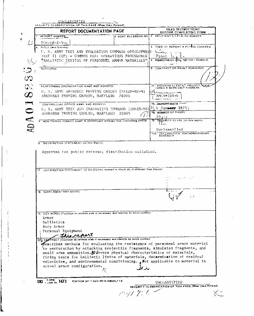
tet t•,g eol me a si c or ha rd-faiced compos ites; and (b ) the chronograph,break-screen (or lumiltie screen) method (figs. 3 and 4) which is generallvuSel when nilimMHtlli' or f.abric-type tarpets are to he tested_ The brealksrteens shown in I flgore I are used to trigger the X-ray tubes and chrono-
,raph. Flashl \-ray (radiographiic) techniques in general are covered inFl'l/M.,) 4-2-82'_ wit•h .;peciftc information on velocity measurements in
FI0 2-2-71H. Chro•o•graphir techniques are described in TOP/AiTP 4-2-805.Velocity measuiremeets of fragments requiret that special drag coefficientsb. ohbtaianed fromn a pproprlate sources. Gun-to-tarrget distnnces will vary.l'iev may 1,e as I lot , as 53 inches (fig. 1 ) for very small fragiments
i irl a, h'.., armor-; for the larger fragments greater distances are used.
5.2. 1 Fa;i, .ities. In addition to velocity measuring equinment, the0] 1 ]ow'i i; I ac it i.E le. art- r*.quiredt:
"a. Smooth botre we,-p, "nThe caliber is determined by the sizeannI A'I iit of ,hhe n! Cl-,Ient and veloci.ty range to he explored. A calibert ,-4ý), smooth-horc-, Mann barrel is suitable for launchting fragments of
2 t 701 grain.
b. Sabot. 'line sabot material is usually a type of plastic (1inen-base phenolic, lexan, etc.), with the design, diameter, and length deter-mined bv the weight and shape of the projectile fragment. The fragmentis hold in positinn on the sabot wit-h paste or a nouhiardenilng adLtesive.
Reference 4d (appendix) describes firing with a sabot, A teflon pusheris placed behind the sabot to act as an obturator.
c. Sabot stripper or tipping device, The standard stripperscrewed to the gun muzzle or the NRL (Naval Research Lab) tipper deviceis necessary to separate the fragment from the sabot. (See also ref. 4b,appendix.) A sabot-discarding aid is also used. This is a steel deflec-tor plate, 1/4-inch minimum thickness, with a 1- to 1-1/4-inch diameterhole aligned with the center of the gun bore, located between the gunmuzzle andi the first bre;ak screen.
d. Velocity break screen. A 4- by 6-1/4-inch (minimum) manifoldpaper with silver circuit grid, line space and width determined by frag-ment size, is located both in front of and behind the target to initiatevelocity measuring instrumentation.
e. Yaw cards. These consist of double weight, color print photo-gcaphic paper located within 1 inch in front of the target. They showthe presented area of fragments at impact.
f. Witness material. Gypsum wallboard, 1/2-inch thick, is usedto catch residual fragments, which are recovered for analytical purposes.
4

Li January 1975 TOP 10-2-506
Witness3! ShLUets
X-Ray Tube
• •.Fi 1.11
•- j-Target
•2• •-Yaw Card
S / Break /xeen #2
Bra Breakn Scen1t
/Deflector Plate
A AA
* A =Representative, disranee from X-ray Itubes to film surfacrs 68.0 inches.
Gun Note: All dimensions in. inclhes.
Figure 1. Schematic Diagram Showing Flash X-Ray Units Set Up toMeasure Striking and Residual Velocities in Test of Body Armor with 2-to 70-Grain Fragments.•
Ng
N5
I I I I I I I I -Yaw Card I II I I

Six
Figure 2.* Interior of Je~sting C:1Ihamber Showinug Four Pairs of X,"-Ray
Tube V 3, X n 1) Aligned With Pathl of- Fragment Through lDe-fi~ector Plate (P) , Target (T) , and Witness Material] (1).
6

o January 1975 TOP 1(-"-5ý)6
- I Break Scruee /
cc -Break Screen "
"il(I ! -- 'F . \Býlreai ScrAee f74
0reak Screen S
~-CO Bre.ak Screen ~
TAiGi : AT 45ý
Break Screena ;13
/ / Breaik Screen
I
Break Screen
(1-0.
ccýNotes All dimensions in iaches.
ruti
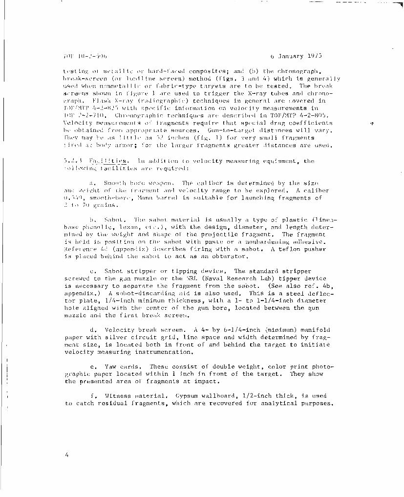
Figure 3. Break Screen Arrangement for M~easuring Striking andResidual Velocities in Tests of Body Armor at 0' and 45' ObliquitiesWith Fragments Under 70 Grains.
7

I
JAILIVV 3,) 7')1*
C
4)
C 4-'
'� ',-�
U 4-',ITJ �t
U
wW4-�
4Z
In
4-)C)
'-4 �� U
U)
J2c.�(Jo)
� cCI-
wo
oC
U -
H
8
u January 1975 TOP 1i0-2-506
5,2.4 Firinlroceku(re. lbis procedure Is generally in conformance withreference 5 (adpend i.x)
"rhe i irst step is to acqulire dat a or estimating the "li. mit ingvelocity" ýVL) -. The VL is the same as the V-O ball stir, limit ; that is,the highest strikinig velocity at which the probabil ity ol a completepenetritrion is zero. At the VT,, the residual velocity (VR) wi] I be zerosince the fragment will, Just get through the target with no remainingvelocity. As the fragment velocity is increased, pe.rTforations will beginto occur and residual vtlocities will increase.
The VL is estimated graphically. One method that has been used
is as follows: From previous wetk an estimate is milade of the velocity5()() fps above the VL- A -ornpellaiat ciarpo is chiesen that will produc:e
this velocity fcr the fragment to be fired. The VR of this round andof all other compilete penetration rounds is recorded. If a completepenetration occurs, the velocity for subsequent rounds is reduced byapproximately 200-fps intervals until a partial penetration occurs. Ifa partial penetration octcurs on the second rouni fired, tihe velocity isincreased in 2601-fps intervals on the next two rounds. If a partialpenetration occurs on the thLrui round, the velocity is increased by 200fps on the next round. In an; event, three complete penetrations areitquired-, and, if necessary. additional rounds at 200-fps higher veloci-ties are fired to obtain them. An initial esti.mate of Cite VL can bemade after three or four complete penetrations have been obtained, pro-vided that one shows very little residual velocity or a partial penetra-tion was also obtained.
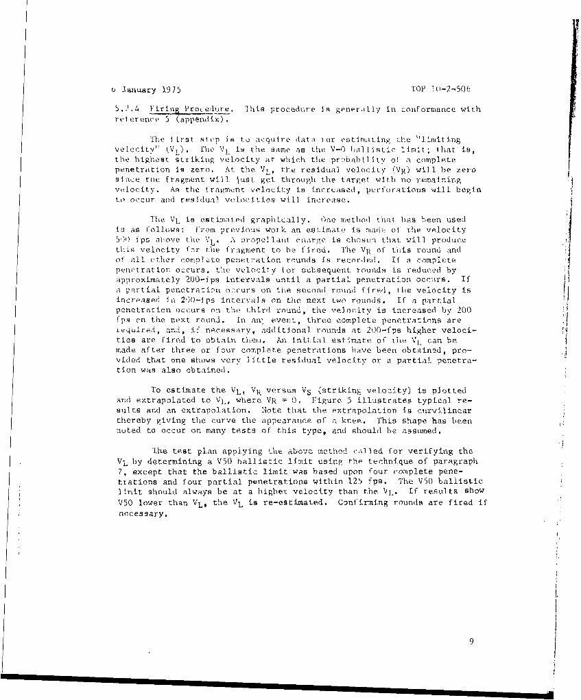
To estimate the VL, VR versus VS (striking velocity) is plottedand extrapolated to Vj., where VR = 0. Figure 5 illustrates typical re-sults and an extrarolation. Note that the extrapolation is curvilinearthereby giving the curve the appearance of a knee. This shape has beennoted to occur on many tests of this type, and should he assumed.
The test plan applying LhCe above methodl e,-iled for verifying theVL by determining a V50 ballistic limit using the technique of paragraph7, except that the ballistic limit was based upon four complete pene-trations and four partial penetrations within 125 fps. The V50 ballisticlimit should always be at a higher velocity than the VL. If results show
V50 lower than VL. the VL is re-estimated. Confirming rounds are fired ifnecessary.
9

'1W'B 12-5 January 19J5
VL Ftii a'k of the il:Iiliv;4
o 900' 7
- on 7T IT 7+4 '1411fi- i. .t I
500 1(000 1500 2000 2 500 3000
Striking Velocity V5s (Ifps)
Figure 5. Estimate of' Lirittinv \'eluc'itv.
1 0 devel op a co~up] t-Lt' V? vtt au Vs curve, rati os of VSc: Vi, ran~ging;from 1.00 to 4.00 (in the above 0.350e) are set lip to determine whichstriking velocitijes slmul.1 be usedc. The fol Inwing is :i suitable selectionof 9triking velocities.
ApproximateStrikingVel1ocity,
I .00 \7I1.0t) Vii . 2 viý1.19 \TL1.. 2 V1ý1.34 V1ý1.42 VLl- -0 8 VL2.25 yEý3.0)0 VL4. 00 VL
Earlier firing willI have been close eno;ugh to some of these valuesto be acceptable, and need not be repeated. Figure 6 shows tlhe resultsof a complete firing program. If firing is to be limited, firings inthe range of 1.0 to 1.5 VL should be given prcfert-nce.
101

u January 1'9715 '101' 10-2-5)0
- - - 1-i
A4 I Ipoint-S VL = 152() p Ip1200 - - ,- --- H..- ---- ,A I; : I . I i- -i -[ .. I !, ; .: - - --
12 -f.. . F
I - Z .1
0ti,,- ,
10 1
-,77-
.300 I I~**~
0 8()I6~)2400 3200 4000
1,ra men t: St riking Ve IocitY, f'P:
Figure 0. Reprf.scnt;itive Vs-VR Curve for a Speciific Fragment Mass-
Target: Material Combination Showing Faulty Curva Generatied by Insuffir-ient
Data as Contrasted to True Curvo.
5.2.) Iata Reguired. TJhe data tor he obtained from tests of this type
are specified by the sponsoring agency and general Iv include, but are
not limited to, the following:
a. Protection ballistirc limit of target-fragment combination.
b. Striking vel(mity ol fragm.,nL.
c. Fragment presented area just before target impact.
d. Residual velocity of major fragment or fragments.
e. Limiting velocity of each fragment-target combination.
11.
TOP 10-2-506 6 January 1975
f. Target thLicknuss, areal density, etc.
g. Fragment weight, length, width, thickness, and avc-ape shapetAL-tor prior to firing.
6. Determining V50 Ballistic Limit with Simulated Fragments.
6.1 Objective. To evaluate the resistance of personnel armor materialsto attack from hardened steel configurations that are designed tosimulate fragments,
6.1.1 Advantages. This test method has the following advantages overother fragment tests:
a. Missiles of consisteat weight, shape, and properties are used,
permitting consistency of test conditions.
b. Missiles can be mass produced and are relatively cheap.
c. Precise velocity control is easily achieved.
d. Small targets and modest range facilities are possible.
6.1.2 Disadvantages. In the opinion of many investigators, the fragmentsimulators do not simulate fragments adequately. While they can screenmaterials, fragment simulators cannot show what the performance of atarget will be against actual fragments launched by projectile detona-tions.
6.2 Methcd.
6.2.1 Types of Simulated Frag•ments. There are basically two types ofsimulated fragments.
a. A standard fragment-simulating (FS) projectile that is awidely used, specific type of solid steel projectile available in diffe-rent weights.
b, Various other geometric shapes most of which require sabotsfor launching.
Standard FS projectiles (fig. 7) are homologous in shape; producedin sizes of cal .22 (17 grains), cal .30 (44 grains), cal .50 (207 grains),and 20-mm (830 grains); and procured under MIL-P-46593A(ORD). The FSprojectile is an attempt to produce fragments that are standardized anddo not require a sabot for firing. It was expressly developed for
evaluating the fragment resistance of development body armor and light-weight aircraft and vehicle armor. FS projectiles are also employed inthe acceptance testing of body armor, Cubes, suitable for mounting in
12

h January 1975 TOP 10-2-506
sabots, h-ve also been standardized and are procurable under MIL-P-46125(>{R). Cylinders, parallelepipeds, darts, and spheres have also beenused. Some of these are shown in TOP 2-2-722.
%tKav lw-~l
• . ;* 'N' /11't, 1 ] t '
N, <~ ~' B re!ak
" ~ ~ ~ ~ A Vv1 i l rtcIItl lL~iL 'i u dL'iL,-,r i I • .,-ril
S~~~~LI,11-: to, fLlin uur'areul -- t !I-) •ll'
Figure 7. F°ragment-Simulating Projectiles Used to EvaluatePersonnel, Armor,
6.2.2 Characteristics _of Impacts byf Frag4ment Simulators, The orientationof the fragment simulator upon impact with armor has a considerable effectupon the efficiency of penetration and is a factor in the scatter of
data. A cube, I-or example, hitting on a corner will penetrate moreeasily than if it hits on one of its f].at sides. This is riot a problemwith FS pr'ojectiles when fired at a 0° obliquity target, but does becomea factor with oblique targets because penetration is less efficient ifthe projectile strikes on a tapered portion of its nose rather than onan untapered portion. Right circular cylinders do not have this dis-advantage at obliquities while retaining the advantage of not requiringsabots. A major disadvantage of cylinders is the sparsity of data con-cerning them for use in comparisons with materials tested in the past.
in I'tI'IFlI
Spheresof coure, provdrperf cittconisc tencyi of impac orintaion
Fu hig ure 7. Fotragoment-Simulating Pojteie Usred tossEvaluarte
6.2. fragme cts. s so mat b rgetSmltos h retto
of te fagmet smultor ponimpct wth rmo hasa cnsierabe efec

TOP 10-2-506 6 January 1975
The vast majority of tests with fragment simulators employ thestandard FS projectile for several reasons: there is a large amount ofpast data available involving them; they are readily available inseveral weights, relatively inexpensive to fire, and they reasonablysimulste fragments. Thus, much body armor testing is performed with FSproje-ctiles,
6.2.3 Typea of Tests. The type of test conducted is dependent upon theresources (funds and target area) available, the objective of the testprogram, and the specification, if applicable.
a. The traditional test program invol.ves obtaining a 10-round,V50 protection ballistic limit using the up-and-down firing technique('TOP 2-2-710). The ballistic limit is, then, the average of 10 strikingvelocities: the five highest partial penetrations and the five lowestcomplete penetrations occurring within a velocity spread of 125 fps. Ifa ballistic limit is not reached within a spread of 125 fps, a 14-shotballistic limit with a spread of 150 fps is acceptable.
b. A second testing method follows the Langlie sampling technique(TOP 2-2-710) whic' generally involves 12 to 16 firings, produces astandard deviatioi ,s well as a V50 ballistic limit, and is suiLable for
comparing types c iaterials. This is the minimum test that should beused for comparing materials.
c, A third method, and one that is more desirable for comparingdevelopment materials than either of the above, is to obtain three V50,10-round ballistic limits for each target.
d. Occasionally, a fourth method is employed when there is aneed to obtain a vqry precise measurement of the ballistic limit and itsstandard deviation, In this case, the Probit method (see TOP 2-2-710)is preferred, with perhaps 50 to 200 frag-.ent silluators fired, composedof groups of 8 to 15 fired at each of 6 to 15 velocities that cover therange from V-0 to V-lO0.
In firin;, a gun-to-target distance of 16 feet is consideredstandard for body armor, with two lumiline screens spaced about 3 feetapart for velocity measurements. (Special tests may have shorter dis-tances as illustrated in para 5.) A complete penetration is definedby the "protection" criterion; that is, an impact that results in eithera portion of the plate or fragment moving behind the plate with sufficientenergy to perforate a witness sheet of 0.020-inch aluminum 2024-T3 or T4placed about 6 inhes behind the armor. Fragment velocities are con-trolled as usual by varying the weight of propellant. In doing so,however, the varying weights of the combined weight of sabot plus frag-ment must be considered. When applicable, a ygw card is placed Just infront of the target to indicate impact orientations. If residualvelocities are required, they are obtained as specified in paragraph 5.
34

6 January 1975 TOP 10-2-506
6.3 Data Required, All data pertinent to the armor material are recordedas indicated in paragraph 4. The exact obliquity cf the armor and thestriking velocity of each partial and complete penetration are recorded.(As required by tie directive, residual velocity of the fragment afterit passes through the armor, and velocity, size, and distribution of thefragments displaced from the target may be recorded as in para 5.2.)Impact orientations are described when pertinent.
6,4 Analytical Plan. The analysis technique depends upon the method oftesting employed and the criterion statement. In most cases the objectiveis to determine which of two or more materials provides the highest resis-tance to penetration. If two or more V50 ballistic limits have been ob-tained on each target under similar conditions, it is often appropriateto test the hypothesis that the mean ballistic limits of two or morematerials are equal. Assuming that the ballistic limit is a normallydistributed random variable, the test hypothesis becomes q simple 'ft"
test. If the hypothesis is rejected, it is concluded that there is asignificant difference in the ballistic limits of the two materials. Ifmore than two materials are to be compared, analysis of variance techni-ques can be used to test the hypothesis.
The probability of penetration as a function of striking velocityis assumed to be described by the cumulative normal distribution, themean of which is identical to the V50 ballistic limit. The Langlie testmethod and the up-and-down method provide a way of estimating the mean(p) and standard deviation (o ) as well as their standard errors aUAand c.
2 5P n
(At Aberdeen Proving Ground a computer program, based upon the method ofmaximum likelihood, is available to make these determinations - ref. 4c,
appendix.) If a is known from earlier data, O0j can be computed directly.
When Cr is not known, a method of obtaining an unbiased estimate of its
value is provided in the computer program. To test the hypothesis that
the ballistic limits of two materials are equal, the following test
statistic is defined:A -A
V 2 2A. +; 0 ^AP1 P2
Since A is approximately normally distributed with a mean of zero and astandard deviation of one, standard techniques for testing hypothesesfor normally distributed random variables can be used.
15
"101' 10-2--500 6 January 1975
If the Probbit method (at ]east 50 rounds) is used, the V50 ballisticlimit and standard devLItLion are determined either by the use of reference/k or by plotting (lit i on a curve and pic-king ol V the desired measuresof performance.
7. Determining V5() Balli-st ic Limit with Gun-Fired Fragments. Fragmentsto he fired are selected to be as close to the prescribed weight aspossible, preferably wilhin (+)2 to 3 percent, but not beyond (±)5 per-cent. The rangfe of fragment weights that must realistically be toleratedwithin a given weighi category is a factor that tends to promote a largezone of mixed resultts during the determination of a V50 ballistic limit(see TOP 2-2-710). An even more significant factor in this regard is thatthe wide variety of shapes, hardness patterns, and impact orientationsthat are possible with randomly selected fragments within the same weightcategory will result in great variations in the penetrating efficiency ofthe different fragments. Thus, within the constraints of a typical testprogram, the V50 ballistic limit determination can, at best, only be con-sidered a fair approximat.on. The wide variations in the attacking missilecause a considerable amount of data scatter. (This is the primary reasonthat the methodology of paragraph 6 is often preferred over shootingactual fragments.)
Velocity measurements aie made with lumiline screens or break screensas described in paragraph 5.2.1, except that measurement of residualvelocities behind the target is not required. The facilities requiredare the same as those in paragraph 5.2.2.
T o determine the V50 ballistic limits, the up-and-down firing techni-qule is usually employed (TOP 2-2-710) as described in paragraph 6.2.3.While it is preferable to average 10 rounds, fewer rounds may be used ifthe test program is limited (see TOP 2-2-710).
8. Determining V50 Ballistic Limit with Small Arms Projectiles. Occasion-ally there is a requirement to evaluate the resistance to penetration ofbody armor by small arms projectiles fired at relatively low velocities.The same up-and-oown firing technique described in 6.2.3 above and inTOP 2-2-710 is used.
9. Environmental Conditioning. The properties of some body armor mater-ials are affected by various climatic conditions, particularly high andlow temperatures and high humidity. Thus, in addition to tests of bodyarmor under standard ambient conditions (59' to 950 F, 15' to 35' C),there may be a requirement t.o test body armor under certain severe con-ditions. The extreme conditions usually are specified; if not, storagetemperatures will conform to those of AR 70-38 followed by balisrbctesting at somewhat more moderate temperatures that take into accountthe moderating effect of the human body for which the armor is designed.A humidity exposure, when required, is performed in accordance with TO]'/MH' 4-2-820, and the ballistic test conducted while the material is still

6 January 1975 TOP 10-2-506
exposed. Conditions of exposure related to the ballistic test will beconsistent with those for basic tests of body armor (TOP/MTP 10-2-206).
Recommended changes to this puiblication should be forwarded toCommander, U. S. Army Test and Evaluation Command, ATTN:AMSTE-KE, Aberdeen Proving Ground, Md. 21005. Technical infor-mation may te obtained from the preparing activity: Commander,U. S. Army Aberdeen Proving Ground, ATTN: STEAP-MT-M, AberdeenProving Ground, Md. 21005. Additional copies are available fromthe Defense Documentation Center, Cameron Station, Alexandria,Va. 22314. This document is identified by the accession number(AD No.) printed on the first page.
17

6 January 1975 TOP 10-2-506
APPENDIX
REFERENCES
1. MIL-P-46125 (MR), "Projectile Cubes, Fragment-Simulating," 21September 1967.
2. MIL-P-46593A (ORD), "Projectile, Calibers .22, .30, .50 and 20-rmmFragment-Simulating," and Amendment 1, 12 October 1964.
3. MIL-STD-662B, "Ballistic Acceptance Test Method for Personnel ArmorMaterial," 23 July 1971.
4. Aberdeen Proving Ground Reports:
a. Demaree, C. L., "Research Test of Steel Armor Attacked by Frag-ment-Simulating Cubes to Provide Data for Lethality Studies (U),"DPS-1098 (Confidential), October 1963.
b. Feroli, John A. and Van Caneghem, R. J., "Final Report on SpecialStudy of Methodology for Determining Protection Against ShellFragments," APG-MT-4363, 1974. (TECOM Project 9-CO-011-000-051.)
c. Hagan, J., "Computer Program for Analysis of Sensitivity DataFollowing a Normal Distribution," Analytical Laboratory Report62-AL-154, 24 August 1962.
d. Loveless, L. G., "Comparative Fragmentation Test of American andSoviet Artillery Projectiles," Analytical Laboratory Report63-AL-191, 31 December 1963.
5. DeLuca, Eugene; Frost, Robert A.; and Prifti, Joseph J.; "TerminalBallistic Simulation of Munition Fragments," Army Materials and14achanic. Research Center. Watertown. Mass., September 1974.
18