REPORT - sintef.no · and the hydraulic hoses interfered with the oil and the ice and it was...
44
www.sintef.no SINTEF Materials and Chemistry Marine Environmental Technology Oil in Ice - JIP REPORT
Transcript of REPORT - sintef.no · and the hydraulic hoses interfered with the oil and the ice and it was...
www.sintef.no
SINTEF Materials and ChemistryMarine Environmental Technology
Oil in Ice - JIP
REPORT

Funding Partners
R&D Partners
Cooperating Partners
Preface SINTEF has in cooperation with SL Ross Environmental Research Ltd and DF Dickins Associates LLC on behalf of the oil companies AGIP KCO, Chevron, ConocoPhillips, Shell, Statoil and Total initiated an extensive R&D program; Joint industry program on oil spill contingency for Arctic and ice covered waters. This program was a 3-year program initiated in September 2006 and finalized in December 2009.
The objectives of the program were; • To improve our ability to protect the Arctic environment against oil spills. • To provide improved basis for oil spill related decision-making: • To advance the state-of-the-art in Arctic oil spill response.
The program consisted of the following projects: • P 1: Fate and Behaviour of Oil Spills in Ice • P 2: In Situ Burning of Oil Spills in Ice • P 3: Mechanical Recovery of Oil Spills in Ice • P 4: Use of Dispersants on Oil Spills in Ice • P 5: Remote Sensing of Oil Spills in Ice • P 6: Oil Spill Response Guide • P 7: Program Administration • P 8: Field Experiments, Large-Scale Field Experiments in the Barents Sea • P 9: Oil Distribution and Bioavailability
The program has received additional financial support from the Norwegian Research Council related to technology development (ending December 2010) and financial in kind support from a number of cooperating partners that are presented below. This report presents results from one of the activities under this program. Stein Erik Sørstrøm Program Coordinator ([email protected])


2
TABLE OF CONTENTS
Executive summary .......................................................................................................................3
1 Introduction ............................................................................................................................6
2 Objectives ................................................................................................................................6
3 Experimental Background Information...............................................................................7 3.1 Skimmers for testing.......................................................................................................7 3.2 Vessel and working boats .............................................................................................10 3.3 Testing set up ................................................................................................................10 3.4 Testing scenario ............................................................................................................11 3.5 Auxiliary equipment .....................................................................................................12 3.6 Documentation and laboratory analyses .......................................................................12
4 Time log.................................................................................................................................13
5 Results....................................................................................................................................14 5.1 Testing of the Helix 1000 Skimmer..............................................................................14
5.1.1 Flow of emulsion to the skimmer .....................................................................15 5.1.2 Ice processing....................................................................................................16 5.1.3 Separation of oil, water and ice.........................................................................16 5.1.4 Icing / freezing of equipment. ...........................................................................16 5.1.5 Importance of oil type .......................................................................................16 5.1.6 Conclusions and recommendations...................................................................17
5.2 Testing of the LRB 150 Skimmer.................................................................................19 5.2.1 Flow of emulsion to the skimmer .....................................................................20 5.2.2 Ice processing....................................................................................................20 5.2.3 Separation of oil, water and ice.........................................................................21 5.2.4 Icing / freezing of equipment. ...........................................................................21 5.2.5 Conclusions and recommendations...................................................................21
5.3 Testing of the SeaMop 4090 Skimmer .........................................................................22 5.3.1 Flow of emulsion to the skimmer .....................................................................23 5.3.2 Ice processing....................................................................................................23 5.3.3 Separation of oil, water and ice.........................................................................23 5.3.4 Icing / freezing of equipment. ...........................................................................23 5.3.5 Conclusions and recommendations...................................................................23
6 Conclusions and lessons learned .........................................................................................24 6.1 Final conclusions from the skimmer testing .................................................................24 6.2 Lessons learned.............................................................................................................26
7 Acknowledgement ................................................................................................................27
8 References .............................................................................................................................27
Appendix A: Helix Skimmer test 21. May 2008. ......................................................................28
Appendix B: LRB Skimmer tests 23. May 2008. ......................................................................31
Appendix C: SeaMop and Helix skimmer tests 23. May 2008. ...............................................35
3
Executive summary The work reported herein was part of an experimental field trial in the Barents Sea from 18. to 30. May 2008. The field trial was performed in the eastern part of the Barents Sea east of the island of Hopen. The research vessel M/V Lance was used as a base of operations with an MOB boat and one smaller work boat as supplementary work platforms.
Totally three oil recovery skimmers were tested during this field trial over a period of two days. The three skimmers are manufactured by Lamor Corporation AB of Finland (LRB 150 Skimmer) and Ro-Clean Desmi AS of Denmark (Helix 1000 Skimmer and SeaMop 4090 Skimmer).
Based on the testing performed during the field experiment in 2008 and previous testing performed in the SINTEF ice basin in March to June 2007, the following overall conclusions have been drawn:
Ro-Clean Desmi Helix 1000 Skimmer: The results from testing of the Helix 1000 Skimmer both in the ice basin and in the field indicate that it can be effective in collecting oil under the conditions found during the testing. Cohesive oil slicks can be effectively drawn into the brushes provided that the drum speed is not too high (5 – 10 rpm in these tests). The skimmer works best in low ice concentrations (up to 40 – 50 %) and might also have a potential for application alongside larger ice floes. This is a small skimmer and large recovery rates should not be expected, even in low ice concentrations. However, the principle of this skimmer, with rotating brush drums, seems to work quite well in ice. During the field experiments the Helix Skimmer proved to be a good tool when cleaning inside the boom of remaining oil after the experiments. Due to the size of the skimmer and its helical shape, it was possible to remove small amounts of emulsion from the “corners” of the boomed area.
The manufacturer of this skimmer is presently building a larger version of this skimmer with a hexagonical shape rather than the helical shape of the Helix Skimmer. The new skimmer will also contain improvements like “winterisation”, floating elements, umbilical for hoses etc. However, the Helix Skimmer can still be a versatile device for smaller oil spills in ice-covered waters.
Lamor LRB 150 Skimmer:
It can be concluded that the LRB Skimmer represents state-of-the-art technology for the recovery of oil spills in an ice field. By using the original intended excavator crane and an experienced operator, this skimmer is expected to have the potential to effectively recover oil in ice up to ice covers of 60 – 70 %. The crane onboard Lance was not optimal for skimmer testing and for the LRB skimmer the angle of the skimmer could not be changed during testing. The discharge hose and the hydraulic hoses interfered with the oil and the ice and it was difficult to hold the skimmer in an optimal position. In the commercial complete LRB Skimmer package, the hoses are incorporated in the hydraulic arm that deploys and manoeuvres the skimmer.
Due to the flow created under the drum brush, the skimmer exhibited good ice processing capabilities with low uptake of free water. A short test with cleaning off oiled ice surfaces revealed the skimmer to also be capable of this task. The LRB Skimmer has to be operated by a crane in the immediate vicinity of a vessel. Under certain conditions, this can be a drawback as a vessel tends to open up the ice field and hence spreading of the oil to thinner oil thicknesses.
Ro-Clean Desmi SeaMop 4090 Skimmer: Rope mop skimmers have been tested on several occasions in the past, also in ice and under cold conditions. It has been concluded that the concept has a high potential for recovering oil in ice (Johannessen et al., 1996). The concept has also been adapted to more local and specific conditions, for example to collect oil in trenches in the ice by moving the rope mop horizontally in the trench. The very limited test performed during the field experiment demonstrated the ability of
4
the rope mops to coat with the emulsion used during this testing and lift it to the wringer mechanism.
Rope mop skimmers are oleophilic devices that depend on the oil adhering to the mops. Past experiments, also at SINTEF (Singsaas et al., 2000), have shown that their effectiveness is dependent on the oil type and properties of the emulsion being recovered. At the same time, cohesion is also important. These are attractive forces acting within the oil/emulsion, and because the oil/emulsion has to be lifted several metres cohesion is important to avoid dripping of oil on the way up to the wringing mechanism. In this test, there was only a limited amount of emulsion dripping off the rope mop on the way up to the skimmer unit.
Often when using a rope mop skimmer from a vessel side, the height from the sea surface and up to the skimmer unit can be several metres (typically +/- 6 m). This results in a large surface of the rope mops being exposed to air at any time. In low temperatures and strong winds, this can result in freezing of free water in the rope mops. Most rope mop skimmers are exposed to freezing under such extreme conditions when suspended in the air. Past reports have included recommendations to “winterise” these skimmers. The SeaMop 4090 is equipped with a small manifold that can supply hot water spray to heat the mops as they exit the machine as well as adding water to the oil being collected to promote transfer by the pump. In addition, a tarpaulin can be used to cover the sump of the skimmer and contribute to decreasing the possibility for freezing of rollers, wringers and the pump.
Relevance of oil type and ice regime An IF-30 water in oil emulsion with approximately 50 % water was used both in the basin testing and in the field testing. When it comes to adhesion of oil to the brushes and cohesion forces within the emulsion, the IF-30 is probably close to optimal testing oil for these skimmers. However, for logistic and economic reasons it has not been within the scope of this project to do testing with different oil types. Even if ice processing seems to be the main challenge recovering oil in ice, the oil type and weathering degree still has a significant impact on the recovery effectiveness of different skimmer types.
The target ice cover in these experiments was 30 – 50 % broken ice pieces and floes in addition to the slush ice scenario used in the basin testing. The actual ice regime will have a major impact on the skimmer recovery effectiveness. When referring to 50 % broken ice conditions in this study we mean ice floes of a size up to approximately 1 – 1.5 meter in diameter. Under real conditions in the Arctic 50 % ice coverage normally means that half the sea surface in a given area is covered with ice floes with a diameter of several meter and up to several hundreds of meters. Existing skimmers can only process ice floes/pieces up to only a couple of meters in diameter and needs to circumnavigate larger ice floes. To investigate a skimmer’s ability to process ice and to recover oil within the ice, the chosen ice regimes for testing seem appropriate. However, in a scenario with 50 % ice coverage and with large ice floes present a skimmer can operate in fairly large ice free areas between the ice floes which resemble open waters conditions, most likely with less wave action. Given for instance a blow out under these conditions traditional skimmers can probably work well with high recovery rates in fairly high oil thicknesses with the ice acting as a natural confinement. Reduced recovery rates will then be experienced if the oil thickness is low due to large spreading of the oil or there are smaller ice floes/pieces or slush ice between the larger ice floes restricting the flow of oil to the skimmer.
Lessons learned: One of the objectives of the 2008 field experiment was to gain experience in field work prior to the larger 2009 experiment. The following summarises some of the lessons learned from the 2008 field experiment:
5
• K/V Lance is a good vessel for field work in ice-covered waters. The only shortcoming
related to the skimmer testing was the crane. The skimmers tested are all dependent on a crane that can be operated so that the skimmer is in the right vertical position in the water and can also be moved laterally within the ice field. All skimmers would have been operated more effectively if a different crane has been used. This aspect should be closely examined prior to future field work with any skimmer requiring a deployment arm. Apart from that, Lance functioned well as a base of operations for these experiments and the crew onboard the vessel was very helpful and contributed significantly to the successful outcome of the whole experiment.
• When using the same technique of collecting ice in the future, boats equipped with tow post or bollard should be applied. A pivot point is needed some distance from the engine to allow manoeuvrability when towing boom from a smaller vessel.
• Floating rope should be used for towing to avoid the rope getting caught in the jet drive or propeller of the working boats used.
• The Norlense 35F boom used a double set of loops and rope as a connector. This was time-consuming to use at water level. An ASTM, Universal, Navy or other slide or simple mechanism should be used in the future for connecting section ends. This is especially important when the boom is in the water and contaminated with oil.
• Paravanes, tow floats or bridles attached to connectors would improve and speed up towing when collecting ice.
• Representatives from the manufacturers must be highly competent and knowledgeable persons who are capable of troubleshooting and making repairs and modifications that might be required in the field. Representatives from: Lamor, Ro-Clean Desmi and Norlense, participated during the 2008 field trial and worked well together providing key input to the testing.
6
1 Introduction Most mechanical methods for recovering spilled oil are based on technologies developed for open water conditions. They often have serious limitations in ice-covered waters and recovery capabilities can be highly variable depending on a variety of local environmental conditions and logistics constraints. Some of the main challenges of operating skimmers in ice versus open waters are:
• Limited/difficult access to the oil – deflection of oil together with ice
• Limited flow of slicks to the oil recovery mechanism
• Separation of oil from ice and water
• Pressure in the ice field – structural and strength considerations of the skimmer
• Increased oil viscosity due to low temperatures
• Icing/freezing of oil removal and transfer components in cold climates
• Detection / surveillance of the oil slick, potentially over a long time
• Moving ice of variable size as well as residual currents
It is expected that the largest potential for improving mechanical oil recovery in Arctic and ice-covered waters will be to further improve and adapt existing skimming technologies. Taking into account the remoteness of many of the Arctic areas in question, it is important that equipment for combating oil in ice also can be used in open waters.
In this project, oil spill response equipment manufacturers known to produce equipment with an expected potential for the recovery of oil in ice, were asked to “nominate” existing skimmers for testing in the SINTEF ice basin. The manufacturers were asked to prepare a short description of the “nominated” equipment for communication with the project Reference Group (RG) and decision by the Steering Committee (SC). Approximately 15 manufacturers were invited and six of them responded to the request. After discussions in the RG, a total of six skimmers from four manufacturers were selected for testing in the ice basin. One of the skimmers was equipped with a centrifugal pump unable to pump the viscous emulsion used in the testing. Testing finally involved a total of five skimmers from three different manufacturers in the ice basin (Singsaas et al., 2008A,B,C). Based on the results from the ice basin, testing two existing skimmers, the Helix 1000 and LRB 150 skimmers, were found to have the largest potential for the recovery of oil in broken ice or in a combination of smaller ice pieces and slush ice. It was decided that these two skimmers should be further tested and validated during the experimental field trial in May 2008.
This report focuses mainly on the field experiment conducted in May 2008, but it also compares the results from the ice basin testing with the results from the field experiment for the two skimmers.
2 Objectives The main objective of this project was to document the capability and potential of commercially available skimmers for recovering oil in ice. Based on this documentation, suggestions should be possible for defining and improving the operational spill response window in ice and cold conditions. The testing should also lead to a better understanding of the potential use of these skimmers in ice-covered waters.
The aim with the field experiments was to test and verify the capability of two skimmers previously tested in the SINTEF ice basin and found to have the best potential in Arctic areas. The
7
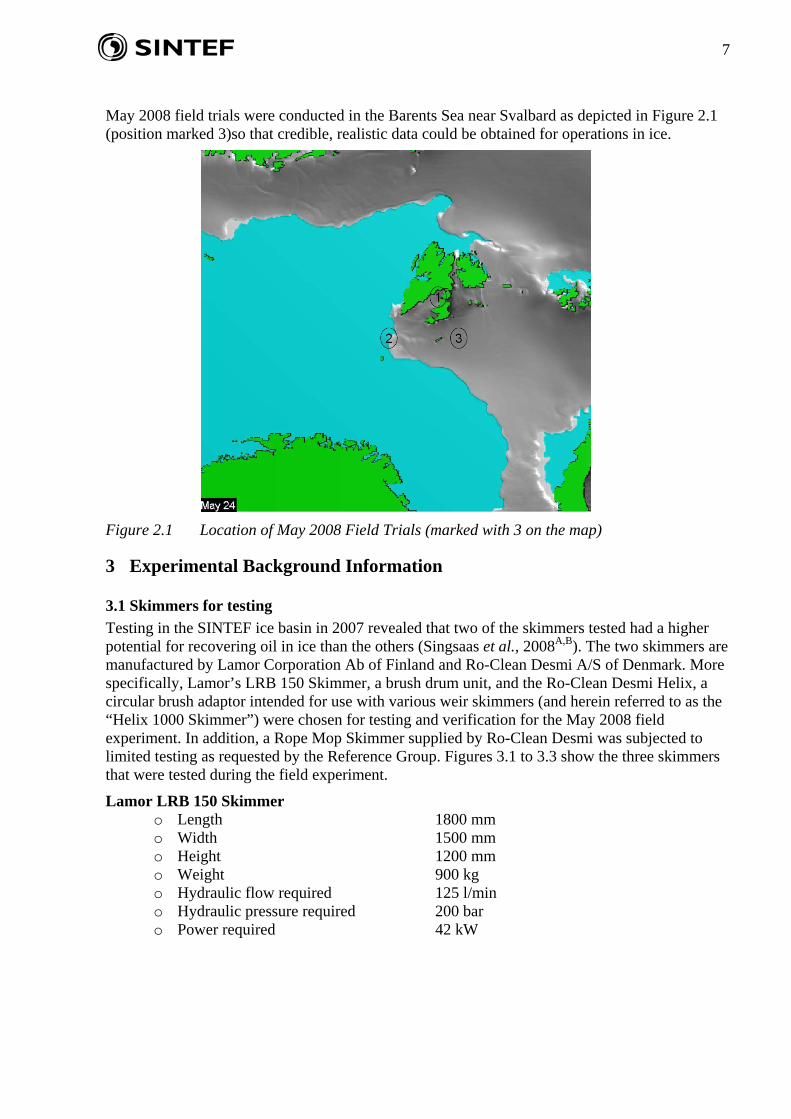
May 2008 field trials were conducted in the Barents Sea near Svalbard as depicted in Figure 2.1 (position marked 3)so that credible, realistic data could be obtained for operations in ice.
Figure 2.1 Location of May 2008 Field Trials (marked with 3 on the map)
3 Experimental Background Information
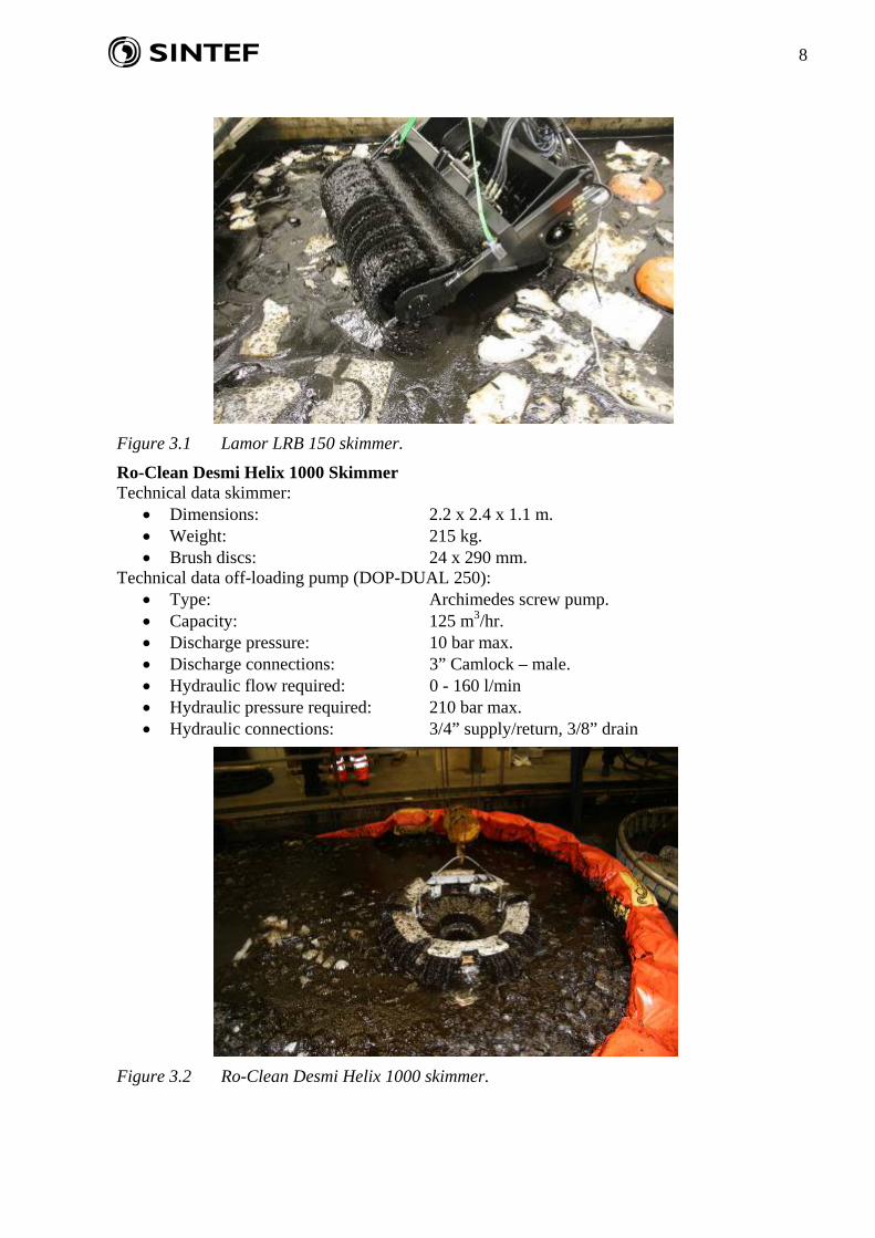
3.1 Skimmers for testing Testing in the SINTEF ice basin in 2007 revealed that two of the skimmers tested had a higher potential for recovering oil in ice than the others (Singsaas et al., 2008A,B). The two skimmers are manufactured by Lamor Corporation Ab of Finland and Ro-Clean Desmi A/S of Denmark. More specifically, Lamor’s LRB 150 Skimmer, a brush drum unit, and the Ro-Clean Desmi Helix, a circular brush adaptor intended for use with various weir skimmers (and herein referred to as the “Helix 1000 Skimmer”) were chosen for testing and verification for the May 2008 field experiment. In addition, a Rope Mop Skimmer supplied by Ro-Clean Desmi was subjected to limited testing as requested by the Reference Group. Figures 3.1 to 3.3 show the three skimmers that were tested during the field experiment.
Lamor LRB 150 Skimmer o Length 1800 mm o Width 1500 mm o Height 1200 mm o Weight 900 kg o Hydraulic flow required 125 l/min o Hydraulic pressure required 200 bar o Power required 42 kW
8
Figure 3.1 Lamor LRB 150 skimmer.
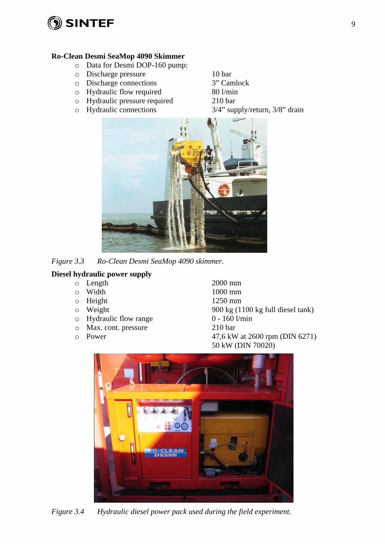
Ro-Clean Desmi Helix 1000 Skimmer Technical data skimmer:
• Dimensions: 2.2 x 2.4 x 1.1 m. • Weight: 215 kg. • Brush discs: 24 x 290 mm.
Technical data off-loading pump (DOP-DUAL 250): • Type: Archimedes screw pump. • Capacity: 125 m3/hr. • Discharge pressure: 10 bar max. • Discharge connections: 3” Camlock – male. • Hydraulic flow required: 0 - 160 l/min • Hydraulic pressure required: 210 bar max. • Hydraulic connections: 3/4” supply/return, 3/8” drain
Figure 3.2 Ro-Clean Desmi Helix 1000 skimmer.
9
Ro-Clean Desmi SeaMop 4090 Skimmer
o Data for Desmi DOP-160 pump: o Discharge pressure 10 bar o Discharge connections 3” Camlock o Hydraulic flow required 80 l/min o Hydraulic pressure required 210 bar o Hydraulic connections 3/4” supply/return, 3/8” drain
Figure 3.3 Ro-Clean Desmi SeaMop 4090 skimmer.
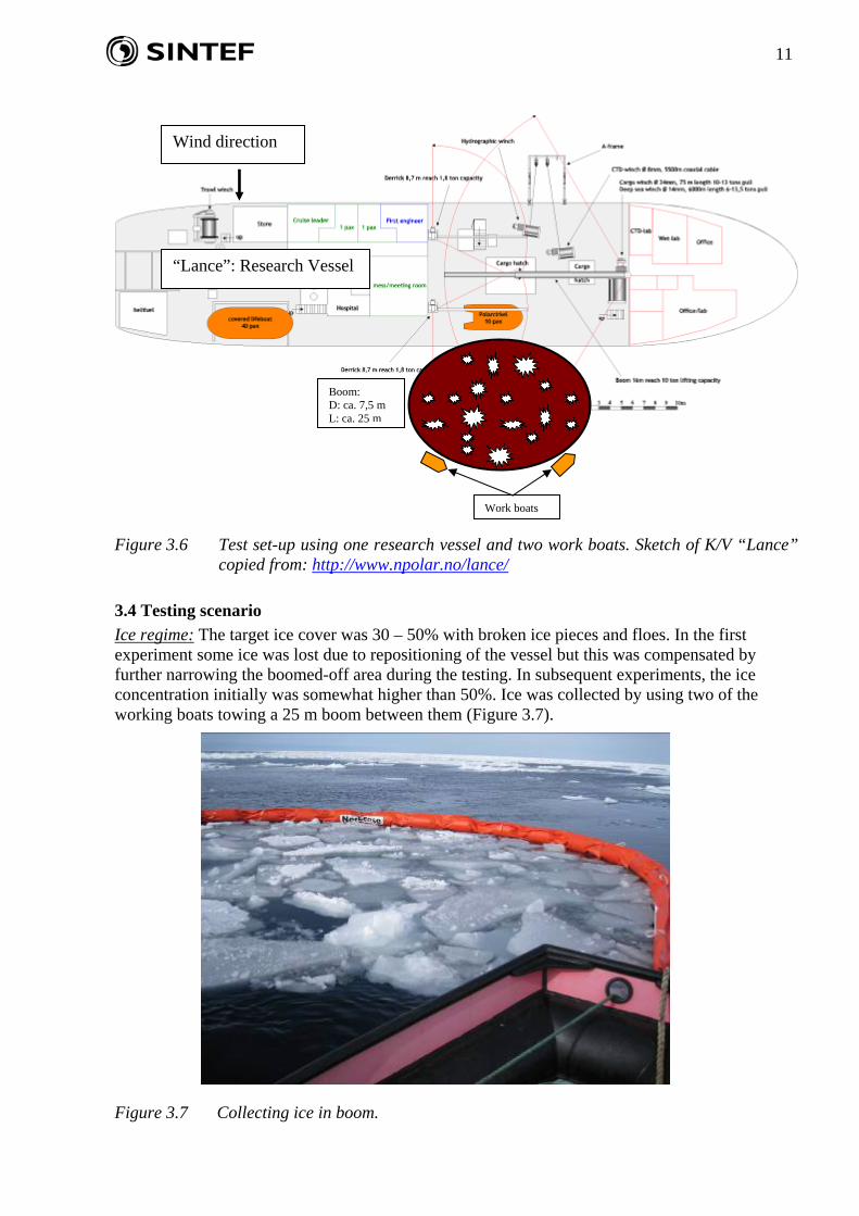
Diesel hydraulic power supply o Length 2000 mm o Width 1000 mm o Height 1250 mm o Weight 900 kg (1100 kg full diesel tank) o Hydraulic flow range 0 - 160 l/min o Max. cont. pressure 210 bar o Power 47,6 kW at 2600 rpm (DIN 6271)
50 kW (DIN 70020)
Figure 3.4 Hydraulic diesel power pack used during the field experiment.

10
3.2 Vessel and working boats The main vessel used was K/V “Lance” owned by the Norwegian Polar Institute (Figure 3.5). The vessel had three working boats and a helicopter onboard. The vessel was equipped with a large crane for skimmer operations and one smaller crane, utilised for other deployment duties, on each side of the vessel. It proved difficult to keep the skimmers in the optimal operating position with the large crane. The vessel has one bow and one stern thruster, which proved very helpful in keeping the vessel in position and in avoiding disturbances from drifting ice floes.
Figure 3.5 K/V “Lance”, the main vessel used during the field experiment.
3.3 Testing set up In order to have maximum control of the emulsion released for testing, it was suggested that a boom be used for the experiments with a length of approximately 50 m, resulting in a theoretical diameter of 15 m when deployed in a circular shape. However, due to regulations in the release permit concerning the amounts of oil allowed for use, it was decided to use a boom 25 m in length. This decreased the amount of oil used in each experiment by 75% to reach the same oil thickness. Figure 3.6 shows a sketch of the testing set-up with the boom alongside the K/V “Lance”. An objective was to keep the ice concentration inside the boom between 30% and 50%. The experiments were conducted in open areas within the ice field where ice was collected by using two working boats and 25 m of boom. The vessel was positioned so the wind direction was towards the port side of the vessel, opposite the side where the boom was deployed. This made it easier to control the boom and also to avoid drifting ice floes. The captain had to use the thrusters occasionally to keep the vessel in the right position and to deflect drifting ice floes. As a result, the currents created by the thrusters disturbed the experiments at times and especially in the first experiment much of the ice in the boom escaped.
11
Wind direction
“Lance”: Research Vessel
Boom: D: ca. 7,5 m L: ca. 25 m
Figure 3.6 Test set-up using one research vessel and two work boats. Sketch of K/V “Lance”
copied from: http://www.npolar.no/lance/
3.4 Testing scenario Ice regime: The target ice cover was 30 – 50% with broken ice pieces and floes. In the first experiment some ice was lost due to repositioning of the vessel but this was compensated by further narrowing the boomed-off area during the testing. In subsequent experiments, the ice concentration initially was somewhat higher than 50%. Ice was collected by using two of the working boats towing a 25 m boom between them (Figure 3.7).
Figure 3.7 Collecting ice in boom.
Work boats
12
The diameter of the ice floes collected varied from approximately 0,5 to 2 m in diameter. Little slush ice was collected. The ice thickness was estimated to be approximately 15 cm. Collecting the ice proved to be very time consuming and typically the time between breakfast and lunch was used to collect ice and prepare the test area alongside the vessel.
Weather conditions: The sea water temperature was measured to be approximately -1oC. The air temperature varied between -1oC and -4oC. The wind speed varied between 2 and 7 m/s. Because the experiments were performed in sheltered water within the ice field, there was no significant wave activity. The weather was mostly clear and sunny with no precipitation.
Oil/emulsion: The same emulsion was used in these experiments as was used during the ice basin testing in 2007. This was an emulsion of an IF-30 bunker fuel with approximately 50% water and a viscosity of 5 – 7,000 cP at 0oC. The emulsion was shipped to Longyearbyen in a 2.5 m3 tank. Two additional empty tanks of 2.5 m3 were also installed onboard the vessel for receiving the recovered emulsion. Approximately 1 m3 of emulsion was used in each experiment and the recovered emulsion was reused in subsequent experiments.
3.5 Auxiliary equipment • Boom:
Norlense supplied 2 x 25 m sections of a 350 Boom with floating elements. This proved to be of sufficient size given the prevailing sea conditions. It was challenging to keep the boom in an optimal circular position.
• Hoses for hydraulic operations: Ro-Clean Desmi brought hydraulic supply hoses and discharge hoses that were used during the experiments. The hydraulic hoses were mounted on a hose reel.
• Pumps: SINTEF supplied pumps for re-mixing of emulsion and transferring emulsion to the sea and between tanks.
• Other equipment: o Sorbent booms and pads as well as bark were used to recover oil remaining on the sea
surface and to take up oil contamination on ice floes and on the vessel’s deck. o A number of tarpaulins were purchased prior to the field trial. These were used to
protect the vessel side and the deck from oil contamination and for other purposes when required.
o A high pressure flushing station was used to clean the vessel side and the skimmers after the testing.
3.6 Documentation and laboratory analyses The documentation recorded for the experiments was a combination of physical-chemical analyses, visual observations, and photos and videos.
The following aspects of testing were examined in detail:
Parameter Measurement/registration Flow of oil to the skimmer - access Visual, photo, video Deflection of oil/ice Visual, photo, video Separation of recovered oil – water - ice Settling, mixing, draining Increased oil viscosity Sampling and physical/chemical analyses Recovery effectiveness Recovery per unit time. Portions of emulsion,
free water and ice. Measurements in recovery tanks.
Free water recovered Settling – measurement in recovery tanks Water in emulsion before and after recovery Emulsion breaker and heating/settling
13
The following measurements/analyses were performed:
• At sea: o Sea water temperature (digital thermometer) o Air temperature (used Lance’s measurements) o Temperature in the emulsion (digital thermometer) o Wind speed (used Lance’s measurements) o Emulsion layer thickness in the boomed area (SINTEF oil thickness measurement
device) • Onboard research vessel (in ship’s laboratory or SINTEF laboratory container):
o Prior to testing/pumping emulsion to sea: Viscosity (SINTEF viscosimeter) Water content in emulsion (emulsion breaker and settling) Measuring tank volume before and after pumping to sea
o During and after recovery: Measuring tank volume before and after recovery Measure free water recovered (settling in tank) Viscosity (SINTEF viscosimeter) Water content in emulsion (emulsion breaker and settling)
4 Time log Date Time Activity 18.05.2008 14.00 Arriving Longyearbyen from mainland. 20.05.2008 15.30 – 17.30 Collection of ice using 1 section (25 m) of Norlense boom. Using MOB
boat and Zodiak. 20.05.2008 18.30 – 19.30 Testing of power pack with Helix skimmer on the water 21.05.2008 08.00 – 08.30 Briefing of day’s activities 21.05.2008 09.00 – 11.30 Collection of ice and connecting boom to Lance 21.05.2008 12.30 – 13.00 Pumping of emulsion to the boom. Preparing for testing 21.05.2008 13.30 – 14.15 Helix test 1 21.05.2008 14.26 – 15.30 Helix test 2 21.05.2008 16.00 – 17.30 Cleanup 22.05.2008 08.00 – 08.30 Briefing of day’s activities 22.05.2008 09.00 – 16.00 Herding test 1 22.05.2008 16.00 – 17.30 Testing of power pack with LRB skimmer on the water 23.05.2008 08.00 – 11.00 Collection of ice and connecting boom to Lance 23.05.2008 11.00 – 11.15 Pumping of emulsion to the boom. Preparing for testing 23.05.2008 11.15 – 11.30 LRB test 1 (test run) 23.05.2008 11.30 – 12.00 LRB test 2 23.05.2008 13.00 – 14.00 LRB test 3 23.05.2008 15.15 – 16.00 RopeMop test 1 23.05.2008 16.15 – 17.00 RopeMop test 2 23.05.2008 17.30 – 18.00 Helix test 3 23.05.2008 18.30 – 21.30 Cleanup 24.05.2008 08.00 – 08.30 Briefing of day’s activities 24.05.2008 09.00 – 15.00 Preparations for herding test 2 24.05.2008 15.00 – 21.00 Herding test 2 24.05.2008 22.00 Start return to Longyearbyen 25.05.2008 Sailing to Longyearbyen 26.05.2008 Sailing to Longyearbyen 26.05.2008 22.00 Arriving Longyearbyen
14
5 Results As indicated in 3.6 the documentation during the field trial, as well as in the previous ice basin testing, was a combination of observations (visual, photo, video) and physical-chemical measurements. Based on the measurements a recovery rate was calculated. Recovery rate is often used as a measure of a skimmer’s effectiveness and must not be mixed up with the pumping capacity. However, recovery rate must be evaluated with care as it is dependant on several factors like e.g.:
• Operational speed of the skimmer (e.g. drum speed – rpm). • Oil type and weathering degree / physical-chemical properties. • Oil layer thickness and the access to oil. • Ice conditions. • General testing conditions.
Therefore, the recovery rates measured must not be evaluated as absolute values, but rather be used to evaluate trends. They must be combined with other observations and findings to evaluate the potential capability of a skimmer.
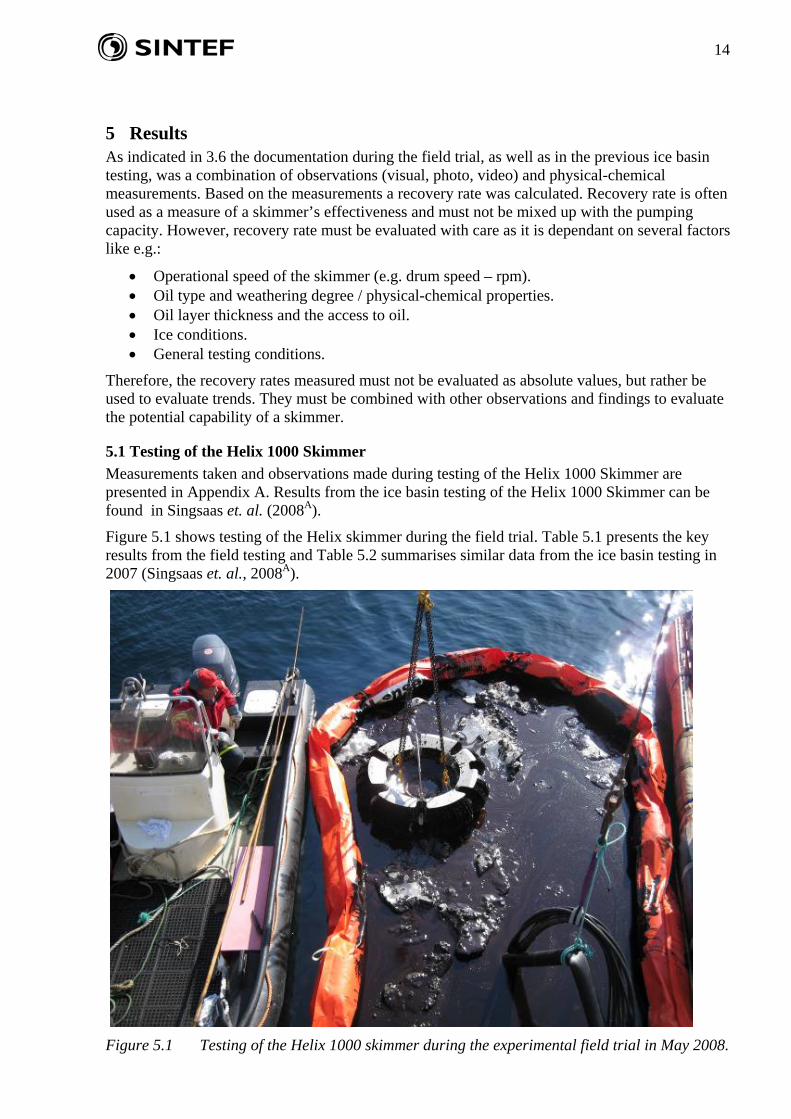
5.1 Testing of the Helix 1000 Skimmer Measurements taken and observations made during testing of the Helix 1000 Skimmer are presented in Appendix A. Results from the ice basin testing of the Helix 1000 Skimmer can be found in Singsaas et. al. (2008A).
Figure 5.1 shows testing of the Helix skimmer during the field trial. Table 5.1 presents the key results from the field testing and Table 5.2 summarises similar data from the ice basin testing in 2007 (Singsaas et. al., 2008A).
Figure 5.1 Testing of the Helix 1000 skimmer during the experimental field trial in May 2008.
15
Table 5.1 Results from field testing of the Helix 1000 Skimmer.
Test Ice Recovery Total Free Free Water in Total Emulsion Oilno. conditions time, min amount, l water, l water, % emulsion, % m3/hr. m3/hr. m3/hr.He 1 Broken, 10 % 12 590 152 26 47 3,0 2,2 1,2He 2 Broken, 30 % 16 527 36 7 53 2,0 1,8 0,9He 3 Broken, 60 % 13,5 132 0 0 53 0,6 0,6 0,3
Recovered liquid Recovery rate calculated
Table 5.2 Results from basin testing of the Helix 1000 skimmer (Singsaas et. al., 2008A).
Test Ice Recovery Total Free Free Water in Total Emulsion Oilno. conditions time, min amount, l water, l water, % emulsion, % m3/hr. m3/hr. m3/hr.B1 Broken, 50 % 52 1167 142 12 50 1,4 1,2 0,6B2 Slush, 100 % 15 1314 0 0 50 5,3 5,3 2,6
Recovered liquid Recovery rate calculated
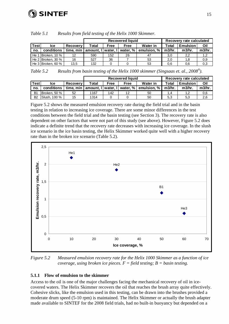
Figure 5.2 shows the measured emulsion recovery rate during the field trial and in the basin testing in relation to increasing ice coverage. There are some minor differences in the test conditions between the field trial and the basin testing (see Section 3). The recovery rate is also dependent on other factors that were not part of this study (see above). However, Figure 5.2 does indicate a definite trend that the recovery rate decreases with increasing ice coverage. In the slush ice scenario in the ice basin testing, the Helix Skimmer worked quite well with a higher recovery rate than in the broken ice scenario (Table 5.2).
0
0,5
1
1,5
2
2,5
0 10 20 30 40 50 60
Ice coverage, %
Emul
sion
reco
very
rate
, m3/
hr.
70
He1
He2
He3
B1
Figure 5.2 Measured emulsion recovery rate for the Helix 1000 Skimmer as a function of ice
coverage, using broken ice pieces. F = field testing; B = basin testing.
5.1.1 Flow of emulsion to the skimmer Access to the oil is one of the major challenges facing the mechanical recovery of oil in ice-covered waters. The Helix Skimmer recovers the oil that reaches the brush array quite effectively. Cohesive slicks, like the emulsion used in this testing, can be drawn into the brushes provided a moderate drum speed (5-10 rpm) is maintained. The Helix Skimmer or actually the brush adapter made available to SINTEF for the 2008 field trials, had no built-in buoyancy but depended on a
16
crane both for vertical and horizontal positioning. The skimmer worked in between the broken ice pieces and had to be repositioned at regular intervals when the oil layer around and flow into the skimmer reduced to a low critical level due to restrictions imposed by the ice.
5.1.2 Ice processing In this context, ice processing is defined as the skimmer’s ability to deflect the ice for easier access to the oil. The Helix Skimmer can process relatively small ice floes to a certain degree at low ice covers (approximately 0-40%). With increasing ice cover, the ice processing capability, as defined here, decreases. This is due to the configuration of the skimmer which then has to be moved around in the ice field in order to gain access to the oil.
5.1.3 Separation of oil, water and ice Uptake of free water by the Helix Skimmer is dependent on the vertical position of the skimmer in the water. Also brush speed will influence the water uptake. The uptake of free water varied between 0 and 26 % in the testing performed. During the field experiment, the submergence depth of the brushes in the water was estimated to be approximately 2 to 4 cm. During the field testing, the uptake of free water seemed to decrease with increasing ice coverage (Table 5.1). However, there are large uncertainties because it could be observed during the testing that the skimmer occasionally sank deeper into the water. This was due to the crane onboard the vessel that was not optimal for operation of these skimmers. It was also due to the Helix not having its own means of buoyancy. The weir was lower than the water surface when the skimmer was repositioned and it could be observed that the skimmer took up some free water during these operations. At the optimal vertical position and drum speed the Helix Skimmer will most probably discriminate well between oil and water.
Because of the construction of the skimmer, it can not take up ice pieces, but slush ice can enter the sump. The skimmer is equipped with a powerful screw auger pump which is able to transfer slush ice back to the receiving tank. No uptake of ice was measured or registered during these experiments.
5.1.4 Icing / freezing of equipment. According to the manufacturer, the Helix Skimmer is not constructed for cold conditions. During testing of the Helix skimmer in the field experiment, the temperatures were moderate (down to -4oC) and calm winds (up to 5 m/s). Therefore, the skimmer was not exposed to very challenging winter weather conditions. As long as the skimmer is in the water, the pump will not freeze. However in cold conditions the upper parts of the brushes are exposed to wind and low temperatures. Also the content in the discharge hose can freeze if it contains emulsion and/or free water and is left for some time, for instance during repair or in between uses. The skimmer needs to be modified before it is used under very cold conditions in the Arctic. An option could be to house the upper part of the brushes in a shield and to supply heat.
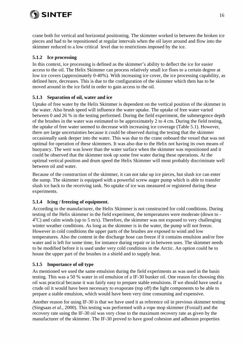
5.1.5 Importance of oil type As mentioned we used the same emulsion during the field experiments as was used in the basin testing. This was a 50 % water in oil emulsion of a IF-30 bunker oil. One reason for choosing this oil was practical because it was fairly easy to prepare stable emulsions. If we should have used a crude oil it would have been necessary to evaporate (top off) the light components to be able to prepare a stable emulsion, which would have been very time consuming and expensive.
Another reason for using IF-30 is that we have used it as reference oil in previous skimmer testing (Singsaas et al., 2000). This testing was performed with a rope mop skimmer (Foxtail) and the recovery rate using the IF-30 oil was very close to the maximum recovery rate as given by the manufacturer of the skimmer. The IF-30 proved to have good cohesion and adhesion properties
17
related to this skimmer type. Figure 5.3 shows the results from this testing, all results normalised to the IF-30 as the reference oil.
0
10
20
30
40
50
60
70
80
90
100
110
IF-30 Waxy, water free
Waxy,emulsion
Asphaltenic,emulsion
Naphtenic,water free
Naphtenic,emulsion
Paraffinic,emulsion
Rec
over
y ef
fect
iven
ess
in %
of t
he re
fere
nce
oil I
F-30
51%
29%
42%
100%104%
56%
24%
Figure 5.3 Testing of previous rope mop skimmer testing in the SINTEF basin, using IF-30 as
reference oil (Singsaas et al., 2000).
This testing indicates that IF-30 and emulsions of IF-30 can be close to optimal testing oil for skimmers that are dependant on good adhesion between the emulsion and the skimmer brushes and strong cohesion forces within the emulsion. However, for logistic and economic reasons it has not been within the scope of this project to do testing with several oil types. Even if ice processing seems to be the main challenge recovering oil in ice, the oil type and weathering degree still has a significant impact on the recovery effectiveness of different skimmer types.
5.1.6 Conclusions and recommendations The results from testing of the Helix 1000 Skimmer both in the ice basin and in the field indicate that it can be effective in collecting oil under the conditions found during the testing. Cohesive oil slicks can be effectively drawn into the brushes provided that the drum speed is not too high (5 – 10 rpm in these tests). The skimmer works best in low ice concentrations (up to 40 – 50 %) and might also have a potential for application alongside larger ice floes. This is a small skimmer and large recovery rates should not be expected, even in low ice concentrations. However, the principle of this skimmer, with rotating brush drums, seems to work quite well in ice. During the field experiments the Helix Skimmer proved to be a good tool when cleaning the boom of remaining oil after the experiments. Due to the size of the skimmer and its helical shape, it was possible to remove small amounts of emulsion from the “corners” of the boomed area.
The manufacturer of this skimmer is presently building a larger version of this skimmer with a hexagonical shape rather than the helical shape of the Helix Skimmer. The new skimmer will also contain improvements like “winterisation”, floating elements, umbilical for hoses etc. However, the Helix Skimmer can still be a versatile device for smaller oil spills in ice-covered waters. Based on this testing, the following recommendations have been made:
• The discharge hose and the hydraulic hoses are connected to the pump under water. They interfered with the flow of oil to the skimmer and with the ice around it. The hoses should
18
be connected on top of the skimmer which would also make it easier to operate the skimmer from a crane.
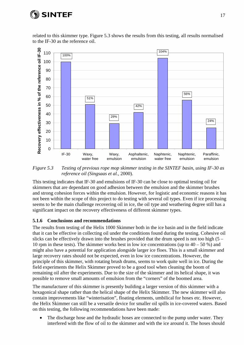
• Operation of the skimmer would benefit from built-in buoyancy of the skimmer. That would make it more independent of a crane for vertical positioning. The manufacturer has a flotation unit, consisting of three floating elements surrounding the skimmer (Figure 5.4). This in fact is the standard configuration in which the Helix is commercially available. These flotation units might impede the flow of oil to the brushes when operating in ice. Built-in flotation chambers would probably be a better solution when operating in ice. However, the existing floating units (Figure 5.4) should have been tested in ice as they might have a potential in low ice concentrations.
Figure 5.4 Flotation units for the Helix 1000 skimmer.
• The Helix Skimmer is relatively small and unprotected from weather and cold. The skimmer can be easily damaged if it is squeezed between ice floes. The new development of the hexagonical shaped skimmer by the manufacturer will have a grid surrounding the skimmer. , It is recommended that the Helix Skimmer be used under ice conditions where large pressure between ice floes is more unlikely to occur and where the skimmer is repositioned by a crane if it should happen.
• The Helix Skimmer has no heat enhancement that might facilitate oil collection and transfer. If the skimmer is going to be used under harsh conditions with low temperatures and/or strong winds, “winterisation” should be considered.
19
5.2 Testing of the LRB 150 Skimmer Measurements and observations performed during testing of the LRB 150 Skimmer are presented in Appendix B. Results from the ice basin testing of the LRB 150Skimmer are contained in Singsaas et. al., 2008B.
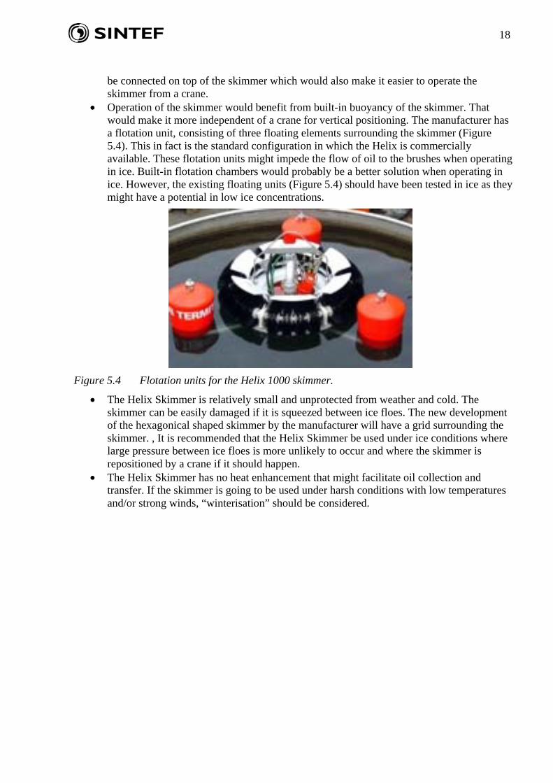
Figure 5.5 shows testing of the LRB 150 Skimmer during the field trial. Table 5.3 summarises the key results from the field testing and table 5.4 lists similar data from the ice basin testing in 2007 (Singsaas et. al., 2008B).
Figure 5.5 Testing of the LRB 150 skimmer during the experimental field trial in May 2008.
Table 5.3 Results from field testing of the LRB 150 skimmer.
Test Ice Recovery Total Free Free Water in Total Emulsion Oilno. conditions time, min amount, l water, l water, % emulsion, % m3/hr. m3/hr. m3/hr.
LRB 2 90 11 93 0 0 44 0,51 0,51 0,29LRB 3 70 18,5 501 0 0 55 1,62 1,62 0,73
Recovered Recovery rate calculated
Table 5.4 Results from basin testing of the LRB 150 skimmer (Singsaas et. al., 2008B).
Test Ice Recovery Total Free Free Water in Total Emulsion Oilno. conditions time, min amount, l water, l water, % emulsion, % m3/hr. m3/hr. m3/hr.B1 No ice 14 2342 0 0 45 10,0 10,0 5,5B2 Broken, 50 % 19 1090 55 5 50 3,4 3,3 1,6B3 Slush, 100 % 14 2163 108 5 50 9,3 8,8 4,4
Recovered liquid Recovery rate calculated
20
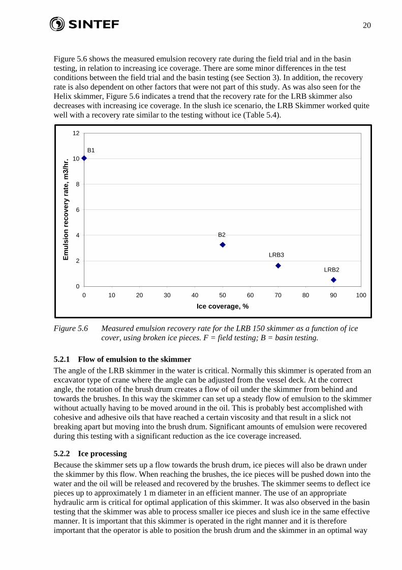
Figure 5.6 shows the measured emulsion recovery rate during the field trial and in the basin testing, in relation to increasing ice coverage. There are some minor differences in the test conditions between the field trial and the basin testing (see Section 3). In addition, the recovery rate is also dependent on other factors that were not part of this study. As was also seen for the Helix skimmer, Figure 5.6 indicates a trend that the recovery rate for the LRB skimmer also decreases with increasing ice coverage. In the slush ice scenario, the LRB Skimmer worked quite well with a recovery rate similar to the testing without ice (Table 5.4).
0
2
4
6
8
10
12
0 10 20 30 40 50 60 70 80 90 100
Ice coverage, %
Emul
sion
reco
very
rate
, m3/
hr.
LRB2
LRB3
B2
B1
Figure 5.6 Measured emulsion recovery rate for the LRB 150 skimmer as a function of ice
cover, using broken ice pieces. F = field testing; B = basin testing.
5.2.1 Flow of emulsion to the skimmer The angle of the LRB skimmer in the water is critical. Normally this skimmer is operated from an excavator type of crane where the angle can be adjusted from the vessel deck. At the correct angle, the rotation of the brush drum creates a flow of oil under the skimmer from behind and towards the brushes. In this way the skimmer can set up a steady flow of emulsion to the skimmer without actually having to be moved around in the oil. This is probably best accomplished with cohesive and adhesive oils that have reached a certain viscosity and that result in a slick not breaking apart but moving into the brush drum. Significant amounts of emulsion were recovered during this testing with a significant reduction as the ice coverage increased.
5.2.2 Ice processing Because the skimmer sets up a flow towards the brush drum, ice pieces will also be drawn under the skimmer by this flow. When reaching the brushes, the ice pieces will be pushed down into the water and the oil will be released and recovered by the brushes. The skimmer seems to deflect ice pieces up to approximately 1 m diameter in an efficient manner. The use of an appropriate hydraulic arm is critical for optimal application of this skimmer. It was also observed in the basin testing that the skimmer was able to process smaller ice pieces and slush ice in the same effective manner. It is important that this skimmer is operated in the right manner and it is therefore important that the operator is able to position the brush drum and the skimmer in an optimal way
21
given the oil and ice conditions. This could involve, for example, advancing the brush drum in one direction so that oil and ice were “processed” on a continuous basis.
5.2.3 Separation of oil, water and ice Very low uptakes of free water were measured in these tests (Tables 5.3 and 5.4). The speed of the brush drum was relatively low in this testing (5 – 10 rpm). The submergence depth was estimated to be 2 to 5 cm. Due to the position of the LRB Skimmer brush drum and receiving sump, it is anticipated that the uptake of free water is less sensitive to both the submergence depth and the rotational speed compared to the Helix without buoyancy chambers. However, no systematic studies of drum speed or submergence depth were performed as part of this testing.
The LRB Skimmer did not pick up ice pieces during operation and nor was any uptake of slush ice registered. The skimmer is equipped with a screw auger pump powerful enough to handle both slush ice and smaller ice pieces.
5.2.4 Icing / freezing of equipment. The LRB Skimmer, like the Helix, was not subjected to extreme weather conditions during this testing. Subsequent to the basin testing in 2007, the manufacturer had installed heating units in the scraper mechanism prior to the field experiment. However, due to the moderate temperatures during the field trial (air temperatures around -1 to -2oC), the heating was not investigated during this testing.
5.2.5 Conclusions and recommendations It can be concluded that the LRB Skimmer represents state-of-the-art technology for the recovery of oil spills in an ice field. By using the original intended excavator crane and an experienced operator, this skimmer is expected to have the potential to effectively recover oil in ice up to ice covers of 60 – 70 %. The crane onboard Lance was not optimal for skimmer testing and for the LRB skimmer the angle of the skimmer could not be changed during testing. The discharge hose and the hydraulic hoses interfered with the oil and the ice and it was difficult to hold the skimmer in an optimal position. In the commercial complete LRB Skimmer package, the hoses are incorporated in the hydraulic arm that deploys and manoeuvres the skimmer.
Due to the flow created under the brush drum, the skimmer exhibited good ice processing capabilities with low uptake of free water. A short test with cleaning off oiled ice surfaces revealed the skimmer to also be capable of this task. The LRB Skimmer has to be operated by a crane in the immediate vicinity of a vessel. Under certain conditions, this can be a drawback as a vessel tends to open up the ice field and hence spreading of the oil to thinner oil thicknesses.
22
5.3 Testing of the SeaMop 4090 Skimmer Testing of a Rope Mop Skimmer was requested by members of the project Reference Group as it is currently included in the oil spill contingency for Arctic areas. It was not included in the ice basin testing performed in 2007 because it has been extensively tested through earlier projects (see Johannessen et al., 1996). The oleophilic rope principle has demonstrated its effectiveness in removing medium viscosity oils in low wave conditions and in debris and ice.
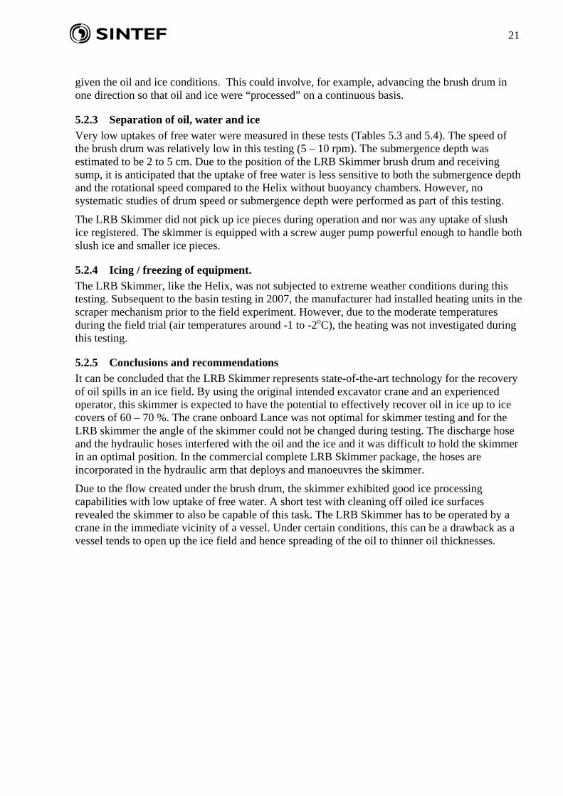
Testing of the Helix and LRB skimmers was given priority during the tight schedule of the field testing. The SeaMop Skimmer was subjected to only limited testing during the field trial. Appendix C gives measurements and observations from the two SeaMop tests. Figure 5.7 shows testing of the SeaMop Skimmer during the field trial. Table 5.5 summarises the key results from the field testing.
Figure 5.7 Testing of the SeaMop 4090 skimmer during the experimental field trial in May
2008.
Table 5.5 Results from the limited field testing of the SeaMop 4090 skimmer.
Test Ice Recovery Total Free Free Water in Total Emulsion Oilno. conditions time, min amount, l water, l water, % emulsion, % m3/hr. m3/hr. m3/hr.SM1 Broken, 60 % 15 NA NA NA NASM2 Broken, 60 % 15 546 160 29 53 2,2 1,5 0,7
Recovered liquid Recovery rate calculated
Priming of rope mops with oil
23
5.3.1 Flow of emulsion to the skimmer A certain flow of emulsion to the rope mops was observed, but this was somewhat restricted due to the high ice cover. The crane onboard Lance was not optimal for moving the rope mops over the test area. In past testing, the rotational speed of the mops was matched with the speed of their advance over the oily area through the use of a dedicated crane. This zero relative velocity (ZRV) method resulted in the immersion of the mops into the oil, with good flow of oil to the rope mops, even in ice. In this experiment, approximately 2 m, out of the total length of the rope mops or 15 m, was in contact with the oil, water and ice at any one time.
5.3.2 Ice processing Processing of the ice floes was observed to a certain degree by the rope mops being able to move ice floes around and by the mops being made to “walk” over the ice. However, due to the relatively high ice cover (approximately 60%) ice processing was somewhat restricted. Again, a more appropriate crane would most probably have contributed to more effective ice processing. The mops were observed to remove oil that coated smooth ice, but would be expected to be less effective in removing oil from rough and jagged ice pieces.
5.3.3 Separation of oil, water and ice After the rope mops were primed with oil, they coated well with the oil they did contact. The rope mops also took up free water, but some of the water (and likely some of the oil) dripped off the mops on their way from the water surface up to the oil collector and wringer. A free water uptake of approximately 29% was measured in this test. This is a fairly high water uptake compared to the brush drum skimmers.
No uptake of ice was measured in this test. Due to the height from the water surface to the skimmer it would be very unlikely that ice pieces would be lifted that high. It has been observed, however, that ice crystals can form from free water on the way up to the wringer, in cold weather combined with strong winds. Due to the prevailing good weather conditions during this test, ice formation was not observed.
5.3.4 Icing / freezing of equipment. As for the other skimmers tested, the Rope Mop Skimmer was not subjected to extreme weather conditions during this testing. Therefore no icing or freezing of the equipment was observed.
5.3.5 Conclusions and recommendations Rope mop skimmers have been tested on several occasions in the past, also in ice and under cold conditions. It has been concluded that the concept has a high potential for recovering oil in ice (Johannessen et al., 1996). The concept has also been adapted to more local and specific conditions, for example to collect oil in trenches in the ice by moving the rope mop horizontally in the trench. The very limited test performed during the field experiment demonstrated the ability of the rope mops to coat with the emulsion used during this testing and lift it to the wringer mechanism.
Rope mop skimmers are oleophilic devices that depend on the oil adhering to the mops. Past experiments, also at SINTEF, have shown that their effectiveness is dependent on the oil type and properties of the emulsion being recovered (Singsaas et al., 2000) (see also 5.1.5). At the same time, cohesion is also important. These are attractive forces acting within the oil/emulsion, and because the oil/emulsion has to be lifted several metres cohesion is important to avoid dripping of oil on the way up to the wringing mechanism. In this test, there was only a limited amount of emulsion dripping off the rope mop on the way up to the skimmer unit.
Often when using a rope mop skimmer from a vessel side, the height from the sea surface and up to the skimmer unit can be several metres (typically +/- 6 m). This results in a large surface of the
24
rope mops being exposed to air at any time. In low temperatures and strong winds, this can result in freezing of free water in the rope mops. Most rope mop skimmers are exposed to freezing under such extreme conditions when suspended in the air. Past reports have included recommendations to “winterise” these skimmers. The SeaMop 4090 is equipped with a small manifold that can supply hot water spray to heat the mops as they exit the machine as well as adding water to the oil being collected to promote transfer by the pump. In addition, a tarpaulin can be used to cover the sump of the skimmer and contribute to decreasing the possibility for freezing of rollers, wringers and the pump.
6 Conclusions and lessons learned The main objective of this project was to document the capability and potential of commercially available skimmers for recovering oil in ice. Based on this documentation, suggestions should be possible for defining and improving the operational spill response window in ice and cold conditions. The testing, both in the SINTEF ice basin and during the 2008 field trial, should also lead to a better understanding of the potential use of these skimmers in ice-covered waters. An additional objective for the 2008 field experiments was to gain practical experience prior to the planned field trial in 2009.
6.1 Final conclusions from the skimmer testing Based on the testing performed during the field experiment in 2008 and previous testing performed in the SINTEF ice basin in March to June 2007, the following overall conclusions have been drawn:
Ro-Clean Desmi Helix 1000 Skimmer: The results from testing of the Helix 1000 Skimmer both in the ice basin and in the field indicate that it can be effective in collecting oil under the conditions found during the testing. Cohesive oil slicks can be effectively drawn into the brushes provided that the drum speed is not too high (5 – 10 rpm in these tests). The skimmer works best in low ice concentrations (up to 40 – 50 %) and might also have a potential for application alongside larger ice floes. This is a small skimmer and large recovery rates should not be expected, even in low ice concentrations. However, the principle of this skimmer, with rotating brush drums, seems to work quite well in ice. During the field experiments the Helix Skimmer proved to be a good tool when cleaning inside the boom of remaining oil after the experiments. Due to the size of the skimmer and its helical shape, it was possible to remove small amounts of emulsion from the “corners” of the boomed area.
The manufacturer of this skimmer is presently building a larger version of this skimmer with a hexagonical shape rather than the helical shape of the Helix Skimmer. The new skimmer will also contain improvements like “winterisation”, floating elements, umbilical for hoses etc. However, the Helix Skimmer can still be a versatile device for smaller oil spills in ice-covered waters.
Lamor LRB 150 Skimmer: It can be concluded that the LRB Skimmer represents state-of-the-art technology for the recovery of oil spills in an ice field. By using the original intended excavator crane and an experienced operator, this skimmer is expected to have the potential to effectively recover oil in ice up to ice covers of 60 – 70 %. The crane onboard Lance was not optimal for skimmer testing and for the LRB skimmer the angle of the skimmer could not be changed during testing. The discharge hose and the hydraulic hoses interfered with the oil and the ice and it was difficult to hold the skimmer in an optimal position. In the commercial complete LRB Skimmer package, the hoses are incorporated in the hydraulic arm that deploys and manoeuvres the skimmer.
Due to the flow created under the drum brush, the skimmer exhibited good ice processing capabilities with low uptake of free water. A short test with cleaning off oiled ice surfaces
25
revealed the skimmer to also be capable of this task. The LRB Skimmer has to be operated by a crane in the immediate vicinity of a vessel. Under certain conditions, this can be a drawback as a vessel tends to open up the ice field and hence spreading of the oil to thinner oil thicknesses.
Ro-Clean Desmi SeaMop 4090 Skimmer: Rope mop skimmers have been tested on several occasions in the past, also in ice and under cold conditions. It has been concluded that the concept has a high potential for recovering oil in ice (Johannessen et al., 1996). The concept has also been adapted to more local and specific conditions, for example to collect oil in trenches in the ice by moving the rope mop horizontally in the trench. The very limited test performed during the field experiment demonstrated the ability of the rope mops to coat with the emulsion used during this testing and lift it to the wringer mechanism.
Rope mop skimmers are oleophilic devices that depend on the oil adhering to the mops. Past experiments, also at SINTEF (Singsaas et al., 2000), have shown that their effectiveness is dependent on the oil type and properties of the emulsion being recovered. At the same time, cohesion is also important. These are attractive forces acting within the oil/emulsion, and because the oil/emulsion has to be lifted several metres cohesion is important to avoid dripping of oil on the way up to the wringing mechanism. In this test, there was only a limited amount of emulsion dripping off the rope mop on the way up to the skimmer unit.
Often when using a rope mop skimmer from a vessel side, the height from the sea surface and up to the skimmer unit can be several metres (typically +/- 6 m). This results in a large surface of the rope mops being exposed to air at any time. In low temperatures and strong winds, this can result in freezing of free water in the rope mops. Most rope mop skimmers are exposed to freezing under such extreme conditions when suspended in the air. Past reports have included recommendations to “winterise” these skimmers. The SeaMop 4090 is equipped with a small manifold that can supply hot water spray to heat the mops as they exit the machine as well as adding water to the oil being collected to promote transfer by the pump. In addition, a tarpaulin can be used to cover the sump of the skimmer and contribute to decreasing the possibility for freezing of rollers, wringers and the pump.
Relevance of oil type and ice regime
An IF-30 water in oil emulsion with approximately 50 % water was used both in the basin testing and in the field testing. When it comes to adhesion of oil to the brushes and cohesion forces within the emulsion, the IF-30 is probably close to optimal testing oil for these skimmers. However, for logistic and economic reasons it has not been within the scope of this project to do testing with different oil types. Even if ice processing seems to be the main challenge recovering oil in ice, the oil type and weathering degree still has a significant impact on the recovery effectiveness of different skimmer types.
The target ice cover in these experiments was 30 – 50 % broken ice pieces and floes in addition to the slush ice scenario used in the basin testing. The actual ice regime will have a major impact on the skimmer recovery effectiveness. When referring to 50 % broken ice conditions in this study we mean ice floes of a size up to approximately 1 – 1.5 meter in diameter. Under real conditions in the Arctic 50 % ice coverage normally means that half the sea surface in a given area is covered with ice floes with a diameter of several meter and up to several hundreds of meters. Existing skimmers can only process ice floes/pieces up to only a couple of meters in diameter and needs to circumnavigate larger ice floes. To investigate a skimmer’s ability to process ice and to recover oil within the ice, the chosen ice regimes for testing seem appropriate. However, in a scenario with 50 % ice coverage and with large ice floes present a skimmer can operate in fairly large ice free areas between the ice floes which resemble open waters conditions, most likely with less wave action. Given for instance a blow out under these conditions traditional skimmers can probably work well with high recovery rates in fairly high oil thicknesses with the ice acting as a
26
natural confinement. Reduced recovery rates will then be experienced if the oil thickness is low due to large spreading of the oil or there are smaller ice floes/pieces or slush ice between the larger ice floes restricting the flow of oil to the skimmer.
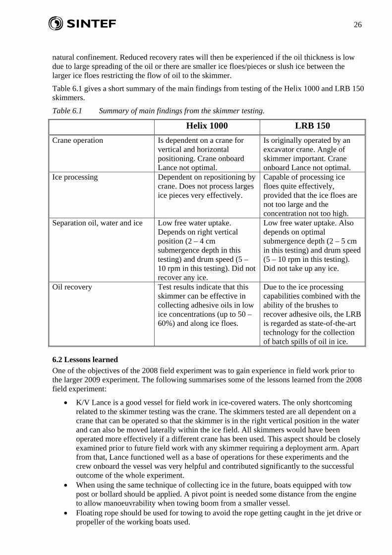
Table 6.1 gives a short summary of the main findings from testing of the Helix 1000 and LRB 150 skimmers.
Table 6.1 Summary of main findings from the skimmer testing.
Helix 1000 LRB 150 Crane operation Is dependent on a crane for
vertical and horizontal positioning. Crane onboard Lance not optimal.
Is originally operated by an excavator crane. Angle of skimmer important. Crane onboard Lance not optimal.
Ice processing Dependent on repositioning by crane. Does not process larges ice pieces very effectively.
Capable of processing ice floes quite effectively, provided that the ice floes are not too large and the concentration not too high.
Separation oil, water and ice Low free water uptake. Depends on right vertical position (2 – 4 cm submergence depth in this testing) and drum speed (5 – 10 rpm in this testing). Did not recover any ice.
Low free water uptake. Also depends on optimal submergence depth (2 – 5 cm in this testing) and drum speed (5 – 10 rpm in this testing). Did not take up any ice.
Oil recovery Test results indicate that this skimmer can be effective in collecting adhesive oils in low ice concentrations (up to 50 – 60%) and along ice floes.
Due to the ice processing capabilities combined with the ability of the brushes to recover adhesive oils, the LRB is regarded as state-of-the-art technology for the collection of batch spills of oil in ice.
6.2 Lessons learned One of the objectives of the 2008 field experiment was to gain experience in field work prior to the larger 2009 experiment. The following summarises some of the lessons learned from the 2008 field experiment:
• K/V Lance is a good vessel for field work in ice-covered waters. The only shortcoming related to the skimmer testing was the crane. The skimmers tested are all dependent on a crane that can be operated so that the skimmer is in the right vertical position in the water and can also be moved laterally within the ice field. All skimmers would have been operated more effectively if a different crane has been used. This aspect should be closely examined prior to future field work with any skimmer requiring a deployment arm. Apart from that, Lance functioned well as a base of operations for these experiments and the crew onboard the vessel was very helpful and contributed significantly to the successful outcome of the whole experiment.
• When using the same technique of collecting ice in the future, boats equipped with tow post or bollard should be applied. A pivot point is needed some distance from the engine to allow manoeuvrability when towing boom from a smaller vessel.
• Floating rope should be used for towing to avoid the rope getting caught in the jet drive or propeller of the working boats used.
27
• The Norlense 35F boom used a double set of loops and rope as a connector. This was
time-consuming to use at water level. An ASTM, Universal, Navy or other slide or simple mechanism should be used in the future for connecting section ends. This is especially important when the boom is in the water and contaminated with oil.
• Paravanes, tow floats or bridles attached to connectors would improve and speed up towing when collecting ice.
• Representatives from the manufacturers must be highly competent and knowledgeable persons who are capable of troubleshooting and making repairs and modifications that might be required in the field. Representatives from: Lamor, Ro-Clean Desmi and Norlense, participated during the 2008 field trial and worked well together providing key input to the testing.
7 Acknowledgement The crew on MV “Lance” were highly competent in operating the crane, the main vessel and the working boats. The representatives from the manufacturers are also acknowledged: Erik Refsgaard from Ro-Clean Desmi, Rune Høgstrøm from Lamor and Svein-Bjarne Olsen from Norlense, all of whom worked very hard and well in preparing and performing the testing and subsequent cleanup.
8 References Johannessen, B.O., Jensen, H., Solsberg, L., Lorenzo, T., 1996: Mechanical Oil Recovery in Ice
Infested Waters (MORICE) – Phase 1. SINTEF Report no.: STF22 F96225. Restricted.
Singsaas, I., Daling, P.S., Moldestad, M.Ø., Jensen, H.V., 2000: Samlerapport: Effektivitet av Foxtail skimmer på IF-30 bunkersolje og forvitret Ula, Balder, Jotun og Troll råoljer. SINTEF report no.: SFT66 A00082. Open. In Norwegian.
Singsaas, I., Leirvik, F., Johansen, B., 2008A: Testing of Ro-Clean Desmi Ice skimmer and Helix skimmer in SINTEF ice basin. “Oil in ice” JIP, task 3.1: Testing of existing concepts.
Singsaas, I., Leirvik, F., Johansen, B., 2008B: Testing of Lamor GT 185 skimmer and LRB 150 skimmers in SINTEF ice basin. “Oil in ice” JIP, task 3.1: Testing of existing concepts.
Singsaas, I., Leirvik, F., Johansen, B., 2008C: Testing of Framo HiWax skimmer in SINTEF ice basin. “Oil in ice” JIP, task 3.1: Testing of existing concepts.
28
Appendix A: Helix Skimmer test 21. May 2008. Position (12.00): N 76.48 E 29.20
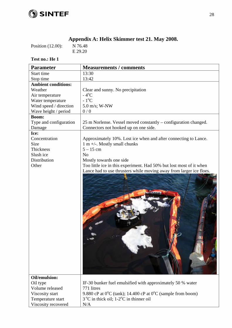
Test no.: He 1
Parameter Measurements / comments Start time Stop time
13:30 13:42
Ambient conditions: Weather Air temperature Water temperature Wind speed / direction Wave height / period
Clear and sunny. No precipitation - 4oC - 1oC 5.0 m/s; W-NW 0 / 0
Boom: Type and configuration Damage
25 m Norlense. Vessel moved constantly – configuration changed. Connectors not hooked up on one side.
Ice: Concentration Size Thickness Slush ice Distribution Other
Approximately 10%. Lost ice when and after connecting to Lance. 1 m +/-. Mostly small chunks 5 – 15 cm No Mostly towards one side Too little ice in this experiment. Had 50% but lost most of it when Lance had to use thrusters while moving away from larger ice floes.
Oil/emulsion: Oil type Volume released Viscosity start Temperature start Viscosity recovered
IF-30 bunker fuel emulsified with approximately 50 % water 771 litres 9.880 cP at 0oC (tank); 14.400 cP at 0oC (sample from boom) 3 oC in thick oil; 1-2oC in thinner oil N/A
29
Thickness start Thickness after recovery Water content start Water content recovered
Measured to 2 cm Estimated to approximately 1 cm 47%
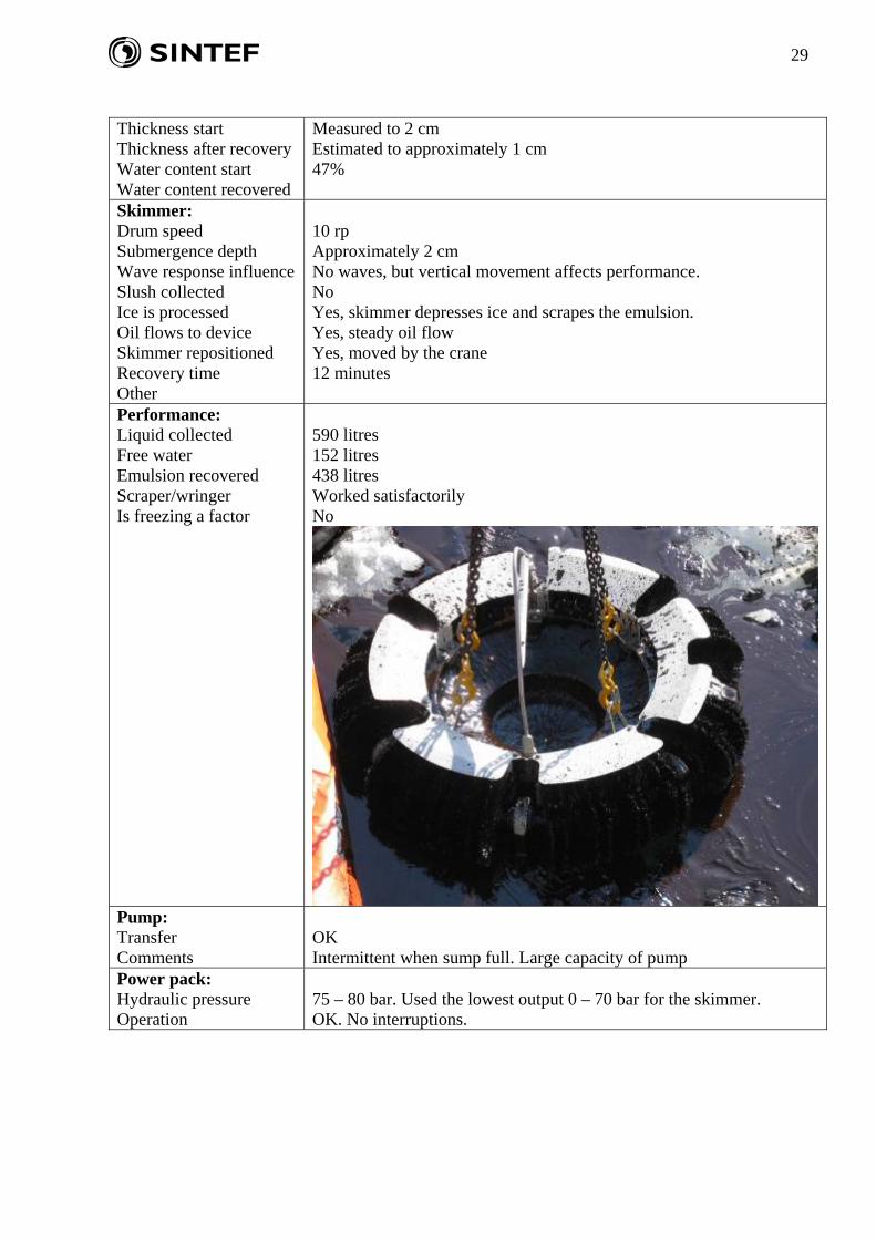
Skimmer: Drum speed Submergence depth Wave response influence Slush collected Ice is processed Oil flows to device Skimmer repositioned Recovery time Other
10 rp Approximately 2 cm No waves, but vertical movement affects performance. No Yes, skimmer depresses ice and scrapes the emulsion. Yes, steady oil flow Yes, moved by the crane 12 minutes
Performance: Liquid collected Free water Emulsion recovered Scraper/wringer Is freezing a factor
590 litres 152 litres 438 litres Worked satisfactorily No
Pump: Transfer Comments
OK Intermittent when sump full. Large capacity of pump
Power pack: Hydraulic pressure Operation
75 – 80 bar. Used the lowest output 0 – 70 bar for the skimmer. OK. No interruptions.
30
Test no.: He 2
Parameter Measurements / comments Start time Stop time
14:26 14:42
Ambient conditions: Weather Air temperature Water temperature Wind speed / direction Wave height / period
Clear and sunny. No precipitation - 4oC - 1,4oC 5.0 m/s; N-NE 0 / 0
Boom: Type and configuration Damage
25 m Norlense. Vessel moved constantly – configuration changed. Connectors not hooked up on one side.
Ice: Concentration Size Thickness Slush ice Distribution
Initially 10%, but 30 – 40% when boomed area narrowed down. 5 – 100 cm. Pieces varyary in size 5 – 15 cm No Evenly when boomed area narrowed
Oil/emulsion: Oil type Volume released Viscosity start Temperature start Viscosity recovered Thickness start Thickness after recovery Water content start Water content recovered
IF-30 bunker fuel emulsified with approximately 50% water. 437 litres added to existing oil. Total estimated volume: 770 litres. 13.600 cP at 0oC 4-5oC in thick oil; 2-3oC in thinner oil 13.100 cP at 0oC. Estimated to 2 cm – 4 cm when boomed area narrowed Estimated to be approximately 1 cm – 2 cm when boomed area narrowed N/A 53%
Skimmer: Drum speed Submergence depth Wave response influence Slush collected Ice is processed Oil flows to device Skimmer repositioned Recovery time
6 rpm Approximately 2 cm No waves, but vertical movement affects performance No No, oil flow into skimmer when repositioned Yes Yes, moved by the crane 16 minutes. Some stop time during operation.
Performance: Liquid collected Free water Emulsion recovered Scraper/wringer Is freezing a factor
527 litres 36 litres 491 litres Worked satisfactorily No
Pump: Transfer Comments
OK Intermittent when sump full. Large capacity of pump.
Power pack: Hydraulic pressure Operation
75 – 80 bar. Used the lowest output 0 – 70 bar for the skimmer. OK. No interruptions.
31
Appendix B: LRB Skimmer tests 23. May 2008. Position (12.00): N 76.51 E 29.47
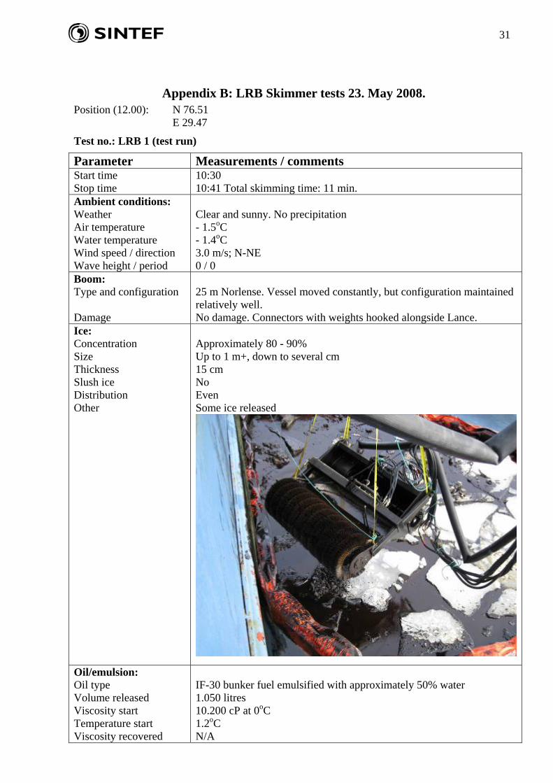
Test no.: LRB 1 (test run)
Parameter Measurements / comments Start time Stop time
10:30 10:41 Total skimming time: 11 min.
Ambient conditions: Weather Air temperature Water temperature Wind speed / direction Wave height / period
Clear and sunny. No precipitation - 1.5oC - 1.4oC 3.0 m/s; N-NE 0 / 0
Boom: Type and configuration Damage
25 m Norlense. Vessel moved constantly, but configuration maintained relatively well. No damage. Connectors with weights hooked alongside Lance.
Ice: Concentration Size Thickness Slush ice Distribution Other
Approximately 80 - 90% Up to 1 m+, down to several cm 15 cm No Even Some ice released
Oil/emulsion: Oil type Volume released Viscosity start Temperature start Viscosity recovered
IF-30 bunker fuel emulsified with approximately 50% water 1.050 litres 10.200 cP at 0oC 1.2oC N/A
32
Thickness start Thickness after recovery Water content start Water content recovered
5-10 cm depending on position inside the boom N/A 44% N/A
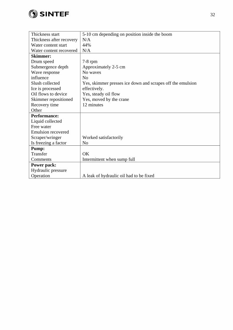
Skimmer: Drum speed Submergence depth Wave response influence Slush collected Ice is processed Oil flows to device Skimmer repositioned Recovery time Other
7-8 rpm Approximately 2-5 cm No waves No Yes, skimmer presses ice down and scrapes off the emulsion effectively. Yes, steady oil flow Yes, moved by the crane 12 minutes
Performance: Liquid collected Free water Emulsion recovered Scraper/wringer Is freezing a factor
Worked satisfactorily No
Pump: Transfer Comments
OK Intermittent when sump full
Power pack: Hydraulic pressure Operation
A leak of hydraulic oil had to be fixed
33
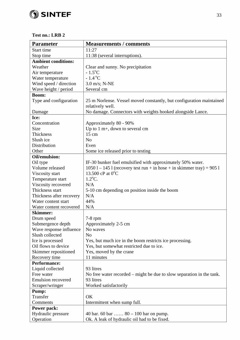
Test no.: LRB 2
Parameter Measurements / comments Start time Stop time
11:27 11:38 (several interruptions).
Ambient conditions: Weather Air temperature Water temperature Wind speed / direction Wave height / period
Clear and sunny. No precipitation - 1.5oC - 1.4 oC 3.0 m/s; N-NE Several cm
Boom: Type and configuration Damage
25 m Norlense. Vessel moved constantly, but configuration maintained relatively well. No damage. Connectors with weights hooked alongside Lance.
Ice: Concentration Size Thickness Slush ice Distribution Other
Approximately 80 - 90% Up to 1 m+, down to several cm 15 cm No Even Some ice released prior to testing
Oil/emulsion: Oil type Volume released Viscosity start Temperature start Viscosity recovered Thickness start Thickness after recovery Water content start Water content recovered
IF-30 bunker fuel emulsified with approximately 50% water. 1050 l – 145 l (recovery test run + in hose + in skimmer tray) = 905 l 13.500 cP at 0oC 1.2oC. N/A 5-10 cm depending on position inside the boom N/A 44% N/A
Skimmer: Drum speed Submergence depth Wave response influence Slush collected Ice is processed Oil flows to device Skimmer repositioned Recovery time
7-8 rpm Approximately 2-5 cm No waves No Yes, but much ice in the boom restricts ice processing. Yes, but somewhat restricted due to ice. Yes, moved by the crane 11 minutes
Performance: Liquid collected Free water Emulsion recovered Scraper/wringer
93 litres No free water recorded – might be due to slow separation in the tank. 93 litres Worked satisfactorily
Pump: Transfer Comments
OK Intermittent when sump full.
Power pack: Hydraulic pressure Operation
40 bar. 60 bar …… 80 – 100 bar on pump. Ok. A leak of hydraulic oil had to be fixed.
34
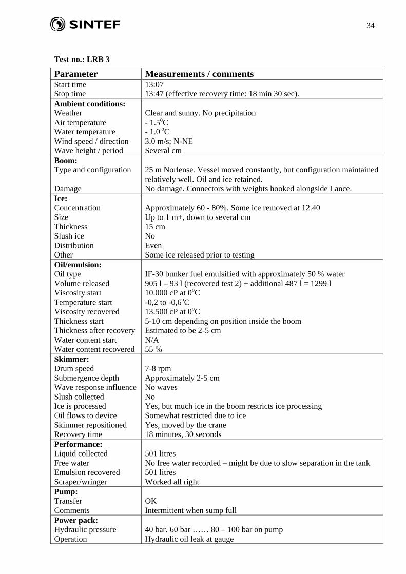
Test no.: LRB 3
Parameter Measurements / comments Start time Stop time
13:07 13:47 (effective recovery time: 18 min 30 sec).
Ambient conditions: Weather Air temperature Water temperature Wind speed / direction Wave height / period
Clear and sunny. No precipitation - 1.5oC - 1.0 oC 3.0 m/s; N-NE Several cm
Boom: Type and configuration Damage
25 m Norlense. Vessel moved constantly, but configuration maintained relatively well. Oil and ice retained. No damage. Connectors with weights hooked alongside Lance.
Ice: Concentration Size Thickness Slush ice Distribution Other
Approximately 60 - 80%. Some ice removed at 12.40 Up to 1 m+, down to several cm 15 cm No Even Some ice released prior to testing
Oil/emulsion: Oil type Volume released Viscosity start Temperature start Viscosity recovered Thickness start Thickness after recovery Water content start Water content recovered
IF-30 bunker fuel emulsified with approximately 50 % water 905 l – 93 l (recovered test 2) + additional 487 l = 1299 l 10.000 cP at 0oC -0,2 to -0,6oC 13.500 cP at 0oC 5-10 cm depending on position inside the boom Estimated to be 2-5 cm N/A 55 %
Skimmer: Drum speed Submergence depth Wave response influence Slush collected Ice is processed Oil flows to device Skimmer repositioned Recovery time
7-8 rpm Approximately 2-5 cm No waves No Yes, but much ice in the boom restricts ice processing Somewhat restricted due to ice Yes, moved by the crane 18 minutes, 30 seconds
Performance: Liquid collected Free water Emulsion recovered Scraper/wringer
501 litres No free water recorded – might be due to slow separation in the tank 501 litres Worked all right
Pump: Transfer Comments
OK Intermittent when sump full
Power pack: Hydraulic pressure Operation
40 bar. 60 bar …… 80 – 100 bar on pump Hydraulic oil leak at gauge
35
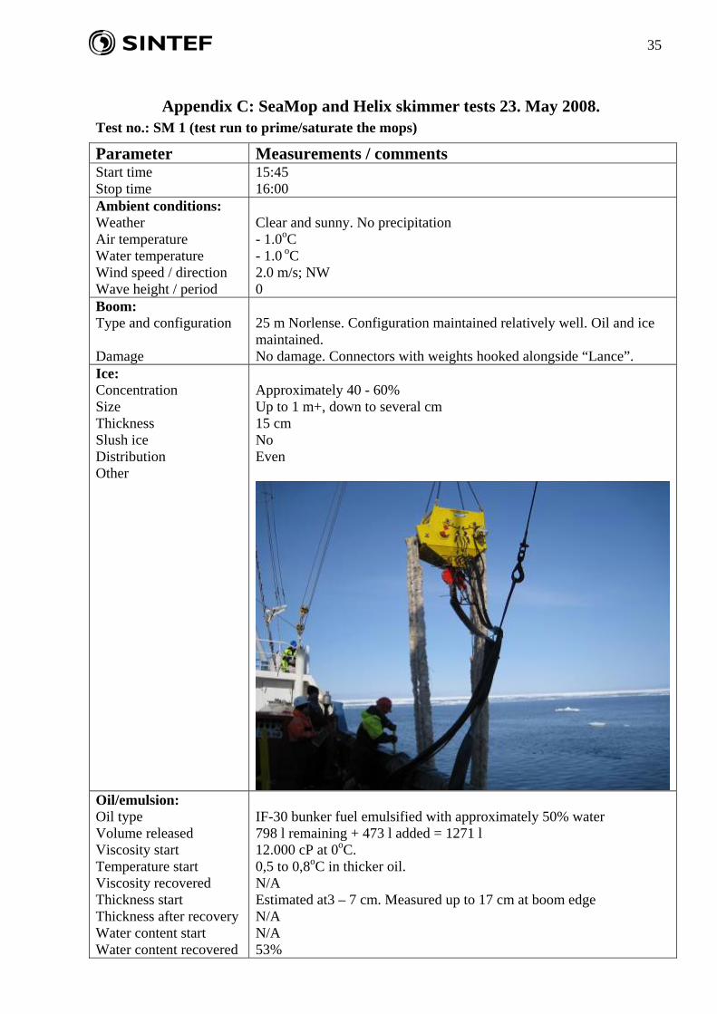
Appendix C: SeaMop and Helix skimmer tests 23. May 2008.
Test no.: SM 1 (test run to prime/saturate the mops)
Parameter Measurements / comments Start time Stop time
15:45 16:00
Ambient conditions: Weather Air temperature Water temperature Wind speed / direction Wave height / period
Clear and sunny. No precipitation - 1.0oC - 1.0 oC 2.0 m/s; NW 0
Boom: Type and configuration Damage
25 m Norlense. Configuration maintained relatively well. Oil and ice maintained. No damage. Connectors with weights hooked alongside “Lance”.
Ice: Concentration Size Thickness Slush ice Distribution Other
Approximately 40 - 60% Up to 1 m+, down to several cm 15 cm No Even
Oil/emulsion: Oil type Volume released Viscosity start Temperature start Viscosity recovered Thickness start Thickness after recovery Water content start Water content recovered
IF-30 bunker fuel emulsified with approximately 50% water 798 l remaining + 473 l added = 1271 l 12.000 cP at 0oC. 0,5 to 0,8oC in thicker oil. N/A Estimated at3 – 7 cm. Measured up to 17 cm at boom edge N/A N/A 53%

36
Skimmer: Drum speed Submergence depth Wave response influence Slush collected Ice is processed Oil flows to device Skimmer repositioned Recovery time Other
15 metres/minute 2 m of each mop in liquid No waves No Yes, but much ice in the boom restricts ice processing. Yes, but somewhat restricted due to ice. Yes, moved by the crane. 15 minutes
Performance: Liquid collected Free water Emulsion recovered Scraper/wringer Is freezing a factor
Not measured – only priming of mops No free water recorded – might be due to slow separation in the tank. Not measured No
Pump: Transfer Comments
OK Intermittent when sump full.
Power pack: Hydraulic pressure Operation
75-80 bar for mops. 100 bar on pump. Hydraulic oil leak at gauge
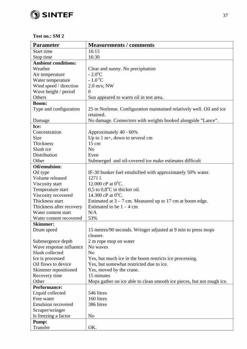
37
Test no.: SM 2
Parameter Measurements / comments Start time Stop time
16:15 16:30
Ambient conditions: Weather Air temperature Water temperature Wind speed / direction Wave height / period Others
Clear and sunny. No precipitation - 2.0oC - 1.0 oC 2.0 m/s; NW 0 Sun appeared to warm oil in test area.
Boom: Type and configuration Damage
25 m Norlense. Configuration maintained relatively well. Oil and ice retained. No damage. Connectors with weights hooked alongside “Lance”.
Ice: Concentration Size Thickness Slush ice Distribution Other
Approximately 40 - 60% Up to 1 m+, down to several cm 15 cm No Even Submerged and oil-covered ice make estimates difficult
Oil/emulsion: Oil type Volume released Viscosity start Temperature start Viscosity recovered Thickness start Thickness after recovery Water content start Water content recovered
IF-30 bunker fuel emulsified with approximately 50% water. 1271 l. 12.000 cP at 0oC. 0,5 to 0,8oC in thicker oil. 14.300 cP at 0oC. Estimated at 3 – 7 cm. Measured up to 17 cm at boom edge. Estimated to be 1 – 4 cm N/A 53%
Skimmer: Drum speed Submergence depth Wave response influence Slush collected Ice is processed Oil flows to device Skimmer repositioned Recovery time Other
15 metres/90 seconds. Wringer adjusted at 9 min to press mops cleaner. 2 m rope mop on water No waves No Yes, but much ice in the boom restricts ice processing. Yes, but somewhat restricted due to ice. Yes, moved by the crane. 15 minutes Mops gather on ice able to clean smooth ice pieces, but not rough ice.
Performance: Liquid collected Free water Emulsion recovered Scraper/wringer Is freezing a factor
546 litres 160 litres 386 litres No
Pump: Transfer
OK.

38
Comments Intermittent when sump full. Power pack: Hydraulic pressure Operation
75-80 bar for mops. 100 bar on pump. OK
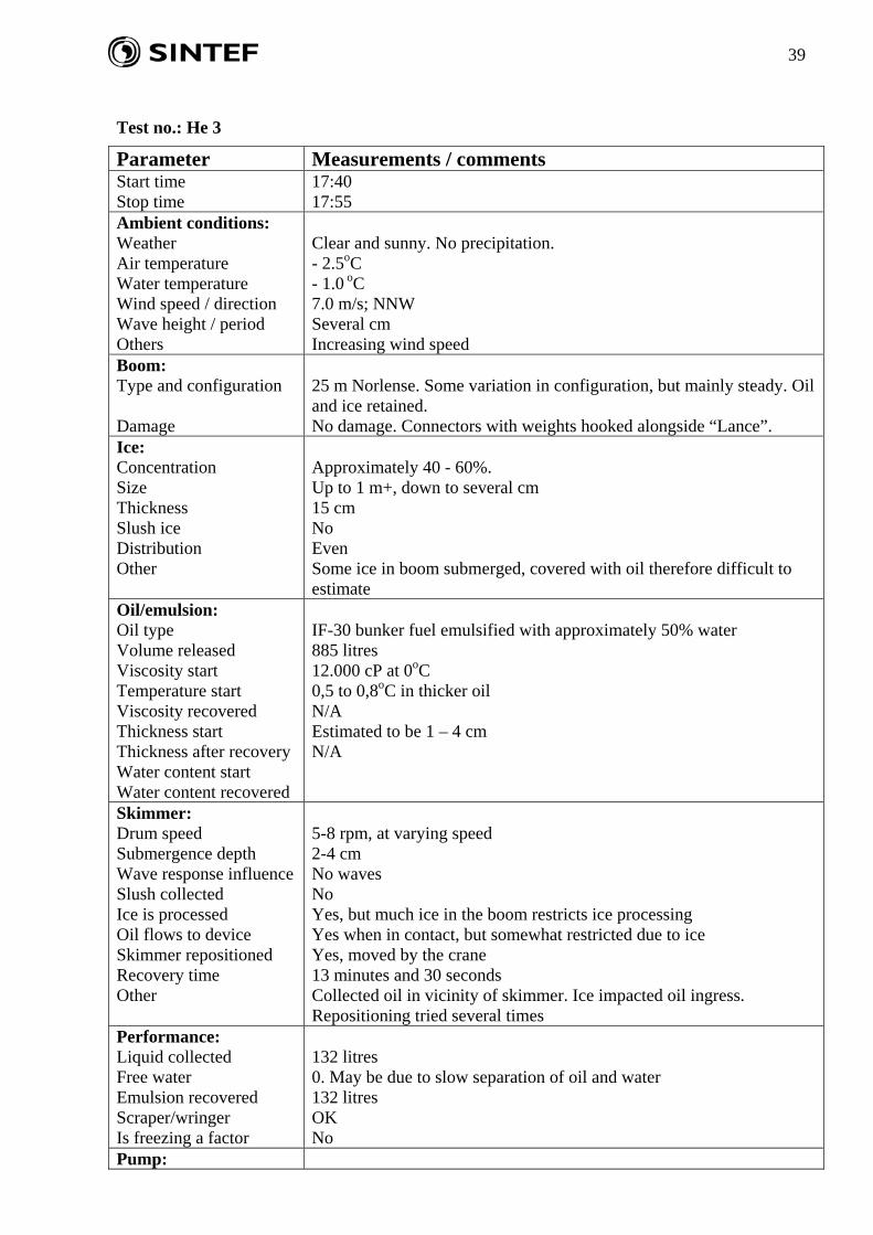
39
Test no.: He 3
Parameter Measurements / comments Start time Stop time
17:40 17:55
Ambient conditions: Weather Air temperature Water temperature Wind speed / direction Wave height / period Others
Clear and sunny. No precipitation. - 2.5oC - 1.0 oC 7.0 m/s; NNW Several cm Increasing wind speed
Boom: Type and configuration Damage
25 m Norlense. Some variation in configuration, but mainly steady. Oil and ice retained. No damage. Connectors with weights hooked alongside “Lance”.
Ice: Concentration Size Thickness Slush ice Distribution Other
Approximately 40 - 60%. Up to 1 m+, down to several cm 15 cm No Even Some ice in boom submerged, covered with oil therefore difficult to estimate
Oil/emulsion: Oil type Volume released Viscosity start Temperature start Viscosity recovered Thickness start Thickness after recovery Water content start Water content recovered
IF-30 bunker fuel emulsified with approximately 50% water 885 litres 12.000 cP at 0oC 0,5 to 0,8oC in thicker oil N/A Estimated to be 1 – 4 cm N/A
Skimmer: Drum speed Submergence depth Wave response influence Slush collected Ice is processed Oil flows to device Skimmer repositioned Recovery time Other
5-8 rpm, at varying speed 2-4 cm No waves No Yes, but much ice in the boom restricts ice processing Yes when in contact, but somewhat restricted due to ice Yes, moved by the crane 13 minutes and 30 seconds Collected oil in vicinity of skimmer. Ice impacted oil ingress. Repositioning tried several times
Performance: Liquid collected Free water Emulsion recovered Scraper/wringer Is freezing a factor
132 litres 0. May be due to slow separation of oil and water 132 litres OK No
Pump:

40
Transfer Comments
OK Intermittent when sump full
Power pack: Hydraulic pressure Operation
OK.