Replication Mechanisms for Reference Datascg.unibe.ch/archive/projects/Kuer18a.pdf · Replication...
71
Replication Mechanisms for Reference Data Bachelor Thesis Tanja Leigh K¨ ury from Hofstetten-Fl¨ uh SO, Switzerland Philosophisch-naturwissenschaftliche Fakult¨ at der Universit¨ at Bern 18 March 2018 Prof. Dr. Oscar Nierstrasz Software Composition Group Institute of Computer Science University of Bern, Switzerland
Transcript of Replication Mechanisms for Reference Datascg.unibe.ch/archive/projects/Kuer18a.pdf · Replication...

Replication Mechanisms forReference Data
Bachelor Thesis
Tanja Leigh Kuryfrom
Hofstetten-Fluh SO, Switzerland
Philosophisch-naturwissenschaftliche Fakultatder Universitat Bern
18 March 2018
Prof. Dr. Oscar Nierstrasz
Software Composition GroupInstitute of Computer Science
University of Bern, Switzerland

Abstract
Growing numbers of applications interacting with each other facilitate theneed to share data between various systems. The interconnected applicationsused to manage immigrant and asylee need the same reference data inorder to consistently fulfil their purpose. This thesis examines the usedreplication mechanism requiring direct database access and proposes animproved design. By analysing the situation and validating alternativereplication mechanisms that adhere to the defined architectural standards itwas possible to propose two realistic approaches, one of which is alreadyin development. A proof of concept using a message oriented middlewareshowed that extending the architecture concept might even be more future-oriented.
i

Acknowledgement
I would like to offer my special thanks to Prof. Dr. Oscar Nierstrasz formaking it possible to realise this project as bachelor thesis in the SoftwareComposition Group of the University of Bern.
Also, I want to thank the Informatik Service Center ISC-EJPD for pro-viding we with the work place and requirements, as well as advice andfeedback.
I am particularly grateful for the guidance and support given by DavidKlaper and Rolf Scherer through the whole project.
Adrian Burki and Didier Spicher provided me with very valuable insightthat facilitated the definition of requirements and thus the developmentprocess.
At last I want to thank Lars Vogtlin and everyone else that supported andencouraged me.
ii
Contents
1 Introduction 1
2 Background 22.1 Central Migration Information System . . . . . . . . . . . . . . . . . . 32.2 ZEMIS Reference Data Management . . . . . . . . . . . . . . . . . . . 32.3 Initial State . . . . . . . . . . . . . . . . . . . . . . . . . . . . . . . . 3
2.3.1 Meta Data Concept . . . . . . . . . . . . . . . . . . . . . . . . 42.3.2 Replication Mechanism . . . . . . . . . . . . . . . . . . . . . 5
2.4 SOAP Web Service . . . . . . . . . . . . . . . . . . . . . . . . . . . . 62.4.1 eXtensible Markup Language Schema Definition . . . . . . . . 72.4.2 SOAP Web Service Description . . . . . . . . . . . . . . . . . 7
2.5 SoapUI . . . . . . . . . . . . . . . . . . . . . . . . . . . . . . . . . . 82.6 JMeter . . . . . . . . . . . . . . . . . . . . . . . . . . . . . . . . . . . 82.7 Java Persistence API . . . . . . . . . . . . . . . . . . . . . . . . . . . 9
3 Methodology 103.1 Adapting the Meta Data Model . . . . . . . . . . . . . . . . . . . . . . 11
3.1.1 Improving the Versioning System . . . . . . . . . . . . . . . . 113.2 Replication Variants . . . . . . . . . . . . . . . . . . . . . . . . . . . . 11
3.2.1 Variant 1: Push Architecture . . . . . . . . . . . . . . . . . . . 123.2.2 Variant 2: Direct Pull Architecture . . . . . . . . . . . . . . . . 133.2.3 Variant 3: Pull Architecture with Caching . . . . . . . . . . . . 143.2.4 Variant 4: Push Notify to Pull Architecture . . . . . . . . . . . 14
3.3 Stakeholder Interviews . . . . . . . . . . . . . . . . . . . . . . . . . . 163.4 Evaluation of Variants . . . . . . . . . . . . . . . . . . . . . . . . . . . 17
3.4.1 Evaluation Variant 1: Push Architecture . . . . . . . . . . . . . 173.4.2 Evaluation Variant 2: Direct Pull Architecture . . . . . . . . . . 173.4.3 Evaluation Variant 3: Pull Architecture with Caching . . . . . . 183.4.4 Evaluation Variant 4: Push Notify to Pull Architecture . . . . . 193.4.5 Conclusion . . . . . . . . . . . . . . . . . . . . . . . . . . . . 19
iii
CONTENTS iv
4 Validation 204.1 Designing the Prototype Structures . . . . . . . . . . . . . . . . . . . . 20
4.1.1 Pull Architecture with Caching . . . . . . . . . . . . . . . . . . 214.1.1.1 Web Service Description . . . . . . . . . . . . . . . 214.1.1.2 XML Data Structures . . . . . . . . . . . . . . . . . 23
4.1.2 Push Architecture . . . . . . . . . . . . . . . . . . . . . . . . . 254.1.2.1 Web Service Description . . . . . . . . . . . . . . . 254.1.2.2 XML Data Structures . . . . . . . . . . . . . . . . . 26
4.1.3 Direct Pull Architecture . . . . . . . . . . . . . . . . . . . . . 274.2 Building the Prototypes . . . . . . . . . . . . . . . . . . . . . . . . . . 27
4.2.1 Building the Prototype for Pull Architecture with Caching . . . 274.2.1.1 Creating the Java Persistence API (JPA) Entities . . . 274.2.1.2 Implementing the Methods . . . . . . . . . . . . . . 29
4.3 Findings from the Prototypes . . . . . . . . . . . . . . . . . . . . . . . 314.3.1 Testing . . . . . . . . . . . . . . . . . . . . . . . . . . . . . . 314.3.2 Problems . . . . . . . . . . . . . . . . . . . . . . . . . . . . . 31
5 Conclusion and Future Work 345.1 Conclusions . . . . . . . . . . . . . . . . . . . . . . . . . . . . . . . . 345.2 Future Work . . . . . . . . . . . . . . . . . . . . . . . . . . . . . . . . 35
5.2.1 Management of Reference Data trough Clients . . . . . . . . . 355.2.2 Extended Functionality . . . . . . . . . . . . . . . . . . . . . . 35
5.3 Developments of Needs and Circumstances . . . . . . . . . . . . . . . 35
A Anleitung zu wissenschaftlichen Arbeiten 36A.1 Background . . . . . . . . . . . . . . . . . . . . . . . . . . . . . . . . 36
A.1.1 Basic Concepts . . . . . . . . . . . . . . . . . . . . . . . . . . 37A.2 Developing the Prototype . . . . . . . . . . . . . . . . . . . . . . . . . 38
A.2.1 Preparation . . . . . . . . . . . . . . . . . . . . . . . . . . . . 38A.2.2 Implementing the Prototype . . . . . . . . . . . . . . . . . . . 40
A.2.2.1 Producer . . . . . . . . . . . . . . . . . . . . . . . . 40A.2.2.2 Consumer . . . . . . . . . . . . . . . . . . . . . . . 41
A.2.3 Conclusion . . . . . . . . . . . . . . . . . . . . . . . . . . . . 42
B XML Schema Definition 43B.0.1 Pull Architecture with Caching . . . . . . . . . . . . . . . . . . 43B.0.2 Push Architecture . . . . . . . . . . . . . . . . . . . . . . . . . 52
C Declaration 53

CONTENTS v
D Interviews 54D.1 Questions for Adrian Burki . . . . . . . . . . . . . . . . . . . . . . . . 54D.2 Questions and Answers: Didier Spicher . . . . . . . . . . . . . . . . . 57

List of Figures
2.1 Inital State . . . . . . . . . . . . . . . . . . . . . . . . . . . . . . . . . 4
3.1 Push Architecture . . . . . . . . . . . . . . . . . . . . . . . . . . . . . 123.2 Direct Pull Architecture . . . . . . . . . . . . . . . . . . . . . . . . . . 133.3 Pull Architecture with Caching . . . . . . . . . . . . . . . . . . . . . . 143.4 Push Notify to Pull Architecture . . . . . . . . . . . . . . . . . . . . . 15
A.1 AMQP concept . . . . . . . . . . . . . . . . . . . . . . . . . . . . . . 37A.2 RabbitMQ server . . . . . . . . . . . . . . . . . . . . . . . . . . . . . 38A.3 Routing setup . . . . . . . . . . . . . . . . . . . . . . . . . . . . . . . 39
vi

Listings
1 Basic example for a SOAP web service description . . . . . . . . . . . 82 Methods used for the Pull Architecture with Caching . . . . . . . . . . 213 Web service interface defined as group of operations . . . . . . . . . . 224 Publishing the web service . . . . . . . . . . . . . . . . . . . . . . . . 225 XML file the client MIDES might use to pull all its entities . . . . . . . 236 XML file the client MIDES might use to pull two entities . . . . . . . . 237 Example of a response eXtensible Markup Language (XML) file . . . . 248 Methods used for the Push Architecture . . . . . . . . . . . . . . . . . 259 Web service interface defined as group of operations . . . . . . . . . . 2610 Publishing the web service . . . . . . . . . . . . . . . . . . . . . . . . 2611 Definition of the refDataRequestType . . . . . . . . . . . . . . . . . . 2612 Annotating an entity . . . . . . . . . . . . . . . . . . . . . . . . . . . 2813 Annotating a column . . . . . . . . . . . . . . . . . . . . . . . . . . . 2814 Defining named queries . . . . . . . . . . . . . . . . . . . . . . . . . . 2815 Declaring the one-to-many relation . . . . . . . . . . . . . . . . . . . . 2916 Declaring the many-to-one relation . . . . . . . . . . . . . . . . . . . . 2917 Using the namedQuery to get the client from the database . . . . . . . . 3018 Create response and add its entities . . . . . . . . . . . . . . . . . . . . 3019 First version of the file containing reference data . . . . . . . . . . . . 3220 Second version of the file containing reference data . . . . . . . . . . . 3221 Basics for setting up producer or consumer . . . . . . . . . . . . . . . 4022 generalRefDataRequest as defined in the XML Schema Definition (XSD) 4323 allMyEntitiesRefDataRequest request as defined in the XSD . . . . . . 4424 Example of a pull request . . . . . . . . . . . . . . . . . . . . . . . . . 4525 multipleEntitiesRefDataRequest request as defined in the XSD . . . . . 4526 Example of a pull request for several entities . . . . . . . . . . . . . . . 4627 modifiedOrNew Type defined in the XSD . . . . . . . . . . . . . . . . 4628 Definition of the refDataResponseType . . . . . . . . . . . . . . . . . . 4729 Definition of the entityType . . . . . . . . . . . . . . . . . . . . . . . . 4730 tableType and entityPartType element definition . . . . . . . . . . . . . 4831 columnType and dataTypeType element definition . . . . . . . . . . . . 4932 rowType element definition . . . . . . . . . . . . . . . . . . . . . . . . 50
vii

LISTINGS viii
33 Example of a response XML file . . . . . . . . . . . . . . . . . . . . . 5134 Definition of the refDataRequestType . . . . . . . . . . . . . . . . . . 52

Acronyms
AMQP Advanced Message Queuing Protocol
API Application Programming Interface
EJPD Federal Department of Justice and Police
GUI Graphical User Interface
ISC IT Service Centre of the Federal Department of Justice and Police
JAX-WS Java API for XML Web Services
JPA Java Persistence API
JPQL Java Persistence Query Language
JSR 220 Enterprise JavaBeans 3.0 Specification
MIDES ”Informationssystem der Empfangs- und Verfahrenszentren und der Unterkunftean den Flughafen”
ORM Object-Relational Mapping
POJO Plain Old Java Object
REST Representational State Transfer
SEM State Secretary for Migration
SOAP SOAP Version 1.2
URI Unique Resource Identifier
W3C World Wide Web Consortium
WSD Web Service Description
WSDL Web Service Description Language
ix

LISTINGS x
XML eXtensible Markup Language
XSD XML Schema Definition
ZEMIS Central Migration Information System
ZEMIS Ref ZEMIS Reference Data Management

1Introduction
The Central Migration Information System (ZEMIS) [18] is an application to managedata about immigrants and asylees. Multiple applications with their own data thatreferences ZEMIS data are related to it. To guarantee a consistent interpretation of thedata, secondary information, such as available countries, cantons, or permits is necessary.This data is called reference data and managed trough a separate application, ZEMISReference Data Management (ZEMIS Ref), with a separate database. The two mainpurposes of reference data are displaying translated texts and controlling applicationbehaviour. Due to occasional changes it needs to be replicated into the databases of theseapplications needing certain reference data to interpret ZEMIS data.
The current replication mechanism is based on a direct database access from theapplication ZEMIS Ref to the target application databases. This leads to a tight couplingand may also be a security issue. The target databases need to follow a prescribed datascheme and cannot change internally. For additional applications outside the scope ofproject ZEMIS that will be produced in the near future as part of an e-Governmentprogram, this replication mechanism cannot be used due to the required direct databaseaccess.
Due to political and technical changes the current ZEMIS Ref application will bereplaced. Its outdated web technology presents security risks and needs to be replaced.Also, a significant part of the business logic has been integrated into the web layer, hencea rewrite of most parts of the system is required.
This project focused on exploring different options for replacing the inadequatereplication mechanism. We came up with several potential approaches and explored theirfeasibility with stakeholders and through prototyping.
1

2Background
ZEMIS Ref, the application hosting reference data required to interpret data providedby ZEMIS, currently has writing permissions to the databases of all those applicationsneeding this data. These clients thus are tightly coupled to ZEMIS Ref as they cannotstore the data in a way that suits their architecture but have to use the prescribed datascheme. Anytime a change of the scheme occurs they have to adapt but they cannotthemselves change internally.
In the future applications outside the ZEMIS landscape will be developed and needaccess to reference data. Due to the required direct database access with hard codedproperties a ZEMIS release is required to add a new client. The releases are planned foreach entire year in advance, so there is simply no room for considering the schedules ofthe new clients when planning. Furthermore, it may be a security issue to have directdatabase access, as some of these application handle very sensitive data.
In this chapter, we provide the background information required to understand thepurpose and proceedings of this project along with a short introduction of the technologiesused.
2

CHAPTER 2. BACKGROUND 3
2.1 Central Migration Information SystemZEMIS is a web application used to manage immigrant and asylee data. Several appli-cations communicate with it over interfaces, like the application ”Informationssystemder Empfangs- und Verfahrenszentren und der Unterkunfte an den Flughafen” (MIDES)[9] that is used to manage asylum seekers in reception and procedure centres. ZEMISis the central system, mainly used for management of person data, while the relatedapplications extend its functionality or need its data. The refugee aid centres regularlyget refugee data in order to be able to aid them. Secondary information, necessaryto guarantee a consistent interpretation of the data, is managed in another application,ZEMIS Ref.
2.2 ZEMIS Reference Data ManagementReference data is business data that changes only rarely and is used to control applicationbehaviour, display values and interpret ZEMIS data. The web application ZEMIS Refmanages this data. Its database structure is quite complex, thus implemented with ameta data concept. The initial state concerning the replication of reference data to thetarget databases, as well as the meta data concept implemented to be able to do so shouldbe understood before trying to decouple these applications with usage of a differentarchitectural concept and technology. The next section conveys the basic design andfurther sections focus on the technologies used.
2.3 Initial StateZEMIS Ref keeps track not only of values currently active, but also keeps some additionalinformation about how data was edited. Only the currently valid values are of interest forthe client application, not old values.
Whenever valid data changes ZEMIS Ref exports these changes and writes theminto all target databases needing the respective data, as shown in figure 2.1, with socalled replications. To be able to do so information about the database connections andreplication jobs are kept, as well as their success or failure. See section 2.3.1 Meta DataConcept.

CHAPTER 2. BACKGROUND 4
Figure 2.1: Conceptual figure of Inital State showing only relevant interactions.
When a data change is made, the change is reflected by making a new entry with thesame key and marking the previous entry as old. This provides a crude way of versioningor historisation. There is no possibility to find out which value was active at a particulartime, as old entries can be reactivated. Thus, it is not possible to trace the history ofpossible values. The possibility to display inactivated records is currently given and veryimportant. For example you still need to see the country in which a person was born,even if it does not exist anymore (like Yugoslavia), but you should not be able to select itfor a newborn child.
The meta model defines the data scheme which also the client applications need tofollow. This tightly couples ZEMIS Ref and its clients. Moreover, to add a new client,all required information, including database authorisation information, has to be added,thus requiring a ZEMIS release.
2.3.1 Meta Data ConceptTo describe the actual ZEMIS Ref tables a meta data model is used. This allows creatingnew tables without having to change the application code. This model describes theentities that consist of one or several tables with records belonging together as well astheir relations.
The entities are normally built from one table holding the business information, calledTARP entityname bs, and one holding the text values that contain text in multiplelanguages to support internationalisation, called TARP entityname tx. An entitycan be a canton, country, authorisation code or other data not changing often. The metamodel describes these entities, like name, type, characteristics and so on.
CHAPTER 2. BACKGROUND 5
Additionally there are relational tables used to show relations between entities, withTARP relationname r as name. These are only used for defining valid combinations,thus only used to implement logic.
The meta data model is also used to manage access. Each entity has one of the targetsystems as data owner or is commonly owned. A user of the application can manage thedata in a not normalised way, meaning he does not see each table of an entity, but all dataof the entity at once, which is referenced as joined view. The tables are described by themeta model tables named as TARM NAME.
The meta model consists of the following tables:
• TARM ENTITAET: ID, data owner and name of the joined view (shown in theGUI) for each entity
• TARM ENTITAETTEXT: Texts that shall be shown in the GUI in German, Frenchand Italian, mapped to an entity ID.
• TARM VIEW: Matches entities, meaning the tables it consists of, to views to showin the GUI
• TARM FELD: Meta information for fields used for each entity, e.g. format id, nameand position to show in the GUI, description, length and so on
• TARM FORMAT: format id and name to describe the format of the fields
• TARM KONTROLLE: Same as TARM FELD but for the control fields
• TARM REPL SUBSCR: Maps clients to entities by using their IDs. This defines towhich client databases ZEMIS Ref has to replicate what entities
• TARM REPL ENTITAET: Information about success or failure for each replicatedentity for each client, containing foreign key to the replication job
• TARM REPL JOB: Information concerning each replication job (containing multi-ple replicated records)
2.3.2 Replication MechanismWhenever ZEMIS Ref exports reference data and imports it into a target system bywriting into its database, this is called a replication. By using the web application theuser can configure when replication jobs should be executed.
Mass replication, containing all changes of valid records, are currently configured tobe executed during the night, while immediate replications of single or multiple recordsare initialised manually. The replication job is then started immediately for all selectedrecords, independent of the date provided by the valid from field. This is only takeninto account in a mass replication job.
CHAPTER 2. BACKGROUND 6
If the user does not need the replication to take place immediately, he can simplymutate or create the entry, set the valid from date and let it be mass replicated duringeach night corresponding to the set date. Success or failure for each replication job arerecorded.
Normally it is known in advance when a change is due and the records are preparedwell in advance and replicated during the night. Exceptions happen occasionally, forexample to make it possible to redo something that is not any more possible due toinactivated values, but that was modified wrongly and must be corrected, like for exampleredo a permit for a person from Yugoslawia. So sometimes values must be reactivatedonly for a short time and then be deactivated again, which is the reason for the possibilityto manually initialise replications.
2.4 SOAP Web ServiceA different approach to transmit data, i.e., replicate data between applications thanusing direct database access is building a web service. Web services are softwaresystems supporting interoperable machine-to-machine communication by offering aninterface over which other systems may interact in a prescribed manner. A Web ServiceDescription (WSD) describes the interface in a format machines can process; for a SOAPWeb Service this description is written in Web Service Description Language (WSDL).
SOAP Version 1.2 (SOAP), recommended by the World Wide Web Consortium(W3C), is:
”[...] a lightweight protocol intended for exchanging structured informationin a decentralized, distributed environment” [8].
It basically defines an extensible messaging framework with XML technologies, inde-pendent of implementation or underlying protocols.
While there are several ways to implement web services, for communication withexternal applications the IT Service Centre of the Federal Department of Justice andPolice (ISC) does so by following SOAP protocol.

CHAPTER 2. BACKGROUND 7
The providing entity of the web service, a person or organisation, is the owner onwho’s behalf the web service provides functionality, while the requesting entity is theperson or organisation using this service. Communication takes place by means ofXML-Messages, using a clearly defined XSD. Communication is normally started bythe requesting entity, but exceptions are possible.
2.4.1 eXtensible Markup Language Schema DefinitionIn a SOAP web service XML-messages are used to exchange data. XML is a markuplanguage defining a set of rules for encoding documents that are human-readable aswell as machine-readable. The structure of an XML document has to follow a definedschema to be suitable as message format for machine-to-machine communication. Anapproach to do so is by usage of XSD that is also encoded in XML. It basically defines avocabulary to be used by the providing and requesting entities of the web service andensures the XML conforms to what is expected.
The XSD is referenced in the XML document through a namespace, the name ofit being the Unique Resource Identifier (URI) for the schema. The XML documentcan then be validated against the XSD to see whether it follows its rules or not. Inthe same manner a schema definition can include other schema definitions; in that wayvocabularies can be reused.
2.4.2 SOAP Web Service DescriptionA WSD describes a web service by indicating how potential clients should interact withit. It basically works as a contract between the providing entity and the requesting entity.In that way the client knows what the web service offers and how to make use of it,while the provider only has to answer valid requests and make sure to answer with validresponses. The WSD specifies the web service location and the methods by using thebasic elements in this structure, encoded in XML. Listing 1 shows the structure of aSOAP web service description.

CHAPTER 2. BACKGROUND 8
1 <definitions>2 <types>3 XML Schema type definitions4 </types>5 <message>\label{code:message}6 Definition of an abstract message that can serve7 as input or output of an operation. It can consist8 of one or multiple part elements9 </message>
10 <message>11 ...12 </message>13 ...14 <portType>15 Definiton of operations e.g. the interface16 </portType>17 <binding>18 Definition of concrete details for each operation19 </binding>20 </definitions>
Listing 1: Basic example for a SOAP web service description
2.5 SoapUISoapUI is an open source web service testing tool, offering SOAP Web Service andRepresentational State Transfer (REST) Application Programming Interface (API) func-tional testing.[15]
SOAP Web Services can be functionally tested by providing the server address andweb service description defined in a WSDL and letting SoapUI generate request messagesfollowing the description, optionally with adaptable sample values fulfilling the schemadefined in the XSD. A request message can then be sent to the web service, which sendsback a response message that can be validated against expectations. The XML files arevalidated against the according schema and errors are indicated, so that the user can seethem easily.
2.6 JMeterWhen building a SOAP Web Service, not only functionality is a factor to test, but alsoperformance. Even though SoapUI offers functions to do so, JMeter is better suited forload and performance testing, as it is an open source software especially designed forthat purpose.[5]

CHAPTER 2. BACKGROUND 9
JMeter basically works like a form letter. To load test a SOAP Web Service, youcreate a Test Plan in which you define how many users shall be mocked, represented asthreads, and provide the request template and where to get the variable data from. Also,server location is needed, so it knows where to send the requests to. It can detect errors,but as it is given no schema definition or WSD, there is no way for it to detect whetherthe responses are conform to the schema or not. It offers several summary reports wherestatistics about the response times, size of messages and so on are shown.
2.7 Java Persistence APIThe Java Persistence API [6], already used in ZEMIS Ref, provides a solution to per-sistently save Plain Old Java Object (POJO) to a relational database by standardisingObject-Relational Mapping (ORM). It was developed as part of Enterprise JavaBeans3.0 Specification (JSR 220), but can also be used outside the Java EE platform.
A POJO simply needs to be annotated to describe the characteristics of the entity itrepresents and the resources it needs. The mappings, entity relationships and deploy-time instructions are also set by annotations. This approach simplifies developing javaapplications using relational databases. Moreover, by usage of the enhanced querylanguage Java Persistence Query Language (JPQL) it is possible to be independent ofthe database technology, as it works on the JPA entity level and thus is automaticallymapped to the required query language.

3Methodology
While the initial idea was to focus on the meta model, it became evident that the morepressing need for change was in the replication mechanism. Thus, we focused onevaluating alternatives to this complex core piece of the application.
In order for the various stakeholders to be able to work with the solution, we first hadto evaluate their needs, then find out which are most important for them.
Four different variants to replace the replication mechanism that in our opinion wereable to fulfil basically all needs were established and further investigated. Interviews withthe stakeholders made sure to get feedback on these variants. As the solution shall beused in the ISC, we also had to make sure they follow their rules, defined in the relevantsoftware architecture standards.
One additional variant using a messaging service, which is currently not a standardcomponent in the ISC reference architecture, was further investigated, to show potentialimprovements by using such a framework in the next iteration of the architecturalstandards. It is described in Appendix A ”Anleitung zu wissenschaftlichen Arbeiten”.
10
CHAPTER 3. METHODOLOGY 11
3.1 Adapting the Meta Data ModelThe meta data model depends on the data replication mechanism used, as this mechanisminfluences different options for versioning and replication tracking. As versioning andrepresentation in the application Graphical User Interface (GUI) are the core issuessolved by the meta data model it must be adapted according to the new mechanism used.
3.1.1 Improving the Versioning SystemWhen a change is made, the change is reflected by making a new record with the samekey and marking the previous record as old using the state cd field. This providesa crude way of versioning or historisation. Essentially, for one entity multiple recordsare kept, but only one is marked as the currently valid entity for the given key.
By introducing a new field containing the last mutation date of the state cd field acomplete historisation could be achieved. It would then be possible to see which recordwas in use at which date and time. Reactivation of a record not valid any more, as iscurrently possible, should then be prevented. Instead a new record should be produced toensure data consistency. This isolated change was not implemented in a prototype.
3.2 Replication VariantsThe approaches described in this section were defined at project start. They were laterevaluated and adapted. Special focus lied on ensuring data consistency and synchronicity.These are very important aspects, as the reference data is not only used to represent data,but in some cases also to control application behaviour.
As the applications need to ensure that only combinations of certain values accordingto current law are possible, it is very important that changes of these combinations areconsistent in all applications using reference data. For instance, valid permit types andtheir corresponding valid permit code combinations are such legally binding information.
Furthermore sometimes business tasks are started in one application and terminatedin an other. If these applications had concurrently differing reference data, this couldlead to synchronisation problems and data conflicts and thus to errors in the applications.So synchronicity must be ensured over all related applications.
For each variant a figure showing relevant data flow provides a conceptual overview,while the according architecture is described.

CHAPTER 3. METHODOLOGY 12
3.2.1 Variant 1: Push ArchitectureA possibility to keep the push model is using a web service client model, as shown infigure 3.1. ZEMIS Ref sends a request containing reference data, the clients acknowledgethe reception. Thus, the direct access to the target databases is no longer required, butthe client systems need to provide an implementation of a web service interface wedefine. This means more implementation work, but less coupling between the clients andZEMIS Ref.
Figure 3.1: Conceptual figure of Push Architecture
Clients get the data and can handle it as they need, so they are free to change. It alsoensures that there are no issues concerning synchronisation, as the target databases arealways up to date if no failures occur. Also, future applications can be added easily to adynamic subscriber list that replaces the current static subscriber list (see 2.3.1).

CHAPTER 3. METHODOLOGY 13
To ensure data synchronicity a two-phase commit not shown in the figure can beused as follows: ZEMIS Ref sends a notification that includes information about the datachange, clients pull the data and vote for or against committing, depending on whetherthey were able to import it into their database. ZEMIS Ref then notifies the clients aboutthe result. They then either commit (if all voted for committing) or abort (if not). If oneof the clients is unavailable or encounters problems, this approach ensures that the datais the same in all client systems. An unanimous commitment may need several attempts.
3.2.2 Variant 2: Direct Pull ArchitectureIn this approach the target systems do not have their own databases for the reference data.Each time they need such data they must request the single value via the web serviceprovided by ZEMIS Ref. The response then contains the requested data. You can seethis in figure 3.2.
Figure 3.2: Conceptual figure of Direct Pull Architecture
There is no direct database access and the data is up to date all the time so there areno synchronisation problems. It gets problematic when the web service is offline or hasother disturbances that might affect the performance. The client systems depend heavilyon the web service and cannot be used when ZEMIS Ref is not working properly, somost likely a backup solution must be developed. Also, these requests must be fulfilledfast in order not to slow down the client systems. The web service needs to be able tofulfil many requests at once. There would be a high development effort needed regardingperformance attributes and potentially increases infrastructure cost because of the highfrequency, high performance requirements.
CHAPTER 3. METHODOLOGY 14
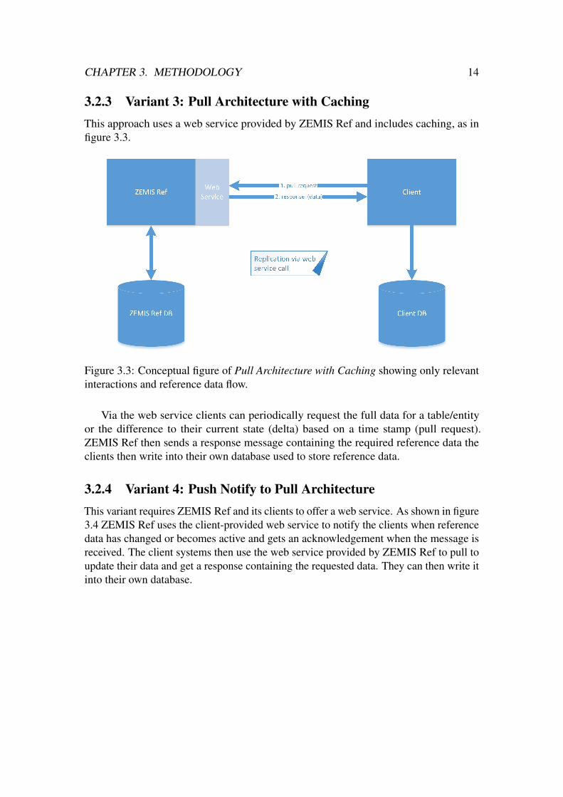
3.2.3 Variant 3: Pull Architecture with CachingThis approach uses a web service provided by ZEMIS Ref and includes caching, as infigure 3.3.
Figure 3.3: Conceptual figure of Pull Architecture with Caching showing only relevantinteractions and reference data flow.
Via the web service clients can periodically request the full data for a table/entityor the difference to their current state (delta) based on a time stamp (pull request).ZEMIS Ref then sends a response message containing the required reference data theclients then write into their own database used to store reference data.
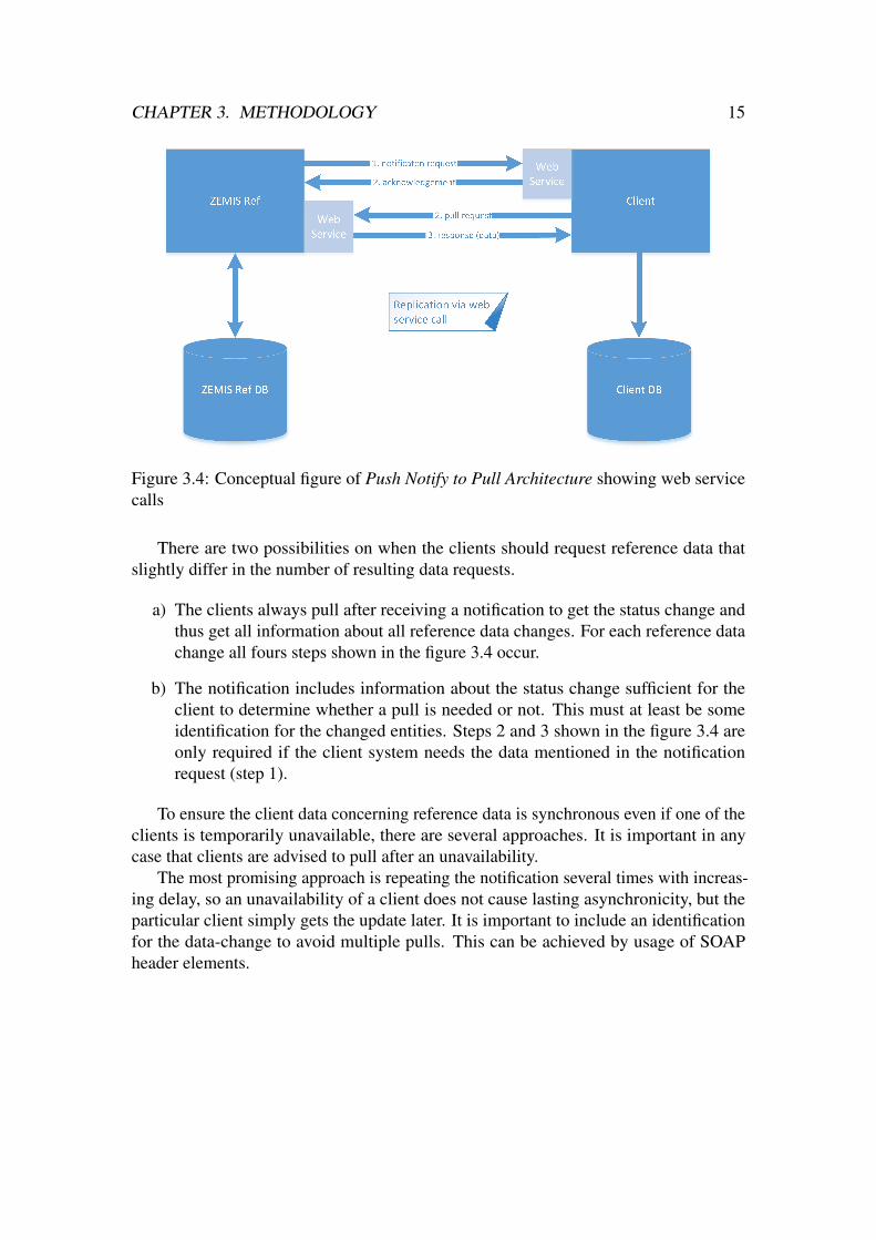
3.2.4 Variant 4: Push Notify to Pull ArchitectureThis variant requires ZEMIS Ref and its clients to offer a web service. As shown in figure3.4 ZEMIS Ref uses the client-provided web service to notify the clients when referencedata has changed or becomes active and gets an acknowledgement when the message isreceived. The client systems then use the web service provided by ZEMIS Ref to pull toupdate their data and get a response containing the requested data. They can then write itinto their own database.
CHAPTER 3. METHODOLOGY 15
Figure 3.4: Conceptual figure of Push Notify to Pull Architecture showing web servicecalls
There are two possibilities on when the clients should request reference data thatslightly differ in the number of resulting data requests.
a) The clients always pull after receiving a notification to get the status change andthus get all information about all reference data changes. For each reference datachange all fours steps shown in the figure 3.4 occur.
b) The notification includes information about the status change sufficient for theclient to determine whether a pull is needed or not. This must at least be someidentification for the changed entities. Steps 2 and 3 shown in the figure 3.4 areonly required if the client system needs the data mentioned in the notificationrequest (step 1).
To ensure the client data concerning reference data is synchronous even if one of theclients is temporarily unavailable, there are several approaches. It is important in anycase that clients are advised to pull after an unavailability.
The most promising approach is repeating the notification several times with increas-ing delay, so an unavailability of a client does not cause lasting asynchronicity, but theparticular client simply gets the update later. It is important to include an identificationfor the data-change to avoid multiple pulls. This can be achieved by usage of SOAPheader elements.

CHAPTER 3. METHODOLOGY 16
To reduce data load, the pulls should only request changed data, but full pulls (wholetables) must be possible also to support initial loads of the data for a new client. If forone table multiple records are modified and the clients get a notification for each of these,this would lead to a lot of notifications and pulls. To avoid this, ZEMIS Ref could wait adefined amount of time after a modification and only send a notification if no records ofthe same table are modified during this time. So with this delay only one notificationwould be sent for a sequence of updates on this table and only one pull made by eachclient.
3.3 Stakeholder InterviewsStakeholders are the product manager for ZEMIS Ref in State Secretary for Migra-tion (SEM) and the clients, for which we chose the lead developer of Adeya, a clientapplication in development in ISC, as representing person. We proposed them thesolution variants and tried to find out their requirements and what is important for them.
Didier Spicher, product manager of ZEMIS Ref, was only asked some general ques-tions, as the most adaptions would not affect the usage of ZEMIS Ref, but only thebehaviour. According to him it is important that there are no differences in the client datafor a longer time, but about half an hour would be no problem.
Also, the possibility to change a record and induce the replication immediately mustbe kept. Sometimes the support needs to correct mistakes made by the cantonal usersand thus has to do mutations that would normally not be possible due to the referencedata. So then they can change the according reference data, do the required mutations inthe target applications and then redo the reference data change. This is happening quiteoften, mainly during office hours, as a record in a state that is not allowed according tolaw cannot be kept in that state for a whole day.
Adrian Burki, lead developer of Adeya and Software Architect at ISC was providedwith information on the variants as in section 3.2 Replication Variants and asked toanswer some questions. He supported the evaluation of the technical consequences forthe different replication variants.

CHAPTER 3. METHODOLOGY 17
3.4 Evaluation of VariantsWith the Stakeholder feedbacks it was possible to already see positive and negativeaspects of the proposed variants and to further analyse and evaluate them. All variantsremove the direct database access and let the clients define their own scheme to be used,thus loosening the coupling.
3.4.1 Evaluation Variant 1: Push ArchitectureThis variant is closest to the initial state, as the exchange of the data is initialised byZEMIS Ref, just like replications.
A negative point is that the clients need to provide an implementation of a web serviceinterface we define. Thus, a new client has a higher initial development effort to connectto ZEMIS Ref. Also, this approach contradicts the ”pull over push” policy given by theISC.
Positive aspects are the robustness, that there is no heavy workload to be expectedand that it ensures consistency. As according to Didier Spicher data differences for abouthalf an hour are no problem the two phase commit is not needed. Also, Adrian Burki didnot see any reason to use a two phase commit.
As the meta model consists of tables to keep track of the replication jobs and entities,these could simply be adapted to keep track of the web service requests and their failureor success. Failure detection would be given, not successful requests could be repeatedeasily in half an hour and thus ensure consistency well enough.
Impact on the meta model
• Tarm repl subscr shall be dynamic subscriber list with the web service addresses
• Tarm repl clients must be kept
• Tarm repl job should be kept for traceability
• Tarm repl entity should be kept for traceability
3.4.2 Evaluation Variant 2: Direct Pull ArchitectureA direct pull architecture where records are pulled directly when required heavily dependson the providing entity of the web service, which in this approach is ZEMIS Ref. To beable to fulfil all requests during peak times when a heavy workload is to be expected fastenough to not slow down the clients several servers would be needed. Currently 2500calls/minute are to be expected in ZEMIS with a higher amount when considering theclient applications and also the new applications to be produced in the near future.

CHAPTER 3. METHODOLOGY 18
Although this variant seems to have some very good aspects, especially concerningconsistency and data synchronicity, we decided to not investigate it further due to theanticipated performance bottleneck.
Impact on the meta model
• Tarm repl subscr not needed
• Tarm repl job not needed
• Tarm repl entity not needed
3.4.3 Evaluation Variant 3: Pull Architecture with CachingThis variant, where ZEMIS Ref offers a web service and the clients pull periodically,adheres to the ”pull over push” policy the ISC follows. Also it is easy to add new clients,because only ZEMIS Ref needs to implement a web service interface, not the clients.
The only weakness, meaning differing data due to not clearly defined request times,is abated by regularly and often pulling clients and the statement that differences of abouthalf an hour are not expected to cause problems or errors. This required high rate of pullrequests might lead to many requests producing empty responses and thus unnecessarycommunication.
Also, it has the advantage that clients can pull deltas, meaning only the data differingfrom their current state, thus lessening performance requirements. This requires thatsome information to trace which client pulled when must be stored to be able to determinewhat data must be included in the response for a delta pull for each client application.
Impact on the meta model
• Tarm repl subscr not needed
• Tarm repl job not needed
• Tarm repl entity not needed
• New element: Probably an additional version control table or at least some fieldsfor version control are needed to be able to trace which client pulled when.

CHAPTER 3. METHODOLOGY 19
3.4.4 Evaluation Variant 4: Push Notify to Pull ArchitectureThis approach, with ZEMIS Ref and the client applications providing a web service,does not produce a lot of unnecessary communication, but ensures that pull requests areonly sent when in need of data. This is especially the case when including informationabout the data change in the notification and letting the clients determine whether theyneed to pull or not, as proposed for variant b. Variant a still requires the client to pullwhenever it receives a notification, thus results in more communication than variant b,but this is still way less than in the 3.2.3 pull architecture with caching.
Data synchronicity over all the clients and data consistency are maintained whenusing this approach. Also the coupling is loose, as ZEMIS Ref only needs to know theweb service locations of its clients, but does not have to keep track of pull request timesand status. The clients themselves need to ensure they get all data they need.
What contradicts this approach is that it requires ZEMIS Ref as well as the clientsto implement a web service client and interface and thus means a lot of implementationwork for the clients to initially connect to ZEMIS Ref.
As the pattern described in this variant resembles a ”publish-subscribe” pattern, wecame to the conclusion that a messaging service technology would suit better than theusage of web services, especially if half of the communicated information only consistsof notifications. As also Adrian Burki did propose the usage of a messaging servicetechnology, we followed that advice by prototyping an additional variant, see A Anleitungzu Wissenschaftlichen Arbeiten.
3.4.5 ConclusionThe evaluation of the variants showed us the differences between the possible dataexchange patterns. The stakeholder interviews further refined our understanding of theeffects each variant has. We expected a pull with caching architecture to be the mostlikely option due to the efficient decoupling and adherence to ISC standards, so westarted prototyping this variant to validate it. We also anticipated that the XSD requiredto implement the SOAP Web Service for the pull architecture with caching could beused as well for the push architecture with caching, as they must exchange the same datastructure, so this was the second variant to validate.
In addition, to show the potential of a proper publish subscribe architecture, weimplemented a very basic version using the message broker RabbitMQ. A description ofthis can be found in A ”Anleitung zu wissenschaftlichen Arbeiten”.
For the other variants we decided to not build a prototype as their disadvantagesshowed us they were very unlikely to be used in the ISC.

4Validation
After evaluating the different approaches to supersede the replication mechanism requir-ing direct database access we started implementing a prototype of our preferred variant,the pull architecture with caching (see 3.2.3). As similarities in the data exchange struc-ture, meaning the XML files, of this variant and the push architecture (see 3.2.1) wereobvious, the data structures could partially be used for both prototypes.
To build the prototypes we followed the contract first approach, which places themain focus on the XML structure of the messages to be sent rather than on the JAVAcode [7].
4.1 Designing the Prototype StructuresFirst of all we had to determine the offered services, as well as how and where clientsshould be able to claim them. These must be described in the WSD (see section 2.4SOAP Web Service Description). With these in mind, we started designing the prototypestructures by determining the XML data structure of the request and response files.Also, we produced the XSD so that the files pass the validation and the according WSDincluding these definitions. The basic structure and name conventions were given, as wewere provided with an example in use by the ISC.
20
CHAPTER 4. VALIDATION 21
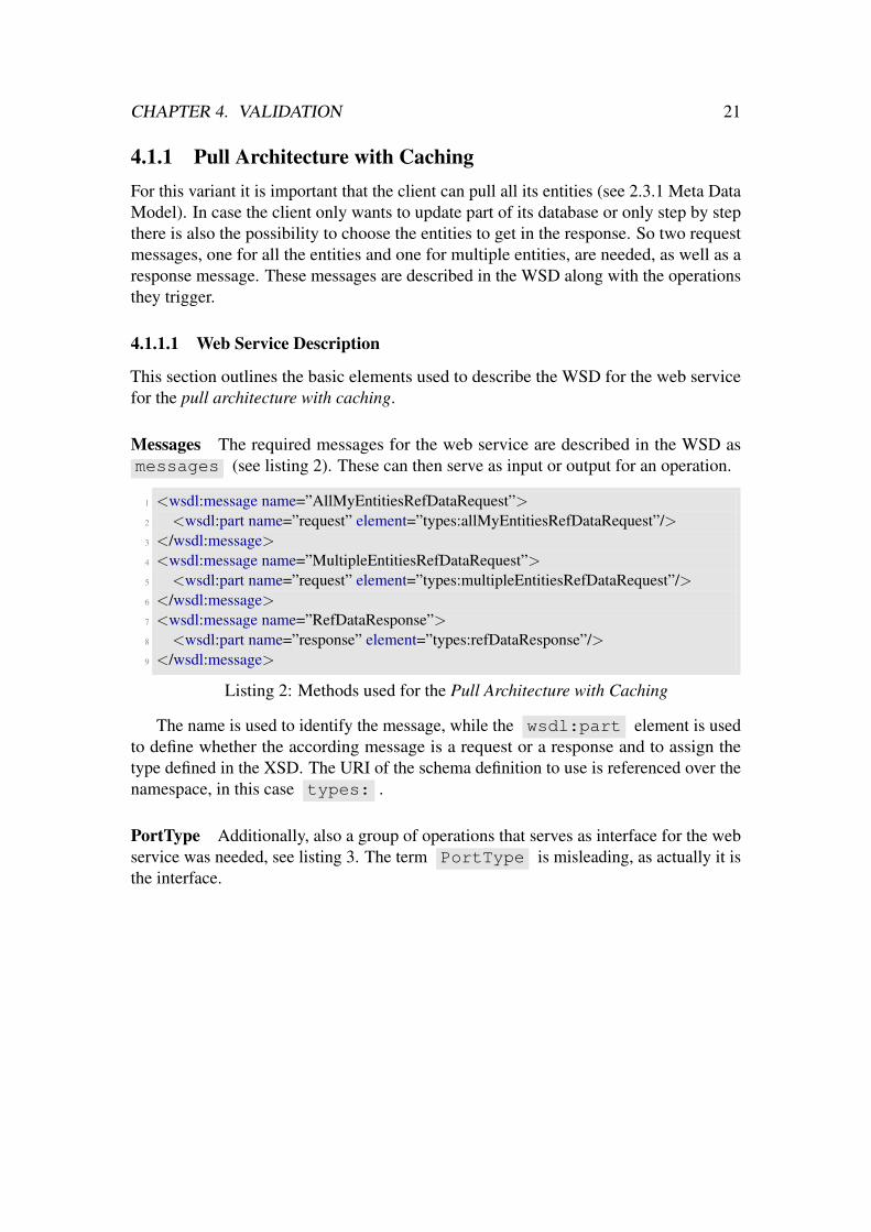
4.1.1 Pull Architecture with CachingFor this variant it is important that the client can pull all its entities (see 2.3.1 Meta DataModel). In case the client only wants to update part of its database or only step by stepthere is also the possibility to choose the entities to get in the response. So two requestmessages, one for all the entities and one for multiple entities, are needed, as well as aresponse message. These messages are described in the WSD along with the operationsthey trigger.
4.1.1.1 Web Service Description
This section outlines the basic elements used to describe the WSD for the web servicefor the pull architecture with caching.
Messages The required messages for the web service are described in the WSD asmessages (see listing 2). These can then serve as input or output for an operation.
1 <wsdl:message name=”AllMyEntitiesRefDataRequest”>2 <wsdl:part name=”request” element=”types:allMyEntitiesRefDataRequest”/>3 </wsdl:message>4 <wsdl:message name=”MultipleEntitiesRefDataRequest”>5 <wsdl:part name=”request” element=”types:multipleEntitiesRefDataRequest”/>6 </wsdl:message>7 <wsdl:message name=”RefDataResponse”>8 <wsdl:part name=”response” element=”types:refDataResponse”/>9 </wsdl:message>
Listing 2: Methods used for the Pull Architecture with Caching
The name is used to identify the message, while the wsdl:part element is usedto define whether the according message is a request or a response and to assign thetype defined in the XSD. The URI of the schema definition to use is referenced over thenamespace, in this case types: .
PortType Additionally, also a group of operations that serves as interface for the webservice was needed, see listing 3. The term PortType is misleading, as actually it isthe interface.

CHAPTER 4. VALIDATION 22
1 <wsdl:portType name=”ZemisRefDataPort”>2 <wsdl:operation name=”allMyEntities”>3 <wsdl:input message=”tns:AllMyEntitiesRefDataRequest”/>4 <wsdl:output message=”tns:RefDataResponse”/>5 <wsdl:fault name=”fault” message=”tns:FaultMessage”/>6 </wsdl:operation>7 <wsdl:operation name=”multipleEntities”>8 <wsdl:input message=”tns:MultipleEntitiesRefDataRequest”/>9 <wsdl:output message=”tns:RefDataResponse”/>
10 <wsdl:fault name=”fault” message=”tns:FaultMessage”/>11 </wsdl:operation>12 </wsdl:portType>
Listing 3: Web service interface defined as group of operations
These operations define one of the previously defined messages as input andanother one as output , as well as a message as fault in case a fault occurs.They basically map the requests to the according responses the web service provides andthus describe its interface and offered methods. When testing with SoapUI (see section2.5 SoapUI) the output message can be generated automatically with mock data whenprovided with the message that is defined as input message.
When using contract first approach [7] the portType and its operations provide theskeleton to be implemented, meaning Java interfaces including the methods.
Service To make the web service available for clients it must be published. This isdone by usage of the service element (listing 4).
1 <wsdl:service name=”ZemisRefDataService v1”>2 <wsdl:documentation>Web service definition for Zemis Ref Data Service, used3 to sync Ref Data between Zemis Ref and its Clients.</wsdl:documentation>4 <wsdl:port name=”ZemisRefDataPort” binding=”tns:ZemisRefDataBindingHTTP”>5 <soap:address location=”http://ejpd.admin.ch/sem/zemis/refdataservice”/>6 </wsdl:port>7 </wsdl:service>
Listing 4: Publishing the web service
Here not only the address location and port (meaning the interface)are described, but also a short documentation of what the service shall be usedfor.

CHAPTER 4. VALIDATION 23
4.1.1.2 XML Data Structures
Each message described in the WSD corresponds to one XML file. We first designedtheir structure that is shown here, then the schema definition that is explained in appendixB XML Schema Definition.
Request Messages The client may send a AllMyEntitiesRefDataRequestwith the structure as in listing 5 to request all its entities. Just the clientName isrequired. The startDate can be used to overwrite the date from which on to includedata changes and modifiedOrNew can be set to true to only get the entries modifiedor newly created since the provided start date or the stored date of the last pull.
1 <allMyEntitiesRefDataRequest xmlns=”http://ejpd.admin.ch/sem/zemis/refdataservice/types/v1”>
2 <clientName>MIDES</clientName>3 <startDate>2017−06−13T09:00:00</startDate>4 <modifiedOrNew>true</modifiedOrNew>5 </allMyEntitiesRefDataRequest>
Listing 5: XML file the client MIDES might use to pull all its entities
To request only some entities, a MultipleRefDataRequest in the structure asin listing 6 must be used. For each entity it is possible to get only the entries modified ornewly created.
1 <multipleEntitiesRefDataRequest xmlns=”http://ejpd.admin.ch/sem/zemis/refdataservice/types/v1”>
2 <clientName>MIDES</clientName>3 <startDate>2017−06−13T09:00:00</startDate>4 <requestedEntity>5 <entityName>Gemeinde</entityName>6 <modifiedOrNew>true</modifiedOrNew>7 </requestedEntity>8 <requestedEntity>9 <entityName>Adressdaten</entityName>
10 <modifiedOrNew>false</modifiedOrNew>11 </requestedEntity>12 </multipleEntitiesRefDataRequest>
Listing 6: XML file the client MIDES might use to pull two entities
Response Message The RefDataResponse message is a bit more complex thanthe Request messages. We had to redesign this part after testing, as the XML fileswere too big, see section B XML Schema Definition.

CHAPTER 4. VALIDATION 24
All requested entities are included in this file. The tables they consist of are sentseparately. For each table first the columns with their data type, which isimportant for the client applications, are sent with the name as, then the rows with thedata. To distinguish between the old, new and modified rows, the rows are grouped andmarked with the status attribute.
1 <ns4:refDataResponse xmlns:ns4=”http://...” xmlns=”http://...”>2 <ns4:refEntity joinedViewName=”VARP EMENDATION”>3 <ns4:table name=”VARP EMENDATION BS” entityPart=”business”>4 <ns4:columns>5 <ns4:col dataType=”ALPHA NUM”>KEYCD</ns4:col>6 <ns4:col dataType=”NUM”>TAGESGERICHT</ns4:col>7 ...8 </ns4:columns>9 <ns4:rows status=”old”>
10 <ns4:row index=”0”>11 <ns4:entry>asw</ns4:entry>12 <ns4:entry>357766</ns4:entry>13 ...14 </ns4:row>15 ...16 </ns4:rows>17 <ns4:rows status=”modified”>18 <ns4:row index=”0”>19 ...20 </ns4:row>21 ...22 </ns4:rows>23 <ns4:rows status=”new”>24 <ns4:row index=”0”>25 ...26 </ns4:row>27 </ns4:rows>28 ...29 </ns4:table>30 ...31 </ns4:refEntity>32 ...33 </ns4:refDataResponse>
Listing 7: Example of a response XML file

CHAPTER 4. VALIDATION 25
4.1.2 Push ArchitectureFor the push variant the workflow goes in the opposite direction, as shown in figure 3.1.The client does not have the freedom to choose, but changes are pushed at certain timesvia the offered web service and the client must be able to deal with them.
For the data structures, this means the previously defined response structure (seeB.0.1) can be reused, but must be defined as request, while the request structures cannotbe used, but a new response structure must be defined.
4.1.2.1 Web Service Description
The web service must be offered by the client applications. This section describes theparts that are not depending on a specific client application, but should be offered by allof them.
Messages The required messages for the web service are described in the WSD asmessages (see listing 8). These can then serve as an input or output for an operation.
1 <wsdl:message name=”RefDataRequest”>2 <wsdl:part name=”request” element=”types:refDataRequest”/>3 </wsdl:message>4 <wsdl:message name=”RefDataResponse”>5 <wsdl:part name=”response” element=”types:refDataResponse”/>6 </wsdl:message>7 <wsdl:message name=”FaultMessage”>8 <wsdl:part name=”parameter” element=”respfault:FaultInfo”/>9 </wsdl:message>
Listing 8: Methods used for the Push Architecture
The RefDataRequest message is used by ZEMIS Ref to send a messageincluding changed reference data. The client should then answer with a message of typeRefDataResponse . This is described in the portType .
CHAPTER 4. VALIDATION 26
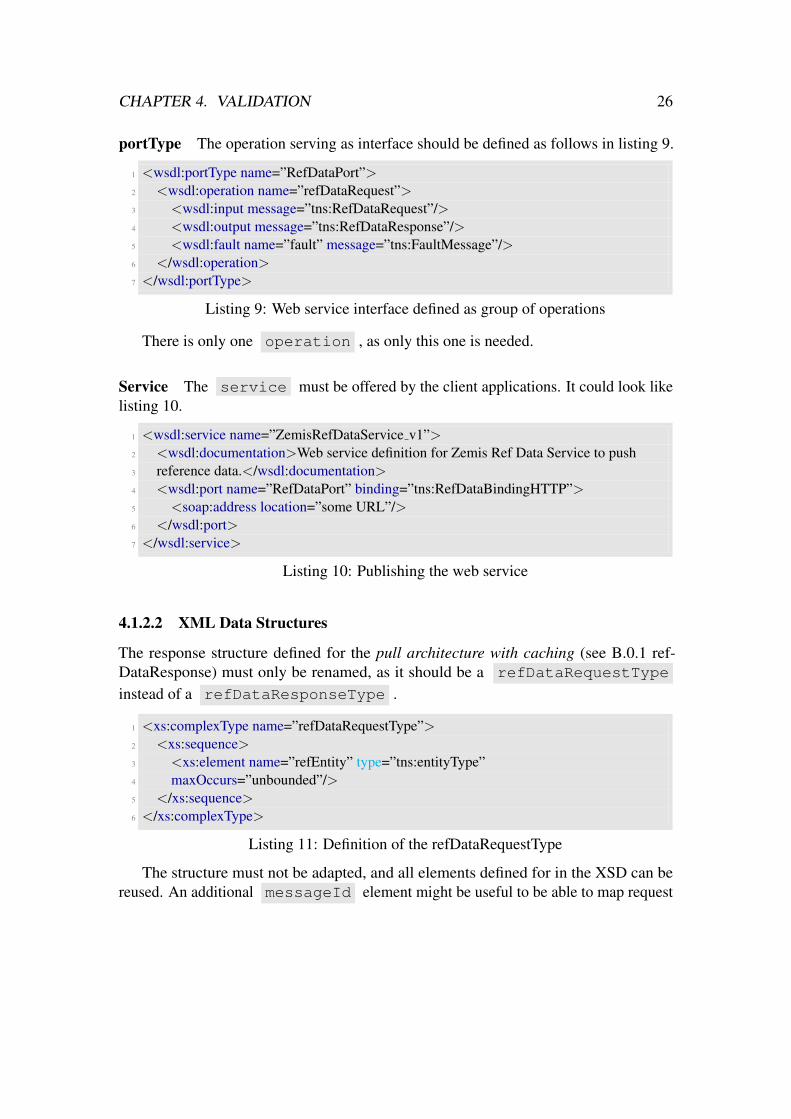
portType The operation serving as interface should be defined as follows in listing 9.
1 <wsdl:portType name=”RefDataPort”>2 <wsdl:operation name=”refDataRequest”>3 <wsdl:input message=”tns:RefDataRequest”/>4 <wsdl:output message=”tns:RefDataResponse”/>5 <wsdl:fault name=”fault” message=”tns:FaultMessage”/>6 </wsdl:operation>7 </wsdl:portType>
Listing 9: Web service interface defined as group of operations
There is only one operation , as only this one is needed.
Service The service must be offered by the client applications. It could look likelisting 10.
1 <wsdl:service name=”ZemisRefDataService v1”>2 <wsdl:documentation>Web service definition for Zemis Ref Data Service to push3 reference data.</wsdl:documentation>4 <wsdl:port name=”RefDataPort” binding=”tns:RefDataBindingHTTP”>5 <soap:address location=”some URL”/>6 </wsdl:port>7 </wsdl:service>
Listing 10: Publishing the web service
4.1.2.2 XML Data Structures
The response structure defined for the pull architecture with caching (see B.0.1 ref-DataResponse) must only be renamed, as it should be a refDataRequestType
instead of a refDataResponseType .
1 <xs:complexType name=”refDataRequestType”>2 <xs:sequence>3 <xs:element name=”refEntity” type=”tns:entityType”4 maxOccurs=”unbounded”/>5 </xs:sequence>6 </xs:complexType>
Listing 11: Definition of the refDataRequestType
The structure must not be adapted, and all elements defined for in the XSD can bereused. An additional messageId element might be useful to be able to map request
CHAPTER 4. VALIDATION 27
messages to response messages, preferably in the soap header element [2]. This mustthen also be included in the according response message.
4.1.3 Direct Pull ArchitectureFor the direct pull architecture the client application only needs to be able to pull therecord for one key it is provided with. So here simply a request method for such a pull isneeded, along with the according response. The structures already designed could onlypartially be reused, but the basic concept is the same.
4.2 Building the PrototypesThis section describes how the prototype for the pull architecture with caching was built.
We did not build a prototype for the push architecture, as the ISC started developing anew application including the proposed push architecture, see section 5.3 Developmentsof Needs and Circumstances.
During validation of the variants we decided to not build a prototype for the directpull architecture, due to its disadvantages, see 3.4.2 Evaluation Variant 2: Direct PullArchitecture.
4.2.1 Building the Prototype for Pull Architecture with CachingAfter having defined the structures we used Java API for XML Web Services (JAX-WS)[4] to generate the required classes. This was done in the command line interface andonly required the WSD and XSD location.
One class for every type defined in the XSD was generated. These POJOs werenot connected with the database. Their functionality is to provide a basic containerin which any given XML corresponding with the XSD can be represented. So fora allMyEntitiesRefDataRequest sent to the web service automatically anobject of type AllMyEntitiesRefDataRequestType is created. It is set asinput parameter for the method allMyEntities .
To match these given objects to the database, we used JPA (see section 2.7 JavaPersistence API) as ORM. Thus, we created a JPA entity for each required TARM -table,but not for the TARP -tables that represent the business entities.
4.2.1.1 Creating the JPA Entities
JPA Entites To build a JPA entity, you simply have to annotate it with @Entity .Additionally, as it shall map with a database table the annotation @Table is used withthe name of the table as parameter, as in listing 12.

CHAPTER 4. VALIDATION 28
1 @Entity2 @Table(name = ”TARM ENTITAETTEXT”)3 public class EntityText {4 ...some code ...5 }
Listing 12: Annotating an entity
For the columns of the table, fields in the class are created and annotated with@Column , as in listing 13. To create a field whose definition differs from the columnname it can be used with an additional parameter called name. @Id is used to markit as primary key. If more than one column is marked as key, JPA assumes that theytogether compose a key.
1 @Id2 @Column(name = ”LANG CD”)3 private String langCd;
Listing 13: Annotating a column
JPA Queries In order to be able to access the data belonging to a JPA entity, JPQLqueries can be used. These must be defined for the entity by annotating. For our prototypewe used namedQueries as in listing 14.
1 //gets all the clients with the given name2 @NamedQuery(name = ”Client.findByName”, query = ”select c from Client c where
name = :name”),
Listing 14: Defining named queries
By calling this namedQuery with the name of the client as parameter, we will get theclient entity object.
Relations To realise a relation to an other JPA entity one or both of them must declare it,depending on the type of relation. We used one-to-one, many-to-many and one-to-manyrelations, but will only explain a one-to-many relation in detail.
For the one-to-many relations we used a bidirectional association [6], as in listings15 and 16. This lets both entities know about the relation.
The entity entity has a one-to-many relation to the entity entityText.

CHAPTER 4. VALIDATION 29
1 @Entity2 @Table(name=”TARM ENTITAET”)3 public class RefEntity {4 ...5 @OneToMany(mappedBy = ”refEntity”)6 private Set<EntityText> entityText;7 ...8 }
Listing 15: Declaring the one-to-many relation
The RefEntity object thus has a Set of EntityText objects. Theparameter mappedBy sets the field with name "refEntity" of the classEntityText as foreign key.
For the many-to-one relation, this is done by annotating @ManyToOne andtelling the system which column in the other entity must be used for the mapping. The@JoinColumn is used for that.
1 @Entity2 @Table(name = ”TARM ENTITAETTEXT”)3 public class EntityText {4 ...5 @Id6 @ManyToOne7 @JoinColumn(name = ”ENTITAET ID”, referencedColumnName = ”ID”) private
RefEntity refEntity;8 ...9 }
Listing 16: Declaring the many-to-one relation
The referencedColumnName = "ID" tells the system that the column inthe table TARM ENTITAET must be used as foreign key.
4.2.1.2 Implementing the Methods
With the tools provided by the JAX-WS implementation a Java interface representingthe web service operations was generated. Implementing this interface can be seen ascreating the functionality of the web service.
Signature and response type of these methods were defined in the WSD, see list-ing 3. So when a AllMyEntitiesRefDataRequest message reaches theweb service, the method corresponding to the operation is invoked, in this case theallMyEntities method.
CHAPTER 4. VALIDATION 30
allMyEntities The method allMyEntities is invoked when a message of typeAllMyEntities reaches the web service. The request object is of typeAllMyEntitiesRefDataRequestType and contains the data from the XML
request file.To be able to get all entities belonging to the requesting client application, we have
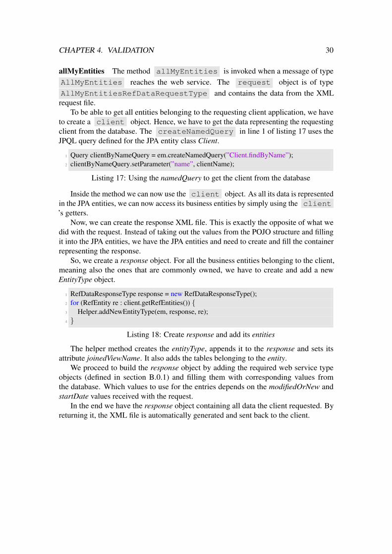
to create a client object. Hence, we have to get the data representing the requestingclient from the database. The createNamedQuery in line 1 of listing 17 uses theJPQL query defined for the JPA entity class Client.
1 Query clientByNameQuery = em.createNamedQuery(”Client.findByName”);2 clientByNameQuery.setParameter(”name”, clientName);
Listing 17: Using the namedQuery to get the client from the database
Inside the method we can now use the client object. As all its data is representedin the JPA entities, we can now access its business entities by simply using the client’s getters.
Now, we can create the response XML file. This is exactly the opposite of what wedid with the request. Instead of taking out the values from the POJO structure and fillingit into the JPA entities, we have the JPA entities and need to create and fill the containerrepresenting the response.
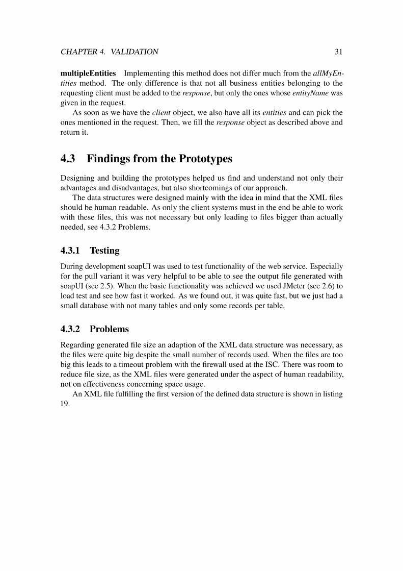
So, we create a response object. For all the business entities belonging to the client,meaning also the ones that are commonly owned, we have to create and add a newEntityType object.
1 RefDataResponseType response = new RefDataResponseType();2 for (RefEntity re : client.getRefEntities()) {3 Helper.addNewEntityType(em, response, re);4 }
Listing 18: Create response and add its entities
The helper method creates the entityType, appends it to the response and sets itsattribute joinedViewName. It also adds the tables belonging to the entity.
We proceed to build the response object by adding the required web service typeobjects (defined in section B.0.1) and filling them with corresponding values fromthe database. Which values to use for the entries depends on the modifiedOrNew andstartDate values received with the request.
In the end we have the response object containing all data the client requested. Byreturning it, the XML file is automatically generated and sent back to the client.
CHAPTER 4. VALIDATION 31
multipleEntities Implementing this method does not differ much from the allMyEn-tities method. The only difference is that not all business entities belonging to therequesting client must be added to the response, but only the ones whose entityName wasgiven in the request.
As soon as we have the client object, we also have all its entities and can pick theones mentioned in the request. Then, we fill the response object as described above andreturn it.
4.3 Findings from the PrototypesDesigning and building the prototypes helped us find and understand not only theiradvantages and disadvantages, but also shortcomings of our approach.
The data structures were designed mainly with the idea in mind that the XML filesshould be human readable. As only the client systems must in the end be able to workwith these files, this was not necessary but only leading to files bigger than actuallyneeded, see 4.3.2 Problems.
4.3.1 TestingDuring development soapUI was used to test functionality of the web service. Especiallyfor the pull variant it was very helpful to be able to see the output file generated withsoapUI (see 2.5). When the basic functionality was achieved we used JMeter (see 2.6) toload test and see how fast it worked. As we found out, it was quite fast, but we just had asmall database with not many tables and only some records per table.
4.3.2 ProblemsRegarding generated file size an adaption of the XML data structure was necessary, asthe files were quite big despite the small number of records used. When the files are toobig this leads to a timeout problem with the firewall used at the ISC. There was room toreduce file size, as the XML files were generated under the aspect of human readability,not on effectiveness concerning space usage.
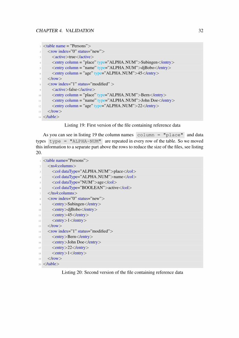
An XML file fulfilling the first version of the defined data structure is shown in listing19.
CHAPTER 4. VALIDATION 32
1 <table name = ”Persons”>2 <row index=”0” status=”new”>3 <active>true</active>4 <entry column = ”place” type=”ALPHA NUM”>Subingen</entry>5 <entry column = ”name” type=”ALPHA NUM”>djBobo</entry>6 <entry column = ”age” type=”ALPHA NUM”>45</entry>7 </row>8 <row index=”1” status=”modified” >9 <active>false</active>
10 <entry column = ”place” type=”ALPHA NUM”>Bern</entry>11 <entry column = ”name” type=”ALPHA NUM”>John Doe</entry>12 <entry column = ”age” type=”ALPHA NUM”>22</entry>13 </row>14 </table>
Listing 19: First version of the file containing reference data
As you can see in listing 19 the column names column = "place" and datatypes type = "ALPHA-NUM" are repeated in every row of the table. So we movedthis information to a separate part above the rows to reduce the size of the files, see listing20.
1 <table name=”Persons”>2 <ns4:columns>3 <col dataType=”ALPHA NUM”>place</col>4 <col dataType=”ALPHA NUM”>name</col>5 <col dataType=”NUM”>age</col>6 <col dataType=”BOOLEAN”>active</col>7 </ns4:columns>8 <row index=”0” status=”new”>9 <entry>Subingen</entry>
10 <entry>djBobo</entry>11 <entry>45</entry>12 <entry>1</entry>13 </row>14 <row index=”1” status=”modified”>15 <entry>Bern</entry>16 <entry>John Doe</entry>17 <entry>22</entry>18 <entry>1</entry>19 </row>20 </table>
Listing 20: Second version of the file containing reference data

CHAPTER 4. VALIDATION 33
Furthermore the information whether the row, meaning one record, is active or notwas at first in a separate tag. This makes sense when the file must be human readable,but does not improve machine readability. Also, it needs more CPU time to treat thiscolumn different from the others.
Even though on the first glance the second version in listing 20 seems to be usingmore space, the opposite is true, more so with increasing number of rows. With theseadaptions file size was reduced significantly.
To check the adaptions and to be sure that such issues caused by a database muchsmaller than the original do not occur any more we were provided with a mock databasewith a similar size following the prescribed meta data model. Our tests with the mockdatabase confirmed our suspicion that this new format reduced the average response sizesignificantly.
5Conclusion and Future Work
After establishing requirements with stakeholders, and then building and improvingprototypes, our understanding of the different options for replication mechanisms hasimproved. This section summarises our thoughts about past work and future work onreference data replication.
5.1 ConclusionsBy analysing ZEMIS Ref and the applications interacting with it weak points could beidentified and improvements could be proposed. Even though the prototypes were stillin construction, the analysis of ZEMIS Ref and its architecture showed us that there isa lot potential for improvements. The proposal of push architecture with caching (see3.2.1) already gave an application currently under development the opportunity to beindependent of the prescribed data scheme, see 5.3.
The meta data model was not significantly adapted as intended, because the futureapplication design is still undetermined.
34

CHAPTER 5. CONCLUSION AND FUTURE WORK 35
5.2 Future WorkThe application ZEMIS Ref is End-Of-Life as its web technology reached End-Of-Lifein 2013. This presents security risks. Additionally, a rewrite of most parts of the systemis required because a significant part of the business logic has been integrated into theweb layer.
5.2.1 Management of Reference Data trough ClientsAs reference data can actually be owned by a ZEMIS Ref client application, the ideacame up to let the clients create new entities in their owned tables. This is not possiblewith any of the proposed variants, nor with the initial state, but could be an improvement.That way entities only used by one application could be managed by the applicationitself. A client application currently can only be owner of an entity if no other applicationneeds it, so there would be no problem concerning data synchronicity, provided this doesnot change.
5.2.2 Extended FunctionalityThe functionality provided by ZEMIS Ref is very basic and was designed only for thepurpose to manage reference data by occasional changes. Usage is time consumingand very ineffective. For the expected growing numbers of applications needing thisdata, including applications outside the scope of project ZEMIS, there is a need forimprovement.
5.3 Developments of Needs and CircumstancesThe ISC currently develops a new application that is part of the ZEMIS landscape. AsZEMIS Ref is going to be overhauled in the next few years, they decided to in a first stepalready develop the new application in a way that decouples it from the direct databaseaccess, but that offers a web service interface over which ZEMIS Ref can push changes,thus following the push architecture with caching approach described in 3.2.1. It meansmore work for them in the moment, but less so later, as the application does not have tobe adapted as soon as ZEMIS Ref is overhauled.
The decision to use this approach rather than the pull approach is based on the factthat it is closest to the initial state and thus affects ZEMIS Ref the least. So it is thecheapest and easiest solution for the moment, as only minor changes to ZEMIS Ref areneeded. It is planned to use the pull architecture with caching approach described in3.2.3 in the next step, when ZEMIS Ref is rewritten.

AAnleitung zu wissenschaftlichen Arbeiten
This chapter shall work as a guide on how to implement a prototype for data exchangebetween several applications by using RabbitMQ [11]. It is assumed that one of theseapplications is working as central application that must supply the other applicationswith the data they need. You should have some basic knowledge of Java programming.
A.1 BackgroundRabbitMQ is an open source message broker implementing Advanced Message QueuingProtocol (AMQP) [10]. This protocol is an open standard that allows passing of messagesbetween various kinds of applications. It enhances interoperational communication andsharing of resources and thus facilitates building service oriented architectures.
AMQP has the following viewpoint:
”[...] messages are published to exchanges, which are often compared to postoffices or mailboxes. Exchanges then distribute message copies to queuesusing rules called bindings. Then AMQP brokers either deliver messagesto consumers subscribed to queues, or consumers fetch/pull messages fromqueues on demand.” [13].
It was originally designed for the banking industry, thus is secure and reliable andfocuses on interoperability [10], hence it should fit the requirements for our purpose.
Figure A.1 shows the basic concept of the AMQP protocol.
36

APPENDIX A. ANLEITUNG ZU WISSENSCHAFTLICHEN ARBEITEN 37
Figure A.1: Conceptual figure of Advanced Message Queuing Protocol [16]
As you can see, publishers (also called producers) send messages to the messagebroker that then routes them to consumers that process the messages. RabbitMQ is sucha message broker.
A.1.1 Basic ConceptsThe following terms are used to describe the basic concepts used for building such a dataexchange infrastructure.
Producer This is the application that produces and sends messages to an exchange. Italso declares the routing keys of a message.
Message A message is what is exchanged between applications via the protocol. Theproducer must provide them with a routing key that is then used for routing. In RabbitMQ,these are binary blobs of data.
Exchange Receives messages from producers and sends them further to queues. Theymust exactly know to which queue(s) a certain message should be forwarded. Four typesof exchanges are offered:
• Direct delivers messages to queues based on the message routing key. A messagegoes to the queues whose binding key exactly matches the routing key of themessage
• Topic routes messages to one or many queues based on matching between amessage routing key and the pattern that was used to bind a queue to an exchange
• Headers designed for routing on multiple attributes that are more easily expressedas message headers than a routing key

APPENDIX A. ANLEITUNG ZU WISSENSCHAFTLICHEN ARBEITEN 38
• Fanout routes messages to all of the queues that are bound to it and the routingkey is ignored
Queue Works as a buffer to store messages that can then be consumed by a consumer.
Consumer This is the application that receives the messages by consuming them fromone or more queues.
Binding Represents a relationship between an exchange and a queue. Works as a rulean exchange uses (among other things) to route messages to queues.
A.2 Developing the PrototypeBefore starting you should make sure to download and install RabbitMQ [12] on yourcomputer, as explained in the installation guide. Make sure you can start the server likein figure A.2.
Figure A.2: Starting the RabbitMQ server
A.2.1 PreparationTo start, you should look at the provided tutorials [12] to find out what setup fits best forthe specific use case. This can be done by looking at involved entities.
Producer and Consumer In our specific case we want to send reference data fromthe application ZEMIS Ref, the producer, to several other applications, the consumers.There is no need for an explicit answer message if the message sending is reliable. It ispossible to include acknowledgements, so that the producer is sure the messages werereceived and can resend them if needed.
APPENDIX A. ANLEITUNG ZU WISSENSCHAFTLICHEN ARBEITEN 39
Messages - Routing Key You should also think of a practical way on how to route themessages so they reach all consumers needing the data. This enables you to define whattype of exchange to use.
As we know (see section 2.3.1) reference data can either be owned by one singleconsumer or be commonly owned, which is defined on entity level. This means wealready have an attribute that can serve as routing key, provided that the producer createsa separate message for each entity.
Exchange Because we have only one routing key per message and a limited amount ofpossible keys that can not spontaneously change (actually number of consumers plus onefor common) we determined to use a direct exchange.
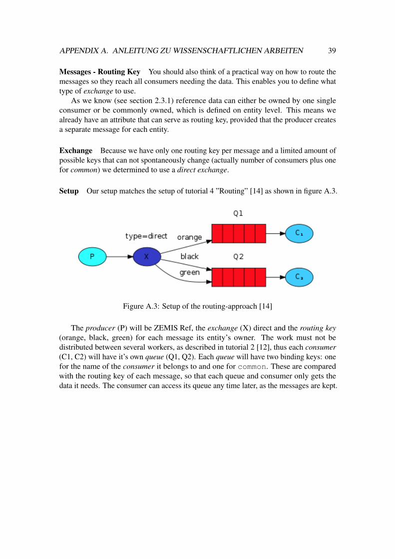
Setup Our setup matches the setup of tutorial 4 ”Routing” [14] as shown in figure A.3.
Figure A.3: Setup of the routing-approach [14]
The producer (P) will be ZEMIS Ref, the exchange (X) direct and the routing key(orange, black, green) for each message its entity’s owner. The work must not bedistributed between several workers, as described in tutorial 2 [12], thus each consumer(C1, C2) will have it’s own queue (Q1, Q2). Each queue will have two binding keys: onefor the name of the consumer it belongs to and one for common. These are comparedwith the routing key of each message, so that each queue and consumer only gets thedata it needs. The consumer can access its queue any time later, as the messages are kept.

APPENDIX A. ANLEITUNG ZU WISSENSCHAFTLICHEN ARBEITEN 40
Example C1 is the application ZEMIS, its queue Q1 thus has the binding keys zemisand common. C2 is the application MIDES, Q2 thus has the binding keys midesand common. Now a record in the commonly owned entity Zentrumsadressen ischanged. ZEMIS Ref thus creates a message with routing key common. The exchangeforwards the message to Q1 and Q2, as they both subscibed to get messages with routingkey common. When a record belonging to an entity owned by ZEMIS is mutated, onlyC1 will get this message.
A.2.2 Implementing the PrototypeFor the producer as well as each consumer a java application is needed. They mustcontain certain parts: starting the transaction, create a connection and channel to use.This is done as in listing 21.
1 //Connection2 ConnectionFactory factory = new ConnectionFactory();3 factory.setHost(”localhost”);4 Connection connection = factory.newConnection();5 //Channel6 Channel channel = connection.createChannel();7 //Add a direct exchange8 channel.exchangeDeclare(EXCHANGE NAME, BuiltinExchangeType.DIRECT);
Listing 21: Basics for setting up producer or consumer
The next steps are not the same for consumers and producers, so we look at itseparately.
A.2.2.1 Producer
For producing messages we use the structures defined to create our XML file.For this prototype we want to call the main method with the ID’s of the entities we
want to send in a message as arguments. We need to create a response with one entity foreach given id.
1 for (String id : args) {2 RefDataResponseType response = createResponse(id, em);3 ...4 }

APPENDIX A. ANLEITUNG ZU WISSENSCHAFTLICHEN ARBEITEN 41
Then, we have to serialise this response so that it can be sent as stream of bytes. Thisis done by usage of Apache serialization utils [1]. Of course, the response class mustimplement Serializable [3].
1 byte[] data = SerializationUtils.serialize(response);
Next, we have to set the routing key. As defined (paragraph A.2.1 Messages - RoutingKey) we take the joinedViewName of the first (and only) entity in the response.
1 String key = response.getRefEntity().get(0).getJoinedViewName();
We now have to publish the previously defined byte array data with the definedrouting key and publish it via the created exchange. This is the actual sending ofthe message.
1 channel.basicPublish(EXCHANGE NAME, key, null, data);
A.2.2.2 Consumer
For the consumer you have to define which exchange to use for that channel and to createthe queue and its bindings. We will use the same exchange as for the producer.
1 channel.exchangeDeclare(EXCHANGE NAME, BuiltinExchangeType.DIRECT);2 String queueName = channel.queueDeclare().getQueue();3
4 channel.queueBind(queueName, EXCHANGE NAME, ”MIDES”);5 channel.queueBind(queueName, EXCHANGE NAME, ”COMMON”);
This consumer represents the application MIDES and thus wants to get all messageswith routing key ”MIDES” or ”COMMON”.
Next you need to create the consumer itself that overrides the handleDeliverymethod and let it consume messages from the queue:

APPENDIX A. ANLEITUNG ZU WISSENSCHAFTLICHEN ARBEITEN 42
1 Consumer consumer = new DefaultConsumer(channel) {2 @Override3 public void handleDelivery(String consumerTag, Envelope envelope,4 AMQP.BasicProperties properties, byte[] body) throws IOException {5 RefDataResponseType response =6 (RefDataResponseType)SerializationUtils.deserialize(body);7
8 };9 channel.basicConsume(queueName, true, consumer);
We deserialise the content back to a RefDataResponseType that can be used byMIDES to update its database.
A.2.3 ConclusionThis prototype shows a basic example of how to use RabbitMQ as a replication mech-anism. It works independent of the application architectures used and is secure andreliable. Various usage scenarios are possible, so that it can be adapted according to theneeds. The effort of using a message oriented middleware such as RabbitMQ seems tobe very small in comparison to a web service oriented architecture.
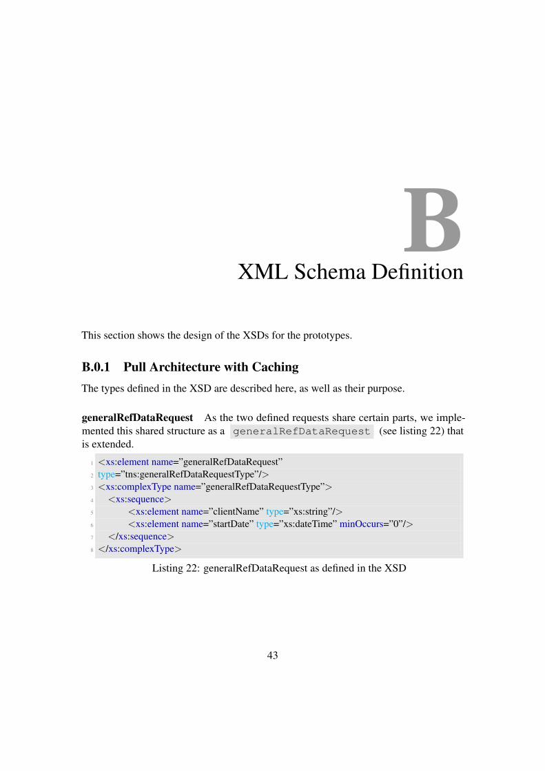
BXML Schema Definition
This section shows the design of the XSDs for the prototypes.
B.0.1 Pull Architecture with CachingThe types defined in the XSD are described here, as well as their purpose.
generalRefDataRequest As the two defined requests share certain parts, we imple-mented this shared structure as a generalRefDataRequest (see listing 22) thatis extended.
1 <xs:element name=”generalRefDataRequest”2 type=”tns:generalRefDataRequestType”/>3 <xs:complexType name=”generalRefDataRequestType”>4 <xs:sequence>5 <xs:element name=”clientName” type=”xs:string”/>6 <xs:element name=”startDate” type=”xs:dateTime” minOccurs=”0”/>7 </xs:sequence>8 </xs:complexType>
Listing 22: generalRefDataRequest as defined in the XSD
43

APPENDIX B. XML Schema Definition 44
The generalRefDataRequest expects name of the client application asclientName . In the initial meta data model, this would be the description (seesection 2.3.1 Meta Data Model). Also, because there might be influences that mess upthe client’s database, we figured that the client should be able to override the date fromwhich on data changes shall be considered. So also the optional tag startDate thatcan be used to provide a date to use instead of the stored date of the last pull.
The two request messages extending the generalRefDataRequest can actu-ally be used by the client applications. They are shown in listings 23 and 25 and shortlyexplained here.
allMyEntitiesRefDataRequest The allMyEntitiesRefDataRequest addsa modifiedOrNew (See paragraph B.0.1 modifiedOrNew) element that can be set totrue to solely get records modified or newly created since the startDate or thestored date of the last pull, respectively. It is set to false per default and must occur atleast 0 times, which means it is optional.
1 <xs:complexType name=”allMyEntitiesRefDataRequestType”>2 <xs:complexContent>3 <xs:extension base=”tns:generalRefDataRequestType”>4 <xs:sequence>5 <xs:element name=”modifiedOrNew” type=”tns:modifiedOrNewType”6 minOccurs=”0” default=”false”/>7 </xs:sequence>8 </xs:extension>9 </xs:complexContent>
10 </xs:complexType>
Listing 23: allMyEntitiesRefDataRequest request as defined in the XSD
An example for a allMyEntitiesRefDataRequest from client systemMIDES that pulls all values modified or newly created after the tenth of September, 2017is shown in listing 24.
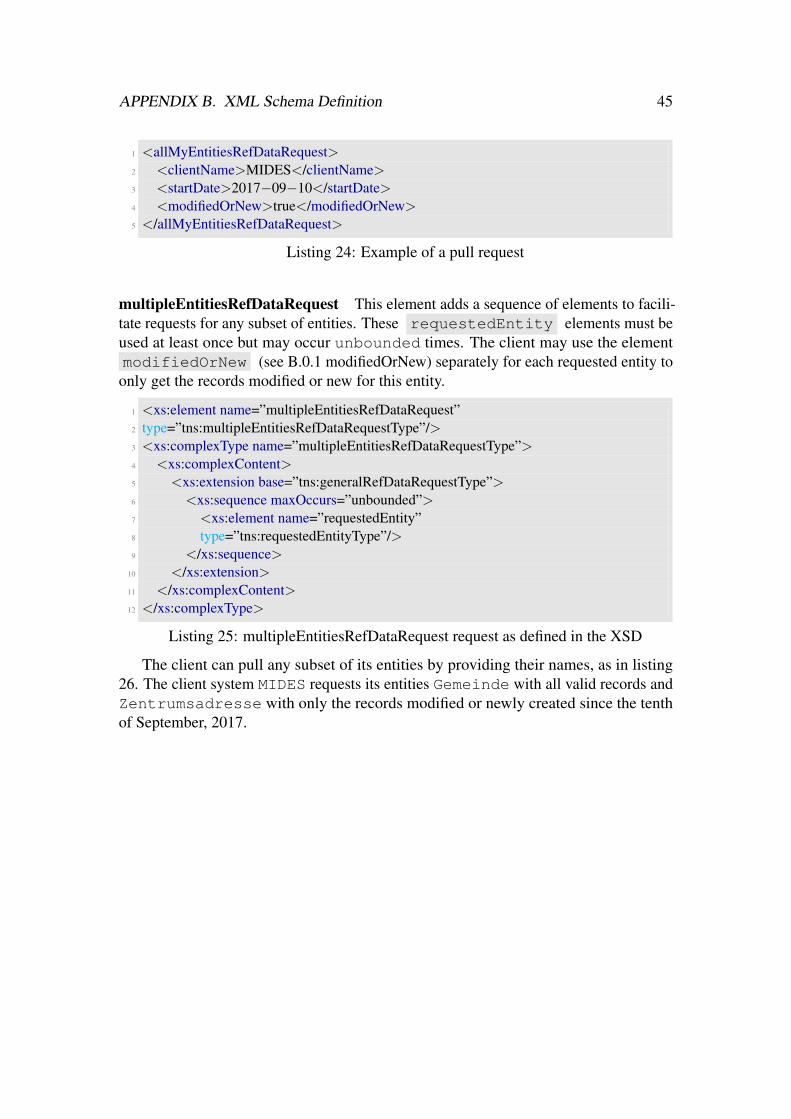
APPENDIX B. XML Schema Definition 45
1 <allMyEntitiesRefDataRequest>2 <clientName>MIDES</clientName>3 <startDate>2017−09−10</startDate>4 <modifiedOrNew>true</modifiedOrNew>5 </allMyEntitiesRefDataRequest>
Listing 24: Example of a pull request
multipleEntitiesRefDataRequest This element adds a sequence of elements to facili-tate requests for any subset of entities. These requestedEntity elements must beused at least once but may occur unbounded times. The client may use the elementmodifiedOrNew (see B.0.1 modifiedOrNew) separately for each requested entity to
only get the records modified or new for this entity.
1 <xs:element name=”multipleEntitiesRefDataRequest”2 type=”tns:multipleEntitiesRefDataRequestType”/>3 <xs:complexType name=”multipleEntitiesRefDataRequestType”>4 <xs:complexContent>5 <xs:extension base=”tns:generalRefDataRequestType”>6 <xs:sequence maxOccurs=”unbounded”>7 <xs:element name=”requestedEntity”8 type=”tns:requestedEntityType”/>9 </xs:sequence>
10 </xs:extension>11 </xs:complexContent>12 </xs:complexType>
Listing 25: multipleEntitiesRefDataRequest request as defined in the XSD
The client can pull any subset of its entities by providing their names, as in listing26. The client system MIDES requests its entities Gemeinde with all valid records andZentrumsadresse with only the records modified or newly created since the tenthof September, 2017.

APPENDIX B. XML Schema Definition 46
1 <?xml version=”1.0” encoding=”UTF−8” standalone =”yes”?>2 <allMyEntitiesRefDataRequest xmlns=”http://ejpd.admin.ch/sem/zemis3 /refdataservice/types/v1”>4 <multipleEntitiesRefDataRequest>5 <clientName>MIDES</clientName>6 <startDate>2017−09−10</startDate>7 <requestedEntity>8 <entityName>Gemeinde</entityName>9 <modifiedOrNew>true</modifiedOrNew>
10 </requestedEntity>11 <requestedEntity>12 <entityName>Zentrumsadresse</entityName>13 <modifiedOrNew>false</modifiedOrNew>14 </requestedEntity>15 </allMyEntitiesRefDataRequest>
Listing 26: Example of a pull request for several entities
modifiedOrNew The element modifiedOrNew is defined in the XSD as follows(listing 27). The type is defined as boolean and thus an XML file using thiselement must send a value defined as boolean by the schema definition referenced withthe namespace xs , these are true or 1 and false or 0.
1 <xs:simpleType name=”modifiedOrNewType”>2 <xs:restriction base=”xs:boolean”/>3 </xs:simpleType>
Listing 27: modifiedOrNew Type defined in the XSD
It is optional for both requests and assumed false if not given. If set to truethe client only gets the delta, meaning the records modified or newly created since hislast pull. Having this element provides a possibility to not only pull deltas, but alsoall valid records, for example as initial pull or occasionally to make sure there are noinconsistencies. As different clients have different needs, we let the client choose whatto get in the response.
refDataResponse The refDataResponse contains all data requested by theclient. It was designed in the beginning, but then later redesigned, along with the typesused for the response. The first version is shown here in listing 28, while the final versioncan bee seen in section Testing 4.3.1.
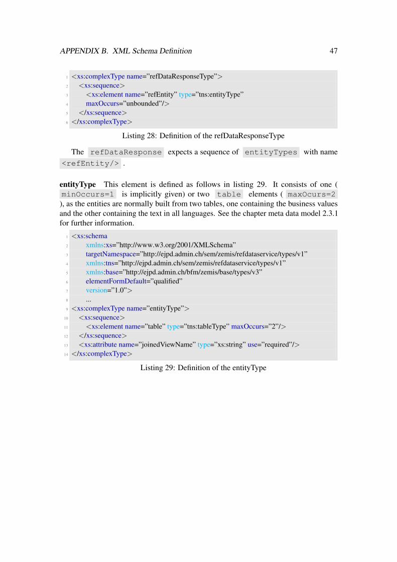
APPENDIX B. XML Schema Definition 47
1 <xs:complexType name=”refDataResponseType”>2 <xs:sequence>3 <xs:element name=”refEntity” type=”tns:entityType”4 maxOccurs=”unbounded”/>5 </xs:sequence>6 </xs:complexType>
Listing 28: Definition of the refDataResponseType
The refDataResponse expects a sequence of entityTypes with name<refEntity/> .
entityType This element is defined as follows in listing 29. It consists of one (minOccurs=1 is implicitly given) or two table elements ( maxOcurs=2), as the entities are normally built from two tables, one containing the business valuesand the other containing the text in all languages. See the chapter meta data model 2.3.1for further information.
1 <xs:schema2 xmlns:xs=”http://www.w3.org/2001/XMLSchema”3 targetNamespace=”http://ejpd.admin.ch/sem/zemis/refdataservice/types/v1”4 xmlns:tns=”http://ejpd.admin.ch/sem/zemis/refdataservice/types/v1”5 xmlns:base=”http://ejpd.admin.ch/bfm/zemis/base/types/v3”6 elementFormDefault=”qualified”7 version=”1.0”>8 ...9 <xs:complexType name=”entityType”>
10 <xs:sequence>11 <xs:element name=”table” type=”tns:tableType” maxOccurs=”2”/>12 </xs:sequence>13 <xs:attribute name=”joinedViewName” type=”xs:string” use=”required”/>14 </xs:complexType>
Listing 29: Definition of the entityType
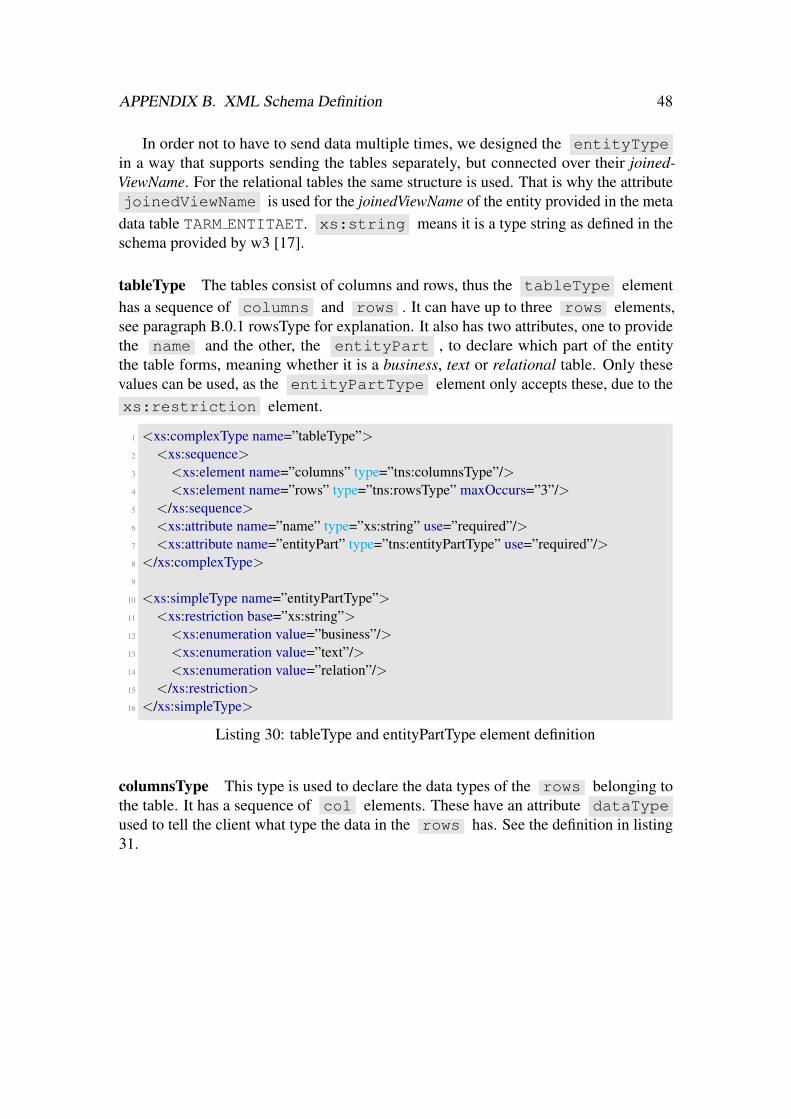
APPENDIX B. XML Schema Definition 48
In order not to have to send data multiple times, we designed the entityTypein a way that supports sending the tables separately, but connected over their joined-ViewName. For the relational tables the same structure is used. That is why the attributejoinedViewName is used for the joinedViewName of the entity provided in the meta
data table TARM ENTITAET. xs:string means it is a type string as defined in theschema provided by w3 [17].
tableType The tables consist of columns and rows, thus the tableType elementhas a sequence of columns and rows . It can have up to three rows elements,see paragraph B.0.1 rowsType for explanation. It also has two attributes, one to providethe name and the other, the entityPart , to declare which part of the entitythe table forms, meaning whether it is a business, text or relational table. Only thesevalues can be used, as the entityPartType element only accepts these, due to thexs:restriction element.
1 <xs:complexType name=”tableType”>2 <xs:sequence>3 <xs:element name=”columns” type=”tns:columnsType”/>4 <xs:element name=”rows” type=”tns:rowsType” maxOccurs=”3”/>5 </xs:sequence>6 <xs:attribute name=”name” type=”xs:string” use=”required”/>7 <xs:attribute name=”entityPart” type=”tns:entityPartType” use=”required”/>8 </xs:complexType>9
10 <xs:simpleType name=”entityPartType”>11 <xs:restriction base=”xs:string”>12 <xs:enumeration value=”business”/>13 <xs:enumeration value=”text”/>14 <xs:enumeration value=”relation”/>15 </xs:restriction>16 </xs:simpleType>
Listing 30: tableType and entityPartType element definition
columnsType This type is used to declare the data types of the rows belonging tothe table. It has a sequence of col elements. These have an attribute dataTypeused to tell the client what type the data in the rows has. See the definition in listing31.

APPENDIX B. XML Schema Definition 49
1 <xs:complexType name=”columnsType”>2 <xs:sequence>3 <xs:element name=”col” type=”tns:colType” maxOccurs=”unbounded”/>4 </xs:sequence>5 </xs:complexType>6
7 <xs:complexType name=”colType”>8 <xs:simpleContent>9 <xs:extension base=”xs:string”>
10 <xs:attribute name=”dataType” type=”tns:dataTypeType”/>11 </xs:extension>12 </xs:simpleContent>13 </xs:complexType>14
15 <xs:simpleType name=”dataTypeType”>16 <xs:restriction base=”xs:string”>17 <xs:enumeration value=”ALPHA NUM”/>18 <xs:enumeration value=”NUM”/>19 <xs:enumeration value=”BETRAG”/>20 <xs:enumeration value=”DATUM”/>21 <xs:enumeration value=”BOOLEAN”/>22 <xs:enumeration value=”RATIONAL”/>23 <xs:enumeration value=”CLOB”/>24 </xs:restriction>25 </xs:simpleType>
Listing 31: columnType and dataTypeType element definition
As you can see from, line 15 on (in listing 31) there are seven datatypes referencedata can be associated with.

APPENDIX B. XML Schema Definition 50
rowsType As this type is used to group old, modified and new row elements, ithas the attribute status that only accepts these values and a sequence of rowelements. For each status one group of rows is sent. See listing 32.
1 <xs:complexType name=”rowsType”>2 <xs:sequence>3 <xs:element name=”row” type=”tns:rowType” minOccurs=”0” maxOccurs=”
unbounded”/>4 </xs:sequence>5 <xs:attribute name=”status” type=”tns:statusType” use=”optional”/>6 </xs:complexType>7
8 <xs:complexType name=”rowType”>9 <xs:sequence>
10 <xs:element name=”entry” type=”tns:entryType” maxOccurs=”unbounded”/>11 </xs:sequence>12 <xs:attribute name=”index” type=”xs:int” use=”required”/>13 </xs:complexType>14
15 <xs:simpleType name=”statusType”>16 <xs:restriction base=”xs:string”>17 <xs:enumeration value=”old”/>18 <xs:enumeration value=”new”/>19 <xs:enumeration value=”modified”/>20 </xs:restriction>21 </xs:simpleType>
Listing 32: rowType element definition
The rowType has entry elements that contain the data. It has a requiredindex attribute that is used to count the rows.

APPENDIX B. XML Schema Definition 51
Example Listing 33 shows an example for a response XML file that follows the schemadefinition described, thus the final version of the XSD.
1 <ns4:refDataResponse xmlns:ns4=”http://...” xmlns=”http://...”>2 <ns4:refEntity joinedViewName=”VARP EMENDATION”>3 <ns4:table name=”VARP EMENDATION BS” entityPart=”business”>4 <ns4:columns>5 <ns4:col dataType=”ALPHA NUM”>KEYCD</ns4:col>6 <ns4:col dataType=”NUM”>TAGESGERICHT</ns4:col>7 <ns4:col dataType=”ALPHA NUM”>WAHLLOKAL</ns4:col>8 <ns4:col dataType=”BOOLEAN”>CTL ACT CD</ns4:col>9 </ns4:columns>
10 <ns4:rows status=”old”>11 <ns4:row index=”0”>12 <ns4:entry>asw</ns4:entry>13 <ns4:entry>357766</ns4:entry>14 <ns4:entry>q</ns4:entry>15 <ns4:entry>1</ns4:entry>16 </ns4:row>17 ...18 </ns4:rows>19 <ns4:rows status=”modified”>20 <ns4:row index=”0”>21 ...22 </ns4:row>23 ...24 </ns4:rows>25 <ns4:rows status=”new”>26 <ns4:row index=”0”>27 ...28 </ns4:row>29 </ns4:rows>30 ...31 </ns4:table>32 ...33 </ns4:refEntity>34 ...35 </ns4:refDataResponse>
Listing 33: Example of a response XML file

APPENDIX B. XML Schema Definition 52
B.0.2 Push ArchitectureThe response structure defined for the pull architecture with caching (see B.0.1 ref-DataResponse) must only be renamed, as it should be a refDataRequestType
instead of a refDataResponseType .
1 <xs:complexType name=”refDataRequestType”>2 <xs:sequence>3 <xs:element name=”refEntity” type=”tns:entityType”4 maxOccurs=”unbounded”/>5 </xs:sequence>6 </xs:complexType>
Listing 34: Definition of the refDataRequestType
The structure must not be adapted, and all elements defined for the pull architecturewith caching can be reused. An additional messageId element might be useful tobe able to map request messages to response messages, preferably in the soap headerelement [2]. This must then also be included in the according response message.

CDeclaration
”Ich erklare hiermit, dass ich diese Arbeit selbststandig verfasst und keine anderen alsdie angegebenen Quellen benutzt habe. Alle Stellen, die wortlich oder sinngemassaus Quellen entnommen wurden, habe ich als solche gekennzeichnet. Mir ist bekannt,dass andernfalls der Senat gemass Artikel 36 Absatz 1 Buchstabe r des Gesetzes vom 5.September 1996 uber die Universitat zum Entzug des auf Grund dieser Arbeit verliehenenTitels berechtigt ist.”
53

DInterviews
D.1 Questions for Adrian BurkiGeneral Questions
Q: What are advantages of having your own tables?
A: Having my own tables is more flexible and probably a bit more lightweight. Dowe really need bi-temporal data storage? If not, I can just do without. Do we reallyneed categories and additional parameters? If not, no need to have it in the model.However using an existing component with its data model has advantages of itsown, no need to reinvent the wheel.
Q: Would you like to use full pulls periodically or prefer deltas?
A: I’m perfectly fine with deltas. In case of an incident (inconsistency) an option toforce a full sync would be nice though.
Q: How many users for Adeya/eRetour?
A: The application consist of four parts which will be build one after the other. Forversion one there will be two teams at SEM and a handful of specialist at theCantons accessing the application. So there will be couple of hundred users. Lateron the numbers will go up, but I assume it will never be much more than a thousand.
54

APPENDIX D. INTERVIEWS 55
Q: Do you want to have new entries when they get active or before, including infor-mation about when they will be active?
A: I don’t need to get entries before they are active. What I need though, are oldentries which are inactive, since there may be old data referencing these non-activeentries.
Variant 1: Push Architecture
A: I don’t like the Hollywood approach (don’t call us, we call you). I want to be incharge, I want to tell when to sync and what to sync. I don’t want to wait for thepush to happen. As far as I know we have kind of a pull is preferred over pushpolicy from the architecture point of view. So I would expect opposition, if youhave to present this solution in front of the architecture board.
A: What about on the fly adding entries from the client? Can I have my own UI in theclient and push new entries to the central Ref-data store?
Q: Two-phase commit: Is voting an option, or too much effort? What do you thinkabout it?
A: I don’t quite get question about voting. The central Ref-data store is the master,why would you allow a client to vote against using the data?
Q: Commit and abort methods must be defined - is it a lot of effort?
A: Clients need to provide a web service to which Zemis-ref can push changes. That’sall the web service must be able to do, plus giving an answer. You then must beable to add them to your database. What do you think about this?
Variant 2: Direct Pull Architecture
A: The web 3.0 approach, data is in the cloud and readily available. That works forall the weather apps out there, so why should it not work for us. We may have todo some caching in the browser, but all single page JavaScript apps can do thatjust fine.
A: The central Ref-data store has to guarantee, that no entries are deleted. Entries canbe deactivated but never be deleted, so that the key can still be referenced. I don’tmind loosing referential integrity on the database layer.
A: Same question as above, can I add new entries from the client? My users want todynamically add new values if ‘purple with a shade of grey’ is missing from thelist of hair color.

APPENDIX D. INTERVIEWS 56
Q: You do not have your own tables, but always pull when you need a value. Is thatan advantage?
• No need to store the data
• No need to update the data - always up to date
• No need to keep version tracking
Q: What about performance? Would your application be in trouble if it takes longerfor a request to be fulfilled? If yes, do you have an idea how to avoid this?
Q: Do you think a backup solution is mandatory? What might be possible as backupsolution?
Q: What about referential integrity?
Variant 3: Pull Architecture with Caching
A: That is the approach I prefer. The setup is quite similar to what we have in ourinternal code table solution, except that it is using web services instead of batches.On top of that I can cache the data in my own structure, no need to store everythingif parts are not needed in my application.
Q: You do not have to implement a web service, but only a web service client to pullfrom the web service provided by Zemis-ref.
Q: You need to cache the data. Costs? Better to cache the data than always having topull (including performance issues)?
Q: How often do you think pulls are needed?
A: We would be pulling at least once a day. Actually once every three hours would berealistic.
Variant 4: Push notify to pull
A: I kind of like that approach as well. Although we have to talk about technology, ifyou want to do notification broadcasts. Web services does not feel right, that begsfor a messaging infrastructure - JMS topics comes to mind.
A: Reading through the question I think is too much of a hassle and a lot of work for avery limited use case. If an application requires real-time data, let them pull everyfive minutes, problem solved.
Q: How hard is it to implement a web service to get notifications?
APPENDIX D. INTERVIEWS 57
• Web service client: only pull delta
• What format would be convenient for you? What could you imagine?
Q: What information is needed to determine whether a pull is required?
Q: How much effort is it to write code to determine whether to pull or not, dependingon this information?
Q: How bad are the disadvantages?
• Clients need to offer a web service and a web service client interface (Zemis-ref also)
• Clients need to cache the ref data
• Clients need to determine whether to pull or not, depending on the informationincluded in the notification
• Performance must be good even if all clients pull together which is almostguaranteed
• Requests can be answered with an offset in between
• Zemis ref needs knowledge for deltas (like time, version)
Q: Notification includes the following, do you agree?
• Information about the change, at least which table, so clients can determinewhether to pull or not, at least for b)
• ID for the status change/notification to avoid unnecessary double-pulls
D.2 Questions and Answers: Didier SpicherQ: Durfen alle auf alle Tabellen zugreifen? Oder braucht es eine Einschrankung?
A: Mit ist besser
Q: Wie oft kommt es vor, dass auf Produktion Eintrage fur denselben Tag vorbereitetwerden? Laut Marlene ofters, sie macht das so fur sedex und Meldeverfahren, derSupport anscheinend auch. Ware es schlimm, wenn man Anderungen nicht amselben Tag publizieren konnte?
A: Kommt vor, sollte schnell sein. Auf Test sehr schnell (konfigurierbar?)
Q: Push: Schlimm, wenn es bei einem Client fehlt und dieser die Daten erst spaterhat? Two-phase commit notig oder ubertrieben?

APPENDIX D. INTERVIEWS 58
A: Kurze Zeit nicht schlimm, so zB eine halbe Stunde ist kein Problem
Q: Ist die Historisierung so wie sie jetzt ist ok?
A: Habe ich noch nicht angeschaut
Q: Sollen Clients neue Eintrage hinzufugen durfen? Neue Tabellen?
A: Eintrage in der eigenen Tabelle ok, neue Tabellen auch. Eher als Addon anschauen
Q: Durfen Clients ihre eigenen Tabellen/Daten erfassen? Berechtigung, data owner?Wie sehr muss das eingeschrankt werden?
A: Nur eigene, nicht diejenigen von anderen Applikationen oder die COMMON-Tabellen
A: Zugriffberechtigung soll so bleiben wie bisher (GUI)

Bibliography
[1] SerializationUtils (Apache Commons Lang 3.7 API). https://commons.apache.org/proper/commons-lang/apidocs/org/apache/commons/lang3/SerializationUtils.html, 2001-2017. Accessed:2018-03-03.
[2] John Ibbotson. SOAP Version 1.2 Usage Scenarios. W3C note, W3C, July 2003.http://www.w3.org/TR/2003/NOTE-xmlp-scenarios-20030730/#S5.
[3] Serializable (Java Platform SE 8 ). https://docs.oracle.com/javase/8/docs/api/java/io/Serializable.html, 2017. Accessed: 2018-03-03.
[4] Java API for XML Web Services. https://docs.oracle.com/javase/7/docs/technotes/guides/xml/jax-ws/, 2007. Accessed: 2018-03-03.
[5] Apache JMeter - Apache JMeter™. http://jmeter.apache.org. Accessed:2018-01-24.
[6] The Java Community Process(SM) Program - JSRs: Java Specification Requests- detail JSR# 317. https://jcp.org/en/jsr/detail?id=317, 2018.Accessed: 2018-03-03.
[7] Martin Kalin. Java Web Services: Up and Running: A Quick, Practical, andThorough Introduction. ” O’Reilly Media, Inc.”, 2013.
[8] Noah Mendelsohn, Yves Lafon, Henrik Frystyk Nielsen, Anish Karmarkar, Jean-Jacques Moreau, Martin Gudgin, and Marc Hadley. SOAP Version 1.2 Part 1:Messaging Framework (Second Edition). W3C recommendation, W3C, April 2007.http://www.w3.org/TR/2007/REC-soap12-part1-20070427/.
[9] SR 142.314 Asylverordnung 3 vom 11. August 1999 uber die Bearbeitung von Per-sonendaten (Asylverordnung 3, AsylV 3). https://www.admin.ch/opc/de/classified-compilation/19994786/index.html#a1a, 2018.Accessed: 2018-03-03.
59

BIBLIOGRAPHY 60
[10] OASIS. Advanced Message Queuing Protocol (AMQP) Version1.0. http://docs.oasis-open.org/amqp/core/v1.0/amqp-core-complete-v1.0.pdf, 2012. Accessed: 2018-03-02.
[11] RabbitMQ - Messaging that just works. https://www.rabbitmq.com, 2007.Accessed: 2018-03-02.
[12] RabbitMQ - Getting started with RabbitMQ. https://www.rabbitmq.com/getstarted.html, 2007. Accessed: 2018-02-28.
[13] RabbitMQ - AMQP 0-9-1 Model Explained. https://www.rabbitmq.com/tutorials/amqp-concepts.html, 2007. Accessed: 2018-03-02.
[14] RabbitMQ - RabbitMQ tutorial - Routing. https://www.rabbitmq.com/tutorials/tutorial-four-java.html, 2007. Accessed: 2018-03-01.
[15] REST & SOAP Automated API Testing Tool — SoapUI. https://www.soapui.org. Accessed: 2018-01-24.
[16] Spring tutorials: Rabbit MQ basic concepts. http://springguide.blogspot.ch/2015/03/rabbit-mq-and-spring-amqp-basics.html, 2015. Accessed: 2018-03-01.
[17] XML Schema. http://www.w3.org/2001/XMLSchema, 2014. Accessed:2018-02-26.
[18] Verordnung uber das Zentrale Migrationsinformationssystem (ZEMIS). https://www.sem.admin.ch/sem/de/home/aktuell/gesetzgebung/archiv/vo_zemis.html, 2007. Accessed: 2018-03-03.