Repetitive Impact Exposure in DoD Vehicles€¦ · · 2014-07-15Repetitive Impact Exposure in DoD...
98
Reducing Vibration and Repetitive Impact Exposure in DoD Vehicles Quick Reference Guide Model Language for Acquisition Programs Suggestions for Fielded Systems References Test & Evaluation Master Plan (TEMP) Standards Suggestions for Fielded System System Performance Specification (SPS) Systems Engineering Plan (SEP) Capability Development Document (CDD) Request for Proposal (RFP) Analysis of Alternatives (AoA) Repetitive Impact DOTmLPF-P Change Recommendation (DCR) Table of Contents Introduction Whole-Body Vibration Initial Capabilities Document (ICD)
-
Upload
phungtuyen -
Category
Documents
-
view
215 -
download
0
Transcript of Repetitive Impact Exposure in DoD Vehicles€¦ · · 2014-07-15Repetitive Impact Exposure in DoD...

Reducing Vibration and
Repetitive Impact Exposure in
DoD Vehicles
Quick Reference Guide
Model Language for Acquisition Programs Suggestions for Fielded Systems
References
Test & Evaluation Master
Plan (TEMP)
Standards
Suggestions for
Fielded System
System Performance
Specification (SPS)
Systems Engineering
Plan (SEP)
Capability Development
Document (CDD)
Request for Proposal
(RFP)
Analysis of
Alternatives (AoA)
Repetitive Impact
DOTmLPF-P Change
Recommendation (DCR)
Table of Contents
Introduction
Whole-Body Vibration
Initial Capabilities
Document (ICD)
2
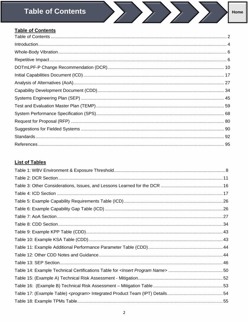
Table of Contents
Table of Contents ........................................................................................................................................... 2
Introduction ..................................................................................................................................................... 4
Whole-Body Vibration ..................................................................................................................................... 6
Repetitive Impact ............................................................................................................................................ 6
DOTmLPF-P Change Recommendation (DCR) ............................................................................................ 10
Initial Capabilities Document (ICD) ............................................................................................................... 17
Analysis of Alternatives (AoA)....................................................................................................................... 27
Capability Development Document (CDD) .................................................................................................... 34
Systems Engineering Plan (SEP) ................................................................................................................. 45
Test and Evaluation Master Plan (TEMP) ..................................................................................................... 59
System Performance Specification (SPS) ..................................................................................................... 68
Request for Proposal (RFP) ......................................................................................................................... 80
Suggestions for Fielded Systems ................................................................................................................. 90
Standards ..................................................................................................................................................... 92
References ................................................................................................................................................... 95
List of Tables
Table 1: WBV Environment & Exposure Threshold ........................................................................................ 8
Table 2: DCR Section .................................................................................................................................. 11
Table 3: Other Considerations, Issues, and Lessons Learned for the DCR ................................................. 16
Table 4: ICD Section ................................................................................................................................... 17
Table 5: Example Capability Requirements Table (ICD) .............................................................................. 26
Table 6: Example Capability Gap Table (ICD) ............................................................................................. 26
Table 7: AoA Section ................................................................................................................................... 27
Table 8: CDD Section .................................................................................................................................. 34
Table 9: Example KPP Table (CDD) ............................................................................................................ 43
Table 10: Example KSA Table (CDD) .......................................................................................................... 43
Table 11: Example Additional Performance Parameter Table (CDD) ........................................................... 44
Table 12: Other CDD Notes and Guidance .................................................................................................. 44
Table 13: SEP Section................................................................................................................................. 46
Table 14: Example Technical Certifications Table for <Insert Program Name> ........................................... 50
Table 15: (Example A) Technical Risk Assessment - Mitigation ................................................................... 52
Table 16: (Example B) Technical Risk Assessment – Mitigation Table ....................................................... 53
Table 17: (Example Table) <program> Integrated Product Team (IPT) Details ............................................ 54
Table 18: Example TPMs Table ................................................................................................................... 55
Table of Contents Home

3
Table 19: Example SEP Section 4: Table 4.6-1 ........................................................................................... 55
Table 20: Other CDD Notes and Guidance .................................................................................................. 58
Table 21: TEMP Section .............................................................................................................................. 60
Table 22: Key Requirements and T&E Measures ........................................................................................ 67
Table 23: Other TEMP Notes / Guidance .................................................................................................... 67
Table 24: SPS or SRD Section .................................................................................................................... 69
Table 25: Example Verification Cross Reference Matrix .............................................................................. 78
Table 26: Example Requirements Traceability Matrix .................................................................................. 79
Table 27: RFP Section................................................................................................................................. 80
Table 28: Other RFP Notes and Guidance .................................................................................................. 88
Table 29: Typical Technical Contents of a Request for Proposal (HSI and ESOH in General) ..................... 89
List of Figures
Figure 1: Number and Incidence rates of any mechanical low back pain diagnosis, .......................................... 4
Figure 2: WBV Body Image ............................................................................................................................... 6
Figure 3: Health Guidance Zones for Limited Exposures ................................................................................... 8
Figure 4: (Example A) Technical Risk Assessment “Risk Cube” ...................................................................... 51
Military platforms such as helicopters and rotary craft, off-road vehicles, and high-speed water craft can expose the
warfighter to unhealthy levels of vibration and impact; resulting in a wide range of injuries and significant heath care costs.
4
Introduction
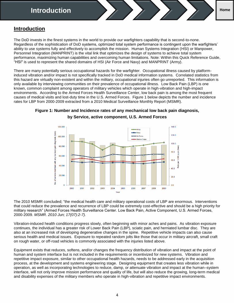
The DoD invests in the finest systems in the world to provide our warfighters capability that is second-to-none. Regardless of the sophistication of DoD systems, optimized total system performance is contingent upon the warfighters’ ability to use systems fully and effectively to accomplish the mission. Human Systems Integration (HSI) or Manpower, Personnel Integration (MANPRINT) is the vital link that optimizes the design of systems to achieve total system performance, maximizing human capabilities and overcoming human limitations. Note: Within this Quick Reference Guide, “HSI" is used to represent the shared domains of HSI (Air Force and Navy) and MANPRINT (Army). There are many potentially serious occupational hazards for the warfighter. Occupational illness caused by platform-induced vibration and/or impact is not specifically tracked in DoD medical information systems. Correlated statistics from this hazard are virtually non-existent and within the military, occupational injuries often go unreported. This information is only available by interviewing communities on their prevalence of occupational illness. Low Back Pain (LBP) is one known, common complaint among operators of military vehicles which operate in high-vibration and high-impact environments. According to the Armed Forces Health Surveillance Center, low back pain is among the most frequent causes of medical visits and lost-duty time in the U.S. Armed Forces. Figure 1 below depicts the number and incidence rates for LBP from 2000-2009 extracted from a 2010 Medical Surveillance Monthly Report (MSMR).
Figure 1: Number and Incidence rates of any mechanical low back pain diagnosis,
by Service, active component, U.S. Armed Forces
The 2010 MSMR concluded; “the medical health care and military operational costs of LBP are enormous. Interventions that could reduce the prevalence and recurrence of LBP could be extremely cost-effective and should be a high priority for military research” (Armed Forces Health Surveillance Center. Low Back Pain, Active Component, U.S. Armed Forces, 2000-2009. MSMR. 2010 Jun; 17(07):2-7). Vibration-induced health conditions progress slowly, often beginning with minor aches and pains. As vibration exposure continues, the individual has a greater risk of Lower Back Pain (LBP), sciatic pain, and herniated lumbar disc. They are also at an increased risk of developing degenerative changes in the spine. Repetitive vehicle impacts can also cause serious health and medical issues. Exposure to repeated random jolts like those that occur in military aircraft, small craft on rough water, or off-road vehicles is commonly associated with the injuries listed above. Equipment exists that reduces, softens, and/or changes the frequency distribution of vibration and impact at the point of human and system interface but is not included in the requirements or incentivized for new systems. Vibration and repetitive impact exposure, similar to other occupational health hazards, needs to be addressed early in the acquisition process, at the development and systems engineering stage. Designing equipment that creates less vibration while in operation, as well as incorporating technologies to reduce, damp, or attenuate vibration and impact at the human–system interface, will not only improve mission performance and quality of life, but will also reduce the growing, long-term medical and disability expenses of the military members who operate in high-vibration and repetitive impact environments.
Introduction Home

5
Purpose The Quick Reference Guide (QRG) is a job aid for the acquisition community (PMs, engineers, requirements officers, using organizations, IPTs, etc.). The goal for the QRG is to effect an overall reduction in warfighter Whole-Body Vibration (WBV) and/or repetitive impact exposure in military vehicles and reduce the health issues associated with this exposure by recommending HSI language to be included in key acquisition documents. The operation of the Defense Acquisition System (DAS), outlined in Department of Defense Instruction (DoDI) 5000.02, includes, among other things, the general procedures for the acquisition system, systems engineering, and Human Systems Integration (HSI). The Program Manager (PM) is required to address these issues:
“The PM shall ensure that appropriate HSI and Environmental, Safety and Occupational Health (ESOH) efforts are integrated across disciplines and into systems engineering to determine system design characteristics that can minimize the risks of acute or chronic illness, disability, death or injury to operators and maintainers; and enhance job performance and productivity of the personnel who operate, maintain, or support the system” (DoDI 5000.02, p.61).
Each of the Services has additional requirements/guidance on incorporating HSI to support system/user performance characteristics and combat readiness. The first and likely most effective way to reduce warfighter exposure to WBV and/or repetitive impact loads is early in the system design and development process. The QRG provides its users with model language (examples/guidance) for key documents throughout the system’s development life-cycle. This example language is a starting point from which language appropriate for the users’ programs or applications can be “tailored.”
Key Concept for WBV and/or Repetitive Impact Reduction within the QRG
Requirements Management & Traceability Requirements traceability captures and maintains the relationships among requirements, design, test, and implementation of a system. It is a significant part of the requirements management process and is critically important when addressing a Human Systems Integration (HSI) consideration and system attribute (such as WBV and repetitive impact exposure in DoD vehicles). The documents and artifacts selected for this QRG, and the model language provided for them, are intended to consistently highlight the importance of requirements management and traceability.
DISCLAIMER: This Quick Reference Guide (QRG) provides sample language/example requirements for a variety of roles and
missions. By design, the statements and sample language are written as generic templates, with blanks that would either need
to be completed or modified significantly, in order to make the statements meaningful or applicable. Program teams need to
review available guidance, lessons learned, and program specific details to determine relevance and applicability to their
program.
This QRG is intended to provide a starting point for tailoring language for individual development programs or applications. The
guidance provided and/or cited, as well as the language and statement examples given, do not necessarily reflect the views or
opinions of the developing organizations of this guide, and should not be interpreted as actual recommendations for action or as
existing requirements relevant to any development system or program.
DO NOT CITE THIS DOCUMENT AS A REQUIREMENT
6
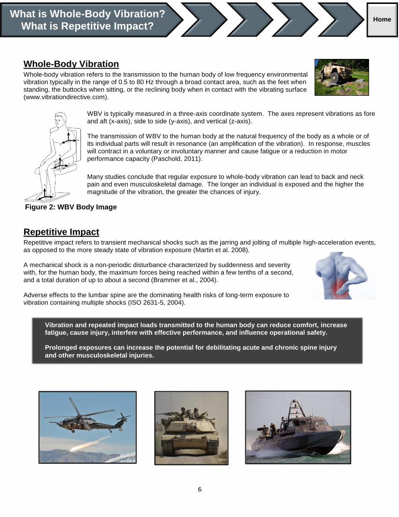
Whole-Body Vibration Whole-body vibration refers to the transmission to the human body of low frequency environmental vibration typically in the range of 0.5 to 80 Hz through a broad contact area, such as the feet when standing, the buttocks when sitting, or the reclining body when in contact with the vibrating surface (www.vibrationdirective.com).
WBV is typically measured in a three-axis coordinate system. The axes represent vibrations as fore and aft (x-axis), side to side (y-axis), and vertical (z-axis). The transmission of WBV to the human body at the natural frequency of the body as a whole or of its individual parts will result in resonance (an amplification of the vibration). In response, muscles will contract in a voluntary or involuntary manner and cause fatigue or a reduction in motor performance capacity (Paschold, 2011).
Many studies conclude that regular exposure to whole-body vibration can lead to back and neck pain and even musculoskeletal damage. The longer an individual is exposed and the higher the magnitude of the vibration, the greater the chances of injury.
Repetitive Impact Repetitive impact refers to transient mechanical shocks such as the jarring and jolting of multiple high-acceleration events, as opposed to the more steady state of vibration exposure (Martin et al. 2008). A mechanical shock is a non-periodic disturbance characterized by suddenness and severity with, for the human body, the maximum forces being reached within a few tenths of a second, and a total duration of up to about a second (Brammer et al., 2004). Adverse effects to the lumbar spine are the dominating health risks of long-term exposure to vibration containing multiple shocks (ISO 2631-5, 2004).
What is Whole-Body Vibration?
What is Repetitive Impact? Home
Vibration and repeated impact loads transmitted to the human body can reduce comfort, increase fatigue, cause injury, interfere with effective performance, and influence operational safety. Prolonged exposures can increase the potential for debilitating acute and chronic spine injury
and other musculoskeletal injuries.
Figure 2: WBV Body Image

7
Examples of Whole-Body Vibration (WBV) and Repetitive Impact in DoD Vehicles
Air (rotorcraft, propeller aircraft, jet aircraft)
Undesirable vibration and high vibration levels exist primarily in helicopters and propeller aircraft. The main sources of vibration in these types of aircraft include harmonic vibrations induced by the propeller or rotor, engine and gearbox operation plus structural vibrations caused by unstable aerodynamics (www.vibrationdirective.com). The vibration energy transferred through the aircraft structure creates an uncomfortable and potentially unsafe environment for aircrews. Vibration energy is typically transferred to a person's body through aircraft seating systems, flight controls, or the floor. Vibrations of different frequencies can affect the crewmember’s whole body or specific particular organs. For example, vision can be degraded due to vibration in the aircraft (shaking instruments may also be difficult to read). Continuous exposure to repetitive vibrations transferred through helicopter seats can:
Exacerbate pain and strain associated with poor flight posture of crewmembers
Accelerate fatigue and decrease situational awareness
Impact mission performance and operational safety
Generally cause both short and long-term occupational health issues/injuries
Land (tracked vehicles, light tactical vehicles, all-terrain vehicles, construction/logistics vehicles)
WBV is caused in land vehicles when shaking or jolting of the human body occurs through a supporting surface, usually a seat or the floor. The vibration can be produced by the vehicle itself (mechanical vibration) as well as by operation of a vehicle along rough roads or off-road (www.vibrationdirective.com). The U.S. Army typically evaluates the ride dynamics (or ride quality) and whole body vibration of select ground vehicles. The techniques used for evaluating the ride dynamics and WBV nominally involve the use of instrumented seats occupied by the vehicle crew.
Sea/Water (High-Speed Craft (HSC), Rigid Inflatable Boats (RIB)
WBV on RIBs and HSCs is usually caused by continuous “hammering” from short steep seas or wind against tide conditions. Repeated impact/shock on RIBs and High Speed Craft is primarily caused by random “hits” or “wave slams” from sea surface impacts (www.vibrationdirective.com). Occupants of U. S. Special Operations high-speed craft are exposed to severe and repeated shock loads during operation in heavy seas, leading to an alarming incidence of reported chronic and acute musculoskeletal injuries. Unlike their high-speed pleasure craft and offshore racing counterparts, military crewmembers must operate their craft at high speed in rough seas to fulfill their mission and, at times, to survive (Peterson, et al., 2004).

8
Existing Guidance for WBV and Repetitive Impact in DoD Vehicles
Standards Introduction:
MIL-STD-1472G; Design Criteria Standard; Human Engineering (11 JAN 2012) (Primary Standard/Reference for DoD system vibration and shock)
Section 5.5.5., Vibration and shock of this Military Standard requires that: “Vehicles for use on land, sea, or air shall be designed to control the transmission of whole-body vibration to levels that will permit safe and effective operation and maintenance. These vehicles include, but are not limited to, heavy ground vehicles, ATVs, trucks, aircraft, high speed boats, and ships.”
Section 5.5.5.1, Vehicular whole-body vibration explains: “The anticipated operational dynamic environment and exposure duration is required to determine the analysis method and threshold for whole-body vibration or shock.” The below table “defines environment categories expected to occur during operation of military vehicles. For each category, the exposure duration determines the exposure threshold” related to likelihood of health impacts.
Table 1: WBV Environment & Exposure Threshold
Environment
Category Description of Environment
A The environment is classified as strictly vibration and can be characterized as oscillatory in nature (periodic).
B The environment is classified as predominantly vibration and can be characterized as oscillatory in nature (periodic) but also contains occasional shocks or transient vibration (aperiodic).
C The environment may contain some underlying vibration, but is dominated by repeated or multiple shocks or transient vibration.
Figure 3 (extracted from MIL-STD-1472G, Section 5.5.5.1), demonstrate how the combination of both magnitude of the accelerations and the duration of exposure determine the risk zones for health impacts.
Figure 3: Health Guidance Zones for Limited Exposures

9
The Standard continues: “In an effort to minimize or prevent adverse health effects or injury, the vehicle design shall be in accordance with the following requirements for each of the operational environment categories.” Each environment category is further defined and “shall not exceed” values are given for each category (thresholds for health risk zones). MIL-STD-1472G provides guidance for the “evaluation” of the environment categories above by referencing ISO 2631, stating: “Evaluation of military vehicle vibration and its possible effects on health, performance, comfort, perception, and motion sickness shall be in accordance with ISO 2631 and associated amendments.”
Mechanical vibration and shock-Evaluation of human exposure to whole-body vibration-Part 1: General Requirements (ISO 2631-1; 1997)
(Referred to by MIL-STD-1472G for evaluation guidance of primarily Category A and B environments)
Mechanical vibration and shock-Evaluation of human exposure to whole-body vibration-Part 5: Method for evaluation of vibration containing multiple shocks (ISO 2631-5: 2004)
(Referred to by MIL-STD-1472G for evaluation guidance of primarily Category C environments)
NOTE: There are other related/associated Standards and References on this topic. The above summary is included here only to provide an introduction or “top-level” view to the direct guidance for DoD vehicle development, specific to whole-body vibration and repetitive impact exposure. Gaining a thorough understanding of MIL-STD-1472G and its references is a critical first step to efforts to reduce WBV and/or repetitive impact exposure in military vehicles. For other related Standards and References, see the Standards and References sections of the QRG.

10
DOTmLPF-P Change Recommendation (DCR)
The suggestions, example language provided, and the placement of the language within the document(s) are presented as a reference for acquisition and other professionals. Examples are not necessarily meant to be specific for any particular type of system or acquisition program. Suggestions and examples provided are intended to assist acquisition professionals by providing a starting point for tailoring language unique to
individual development programs. Specific standards can be obtained from an HSI practitioner or from any of the sources identified in the Standards and/or References tab. DOTmLPF-P = Doctrine, Organization, Training, materiel, Leadership and education, Personnel, Facilities, and Policy
A DCR (or Joint DCR) is a recommendation for changes to existing joint resources when such changes are not associated with a new defense acquisition program. A Joint DCR is a JCIDS-produced document that intents to partially or wholly address an identified capability requirement and associated capability gap with a non-materiel solution, recommending changes to existing capabilities of the Joint force in one or more of the DOTmLPF-P areas.
DOTmLPF-P analysis is the first step in the Functional Solutions Analysis (FSA). It determines/recommends if a non-material approach or a materiel approach is required to fill a capability gap identified in the Functional Needs Analysis (FNA). It includes the entire life cycle, including the sustainment; Environment, Safety, and Occupational Health (ESOH); and all Human Systems Integration (HSI) domains.
These items directly address:
Alternative Doctrinal Approaches and Alternative CONOPs
Policy and Personnel Alternatives
Changes to existing materiel or facilities
Adoption of other services’ / agency materiel or acquiring foreign materiel
There are two ways a Joint DCR is generated:
In conjunction with an ICD: as a non-materiel solution to a previously validated capability requirement and capability gap, or a non-materiel solution is identified as a complement to a materiel capability solution. The DCR will come first in case there are any non-materiel recommendations to fill the capability gap.
Without an ICD: if a non-materiel approach is the most viable solution.
DCR Model Language for Whole-Body Vibration (WBV) and/or Repetitive Impact This section provides model language (examples/statements) to address WBV and/or repetitive impact. Information in the form of Section Notes or Guidance may be provided which is generally applicable to the DCR Section identified. These sections may include Example Tables or other information (with WBV / Impact examples), presented in an DCR-representative format. The examples and formats provided will vary, in order to present the user with broad options and a general starting point for a DCR intended to incorporate WBV and/or repetitive impact as an important attribute(s). The user of this Guide is reminded that the information provided is intended to assist in “crafting” or “tailoring” language most appropriate to their particular program or set of circumstances, not to be a direct “cut-and-paste” solution.
- KEY -
<…> “Insert Applicable Information Here” (i.e. <x>, <X>, <Y>, <Z>, etc.)
<name, value, other>… Same as above with category / example of information needed
6._._.G-x Placeholder: example “unique identifier” for model language
DOTmLPF-P Change
Recommendation (DCR) Home

11
Table 2: DCR Section
Document Section Section Notes / Guidance
DCR Section 2
(Background)
or
“Alternate” DCR Format
Section 1
(Operational Context)
The purpose of this section is to provide context for the DOTmLPF-P change recommendations addressed by the Joint DCR and to provide appropriate traceability to the assigned missions, OPLANs/CONPLANs, CONOPS, etc., and other driving factors for the change recommendations. This information facilitates review and validation of the Joint DCR from the standpoint of how the change recommendations address or enable solutions to validated capability requirements and contribute to the overarching missions and activities of the Joint force.
Document Section Example Language
DCR Section 2
(Background)
or
“Alternate” DCR Format
Section 1
(Operational Context)
Discussion: <existing systems> are currently utilized in environments (extreme terrains) in which the crew systems were not intended or designed to support (creating ride environments and harmful exposures beyond human physical limitations for safety, health, performance, comfort; IAW MIL-STD-1472G, MIL-STD-882E); adapted mission profiles outside original system employment CONOPS, OPLANS/CONPLANS within Area of Responsibility (AOR).
Discussion: <existing systems> are consistently utilized in extreme environments for durations in which the crew systems (seat ergonomics, seat support, seat padding, seat vibration/impact damping) were not intended for or designed to support (creating ride environments and exposures beyond human physical limitations for safety, health, performance, comfort; IAW MIL-STD-1472G, MIL-STD-882E); adapted mission profiles outside original system employment CONOPS, OPLANS/CONPLANS within AOR).
In the absence of new systems designed to and which meet safety and occupational health standards for crew/passengers (specifically, exposure to constant whole-body vibration, or to repetitive impact (shock)), this DCR recommends DOTmLPF-P changes involving legacy system employment CONOPS, Training, Personnel, and non-acquisition materiel solutions to address the human constraint regarding overexposure to whole-body vibration and/or repetitive impacts in <existing x, legacy systems, vehicles>
This Joint DCR highlights the potential solutions to meet existing capability requirements, while improving <ESOH factors, WBV and/or repetitive impact (shock) environment> for crewmembers (existing capability gap due to human constraint); through changes to system employment CONOPS or OPLANS/CONPLANS, operations crew rotation schedule, as well as providing additional safety training and preventive physical fitness training to mission personnel. This DCR is structured to reduce to the safety and occupational health issues and injuries arising from exposure to whole-body vibration and/or repetitive impacts loads in <x systems, vehicles, etc.>, in lieu of major system-capability redesign and/or acquisition program.

12
Document Section Section Notes / Guidance
DCR Section 5
or
“Alternate” DCR Format
Section 4
(Change Recommendations and Implementation Plans)
The Joint DCR Findings and Proposed Implementation Plan section is decomposed into each DOTmLPF-P category. HSI and ESOH inputs <WBV, repetitive impact considerations> should be included in each category where appropriate. Because many of the HSI domains correspond to the DOTmLPF categories, the pertinent HSI domain considerations and implications can be identified.
DCR Section 5
Or
“Alternate” DCR Format
Section 4
(Change Recommendations and Implementation Plans)
Doctrine: The doctrine analysis examines the way the military fights conflicts with emphasizes on maneuver warfare and combined air-ground campaigns to see if there is a better way that might solve a capability gap.
• Is there existing doctrine that addresses or relates to the business need? • Is it Joint? Service? Agency?
Are there operating procedures in place that are NOT being followed which contribute to the identified need?
Organization: The organization analysis examines how we are organized to fight; divisions, air wings, Marine-Air Ground Task Forces, and others. It looks to see if there is a better organizational structure or capability that can be developed to solve a capability gap.
• Where is the problem occurring? What organization(s) is/are the problem occurring in?
• Is the organization properly staffed and funded to deal with the issue?
Training: The training analysis examines how we prepare our forces to fight tactically from basic training, advanced individual training, various types of unit training, joint exercises, and other ways to see if improvement can be made to offset capability gaps.
Is the issue caused, at least in part, by a complete lack of or inadequate training?
Does training exist which addresses the issue?
Materiel: The materiel analysis examines all the necessary equipment and systems that are needed by our forces to fight and operate effectively and if new systems are needed to fill a capability gap. Is the issue caused, at least in part, by inadequate systems or equipment?
For new systems and equipment, vibration may be best attenuated by vehicle and seating system design. Legacy systems may have the potential for vibration attenuation through improvements in seating design/modifications and stringent maintenance practices. Both new and legacy systems should integrate maintenance procedures that optimize control/mitigation of vibration and other factors that degrade personnel performance, readiness, comfort, and cause injury.
Leadership and Education: The leadership and education analysis examines how we prepare our leaders to lead the fight from squad leader to 4-star general/admiral and their overall professional development.
Does leadership understand the scope of the problem?
Does leadership have resources at its disposal to correct the issue?
Personnel: The personnel analysis examines availability of qualified people for peacetime, wartime, and various contingency operations to support a capability gap by restructuring.
Is the issue caused, at least in part, by inability or decreased ability to place qualified and trained personnel in the correct occupational specialties?
Are the right personnel in the right positions (skill set match)?
Policy: Any DOD, interagency or international policy issues that may prevent effective implementation of changes in the other seven DOTMLPF-P elemental areas. When the capability gap has significant user implications, HSI and ESOH language should be included in the policy section if current policy does not accurately or effectively define roles and responsibilities. Finally, when creating the recommendations summary section, there is the opportunity for general HSI and ESOH language as a reminder to consider the human impacts.

13
Document Section Example Language
DCR Section 5
Or
“Alternate” DCR Format
Section 4
(Change Recommendations and Implementation Plans)
Doctrine, Organization (Discussion/Recommendations):
Limit mission duration (ops and training) to reduce <Root Mean Square (RMS) vibration exposure, Vibration Dose Value (VDV), Sed values, etc.> and related mission performance degradation, fatigue and related safety impact.
Limit mission duration (ops and training) to reduce repetitive impact/shock exposure for warfighter.
Instill more conservative mission go/no-go parameters/system use-cases (ops and training).
Adjust COPLANS, CONPLANS, CONOPS (for system employment); limiting or restricting use-cases, mission environments, and mission durations.
Include WBV and repetitive impact exposure considerations when conducting Operational Risk Management (ORM).
Organization – Increase operator personnel allotment (crews available per system) to units/AORs to mitigate safety, health and performance risks (operating outside Safety and Occupational Health safe zones) associated with operations of <existing system; when operations require extended durations>
Establish crew rotation schedule to reduce single-crew mission durations to within safe ESOH ranges (WBV and repetitive impact exposure levels, for <system>)
Establish mission duration limits for crewmembers based on environmental/operational conditions due to occupational health hazard exposure safe zones for <WBV, impacts or shock loads> within <existing system>.
Establish more stringent go/no-go criteria for single-crew missions based on environmental conditions/operating conditions and realistic expectations of mission duration requirements, for <system>.
Limit training scenarios and system employment and duration of training for <system x>; to <z environments> to reduce individual exposure to WBV and repetitive impacts.
Limit operational mission environments to <x conditions, e.g. less severe conditions/terrains, other parameters>.
DCR Section 5
Or
“Alternate” DCR Format
Section 4
(Change Recommendations and Implementation Plans)
Training, Personnel (Discussion/Recommendations):
Training – Train operators on proper sitting and posture for operations. Training – Train operators to properly adjust the seats and properly adjusting the
restraints for good seating position and posture where <seat x or suspension seat x> is fitted, for the <crew, occupant> weight, especially when different people operate the vehicle.
Training – Identify and train on vehicles or machines in situations with the highest levels of vibration or impact. Arrange a schedule rotation for operators to reduce the time spent in training by individual operators.
Training – Train on planning routes with the smoothest terrain if possible, improving the ground surface over which vehicles have to be driven regularly.
Training – Establish more conservative training environments and training scenarios using/operating the <existing system> (lower risk conditions); limiting amount of training accomplished in the harshest condition to those absolutely operationally necessary (those which exceed ESOH considerations/standards- such as exposure to WBV or excessive exposure to repetitive impact shock. Example: operating water craft at excessive speeds and durations for harsh sea surface conditions).
Training – Establish a physical fitness training program for <system> operators; focusing on core strength exercises and other preventative and preparatory measures for exposure to WBV and/or repetitive impact environments associated with <system>.
Personnel – Add operator personnel (crews available per system) to mitigate safety, health and performance risks (operating outside Safety and Occupational Health safe zones) associated with operations of <existing system> for <x> extended durations.

14
Document Section Example Language
DCR Section 5
Or
“Alternate” DCR Format
Section 4
(Change Recommendations and Implementation Plans)
Materiel (the “little m”) (Discussion/Recommendations):
Evaluate Commercial Off-The-Shelf (COTS)/Commercial and Non-Developmental Items (CaNDI) seat appliances-support/padding systems with posture improvement technology and vibration isolation/damping technology.
Evaluate Commercial Off-The-Shelf (COTS)/Commercial and Non-Developmental Items (CaNDI) suspension seats appliances- support/padding systems with posture improvement and shock isolation/damping capability.
Seek improvements for crew station systems - ergonomics (improved posture, improved support, active/passive vibration isolation, damping, etc.).
Seek replacement seating pads with vibration damping and improved posture support (exiting technology, add-on, no system modification, mini-acquisition by platform)
Deploy COTS/CANDI replacement seat padding with posture improvement and vibration damping technology to <existing systems>.
Deploy posture improvement padding to existing seats in <systems>. Deploy or modify; vibration isolation technologies to seating system interfaces in
<existing system and existing seats>. Deploy or modify; vibration damping technology/capability to seating system
interfaces and replacement seating padding in <existing system and existing seats>.
Deploy or modify; suspension seating systems in <existing systems>. Deploy or modify; impact isolation/mitigation seating systems in <existing systems>. Utilize Engineering Change Proposal (ECP) process in <ongoing acquisition
program, other program>. Utilize ECP during scheduled Depot schedule/rotation. Incorporate <WBV, Impact Reduction technologies-requirements> into Service
and platform-specific Recapitalization program, Service Life Extension Programs (SLEP), Block Upgrade programs, pre-planned product improvements, <other program/process>.
Utilize Service Modification Programs: incorporate corrections by DoD Component through Service-specific Modification Proposals or similar processes for fielded systems (e.g. USAF Form 1067 Modification Proposal process).
USAF, AFI 63-131 Modification Management Program USAF, AF Form 1067 Process USAF, AFI 10-601, Chapter 8 USN, SECNAVINST 5000.2E USN, SECNAVINST 4855.5 Product Quality Deficiency Report (PQDR) USN Product Data Reporting and Evaluation Program (PDREP) USA, AR 750-10, Army Modification Program USA, AR 702–7–1, Reporting of Product Quality Deficiencies USA, AFR 74-6, Product Quality Deficiency Report Program
Include WBV/impact considerations in Requirements Correlation Table (RCT) in the analysis of alternatives (AoA); to summarize WBV and/or repetitive impact exposure reduction <techniques, technology, system design> as key capability that requires further development during the Technology Development phase of <programs>.

15
Document Section Example Language
DCR Section 5
Or
“Alternate” DCR Format
Section 4
(Change Recommendations and Implementation Plans)
Leadership and education, Training (Discussion/Recommendations):
Train Leadership and Operations personnel about WBV, the risks (safety, injury, comfort) and what they can do to prevent or reduce risks.
Educate and train Leadership and Operations personnel (incl. crewmembers) on hazards/risks of exposure to WBV and/or repetitive impacts/shock (magnitudes, durations) associated with operation of <system>.
Establish crew rotation schedule to reduce single-crew mission durations to within safe ESOH ranges (WBV and repetitive impact exposure levels, for <system>).
Training - Improve physical fitness programs for crews (preventive fitness training) for extended WBV exposure and/or repetitive impact exposures.
Identifying the vehicles/platforms and situations with the highest levels of vibration or impact and arranging a rotation for operators to reduce the time spent by individuals in the environment.
Implement planning routes with the smoothest terrain possible, improving the ground surfaces over which vehicles have to be driven regularly.
Establish more comprehensive training for operations personnel (leadership/commanders) and crewmembers on the hazards/risk of exposure to whole-body vibration (magnitude-durations) associated with operation of <system>; include training on health safe zones and durations, performance degradation and fatigue, need for safety and occupational health feedback in the military medical community.
Training, Leadership and Education - Establish more comprehensive training for operations personnel (leadership/commanders) and crewmembers training on the hazards/risks of exposure to repetitive impacts/shock (magnitudes, durations) associated with operation of <system>; include training on safe operating zones, fatigue and performance degradation factors, and the importance of reporting/feedback on injury.
DCR Section 5
Or
“Alternate” DCR Format
Section 4
(Change Recommendations and Implementation Plans)
Training, Policy (Medical community) (Discussion/Recommendations):
Establish epidemiological studies through the military medical community and laboratories (to better define characterize the problem, causal relationships, dose-response, occupational health issues, safety and total system performance) for military vehicles (air, land, sea) related to whole-body vibration and repetitive impact (shock) exposure; correlate results with Total Ownership Cost (TOC) of <existing system(s)> and potential TOC for follow-on, like-systems.
Each cognizant medical command collaborate with and assist the employing command in providing health education and lifestyle modification information to individuals with Work-related Muscular-Skeletal Disorder (WMSD) symptoms and for all identified workers at high risk for WMSDs.
Services encourage cognizant medical commands to offer medical care, advice, and counseling and physical therapy services to rehabilitate those with WMSDs. Where such services are not available from the cognizant medical command, activities may contract for physical therapy services, provided the cognizant medical command has an opportunity to review the procurement specification prior to solicitation and provide professional medical oversight of the contract.
Monitoring for Trends - Health care professionals should periodically, (e.g., monthly); review occupationally related acute care visits to monitor WMSD trends.
Policy (Discussion/Recommendations): Enforce adherence to existing standards for whole-body vibration and repetitive
impact (shock) exposure in <system x, existing systems and new acquisitions> as specified in MIL-STD-1472G.
Refine existing standards related to whole-body vibration and repetitive impact (shock) exposure based on research, measurement, and analysis (WBV and shock exposure; Ref MIL-STD-1472G and associated amendments and references).

16
Table 3: Other Considerations, Issues, and Lessons Learned for the DCR
Human Systems Integration (HSI)
Considerations 1. Is there a need to budget for HSI organizational activities with this capability? 2. Does the budget consider system design/ configuration to support material improvements,
including those required to ensure mission performance, related habitability (e.g. noise and/or vibration control)?
3. How will the DOTmLPF-P recommendations impact the domains of HSI? Will it force tradeoffs? 4. Are individuals appropriately qualified to support the needed capabilities? 5. With facility modification/development there may be human factors, manning, personnel,
training, and habitability implications (e.g., aircraft hangar, barracks, etc.). 6. Does the policy identify who is responsible for the human considerations regarding the
operations and use of a system or implementation of a process? 7. Any changes to the other DOTmLFP-P categories will affect the training category. Is that
accurately captured? 8. What are the human constraints and limitations (physical, emotional, cognitive)?
Issues 1. HSI currently fits into doctrine through the human performance (HP) construct, so language can be included to recommend review of doctrine to integrate verbiage on the effect on HP or on the specific HSI domains.
2. Consider the ability for the human to trust and embrace new ideas and technologies. 3. Need to create a common understanding of HSI across the services and different levels of
leadership.
Lessons Learned 1. Since the basis of doctrine can apply lessons learned - which dictate how the Armed Forces fight, HSI lessons learned can also be recommended for integration into the Joint Lessons Learned Program for the specific type of system or capability discussed in the DCR.
Environment, Safety, and Occupational Health (ESOH)
Considerations 1. Is there a need to budget for ESOH organizational activities with this capability? 2. A DCR could have occupational health or environment implications if it were recommending an
increase in activity for a particular group of individuals or at a specific location and/or along a specific route.
3. A DCR that affects facilities should be assessed to determine if environment-related recommendations are needed. For example, a DCR impacting known locations that are home to endangered species could include a recommendation to evaluate existing National Environmental Policy Act (NEPA) assessments to determine if the change will require new or different actions.
4. A DCR that affects facilities may have the potential to impact occupational-health, such as consideration of asbestos-containing buildings.
5. Will any of the DOTmLPF-P recommendations impact any aspects of ESOH?
Issues 1. A DCR could recommend a new or unique training, which would need to be evaluated to understand the system safety implications to identify potential new hazards and associated ESOH risks to personnel, equipment, or the environment.
Lessons Learned 1. ESOH is not currently called out in joint doctrine. Although it is unlikely that changes to Doctrine would affect the overall approach to safety, this safety-related input would be a practitioner’s focus.

17
Initial Capabilities Document (ICD)
The suggestions, example language provided, and the placement of the language within the document(s) are presented as a reference for acquisition and other professionals. Examples are not necessarily meant to be specific for any particular type of system or acquisition program. Suggestions and examples provided are intended to assist acquisition professionals by providing a starting point for tailoring language unique to
individual development programs. Specific standards can be obtained from an HSI practitioner or from any of the sources identified in the Standards and/or References tab. An ICD documents one or more new capability requirements and associated capability gaps. The ICD also documents the intent to partially or wholly address identified capability gap(s) with a non-materiel solution, materiel solution, or some combination of the two. The ICD is the most common starting point for new capability requirements (ICD Guide, 2012).
The ICD identifies a capability gap or other deficiency in terms of the functional area, the relevant range of military operations, and the timeframe. The ICD describes the evaluation of DOTmLPF-P approaches. Key Performance Parameters (KPPs) are not included in the ICD.
ICD Model Language for Whole-Body Vibration (WBV) and/or Repetitive Impact This section provides model language (examples / statements) to address WBV and/or repetitive impact. Information in the form of Section Notes or Guidance may be provided which is generally applicable to the ICD Section identified. These sections may include Example Tables or other information (with WBV / Impact examples), presented in an ICD-representative format. The examples and formats provided will vary in order to present the user with broad options and a general starting point for an ICD intended to incorporate WBV and/or repetitive impact as an important attribute(s). The user of this Guide is reminded that the information provided is intended to assist in “crafting” or “tailoring” language most appropriate to their particular program or set of circumstances, not to be a direct “cut-and-paste” solution.
- KEY -
<…> “Insert Applicable Information Here” (i.e. <x>, <X>, <Y>, <Z>, etc.)
<name, value, other>… Same as above with category / example of information needed
6._._.G-x Placeholder: example “unique identifier” for model language
Table 4: ICD Section
Document ICD Notes / Guidance
ICD
(General Guidance)
Example language below addresses <ESOH areas, incl. WBV and/or repetitive impact exposure> references that may be tailored/used when developing ICDs. ESOH issues may be addressed in the context of capability gaps (ICD Section 4) where present systems fail to adequately protect the mission or operators in terms of their impact on threat and operational environment (ICD Section 5). Necessary ESOH capabilities may be described in functional analysis (ICD Section 6) and/or final recommendations (ICD Section 7).
Current ICDs are restricted in page count and therefore tend to be very “high level”. Example language for WBV and repetitive impact exposure (or general ESOH) within ICD sections is provided for consideration (i.e. “as-if” model with multiple example combinations).
Initial Capabilities Document (ICD)
Home

18
Document Section Section Notes / Guidance
No Section Notes / Guidance for this Section
Document Section Example Language
ICD Section 2 Joint Capability Areas
(JCAs)
Or
“Alternate” ICD Format
Section N/A
1. Force Support 1.2 Force Preparation 1.4 Health Readiness 1.4.1 Force Health Protection 1.4.1.1 Human Performance Enhancement JCA 1.4.1.1. Joint Human Performance Enhancement – The ability to extend physical and mental endurance and enhance physiological and psychological resilience to reduce future joint force injury and illness by enhancing physical resilience, physiological resilience, psychological resilience, reduced recovery time from injury, and reduced rates of injury and illnesses.
3. Force Application 3.1 Maneuver (by association with a broader system JCA at Tier I and II)
HSI considerations could be tied to broader capability requirement area addressed by the above JCA; include vehicle vibration or repetitive impact (exposure mitigation) in the above range of military operations as a capability attribute (see ICD section 3).
4. Logistics 4.1 Deployment and Distribution 4.4 Logistics Services (by association with a broader system JCA at Tier I and II) HSI considerations could be tied to broader a capability requirement area addressed by above JCA tiers; vehicle vibration or repetitive impact included in the above range of military operations as a capability attribute (see ICD section 3).
Document Section Section Notes / Guidance
ICD Section 3
Capability Requirements
Or
“Alternate” ICD Format Section 3
Capability Requirements and Gaps/Overlaps
Human-related implications identified in the Capabilities Based Assessment (CBA) should be mentioned in section 3.
Identifying human-touch points in the system emerging from the ICD sets key traceability hooks for capability requirements and key attributes refinement in follow-on documents: Capability Development Document (CDD), Capability Production Document (CPD), System Performance Specification (SPS) or System, Requirements Document (SRD), etc.)
Develop <WBV and/or repetitive impact, ESOH> constraints and performance attributes for the system.
Key Performance Parameters (KPPs) are not included in the ICD. Capabilities should address vulnerabilities and shortcomings of legacy systems.
Where feasible, attributes should be stated in terms that reflect the capabilities necessary to meet the military mission (or related support and sustainability) in the intended environment. These attributes should be measurable and testable. Requirements for operation in various climactic settings and operational environments should be described in a way that allows for a design that will support appropriate developmental and operational testing and evaluations.
Document Section Example Language
ICD Section 3 or
“Alternate” ICD Format Section 3
Capability Requirements and Gaps/Overlaps
The <system> will be designed to eliminate or mitigate safety, health or physical risks pertaining to whole-body vibration. Where hazards/risks exist, health and safety equipment and/or procedures should be identified. Health and Safety procedures and design considerations should conform to all pertinent standards. Crew task load, fatigue factors, operation environments, and data assimilation must be considered.
The system design will take advantage of advances in technology to improve total system performance inclusive of the human, hardware, and software pertaining to crew and passenger exposure to whole-body vibration or repetitive impacts.

19
Document Section Example Language
ICD Section 3
Capability Requirements
(Attributes and Outcomes)
Or
“Alternate” ICD Format Section 3
Capability Requirements and Gaps/Overlaps
The <system name> design will address <applicable HSI domains (Manpower, Personnel, Training, HFE, ESOH, Personnel Survivability, and Habitability), whole-body vibration and exposure to repetitive impact loads> within the system.
The <system name> will be designed to accommodate the characteristics of the user population that will operate, maintain, and support the system, optimize total system performance, and minimize total operational cost (expected KSA(s) in CDD for crew systems with Threshold, Objective value(s)).
<WBV/Impact> will be identified, eliminated, minimized, or controlled to acceptable levels within cost, schedule, and performance constraints. Implement whole-body vibration and/or repetitive impact exposure mitigation/reduction technology and techniques to ensure crews and passengers are not exposed to hazardous levels of whole-body vibration or impact loads of expectant mission environments and durations (expected KSA development for crew systems/subsystems relative to <WBV/Impact exposure>).
The total vibratory environment of the <system, vehicle> will be such that compatibility between the <vehicle frame, chassis, structure>, engines, subsystems, and installed equipment is achieved and the ability of the <vehicle type>, its crew, and any passengers or troops to perform the required missions is not compromised.
Human factors vibration specifications will reflect the nature of the missions that the <vehicle> and its occupants shall perform. The allowable levels shall preclude vibration from reducing mission effectiveness. Consideration shall be given to the operations crew, and passengers and/or troops.

20
Document Section Example Language
ICD Section 3
Capability Requirements
(Attributes and Outcomes)
Or
“Alternate” ICD Format Section 3
Capability Requirements and Gaps/Overlaps
Crew Station:
The seat(s) shall promote good posture in the operational environment and for the duration of the mission (up to <x> hours) by; providing uniform body support over the seat/occupant contact area (not causing “hot spots” to occur), not transmitting vibrations to the occupant of <y> frequencies exceeding <z> amplitudes, and providing back support to reduce lumbar loads and back muscle fatigue.
<system, platform> will provide a fully integrated crew station enabling mission focused operations.
The crew station will be ergonomically designed to optimize crew interaction, minimize human error, and physical discomfort, and ensure safe operations.
The crew station will be designed to mitigate crew and passenger exposure to vehicle-induced and/or environment induced-transferred whole-body vibration to safe operating levels across <xx> mission environments (expected CDD KSA)
The crew station will be designed to mitigate crew and passenger exposure to vehicle-induced and/or environment transfer of repetitive impact/shock accelerations/loads to safe operating levels across <xx> mission environments, IAW existing standards (expected CDD KSA with Threshold value).
The crew station will be compatible with all warfighter worn Aviation Life Support Equipment (ALSE).
The crew station will be compatible with warfighter worn body armor, Night-Vision Goggles (NVGs), <other/etc.>.
The human-system interfaces of all vehicle concepts (Crew and passenger seating systems) will be designed to safely support crewmembers for extended mission durations (min <x> to <y> hours) as specified by <MIL-STD-1472, other> and applicable references or amendments.
The human-system interfaces of all vehicle concepts (crew and passenger seating systems) will be designed to support safe operation through mission durations of up to <value> hours through improved body posture/support mechanisms, mitigation-damping of transfer of vibration (system and environment) and/or transfer of repetitive impact energy (multiple shocks) Ref: MIL-STD-1472G, Section 5.5.5.; ISO 2631-1, ISO 2631-5.
Parameters to be reflected in the TEMP include whole-body vibration evaluation with attention to seating performance and control of system/equipment vibration and related maintainability.
Document Section Example Language
ICD Section 3
Capability Requirements
(Attributes and Outcomes)
Or
“Alternate” ICD Format Section 3
Capability Requirements and Gaps/Overlaps
The system will ensure the safety and survivability of the system and provide a safe, healthy, and efficient/comfortable environment for operators. Risk factors will be identified, tracked, and managed through a system safety program consistent with <X: i.e. MIL-STD-882E, MIL-STD-1472G, MIL-STD-46855A, etc.>.
For the system, safety considerations will be provided for in the program baseline to support sustainable operation and maintenance. Designs will be consistent with human factors engineering criteria per references <*, MIL-STD-46855A, MIL-STD-1472G> or equivalent standards. *Cite references and/or related criteria, as appropriate to the system under consideration.
Development of the system and design of support processes and materials will identify mishap risks associated with hazardous materials and minimize their human health, safety and environmental impacts through selection of the alternatives consistent with operational requirements, cost, and efficiency.
Manpower, training, and personnel costs will be minimized through task and process identification, design for efficiency, and use of automated processes and equipment, where feasible, to reduce life cycle costs and mishap risks.
Criteria for systems/equipment designs will utilize systems engineering and human systems integration (HSI) principles to ensure that designs are consistent with the capabilities and limitations of the anticipated users.

21
Document Section Example Language
ICD Section 3
Capability Requirements
(Attributes and Outcomes)
Or
“Alternate” ICD Format Section 3
Capability Requirements and Gaps/Overlaps
Identified safety and health risks will be eliminated, minimized, or controlled to acceptable levels within cost, schedule, and performance constraints as identified in MIL-STD-882E and shall be accomplished for the life of the system.
Crew and passenger whole-body vibration exposure shall be mitigated to safe levels across <xx> mission environments, for mission durations up to and including <value> hours (expected development of KSA for WBV) Ref: MIL-STD-1472G, Section 5.5.5., ISO 2631-1.
Crew and passenger exposure to repetitive vehicular impact loads (multiple shocks) will be mitigated to safe levels across <xx> mission environments, for mission durations up to and including <value> hours (expected CDD KSA with Threshold (T) and Objective (O) values). Ref: MIL-STD-1472G, Section 5.5.5., ISO 2631-5.
Mitigation of whole-body vibration and or repetitive impact exposure by design:
Vehicles for use on land, sea, or air shall be designed to control the transmission of whole-body vibration to levels that will permit safe and effective operation and maintenance. These vehicles include, but are not limited to, heavy ground vehicles, All Terrain Vehicles (ATVs), trucks, aircraft, high speed boats, and ships IAW MIL-STD-1472G).
The crew and passengers/troops shall not be exposed to vibrations which reduce their effectiveness or increase their workload while performing their required missions IAW MIL-STD-1472G, ADS-27.
The crew and passengers/troops shall not be exposed to individual or repeated jarring impacts which reduce their effectiveness or increase their workload while performing their required missions. (Army)
Document Section Section Notes / Guidance
ICD Section 3
Capability Requirements
Or
“Alternate” ICD Format Section
(Summary Table)
The ICD calls for a table summarizing the relationship between Joint Capability Areas (JCAs), capability requirements and relevant attributes, and their associated metrics and minimum values.
An example table with “representative” vibration and repetitive impact language is provided below (Table 5). The below table is roughly formatted according to ICD development guidance. See Table 5 at the end of the ICD section.
J
Document Section Section Notes / Guidance
ICD Section 4
Or
“Alternate” ICD Format Section 3
Describe the Capability Gaps: missions, tasks, and functions that cannot be performed or are unacceptably limited. The limitations of human performance should be included in this section.
Document Section Example Language
ICD Section 4
Or
“Alternate” ICD Format Section 3
Capability Requirements and Gaps/Overlaps
<legacy, existing system> seating systems were designed with priority to crashworthiness considerations and were not designed to support crewmembers effectively for mission durations of current employment CONOPS, OPLANS, CONPLANS, within CCMD AOR.
The human-system interface(s) of the <vehicle, existing system(s), seating systems> does not provide adequate <WBV, repetitive impact load> mitigation.
Legacy seating systems <and/or interfaces with controls> create poor posture within current operating environments and mission durations (including training environments).

22
Document Section Example Language
ICD Section 4
Capability Gaps
Or
“Alternate” ICD Format Section 3
Capability Requirements and Gaps/Overlaps
System-Producing Vibration and/or Impacts (shocks):
In all operating/employment environments, <existing system> produces excessive system (mechanical) vibration which is transferred to crew stations and crewmembers through human system interface (seats, floor, controls) Ref: MIL-STD-1472.
<existing systems> create and transfer excessive vibrational energy to crewmembers and passengers (above caution zone for <x> durations as specified by MIL-STD1472G; ISO 2631-1 and ISO 2631-5).
<existing systems> incapable of maintaining safe crew operations zones related to WBV transfer; <x> mission environments/profiles, <x> durations (IAW MIL-STD-1472G, Section 5.5.5., ISO 2631-1, MIL-STD-882E)
<existing systems> incapable of maintaining safe crew operations zones related to repeated impact loads/shock; ; <x> mission environments/profiles, <x> durations (IAW MIL-STD-1472G, Section 5.5.5., ISO 2631-5)
<existing systems> incapable of operating for <x hours> without exceeding safety and occupational health standards for crewmembers and passengers; whole-body vibration transfer <and/or repetitive impact loads>.
Environment-Induced Vibration and/or Impacts (shocks):
<existing systems> incapable of providing adequate postural support for crewmembers (crew stations, seats); inadequate mitigation of whole-body vibration transfer at human-system interfaces, and inadequate mitigation of repeated impact/shock energy transfer in <x> operating and training environments, for current use employment durations.
Rationale: Operator limitations; over-exposure to the health hazards associated with whole-body vibration <or repetitive impact loads> in <existing system>, negative impacts on operational capability (widening other operational capability gaps).
<existing systems> are consistently utilized in environments with extreme terrains or conditions for which the crew systems (seats, interfaces) were not necessarily designed to support. Operations environments are creating ride conditions with WBV and/or repetitive impact (multiple shock) exposures in excess of health risk safe zones (safety, health, performance, comfort; thresholds as specified in MIL-STD-1472G and associated Standards); adapted mission profiles outside original system employment <CONOPS, OPLANS, CONPLANs, within CCMD AOR>.
<existing systems> are utilized in extreme environments for durations in which the crew systems (seat ergonomics, seat support, seat padding, seat vibration/impact damping) were not intended for or designed to support (creating ride environments and exposures beyond human physical limitations for safety, health, performance, comfort; IAW MIL-STD-1472G, MIL-STD-882E); adapted mission profiles outside original system employment <CONOPS within CCMD AOR, other>.
Seating Systems, Crew Stations:
<existing systems> crew compartment support/seating systems inadequate in both posture control and whole-body vibration transfer for mission profiles within existing <OPLANS, CONPLANS, CONOPS, within CCMD AOR>.
<existing crew compartment systems, i.e. seats, supports, padding systems> inadequate in both posture support and whole-body vibration mitigation (excessive WBV transfer for mission profiles within existing system employment CONOPS, AOR)
<existing crew compartment systems, i.e. seats, suspended seats supports and padding systems> inadequate in both posture control and repetitive impact/shock energy/load transfer (excessive shock transfer for mission profiles within existing system employment CONOPS within AOR, including training scenarios).
<existing systems> lack the operator posture sustaining/support technology and vibration isolation/damping technology necessary to accomplish <XX> percent of mission profiles and durations defined in CONOPS and other plans.

23
Document Section Section Notes / Guidance
ICD Section 4
Capability Gaps
Or
“Alternate” ICD Format Section 3
Capability Requirements and Gaps/Overlaps
The ICD calls for a table summarizing Capability Gaps.
An example table with “representative” vibration and repetitive impact language is provided below (Table 6). The table is roughly formatted according to ICD development guidance. See Table 6 at the end of the ICD section.
J
Document Section Section Notes / Guidance
ICD Section 6/7
Ideas for Non-Materiel Approaches / Final Recommendations
Or
“Alternate” ICD Format Section 4/5
Assessment of Non-Materiel Approaches / Final Recommendations
Clearly differentiate which kind of DOTmLPF-P changes are necessary. Summarize results of DOTmLPF-P analysis (including WBV and/or repetitive impact
exposure, HSI considerations) - linked to capabilities requirements / gaps. Changes should be considered from two perspectives: - Enabling - changes that enable the implementation, operations and support of the
specific system - Integrating - changes that must be made to support integration of this system with
existing capability solutions. J For all capability requirements that cannot be met using non-materiel approaches,
make specific recommendations on the type of materiel approach preferred to close each capability gap (helps scope AoA).
See also DCR Section of this QRG for more DOTmLPF-P examples.
Document Section Example Language
ICD Section 6/7
Ideas for Non-Materiel Approaches / Final Recommendations
Or
“Alternate” ICD Format Section 4/5
Assessment of Non-Materiel Approaches / Final Recommendations
(DOTmLPF-P as part of materiel solution)
Enhancement of an Existing System: Analysis indicates <x number> of the capability gaps can be partially mitigated using materiel solutions. Recommend a Joint DOTmLPF-P Change Recommendation (DCR) that advocates addressing the following gaps/shortfalls:
Utilize <Service-specific process> for Modifications to/for fielded systems <e.g. USAF Form 1067 Modification Proposal process>.
Evaluate Commercial Off-The-Shelf (COTS)/Commercial and Non-Developmental Items (CaNDI) seat appliances-pads with posture improvement technology and vibration isolation/damping technology.
Evaluate Commercial Off-The-Shelf (COTS)/Commercial and Non-Developmental Items (CaNDI) suspension seats appliances-pads with posture improvement and support and shock isolation/damping.
Deploy replacement seat padding with posture improvement and vibration damping technology to <existing systems>.
Deploy posture improvement padding to existing seats in <systems>.
Deploy or modify; vibration isolation technology to seating system interfaces in <existing system and existing seats>.
Deploy or modify; vibration damping technology to seating system interfaces and replacement seating pads in <existing system and existing seats>.
Deploy or modify; suspension seating systems in <existing systems>.
Deploy or modify; impact isolation/mitigation seating systems in <existing systems>.

24
Document Section Example Language
ICD Section 6/7
Ideas for Non-Materiel Approaches / Final Recommendations
Or
“Alternate” ICD Format Section 4/5
Assessment of Non-Materiel Approaches / Final Recommendations
(DOTmLPF-P independent of materiel solution)
Replacement or Recapitalization of an Existing System:
Engineering Change Proposal (ECP) in ongoing acquisition program.
Incorporate requirements in <x system> Recapitalization program.
Incorporate requirements in <y system> Service Life Extension Program (SLEP).
Criteria for systems/equipment designs will utilize systems engineering and human systems integration (HSI) principles to ensure that designs are consistent with the capabilities and limitations of the anticipated users.
Seating and support systems for crew compartments of <existing system> will be upgraded through System Engineering process and verified in accordance with reference <x> (incorporating posture improvement technology, WBV mitigation and/or repetitive impact mitigation technologies to meet <x>).
New System, Concept:
<Blank> concludes that DoD must develop and produce a new family of future <capability> vehicles/platforms to satisfy capability gaps that exist within the <blank> today as well as future gaps documented from analysis of the <blank> concepts.
DOD must pursue materiel solutions to meet current and projected capability gaps for <capability> <with prioritized specified enhancements relative to human operator safety and occupational health>.
Any incremental or evolutionary approaches to meet needed capability gaps must include provisions to address enhancement or redesign of <system, capability> crew stations to correct deficiencies/shortfalls in Human Systems Integration considerations of <operator/passenger WBV and/or repetitive impact exposure, other ESOH> in performing current missions as well as meeting future mission requirements.
Further analysis is required to more narrowly focus the broad ranges of some performance parameters and should be carried out during the conduct of an Analysis of Alternatives (AoA).
Recommend a Joint DOTmLPF-P Change Recommendation (DCR) that advocates addressing the following gaps/shortfalls:
Enforce adherence to existing standards for whole-body vibration and repetitive impact (shock) exposure in <system(s)>; Ref: MIL-STD-1472.
Add operator personnel (crews available per system) to mitigate safety, health and performance risks (per individual).
Establish crew rotation schedule to reduce single-crew mission durations to within safe <WBV, impact> ranges for <system>.
Establish mission duration limits based on environmental conditions due to occupational health hazard exposure (WBV, impacts) within <existing system>.
Establish more stringent go/no-go criteria for single-crew missions based on environmental conditions/operating conditions mission duration requirements.
There are no non-materiel solutions that will mitigate the identified gaps. Procuring additional existing systems will not sufficiently mitigate identified gaps (or the <x> attributes/operational risks associated with identified gaps).

25
Document Section Example Language
ICD Section 6/7
Ideas for Non-Materiel Approaches / Final Recommendations
Or
“Alternate” ICD Format Section 4/5
Assessment of Non-Materiel Approaches / Final Recommendations
(DOTmLPF-P independent of materiel solution)
Recommend a Joint DOTmLPF-P Change Recommendation (DCR) that advocates
addressing the following training centric gaps/shortfalls:
It is not feasible to fully mitigate capability gaps through training changes. Although training is an essential enabler, capability gaps cannot be mitigated through changes to individual, crew, and collective training. It is noted that training consolidation may be a great benefit to all Services and is achievable through common <vehicle, system> solutions.
Establish more conservative training environments for <existing system> (lower risk conditions), limiting harshest the condition/highest safety, occupational health exposure/risk scenarios (limit extreme training environments).
Limit training scenarios and training employment duration of <system>; to <x hours, days per week> to reduce individual exposure to WBV and/or repetitive impact loads.
Establish comprehensive training for operations personnel (leadership/commanders) and crewmembers on the hazards/risk of exposure to whole-body vibration and repetitive impacts/shock (magnitude-durations) associated with operation of <system>; include training on health safe zones and durations, performance degradation and fatigue, need for safety and occupational health feedback in the military medical community.
Establish physical fitness training program for <system> operators; focus on core strength exercises and other preventative and preparatory measures for exposure to WBV and/or repetitive impact environments associated with <system>.
Other DOTmLFP-P examples:
There are no non-materiel solutions that will sufficiently mitigate the identified gaps, and the key or fundamental attributes of <system’s, legacy system’s> crew/occupant exposure to WBV and/or repetitive impact loads which must be addressed. Procuring additional existing systems will not mitigate identified gaps without major systems engineering effort focused on <system, crew systems- WBV and impact).
Further analysis is required to more narrowly focus the broad ranges of some performance parameters and should be carried out during the conduct of an AoA.
Further research efforts to acquire actual exposure measurements <mission data - WBV, repetitive impact> in operational environments for <system(s)>; correlate with standards, existing technologies, and new engineering approaches.
Recommend epidemiological studies through the military medical community and laboratories (better define causal relationships, dose-response, occupational health issues, safety and total system performance) for military vehicles and muscular-skeletal injury <related to whole-body vibration and repetitive impact>.
Continue to refine existing standards related to whole-body vibration and repetitive impact (shock) exposure based on research, above-mentioned measurement, and further analysis.
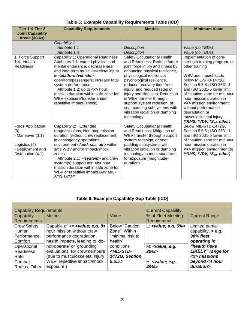
26
Table 5: Example Capability Requirements Table (ICD)
Tier 1 & Tier 2 Joint Capability
Areas (JCAs)
Capability Requirements Metrics Minimum Value
Capability 1
Attribute 1.1 Description Value (no TBDs)
Attribute 1.n Description Value (no TBDs)
1. Force Support 1.4. Health Readiness
Capability 1: Operational Readiness Attributes 1.1: extend physical and mental endurance; decrease near and long-term musculoskeletal injury in <platform/vehicle> operators/passengers; increase total system performance Attribute 1.2: up to <x> hour mission duration within safe zone for WBV exposure/transfer and/or repetitive impact (shock)
Safety Occupational Health and Readiness; Reduce future joint force injury and illness by enhancing physical resilience, physiological resilience, psychological resilience, reduced recovery time from injury, and reduced rates of injury and illnesses; Reduction in WBV transfer through support system redesign, or seat padding subsystems with vibration isolation or damping technology
Implementation of core-strength training program, or other training WBV and impact loads below MIL-STD-1472G, Section 5.5.5.; ISO 2631-1 and ISO 2631-5 lower limit of *caution zone for min <x> hour mission duration in <X> mission environment; without performance degradation or musculoskeletal injury (*RMS, *VDV, *Sed, other)
Force Application (3) - Maneuver (3.1) Logistics (4) - Deployment and Distribution (4.1)
Capability 2: Extended range/missions, Non-stop mission duration (without crew replacement) in contingency operations environment <land, sea, air> within safe WBV and/or impact/shock zones Attribute 2.1: <system> and crew system(s) support min <x> hour mission duration within safe zone for WBV or repetitive impact IAW MIL-STD-1472G.
Safety Occupational Health and Readiness; Mitigation of WBV transfer through support system redesign, or seat padding subsystems with vibration isolation or damping technology to meet standards for exposure (magnitude-duration)
Below MIL-STD-1472G, Section 5.5.5.; ISO 2631-1 and ISO 2631-5 lower limit of *caution zone for min <x> hour mission duration in <X> mission environment(s) (*RMS, *VDV, *Sed, other)
Table 6: Example Capability Gap Table (ICD)
Capability Requirements
Current Capability
Capability Requirements
Metrics Value % of Fleet Meeting Requirement
Current Range
Crew Safety, Human Performance, Comfort
Capable of <= <value; e.g. 8> hour mission without crew performance degradation, health impacts, leading to ‘do-not-operate’ or ’grounding’ evaluations for crewmembers (due to musculoskeletal injury WBV, repetitive impact/shock exposure,)
Below “Caution Zone”; Within “minimal risk to health” conditions <MIL-STD-1472G, Section 5.5.5.>
L: <value; e.g. 5%> Limited partial capability; < e.g. 90% fleet operating in “health risks LIKELY” range for <x> missions beyond <4 hour duration>
Operational Readiness Rate
M: <value; e.g. 20%>
Combat Radius, Other
H: <value; e.g. 40%>

27
Analysis of Alternatives (AoA)
The suggestions, example language provided, and the placement of the language within the document(s) are presented as a reference for acquisition and other professionals. Examples are not necessarily meant to be specific for any particular type of system or acquisition program. Suggestions and examples provided are intended to assist acquisition professionals by providing a starting point for tailoring language unique to
individual development programs. Specific standards can be obtained from an HSI practitioner or from any of the sources identified in the Standards and/or References tab. The AoA refines the selected materiel alternatives from an ICD(s) and/or Capabilities Based Analysis (CBA) that was done to augment existing ICD(s). An AoA is an analytical comparison of the operational effectiveness, cost, and risks of proposed materiel solutions to gaps and shortfalls in operational capability. AoAs document the rationale for identifying and recommending a preferred solution or solutions to the identified shortfall(s). Threat changes, deficiencies, advances in technology or the obsolescence of existing systems can trigger an AoA.
The AoA provides the analytic underpinning for Key Performance Parameters (KPP), initial draft Capabilities Development Document (CDD), preferred system concept, preliminary system specification and Measures of Effectiveness (MOE) that define system performance and trace back to the CBA/ICD.
The first major step leading to a successful AoA is the creation and coordination of a well-considered study plan. At a minimum, the study plan should facilitate full consideration of possible trade-offs among cost, schedule, and performance objectives for each alternative considered, as well as an assessment of whether or not the joint military requirement can be met in a manner that is consistent with the cost and schedule objectives.
AoA Model Language for Whole-Body Vibration (WBV) and/or Repetitive Impact This section provides model language (examples / statements) to address WBV and/or repetitive impact. Information in the form of Section Notes or Guidance may be provided which is generally applicable to the AoA Section identified. These sections may include Example Tables or other information (with WBV / Impact examples), presented in an AoA-representative format. The examples and formats provided will vary, in order to present the user with broad options and a general starting point for an AoA intended to incorporate WBV and/or repetitive impact as an important attribute(s). The user of this Guide is reminded that the information provided is intended to assist in “crafting” or “tailoring” language most appropriate to their particular program or set of circumstances, not to be a direct “cut-and-paste” solution.
- KEY -
<…> “Insert Applicable Information Here” (i.e. <x>, <X>, <Y>, <Z>, etc.)
<name, value, other>… Same as above with category / example of information needed
6._._.G-x Placeholder: example “unique identifier” for model language
Table 7: AoA Section
Document AoA Notes / Guidance
AoA,
AoA Study Plan
AoAs provide comparative cost, effectiveness, and risk assessments of proposed alternatives against a baseline, typically the current operating system (AFI 10-601).
AoA scenarios must portray realistic operational environments. A range of scenarios may be needed to investigate the full potential of the alternatives and their sensitivities to variations in constraints and assumptions, particularly with regard to threats (AFI 10-601).
Analysis of Alternatives (AoA)
Home

28
Document AoA Notes / Guidance
AoA,
AoA Study Plan
Regardless of the source, each constraint and assumption must be explicitly identified, checked for consistency with other constraints and assumptions, and then accounted for in the scope of the AoA.
Constraints and assumptions are the one area of the AoA that will come under special scrutiny. Every AoA is going to have its allies/supporters and its detractors, and this is one likely point of attack. It is critical that the team thoroughly document each constraint and assumption. The study will begin with an initial set of assumptions but this may grow as the study progresses. The initial set is documented in the study plan which is used to ensure that everyone understands the scope of the AoA (AoA Handbook).
Reference applicable sections of the ICD, CDD, or AoA guidance as appropriate.
AoA Planning and HSI Considerations: Identify <HSI – WBV, impact exposure> issues to be assessed for each alternative concept; metrics to enable assessment of the <HSI – WBV, impact exposure> issues; and expected results of the assessment. The overriding objectives of providing <HSI – WBV, impact exposure> inputs to the AoA planning are that an assessment will be made of: 1) The implications of each design alternative on human performance, workload,
survivability, health and safety, and quality of life 2) The extent to which the design alternative addresses manpower optimization
Document Section Section Notes / Guidance
No Notes / Guidance for this Section
Document Section Example Language
AoA Study Plan
Ground Rules
(Scope, Scenarios, Environment, Constraints
and Assumptions)
Identify risks for excessive or harmful exposure levels of <whole-body vibration or repetitive impact exposure> associated with each alternative system and amongst the various operations scenarios or use cases; document risks in a Preliminary Hazard List (PHL).
(The PHL is called up by Task 201 of MIL-STD-882E. The PHL provides a list of hazards that may require special safety design emphasis or hazardous areas where in-depth analyses need to be done. It is compiled very early in the system acquisition life cycle to identify potentially hazardous areas on which to put management emphasis).
(The PHL is the precursor to the Preliminary Hazard Analysis (PHA)).
Evaluate the <system concept, alternative> ability to meet performance capability requirements within identified <WBV and/or repetitive impact exposure, and other ESOH> constraints and risks.
Operating Environments: The anticipated operational dynamic environment and exposure duration is required to determine analysis methods and thresholds for whole-body vibration or repetitive impact (See MIL-STD-1472G for vibration environment categories and classifications for expected operation of military vehicles).
Constraint: crewmember (human) exposure to whole-body vibration or repetitive impact for given <alternative> is limited to non-hazardous, non-performance degrading levels (not to exceed <X, “low health risk” zone, “caution” zone, RMS values, VDV values, Sed values, etc.> for associated exposure durations, IAW MIL-STD-1472G, section 5.5.5, ISO 2631-1 and ISO 2631-5 (health hazard zones - threshold limits).
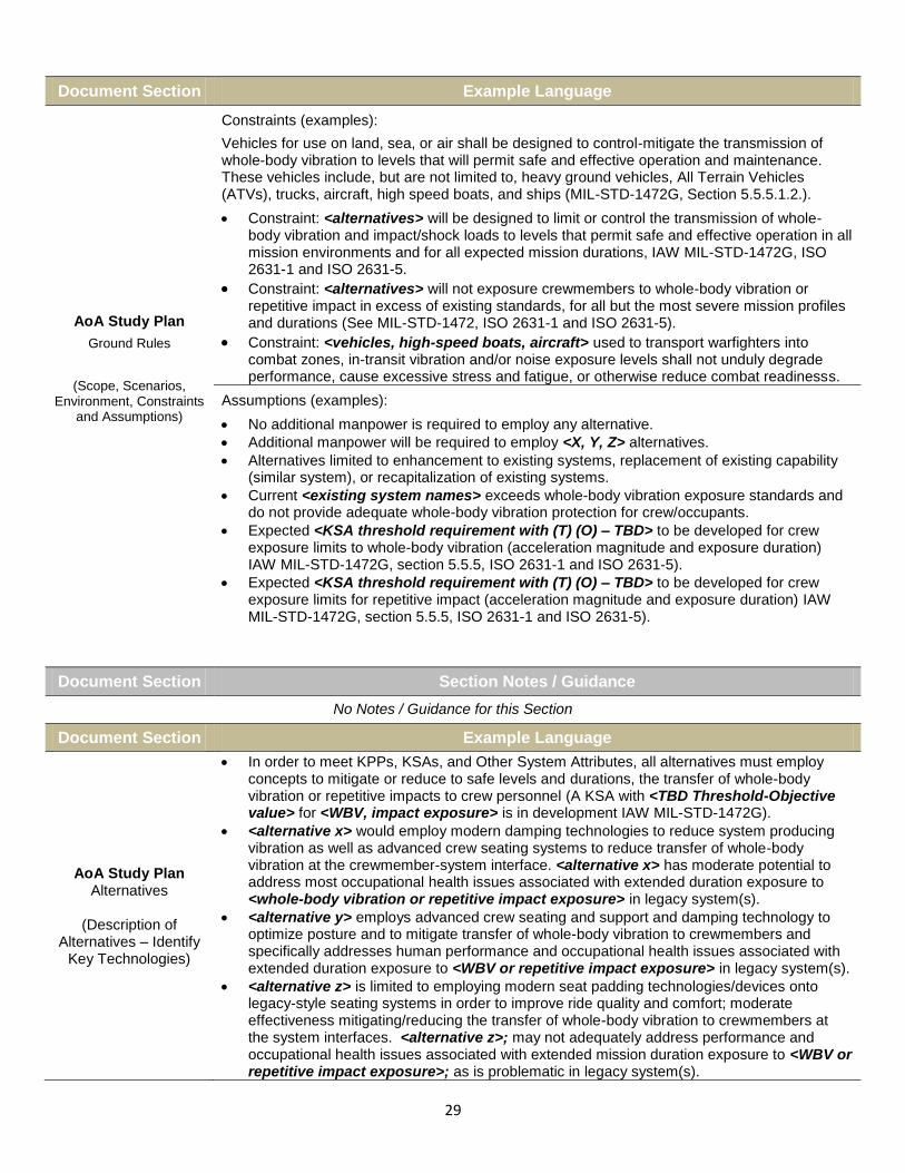
29
Document Section Example Language
AoA Study Plan
Ground Rules
(Scope, Scenarios, Environment, Constraints
and Assumptions)
Constraints (examples):
Vehicles for use on land, sea, or air shall be designed to control-mitigate the transmission of whole-body vibration to levels that will permit safe and effective operation and maintenance. These vehicles include, but are not limited to, heavy ground vehicles, All Terrain Vehicles (ATVs), trucks, aircraft, high speed boats, and ships (MIL-STD-1472G, Section 5.5.5.1.2.).
Constraint: <alternatives> will be designed to limit or control the transmission of whole-body vibration and impact/shock loads to levels that permit safe and effective operation in all mission environments and for all expected mission durations, IAW MIL-STD-1472G, ISO 2631-1 and ISO 2631-5.
Constraint: <alternatives> will not exposure crewmembers to whole-body vibration or repetitive impact in excess of existing standards, for all but the most severe mission profiles and durations (See MIL-STD-1472, ISO 2631-1 and ISO 2631-5).
Constraint: <vehicles, high-speed boats, aircraft> used to transport warfighters into combat zones, in-transit vibration and/or noise exposure levels shall not unduly degrade performance, cause excessive stress and fatigue, or otherwise reduce combat readinesss.
Assumptions (examples):
No additional manpower is required to employ any alternative.
Additional manpower will be required to employ <X, Y, Z> alternatives.
Alternatives limited to enhancement to existing systems, replacement of existing capability (similar system), or recapitalization of existing systems.
Current <existing system names> exceeds whole-body vibration exposure standards and do not provide adequate whole-body vibration protection for crew/occupants.
Expected <KSA threshold requirement with (T) (O) – TBD> to be developed for crew exposure limits to whole-body vibration (acceleration magnitude and exposure duration) IAW MIL-STD-1472G, section 5.5.5, ISO 2631-1 and ISO 2631-5).
Expected <KSA threshold requirement with (T) (O) – TBD> to be developed for crew exposure limits for repetitive impact (acceleration magnitude and exposure duration) IAW MIL-STD-1472G, section 5.5.5, ISO 2631-1 and ISO 2631-5).
Document Section Section Notes / Guidance
No Notes / Guidance for this Section
Document Section Example Language
AoA Study Plan Alternatives
(Description of
Alternatives – Identify Key Technologies)
In order to meet KPPs, KSAs, and Other System Attributes, all alternatives must employ concepts to mitigate or reduce to safe levels and durations, the transfer of whole-body vibration or repetitive impacts to crew personnel (A KSA with <TBD Threshold-Objective value> for <WBV, impact exposure> is in development IAW MIL-STD-1472G).
<alternative x> would employ modern damping technologies to reduce system producing vibration as well as advanced crew seating systems to reduce transfer of whole-body vibration at the crewmember-system interface. <alternative x> has moderate potential to address most occupational health issues associated with extended duration exposure to <whole-body vibration or repetitive impact exposure> in legacy system(s).
<alternative y> employs advanced crew seating and support and damping technology to optimize posture and to mitigate transfer of whole-body vibration to crewmembers and specifically addresses human performance and occupational health issues associated with extended duration exposure to <WBV or repetitive impact exposure> in legacy system(s).
<alternative z> is limited to employing modern seat padding technologies/devices onto legacy-style seating systems in order to improve ride quality and comfort; moderate effectiveness mitigating/reducing the transfer of whole-body vibration to crewmembers at the system interfaces. <alternative z>; may not adequately address performance and occupational health issues associated with extended mission duration exposure to <WBV or repetitive impact exposure>; as is problematic in legacy system(s).
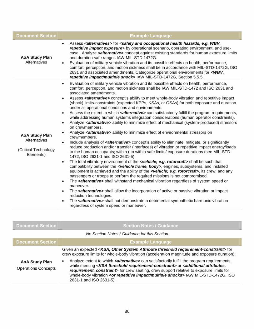
30
Document Section Example Language
AoA Study Plan Alternatives
Assess <alternatives> for <safety and occupational health hazards, e.g. WBV, repetitive impact exposure> by operational scenario, operating environment, and use-case. Analyze <alternative> concept against existing standards for human exposure limits and duration safe ranges IAW MIL-STD 1472G.
Evaluation of military vehicle vibration and its possible effects on health, performance, comfort, perception, and motion sickness shall be in accordance with MIL-STD-1472G, ISO 2631 and associated amendments. Categorize operational environments for <WBV, repetitive impact/multiple shock> IAW MIL-STD-1472G, Section 5.5.5.
AoA Study Plan Alternatives
(Critical Technology
Elements)
Evaluation of military vehicle vibration and its possible effects on health, performance, comfort, perception, and motion sickness shall be IAW MIL-STD-1472 and ISO 2631 and associated amendments.
Assess <alternative> concept’s ability to meet whole-body vibration and repetitive impact (shock) limits-constraints (expected KPPs, KSAs, or OSAs) for both exposure and duration under all operational conditions and environments.
Assess the extent to which <alternative> can satisfactorily fulfill the program requirements, while addressing human systems integration considerations (human operator constraints).
Analyze <alternative> ability to minimize effect of mechanical (system-produced) stressors on crewmembers.
Analyze <alternative> ability to minimize effect of environmental stressors on crewmembers.
Include analysis of <alternative> concept’s ability to eliminate, mitigate, or significantly reduce production and/or transfer (interfaces) of vibration or repetitive impact energy/loads to the human occupants; within ( to within safe limits/ exposure durations (see MIL-STD-1472, ISO 2631-1 and ISO 2631-5).
The total vibratory environment of the <vehicle; e.g. rotorcraft> shall be such that compatibility between the <vehicle frame, body>, engines, subsystems, and installed equipment is achieved and the ability of the <vehicle; e.g. rotorcraft>, its crew, and any passengers or troops to perform the required missions is not compromised.
The <alternative> shall withstand mechanical vibration regardless of system speed or maneuver.
The <alternative> shall allow the incorporation of active or passive vibration or impact reduction technologies.
The <alternative> shall not demonstrate a detrimental sympathetic harmonic vibration regardless of system speed or maneuver.
Document Section Section Notes / Guidance
No Section Notes / Guidance for this Section
Document Section Example Language
AoA Study Plan
Operations Concepts
Given an expected <KSA, Other System Attribute threshold requirement-constraint> for crew exposure limits for whole-body vibration (acceleration magnitude and exposure duration):
Analyze extent to which <alternative> can satisfactorily fulfill the program requirements, while meeting <KSA threshold requirement-constraint> or <additional attributes, requirement, constraint> for crew seating, crew support relative to exposure limits for whole-body vibration <or repetitive impact/multiple shocks> IAW MIL-STD-1472G, ISO 2631-1 and ISO 2631-5).

31
Document Section Example Language
AoA Study Plan
Operations Concepts, Nonviable Alternatives
<alternative x> may meet effectiveness measures for peacetime operations; by limiting mission durations and/or maximizing crew personnel rotation to reduce and maintain individual crew exposure to WBV and/or repetitive impact loads (shocks); to within safe limits IAW MIL-STD-1472G; magnitude/duration limits for vibration and shock.
<alternative x> can meet effectiveness measures for peacetime operations and be within <identified Environment, Safety, and Occupational Health (ESOH) constraints, WBV, repetitive impact limits>, by limiting mission durations and/or maximizing crew personnel rotation to reduce crew exposure to whole-body vibration <or WBV with multiple impacts> to safe limits (as specified in MIL-STD-1472G).
For extended mission durations in operational use-cases of contingency and wartime employment; <alternative x> or <any alternative/concept with legacy system crew station design> is a potentially non-viable alternative as it would not meet WBV and/or repetitive impact exposure <KSA threshold, requirements, constraints> as specified in MIL-STD-1472G, Section 5.5.5. environment categories A, B, C.
Document Section Section Notes / Guidance
AoA Study Plan
Determination of Effectiveness
Measures
Mission Tasks – Do not use solution-specific language. Each mission task should have at least one measure of effectiveness supporting it, and each measure of effectiveness should support at least one mission task.
Measures of Effectiveness – Provide the details that allow the proficiency of each alternative to be quantified.
Measures of Performance – Describe the quantitative measure of a system characteristic chosen to enable calculation of one or more measures of effectiveness.
Document Section Example Language
AoA Study Plan
Determination of Effectiveness
Measures
Vehicles for use on land, sea, or air shall be designed to control the transmission of whole-body vibration to levels that will permit safe and effective operation and maintenance. These vehicles include, but are not limited to, heavy ground vehicles, All Terrain Vehicles (ATVs), trucks, aircraft, high speed boats, and ships, as specified in MIL-STD-1472G.
Regardless of the concepts/alternatives in this analysis, the capability gaps identified in the ICD cannot be mitigated with a materiel solution without acknowledgement of the deficiencies/shortfalls in crew stations/crew systems of <legacy, existing, like-systems>, and providing traceable key system attributes with threshold-objective values included in the overall Measures of Performance (MOPs) and Measures of Effectiveness (MOEs) of the system. <KSA, Additional System Attribute, etc.> related to whole-body vibration and/or repetitive impact (multiple shock) exposure will require development of (T) Threshold and (O) Objective values IAW MIL-STD-1472G and must maintain <x priority> during trade-off analysis among cost, schedule, and performance objectives for each alternative considered.

32
Document Section Section Notes / Guidance
No Section Notes / Guidance for this Section
Document Section Example Language
AoA Study Plan
Cost Analysis
Life Cycle Cost Methodology
(Personnel requirements and
constraints)
Assumption (example): No additional manpower is required to employ any alternative.
Assumption (example): Additional manpower (crews) resources will be required for all alternatives employing <legacy system crew station, interface> concepts.
Constraint (example): For systems which themselves produce stressors, and operate in environments which produce additional stressors to crewmembers or occupants, there exists an increase of the likelihood of performance degradation (e.g. fatigue, safety, situational awareness) as well as occupational health related issues in both the short and long term (e.g. musculoskeletal injuries), increased Life Cycle Cost (LCC) or Total Ownership Cost (TOC) of <alternative>.
<alternative x> system will likely exceed <WBV and/or repetitive impact exposure>; above safe ranges in existing standards for exposure magnitude and/or duration in <x environments> = increase in LCC and TOC due to crew/occupant occupational illnesses, medical treatment needs (near and long term), mission loss, increased personnel requirements (aptitudes, physical fitness, training, shift rotations, crew rest and recovery), change to system use CONOPS/use-case scenario modification, system redesigns, additional personal protective equipment requirements.
Document Section Section Notes / Guidance
No Section Notes / Guidance for this Section
Document Section Example Language
AoA Study Plan
Organization and Management
(Study Team Organization)
Study teams will include a functional panel responsible for Human Systems Integration (HSI) considerations with this AoA, which will include HSI practitioners to aid in analysis of all HSI domain considerations related to system capabilities and constraints.
Study teams will include a functional panel for Human Systems Integration (HSI), considerations with this AoA, which will include HSI practitioners to aid in analysis of all HSI domain considerations related to system capabilities and constraints, especially surrounding expected <Key System Attributes, other/additional system attributes> involving crew systems/cockpit/crew station(s); whole-body vibration and repetitive impact exposure considerations.
All functional panels will support the effectiveness panel. The effectiveness panel will integrate the work of the other panels.
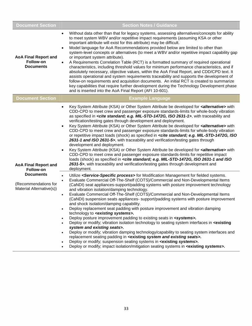
33
Document Section Section Notes / Guidance
AoA Final Report and Follow-on
Documents
Without data other than that for legacy systems, assessing alternatives/concepts for ability to meet system WBV and/or repetitive impact requirements (assuming KSA or other important attribute will exist for this attribute) may be difficult.
Model language for AoA Recommendations provided below are limited to other than system-level concepts or alternatives (to meet a WBV and/or repetitive impact capability gap or important system attribute).
A Requirements Correlation Table (RCT) is a formatted summary of required operational characteristics, including threshold values for minimum performance characteristics, and if absolutely necessary, objective values, within the AoA Final Report, and CDD/CPD text. It assists operational and system requirements traceability and supports the development of follow-on requirements and acquisition documents. An initial RCT is created to summarize key capabilities that require further development during the Technology Development phase and is inserted into the AoA Final Report (AFI 10-601).
Document Section Example Language
AoA Final Report and Follow-on
Documents
(Recommendations for Material Alternative(s))
Key System Attribute (KSA) or Other System Attribute be developed for <alternative> with CDD-CPD to meet crew and passenger exposure standards-limits for whole-body vibration as specified in <cite standard; e.g. MIL-STD-1472G, ISO 2631-1>, with traceability and verification/testing gates through development and deployment.
Key System Attribute (KSA) or Other System Attribute be developed for <alternative> with CDD-CPD to meet crew and passenger exposure standards-limits for whole-body vibration or repetitive impact loads (shock) as specified in <cite standard; e.g. MIL-STD-1472G, ISO 2631-1 and ISO 2631-5>, with traceability and verification/testing gates through development and deployment.
Key System Attribute (KSA) or Other System Attribute be developed for <alternative> with CDD-CPD to meet crew and passenger exposure standards-limits for repetitive impact loads (shock) as specified in <cite standard; e.g. MIL-STD-1472G, ISO 2631-1 and ISO 2631-5>, with traceability and verification/testing gates through development and deployment.
Utilize <Service-Specific process> for Modification Management for fielded systems. Evaluate Commercial Off-The-Shelf (COTS)/Commercial and Non-Developmental Items
(CaNDI) seat appliances-support/padding systems with posture improvement technology and vibration isolation/damping technology.
Evaluate Commercial Off-The-Shelf (COTS)/Commercial and Non-Developmental Items (CaNDI) suspension seats appliances- support/padding systems with posture improvement and shock isolation/damping capability.
Deploy replacement seat padding with posture improvement and vibration damping technology to <existing systems>.
Deploy posture improvement padding to existing seats in <systems>. Deploy or modify; vibration isolation technology to seating system interfaces in <existing
system and existing seats>. Deploy or modify; vibration damping technology/capability to seating system interfaces and
replacement seating padding in <existing system and existing seats>. Deploy or modify; suspension seating systems in <existing systems>. Deploy or modify; impact isolation/mitigation seating systems in <existing systems>.

34
Capability Development Document (CDD) The suggestions, example language provided, and the placement of the language within the document(s) are presented as a reference for acquisition and other professionals. Examples are not necessarily meant to be specific for any particular type of system or acquisition program. Suggestions and examples provided are intended to assist acquisition professionals by providing a starting point for tailoring language unique to
individual development programs. Specific standards can be obtained from an HSI practitioner or from any of the sources identified in the Standards and/or References tab.
The purpose of a CDD is to provide traceability to predecessor documents. It defines authoritative, measurable, and testable parameters across one or more increments of a materiel capability solution, by setting Key Performance Parameters (KPPs), Key System Attributes (KSAs), and additional performance attributes (description, objective, threshold, and analytical references) associated with specific capability solution(s). It also identifies related DOTmLPF-P impacts of each proposed capability solution.
CDD Model Language for Whole-Body Vibration (WBV) and/or Repetitive Impact This section provides model language (examples / statements) to address WBV and/or repetitive impact. Information in the form of Section Notes or Guidance may be provided which is generally applicable to the CDD Section identified. These sections may include Example Tables or other information (with WBV / Impact examples), presented in a CDD-representative format. The examples and formats provided will vary, in order to present the user with broad options and a general starting point for a CDD intended to incorporate WBV and/or repetitive impact as an important attribute(s). The user of this Guide is reminded that the information provided is intended to assist in “crafting” or “tailoring” language most appropriate to their particular program or set of circumstances, not to be a direct “cut-and-paste” solution.
- KEY -
<…> “Insert Applicable Information Here” (i.e. <x>, <X>, <Y>, <Z>, etc.)
<name, value, other>… Same as Above with category or example of information needed
6._._.G-x Placeholder: example “unique identifier” for example language
Table 8: CDD Section
Document Section Section Notes / Guidance
No Notes / Guidance for this section
Document Section Example Language
CDD Section 2
Analysis Summary
Or
“Alternate” CDD Format
Section N/A
<Existing systems> are consistently utilized in environments (extreme terrains) for which the crew systems were not intended to or designed to support (creating ride environments and exposures beyond human physical limitations for safety, health, performance, comfort; IAW MIL-STD-1472G, MIL-STD-882E); adapted mission profiles outside original system employment CONOPS, and Command AOR).
<existing systems, legacy systems> are consistently utilized in extreme environments, for durations in which the crew seat/interface systems (seat ergonomics, seat support, seat padding, seat vibration/impact damping, and combination) were not intended for or originally designed to support (creating ride environments and exposure conditions beyond human physical criteria/limitations for safety, health, performance, comfort; IAW MIL-STD-1472G, MIL-STD-882E); adapted mission profiles outside original system employment CONOPS, and Command AOR).
In <x> environments, <existing systems> produces excessive system (mechanical) vibration with additional environment-produced vibration energy which is transferred to crew stations, crewmembers, and passengers through human-system interface (seats, floor, controls).
Capability Development Document (CDD)
Home
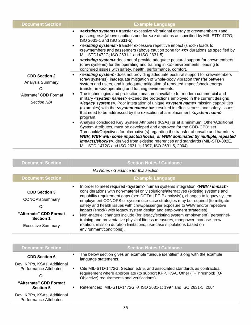
35
Document Section Example Language
CDD Section 2
Analysis Summary
Or
“Alternate” CDD Format
Section N/A
<existing systems> transfer excessive vibrational energy to crewmembers <and passengers> (above caution zone for <x> durations as specified by MIL-STD1472G; ISO 2631-1 and ISO 2631-5).
<existing systems> transfer excessive repetitive impact (shock) loads to crewmembers and passengers (above caution zone for <x> durations as specified by MIL-STD1472G; ISO 2631-1 and ISO 2631-5).
<existing system> does not of provide adequate postural support for crewmembers (crew systems) for the operating and training in <x> environments, leading to continued issues with safety, health, performance, comfort.
<existing system> does not providing adequate postural support for crewmembers (crew systems); inadequate mitigation of whole-body vibration transfer between system and users, and inadequate mitigation of repeated impact/shock energy transfer in <x> operating and training environments.
The technologies and protection measures available for modern commercial and military <system names> exceed the protections employed in the current designs <legacy systems>. Poor integration of unique <system name> mission capabilities (examples) with the <system name> has resulted in effectiveness and safety issues that need to be addressed by the execution of a replacement <system name> program.
Analysis concluded Key System Attributes (KSAs) or at a minimum, Other/Additional System Attributes, must be developed and approved for the CDD-CPD; set Threshold/Objectives for alternative(s) regarding the transfer of unsafe and harmful < WBV, WBV with some impacts/shocks, or WBV dominated by multiple, repeated impacts/shocks>, derived from existing references and standards (MIL-STD-882E, MIL-STD-1472G and ISO 2631-1; 1997, ISO 2631-5, 2004).
Document Section Section Notes / Guidance
No Notes / Guidance for this section
Document Section Example Language
CDD Section 3
CONOPS Summary
Or
“Alternate” CDD Format Section 1
Executive Summary
In order to meet required <system> human systems integration <WBV / impact> considerations with non-materiel only solutions/alternatives (existing systems and capability requirement gaps (see DOTmLPF-P analysis)), changes to legacy system employment CONOPS or system use-case strategies may be required (to mitigate safety and health issues with crew/passenger exposure to WBV and/or repetitive impact (shock) with legacy system design and employment strategies).
Non-materiel changes include (for legacy/existing system employment): personnel-training and preventative physical fitness measures, manpower increase-crew rotation, mission duration limitations, use-case stipulations based on environment/conditions).
Document Section Section Notes / Guidance
CDD Section 6
Dev. KPPs, KSAs, Additional Performance Attributes
Or
“Alternate” CDD Format Section 5
Dev. KPPs, KSAs, Additional Performance Attributes
The below section gives an example “unique identifier” along with the example language statements.
Cite MIL-STD-1472G, Section 5.5.5. and associated standards as contractual
requirement where appropriate (to support KPP, KSA, Other (T-Threshold) (O-Objective) requirements and verifications).
References: MIL-STD-1472G ISO 2631-1; 1997 and ISO 2631-5; 2004

36
Document Section Example Language (Air Vehicles)
CDD Section 6
Dev. KPPs, KSAs, Additional Performance Attributes
Or
“Alternate” CDD Format Section 5
Dev. KPPs, KSAs, Additional Performance Attributes
(Air Vehicles)
6._._.A-x The <system name> shall be designed to minimize system vibration and to mitigate or control the transmission of whole-body vibration to crewmembers and passengers to levels <insert Threshold, insert Objective> that permit safe and effective operation as specified in MIL-STD-1472G section 5.5.5., ISO 2631-1; 1997 (magnitudes and durations of exposure) <Define (T) and (O)>. Rationale: MIL-STD-1472G and associated Standards defines the safe whole-body vibration exposure ranges for personnel spaces and human interfaces. The <existing system> interface systems <seats, foot space, control surfaces, other> are considered insufficient or do not meet standards. 6._._.A-x The <system name> shall be designed to control the transmission of system and environment-induced repeated impact energy (a.k.a. shock) to levels that permit safe and effective operation per MIL-STD-1472G section 5.5.5., ISO 2631-5; 2004 (magnitude and durations of exposure) <Define (T) and (O)>. Rationale: MIL-STD-1472G and associated Standards defines the safe repetitive impact exposure ranges for personnel spaces and human interfaces. The existing <system> interface systems <seats, foot space, control surfaces, other> are considered insufficient or do not meet standards. The <existing system> interface systems <seats, foot space, control surfaces, other> are considered insufficient or do not meet standards.
6._._.A-x The <system> seat(s) or seating systems shall promote good posture in the operational environment and for the duration of the mission by; providing uniform body support over the seat-occupant contact area (not causing “hot spots” to occur), not transmitting vibrations to the occupant of <x> frequencies exceeding <y> amplitudes, and providing back support to reduce lumbar loads and back muscle fatigue. Rationale: MIL-STD-1472G defines personnel spaces based on human factors engineering. The <existing system> seating systems do not meet this requirement.
6._._.A-x <vehicle, system name> seating systems shall be designed to minimize the transmission of vehicle vibration and shock to the occupant. System resonances below 20 Hertz shall be avoided for all MIL-STD-1472G, Section 5.5.5. Category A and B environments. Seating systems shall also minimize vibration in the operating frequency range of the vehicle. Where visual performance is critical, higher frequencies at the seatback and headrest shall be avoided or mitigated.
6._._.A-x The <system name> at <system parameter x, y, z> shall have a Vibration Dose Value (VDV) of no more than <value & units (T) (O)> cumulative, while negotiating <environment, obstacles>, <value> times, at speeds up to and including <value>, for <duration>. (*VDV shall be calculated according to ISO 2631-1 1997). (T) (O) 6._._.A-x The <system name> at <parameter> and <system parameter(s)> shall sustain no more than <value & units> vertical acceleration (T=O), as measured at each crew seat base location while negotiating <environment, obstacles>, at the rated speed of <values>. (Vertical acceleration (peak) shall be calculated IAW ISO 2631-1; 1997). 6._._.A-x For continuous missions lasting <value; e.g. 8.0> hours or less, the seat pan frequency weighted tri-axial Root Mean Square (RMS) accelerations* in any orthogonal direction for any occupied space shall not fall within the “Health Risks are LIKELY” zone for WBV as specified in MIL-STD-1472G, Section 5.5.5. (T) <establish (T) based on mission duration req.; IAW MIL-STD-1472G, Section 5.5.5. and referenced standards> Preferably, the weighted accelerations shall fall within the “Minimal Risk to Health” zone (O) <establish (O) based on mission duration req.; IAW MIL-STD-1472G, Section 5.5.5. and referenced standards>. 6._._.A-x1 For continuous missions lasting more than <value; e.g. 8.0> hours, the seat pan frequency weighted tri-axial RMS accelerations* shall not exceed <value; e.g. 0.315 m/s
2>.
6._._.A-x2 If the weighted accelerations fall within the “Caution Zone” as specified in MIL-STD-1472G, Section 5.5.5., a warning to occupants shall be provided indicating the potential health risk in accordance with MIL-STD-1472G, Section 5.7. (*Tri-axial acceleration data shall be processed in accordance with MIL-STD-1472G, Section 5.5.5.; ISO 2631-1; 1997, using the basic evaluation method and the frequency weightings and multiplying factors for health).

37
Document Section Example Language (Land Vehicles)
CDD Section 6
Dev. KPPs, KSAs, Additional Performance Attributes
Or
“Alternate” CDD Format Section 5
Dev. KPPs, KSAs, Additional Performance Attributes
(Land Vehicles)
6._._.L-x <vehicle, system name> seating systems shall be designed to minimize the transmission of vehicle vibration and shock to the occupant. System resonances below 20 Hertz shall be avoided for all MIL-STD-1472G, Section 5.5.5. Category A and B environments. Seating systems shall also minimize vibration in the operating frequency range of the vehicle. Where visual performance is critical, higher frequencies at the seatback and headrest shall be avoided or mitigated.
6._._.L-x The <system name> shall be designed to control the transmission of whole-body vibration to crewmembers and passengers to levels that permit safe and effective operation per MIL-STD-1472G section 5.5.5., ISO 2631-1; 1997 (magnitude and duration of exposure).
6._._.L-x The <system name> shall be designed to control the transmission of system and environment-induced repeated impact energy (a.k.a. shock) to levels that permit safe and effective operation per MIL-STD-1472G section 5.5.5., ISO 2631-5; 2004 (magnitude and duration of exposure).
6._._.L-x <system name> at <parameter(s)> shall be capable of travelling on 1” <or value> standard Root Mean Square (RMS) course at <value> mph (T) <value> mph (O); 1.5” <or value> standard RMS course at <value> mph (T) <value> mph (O); 2” <or value> standard RMS course at <value> mph (T) <value> mph (O); 2.5” <or value> standard RMS course at <value> mph (T) <value> mph (O); 3” <or value> standard RMS course at <value> mph (T) <value> mph (O) with an average of less <x> Watts of absorbed power at any occupant’s seat (at the interface between the occupant and the seat).
Rationale: <system name> will maneuver as part of the armored <Z> and must be capable of traversing the same terrain as the <XX>. The threshold values represent demonstrated performance of the <YY>. The objective values correspond to the <XX> with <n upgrade>. Achieving this performance will allow the <system name> to maneuver with the rest of the <Z>.
Rationale: <x> Watts absorbed power is the vehicle standard <for system x> that
ensures occupants are combat effective after dismounting the vehicle.
6._._.L-x The <system name> at < parameter> and <system parameter; i.e. gross vehicle weight> shall attain no more than <value & units; i.e. 6W (T) (O)> average vertical absorbed power, as measured at the bottom of all crew seats of the <system name>, while negotiating <value> inch (<value> cm) Root Mean Square (RMS) ride courses at <value> mph (<value> kph), with the tires at cross-country tire pressure.
6._._.L-x The<system name> at <parameter> and <system parameter; i.e. gross vehicle weight> shall sustain no more than <value & units; i.e. 2.5g peak (T) (O)> vertical acceleration, as measured at each crew seat base location while negotiating a non-deformable, half-round <value> inch (<value> cm) obstacle at the rated speed of <value> mph (<value> kph).
6._._.L-x The <system name> at < parameter> and <system parameter; i.e. gross vehicle weight> shall have a Vibration Dose Value (VDV) of no more than <value & units; i.e. m/s^1.75> cumulative, while negotiating a non-deformable, half-round <value> inch (<value> cm) obstacle <value> (<value>) times at speeds up to and including <value> mph (<value> kph). (*VDV shall be calculated according to ISO 2631-1 1997). (T)
6._._.L-x <vehicle, system name> seating systems shall be designed to minimize the transmission of vehicle vibration and shock to the occupant(s) IAW MIL-STD-1472.
6._._.L-x The <system name> will ensure operators experience acceptable noise levels, technically defined as 100% Acoustic Dose (1.0 Total Daily Exposure (TDE) @ mean -2 Standard Deviations (SD) performance for fit) for crew positions in <XX> percent of the system. For systems that do not meet the <XX> percent Acoustic Dose requirement, the <system name> will provide the best available solution within the limits of the design technology.

38
Document Section Example Language (Sea, Surface Vehicles)
CDD Section 6
Dev. KPPs, KSAs, Additional Performance Attributes
Or
“Alternate” CDD Format Section 5
Dev. KPPs, KSAs, Additional Performance Attributes
(Sea, Surface Vehicles)
6._._.S-x The <system name> shall be designed to control the transmission of whole-body vibration to crewmembers and passengers to levels that permit safe and effective operation per MIL-STD-1472G section 5.5.5., ISO 2631-1; 1997 (magnitude and/or duration of exposure).
6._._.S-x The <system name> shall be designed to control the transmission of system and environment-induced repeated impact energy/load (a.k.a. shock) to levels that permit safe and effective operation per MIL-STD-1472G section 5.5.5., ISO 2631-5; 2004. (magnitude and/or duration of exposure - see <___> KSA (T) (O) related to < ___> KPP)
6._._.S-x Maximum segmental and whole-body vibration (and shock) shall be below the criteria provided by (*) or equivalent criteria, for a period of <x> hours (or other suitable interval, based on expected period of exposure and anticipated maintenance operations (for vibrating hand tools).
* Cite reference and/or related criteria, as appropriate to the system under consideration
6._._.S-x The <system name> at <system parameter(s)> shall have an “Daily Equivalent Static Compression Dose Value” (Sed), normalized over and 8.0-hour period (*Sed(8)), of no more than <value & units; e.g. 4.7 MPa (T) and 3.9 MPa (O)> , while negotiating or performing <environment-scenario>, <value> times, at speeds up to and including <value>. (*Sed(8) shall be calculated according to MIL-STD-1472G, Section 5.5.5.; ISO 2631-5; 2004). (T) (O)
6._._.S-x The <system name> shall not exceed an “Daily Equivalent Static Compression Dose Value” (*Sed) of more than <value & units>, while negotiating or performing <missions, environments, scenarios>, <parameters>, for <duration>. (*Sed shall be calculated according to ISO 2631-5; 2004). (T) (O)
6._._.S-x The <system name> at <system parameters > shall sustain no more than <value & units, e.g. * Root Mean Square (RMS) > average vertical absorbed power, as measured at <location> of the <system, subsystem name>, while negotiating <environment-scenario> at <value> speeds, with <other parameters as required>. (*RMS shall be calculated according to ISO 2631-1 1997). (T=O)
6._._.S-x Although the <system> will be designed to function in extreme operational environments where impacts exceed 4.0 G; the <system> and human-interface subsystems (e.g. crew stations, seats) shall be designed to control the transmission of impact energy and shall have a “Daily Equivalent Static Compression Dose Value” (Sed), normalized over and 8.0-hour period (*Sed(8) (or other appropriate value)), of no more than <value & units; e.g. 4.7 MPa (T) and 3.9 MPa (O)> , while negotiating or performing <nominal environment-scenario>, <value> times, at speeds up to and including <value>. (*Sed(8) shall be calculated according to MIL-STD-1472G, Section 5.5.5.; ISO 2631-5; 2004).
6._._.S-x The <system name> at <parameter> and <system parameter> shall sustain no more than <value & units> vertical acceleration, as measured at each crew seat base location while negotiating <environment, obstacles>, at the rated speed of <values> (T). (Vertical acceleration (peak) shall be calculated according to ISO 2631-1 1997). (T=O)
6._._.S-x The <system name> at < system parameters> shall have a Vibration Dose Value (VDV) of no more than <value & units> cumulative, while negotiating <environment, obstacles>, <x> times, <duration> at speeds up to and including <value>. (*VDV shall be calculated according to ISO 2631-1 1997). (T=O)
6._._.G-x The <system> shall minimize noise and vibration hazards to crews and support personnel working near the <system> or its supporting infrastructure through engineering controls <objective> or a combination of engineering, administrative procedures and protective equipment <threshold> to ensure personnel noise exposures are below <value> and maximum segmental and whole-body vibration are below the criteria as specified in <cite reference; e.g. MIL-STD-1472G, Section 5.5.5. and ISO 2631 and all OPNAVINST 5100.24B>

39
Document Section Example Language (General)
CDD Section 6
Dev. KPPs, KSAs, Additional Performance Attributes
Or
“Alternate” CDD Format Section 5
Dev. KPPs, KSAs, Additional Performance Attributes
(General; Vibration/Impact, HSI)
6._._.G-x Potential ESOH <specifically WBV and impact> risks will be identified and managed in accordance with MIL-STD-882E. Designs shall consider the following order of precedence of MIL-STD-882E for risk mitigation of identified hazards:
Eliminate hazards through design selection
Incorporate safety devices
Provide warning devices
Develop procedures and training
6._._.G-x Human factors engineering principles and design standards shall be applied to the design of the system. Designs shall be consistent with human factors engineering references <MIL-STD-46855A, MIL-STD-882E, MIL-STD-1472G; insert related criteria, as appropriate to the system under consideration>.
6._._.G-x Human factors engineering shall be employed during systems engineering over the life of the program to provide for effective human-machine interfaces, enhance personnel performance, ensure that systems and equipment are designed for the physical dimensions, capabilities and limitations of the user population(s) and to meet HSI maintenance, safety and communications requirements (T=O).
6._._.G-x System designs shall minimize or eliminate system characteristics that require extensive training or workload-intensive tasks; result in mission-critical errors; or produce safety or health hazards. Designs will be consistent with human factors engineering criteria per references <MIL-STD-46855A, MIL-STD-882E, MIL-STD-1472G; insert related criteria as appropriate to the system under consideration> (T=O).
6._._.G-x Equipment design and use procedures should minimize the potential for ergonomic injuries. Ergonomic injuries include damage to joints, muscles, and bones due to design features that require repetitive motion, stresses to neck and back muscles, excessive weight lifting and similar workplace activities where human musculoskeletal capabilities and limitations have not been addressed in the design (O).
6._._.G-x The <system name> will address applicable HSI domains (Manpower, Personnel, Training, HFE, ESOH, Personnel Survivability, and Habitability) to optimize total system performance, minimize total operational cost, and ensure the system is built to accommodate the characteristics of the user population in relation to whole-body vibration reduction/prevention that will operate, maintain, and support the system.
6._._.G-x For the <system>, safety considerations shall be provided for in the program baseline to support sustainable operation and maintenance. The program shall maintain a <system> safety process to identify and prevent ESOH hazards where possible, and shall manage ESOH hazards where they cannot be avoided.
6._._.G-x The system shall be designed to eliminate or mitigate safety, health or physical risks pertaining to whole-body vibration IAW MIL-STD-1472. Rationale: Where hazards/risks exist, health and safety equipment and/or procedures must be identified. Health and Safety procedures and engineering design considerations must conform to all pertinent standards. Crew task load, fatigue factors, broad range of operation environments, and data assimilation must be considered.
6._._.G-x The crew and passengers/troops shall not be exposed to vibrations which reduce their effectiveness or increase their workload while performing their required missions. Rationale: MIL-STD-1472G, section 5.5.5, ISO 2631-1
6._._.G-x The crew and passengers/troops shall not be exposed to individual or repeated jarring impacts which reduce their effectiveness or increase their workload while performing their required missions. Rationale: MIL-STD-1472G, section 5.5.5., ISO 2631-5
6._._.G-x The total vibratory environment of the rotorcraft shall be such that compatibility between the airframe, engines, subsystems, and installed equipment is achieved and the ability of the rotorcraft, its crew, and any passengers or troops to perform the required missions is not compromised. Rationale: MIL-STD-1472G, Section 5.5.5., ISO 2631-1

40
Document Section Example Language (General)
CDD Section 6
Dev. KPPs, KSAs, Additional Performance Attributes
Or
“Alternate” CDD Format Section 5
Dev. KPPs, KSAs, Additional Performance Attributes
(General; Vibration/Impact, HSI)
6._._.G-x The total vibratory environment of the <vehicle type> shall be such that compatibility between the <vehicle frame>, engines, subsystems, and installed equipment is achieved and the ability of the <vehicle type>, its crew, and any passengers or troops to perform the required missions is not compromised. Rationale: MIL-STD-1472G, Section 5.5.5., ISO 2631-1
6._._.G-x All human engineering aspects shall be in compliance with current Human Factors Engineering (HFE) practices and coordinated by a Human Factors Engineer.
6._._.G-x The program will assess manpower requirements for the identified system. The system shall be adequately staffed to ensure the safe and efficient mission completion.
6._._.G-x The program will work with the training community to identify the training requirements for assessed manpower needs and established user population. Training shall support safe and efficient mission accomplishment.
Document Section Section Notes / Guidance
CDD Section 6
Dev. KPPs, KSAs, Additional Performance Attributes
Or
“Alternate” CDD Format Section 5
Dev. KPPs, KSAs, Additional Performance Attributes
(Summary Tables)
The CDD calls for tables summarizing specified KPPs, KSAs, and additional performance attributes in threshold/objective format.
Example tables with representative/example vibration and repetitive impact language are provided below (Tables 9, 10 and 11). The tables are roughly formatted according to CDD development guidance. See Tables 9, 10, and 11 at the end of the CDD section.
J
Document Section Section Notes / Guidance
CDD Section 15
Other System Attributes
Or
“Alternate” CDD Format Section 6
Other System Attributes
The purpose of this CDD section is to identify any other attributes not previously identified, especially those that tend to be design, cost, or risk drivers. This section should include Human Systems Integration (HSI) considerations that have a major impact on system effectiveness and suitability.
Other system attributes may include, but are not limited to, the following: o Human Systems Integration (HSI) considerations that have a major impact on
system effectiveness and suitability. o Natural environmental factors (climatic design type, terrain, meteorological
and oceanographic factors, impacts and effects). o Expected level of capability provided in various mission environments, if
degraded relative to KPPs, KSAs, and additional performance attributes articulated in Section (6/5) of the CDD. Include applicable safety parameters, such as those related to system, nuclear, explosive, and flight safety.
Considering it may be unlikely that system WBV and/or repetitive impact attributes/constraints make the KPP or KSA level of “priority” (prioritization, trade-off analyses, etc.), the model language provided in previous CDD sections (i.e. such as those listed as higher level system parameters or attributes (KPPs, KSAs, Additional Performance Attributes, etc.)), may be used, in addition to the below examples, to tailor/derive appropriate Other System Attributes

41
Document Section Example Language
CDD Section 15
Other System Attributes
Or
“Alternate” CDD Format Section 6
Other System Attributes
Will comply with the DoD policy on system production and transmission to occupants of whole-body vibration and/or repetitive impact (shock) in accordance with MIL-STD-1472G “Design Criteria Standard; Human Engineering”, Section 5.5.5. “Vibration and Shock”.
Will control or mitigate the transmission of whole-body vibration to crewmembers and passengers to levels that permit safe and effective operation per MIL-STD-1472G section 5.5.5., ISO 2631-1; 1997 (Define (T) and (O).
Rationale: MIL-STD-1472 defines the safe whole-body vibration exposure ranges for personnel spaces and human interfaces. The <existing system> interface systems <seats, foot space, control surfaces, other> are considered insufficient or do not meet these standards.
Will control or mitigate the transmission of system and environment-induced repeated impact energy to levels that permit safe and effective operation per MIL-STD-1472G section 5.5.5., ISO 2631-5; 2004 (Define (T) and (O).
Rationale: MIL-STD-1472 defines the safe repetitive impact exposure ranges for personnel spaces and human interfaces. The existing <system> interface systems <seats, foot space, control surfaces, other> are considered insufficient or do not meet standards. The <existing system> interface systems <seats, foot space, control surfaces, other> are considered insufficient or do not meet these standards.
(Capture natural environmental factors (climatic design type, terrain, meteorological and oceanographic factors, impacts and effects)):
The <system> will be capable of operating in conditions or environments in which exposure of operators and occupants to whole-body vibration may reach health hazard zones identified by existing standards as “Health Risks are LIKELY” as specified in MIL-STD-1472, under extreme conditions or circumstances.
Rationale: Although the <new systems> shall to be designed to control or mitigate the transfer of whole-body vibration to crewmembers and occupants during the majority of use environments (see WBV exposure <KSA #______ or Additional System Attribute #______ (T) and (O))>, the <system> shall not artificially or automatically limit the performance envelope of the overall system (potential Key Performance Parameters or excess capability) in high-threat environments, extreme operational scenarios, or emergency conditions or use-cases. In extreme use-cases, occupational health (ESOH) risks to occupants become inherent in the system and must be subservient to overall system safety parameters/survivability.
Rationale: Identified requirement reflects mission profile and employment scenario and are required for safety of crew and mission accomplishment.
Document Section Section Notes / Guidance
CDD Section 14
Or
“Alternate” CDD Format Section 11
DOTmLPF-P Considerations
Discuss any DOTmLPF-P changes associated with fielding the system, to include those approaches that would impact CONOPS or plans within an Area of Responsibility (AOR). Describe the implications for all recommended changes (examples relative to vehicular vibration and impact reduction below).
For DOTmLPF-P changes already addressed in separate Joint DCRs, cite the DCR which applies and provide status.
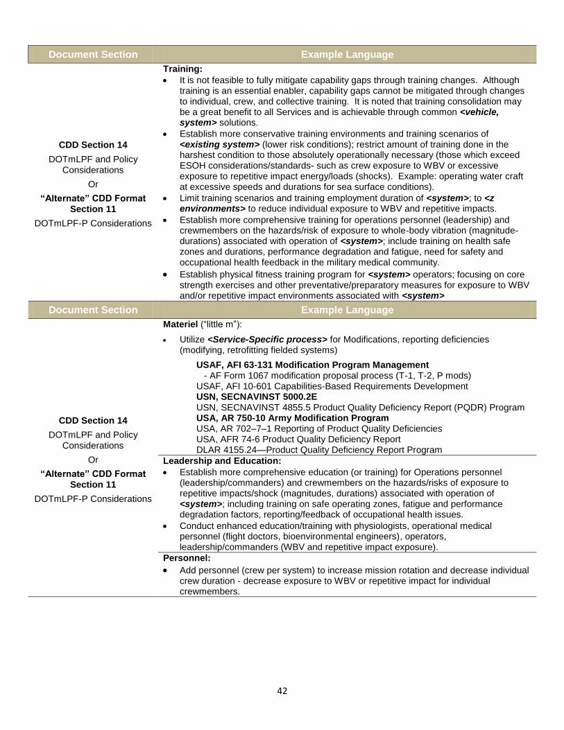
42
Document Section Example Language
CDD Section 14
DOTmLPF and Policy Considerations
Or
“Alternate” CDD Format Section 11
DOTmLPF-P Considerations
Training:
It is not feasible to fully mitigate capability gaps through training changes. Although training is an essential enabler, capability gaps cannot be mitigated through changes to individual, crew, and collective training. It is noted that training consolidation may be a great benefit to all Services and is achievable through common <vehicle, system> solutions.
Establish more conservative training environments and training scenarios of <existing system> (lower risk conditions); restrict amount of training done in the harshest condition to those absolutely operationally necessary (those which exceed ESOH considerations/standards- such as crew exposure to WBV or excessive exposure to repetitive impact energy/loads (shocks). Example: operating water craft at excessive speeds and durations for sea surface conditions).
Limit training scenarios and training employment duration of <system>; to <z environments> to reduce individual exposure to WBV and repetitive impacts.
Establish more comprehensive training for operations personnel (leadership) and crewmembers on the hazards/risk of exposure to whole-body vibration (magnitude-durations) associated with operation of <system>; include training on health safe zones and durations, performance degradation and fatigue, need for safety and occupational health feedback in the military medical community.
Establish physical fitness training program for <system> operators; focusing on core strength exercises and other preventative/preparatory measures for exposure to WBV and/or repetitive impact environments associated with <system>
Document Section Example Language
CDD Section 14
DOTmLPF and Policy Considerations
Or
“Alternate” CDD Format Section 11
DOTmLPF-P Considerations
Materiel (“little m”):
Utilize <Service-Specific process> for Modifications, reporting deficiencies (modifying, retrofitting fielded systems)
USAF, AFI 63-131 Modification Program Management - AF Form 1067 modification proposal process (T-1, T-2, P mods) USAF, AFI 10-601 Capabilities-Based Requirements Development USN, SECNAVINST 5000.2E USN, SECNAVINST 4855.5 Product Quality Deficiency Report (PQDR) Program USA, AR 750-10 Army Modification Program USA, AR 702–7–1 Reporting of Product Quality Deficiencies USA, AFR 74-6 Product Quality Deficiency Report DLAR 4155.24—Product Quality Deficiency Report Program
Leadership and Education:
Establish more comprehensive education (or training) for Operations personnel (leadership/commanders) and crewmembers on the hazards/risks of exposure to repetitive impacts/shock (magnitudes, durations) associated with operation of <system>; including training on safe operating zones, fatigue and performance degradation factors, reporting/feedback of occupational health issues.
Conduct enhanced education/training with physiologists, operational medical personnel (flight doctors, bioenvironmental engineers), operators, leadership/commanders (WBV and repetitive impact exposure).
Personnel:
Add personnel (crew per system) to increase mission rotation and decrease individual crew duration - decrease exposure to WBV or repetitive impact for individual crewmembers.

43
Document Section Example Language
CDD Section 14
DOTmLPF and Policy Considerations
Or
“Alternate” CDD Format Section 11
DOTmLPF-P Considerations
Policy:
Enforce adherence to existing standards for occupant exposure to whole-body vibration and repetitive impact (shock) in operations employment and training employment of <system(s)> (safety, occupational health) Further research efforts to acquire actual exposure measurements (mission data; WBV, repetitive impact) in operational environments for <system(s), air, land, sea> to correlate with standards, existing technologies, and new engineering approaches.
Further epidemiological studies through the military medical community and laboratories (study causal relationships, dose-response, occupational health issues, safety and total system performance) for military vehicles (air, land, sea) related to whole-body vibration and repetitive impact loads (shocks) exposure; correlate results with Total Ownership Cost (TOC) of <existing system(s)> and expected TOC for future, like-systems.
Continue refinement of existing standards related to whole-body vibration and repetitive impact (shock) exposure based on research, actual system measurement, and analysis.
Table 9: Example KPP Table (CDD)
Tier 1 & Tier 2 Joint Capability Areas (JCAs)
Key Performance Parameter Development Threshold Development Objective
Force Support (1.0)
- Force Preparation (1.2)
- Health Readiness (1.4)
Force Protection
The <system> shall provide occupant(s) protection against harmful exposure to system produced and/or environment produced whole-body vibration or repetitive impact (shock) <Threshold value>
(T=O) See Annex <x> See MIL-STD-1472G, Section 5.5.5.
Table 10: Example KSA Table (CDD)
Tier 1 & Tier 2 Joint Capability Areas (JCAs)
Key System Attribute Development Threshold Development Objective
Force Application (3.0)
- Maneuver (3.1
Crew Safety & Health Crew Performance Range Time on Station
The <system> shall mitigate or provide occupant(s) required protection against harmful exposure levels of system produced and/or environment produced whole-body vibration or repetitive impact (a.k.a. shock) <Threshold value>
(T=O), or <Objective values> Set Objective as appropriate
Force Support (1.0) - Force Preparation (1.2) - Health Readiness (1.4)
Whole-Body Vibration Human Impact Exposure Crew Safety & Health Occupant Safety Crew Performance Ride Quality
The <system> shall be capable of <mission performance, duration, other parameters, etc.> with WBV or shock exposure values <blank> less than <blank>, and for <blank> duration <Threshold value>
(T=O), or <Objective values> Set Objective as appropriate
Force Support (1.0)
- Force Preparation (1.2) - Health Readiness (1.4)
Total Ownership Cost (Occupational Health Contribution)
The <system> shall have a total ownership cost less than or equal to… <Threshold value>
The <system> shall have a total ownership cost less than or equal to…<Objective values>
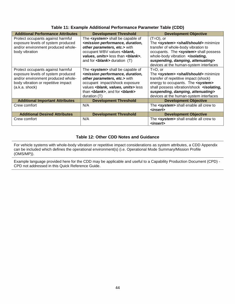
44
Table 11: Example Additional Performance Parameter Table (CDD)
Additional Performance Attributes Development Threshold Development Objective
Protect occupants against harmful exposure levels of system produced and/or environment produced whole-body vibration
The <system> shall be capable of <mission performance, duration, other parameters, etc.> with occupant WBV values <blank, values, units> less than <blank>, and for <blank> duration (T)
(T=O), or The <system> <shall/should> minimize transfer of whole-body vibration to occupants. The <system> shall possess whole-body vibration <isolating, suspending, damping, attenuating> devices at the human-system interfaces
Protect occupants against harmful exposure levels of system produced and/or environment produced whole-body vibration or repetitive impact (a.k.a. shock)
The <system> shall be capable of <mission performance, duration, other parameters, etc.> with occupant impact/shock exposure values <blank, values, units> less than <blank>, and for <blank> duration (T)
T=O, or The <system> <shall/should> minimize transfer of repetitive impact (shock) energy to occupants. The <system> shall possess vibration/shock <isolating, suspending, damping, attenuating> devices at the human-system interfaces
Additional Important Attributes Development Threshold Development Objective
Crew comfort N/A The <system> shall enable all crew to <insert>
Additional Desired Attributes Development Threshold Development Objective
Crew comfort N/A The <system> shall enable all crew to <insert>
Table 12: Other CDD Notes and Guidance
For vehicle systems with whole-body vibration or repetitive impact considerations as system attributes, a CDD Appendix can be included which defines the operational environment(s) (i.e. Operational Mode Summary/Mission Profile (OMS/MP)).
Example language provided here for the CDD may be applicable and useful to a Capability Production Document (CPD) - CPD not addressed in this Quick Reference Guide.
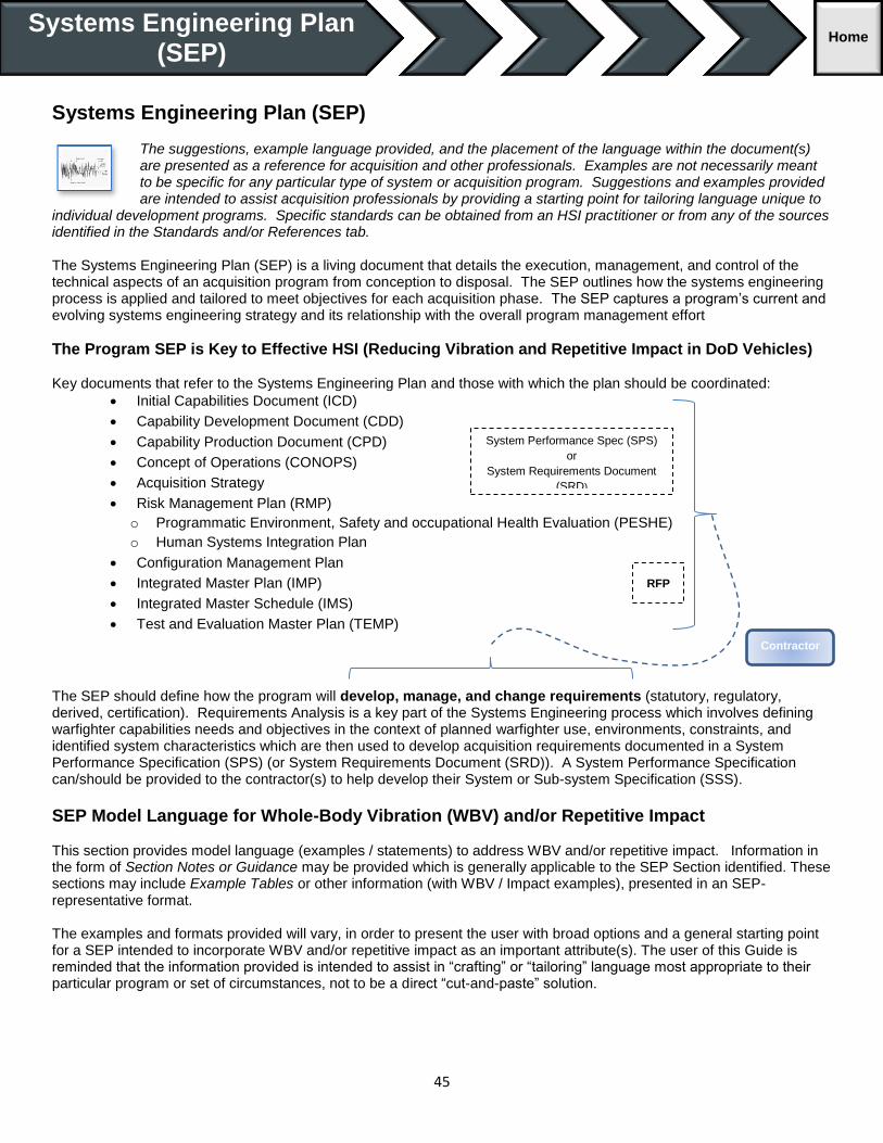
45
Systems Engineering Plan (SEP) The suggestions, example language provided, and the placement of the language within the document(s) are presented as a reference for acquisition and other professionals. Examples are not necessarily meant to be specific for any particular type of system or acquisition program. Suggestions and examples provided are intended to assist acquisition professionals by providing a starting point for tailoring language unique to
individual development programs. Specific standards can be obtained from an HSI practitioner or from any of the sources identified in the Standards and/or References tab. The Systems Engineering Plan (SEP) is a living document that details the execution, management, and control of the technical aspects of an acquisition program from conception to disposal. The SEP outlines how the systems engineering process is applied and tailored to meet objectives for each acquisition phase. The SEP captures a program’s current and evolving systems engineering strategy and its relationship with the overall program management effort
The Program SEP is Key to Effective HSI (Reducing Vibration and Repetitive Impact in DoD Vehicles)
Key documents that refer to the Systems Engineering Plan and those with which the plan should be coordinated:
Initial Capabilities Document (ICD)
Capability Development Document (CDD)
Capability Production Document (CPD)
Concept of Operations (CONOPS)
Acquisition Strategy
Risk Management Plan (RMP)
o Programmatic Environment, Safety and occupational Health Evaluation (PESHE)
o Human Systems Integration Plan
Configuration Management Plan
Integrated Master Plan (IMP)
Integrated Master Schedule (IMS)
Test and Evaluation Master Plan (TEMP)
The SEP should define how the program will develop, manage, and change requirements (statutory, regulatory, derived, certification). Requirements Analysis is a key part of the Systems Engineering process which involves defining warfighter capabilities needs and objectives in the context of planned warfighter use, environments, constraints, and identified system characteristics which are then used to develop acquisition requirements documented in a System Performance Specification (SPS) (or System Requirements Document (SRD)). A System Performance Specification can/should be provided to the contractor(s) to help develop their System or Sub-system Specification (SSS).
SEP Model Language for Whole-Body Vibration (WBV) and/or Repetitive Impact This section provides model language (examples / statements) to address WBV and/or repetitive impact. Information in the form of Section Notes or Guidance may be provided which is generally applicable to the SEP Section identified. These sections may include Example Tables or other information (with WBV / Impact examples), presented in an SEP-representative format. The examples and formats provided will vary, in order to present the user with broad options and a general starting point for a SEP intended to incorporate WBV and/or repetitive impact as an important attribute(s). The user of this Guide is reminded that the information provided is intended to assist in “crafting” or “tailoring” language most appropriate to their particular program or set of circumstances, not to be a direct “cut-and-paste” solution.
Systems Engineering Plan (SEP)
Home
System Performance Spec (SPS)
or
System Requirements Document
(SRD)
RFP
Contractor

46
- KEY -
<…> “Insert Applicable Information Here” (i.e. <x>, <X>, <Y>, <Z>, etc.)
<name, value, other>… Same as Above with category or example of information needed
6._._.G-x Placeholder: example “unique identifier” for example language
“SPS” and “SRD” A “System Performance Specification (SPS)” and a “System Requirements Document (SRD)” are nominally the same document/artifact, and within this QRG, may be used interchangeably.
References to “HSI” “ESOH” WBV and/or repetitive impact exposure (mitigation/reduction) is an “implied” consideration
Table 13: SEP Section
Document SEP Notes / Guidance
SEP
SEP should be a “living” “go-to” technical planning document and the blueprint for the conduct, management, and control of the technical aspects of the government’s program from concept to disposal. SE planning should be kept current throughout the acquisition lifecycle.
SEP should be updated after contractor award to reflect selected contractors’ technical strategy reflected in contractor SEP/SEMP.
Regardless of the Acquisition Category of their programs, PMs must integrate system safety risk management into their overall systems engineering and risk management process. PMs must ensure to integrate the ESOH (which includes WBV and repetitive impact considerations) risk management strategy into the systems engineering process is incorporated in the SEP.
Document Section Section Notes / Guidance
SEP Section 2
Technical Certifications
Any Certifications required related to Vibration and Impact should be addressed in this section.
Table 14 below provides an example Technical Certifications table with representative language/examples which may or may not apply to WBV and/or repetitive impact considerations for your program. The table is roughly formatted according to SEP development guidance. See Table 14 at the end of the SEP section.
Document Section Section Notes / Guidance
SEP Section 3
Engineering and Integration Risk Management
Risk Management is an important aspect of the SEP for tracking HSI considerations/concerns such as WBV and/or repetitive impact exposure.
Identify the way (risk tools) in which the Program Management Office (PMO), and the developing contractor(s), will perform risk management program risks; if possible, the same tool(s) should be used.
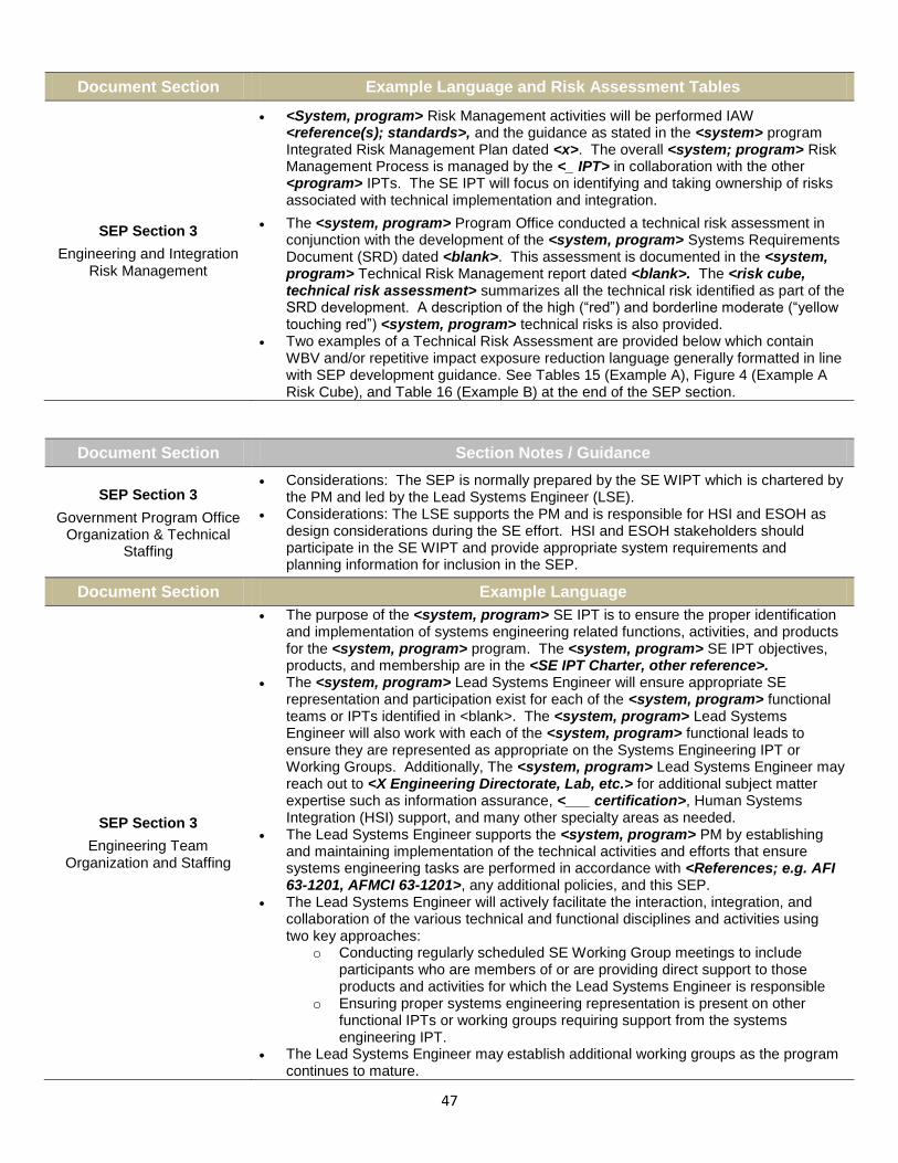
47
Document Section Example Language and Risk Assessment Tables
SEP Section 3
Engineering and Integration Risk Management
<System, program> Risk Management activities will be performed IAW <reference(s); standards>, and the guidance as stated in the <system> program Integrated Risk Management Plan dated <x>. The overall <system; program> Risk Management Process is managed by the <_ IPT> in collaboration with the other <program> IPTs. The SE IPT will focus on identifying and taking ownership of risks associated with technical implementation and integration.
The <system, program> Program Office conducted a technical risk assessment in conjunction with the development of the <system, program> Systems Requirements Document (SRD) dated <blank>. This assessment is documented in the <system, program> Technical Risk Management report dated <blank>. The <risk cube, technical risk assessment> summarizes all the technical risk identified as part of the SRD development. A description of the high (“red”) and borderline moderate (“yellow touching red”) <system, program> technical risks is also provided.
Two examples of a Technical Risk Assessment are provided below which contain WBV and/or repetitive impact exposure reduction language generally formatted in line with SEP development guidance. See Tables 15 (Example A), Figure 4 (Example A Risk Cube), and Table 16 (Example B) at the end of the SEP section.
Document Section Section Notes / Guidance
SEP Section 3
Government Program Office Organization & Technical
Staffing
Considerations: The SEP is normally prepared by the SE WIPT which is chartered by the PM and led by the Lead Systems Engineer (LSE).
Considerations: The LSE supports the PM and is responsible for HSI and ESOH as design considerations during the SE effort. HSI and ESOH stakeholders should participate in the SE WIPT and provide appropriate system requirements and planning information for inclusion in the SEP.
Document Section Example Language
SEP Section 3
Engineering Team Organization and Staffing
The purpose of the <system, program> SE IPT is to ensure the proper identification and implementation of systems engineering related functions, activities, and products for the <system, program> program. The <system, program> SE IPT objectives, products, and membership are in the <SE IPT Charter, other reference>.
The <system, program> Lead Systems Engineer will ensure appropriate SE representation and participation exist for each of the <system, program> functional teams or IPTs identified in <blank>. The <system, program> Lead Systems Engineer will also work with each of the <system, program> functional leads to ensure they are represented as appropriate on the Systems Engineering IPT or Working Groups. Additionally, The <system, program> Lead Systems Engineer may reach out to <X Engineering Directorate, Lab, etc.> for additional subject matter expertise such as information assurance, <___ certification>, Human Systems Integration (HSI) support, and many other specialty areas as needed.
The Lead Systems Engineer supports the <system, program> PM by establishing and maintaining implementation of the technical activities and efforts that ensure systems engineering tasks are performed in accordance with <References; e.g. AFI 63-1201, AFMCI 63-1201>, any additional policies, and this SEP.
The Lead Systems Engineer will actively facilitate the interaction, integration, and collaboration of the various technical and functional disciplines and activities using two key approaches:
o Conducting regularly scheduled SE Working Group meetings to include participants who are members of or are providing direct support to those products and activities for which the Lead Systems Engineer is responsible
o Ensuring proper systems engineering representation is present on other functional IPTs or working groups requiring support from the systems engineering IPT.
The Lead Systems Engineer may establish additional working groups as the program continues to mature.

48
Document Section Example Language
SEP Section 3
Engineering Team Organization and Staffing
Objectives of the <system> SE IPT include (not all inclusive; WBV relevant examples given):
Establish the OSS&E Baseline Document (OBD) planning and implementation Identify and assess program technical risks Implement Operational Safety, Suitability, and Effectiveness. Implement Human Systems Integration (HSI) program Identify all sources of requirements for the SPS <or SRD> Define Technical Performance Measures (based on technical risks) Identify needed or additional system analyses and/or trade studies (based on
risks) The <system> SE IPT will be responsible for the specific SE related products (not all inclusive; WBV relevant examples given):
HSI Plan Operational Safety, Suitability, and Effectiveness Plan Programmatic Environment, Safety, and Occupational Health Evaluation Requirements Management and Traceability Plan System Performance Specification (SPS) <or System Requirements Document
(SRD)> System Safety Plan Systems Engineering Plan Technical Performance Measures Report
Document Section Section Notes / Guidance
SEP Section 3
Engineering Team Organization and Staffing
(Summary Table)
The SEP may include tables summarizing roles and responsibilities of the technical members of the Program IPT(s). HSI representation (WBV and/or repetitive impact Subject Matter Experts (SMEs) may be important to your program.
An example IPT summary table is provided below (representative of a Program with priority given to HSI considerations (e.g. system WBV and/or repetitive impact reduction)). See Table 17 at the end of the SEP section.
Document Section Section Notes / Guidance
SEP Section 3 Technical Performance Measures and Metrics
(Example TPM Table)
The <system> Program Office will develop a TPM program associated with identified
technical risks and reliability measures.
If possible, Section <3.6.> Technical Performance Measures (TPMs) should be
coupled with Section <3.3.> Risks.
An example TPM summary table with representative WBV and/or repetitive impact
language are is provided below (Table 18).
The notional TPMs in the below example correlate with notional Risks from SEP
Section 3 Risks (Example A). See table 18 at the end of the SEP section.
Document Section Section Notes / Guidance
SEP Section 4
Results of Previous Phase SE Activities, Planed SE Activities for Next Phase
(Examples – Considerations)
This section of the SEP highlights multiple “example” areas of the overall SE approach in which efforts to control/mitigate/reduce WBV and/or repetitive impact exposure in a system are relevant and applicable.
The references provided are based on a notional Program SEP and Program phase (not all-inclusive).

49
Document Section Example Language
SEP Section 4
(Results of Previous Phase SE Activities)
Examples for Consideration
Development Planning activities have been taking place since <date>. The emphasis
of these activities has been to <X; e.g. “prepare an acquisition strategy approach
for a Pre-MS B RFP release”>. SE activities include the development of the
following (examples):
System Requirements Document (SRD) development to include requirements management
Configuration Management Planning Human System Integration Planning ESOH Planning Technical Risk Assessment Survivability and Vulnerability Planning
SEP Section 4
(Planned SE Activities for the Next Phase)
Examples for Consideration
The main challenges facing the <system, program> effort will be: Integrating <x> equipment into the <system> Determining the physical design and layout of passenger [and crew]
accommodations Ensuring adequate vibration or impact control or mitigation techniques to meet all
mission requirements The <program > SE community will work with the PM, Contracts, and other <system, program> functional leads to take the results from the previous SE activities to build the usual set of RFP content to include:
Statement of Work (SOW) tasks Contract Data Requirements List (CDRL) Contract Line Item Numbers (CLIN) Section L (Instructions to Offerors) and Section M (Source Selection Evaluation
Criteria) Once a contract has been award for the <program, system> integration effort, the SEP will need to be updated with the main purpose of integrating the Program Office and contractor SE processes and practices (Notionally, this list of activities might include):
Systems Engineering Management Formalize SE Working Group or SE IPT Formalize Requirements Working Group Formalize Human Systems Integration Working Group Formalize System Safety Working Group Integrate or consolidate Systems Engineering Planning Integrate or consolidate the Program Office WBS Integrate and consolidate the SE portion of the IMS Formalize initial set of entry and exit criteria for all planned design reviews/audits Formalize a detailed set of entry exit criteria a minimum of six months prior to a
planned design review or audit date Refine and update technical risks and mitigation plans within __ days of contract
award Refine and update technical risks and mitigation plans within __ days of each
design review Refine and update TPMs simultaneously with technical risk updates Formalize configuration control/change management for system level
requirements Requirements and Architectures Iterate and refine the requirements in the SRD for baseline approval at the SRR Further derive and decompose requirements for subsequent design reviews Assess technical integration challenges and management solutions Identify and conduct any trade studies needed before implementing final
integration solutions Link applicable trade studies to technical risks, TPMs, and integration challenges Establish traceability between the government SRD and the contractor functional
baseline Active participation in the <WBV, impact reduction Working Group>

50
Document Section Section Notes / Guidance
SEP Section 4
(Requirements Management and Change Process)
Describe the guidelines used by the <system, program> program office for establishing the requirements database, requirements attributes, requirements measurements, and traceability in order to develop and manage system-level requirements. The approach (or plan) should define roles and responsibilities, the process for managing requirements, and the tools and resources necessary to accomplish the specified tasks.
SEP Section 4
(4.6. Design Considerations)
(Table 4.6-1)
The SEP Outline requires that HSI and ESOH be addressed as a mandatory design consideration in Table 4.6-1.
The SEP Table 4.6-1 requires:
Identification of the organizational structure and responsibilities for the HSI and ESOH efforts; identification of required approvals, endorsements, releases, and User Representatives for concurrence on High and Serious ESOH risk acceptances
Identification of required documentation attached to the SEP Table (the Programmatic ESOH Evaluation and National Environmental Policy Act (NEPA)/Executive Order (EO) 12114 Compliance Schedule at MS B and C, and a NEPA Compliance Schedule covering TMRR applicable activities for MS A)
Identification of HSI and ESOH contractual requirements and Contract Deliverables Requirements List (CDRL) items; a summary how HSI will be integrated within the SE processes, specifically addressing the human operator and maintainer requirement allocation approach that accounts for total system performance
A description of how the design minimizes ESOH risks by summarizing how the program has integrated ESOH considerations into SE processes including the method for tracking hazards and ESOH risks and mitigation plans throughout the life cycle of system
Defense Acquisition Guidebook (DAG) Section 4.4 and Tables 4.6-1 and 4.6-2 in the Systems Engineering Plan (SEP) Outline contain non-exhaustive lists of design considerations. Not all are equally relevant or critical to a given program, but all should be examined for relevancy.
The example Table 19: “Table 4.6-1” below documents a list of design considerations which may or may not be related to WBV and/or repetitive impact considerations (non-exhaustive and not all are equally relevant or critical). See Table 19 at the end of the SEP section.
Table 14: Example Technical Certifications Table for <Insert Program Name>
Certification TEAM/ POC Activities to Obtain Certification Certification
Authority Expected
Certification
C&A – Interim Approval to Operate (IATO)
<System> Systems Security Engineering (SSE)
Certification Test & Evaluation (CT&E) Evaluation
<Program Office> Designated Approval Authority (DAA), <other>
XQ 20XX
C&A- Authority to Operate (ATO)
<System> SSE CT&E Evaluation <Program Office> DAA, <other>
XQ 20XX
Airworthiness <x> IPT (USAF Example) Per AFI 62-601 (USAF Airworthiness)
<org> Technical Airworthiness Authority (TAA)
XQ 20XX
Interoperability <system> Integration Team
Joint Interoperability Test Center (JITC) / <Service Specific org>, “<system> Interoperability Certification Plan, #__”, CJCSI 6212.01E
JITC, <other> XQ 20XX
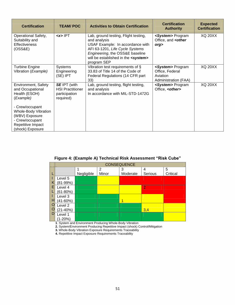
51
Certification TEAM/ POC Activities to Obtain Certification Certification
Authority Expected
Certification
Operational Safety, Suitability and Effectiveness (OSS&E)
<x> IPT Lab, ground testing, Flight testing, and analysis USAF Example: In accordance with AFI 63-1201, Life Cycle Systems Engineering, the OSS&E baseline will be established in the <system> program SEP
<System> Program Office, and <other org>
XQ 20XX
Turbine Engine Vibration (Example)
Systems Engineering (SE) IPT
Vibration test requirements of § 33.83 of Title 14 of the Code of Federal Regulations (14 CFR part 33)
<System> Program Office, Federal Aviation Administration (FAA)
XQ 20XX
Environment, Safety and Occupational Health (ESOH) (Example) - Crew/occupant Whole-Body Vibration (WBV) Exposure - Crew/occupant Repetitive Impact (shock) Exposure
SE IPT (with HSI Practitioner participation required)
Lab, ground testing, flight testing, and analysis In accordance with MIL-STD-1472G
<System> Program Office, <other>
XQ 20XX
Figure 4: (Example A) Technical Risk Assessment “Risk Cube”
CONSEQUENCE
L I K E L I H O O D
1 Negligible
2 Minor
3 Moderate
4 Serious
5 Critical
Level 5 (81-99%)
Level 4 (61-80%)
2
Level 3 (41-60%)
1
Level 2 (21-40%)
3,4
Level 1 (1-20%)
1. System and Environment Producing Whole-Body Vibration 2. System/Environment Producing Repetitive Impact (shock) Control/Mitigation 3. Whole-Body Vibration Exposure Requirements Traceability 4. Repetitive Impact Exposure Requirements Traceability

52
Table 15: (Example A) Technical Risk Assessment - Mitigation
Technical Risk Assessment and Mitigation Plans (see Figure 4)
Technical Risk 1 System and Environment Producing Whole-Body Vibration
Description If the <system>, along with the operating environment cannot meet the requirements for exposure to WBV established in the <system> CDD and SRD, then unplanned design efforts will be required to achieve necessary performance.
Mitigation <TBD, insert here>
Driver (Risk 1) There are <system> requirements which limit crew/occupant exposure whole-body vibration; <Key System Attribute Threshold(s)> which must fall within defined “safe” risk ranges (magnitude and duration dependent). The <system> and/or its sub-systems needs to control/mitigate these energies from being produced and/or from being transferred (at the human-machine interfaces) to the crew/occupant (see CDD and SRD for requirement specifics).
Technical Risk 2 System/Environment Producing Repetitive Impact (shock) Control/Mitigation
Description If the <system>, along with the operating environment cannot meet the requirements for exposure to repetitive impact (or shock) established in the <system> CDD and SRD, then unplanned design efforts will be required to achieve necessary performance.
Mitigation <TBD, insert here>
DRIVER (Risk 2) There are <system> requirements which limit crew/occupant exposure repetitive impacts (shock); <Key System Attribute Threshold(s)> which must fall within defined “safe” risk ranges. The <system> and/or its sub-systems needs to control/mitigate these energies from being produced and/or from being transferred (at the human-machine interfaces) to the crew/occupant (see CDD and SRD for requirement specifics).
Technical Risk 3 Whole-Body Vibration Requirements Traceability
Description If the <system> Whole-Body Vibration (WBV) requirements <e.g. CDD Key System Attribute Threshold/Objective values; measurement/verification> are not properly documented in the SRD, then confusion will result, extending the time required for the contract award or adding to the challenges in passing the System Requirements Review, with the possibility of contract changes to attain the needed capability, or risk of the requirement being overlooked or dropped.
Mitigation <TBD, insert here>
DRIVER (Risk 3)
The <system> will itself produce and operate in environment in which create vibration energies which can be transferred to crew/occupants (whole-body vibration exposure). DoD Standards (and associated references) define general requirements for personnel exposure to whole-body vibration (in terms of magnitude and duration). The CDD clarifies Threshold and Objectives values, as well as provides measurement guidance. The developmental planning activity should understand the <blank> requirements and verification techniques for the <system> and assess the <system> capability in this technical area. The implications to <system> and/or sub-system design (e.g. crew stations, seats, etc.) need to be assessed and scoped.
Technical Risk 4 Repetitive Impact Exposure Requirements Traceability
If the repetitive impact (shock) requirements <e.g. CDD Key System Attribute Threshold/Objective value; measurement/verification> are not properly documented in the SRD, then confusion will result, extending the time required for the contract award or adding to the challenges in passing the System Requirements Review, with the possibility of contract changes to attain the needed capability, or risk of the requirement being overlooked or dropped.
Mitigation <TBD, insert here>
DRIVER (Risk 4)
The <system> operating environment can expose crews/occupant to extreme impact energies (which can be transferred to crew/occupants). DoD Standards (and associated references) define requirements for personnel exposure to impact energy. The developmental planning activity should understand the <blank> requirements for the <system> and assess the <system> capability in this technical area. The implications to <system> and/or sub-system design (e.g. crew stations, seats, etc.) need to be assessed and scoped.

53
Table 16: (Example B) Technical Risk Assessment – Mitigation Table
No risk cube for Example B
# Risk Description Pre-Mitigation Parametric
(Likelihood/ Consequence)
Mitigation Strategy
<unique identifier>
<system> produces excessive vibration (excluding additional environment factors); at human interfaces; exceeds WBV exposure limits (magnitude-duration)
(2/3) - Utilize systems engineering strategies (design) to isolate, attenuate, damp vibration contributors down to the component level (system producing vibration) - Incorporate active vibration damping in SE / design
<unique identifier>
Legacy seating system design approach incapable of mitigating combined vibration (both system and environment induced), and/or transferred to operator; to within safe WBV exposure zone(s) for operations environment (magnitude) and expected mission durations (duration).
(4/4) - Mitigation plan in work; - Seating system designed with tuned vibration isolation / dampers, etc. - Add vibration damping seat padding -SE IPT to include Human Systems Integration (HSI) practitioners with access to vibration/impact expertise - ensure high visibility and technical insight to this special set of Key System Attributes (requirements)
<unique identifier>
<system> incapable of mitigating repetitive impact (shock) loads to crew/occupants to safe levels <KSA _______ (T)>, in operating environment, system use-cases, mission CONOPS, etc.
(4/4) - SE IPT to include Human Systems Integration (HSI) practitioners with access to vibration/impact expertise throughout the development and acquisition cycle - ensure high visibility and technical insight to this special set of Key System Attributes (requirements)
<unique identifier>
<system> and subsystems <seats, suspension seats, support systems, other designs> incapable of mitigating impact energies (shock) to occupants; to KSA Threshold (T) required health risk ranges (in expected extreme operational environments, use-cases).
(4/4) SE IPT to include Human Systems Integration (HSI) practitioners with access to vibration expertise throughout the development and acquisition - ensure high visibility and technical insight to this special set of Key System Attributes (requirements) - Incorporating tuned support and seating system technology <suspension seats, isolation, damping, etc.> in crew station design Mitigation plan in work
<unique identifier>
Whole-Body Vibration (WBV) <or> repetitive impact (shock) exposure requirements may get confused at the SRD level; potentially deleted, or adding challenges to smooth contract award and requirements interpretation by developing organization - corrupting the requirement(s) in System and Subsystem Specification (SSS) or WSS.
(4/3) - SE IPT to include Human Systems Integration (HSI) practitioners with access to vibration/impact expertise, Lab personnel - ensure high visibility and technical insight to this special set of Key System Attributes (requirements)

54
# Risk Description Pre-Mitigation Parametric
(Likelihood/ Consequence)
Mitigation Strategy
<unique identifier>
Limited developmental and operational testing resources for Whole-Body Vibration (WBV) <or> repetitive impact (shock) exposure requirements; specifically in extreme environments and use-cases.
(5/2) Mitigation plan in work
<unique identifier>
Design calculations and related testing may not consider predictable performance degradation of vehicle suspension and seating system resiliency over time between required maintenance evolutions. Design should consider not only new optimally performing systems, but wear-related reduction in vibration attenuation.
(4/3) - SE IPT to include Human Systems Integration (HSI) practitioners with access to vibration/impact expertise, Lab personnel - ensure high visibility and technical insight to this consideration
Table 17: (Example Table) <program> Integrated Product Team (IPT) Details
Team Name
Chairperson Team Membership Team Role, Responsibility
and Authority Products and Metrics
<system, program, element> IPT
<system, program, element> IPT Lead
Program Office - Hardware Engineer - <x> Engineer - <x> Engineer - Software Engineer - Configuration Control - Test Engineer - System Security
Engineer - MFG/QA - Sustainment/ R&M - Training Systems - Human Systems
Integration Engineer-Practicioner
Role: - Manage Engineering <x> - Responsibilities: Ensure
require-ments are flown down to contractor
- Ensure as-built software meets allocated require-ments
- Maintain System security certifica-tion
- Maintain Inter-operability certification
- Ensure Human-System Integration (HSI) considerations are implemented in Designs
Products: - Training System
Update - T.O. Updates Metrics: - TPM’s - Deficiency Reports - Contractor Problem
Reports (open, closed, total)
- Earned Value Management (EVM) status
- Staffing - Risks

55
Table 18: Example TPMs Table
Risk Number
Risk Notional TPM(s) Notional Measure (s)
1 System and Environment Producing Whole-Body Vibration
Vibration Transfer (Magnitude), Vibration Control Performance (Nominal, Extreme X, Extreme Y, Extreme Z)
Margin
Hz, Root Mean Square (RMS) Acceleration, Vibration Dose Value (VDV), Acceleration, etc.
2 System/Environment Producing Repetitive Impact (shock) Control/Mitigation
Impact/Shock Load-Energy Transfer (Magnitude), Impact/Shock Control Performance (Nominal, Extreme X, Extreme Y, Extreme Z)
Margin
MPa, Daily Equivalent Static Compression Dose (Sed), Normalized Acceleration Dose (Dkd), Acceleration Dose (Dk), Magnitudes and Peaks, etc.
3 Whole-Body Vibration Exposure Requirements Traceability
N/A N/A
4 Environmental Control System Performance
N/A N/A
Table 19: Example SEP Section 4: Table 4.6-1
Name Cognizant PMO
Organization
Certification Document CDRL # Description/Comments
Accessibility
-DODI 5000.02: N/A
-DAG: 4.4.1
-Service Specific Guidance
-Other: Section 508 of rehabilitation Act of 1973
SE IPT (HSI) N/A SOW: TBD
SRD: TBD
TBD for System>
TBD
Critical Safety Items
-DODI 5000.02: N/A
-DAG: 4.4.4
-Service Specific Guidance
SE IPT
ILST
Airworthiness Certification
Airworthiness Plan
SOW: TBD
SRD: N/A
TBD for System>
See “ESOH” of this Table.
ESOH
-DODI 5000.02: Table 2 & Enclosure 12
-DAG: 4.4.7 & 6.3.5
-Other: NEPA & EO 12114; MIL-STD-882D
-Service Specific Guidance (e.g. AFI 63-1201 or
SE IPT (HSI & System Safety WG)
N/A PESHE
SOW: TBD
SRD: paragraph X
<TBD for System>
The <system, program> Lead Systems Engineer will work in conjunction with the <system, program> PM and <system, program> IPTs to oversee and guide integration of ESOH considerations into the SE process for the <system, program> system. An ESOH Lead and a System Safety Engineer Lead (Principal for Safety) will be appointed by the <system, program> PM to execute the day-to-day requirements of the <system, program> ESOH

56
Name Cognizant PMO
Organization
Certification Document CDRL # Description/Comments
AFI 63-101), (OPNAVINST 5100.24B)
Program.
The <system, program> Program’s ESOH risk assessment process is based on the premises of Military Standard-882D, whereby ESOH hazards and their associated risks are managed where they cannot be eliminated through design. In addition, the <system, program> Program is using the <X; e.g. AF ESOH Programmatic Risk Toolset> to gauge potential ESOH programmatic risks. All identified ESOH hazards and their associated risks will be tracked and managed to closure by the ESOH and System Safety Engineer Leads for the <system, program> Program. The analyzed ESOH hazards will be entered into a hazard-tracking database showing each hazard’s unique identification number, short title, mishap risk assessment value, and status.
PMs, regardless of the Acquisition Category of their programs, integrate system safety risk management into their overall systems engineering and risk management process. PMs must ensure the requirement to integrate the ESOH risk management strategy into the systems engineering process is incorporated in the SEP.
Ensure that exposure to whole-body vibration and the mitigation of whole-body vibration is cited as part of relevant safety requirements.
Ensure that exposure to repetitive impact (or shock) and the mitigation of such exposure is cited as part of relevant safety requirements.
Add whole-body vibration (and applicable designations) as a KSA, Additional Performance Attributes, or at a minimum, Other System Attributes and give appropriate priority to the list of requirements.
For further information on <system, program’s> approach and plans for ESOH analyses, please see the <system, program’s> Programmatic Environment, Safety, and Occupational

57
Name Cognizant PMO
Organization
Certification Document CDRL # Description/Comments
Health Evaluation, which can be found at [TBD link]
HSI
-DODI 5000.02: Enclosure 8
-DAG: 4.4.8 & Chapter 6
-Other: 5000.01, E1 1.29
-MIL-STD-1472G
-Service Specific (e.g. AFI 63-1201 or AFI 63-101)
SE IPT (HSI) N/A HSI Plan – SEP Attachment
SOW: TBD
SRD: HSI implications throughout the SRD
SRD: 3._._.X
SRD: 3._._.X
TBD for System>
Human factors engineering. Where applicable, this paragraph should specify human factors engineering requirements for the entity, including any special or unique requirements (for example, constraints on allocation of functions to personnel, interactions of communications and of personnel with equipment). Included should be those specified areas, stations, or equipment that requires concentrated human engineering attention due to the sensitivity of the operation or criticality of the task, particularly those areas where the effects of human error would be particularly serious. These requirements should include, as applicable, considerations for: a. Human information processing capabilities and limitations. b. Foreseeable human errors under both normal and extreme conditions (especially for input, display, control, maintenance and management of critical information and systems).
c. Implications for the total system environment (including training, support, and operational environment).
OSS&E
-DODI 5000.02: N/A
-DAG: N/A
-Service Specific Guidance
-Other
SE IPT
ILST
Airworthiness Certification
OSS&E Baseline Document (TBD)
SOW: TBD
SRD: N/A
TBD for System>
<X>
Survivability and Susceptibility
-DODI 5000.02::
-DAG: 4.4.20
-Service Specific Guidance
-Other
SE IPT
HSI HG (for Crew and Passenger Survivability)
N/A LFT&E Plan
LFT&E Report
SOW: TBD
SRD: N/A
TBD for System>
System Safety SE IPT See Comment
See Comment
See Comment
See “Critical Safety Items” of this Table.
Total Ownership Cost
-DODI 5000.02:
-DAG
-Service Specific Guidance
-Other
ILST See Comment
See Comment
See Comment
Included in <X>
Safety, Occupational Health concerns if not addressed (vibration-impact; KSA ____, OSA _____) will increase Total Ownership Cost (medical costs for occupational health issues / back, neck, and musculoskeletal injury to crewmembers and passengers.

58
Name Cognizant PMO
Organization
Certification Document CDRL # Description/Comments
Training
-DODI 5000.02:
-DAG
-Service Specific Guidance
-Other
ILST See Comment
See Comment
See Comment
Included in <blank>
<System Vibration <and/or> Repetitive Impact Control/mitigation>
-DODI 5000.02:
-DAG:
-MIL-STD-1472G; 5.5.5.
-Service Specific Guidance
-Other:
SE IPT (HSI & System Safety WG)
<if/as applicable>
HSI Plan, PESHE, OSS&E Baseline Document (TBD),
etc.
SOW: TBD
SRD: 3._._.X
SRD: 3._._.X
SRD: 3._._.X
SRD: 3._._.X
TBD for System>
The HSI/ESOH Lead and a System Safety Engineer Lead (Principal for Safety), appointed by the <system> PM to execute the day-to-day requirements of the <system, program> ESOH Program, will ensure MIL-STD-1472, Section 5.5.5.-based requirements (see KSA ___) are accurately documented SRD, and accurately translated to development contract, System and Subsystem Specification (SSS) - contractor functional baseline.
Table 20: Other CDD Notes and Guidance
Depending upon the Program Office approach, the SEP will have a Programmatic Environment, Safety and Occupational Health Evaluation (PESHE) Plan as an attachment, Annex, and/or “link”
Depending upon the Program Office approach, the SEP may have a Human Systems Integration Plan as an attachment, Annex, and/or “link”

59
Test and Evaluation Master Plan (TEMP)
The suggestions, example language provided, and the placement of the language within the document(s) are presented as a reference for acquisition and other professionals. Examples are not necessarily meant to be specific for any particular type of system or acquisition program. Suggestions and examples provided are intended to assist acquisition professionals by providing a starting point for tailoring language unique to
individual development programs. Specific standards can be obtained from an HSI practitioner or from any of the sources identified in the Standards and/or References tab.
The TEMP documents the overall structure and objectives of the Test & Evaluation (T&E) program. It provides a framework to generate detailed T&E plans and documents schedules and resource implications associated with the T&E program. The TEMP identifies the necessary DT&E, OT&E, and Live Fire Test and Evaluation (LFT&E) activities. It relates program schedule, test management strategy and structure, and required resources to Critical Operational Issues (COIs), CTPs, objectives, and thresholds documented in the Capabilities Development Document (CDD), evaluation criteria, and milestone decision points. The TEMP does not relieve the contractor of any contractual obligations. It serves as an indicator of government expectations, and should complement, not contradict, specifications and contractual language. The government TEMP should be shared with industry as appropriate. Sharing the TEMP pays dividends and should be a common practice as appropriate to contractual T&E responsibilities (e.g., a single prime contractor responsible for all T&E).
TEMP Model Language for Whole-Body Vibration (WBV) and/or Repetitive Impact This section provides general guidance and some model language to address WBV and/or repetitive impact within a TEMP. Information in the form of Section Notes or Guidance may be provided which is generally applicable to the TEMP Section identified. These sections may include Example Tables or other information (with WBV and/or Impact examples), presented in a TEMP-representative format. The examples and formats provided will vary, in order to present the user with broad options and a general starting point for a TEMP intended to incorporate WBV and/or repetitive impact as an important attribute(s). The user of this Guide is reminded that the information provided is intended to assist in “crafting” or “tailoring” language most appropriate to their particular program or set of circumstances, not to be a direct “cut-and-paste” solution.
- KEY -
<…> “Insert Applicable Information Here” (i.e. <x>, <X>, <Y>, <Z>, etc.)
<name, value, other>… Same as Above with category or example of information needed
6._._.G-x Placeholder: example “unique identifier” for example language
“SPS” and “SRD” A “System Performance Specification (SPS)” and a “System Requirements Document (SRD)” are nominally the same document/artifact, and within this QRG, may be used interchangeably.
References to “HSI” “ESOH” WBV and/or repetitive impact exposure (mitigation/reduction) is an “implied” consideration
Test & Evaluation Master Plan
(TEMP) Home

60
Table 21: TEMP Section
Document TEMP Notes / Guidance
TEMP
Most all sections of the TEMP are relevant to Human Systems Integration (HSI) considerations (such as a development system with priority given to addressing whole-body vibration and repetitive impact exposure of human occupants).
For consistency in this QRG section, unless otherwise indicated, example language provided in select TEMP sections below will generally be in the context of an upgrade to a fictional (or simulated) land-based, 4-wheeled, troop carrying, all-terrain type vehicle; with a simulated “deficiency” in the legacy system being addressed by this “upgrade” - excessive WBV and repetitive impact energy exposure for the system crew and its occupants.
Sections numbering beyond the primary section number are not further delineated as TEMP documents (subsections) may vary between Services, or programs.
Document Section Section Notes / Guidance
TEMP Section 1.x
Introduction – System Description
Include HSI considerations (WBV, impact) where and as appropriate throughout Section 1.0, especially if a consideration such as WBV and/or repetitive impact has a high program priority (has own KSA or other system attribute requirement(s), linked to system measures of performance/effectiveness, and/or is or is associated with an identified capability gap or deficiency being overcome).
Document Section Example Language
TEMP Section 1.x
System Description
The approved Initial Capabilities Document (ICD), <date>, describes the <modernization, recapitalization, and transformation> requirements for modernizing the <x vehicle, platform, fleet> from the present to 2020 and beyond. The <program> is intended to fill capability gaps identified by the combat developers in the Functional Needs Analysis (FNA). These ICD capability gaps are defined as:
· Gap <x> - Inability to <perform desired mission, or mission duration, within crew/occupant safe exposure limits for WBV and/or repetitive impact loads>
The <system> will be designed to overcome these capability deficiencies, and provide operational capability for present and future requirements. The <system> must be capable of operating and surviving across <range of operations>, threat and climatic environments. To this end, the <system> will be a <x vehicle> incorporating design features to meet the survivability, habitability, deployability, agility, versatility, net-centricity, and sustainability requirements of <y> forces employed across the <range of operations>.
The system is also designed to overcome a deficiency in legacy systems by reducing to safe ranges, the exposure of crewmembers and vehicle occupants to <WBV and/or repetitive impact loads – transferred at interfaces> throughout the mission profiles and durations.
This TEMP describes planned developmental, integrated, operational, and live-fire testing including measures to evaluate the performance of the system during these test activities; an integrated test schedule; and the resource requirements to accomplish the planned testing.

61
Document Section Example Language
TEMP Section 1.x
Operational Environment
(notional examples)
Current events and projections of tomorrow’s global environment require US forces and our allies to operate in potentially hostile regions across an extended battlefield. With limited and unpredictable access, military leadership must increasingly rely on expeditionary forces for quick response to developing crises. These operations require <long-range and high-speed mobility> capabilities in areas that often present a demanding challenge in the form of <restricting features such as those found in urban terrain or off-road environments>.
The <system> improves <HSI/HFE considerations; i.e. safety, occupational health, and crew/occupant fighting effectiveness> over legacy systems by reducing crew/occupant exposure to WBV and/or repeated impact loads (reduced fatigue, motion sickness incidence, injury) experienced in long-duration, rough terrain insertion-extraction ops.
The Concept of Operations (CONOPS) derived from <x> identifies the capabilities required across the Range of Military Operations (ROMO) in support of all Services. <x concepts> emphasize maneuver warfare and the ability to safely distribute forces over long distances and across variable terrain, while maintaining the crew/occupant/soldier ability to effectively engage the enemy across a broad operational battlespace (no loss in effectiveness due to fatigue, sickness, injury from <systems> operations).
Document Section Section Notes / Guidance
TEMP Section 1.x
Key Capabilities
Identify the Key Performance Parameters (KPPs) and Key System Attributes (KSAs) for the system, which include Threshold/Objective values for WBV and/or repetitive impact exposure. A separate table may be used similar to those in the CDD.
TEMP Section 1.x
Key Interfaces
Document all interfaces that involve humans. Ensure that time effects (e.g. fatigue, occupational health, prolonged exposure to environment) with regard to human-machine interfaces will be included in testing.
Document Section Example Language
TEMP Section 1.x
Key Interfaces
<system> operators and passengers must be able to remain seated within the <system> for <x hours> on <y terrain, environment conditions> without exceeding individual exposure limits to WBV (IAW MIL-STD-1472) in order to effectively perform dismounted mission at destinations (testing of WBV damping seats and other interfaces).
<system> operators and passengers must be able to efficiently function inside the <system> and be able to quickly mount and dismount with full combat gear, including protective gear (body armor and Mission Oriented Protective Posture (MOPP) gear.
Document Section Section Notes / Guidance
TEMP Section 1.x
Special Test or Certification Requirements
Ensure special test and evaluation assets (or techniques) required to verify/test for system (or subsystem) WBV mitigation capabilities and/or impact loads reduction are mentioned here (i.e. triaxial seat pan devices and data logging devices, special accelerometers, terrain test track access, representative operators, etc.)
Ensure WBV and/or repetitive impact subject matter experts are assigned to the team responsible for developing special test and evaluation assets and techniques (i.e. derived testing techniques for magnitude-duration exposure techniques related to WBV or impact)

62
Document Section Example Language
TEMP Section 1.x
Special Test or Certification Requirements
There are a number of sub-systems that will be developed by the vendor specifically for the <system>, e.g. <active/passive vibration systems for> crew and occupant seat in systems within the vehicle. The <system> will have on-platform vehicle diagnostic and health monitoring capability <incl ride quality monitoring/status> which will enable collecting embedded data and pending maintenance within the vehicle health management system.
Special testing considerations will be required for COTS hardware/software in crew compartment subsystems (seats, seating systems, energy damping technologies). The HSI and ESOH Working Groups will be responsible for establishing these special test/evaluation procedures to ensure compliance with MIL-STD-1472 and associated Standards (ISO 2361) and any program-pecific variations.
Document Section Section Notes / Guidance
TEMP Section 2.x
T&E Management – T&E Org. Construct
Ensure that an HSI subject matter expert (and/or WBV and impact specialist/scientist) is assigned to the integrated test team or sub-work groups (the government developmental test team)
Document Section Example Language
TEMP Section 2.x
T&E Management – T&E Org. Construct
Human System Integration (HSI) WG
The HSI WG, a sub-group under the <SE> IPT, will ensure the program focuses on the integration of human considerations into the system acquisition process to enhance system design, reduce life cycle ownership costs, and optimize total system performance. The HSI WG accomplishes this by ensuring the “human” is fully and continuously considered as part of the total system in the development and/or acquisition of all systems. Human performance is a key factor in “total system performance,” and enhancements to human performance will correlate directly to enhanced total system performance and help reduce life cycle ownership costs. In addition to all other HSI domains, an important consideration for this <system> (high priority; see KSAs, Other System Attribute, etc.) is the operational employment of <system> while maintaining safe (within limits) human (crew/occupant) exposure to WBV and/or repetitive impacts (see also ESOH WG).
Environmental, Safety, and Occupational Health (ESOH) WG
The ESOH WG, a sub-group under the <SE IPT, working directly with HSI WG>, will ensure the program eliminates or controls system hazards to minimize injury to the user, maintainer and the environment. The specific responsibilities include:
Identifies and develops system safety and environmental requirements
Clarifies Regulations regarding Environmental, Safety, and Occupational Health
Provides guidance in ensuring ground vehicle safety in all environments against the full spectrum of safety issues including front and side impact crashes, roof crush, vehicle rollover, fire suppression, and crew seating issues (including; WBV and/or repetitive impact exposure IAW MIL-STD-1427G)
Provide measurement, verification/testing procedures for WBV <and/or repetitive impact> exposure <KSA, additional, other system attribute> of <system>
Assesses the ground vehicle safety design to ensure that safety requirements of the overall system are met
Documents and tracks hazards identified in design or testing
Tracks materials usage through vendor prepared Hazardous Materials Management Reports (HMMR) and work to identify alternatives
Develops System Safety Risk Assessments (SSRAs) IAW MIL-STD 882E
Provides potential design changes to reduce or eliminate risk
Provides a forum for the in-depth discussion

63
Document Section Section Notes / Guidance
TEMP Section 2.x
Common T&E Database, Deficiency Reporting
Test and verification techniques (including data collection) for WBV and/or repetitive impact within a development system/program may be fairly complex (program-specific techniques may be needed). The Standards and other associated guidance provide a framework from which to work, although system or program-unique missions, environments, and requirements may dictate variations to the framework best suited to the system and environment (as initially outlined by MIL-STD-1472G environment category/categories, and associated standards). The T&E team and sub-working groups (both government and contractor) must be coordinated to ensure methods of collecting, validating, and sharing test and evaluation data effectively.
Document Section Example Language
TEMP Section 2.x
Common T&E Database, Deficiency Reporting
Deficiency reporting and tracking is an essential responsibility of the <system> Program Office. The <system> test team has implemented a standardized deficiency reporting and tracking system as mutually agreed upon by <x, y, z organizations>.
Deficiencies and reliability failures uncovered during government testing will be documented in daily reports as well as Test Incident Reports (TIRs). Daily reports and data will be accessible through <system, process>. TIRs will be processed….
Document Section Section Notes / Guidance
TEMP Section 2.x
Integrated Test Program Schedule
Ensure significant WBV and/or repetitive impact verification/testing events are included in the integrated master schedule (e.g. development and approval of the measurement and assessment techniques specific to WBV and/or impact exposures to human crew/occupants, test article(s) availability, test tracks/environment availability, etc.)
Document Section Section Notes / Guidance
TEMP Section 3.x
Test and Evaluation Strategy
This section should summarize an effective and efficient approach to the test program.
Address how the test objectives will be integrated to support the acquisition strategy by evaluating the capabilities to be delivered to the user without compromising the goals of each major kind of test type.
Evaluations shall include a comparison with current mission capabilities using existing data, so that measurable improvements can be determined. If such evaluation is considered costly relative to the benefits gained, the PM shall propose an alternative evaluation strategy for achieving this comparison.
Mission-Oriented Approach: Describe the approach to evaluate the system performance in a mission context during DT in order to influence the design, manage risk, and predict operational effectiveness and operational suitability.
Document Section Section Notes / Guidance
TEMP Section 3.x Test and Evaluation Strategy
(Evaluation Framework)
An Example Top-Level Evaluation Framework Matrix is provided below, showing only notional WBV and/or repetitive impact information associated with a “fictional” ground vehicle. See table 22 at the end of the TEMP section.
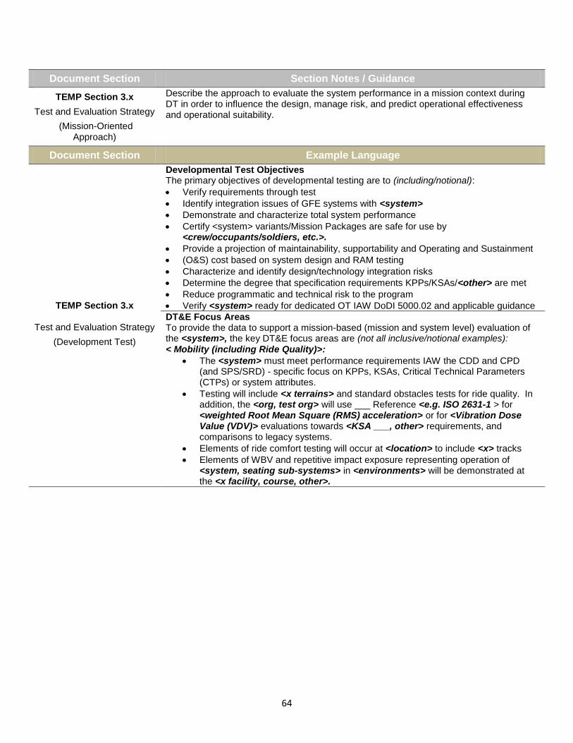
64
Document Section Section Notes / Guidance
TEMP Section 3.x
Test and Evaluation Strategy
(Mission-Oriented Approach)
Describe the approach to evaluate the system performance in a mission context during DT in order to influence the design, manage risk, and predict operational effectiveness and operational suitability.
Document Section Example Language
TEMP Section 3.x
Test and Evaluation Strategy
(Development Test)
Developmental Test Objectives The primary objectives of developmental testing are to (including/notional):
Verify requirements through test
Identify integration issues of GFE systems with <system>
Demonstrate and characterize total system performance
Certify <system> variants/Mission Packages are safe for use by <crew/occupants/soldiers, etc.>.
Provide a projection of maintainability, supportability and Operating and Sustainment
(O&S) cost based on system design and RAM testing
Characterize and identify design/technology integration risks
Determine the degree that specification requirements KPPs/KSAs/<other> are met
Reduce programmatic and technical risk to the program
Verify <system> ready for dedicated OT IAW DoDI 5000.02 and applicable guidance
DT&E Focus Areas To provide the data to support a mission-based (mission and system level) evaluation of the <system>, the key DT&E focus areas are (not all inclusive/notional examples): < Mobility (including Ride Quality)>:
The <system> must meet performance requirements IAW the CDD and CPD (and SPS/SRD) - specific focus on KPPs, KSAs, Critical Technical Parameters (CTPs) or system attributes.
Testing will include <x terrains> and standard obstacles tests for ride quality. In addition, the <org, test org> will use ___ Reference <e.g. ISO 2631-1 > for <weighted Root Mean Square (RMS) acceleration> or for <Vibration Dose Value (VDV)> evaluations towards <KSA ___, other> requirements, and comparisons to legacy systems.
Elements of ride comfort testing will occur at <location> to include <x> tracks
Elements of WBV and repetitive impact exposure representing operation of <system, seating sub-systems> in <environments> will be demonstrated at the <x facility, course, other>.
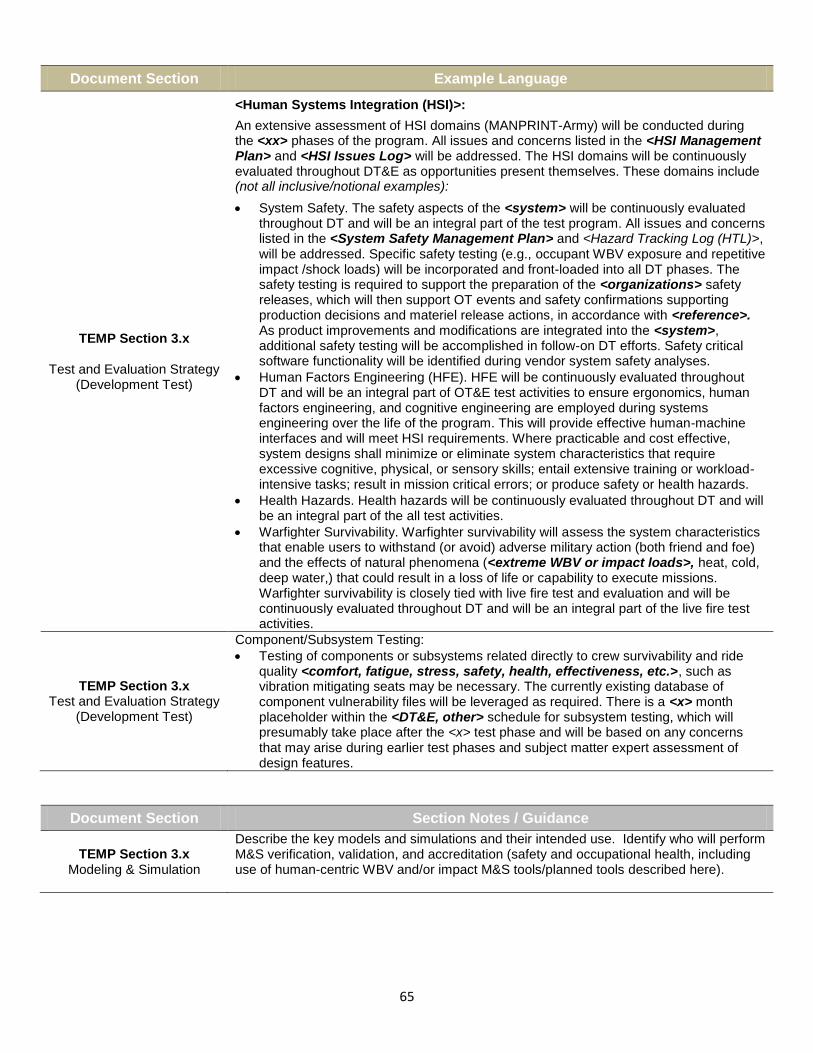
65
Document Section Example Language
TEMP Section 3.x
Test and Evaluation Strategy (Development Test)
<Human Systems Integration (HSI)>:
An extensive assessment of HSI domains (MANPRINT-Army) will be conducted during the <xx> phases of the program. All issues and concerns listed in the <HSI Management Plan> and <HSI Issues Log> will be addressed. The HSI domains will be continuously evaluated throughout DT&E as opportunities present themselves. These domains include (not all inclusive/notional examples):
System Safety. The safety aspects of the <system> will be continuously evaluated throughout DT and will be an integral part of the test program. All issues and concerns listed in the <System Safety Management Plan> and <Hazard Tracking Log (HTL)>, will be addressed. Specific safety testing (e.g., occupant WBV exposure and repetitive impact /shock loads) will be incorporated and front-loaded into all DT phases. The safety testing is required to support the preparation of the <organizations> safety releases, which will then support OT events and safety confirmations supporting production decisions and materiel release actions, in accordance with <reference>. As product improvements and modifications are integrated into the <system>, additional safety testing will be accomplished in follow-on DT efforts. Safety critical software functionality will be identified during vendor system safety analyses.
Human Factors Engineering (HFE). HFE will be continuously evaluated throughout DT and will be an integral part of OT&E test activities to ensure ergonomics, human factors engineering, and cognitive engineering are employed during systems engineering over the life of the program. This will provide effective human-machine interfaces and will meet HSI requirements. Where practicable and cost effective, system designs shall minimize or eliminate system characteristics that require excessive cognitive, physical, or sensory skills; entail extensive training or workload-intensive tasks; result in mission critical errors; or produce safety or health hazards.
Health Hazards. Health hazards will be continuously evaluated throughout DT and will be an integral part of the all test activities.
Warfighter Survivability. Warfighter survivability will assess the system characteristics that enable users to withstand (or avoid) adverse military action (both friend and foe) and the effects of natural phenomena (<extreme WBV or impact loads>, heat, cold, deep water,) that could result in a loss of life or capability to execute missions. Warfighter survivability is closely tied with live fire test and evaluation and will be continuously evaluated throughout DT and will be an integral part of the live fire test activities.
TEMP Section 3.x Test and Evaluation Strategy
(Development Test)
Component/Subsystem Testing:
Testing of components or subsystems related directly to crew survivability and ride quality <comfort, fatigue, stress, safety, health, effectiveness, etc.>, such as vibration mitigating seats may be necessary. The currently existing database of component vulnerability files will be leveraged as required. There is a <x> month placeholder within the <DT&E, other> schedule for subsystem testing, which will presumably take place after the <x> test phase and will be based on any concerns that may arise during earlier test phases and subject matter expert assessment of design features.
Document Section Section Notes / Guidance
TEMP Section 3.x Modeling & Simulation
Describe the key models and simulations and their intended use. Identify who will perform M&S verification, validation, and accreditation (safety and occupational health, including use of human-centric WBV and/or impact M&S tools/planned tools described here).

66
Document Section Example Language
TEMP Section 3.x Modeling & Simulation
<simulator, tool name>: The <x simulator, M&S tool> is designed to accommodate testing of vehicle dynamics, powertrain performance, and shock and vibration testing in a laboratory environment. The <x test system, M&S tool> may be used: when field testing cannot be conducted due to inclement weather conditions; when needed to provide the fidelity required to address a complex issue; or in the event driver safety is a concern. Those <x simulator, M&S tool> tests that have been validated through the Verification and Validation (V&V) process will be considered for accreditation and use in this phase of the program.
<model name> is a <human figure model> that uses Computer Aided Design (CAD) drawings of a system to assess HFE concerns such as ability of personnel to occupy crew work stations, use controls, and fit in and out of hatches wearing various ensembles. Since it is a computer model, it enables identification of HFE challenges very early during materiel acquisition, precluding the necessity of costly and time consuming modifications to vehicle prototypes or production vehicles. <model name> will be used during the
<x> phase of the program <or y phase of the testing> for the purpose of assessing the ability of central 90th percentile personnel to operate and maintain the system, and identify any potential design challenges interfering with operating and maintain the system.
<x> will be used as representative individual (90th percentile person) if/when testing
for WBV and/or repetitive impact loads becomes a safety concern for actual personnel.
Document Section Section Notes / Guidance
TEMP Section 3.x Operational Test and Evaluation Objectives
State the key MOEs/MOSs that support the COIs/COICs. Describe the scope of the operational test(s) by identifying the test mission scenarios and the resources that will be used to conduct the test(s).
Quantify the testing sufficiently (e.g. number of hours, test articles, events, to allow a valid cost estimate to be created).
Identify and develop plans to address any HSI issues (such as WBV and/or impact exposure considerations) from previous acquisition phases.
If there are new Manpower/Personnel/Training requirements due to the new capability, ensure all are addressed in a timely manner to guarantee the test team is truly “representative”.
Document Section Example Language
TEMP Section 3.x Operational Test and Evaluation Objectives
Operational Test and Evaluation Objectives
The objective of OT&E is to provide data on the effectiveness and suitability of the <system> when employed by trained units. A Limited User Test (LUT) will be conducted in the <x> phase of the program. The LUT will be conducted to provide data on the initial assessment of operational effectiveness and suitability of <x designs; e.g. multiple vendor designs, etc.> and to identify potential operational deficiencies and opportunities for improvement before the PD phase.
The <organization(s)> will execute the Limited User Test (LUT) events in accordance with the approved Operational Test Agency Test Plan. The purpose of the LUT events is to provide input to the <___> on the initial effectiveness and suitability of the <system> to support the <e.g. Milestone or other> decision. The assessment of operational effectiveness and suitability will focus on the comparison of actual mission accomplishment of the units equipped with the <system> under a mission scenario, as compared to the baseline <or legacy system name>-equipped unit. The LUT events will provide data on the system’s progress towards satisfying the <system> operational requirements and COICs.

67
Document Section Example Language
TEMP Section 3.x Operational Test and Evaluation Objectives
(Scope)
Assessments will be developed and implemented in OT&E to assess representative <crew/occupant/soldier> ability to perform mission-representative tasks <e.g. engaging hostile targets in <x> proximity, retrieving high-value assets or extracting personnel, etc.> following an operationally representative (speed, high vibration/impact conditions, <x> duration) drive/traverse across combat representative terrain conditions (max allowable).
MANPRINT/HSI and reliability data, as well as the <crew/occupant/soldier> assessments of their ability to operate the <system> safely, will be collected (e.g., operator assessment of vehicle drivability, safety of operation, ride quality (vibration) and HFE focused data collection).
Document Section Section Notes / Guidance
TEMP Section 4.x Resource Summary
In this section, specify the resources necessary to accomplish the T&E program. Testing will be planned and conducted to take full advantage of existing DoD investment in ranges, facilities, and other resources wherever possible.
Consider all HSI implications throughout this section (i.e. requirements specific to the complex task of T&E for system-crew/occupant WBV and/or repetitive impact exposure).
Table 22: Key Requirements and T&E Measures
Key Requirements and T&E Measures Test Methodologies/Key Resources
Decision Supported
Test Event
Enabling Capability (Key Req)
COIs Key MOEs/MOSs
CTPs & Threshold
KSA #3.x: Whole-Body Vibration, Impact Exposure
COI #x Force Protection
COI #x Mobility
(sufficient to execute unit mission in relevant environments)
MOE 2.x: Vehicle design; crew/occupant physical interfaces
Percent of WBV/impact within MIL-STD-1472G safe ranges/ thresholds met
The <system> shall be capable of <mission performance, duration, other parameters, etc.> with occupant WBV, impact/shock exposure values <blank, values, units> less than <blank>, and for <blank> duration (T) (See CDD #6.x.x., SRD#___ for thresholds)
Crew compartment (meet MIL-STD-1472G)
Human Factors analysis
Representative occupant and environment (terrain) testing, augmented by M&S
Performance Testing (Triaxial seat pad instrumentation)
<crew/occupant/soldier> assessments
PDR
CDR
MS-C
DT
L.U.T.
OT
Table 23: Other TEMP Notes / Guidance
Most all sections of the TEMP are relevant to Human Systems Integration (HSI) considerations. If made a program priority (such as a KSA-level requirement), testing and evaluation factors of whole-body vibration and repetitive impact exposure attributes within a development system will need significant representation in the TEMP.

68
System Performance Specification (SPS)
or *System Requirements Document (SRD)
The suggestions, example language provided, and the placement of the language within the document(s) are presented as a reference for acquisition and other professionals. Examples are not necessarily meant to be specific for any particular type of system or acquisition program. Suggestions and examples provided are intended to assist acquisition professionals by providing a starting point for tailoring language unique to
individual development programs. Specific standards can be obtained from an HSI practitioner or from any of the sources identified in the Standards and/or References tab. Used during source selection, an SPS (*may be referred to as a System Requirements Document) documents the warfighter capabilities in contractual language. An SPS is prepared early during RFP development and is normally based upon a capabilities document. The SPS is derived from the Concept of Operations (CONOPS), system-level performance metrics, mission threads/use cases, and usage environment and is developed by the program office. The SPS translates required warfighter capabilities into system/subsystem acquisition requirements addressing such concerns as performance; supportability; physical and functional integration; human system integration; security, test and evaluation; quality assurance; hardware; software; etc. The SPS is used by the program office to provide more detailed requirements than what's provided in a Capability Development Document (CDD) and should be finalized prior to contract award. Once the SPS or SRD (or preliminary) is placed on contract, the contractor will further develop the specification and develop their own, more detailed requirements document; often called a System or Subsystem Specification (SSS). The System or Subsystem Specification (SSS) forms a basis for Test and Evaluation (T&E) of the resultant system or subsystem.
SPS/SRD Model Language for Whole-Body Vibration (WBV) and/or Repetitive Impact This section provides model language (examples / statements) to address WBV and/or repetitive impact. Information in the form of Section Notes or Guidance may be provided which is generally applicable to the SPS or SRD Section identified. These sections may include Example Tables or other information (with WBV / Impact examples), presented in an SPS or SRD-representative format (aligned with MIL-STD-961E Defense and Program-Unique Specifications Format and Content). The example language provided will vary, in order to present the user with broad options and a general starting point for an SPS intended to incorporate WBV and/or repetitive impact as an important attribute(s). The user of this Guide is reminded that the information provided is intended to assist in “crafting” or “tailoring” language most appropriate to their particular program or set of circumstances, not to be a direct “cut-and-paste” solution.
- KEY -
<…> “Insert Applicable Information Here” (i.e. <x>, <X>, <Y>, <Z>, etc.)
<name, value, other>… Same as Above with category or example of information needed
6._._.G-x Placeholder: example “unique identifier” for example language
* “SPS” or “SRD” A “System Performance Specification (SPS)” and a “System Requirements Document (SRD)” are nominally the same document/artifact, and within this QRG, may be used interchangeably.
References to “HSI” “ESOH” WBV and/or repetitive impact exposure (mitigation/reduction) is an “implied” HSI and ESOH consideration
System Performance Specification (SPS) or System Requirements Document (SRD)
Home

69
Table 24: SPS or SRD Section
Document Notes / Guidance
SPS or SRD
SPS/SRD contents will be incorporated into the contract; describes the operational characteristics desired for an item without dictating how the item should be designed or built.
Section 3 of the SPS/SRD documents these system capability attributes and associated thresholds and objectives.
Section 4 of the SPS/SRD contains verification provisions for each requirement (attribute).
Section 5 of the SPS/SRD contains a requirements traceability matrix that traces SRD requirements up to warfighter capability documents (JCIDS) and down to the hardware/software component that implements the requirement.
Section Notes / Guidance
SPS Section 3
System or Subsystem Requirements
The example language examples provided below are generally categorized in Air, Land, Sea, and General sections, however, they are not necessarily meant to be mutually exclusive, or applicable only to one particular type of vehicle or platform.
Document Section Example Language (Air Vehicles)
SPS Section 3 System or Subsystem
Requirements
(Air Vehicles)
3._._.A-1 The <system name> shall be designed to minimize system vibration and to control the transmission of whole-body vibration to crewmembers and passengers to levels that permit safe and effective operation as specified in MIL-STD-1472G, ISO 2631-1; 1997 (magnitudes and durations of exposure) – THRESHOLD = OBJECTIVE.
3._._.A-2 The seat shall promote good posture in the operational environment and for the duration of the mission by; providing uniform body support over the seat/occupant contact area (not causing “hot spots” to occur), not transmitting vibrations between <x> to <y> frequencies, exceeding <z> amplitudes (T), <mission duration/time parameters as required for WBV exposure calculation>, and providing back support to reduce lumbar loads and back muscle fatigue - THRESHOLD = OBJECTIVE.
3._._.A-3 The crewmember seats shall have an adjustable lumbar support (does not include <other, jump, stow-able, etc.> seats) - THRESHOLD = OBJECTIVE.
3._._.A-4 The <system name> at <system parameter x, y, z> shall have a Vibration Dose Value (VDV) of no more than <value & units> cumulative, while negotiating <environment, obstacles>, <value> times, at speeds up to and including <value>, for <duration>. (*VDV shall be calculated according to ISO 2631-1 1997) – THRESHOLD.
3._._.A-5 The <system name> at <system parameter x, y, z> should have a Vibration Dose Value (VDV) of no more than <value & units> cumulative, while negotiating <environment, obstacles>, <value> times, at speeds up to and including <value>, for <duration>. (*VDV shall be calculated according to ISO 2631-1 1997) – OBJECTIVE.
3._._.A-6 <vehicle, system name> seating systems shall be designed to mitigate or minimize the transmission of vehicle vibration and shock to the occupant. System resonances below 20 Hertz shall be avoided for Category A and B environments as specified in MIL-STD-1472G, Section 5.5.5., ISO 2631-1; 1997. Seating systems shall also minimize vibration in the operating frequency range of the vehicle. Where visual performance is critical, higher frequencies at the seatback and headrest shall be avoided or mitigated – THRESHOLD = OBJECTIVE.

70
Document Section Example Language (Air Vehicles)
SPS Section 3 System or Subsystem
Requirements
(Air Vehicles)
3._._.A-7 For missions lasting <value; e.g. 8.0> hours or less, the seat pan frequency weighted triaxial Root Mean Square (RMS) accelerations* in any orthogonal direction for any occupied space shall not fall within the “Health Risks are LIKELY” zone for Whole-Body Vibration (WBV) as specified in MIL-STD-1472G, Section 5.5.5. <establish (T) values based on mission duration req.; IAW MIL-STD-1472G, Section 5.5.5. and referenced standards> - THRESHOLD.
3._._.A-8 The weighted accelerations should fall within the “Minimal Risk to Health” zone (O) <establish (O) values based on mission duration req.; IAW MIL-STD-1472G, Section 5.5.5. and referenced standards> - OBJECTIVE.
3._._.A-9 If the weighted accelerations fall within the “Caution Zone” as specified in MIL-STD-1472G, Section 5.5.5., a warning to occupants shall be provided indicating the potential health risk in accordance with MIL-STD-1472G, Section 5.7 – THRESHOLD=OBJECTIVE.
3._._.A-10 For continuous missions lasting more than <value; e.g. 8.0> hours, the seat pan frequency weighted triaxial Root Mean Square (RMS) accelerations* shall not exceed <value; e.g. 0.315 m/s
2> (*RMS accelerations shall be calculated in accordance with
<*reference; e.g. MIL-STD-1472>) THRESHOLD = OBJECTIVE.
3._._.A-11 The <system name> at <parameters> shall sustain no more than <value & units> vertical acceleration, as measured at each crew seat base location while negotiating <environment, obstacles>, at the rated speed of <values>. (Vertical acceleration (peak) shall be calculated according to ISO 2631-1 1997). – THRESHOLD = OBJECTIVE.
3._._.A-12 The total vibratory environment of the <system> shall be such that compatibility between the airframe, engines, subsystems, and installed equipment is achieved and the ability of the <system>, its crew, and any passengers or troops to perform the required missions is not compromised (IAW MIL-STD-1472) – THRESHOLD = OBJECTIVE.
3._._.A-13 The vibration of the instrument panels shall not cause a loss of visual acuity – THRESHOLD = OBJECTIVE.
3._._.A-14 The <system name> shall ensure operators experience acceptable noise levels, technically defined as 100% Acoustic Dose (1.0 Total Daily Exposure (TDE) @ mean -2 Standard Deviations (SD) performance for fit) for crew positions in <XX> percent of the system. For systems that do not meet the <XX> percent Acoustic Dose requirement, the <system name> will provide the best available solution within the limits of the design technology – THRESHOLD = OBJECTIVE.
Document Section Example Language (Land Vehicles)
SPS Section 3 System or Subsystem
Requirements
(Land Vehicles)
3._._.L-1 The seat shall promote good posture in the operational environment and for the duration of the mission by; providing uniform body support over the seat/occupant contact area (not causing “hot spots” to occur), not transmitting vibrations between <x> to <y> frequencies, exceeding <z> amplitudes (T), <mission duration/time parameters as required for WBV exposure calculation>, and providing back support to reduce lumbar loads and back muscle fatigue - THRESHOLD = OBJECTIVE.
3._._.L-2 The <system name> shall be designed to control the transmission of whole-body vibration to crewmembers and passengers to levels that permit safe and effective operation per MIL-STD-1472G section 5.5.5., ISO 2631-1; 1997 (magnitude and duration of exposure) – THRESHOLD, OBJECTIVE. <Define (T), (O) above>.
3._._.L-3 The <system name> shall be designed to control the transmission of system and environment-induced repeated impact energy (shock) to crewmembers and passengers, to levels that permit safe and effective operation as specified in MIL-STD-1472G section 5.5.5., ISO 2631-5; 2004 – THRESHOLD, OBJECTIVE. <Define (T), (O) above>.

71
Document Section Example Language (Land Vehicles)
SPS Section 3 System or Subsystem
Requirements
(Land Vehicles)
3._._.L-4 The <vehicle, system name> seating systems shall be designed to minimize the transmission of vehicle vibration and shock to the occupant. System resonances below 20 Hertz shall be avoided for all MIL-STD-1472G, Section 5.5.5. Category A and B environments. Seating systems shall also minimize vibration in the operating frequency range of the vehicle. Where visual performance is critical, higher frequencies at the seatback and headrest shall be avoided or mitigated - THRESHOLD = OBJECTIVE.
3._._.L-5 The <system name> at <parameter(s)> shall be capable of travelling on 1” <or value> standard Root Mean Square (RMS) course at <value> mph (T) <value> mph (O); 1.5” <or value> standard RMS course at <value> mph (T) <value> mph (O); 2” <or value> standard RMS course at <value> mph (T) <value> mph (O); 2.5” <or value> standard RMS course at <value> mph (T) <value> mph (O); 3” <or value> standard RMS course at <value> mph (T) <value> mph (O) with an average of less <x> Watts of absorbed power at any occupant’s seat (at the interface between the occupant and the seat (*RMS accelerations shall be calculated IAW <reference; e.g. MIL-STD-1472>).
3._._.L-6 The <system name> at <system parameters; i.e. gross vehicle weight> shall attain no more than <value & units; i.e. 6W (T=O)> average vertical absorbed power, as measured at the bottom of all crew seats of the <system name>, while negotiating <value> inch (<value> cm) Root Mean Square (RMS) ride courses at <value> mph (<value> kph) speeds, with the tires at cross-country tire pressure - THRESHOLD = OBJECTIVE.
3._._.L-7 The<system name> at <parameter> and <system parameter; i.e. gross vehicle weight> shall sustain no more than <value & units; i.e. 2.5g peak (T=O)> vertical acceleration, as measured at each crew seat base location while negotiating a non-deformable, half-round <value> inch (<value> cm) obstacle at the rated speed of <value> mph (<value> kph) - THRESHOLD = OBJECTIVE.
3._._.L-8 The <system name> at < parameter> and <system parameter; i.e. gross vehicle weight> shall have a Vibration Dose Value (VDV) of no more than <value & units; i.e. ____m/s^1.75 (T)> cumulative, while negotiating a non-deformable, half-round <value> inch (<value> cm) obstacle <value> (<value>) times at speeds up to and including <value> mph (<value> kph). (*VDV shall be calculated according to ISO 2631-1 1997) – THRESHOLD.
3._._.L-9 The <system name> at < parameter> and <system parameter; i.e. gross vehicle weight> should have a Vibration Dose Value (VDV) of no more than <value & units; i.e. ____m/s^1.75 (O)> cumulative, while negotiating a non-deformable, half-round <value> inch (<value> cm) obstacle <value> (<value>) times at speeds up to and including <value> mph (<value> kph). (*VDV shall be calculated according to ISO 2631-1 1997) – OBJECTIVE.
3._._.L-10 The total vibratory environment of the <vehicle type> shall be such that compatibility between the <vehicle frame>, engines, subsystems, and installed equipment is achieved and the ability of the <vehicle type>, its crew, and any passengers or troops to perform the required missions is not compromised IAW MIL-STD-1472 - THRESHOLD = OBJECTIVE.
Document Section Example Language (Sea Vehicles)
SPS Section 3 System or Subsystem
Requirements
(Sea Vehicles)
3._._.S-1 The <system name> shall be designed to control the transmission of whole-body vibration to crewmembers and passengers to levels that permit safe and effective operation per MIL-STD-1472G section 5.5.5., ISO 2631-1; 1997 – THRESHOLD = OBJECTIVE.
3._._.S-2 The <system name> shall be designed to control the transmission of system and environment-induced repeated impact energy/load (a.k.a. shock) to levels that permit safe and effective operation per MIL-STD-1472G section 5.5.5., ISO 2631-5; 2004 (magnitudes and durations of exposure - see KSA related to <x> KPP) – THRESHOLD = OBJECTIVE.
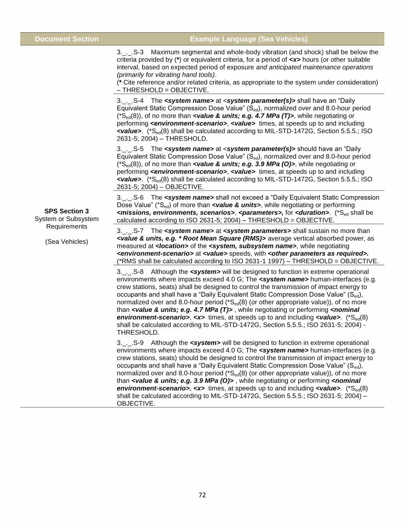
72
Document Section Example Language (Sea Vehicles)
SPS Section 3 System or Subsystem
Requirements
(Sea Vehicles)
3._._.S-3 Maximum segmental and whole-body vibration (and shock) shall be below the criteria provided by (*) or equivalent criteria, for a period of <x> hours (or other suitable interval, based on expected period of exposure and anticipated maintenance operations (primarily for vibrating hand tools). (* Cite reference and/or related criteria, as appropriate to the system under consideration) – THRESHOLD = OBJECTIVE.
3._._.S-4 The <system name> at <system parameter(s)> shall have an “Daily Equivalent Static Compression Dose Value” (Sed), normalized over and 8.0-hour period (*Sed(8)), of no more than <value & units; e.g. 4.7 MPa (T)>, while negotiating or performing <environment-scenario>, <value> times, at speeds up to and including <value>. (*Sed(8) shall be calculated according to MIL-STD-1472G, Section 5.5.5.; ISO 2631-5; 2004) – THRESHOLD.
3._._.S-5 The <system name> at <system parameter(s)> should have an “Daily Equivalent Static Compression Dose Value” (Sed), normalized over and 8.0-hour period (*Sed(8)), of no more than <value & units; e.g. 3.9 MPa (O)>, while negotiating or performing <environment-scenario>, <value> times, at speeds up to and including <value>. (*Sed(8) shall be calculated according to MIL-STD-1472G, Section 5.5.5.; ISO 2631-5; 2004) – OBJECTIVE.
3._._.S-6 The <system name> shall not exceed a “Daily Equivalent Static Compression Dose Value” (*Sed) of more than <value & units>, while negotiating or performing <missions, environments, scenarios>, <parameters>, for <duration>. (*Sed shall be calculated according to ISO 2631-5; 2004) – THRESHOLD = OBJECTIVE.
3._._.S-7 The <system name> at <system parameters> shall sustain no more than <value & units, e.g. * Root Mean Square (RMS)> average vertical absorbed power, as measured at <location> of the <system, subsystem name>, while negotiating <environment-scenario> at <value> speeds, with <other parameters as required>. (*RMS shall be calculated according to ISO 2631-1 1997) – THRESHOLD = OBJECTIVE.
3._._.S-8 Although the <system> will be designed to function in extreme operational environments where impacts exceed 4.0 G; The <system name> human-interfaces (e.g. crew stations, seats) shall be designed to control the transmission of impact energy to occupants and shall have a “Daily Equivalent Static Compression Dose Value” (Sed), normalized over and 8.0-hour period (*Sed(8) (or other appropriate value)), of no more than <value & units; e.g. 4.7 MPa (T)> , while negotiating or performing <nominal environment-scenario>, <x> times, at speeds up to and including <value>. (*Sed(8) shall be calculated according to MIL-STD-1472G, Section 5.5.5.; ISO 2631-5; 2004) - THRESHOLD.
3._._.S-9 Although the <system> will be designed to function in extreme operational environments where impacts exceed 4.0 G; The <system name> human-interfaces (e.g. crew stations, seats) should be designed to control the transmission of impact energy to occupants and shall have a “Daily Equivalent Static Compression Dose Value” (Sed), normalized over and 8.0-hour period (*Sed(8) (or other appropriate value)), of no more than <value & units; e.g. 3.9 MPa (O)> , while negotiating or performing <nominal environment-scenario>, <x> times, at speeds up to and including <value>. (*Sed(8) shall be calculated according to MIL-STD-1472G, Section 5.5.5.; ISO 2631-5; 2004) – OBJECTIVE.

73
Document Section Example Language (Sea Vehicles)
SPS Section 3 System or Subsystem
Requirements
(Sea Vehicles)
3._._.S-10 The <system name> at <parameter> and <system parameter> shall sustain no more than <value & units (T)> vertical acceleration, as measured at each crew seat base location while negotiating <environment, obstacles>, at the rated speed of <values>. (Vertical acceleration (peak) shall be calculated according to ISO 2631-1 1997) – THRESHOLD
3._._.S-11 The <system name> at <parameter> and <system parameter> should sustain no more than <value & units (O)> vertical acceleration, as measured at each crew seat base location while negotiating <environment, obstacles>, at the rated speed of <values>. (Vertical acceleration (peak) shall be calculated according to ISO 2631-1 1997) – OBJECTIVE
3._._.S-12 The <system name> at < system parameters> shall have a Vibration Dose Value (VDV) of no more than <value & units> cumulative, while negotiating <environment, obstacles>, <x> times, <duration> at speeds up to and including <value>. (*VDV shall be calculated according to ISO 2631-1 1997) – THRESHOLD = OBJECTIVE
Document Section Example Language (General)
SPS Section 3
System or Subsystem Requirements
(General)
3._._.G-1 The <vehicle, system name> seating systems shall be designed to minimize the transmission of vehicle vibration and shock to the occupant(s) IAW MIL-STD-1472 – THRESHOLD = OBJECTIVE.
3._._.G-2 The crew and passengers/troops shall not be exposed to vibrations which reduce their effectiveness or increase their workload while performing their required missions as specified in MIL-STD-1472G, section 5.5.5, ISO 2631-1) - THRESHOLD = OBJECTIVE.
3._._.G-3 The crew and passengers/troops shall not be exposed to individual or repeated jarring impacts which reduce their effectiveness or increase their workload while performing their required missions in accordance with MIL-STD-1472G, section 5.5.5., ISO 2631-5) - THRESHOLD = OBJECTIVE.
3._._.G-4 The <system name> shall address applicable Human Systems Integration (HSI) domains (Manpower, Personnel, Training, Human Factors Engineering (HFE), Environment-Safety-Occupational Health (ESOH), Personnel Survivability, and Habitability) to optimize total system performance, minimize total operational cost, and ensure the system is built to accommodate the characteristics of the user population in relation to whole-body vibration reduction/prevention that will operate, maintain, and support the system – THRESHOLD.
3._._.G-4b The <system name> should address applicable Human Systems Integration (HSI) domains (Manpower, Personnel, Training, Human Factors Engineering (HFE), Environment-Safety-Occupational Health (ESOH), Personnel Survivability, and Habitability) to optimize total system performance, minimize total operational cost, and ensure the system is built to accommodate the characteristics of the user population in relation to whole-body vibration reduction/prevention that will operate, maintain, and support the system – OBJECTIVE.

74
Document Section Example Language (General)
SPS Section 3 System or Subsystem
Requirements
(General)
3._._.G-5 The system shall be designed to eliminate or mitigate safety, health or physical risks. Where hazards/risks exist, health and safety equipment and/or procedures must be identified. Health and Safety procedures and engineering design considerations must conform to all pertinent standards. Crew task load, fatigue factors, broad range of operation environments, and data assimilation must be considered - THRESHOLD = OBJECTIVE.
3._._.G-6 The <system> environment, safety and health risks shall be eliminated, minimized or controlled to acceptable levels using improbable risk levels, as defined in MIL-STD-882 and equivalent commercial standards during aircraft system life - THRESHOLD = OBJECTIVE.
3._._.G-7 The <system> shall have acceptable ESOH risk levels of all potentials for mishaps IAW MIL-STD-882, Tables A-II, A-III, and A-IV - THRESHOLD = OBJECTIVE.
3._._.G-8 For the <system>, safety considerations shall be provided for in the program baseline to support sustainable operation and maintenance. The program shall maintain a <system> safety process to identify and prevent ESOH hazards where possible, and shall manage ESOH hazards where they cannot be avoided IAW MIL-STD-882E - THRESHOLD = OBJECTIVE.
3._._.G-9 System designs shall minimize or eliminate system characteristics that require extensive training or workload-intensive tasks; result in mission-critical errors; or produce safety or health hazards. Designs will be consistent with human factors engineering criteria per references < MIL-STD-1472G, MIL-STD-46855A, MIL-STD-882E, insert related criteria as appropriate to the system under consideration> - THRESHOLD = OBJECTIVE.
3._._.G-10 Human factors engineering principles and design standards shall be applied to the design of the system. Designs shall be consistent with human factors engineering references <MIL-STD-46855A, MIL-STD-882E, MIL-STD-1472G, insert related criteria, as appropriate to the system under consideration> - THRESHOLD = OBJECTIVE.
3._._.G-11 All human engineering aspects shall be in compliance with current Human Factors Engineering (HFE) practices and be coordinated by a Human Factors Engineer - THRESHOLD = OBJECTIVE.
Document Section Section Notes / Guidance
SPS Section 4 Verification
Verification is a fundamental process used to demonstrate that the system design meets applicable requirements and is capable of sustaining its operational role during the life cycle.
Verification uses established criteria to conduct early verification of the physical architecture (including software and interfaces) from the lowest level up to the total system to ensure that cost, schedule, and all functional, performance, and design requirements are satisfied with acceptable levels of risk.
Document Section Section Notes / Guidance
SPS Section 4 Verification
(Verification Cross
Reference Matrix (VCRM)
A method to verify each requirement and a corresponding set of verification objectives (VO) are established and recorded during requirements analysis and functional allocation activities. The resulting verification cross reference matrix (VCRM) and verification objective data attributes have direct relationships to the specifications and will be updated, as required, to correspond to the approved capability objectives and requirements.
An example VCRM is provided below (Table 25) which contains WBV and/or repetitive impact exposure reduction language generally formatted in line with SPS/SRD development guidance. See table 25 at the end of the SPS/SRD section

75
Document Section Section Notes / Guidance
SPS Section 4 Verification Provisions
(Methodology)
Ensure Section 4 Verification Provisions, methodology documents how each requirement (attribute) <whole-body vibration and/or repetitive impact> is to be verified.
The Government team members developing Section 3 Requirements should put thought into conceptual verification method(s) when developing the requirement and verification provisions. If the verification methods/provisions associated with a requirement in Section 3 are either unclear, or difficult to explain or discern, it is a good indication the Section 3 Requirement itself is poorly written and should be re-worked.
Document Section Example Language
SPS Section 4 Verification Provisions
(Methodology)
Verification methodologies for WBV and/or repetitive impact exposure requirements shall utilize the best practices methodologies as specified in MIL-STD 1472G, and the ISO 2631-1 and ISO 2631-5 standards referenced therein.
Verification methodologies for WBV and/or repetitive impact exposure requirements shall derived from the guidelines outlined in MIL-STD-1472G, and the ISO 2631-1 and ISO 2631-5 standards referenced therein.
The following provision apply to whole-body vibration, where the vibratory motions are limited to those transmitted to the human body as a whole through supporting surfaces (IAW ISO 2041 and ISO 5805). This includes the feet for the standing occupant, the buttocks, back, and feet for the seated occupant, and the supporting surface of the occupant lying on his or her back. The applicable frequency range is defined as:
a. 0.1 to 0.5 or <value> Hertz for motion sickness
b. 0.5 to 80 or <value> Hertz for health, performance, comfort, and perception
(MIL-STD-1472G, Section 5.5.5.1 Vehicular whole-body vibration)
SPS Section 4 Verification Provisions
(General Methodology
Examples)
3._._.A-1 through A-12
Verify that, for rotary wing air vehicles, the effects of high-energy, low-frequency vibrations, generated by main rotor blade passage (fundamental and harmonic) frequencies at all engine and related component operating speeds and powers, do not adversely affect the operation of the engine and the drive system.
Verify, for rotary wing air vehicles, that a satisfactory interface is achieved between the engine (including subsystems/accessories) and the airframe relative to both high-frequency engine-excited and low-frequency air vehicle rotor(s) excited vibrations.
Verify that the propulsion system is free of destructive vibrations at all steady state and transient operating conditions and is capable of balancing to remove vibration that could cause equipment to operate below specified requirements or cause excessive crew discomfort and/or performance degradation.
SPS Section 4 Verification Provisions
(General Methodology
Examples)
3._._.A-6 Simultaneous measurements of the ride quality instrumentation, the track and balance
accelerometers, and any other vibration instrumentation used shall be made at 4 steady state flight conditions including <x> and two other conditions which are critical for vibration. Data from the selected points should be capable of determining if the installed vibration control devices are functioning correctly.
The first 10 production <system> shall be instrumented with a ride quality instrumentation package comprehensive enough to verify compliance with the detailed specification. During the following procedures, the <system> shall be flown in such a manner as to verify compliance with the detailed specification.
Acceptance level is designed to assure, with <x; e.g. 99%> probability, that if vibration measurements on an aircraft (at the corresponding locations and conditions) fall below <x level> then that <system> would also meet the detail specification vibration requirements.
It shall be determined which vibration pickup locations show the best correlation with the ride quality measurements and these shall be established as the monitoring pickup locations for future production <systems>.

76
Document Section Example Language
SPS Section 4 Verification Provisions
(General Methodology
Examples)
3._._.A-10
For verification, triaxial acceleration data shall be processed in accordance with MIL-STD-1472G, Section 5.5.5.; ISO 2631-1; 1997, using the basic evaluation method and the frequency weightings and multiplying factors for health.
3._._.L-4
Verify <system name> can maneuver as part of the armored <Z> and must be capable of traversing the same terrain as the <XX; legacy>. The threshold values represent demonstrated performance of the <YY system>. The objective values correspond to the <XX> with <n upgrade>. Achieving this performance will allow the <system name> to maneuver with the rest of the <Z>. <x> Watts absorbed power is the vehicle standard that ensures occupants are combat effective after dismounting the vehicle.
Verification: Incremental Test (in accordance with applicable standards), RMS Course X
3._._.A-2 3._._.L-5 Passenger stations accommodation/generic design verification. Comfort - Verify seat comfort requirements for promoting good posture, body support, preventing “hot spots” and, isolating vibration shall be incrementally verified (through demonstration with representative personnel).
3._._.G-2 System Vibration Mitigation – Crew/Passenger Effectiveness
Human performance shall be demonstrated and measured through Human Systems Integration (HSI) simulation and testing using representative operator and maintainer personnel and representative operational scenarios.
3._._.G-9 through G-11 The test article will be evaluated for adherence to optimum human factors referenced
in MIL-STD-1472. The assessment will include visual inspection for quality of workmanship.
Activities shall identify ergonomic risk factors as part of, or in conjunction with analysis, functional tests or demonstrations required. Risk factors to consider include awkward and static posture, excessive force or repetition, contact stress, segmental or whole-body vibration or impact forces (shock), and high hand forces.
SPS Section 4 Verification Provisions
(General Methodology
Examples)
Evaluation of <system, vehicle> vibration and its possible effects on health, performance, comfort, perception, and motion sickness shall be in accordance with ISO 2631 and associated amendments (ref MIL-STD-1472G, Section 5.5.5.1.2 b.) The basic evaluation method shall be applied for all environment categories listed in table <Z>
Table <Z>
Category Description of Environment
A. The environment is classified as strictly vibration and can be characterized as oscillatory in nature (periodic)
B. The environment is classified as predominantly vibration and can be characterized as oscillatory in nature (periodic) but also contains occasional shocks or transient vibration (aperiodic)
C. The environment may contain some underlying vibration, but is dominated by repeated or multiple shocks or transient vibration
Category A: vibration. Tri-axial acceleration data shall be processed in accordance with
ISO 2631-1;1997 (See MIL-STD-1472G, Section 5.5.5.1.3 a)
Category B: vibration with occasional shock or transient vibration. Tri-axial acceleration data shall be processed in accordance with ISO 2631-1;1997 (See MIL-STD-1472G, Section 5.5.5.1.3 b)
Category C: repeated/multiple impacts (shocks) or transient vibration. The primary evaluation methodology and limits for this environment shall be in accordance with ISO 2631-5 (See MIL-STD-1472G, Section 5.5.5.1.3 c)

77
Document Section Example Language
SPS Section 4 Verification Provisions
(General Methodology Examples)
Once a seat has been designed to provide proper support for the human body, the human factors specialist must then decide where to locate the seat in relation to the rest of the system. For vehicular seating in airplanes, the seat is one component of a three-dimensional workspace. Vehicle drivers must be able to have proper lines of sight and to reach all controls in the vehicle cabin/cab.
Seating Verifications (not all inclusive) The main weight of the body should be carried by the bony protuberances of the
buttocks, more technically known as the ischial tuberosities. The thighs should exert as little pressure as possible on the seat or on the front edge
of the seat The lumbar (lower) portion of the back must be supported The feet must be able to be placed firmly on the floor, or if this is not possible, on a
footrest The seated person should be able to change posture (without getting up)
Verify that the seat provides for the safety and protection of occupants from mission threats, hazards of operation, crashing, and emergency egress shall be incrementally verified.
Verify that the airframe is designed such that it can operate in the vibration environments induced by the operational use for the specified service life. Also verify that the airframe is designed such that no fatigue cracking or excessive vibration of the airframe structure or components occurs that would result in the air vehicle, the components of the air vehicle systems, or the operator(s) of the air vehicle not being fully functional.
Verify that all controls and displays are arranged and located so that they are completely functional and visible and that cockpit or operator station geometry (including seats) accommodates the specified multivariate mission crew population.
Verify that all functional operations can be safely performed including tasks performed by crew, operators, and maintainers.
Verify that all operating instructions, handbooks/checklists, performance management and planning systems, and other relevant documentation, are not in conflict with system descriptions and procedures (normal and emergency) and actual system performance; that emergency procedures are clear and corrective actions don not create other hazardous situations; and that all procedures or vehicle interfaces can be accomplished within acceptable workload limits.
Verify that the crew system interface is designed to reduce the potential for, and minimize the consequences of, a crew-induced error, and provides a simple means to correct an error (MIL-STD-1472).
Verify that seating system load capabilities are commensurate with the vehicle type for crew and passengers and that the design of the floor and load paths to the seat attachments <with upgraded/installed vibration isolation-damping capabilities> are capable of sustaining the loads of the seat system in applicable crash or other load conditions.
Verify the stroke clearance envelope for energy absorbing seats (clear of structures and equipment which could impede seat stroke).
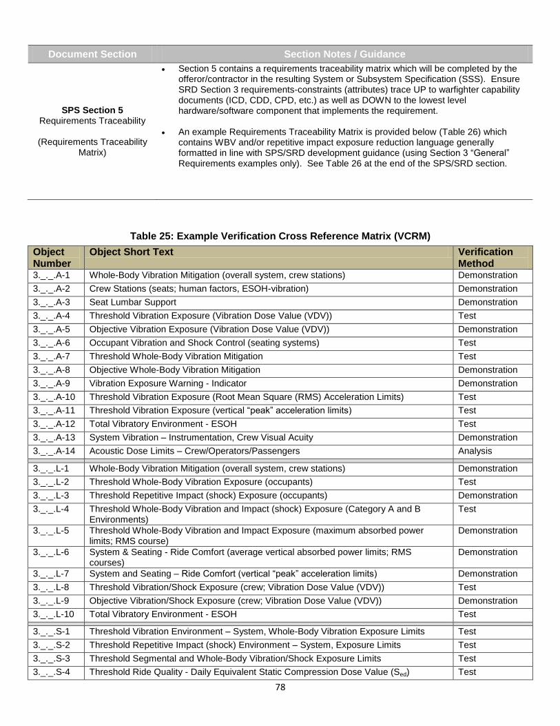
78
Document Section Section Notes / Guidance
SPS Section 5 Requirements Traceability
(Requirements Traceability
Matrix)
Section 5 contains a requirements traceability matrix which will be completed by the offeror/contractor in the resulting System or Subsystem Specification (SSS). Ensure SRD Section 3 requirements-constraints (attributes) trace UP to warfighter capability documents (ICD, CDD, CPD, etc.) as well as DOWN to the lowest level hardware/software component that implements the requirement.
An example Requirements Traceability Matrix is provided below (Table 26) which contains WBV and/or repetitive impact exposure reduction language generally formatted in line with SPS/SRD development guidance (using Section 3 “General” Requirements examples only). See Table 26 at the end of the SPS/SRD section.
Table 25: Example Verification Cross Reference Matrix (VCRM)
Object Number
Object Short Text Verification Method
3._._.A-1 Whole-Body Vibration Mitigation (overall system, crew stations) Demonstration
3._._.A-2 Crew Stations (seats; human factors, ESOH-vibration) Demonstration
3._._.A-3 Seat Lumbar Support Demonstration
3._._.A-4 Threshold Vibration Exposure (Vibration Dose Value (VDV)) Test
3._._.A-5 Objective Vibration Exposure (Vibration Dose Value (VDV)) Demonstration
3._._.A-6 Occupant Vibration and Shock Control (seating systems) Test
3._._.A-7 Threshold Whole-Body Vibration Mitigation Test
3._._.A-8 Objective Whole-Body Vibration Mitigation Demonstration
3._._.A-9 Vibration Exposure Warning - Indicator Demonstration
3._._.A-10 Threshold Vibration Exposure (Root Mean Square (RMS) Acceleration Limits) Test
3._._.A-11 Threshold Vibration Exposure (vertical “peak” acceleration limits) Test
3._._.A-12 Total Vibratory Environment - ESOH Test
3._._.A-13 System Vibration – Instrumentation, Crew Visual Acuity Demonstration
3._._.A-14 Acoustic Dose Limits – Crew/Operators/Passengers Analysis
3._._.L-1 Whole-Body Vibration Mitigation (overall system, crew stations) Demonstration
3._._.L-2 Threshold Whole-Body Vibration Exposure (occupants) Test
3._._.L-3 Threshold Repetitive Impact (shock) Exposure (occupants) Demonstration
3._._.L-4 Threshold Whole-Body Vibration and Impact (shock) Exposure (Category A and B Environments)
Test
3._._.L-5 Threshold Whole-Body Vibration and Impact Exposure (maximum absorbed power limits; RMS course)
Demonstration
3._._.L-6 System & Seating - Ride Comfort (average vertical absorbed power limits; RMS courses)
Demonstration
3._._.L-7 System and Seating – Ride Comfort (vertical “peak” acceleration limits) Demonstration
3._._.L-8 Threshold Vibration/Shock Exposure (crew; Vibration Dose Value (VDV)) Test
3._._.L-9 Objective Vibration/Shock Exposure (crew; Vibration Dose Value (VDV)) Demonstration
3._._.L-10 Total Vibratory Environment - ESOH Test
3._._.S-1 Threshold Vibration Environment – System, Whole-Body Vibration Exposure Limits Test
3._._.S-2 Threshold Repetitive Impact (shock) Environment – System, Exposure Limits Test
3._._.S-3 Threshold Segmental and Whole-Body Vibration/Shock Exposure Limits Test
3._._.S-4 Threshold Ride Quality - Daily Equivalent Static Compression Dose Value (Sed) Test

79
Object Number
Object Short Text Verification Method
3._._.S-5 Objective Ride Quality - Daily Equivalent Static Compression Dose Value (Sed) Test
3._._.S-6 Threshold Ride Quality (Not to Exceed) - Daily Equivalent Static Compression Dose Value (Sed)
Test
3._._.S-7 Threshold Ride Quality (Occupant Exposure; Root Mean Square (RMS) average vertical absorbed power)
Demonstration
3._._.S-8 Threshold Ride Quality - Daily Equivalent Static Compression Dose Value (Sed) Test
3._._.S-9 Objective Ride Quality - Daily Equivalent Static Compression Dose Value (Sed) Demonstration
3._._.S-10 Threshold Vibration/Shock Exposure (vertical “peak” acceleration) Test
3._._.S-11 Objective Vibration/Shock Exposure (vertical “peak” acceleration) Demonstration
3._._.S-12 Threshold Vibration Daily Dose (VDV) Exposure Test
3._._.G-1 ESOH Risk Reduction – Seating Systems Demonstration
3._._.G-2 System Vibration Mitigation – Crew/Passenger Effectiveness Demonstration
3._._.G-3 Repetitive Impact/Shock Mitigation – Crew/Passenger Effectiveness Demonstration
3._._.G-4 Human Systems Integration (HSI) Practices Demonstration
3._._.G-4b Human Systems Integration (HSI) Practices Analysis
3._._.G-5 ESOH Risk Reduction Analysis
3._._.G-6 ESOH Risk Management Demonstration
3._._.G-7 ESOH Risk Reduction Analysis
3._._.G-8 ESOH Hazards Management/Reduction Demonstration
3._._.G-9 ESOH, Human Factors Engineering (HFE) Risk Reduction – System Design Demonstration
3._._.G-10 HFE Criteria – ESOH Risk Reduction Analysis
3._._.G-11 Human Factors Engineering Demonstration
Table 26: Example Requirements Traceability Matrix
Requirement Number <System> SRD Requirement Short Text
<System> CDD (Version __) Requirement Link
3._._.G-1 ESOH Risk Reduction – Seating Systems 6.x.x.G-x (ICD, CDD, CPD
identifier)
3._._.G-2 System Vibration Mitigation – Crew/Passenger Effectiveness 6.x.x.G-x
3._._.G-3 Repetitive Impact/Shock Mitigation – Crew/Passenger Effectiveness 6.x.x.G-x
3._._.G-4 Human Systems Integration (HSI) Practices 6.x.x.G-x
3._._.G-4b Human Systems Integration (HSI) Practices 6.x.x.G-x
3._._.G-5 ESOH Risk Reduction 6.x.x.G-x
3._._.G-6 ESOH Risk Management 6.x.x.G-x
3._._.G-7 ESOH Risk Reduction 6.x.x.G-x
3._._.G-8 ESOH Hazards Management/Reduction 6.x.x.G-x
3._._.G-9 ESOH, Human Factors Engineering (HFE) Risk Reduction – System Design
6.x.x.G-x
3._._.G-10 HFE Criteria – ESOH Risk Reduction 6.x.x.G-x
3._._.G-11 Human Factors Engineering 6.x.x.G-x

80
Request for Proposal (RFP)
The suggestions, example language provided, and the placement of the language within the document(s) are presented as a reference for acquisition and other professionals. Examples are not necessarily meant to be specific for any particular type of system or acquisition program. Suggestions and examples provided are intended to assist acquisition professionals by providing a starting point for tailoring language unique to
individual development programs. Specific standards can be obtained from an HSI practitioner or from any of the sources identified in the Standards and/or References tab. A Request for Proposal (RFP) is a solicitation used in negotiated acquisition to communicate government requirements to prospective contractor and to solicit proposals. At a minimum, solicitations shall describe the Government’s requirements, anticipated terms and conditions that will apply to the contract, information required in the offeror’s proposal, and (for competitive acquisitions) the criteria that will be used to evaluate the proposal and their relative importance. FAR Subpart 15.2 "Solicitation and Receipt of Proposals and Information" is the main guidance for government solicitations and RFPs.
RFP Model Language for Whole-Body Vibration (WBV) and/or Repetitive Impact This section provides model language (examples / statements) to address WBV and/or repetitive impact. Information in the form of Section Notes or Guidance may be provided which is generally applicable to the RFP Section identified. These sections may include Example Tables or other information (with WBV / Impact examples), presented in an RFP-representative format. The examples and formats provided will vary, in order to present the user with broad options and a general starting point for a RFP intended to incorporate WBV and/or repetitive impact as an important attribute(s). The user of this Guide is reminded that the information provided is intended to assist in “crafting” or “tailoring” language most appropriate to their particular program or set of circumstances, not to be a direct “cut-and-paste” solution.
- KEY -
<…> “Insert Applicable Information Here” (i.e. <x>, <X>, <Y>, <Z>, etc.)
<name, value, other>… Same as Above with category or example of information needed
6._._.G-x Placeholder: example “unique identifier” for example language
“SPS” and “SRD” System Performance Specification (SPS) and System Requirements Document (SRD); are/may be used interchangeably in this Section (and other sections of this QRG)
References to “HSI” “ESOH” WBV and/or repetitive impact exposure (mitigation/reduction) is an “implied” consideration
Table 27: RFP Section
Document RFP Notes / Guidance
Request For Proposal (RFP)
(General)
System requirements which are specific to whole-body vibration and/or repetitive impact, and that require special emphasis (i.e. have testable KPP, KSA, Additional or Other System Attributes (Threshold/Objective)), should be included in <system> SPS/SRD, and provided with the RFP as part of Section C.
HSI considerations not specifically called out in the SPS/SRD, and/or CDD, (those “linked” to other performance requirements but without their own KPP, KSA, Additional or Other System Attributes (Threshold/Objective values), etc.), should be delineated as contract requirements and addressed within the RFP where appropriate (i.e. Statement of Objectives (SOO), Performance Work Statement (PWS), Statement of Work (SOW), and/or other RFP Sections as necessary). See SURVIAC. (2009). Human Systems Integration for Contracts: Integration of HSI Language into Acquisition Contracts. Brooks City-Base, TX: 711
th HPW/HPO for additional guidance.
Request for Proposal (RFP) Home

81
Document Section Section Notes / Guidance
RFP
Statement of Objectives (SOO)
The SOO expresses in terms of minimal needs and encourages the offeror to suggest the most cost-effective system. The SOO is a statement of the government’s most important desired outcomes. In most cases, a document defining system-level and key subsystem performance requirements accompanies the RFP/SOO (i.e. the System Performance Specification (SPS) or System Requirements Document (SRD))
- This approach provides potential offerors the flexibility to develop cost-effective solutions and to propose innovative alternatives.
Document Section Example Language
RFP
SOO
(General)
The program’s technical approach will capitalize on Government and industry standards, policies, and directives while leveraging the contractor’s Human Systems Integration HSI domain experience and “enterprise processes.” The technical objectives for the program (as related to controlling crewmember/operator(s) exposure to whole-body vibration and/or repetitive impact) are (Including but not limited to):
Design, develop, test, and deliver a system which meets the performance requirements of the user, while meeting the system attribute <threshold / objective> for crew systems (see SPS/SRD for specific system and subsystem requirements).
Use contractor’s “enterprise processes” to execute the program. Flow down policies and processes to the lowest level of contractor’s team (subcontractors, teammates, or vendors). Employ continuous process improvement activities, integrating both Government and contractor practices as processes. Ensure Government technical HSI processes, as defined in the SEP (or HSIP), are integrated and consistent with the contractor’s technical processes.
Ensure synergy between government SEP and contractor systems engineering planning and processes (i.e. contractor SEMP or other SE planning document(s)).
Include all HSI considerations (existing or derived) in planned event-based technical reviews included in the IMP and IMS with specific entry and exit criteria.
RFP
SOO
(HSI Language)
Human-in-the-loop considerations are critically important to the design and development effort of <system> are (Including but not limited to):
The contractor must employ a sound Human Systems Integration (HSI) approach, embedded with systems engineering to ensure effective, safe, low hazard operation, minimize total operation cost and ensure the system is built to address the capabilities of the users that will operate, maintain, and support the system.
Establish and implement systems engineering practices that ensure HSI domain objectives are addressed and integrated during all phases of the program.
Establish or support an HSI Working Group (HSIWG), or other appropriate mechanism to ensure HSI issues with the development of <system> are identified and addressed (See SRD (KSAs) for crew station <WBV, Repetitive Impact Threshold/Objective> requirements). The HSIWG will communicate and track resolution of HSI discrepancies with the rest of the program stakeholders (PM, software/hardware engineering, etc.).
Develop, implement and maintain a full HSI Program Plan (HSIPP) which documents objectives and demonstrates a sound program approach and an understanding of criticality of HSI considerations as they relate to <system> requirements (See SRD; e.g. KSA for <WBV, Repetitive Impact Threshold/Objective>). Specific activities that will be accomplished, either as the responsibility of HSI or in support of other disciplines <e.g. WBV, Repetitive Impact mitigation efforts>, shall be listed in the Integrated Master Schedule and tracked to completion for Earned Value Management, with results presented at defined milestone events and captured in
appropriate document/data deliverables.

82
Document Section Example Language
RFP
SOO
(HFE Language)
Human Factors Engineering design efforts shall focus on minimizing or eliminating system characteristics that result in mission-critical errors or produce safety or health hazards due to (Including but not limited to):
Whole-Body Vibration exposure; <system>-producing and/or operating environment-induced vibration; transferred to crew or occupants (see SRD <KSA, other Thresholds, Objectives, etc.>).
Repetitive impact loads/energy (shock) exposure; <system>-producing and/or operating environment-induced impact energy (shock); transferred to crew or occupants (see SRD #___; <KSA, other Thresholds, Objectives, etc.>).
RFP
SOO
(ESOH Language)
Develop, implement, and maintain a System Safety Program plan (SSPP) <or other reference> which documents and implements safety critical function processes. The SSPP shall address civil and military processes (AC 25.1309-1A, MIL-STD-882D, etc.) for hardware system safety analysis, human factors and system safety program management.
Develop and maintain a list of critical safety items.
Support the <system name> System Safety Group and System Safety Working Group (SSWG).
Identify and develop plans to address the hazards of whole-body vibration in accordance with MIL-STD-1472 (See SRD #____; <KSA, or other for WBV, Repetitive Impact Threshold/Objective>).
Identify and develop plans to address the hazards of repetitive impact (multiple shock) in accordance with MIL-STD-1472 (See SRD #____; <KSA, or other for Repetitive Impact Threshold/Objective>).
Establish an unrestricted hazard data tracking system that will be easily accessible by testers, operators and maintainers, and will be transferable to the sustainer when the system is fielded.
Identified safety, and health risks caused by system vibration shall be eliminated, minimized or controlled to acceptable levels within cost, schedule, and performance constraints. All health risks associated with operation, maintenance and support shall be identified during development and design, and shall be eliminated or mitigated to an acceptable level as agreed by a government HSI team (Including but not limited to):.
Whole-Body Vibration exposure; <system>-producing and/or operating environment-induced vibration; transferred to crew or occupants (see SRD <KSA, other Thresholds, Objectives, etc.>).
Repetitive impact loads/energy (shock) exposure; <system>-producing and/or operating environment-induced impact energy (shock); transferred to crew or occupants (see SRD <KSA, other Thresholds, Objectives, etc.>).
ESOH Risks - Identified safety, and occupational health risks caused by excessive exposure to whole-body vibration or repetitive impact energy (shock) shall be eliminated, minimized or controlled to acceptable levels within cost, schedule, and performance constraints. All health risks associated (system operation, maintenance and support) with system vibration or repetitive impact energy (shock loads) shall be identified during development and design, and shall be eliminated or mitigated to meet requirements (See SRD; <KSA, other Thresholds, Objectives, MIL-STD-1472G, Section 5.5.5.>).

83
Document Section Example Language
RFP
SOO
(ESOH Language)
Program ESOH Protection Goal - The fielded system shall 1) be compliant with applicable ESOH laws and regulations concerning whole-body vibration and repetitive impacts, 2) minimize safety and occupational health hazards (must include human exposure to vibration or repetitive impacts, 3) reduce/prevent vibration at the source, 4) minimize ESOH impacts to program cost, schedule and performance through the system life cycle, 5) generate a lesser* mishap rate, and 6) produce/transfer lower* human exposure amounts of vibration or repetitive impacts than its equivalent systems without adverse impact to cost, performance or schedule.*
(* The terms “lower”, “fewer” and “lesser” should be replaced with quantitative objectives, specifically developed for the system. Also the types of mishaps to be reduced should be qualified – See SRD)
ESOH Hazard Goal - Identify and eliminate, reduce or control ESOH hazards and the associated risks within the constraints of program cost, schedule and performance throughout the life cycle of the system (Including but not limited to):
Whole-Body Vibration exposure; <system>-producing and/or operating environment-induced vibration; transferred to crew or occupants (see SRD <KSA, other Thresholds, Objectives, etc.>).
Repetitive impact loads/energy (shock) exposure; <system>-producing and/or operating environment-induced impact energy (shock); transferred to crew or occupants (see SRD <KSA, other Thresholds, Objectives, etc.>).
Document Section Section Notes / Guidance
RFP
PWS/SOW
The Performance Work Statement (PWS) is one of three optional work statement methods (SOO, PWS, SOW); focuses on what the contractor is to perform, rather than how to do the work.
The SOW describes the contract tasks that must be performed and the conditions under which they are to be performed. Either the contractor or the government may generate the SOW, but both parties must agree to it. The SOW can be generated by the contractor in the proposal responding to the RFP. SOWs must be performance or outcome oriented without detailed procedures.
Specific HSI considerations requiring emphasis, (such as WBV or repetitive impact exposure system attributes/requirements) should be stated in the performance specifications (SPS/SRD) and provided as part of the RFP in Section C.
Generally, a SOW statement or paragraph will provide a reference to an associated CDRL. In the CDRL, reference is made to a Data Item Description (DID) which provide detailed guidance on the format, content, and preparation for data items (e.g. DI-HFAC-81743 for HSIPP).

84
Document Section Example Language
RFP
PWS/SOW
The offeror shall provide a PWS/SOW to be included in the negotiated contract that specifically identifies HSI efforts. The PWS/SOW shall:
Describe the technical work, tasks, and activities to be accomplished on the <system name, program> that reflect the HSI planning to the program as described in the offeror’s systems engineering plan.
Address the technical baseline management process (functional, allocated, and product baselines) to include HSI practices.
Include HSI considerations in all planned event-based technical reviews with entry and exit criteria. All technical reviews shall include (as necessary and appropriate) address issues or progress towards meeting whole-body vibration exposure and/or repetitive impact exposure requirements (see SRD #____ <KSA, other Thresholds, Objectives, etc.>).
The government’s goal is to maximize human performance at the lowest total ownership cost by integrating HSI considerations (goals, requirements, constraints, risk) into the SE process while minimizing the impact to program cost and schedule performance. The contractor shall:
Establish HSI sub-objectives and performance criteria as the first step in meeting HSI goals <and/or requirements, KPP, KSAs, Other System Attributes, etc.>. The best commercial practices shall be used in developing and documenting these sub-objectives.
Fully integrate HSI into the SE processes and planning documents (i.e. combined SEP or contractor SEMP).
Integrate HSI aspects, <WBV and impact requirements with KPPs, KSAs, Other System Attributes.>, into all documents, studies, and plans required by the system design, development, testing, and production processes.
RFP
PWS/SOW
(General – HSI/HFE)
The contractor shall apply effective HSI principles and design activities during <system> <design, production and integration, etc.>. The contractor shall develop and execute an HSI program/effort that ensures <HSI domains> aspects and requirements have been incorporated into the layout, design, and development of equipment affecting operators or having an operator and/or maintainer interface. The contractor shall:
Define human and human-system tasks with performance, decision, and information requirements as it relates to reducing occupant exposure to WBV and/or repetitive impact requirements; see SPS/SRD, RFP Section C>.
Identify human-machine interfaces that support task performance; physical and cognitive workloads <including WBV and repetitive impact requirements; or see SPS/SRD, RFP Section C>.
Conduct analysis to determine manpower and tasking required to operate, maintain, and support the system over the life cycle, based on all performance requirements <including WBV and repetitive impact requirements; or see SPS/SRD, RFP Section C>.
Conduct evaluation activities that include requirements for human performance, workload, survivability, and safety <including WBV and repetitive impact requirements; or see SPS/SRD, RFP Section C>. The contractor shall conduct requirement and functional analysis that will detail requirements for human-machine interfaces, personnel skills and knowledge, and instructional systems development and training delivery <including WBV and repetitive impact requirements; see SPS/SRD, RFP Section C>.

85
Document Section Example Language
RFP
PWS/SOW
(General – HFE)
The contractor shall describe the equipment which interfaces with operators, providing a source of data to evaluate the extent to which equipment having an interface with operators meets human performance requirements and human factors engineering criteria. The contractor shall describe the extent to which human performance requirements and applicable human factors engineering design criteria (MIL-STD-1472) have been incorporated into the layout, design, and arrangement of equipment having an operator interface. The contractor shall describe the operator(s) interfaces with specific emphasis on the design to mitigate or reduce occupant exposure to WBV and repetitive impacts as related to <SPS or SRD requirement # ____> (See System Performance Specification, Crew Station Requirements, provided within Section C of the RFP).
Apply CDRL <reference number>
RFP
PWS/SOW
(General – TEMP, Value Engineering, HSIPP)
The offeror shall demonstrate adherence, or commitment to the Government’s Test and Evaluation Master Plan (TEMP) which captures how the test and evaluation (T&E) process will operate for the program.
The offeror’s systems engineering process shall demonstrate knowledge and familiarity with Value Engineering (VE) principles <as appropriate, VE incentives applied to WBV and/or repetitive impact mitigation/reduction compared to existing or legacy systems>.
The contractor shall develop a Human Systems Integration Program Plan (HSIPP) that describes specific activities to be conducted to effectively address each of the HSI domains as they relate to the system in accordance with CDRL <insert CDRL Reference>.
Document Section Section Notes / Guidance
RFP
Section C
(Description of Work to Be Performed)
Copies of specifications, standards, handbooks, drawings, publications, and Government documents required by contractors in connection with specific acquisition functions should be obtained from the contracting activity or as directed by the contracting activity.
RFP Section C should include (for the contractor), the Government’s preliminary System Performance Specification (SPS) / System Requirements Document (SRD).
- SPS / SRD should contain WBV/repetitive impact requirements as appropriate (KPPs, KSAs, Other); See SPS section of this Guide.
Document Section Section Notes / Guidance
RFP
Section L
(Instructions on Content and Structure of RFP Response)
Section L communicates to offerors the required content and format of their proposals. It should guide offerors on the content of their proposals and must ensure that offerors understand the documents they must submit for the source selection evaluation. This section should clearly outline what the Government plans to buy and emphasize Government special interest items and constraints.
Document Section Example Language
RFP
Section L
The offeror shall provide a summary of the HSI planned analyses to be accomplished to arrive at the proposed technical solutions:
Provide a summary of the planned demonstrations and analysis results that will support the proposed <WBV / repetitive impact exposure mitigation> approach.
Provide a description of the <insert WBV / impact exposure> evaluation criteria, how they relate to the performance requirements and constraints for the program. The data shall address the range of alternatives considered and the important results that support the technical decisions and the proposed program technical approach.

86
Document Section Example Language
RFP
Section L
The offeror shall propose a System or Subsystem Specification (SSS) <or other name contractor Specification> that at least meets the Government’s minimum requirements. The specification should be performance based and address the allocation of Government performance requirements plus andy derived requirements necessary to describe the performance of the WBV and/or repetitive impact exposure mitigation solution.
Elements to be addressed in the SSS include:
Accurate and complete understanding of the performance requirements, support requirements associated with <WBV / repetitive impact exposure mitigation KSA, or other attribute/requirement>.
Identified and documented system-level operational, physical, and functional interfaces, constraints and HSI considerations including crew system seating/support systems and associated <WBV / repetitive impact exposure mitigation KSA, or other attribute/requirement>.
A verification section to the SSS that delineates the approach to preventing, mitigating, reducing (to safe levels IAW MIL-STD-1472G and associated Standards) WBV exposure and/or repetitive impact exposures to human occupants.
RFP
Section L
The offeror shall:
Provide corporate experience in the last <X> years that demonstrates capabilities in preventing and controlling <Whole-Body Vibration (WBV) and/or repetitive impact> associated with human-occupied systems.
Provide any evidence as to how the bidder addressed <WBV and/or repetitive impact> difficulties and risks.
Provide a list of references for the prime and each subcontractor for performance information regarding <WBV and/or repetitive impact exposure mitigation>.
Define management structure assigned to ensuring HSI coverage (<WBV / repetitive impact exposure>), with summary, including each team member.
Show clearly-defined plan for <WBV / repetitive impact exposure mitigation/reduction, etc.> excellence to be followed during contract execution.
RFP
Section L
The offeror shall describe in detail the proposed design approach incorporating Whole-Body Vibration (WBV) and/or repetitive impact exposure prevention, mitigation, reduction techniques and technologies or procedures in accordance with <(IAW) MIL-STD-1472, applicable directives/standards>, to ensure that the system can be operated and maintained in an effective, efficient, and safe manner by appropriately trained personnel throughout the range of operating environments.
The offeror shall specifically explain how their design will meet the Key Performance Parameters (KPP) thresholds of the performance specification requirements (SPS/SRD), and as many of the Key System Attributes (KSA) and Other System Attributes (OSA) thresholds as possible pertaining to WBV and repetitive impact exposure. The offeror shall describe how their proposal incorporates trade-offs in an effort to maximize performance, minimize risk, and/or reduce life cycle costs, while meeting overall schedule length.
RFP
Section L
The offeror shall explain how they will integrate <WBV, repetitive impact exposure mitigation/reduction> criteria and requirements into the system design and demonstrate how <WBV, repetitive impact exposure mitigation/reduction> criteria and requirements will be defined, allocated, baselined, and be traceable to system level requirements (e.g. SPS/SRD).
Areas of consideration: Safety and Occupational Health hazards and manage <WBV, repetitive impact exposure mitigation/reduction> risk throughout the life cycle of the system, manage hazardous material and control system-related <WBV, repetitive impact exposure mitigation/reduction> at its sources, and ensure the system generates fewer mishaps attributable to <WBV, repetitive impact exposure>.

87
Document Section Example Language
RFP
Section L
(Systems Engineering Subfactors - ESOH)
In order to….Describe how the systems engineering process shall be developed and applied to accomplish the objectives in the SOO (and/or system performance parameters established and provided in the SPS/SRD).
Explain how the offeror will integrate <WBV, repetitive impact exposure> criteria and requirements into the systems engineering process and Systems Engineering Plan (i.e. how <WBV, repetitive impact exposure> will be defined, allocated, baselined and traceable to system level requirements throughout the life cycle of the system (Government to provide baseline predecessor data if available).
Explain how the offeror will minimize <WBV, repetitive impact exposure> hazards and manage <WBV, repetitive impact exposure> risk (Government to provide baseline predecessor data if available).
Explain how <WBV, repetitive impact exposure mitigation/reduction> criteria will be integrated to minimize <WBV, repetitive impact exposure> hazards and risk; explain how <WBV, repetitive impact exposure mitigation/reduction> criteria, including system safety and health, will be incorporated into the WBS, IMP, and IMS.
Describe how the offeror’s systems engineering process with incorporate “Value Engineering” principles.
Document Section Section Notes / Guidance
RFP
Section M
(Source Selection Evaluation Factors)
Section M provides the basis for how proposals will be evaluated during the source selection process. Section M must communicate the relative order of importance of the evaluation factors and the importance of other considerations so an integrated assessment can be made of each proposal. Section M should be carefully structured to address only those elements determined to be discriminators in the source selection to select the best proposal with acceptable program risk. NOTE: Although not demonstrated in this Reference Guide, Sections L and Section M must “track” and be traceable to one another in order to provide consistency.
Document Section Example Language
RFP
Section M
Does the design approach demonstrate the potential to meet the thresholds for all Key Performance Parameters (KPPs), and as many of the Key System Attributes (KSAs), additional system attributes, and Other System Attributes (OSAs) thresholds in the Prioritized Requirements Matrix pertaining to:
Human exposure to whole-body vibration
Human exposure to repetitive impacts (or shock)
Rationale for trade-offs will be evaluated based on risk, schedule implications, lifecycle cost savings, and performance gains. In general, obtaining an objective over a threshold is desired.
RFP
Section M
(SE Process for Technical Solution)
The technical solution and supporting HSI analyses <for WBV, Impact> (subfactor) is satisfied when the offeror’s proposal demonstrates:
The offeror has conducted <system> WBV and/or repetitive impact analyses, modeling, and/or simulation that systematically evaluated the range of alternatives leading to a preferred technical solution. The results support the technical and program requirements and validate the proposed configuration and the corresponding performance in the system specification.

88
Document Section Example Language
RFP
Section M
(SE Process for System Performance Specification)
The offeror’s system performance specification will be evaluated in conjunction with the proposed technical solution. The subfactor is met when the offeror’s proposal demonstrates:
The specification includes WBV and repetitive impact exposure requirements and functionality (mitigation to specifications) identified in the RFP’s preliminary System Performance Specification (SPS) <or System Requirements Document>.
Performance requirements <WBV, Impact as appropriate> are quantifiable and testable and /or verifiable.
Objective values are clearly identified and distinguished from firm requirements
Human functional interfaces specific to WBV and repetitive impact exposure reduction for the system are included.
Appropriate use of Government and industry specifications, standards, and guides
Verification approaches for WBV and impact system performance requirements included in the specification are complete and appropriate.
The specification does not include unnecessary requirements and language (e.g. SOW, tasks, data requirements, and product or technical solution descriptions).
Key T&E processes critical to program success have been integrated with program management, and engineering processes reflect the T&E approach in the TEMP. The offeror has made a corporate commitment and implemented plans for continuous process improvement.
Table 28: Other RFP Notes and Guidance
The Table below identifies key areas for technical content in the RFP where HSI and ESOH input may be appropriate for technology maturation and requirements refinement. It applies HSI and ESOH inputs to the RFP references in the DAG Chapter 4. Specific HSI/ESOH issues or concerns to cover include the use of MIL-STD-882E (hazard tracking system, HAZMAT/Alternative materials, mitigation testing, and risk acceptance testing prior to testing involving government equipment, personnel, or the environment), MIL-STD-1472G, and MIL-STD-46855A. When the responses to the RFP are received, HSI and ESOH technical personnel should participate on each evaluation factor team (e.g., management, past performance, cost) to evaluate RFP responses against HSI and ESOH technical requirements. See table 29.

89
Table 29: Typical Technical Contents of a Request for Proposal (HSI and ESOH in General)
Section Typical Technical Contents Typical HSI and ESOH Inputs
Section C Description of Work to Be Performed
• Statement of Objectives (SOO), Statement of Work (SOW) • System Performance Specification (SPS)/System Requirements Document (SRD) • Operational Documents (CONOPS, SoS, Requirements, etc.) • Engineering processes
• Provide HSI and ESOH technical requirements, technical aspects , and regulatory compliance requirements (applicable to the system) in the SOW • Identify required application of the MIL-STD-882E system safety methodology • Identify appropriate technical specifications and standards such as MIL-STD-1472G, MIL-STD-46855A, MIL-STD-882E and Tasks selected for application on contract
Section H Special Contract Requirements
• Key personnel • Government-furnished equipment or information (GFE or GFI) • Obsolescence management • Warranties • Options for delivery of software • Award fees
• Identify HSI and ESOH Key Personnel requirements • Include a statement that the Hazard Tracking System (HTS) must meet the requirements of MIL-STD-882E and applicable optional Tasks, to include tracking of government risk acceptance(s) for Event risks per DoDI 5000.02. •Provide GFI for selected MIL-STD-882E Tasks, such as list of Prohibited, Restricted, and tracked hazardous materials
Section J Attachments
• Systems Engineering Plan (SEP) • Program Work Breakdown Structure • Integrated Master Plan (IMP) • Top-level program schedule • Contract Data Requirements List (CDRL) • Contract security classification specification • Data rights attachment
• PESHE and NEPA/EO 12114 Compliance Schedule attached to the SEP • Identify all HSI and ESOH CDRLs , FAR/DFARS clauses (e.g. hexavalent chromium DFARS clause) • Include a statement that the Government shall receive and retain “government purpose rights” of all the data recorded in the HTS and any other items (i.e., studies, analyses, test data, notes or similar data) generated in the performance of the contract with respect to the HTS.
Section L Instructions on Content and Structure of RFP Response
• Systems engineering solution • Systems engineering management processes • Technical baseline management • Technical reviews and audits • Risk management processes and known key risk areas • Mandatory (i.e., statute- and regulation-driven) and advised design considerations • Technical organization • Technical data required for a Streamlined Life Cycle Assessment (LCA)
• Identify HSI and ESOH related technical data needed to support a Streamlined Life Cycle Assessment (LCA), such as hazardous materials usage, pollution emissions data, ESOH regulatory compliance requirements
Section M Source Selection Evaluation Factors
• Technical: technical solution, supporting data, performance specification • Management: SOW, Contractor Systems Engineering Management Plan, IMS, risks plans • Environmental objectives (when appropriate) • Quality or product assurance • Past performance • Price or cost to the Government • Extent offeror’s rights in the data rights attachment meet Government’s needs
• Provide HSI and ESOH technical evaluation factors and provide specific evaluation criteria used to assess proposals

90
Suggestions for Fielded Systems (Reducing Vibration and Impact Exposure)
The suggestions, example language provided, and the placement of the language within the document(s) are presented as a reference for acquisition and other professionals. Examples are not necessarily meant to be specific for any particular type of system or acquisition program. Suggestions and examples provided are intended to assist acquisition professionals by providing a starting point for tailoring language unique to
individual development programs. Specific standards can be obtained from an HSI practitioner or from any of the sources identified in the Standards and/or References tab. During the life-cycle of weapons systems it is often necessary to make changes to their configurations for various reasons. Management procedures for making modifications to systems are based on whether the system to be modified is in development/production, or is out of production. For new systems and equipment, vibration may be best attenuated by vehicle and seating system design. Legacy systems may have the potential for vibration attenuation through improvements in seating design/modifications and stringent maintenance practices. This section (as well as that in the QRG) also provides some suggestions and references to Service-specific guidance for system modification programs/processes for systems outside of the normal acquisition process (such as legacy systems still in operation).
Background and Guidance on System Modifications:
Enclosure 2, Para 8.c.(2).(e) of DoD Instruction 5000.02 requires that “DoD Components shall initiate system modifications, as necessary, to improve performance and reduce ownership costs, as constrained by section 2244a of Title 10, US Code.” In addition, Para E1.1.16. of DoD Directive 5000.01 entitled Performance-Based Acquisition directs that “to maximize competition, innovation, and interoperability, and to enable greater flexibility in capitalizing on commercial technologies to reduce costs, acquisition managers shall consider and use performance-based strategies for acquiring and sustaining products and services whenever feasible. For products, this includes all new procurements and major modifications and upgrades, as well as re-procurements of systems, subsystems, and spares that are procured beyond the initial production contract award” (Defense Acquisition Guidebook).
Some suggestions/ideas include: Exercise DOTmLPF-P Analysis / DCRs (including Materiel - “little m”)
Implement non-materiel recommendations
Recommendations for Command, Unit-level vehicle-specific improvements (e.g. crew station systems –active/passive vibration isolation damping, improved posture supports, etc.)
Non-acquisition - replacement seating pads with vibration damping and improved posture support (existing technology, no system modification, by vehicle/platform)
Commercial Off-The-Shelf (COTS)/Commercial and Non-Developmental Items (CANDI) – purchase seat appliances/pads with vibration isolation/damping technology, posture improvement, etc. for a particular vehicle/platform
Engineering Change Proposal (ECP)
Incorporate new requirements within existing or ongoing acquisition program (can be very expensive)
ECP or during scheduled Depot or servicing rotation
ECP during “block upgrades”
Correct Deficiencies or incorporate New Requirements into: Service and platform-specific Recapitalization Programs (Recap)
Service Life Extension Programs (SLEP)
Other legacy system modification/upgrade program, or “pre-planned product improvements”
Fielded Systems Home

91
Utilize Service-Specific Modification Programs and Procedures
US Air Force USAF, AFI 63-131, Modification Management Program Example: AF Form 1067 Modification Proposals
USAF, AFI 10-601, Chapter 8, Requirements Activities to Support Modifications USAF, AFI 63-1101, AMC Sup 1, AFSOC 63-1101, AFISRA 63-1101
US Navy USN, SECNAVINST 5000.2E Department of the Navy Implementation and Operation of the Defense Acquisition System and the Joint Capabilities Integration and Development System USN, SECNAVINST 4855.5 Product Quality Deficiency Report (PQDR) Program
US Army USA, AR 750-10, Army Modification Program USA, AR 702–7–1, Reporting of Product Quality Deficiencies USA, AFR 74-6, Product Quality Deficiency Report Program

92
Standards Note: According to DODI 4120.24, the Defense Standardization Program, it is recommended that PMs utilize non-government standards when possible. Non-government agencies recognized by the science and technology communities develop their standards based on research, as opposed to military standards, which have been established based on general knowledge or accepted practices, not necessarily proven through research. The following is a list of standards that can be used in developing requirements language and/or planning documents related to systems development and human exposure to vibration and/or repetitive impacts.
Department of Defense
Document DoD Directive 5000.01: The Defense Acquisition System
URL https://acc.dau.mil/CommunityBrowser.aspx?id=386064
Document DoD Instruction 5000.02: Operation of the Defense Acquisition System
URL http://www.dtic.mil/whs/directives/corres/pdf/500002p.pdf
Document CJCS Instruction 3170.01: Joint Capabilities Integration and Development System
URL https://acc.dau.mil/jcids
Document JCIDS Manual for the Operation of the JCIDS
URL http://jitc.fhu.disa.mil/jitc_dri/pdfs/jcids_manual_19jan12.pdf
Document DoDI 6055.1: DoD Safety and Occupational Health (SOH) Program
URL http://www.dtic.mil/whs/directives/corres/pdf/605501p.pdf
Document DoDI 4120.24: the Defense Standardization Program
URL www.dtic.mil/whs/directives/corres/pdf/412024p.pdf
Military Standards, Handbooks and Specifications
Document MIL-STD-1472G: Design Criteria Standard: Human Engineering
URL http://www.everyspec.com/MIL-STD/MIL-STD-1400-1499/MIL-STD-1472G_39997/
Document MIL-STD-882E: Standard Practice: System Safety
URL http://www.everyspec.com/MIL-STD/MIL-STD-0800-0899/MIL-STD-882E_41682/
Document MIL-STD-961E: Defense and Program-Unique Specifications Format and Content
URL http://www.everyspec.com/MIL-STD/MIL-STD-0900-1099/MIL-STD-961E_11343/
Document MIL-STD-46855A: Human Engineering Requirements For Military Systems, Equipment, and Facilities
URL http://www.everyspec.com/MIL-STD/MIL-STD-10000-and-Up/MIL-STD-46855A_34839/
Document DoD-HDBK-743A: Anthropometry of U.S. Military Personnel
URL http://www.everyspec.com/DoD/DoD-HDBK/DOD-HDBK-743A_16856/
Document MIL-HDBK-520A: 2011 System Requirements Document Guidance (USAF)
URL http://www.everyspec.com/MIL-HDBK/MIL-HDBK-0500-0599/MIL-HDBK-520A_39996/
Standards Home

93
International Organization for Standardization (ISO)
Document ISO 2041: Mechanical vibration, shock and condition monitoring – Vocabulary
URL http://www.iso.org
Document ISO 2631-1: 1997 Mechanical Vibration and Shock – Evaluation of Human Exposure to Whole-Body Vibration– Part 1: General Requirements
URL http://www.iso.org
Document ISO 2631-2: 2003 Mechanical Vibration and Shock – Evaluation of Human Exposure to Whole-Body Vibration– Part 2: Vibration in Buildings (1 Hz to 80 Hz)
URL http://www.iso.org
Document ISO 2631-4: 2001 Mechanical Vibration and Shock – Evaluation of Human Exposure to Whole-Body Vibration– Part 4: Guidelines for the Evaluation of the Effects of Vibration and Rotational Motion on Passenger and Crew Comfort in Fixed-Guideway Transport Systems
URL http://www.iso.org
Document ISO 2631-5: 2004 Mechanical Vibration and Shock – Evaluation of Human Exposure to Whole-Body Vibration– Part 5: Method for Evaluation of Vibration Containing Multiple Shocks
URL http://www.iso.org
Document ISO 5805: Mechanical vibration and shock – Human Exposure – Vocabulary
URL http://www.iso.org
Document ISO 7096: 2000 Earth-Moving Machinery – Laboratory Evaluation of Operator Seat Vibration
URL http://www.iso.org
Document ISO 8041: 2005 Human Response to Vibration – Measuring Instrumentation
URL http://www.iso.org
Document ISO 10819: 1996 Mechanical Vibration and Shock – Hand-Arm Vibration – Method for the Measurement and Evaluation of the Vibration Transmissibility of Gloves at the Palm of the Hand
URL http://www.iso.org
*American National Standards Institute (ANSI)
Document *ANSI S3.18:2002 Mechanical vibration and shock - Evaluation of human exposure to whole body vibration - Part 1: General requirements
URL http://www.ansi.org
*In the U.S., both ANSI and ACGIH adopted the ISO WBV standard for measurement and suggested exposure action and limit values.
Society of Automotive Engineers (SAE)
Document SAE J 1013: 1992 Measurement of Whole Body Vibration of the Seated Operator of Off-Highway Work Machines
URL http://www.sae.org

94
U.S. Air Force
Document AFI 63-131: Modification Program Management
URL http://www.e-publishing.af.mil/shared/media/epubs/AFPD63-1.pdf
Document AFLCMC/Joint Service Specification Guide 2010 (JSSG 2010)
URL Contact: AFLCMC/ENRS, Wright-Patterson AFB, OH 45433-7017
U.S. Army Document Army Regulation (AR) 40-5: Preventative Medicine
URL http://armypubs.army.mil/epubs/40_series_collection_1.html
Document AR 40-10: Health Hazard Assessment Program in Support of the Army Acquisition Process
URL http://armypubs.army.mil/epubs/40_series_collection_1.html
Document ADS-27A-SP: Requirements for Rotorcraft Vibration Specifications, Modeling, and Testing
URL http://www.everyspec.com/ARMY/ADS-Aero-Design-Std/ADS-27A-SP_3609/
Document AR 750-10: Army Modification Program
URL http://www.apd.army.mil/jw2/xmldemo/r750_10/cover.asp
Document Test Operations Procedure (TOP 01-1-014A); Ride Dynamics and Evaluation of Human Exposure to Whole
Body Vibration
URL http://www.dtic.mil/cgi-bin/GetTRDoc?AD=ADA552568
U.S. Navy
Document OPNAVINST 5100.24B: Navy System Safety Program Policy
URL http://www.public.navy.mil/navsafecen/Pages/instructions/OPNAV_Policy.aspx
Document Naval Sea Systems Command T9640-AB-DDT-010/HAB Shipboard Habitability Design Criteria Manual
URL http://habitability.net
Document OPNAVINST 9640.1A Shipboard Habitability Program
URL http://doni.daps.dla.mil/default.aspx
Document Naval Sea Systems Command T9640-AB-DDT-010/HAB Shipboard Habitability Design Criteria Manual
URL http://habitability.net
National Aeronautics and Space Administration (NASA)
Document NASA-STD-3001 Volume 1, Crew Health
NASA-STD-3001 Volume 2, Human Factors, Habitability and Environmental Health
URL http://www.nasa.gov/centers/johnson/slsd/about/divisions/hefd/standards/
Document NASA/SP-2010-3407: Human Integration Design Handbook
URL http://www.nasa.gov/centers/johnson/slsd/about/divisions/hefd/standards/

95
References Acquisition Central (2011). Federal Acquisition Report (FAR) Subpart 16.4. Retrieved from https://www.acquisition.gov/far/
AcNotes – A Simple Source of DoD Acquisition Knowledge for Aerospace. http://www.acqnotes.com/
Armed Forces Health Surveillance Center. Low Back Pain, Active Component, U.S. Armed Forces, 2000-2009. MSMR.
2010 Jun; 17(07):2-7. Retrieved from http://www.afhsc.army.mil/viewMSMR?file=2010/v17_n07.pdf
Brammer, A. & Peterson, D. (2004). Vibration, Mechanical Shock, and Impact. In Standard Handbook of Biomedical
Engineering and Design. New York: McGraw Hill.
Chaffin & Anderson (1984). Occupational Biomechanics. New York:Wiley.
Defense Acquisition University. Defense Acquisition Portal. https://dap.dau.mil/pages/sitemap.aspx
Defense Acquisition University. DAU Program Managers Tool Kit (2008). Retrieved from http://www.everyspec.com Department of Veterans Affairs: Veterans Benefits Administration (2010). Annual Benefits Report: Fiscal Year 2010. Retrieved from http://www.vba.va.gov/REPORTS/abr/2010_abr.pdf Harrer, K., Yniguez, D., Majar, M., Ellenbecker, D., Estrada, N., Geiger, M. (2005). Whole Body Vibration Exposure for MH-60S Pilots. In Proceedings of the Forty Third Annual SAFE Association Symposium. Creswell, OR: SAFE Association.
International Organisation for Standards (1998). Mechanical Vibration and Shock – Guidance on Safety Aspects of Tests and Experiments with People – Part 1: Exposure to Whole-Body Mechanical Vibration and Repeated Shock, ISO 13090-1:1998.
Martin, Craig (2008). Whole Body Vibration and Low Back Pain. Vancouver, Canada: WorkSafeBC.
National Aeronautics and Space Administration (NASA) (2010). Human Integration Design Handbook (NASA/SP-2010-3407). Washington, DC: U.S. Government Printing Office. Retrieved from http://ston.jsc.nasa.gov/collections/TRS/_techrep/SP-2010-3407.pdf
Paschold, H. & Mayton, A. (2011). Whole-Body Vibration: Building Awareness in SH&E. In Professional Safety. Des
Plaines, IL: American Society of Safety Engineers.
Peterson, R., Pierce, E., Price, B., & Bass, C. (2004). Shock Mitigation for the Human on High Speed Craft: Development of an Impact Injury Design Rule, RTO-MP-AVT-110. North Atlantic Treaty Organisation. Retrieved from www.dtic.mil/cgi-
bin/GetTRDoc?AD=ADA446789.
Phillips, A. (2011). The Scope of Back Pain in Navy Helicopter Pilots. Master’s Thesis, Naval Postgraduate School,
Monterey, CA.
Oxford Dictionaries (2011). Retrieved from http://oxforddictionaries.com/
SURVIAC. (2009). Human Systems Integration for Contracts: Integration of HSI Language into Acquisition Contracts.
Brooks City-Base, TX: 711HPW/HPO.
Under Secretary of Defense (December 2000). Performance-Based Services Acquisition in the Department of Defense.
Retrieved from http://www.acq.osd.mil/dpap/Docs/pbsaguide010201.pdf
Under Secretary of Defense (April 2009). Environment, Safety, and Occupational Health (ESOH) in Acquisition.
Washington, D.C.: U.S. Government Printing Office.
United States Army (2006). Army Modification Program, AR 750-10. Washington, D.C.: Headquarters, Department of the
Army. Retrieved from http://www.apd.army.mil/jw2/xmldemo/r750_10/cover.asp
References Home

96
United States Air Force (2006). Capabilities-Based Requirements Development, AFI 10-601. Washington, D.C.: U.S.
Government Printing Office.
United States Air Force (2007). Capabilities-Based Planning, AFI 10-604. Washington, D.C.: U. S. Government Printing
Office.
United States Air Force. (2009a). Aeronautical Systems Center Guide to Integrating Environmental Criteria into System Pre-Award Acquisition Documents (DRAFT). Washington, DC: U.S. Government Printing Office.
United States Air Force (2009b). Guide to Acquisition and Sustainment Life Cycle Management- AFPAM 63-128. Washington, D.C.: U.S. Government Printing Office. Retrieved from http://www.e-publishing.af.mil/shared/media/epubs/AFPAM63-128.pdf
United States Air Force (2012). Capabilities-Based Test and Evaluation, AFLCMC/HNB Instruction 99-103. Washington, D.C.: U.S. Government Printing Office.
United States Air Force (2012). Initial Capabilities Document Writer’s Guide, TRADOC Version 2.3. Retrieved from https://acc.dau.mil/CommunityBrowser.aspx?id=360635
United States Air Force (2012). Integrated Life Cycle Management, AFPD 63-1. Washington, D.C.: U.S. Government Printing Office.
United States Air Force (2012). Requirements Traceability Matrix Guide, SWGD008. Retrieved from https://acc.dau.mil/CommunityBrowser.aspx?id=509414
United States Air Force (2013). Integrated Life Cycle Management, AFI 63-101. Washington, D.C.: U.S. Government Printing Office. Retrieved from https://acc.dau.mil/CommunityBrowser.aspx?id=521195
United States Air Force (2013). Modification Management, AFI 63-131. Washington, D.C.: U.S. Government Printing Office.
United States Air Force (2012). AFMCI 63-1201. Implementing Operational Safety Suitability and Effectiveness (OS&E)
and Life Cycle Systems Engineering (LCSE). U.S. Government Printing Office. Retrieved from http://static.e-
publishing.af.mil/production/1/afmc/publication/afmci63-1201/afmci63-1201.pdf
United States Chairman of the Joint Chiefs of Staff (2012). Operation of the Joint Capabilities Integration and Development System – CJCSM 3170.01B. Washington D.C.: U.S. Government Printing Office. Retrieved from
https://acc.dau.mil/CommunityBrowser.aspx?id=132161
United States Chairman of the Joint Chiefs of Staff (2012). Joint Capabilities Integration and Development System – CJCSI 3170.01H. Washington D.C.: U.S. Government Printing Office. Retrieved from https://acc.dau.mil/jcids
United States Department of Defense (1989). Shock Test. High Impact Shipboard Machinery, Equipment, and systems Requirements, MIL-S-901. Washington, D.C.: U.S. Government Printing Office. Retrieved from
http://www.everyspec.com/MIL-SPECS/MIL-SPECS-MIL-S/MIL-S-901D_14581/
United States Department of Defense (1992). Cost Analysis Guidance and Procedures, DOD 5000.4-M. Washington, D.C.: U.S. Government Printing Office. Retrieved from https://dap.dau.mil/acquipedia/Pages/ArticleDetails.aspx?aid=159b98cd-cb14-4176-9890-9df11adbd3ea
Unites States Department of Defense (August 1998). DoD Safety and Occupational Health (SOH) Program, DoDI 6055.1. Washington, D.C.: U.S. Government Printing Office. Retrieved from http://www.dtic.mil/whs/directives/corres/pdf/605501p.pdf
United States Department of Defense (December 2000). Performance Based Service Acquisition in the Department of Defense. Washington, D.C.: U.S. Government Printing Office. Retrieved from https://www.acquisition.gov/comp/seven_steps/library/DODguidebook-pbsa.pdf
United States Department of Defense (2001). Configuration Management Guidance, MIL-HDBK-61A. Washington, D.C.: U.S. Government Printing Office. Retrieved from www.dtic.mil/cgi-bin/GetTRDoc?AD=ADA446789
97
United States Department of Defense (2007). The Defense Acquisition System, Department of Defense Directive 5000.01. Washington D.C.: Defense Acquisition University Press. Retrieved from
https://acc.dau.mil/CommunityBrowser.aspx?id=386064
United States Department of Defense (2008). Operation of the Defense Acquisition System, Department of Defense Instruction 5000.02. Washington DC: Defense Acquisition University Press. Retrieved from http://www.dtic.mil/whs/directives/corres/pdf/500002p.pdf
United States Department of Defense (2009). FY09 Department of Defense Human Systems Integration Management Plan. Washington, D.C.: ODUSD (A&T), ODUSD (S&T) Director of Biological Systems.
United States Department of Defense (June 2010). Contractor’s Guide to Value Engineering. Retrieved from
http://ve.ida.org/ve/documents/ContractorsGuidetoValueEngineeringJun2010-4.pdf
United States Department of Defense (May 2011). Air Installations Compatible Use Zones (AICUZ), DoDI 4165.57. Washington, D.C.: U.S. Government Printing Office. Retrieved from http://www.dtic.mil/whs/directives/corres/pdf/416557p.pdf
United States Department of Defense (2011). Work Breakdown Structures for Defense Materiel Items, MIL-STD-881C.
Washington, D.C.: Defense Acquisition University Press. Retrieved from https://acc.dau.mil/CommunityBrowser.aspx?id=482538
United States Department of Defense (2011). Human Engineering Requirements for Military Systems, Equipment, and Facilities., MIL-STD-46855A. Washington D.C.: U.S. Government Printing Office. Retrieved from
http://www.everyspec.com/MIL-STD/MIL-STD-10000-and-Up/MIL-STD-46855A_34839/
United States Department of Defense (2012). Defense Acquisition Guidebook. Washington D.C.: Defense Acquisition
University Press. Retrieved from https://dag.dau.mil/Pages/Default.aspx
United States Department of Defense (2012). Standard Practice for System Safety, MIL-STD-882E. Washington, D.C.: U.S. Government Printing Office. Retrieved from http://www.everyspec.com/MIL-STD/MIL-STD-0800-0899/MIL-STD-882E_41682/
United States Department of Defense (2012). Department of Defense Design Criteria Standard – Human Engineering, MIL-STD-1472G. Washington, D.C.: U.S. Government Printing Office. Retrieved from http://www.acq.osd.mil/atptf/policy/documents/MILSTD1472G.pdf
United States Department of Defense (2012). Manual for the Operation of the Joint Capabilities Integration and Development System. Washington, D.C.: Defense Acquisition University Press. Retrieved from
https://dap.dau.mil/aphome/jcids/Pages/Default.aspx
United States Department of Defense (2013). Department of Defense Executive Agent for Space, DODD 5101.2E. Washington D.C.: U.S. Government Printing Office. Retrieved from http://www.dtic.mil/whs/directives/corres/pdf/510102e.pdf
United States Department of the Navy (1995). Requirements for Naval Sea Systems command Systems Safety Program for Ships, Shipborne Systems and Equipment, NAVSEAINST 5100.12A. Washington, D.C.: Office of the Chief of Naval Operations. Retrieved from www.navsea.navy.mil/NAVINST/05100-012A.pdf
United States Department of the Navy (2005). Product Data Reporting and Evaluation Program (PDREP), SECNAVINST 4855.3B. Washington DC: Office of the Chief of Naval Operations. Retrieved from https://dap.dau.mil/policy/Lists/Policy%20Documents/DispForm.aspx?ID=2309
United States Department of the Navy (2005). Navy Safety and Occupational Health Program Manual, OPNAVINST 5100.23G. Washington DC: Office of the Chief of Naval Operations. Retrieved from http://doni.daps.dla.mil/OPNAV.aspx?RootFolder=%2fDirectives%2f05000%20General%20Management%20Security%20and%20Safety%20Services%2f05%2d100%20Safety%20and%20Occupational%20Health%20Services&View=%7bDEF0EB11%2d3785%2d4F67%2dB5A1%2dAE9F8EB752BC%7d

98
Unites States Department of the Navy (2007). Navy System Safety Program Policy, OPNAVINST 5100.24B. Washington DC: Office of the Chief of Naval Operations. Retrieved from http://doni.daps.dla.mil/OPNAV.aspx?RootFolder=%2fDirectives%2f05000%20General%20Management%20Security%20and%20Safety%20Services%2f05%2d100%20Safety%20and%20Occupational%20Health%20Services&View=%7bDEF0EB11%2d3785%2d4F67%2dB5A1%2dAE9F8EB752BC%7d
United States Department of the Navy (2007). Safety and Occupational Health (SOH) Program Manual for Forces Afloat: SOH and Major Hazard-Specific Programs, OPNAVINST 5100.19E. Washington DC: Office of the Chief of Naval Operations. Retrieved from http://doni.daps.dla.mil/OPNAV.aspx?RootFolder=%2fDirectives%2f05000%20General%20Management%20Security%20and%20Safety%20Services%2f05%2d100%20Safety%20and%20Occupational%20Health%20Services&View=%7bDEF0EB11%2d3785%2d4F67%2dB5A1%2dAE9F8EB752BC%7d
United States Department of the Navy (2008). Department of the Navy Requirements and Acquisition Process Improvements, SECNAVNOTE 5000. Washington DC: Office of the Chief of Naval Operations. Retrieved from
https://acc.dau.mil/CommunityBrowser.aspx?id=197838&lang=en-US
United States Department of the Navy (2008). Implementation and Operation of the Defense Acquisition System and the Joint Capabilities Integration and Development System, SECNAVINST 5000.2C. Washington DC: Office of the Chief of Naval Operations. Retrieved from http://acquisition.navy.mil/home/policy_and_guidance/secnavinst_5000
United States Department of the Navy (2008). Navy Acquisition and Capabilities Guidebook, SECNAV M-5000.2. Washington DC: Office of the Chief of Naval Operations. Retrieved from https://acc.dau.mil/CommunityBrowser.aspx?id=302974
United States Department of the Navy (2008). N88 Guidebook for Planning and Implementing Capabilities Based Assessments and Analysis of Alternatives. Washington DC: Office of the Chief of Naval Operations. Retrieved from
https://acc.dau.mil/CommunityBrowser.aspx?id=446618
United States Department of the Navy (2011). Department of the Navy Implementation and Operation of the Defense Acquisition System and the Joint Capabilities Integration and Development System, SECNAVINST 5000.2E. Washington DC: Office of the Chief of Naval Operations. Retrieved from https://dap.dau.mil/policy/Lists/Policy%20Documents/DispForm.aspx?ID=3316