Repair Volkswagen cars manual - edoqs - RialtaInfo EV Repair... · Engine, removing and installing...
327
10-1 Engine, removing and installing Special tools and equipment VAG 1921 Spring-clip Pliers VAG 1306 Drip tray 3277A Installation tool 3408 Engine support VAG 1383 A Engine/transmission jack G 000 100 Grease (for vehicles with manual transmission) VAG 1331 Torque wrench (5 to 50 Nm) VAG 1332 Torque wrench (40 to 200 Nm) Cable tie - Remove engine/transmission assembly from
Transcript of Repair Volkswagen cars manual - edoqs - RialtaInfo EV Repair... · Engine, removing and installing...

10-1
Engine, removing and installing
Special tools and equipment
VAG 1921 Spring-clip Pliers
VAG 1306 Drip tray
3277A Installation tool
3408 Engine support
VAG 1383 A Engine/transmission jack
G 000 100 Grease (for vehicles with manual transmission)
VAG 1331 Torque wrench (5 to 50 Nm)
VAG 1332 Torque wrench (40 to 200 Nm)
Cable tie
- Remove engine/transmission assembly from

below.
CAUTION!
Obtain radio code before disconnecting battery ground strap.
- Disconnect battery ground cable.
Ignition must be switched OFF
- Always replace cable ties in original position.

10-2
- Drain coolant Page 19-14 .
- Remove radiator and radiator cooling fan Page 19-22 .
- Remove ribbed belt Page 13-22 .
Repair Manual, Suspension, Wheels, Brakes, Steering m.y. 1992-1996, Repair Group 40 Repair Manual, Suspension, Wheels, Steering from m.y. 1997, Repair Group 40
- Detach hose from combi-valve at Air Cleaner upper section -arrow-.
- Remove intake manifold complete with intake manifold lower section and Throttle Valve Control Module Page 15-9 .
- Disconnect power steering lines from right engine support.
- Remove power steering pump with bracket and secure to body with wire (hoses remain connected).
- Remove front exhaust pipe Page 26-2 .
- Disconnect wiring from transmission, generator and starter and move out of the way.
- Disconnect all engine coolant, vacuum and breather hoses.

10-3
Vehicles with manual transmission:
- Pry off line/hose from slave cylinder on transmission.
Vehicles with automatic transmission:
Repair Manual, 4 Spd. Automatic Transmission 01P, Repair Group 37
Vehicles with A/C:
- Remove transverse support bolts -A- and -B-.
- Remove transverse support.
- Remove gearshift mechanism from transmission.
- Remove transmission shift cable.
- Observe additional information and removal instructions Page 10-14 .

10-4
All vehicles:
- Remove axle shafts.
Repair Manual, Suspension, Wheels, Brakes, Steering m.y. 1992-1996, Repair Group 40
Repair Manual, Suspension, Wheels, Steering from m.y. 1997, Repair Group 40
- Remove support bracket -1- from cylinder block and pull flange shaft -3- out of transmission shaft -4-.
- Remove flange shaft -3- with flange shaft bearing -2-.
- Place 3408 engine support on VAG 1383 A engine/transmission jack.
Repair Manual, Suspension, Wheels, Brakes, Steering m.y. 1992-1996, Repair Group 40 Repair Manual, Suspension, Wheels, Steering from m.y. 1997, Repair Group 40
- Place 3408 engine support on cylinder block and tighten nuts -1-.
40 Nm (30 ft lb)
- Remove pendulum support.

10-5
- Remove right assembly mount bolt -1-.
CAUTION!
Carefully guide assembly out of vehicle while lowering. Do not allow assembly to contact or damage body.
- Remove left assembly mount bolts -arrows-.
- Carefully lower assembly.

10-6
Engine, mounting on engine stand
- Mount engine to VW 313 engine stand support clamp using 3269 engine bracket.
Special tools and equipment
VAG 1202 A Workshop crane
2024 A Lifting tackle
3269 Engine bracket
VW 313 Support clamp
Vehicles with manual transmission
- Attach 2024 A as follows:
- Lift off of VAG 1383 A engine/transmission jack with workshop crane.
Vibration damper end: 3rd hole in hook at position 1.
Flywheel end: 4th hole in hook at position 8.

10-7
CAUTION!
Hooks and locating pins must be secured with locking pins.
Note:
Positions marked 1 to 4 on bar must face toward vibration damper.
Holes in hooks are counted up from the hook.
If engine must be separated from transmission, first separate torque converter from drive plate (3 bolts). Secure torque converter so it cannot fall out.
- Remove 3408 engine bracket from cylinder block.
- Install 3269 engine bracket on cylinder block and tighten bolts.
40 Nm (30 ft lb)
- Install engine in VW 313 support clamp using VAG 1202 A workshop crane.

10-8
Engine, installing
Install engine in reverse sequence, note the following:
Vehicles with manual transmission
- Check clutch release bearing in slave cylinder for wear. If necessary replace slave cylinder with release bearing.
- Clean splines of input shaft and lightly grease with G 000 100.
All vehicles
- Check if engine/transmission locating dowels are installed in cylinder block. Install if necessary.
- Install mounting hardware approx. 5 to 6 turns by hand.
- When installing right side engine mount, make sure hydro mount lugs engage in engine bracket slot -arrow-.
- Align mounts stress-free by rocking Page 10-13 , tightening torques.
- Install pendulum support.

Repair Manual, Suspension, Wheels, Brakes, Steering m.y. 1992-1996, Repair Group 40 Repair Manual, Suspension, Wheels, Steering from m.y. 1997, Repair Group 40

10-9
Vehicles with A/C
- Install A/C compressor.
Repair Manual, Heating & Air Conditioning m.y. 1992-1996, Repair Group 87
Repair Manual, Heating & Air Conditioning from m.y. 1997, Repair Group 87
Vehicles with manual transmission
- Connect line/hose on slave cylinder and secure with clip.
- Install gearshift mechanism on transmission, adjust if necessary.
Vehicles with automatic transmission
- Install transmission shift cable on transmission, adjust if necessary.
Repair Manual, 4 Spd. Automatic Transmission 01P, Repair Group 37
All vehicles
- Install axle shafts.

Repair Manual, Suspension, Wheels, Brakes, Steering m.y. 1992-1996, Repair Group 40
Repair Manual, Suspension, Wheels, Steering from m.y. 1997, Repair Group 40
- Install power steering pump with bracket.
Repair Manual, Suspension, Wheels, Brakes, Steering m.y. 1992-1996, Repair Group 40

10-10
Repair Manual, Suspension, Wheels, Steering from m.y. 1997, Repair Group 40
- Install front exhaust pipe Page 26-3 , item 8.
- Install intake manifold complete with lower section and Throttle Valve Control Module (note position of dowel sleeves in cylinder head when installing) Page 15-9 .
- Install ribbed belt Page 13-22 .
- Install radiator and radiator fan Page 19-22 .
- Fill system with coolant Page 19-14 .
- Adjust accelerator cable Page 20-25 .
- Re-connect wiring and route as necessary.
Electrical Wiring Diagrams, Troubleshooting & Component Locations
- Check Diagnostic Trouble Code (DTC) memory.

Repair Manual, 2.8 Liter VR6 2V Fuel Injection & Ignition, Engine Code(s): AES,Repair Group 01
- Check idle speed and ignition timing.
Repair Manual, 2.8 Liter VR6 2V Fuel Injection & Ignition, Engine Code(s): AES,Repair Group 24
- Check headlight adjustment; adjust if necessary.
Repair Manual, Maintenance

10-11
Tightening torques, chart
Bolted connections
Tightening torque
Engine to transmission
M8 25 Nm
(18 ft lb)
M10 60 Nm
(44 ft lb)
M12 80 Nm
(59 ft lb)
Flywheel cover plate
M7 10 Nm
(7 ft lb)
Pendulum support to transmission
80 Nm
(59 ft lb) +1/4 turn (90 ) further
Pendulum support to sub-frame
200 Nm
(148 ft lb)
Starter to engine and transmission
45 Nm

(33 ft lb)
Front exhaust pipe to exh. manifold
40 Nm
(30 ft lb)
Front exhaust pipe to catalyst
25 Nm
(18 ft lb)

10-12
Bolted connections Tightening torque
Transverse support to transmission and left mount
30 Nm
(22 ft lb)
Axle shaft to wheel hub 150 Nm
(111 ft lb)
+ 1/4 turn (90 ) further
Axle shafts to flanged shafts 80 Nm
(59 ft lb)

10-13
Assembly mounts, torque values
Tightening torques with bolts oiled
Right side assembly mount
A = 55 Nm (41 ft lb)
B = 60 Nm (44 ft lb)
C = 10 Nm (7 ft lb)
Left side assembly mount
A = 55 Nm (41 ft lb)
B = 50 Nm (37 ft lb) + 1/4 turn (90 ) further
C = 60 Nm (44 ft lb)
D = 30 Nm (18 ft lb)

10-14
Vehicles with A/C, additional information and removal instructions
CAUTION!
Do not open A/C refrigerant circuit!
Note:
Only open A/C refrigerant circuit in workshops which have trained personnel, necessary tools, and equipment.
To remove and install engine without opening refrigerant circuit:
- Remove refrigerant line retaining clamp(s).
- Remove generator.
Repair Manual, Electrical Equipment through July 1998, Repair Group 27
Repair Manual, Electrical Equipment from August 1998, Repair Group 27
- Remove A/C compressor.
Repair Manual, Heating & Air Conditioning m.y. 1992-1996, Repair Group 87

Repair Manual, Heating & Air Conditioning from m.y. 1997, Repair Group 87
- Secure A/C compressor to vehicle body to relieve any strain or stress to refrigerant lines and hoses.

13-1
Engine, disassembling and assembling Note:
CAUTION!
When there is internal engine damage and if you find metal chips or metal powder in engine oil, thoroughly clean all engine oil passages, replace all oil spray jets, oil check-valve and oil cooler.
I Page 13-2
II Page 13-9
III Page 13-15
Use engine stand and bracket 3269 or equivalent.
From engine number: AES-003279 a single chain with modified tensioning plate is installed instead of double chain. For this reason chain tensioner has been changed.

13-2
Part I
1 - Camshaft sprocket
For upper chain (item 18 )
Removing and installing Page 15-30
2 - Sensor wheel
For Camshaft Position sensor -G40-
Contact surfaces of timing chain and sensor wheel must be dry when installing.
Removing and installing Page 15-30
3 - 100 Nm (74 ft lb)
Oil bolt head contact surface when installing.
To remove and install: counter-hold with 24 mm open wrench on camshaft Page 15-30
4 - Pivot pin
25 Nm (18 ft lb)
For tensioning plate (item 16 )
5 - Seal
Replace

13-3
CAUTION!
Only turn engine with chain tensioner installed!
6 - Chain tensioner
30 Nm (22 ft lb)
For upper chain (item 18 )
Up to engine number AES 003278 with oil hole for double chain.
Bleed before installing Fig. 3
Beginning with engine number AES-003279 only single chains for camshaft drive are installed. Therefore the tensioner does not have an oil bore and can no longer be bled Fig. 2 .
7 - Tensioning plate
For camshaft chain (item 18 )
Up to engine number AES 003278 for double chain
As of engine number AES 003279 for single chain
8 - Sprocket
For single chain (item 24 )

Installing Page 13-25

13-4
9 - Upper chain
- Mark direction of rotation before removing Fig. 1 .
Installing Page 13-25
Up to engine number AES 003278 for double chain
As of engine number AES 003279 for single chain
10 - 100 Nm (74 ft lb)
11 - Sprocket
For upper chain (item 18 )
Installing Page 13-25
12 - 10 Nm (7 ft lb)

13-5
CAUTION!
Only turn engine with chain tensioner installed!
13 - Chain tensioner with tensioning plate
For lower chain (item 24 )
Before installing: release locking spline in chain tensioner with a small screwdriver and press tensioning plate against tensioner.
14 - Crankshaft sprocket
Part of crankshaft
Ground down tooth aligned with main bearing joint: = TDC for Cyl No. 1 Page 13-25
15 - Lower chain
Mark direction of rotation before removing Fig. 1 .
Installing Page 13-25

13-6
16 - Guide rail
For lower chain (item 24 )
Remove together with lower chain page . Page 13-25
17 - Locating pin w/out collar
25 Nm (18 ft lb)
For guide rail (item 25 )
18 - Locating pin with collar
25 Nm (18 ft lb)
For guide rail (item 30 )
19 - 20 Nm (15 ft lb)
- Insert using D6 locking fluid .
20 - 20 Nm (15 ft lb)
21 - Guide rail
For upper chain (item 18 )
22 - 10 Nm (7 ft lb)
- Insert using D6 locking fluid.
23 - Thrust washer
24 - Intermediate shaft

13-7
CAUTION!
Do NOT mark timing chains using a punch or any other mechanical device that could cause damage.
Note:
Fig. 1 Marking single and double chains
- Mark single and double chains before removing (with mark pointing in direction of rotation).
As of engine number AES 003279 only single-link chains are used. As a result, chain tensioner has no oil hole and does not have to be bled
Fig. 2 .
Only use single link chain with tensioning bar.
Fig. 2 Chain tensioner for camshaft chain
Install chain tensioner -A- with oil hole (arrow) only with double link chain.
Install chain tensioner -B- only with single link chain.

13-8
Special tools and equipment
Note:
If piston moves out again, repeat bleeding procedure.
Fig. 3 Chain tensioner for double chain, bleeding
Wire (diameter: 0.8 mm)
- Push piece of wire (diameter: 0.8 mm) through pressure piston hole (arrow) up to ball valve and press piston and housing together onto stop.

13-9
Part II
Repair Manual, 2.8 Liter VR6 2V Fuel Injection & Ignition, Engine Code(s): AES, Repair Group 24
Repair Manual, 2.8 Liter VR6 2V Fuel Injection & Ignition, Engine Code(s): AES, Repair Group 24
1 - Intake manifold
Removing and installing cylinder head cover Page 15-9
- Torque to lower intake manifold on
cylinder head, then to two rear supports, (items 7 and 3 )
Disassembly and assembly
2 - 25 Nm (18 ft lb)
3 - Right rear support
Between intake manifold and cylinder head
4 - Throttle Valve Control Module -J338-
Heated by coolant
Removing and installing:

13-10
Repair Manual, 2.8 Liter VR6 2V Fuel Injection & Ignition, Engine Code(s): AES, Repair Group 24
5 - Connection
Removing and installing:
6 - Exhaust Gas Recirculation (EGR) valve
For EGR system Page 26-9 , item - 6 -

13-11
7 - Left rear support
Between intake manifold and cylinder head
8 - Cap
9 - Gasket
- Replace if damaged.
10 - Vacuum hose
To EGR valve/intake manifold junction piece Page 26-8
11 - Oil fill pipe
12 - 10 Nm (7 ft lb)
13 - O-ring
- Replace if damaged.
14 - Cylinder head cover
Removing and installing Page 15-9
- Replace if damaged or leaking.
15 - O-ring
- Always replace.
- Coat with oil before assembly.
- Insert in camshaft sprocket cover (item 16 ).

13-12
16 - Camshaft sprocket cover
Can be removed/installed with cylinder head installed.
- Coat sealing surfaces with AMV 188 001 02.
If only camshaft sprocket cover has been removed, prepare cylinder head gasket for assembly Page 15-8 , Fig. 2 .
17 - Bracket
For -G98- 2-pin EGR Temp. sensor harness connector Page 26-8
18 - Seal
- Always replace,
19 - Chain tensioner
30 Nm (22 ft lb)
For upper chain
- Bleed before installing Page 13-8
Beginning with engine number AES-003279 only single chains for camshaft drive are installed. Therefore the tensioner does not have an oil bore and can no longer be bled.
Only turn engine if chain tensioner is

installed!

13-13
Repair Manual, 2.8 Liter VR6 2V Fuel Injection & Ignition, Engine Code(s): AES, Repair Group 28
20 - Ground connection
21 - Bracket
22 - Ignition coil -N152-*
Checking:
23 - Bracket
For fuel injector connectors (item 32 )
24 - Thermostat housing
Disassembly and assembly Page 19-12
25 - O-ring
- Always replace
26 - Cylinder head gasket
- Always replace.
- If replaced; completely replace engine coolant.
27 - Cylinder head
Removing and installing Page 15-1
- If replaced; completely replace engine coolant.

13-14
Repair Manual, 2.8 Liter VR6 2V Fuel Injection & Ignition, Engine Code(s): AES, Repair Group 24
28 - Cylinder head bolt
- Always replace.
- Follow sequence when loosening and tightening Page 15-17 .
29 - Lower intake manifold gasket
- Always replace.
Note installed position.
30 - Ribbed belt tensioner
Removing and installing ribbed belts Page 13-22
31 - Positive Crankcase Ventilation valve
Arrow on crankcase breather valve points to intake hose.
32 - Harness connector
For injectors -N30-, -N31-, -N32-, -N33-, -N83-, -N84-
Mounted to bracket (item 23 ).
33 - Retainer
For Secondary Air Injection pump motor Page 26-14

13-15
Part III
1 - 10 Nm (7 ft lb)
2 - Oil pump drive cover
3 - O-ring
- Always replace.
- Oil before assembling.
4 - Oil pump drive
5 - Cylinder block
Removing and installing sealing flange and flywheel/drive plate Page 13-34
Removing and installing crankshaft Page 13-53
Disassembling and assembling pistons and connecting rods Page 13-44
6 - Intermediate shaft
7 - Thrust washer
8 - 10 Nm (7 ft lb)
- Install with D6 locking fluid.

13-16
Repair Manual, 2.8 Liter VR6 2V Fuel Injection & Ignition, Engine Code(s): AES, Repair Group 01
Repair Manual, 2.8 Liter VR6 2V Fuel Injection & Ignition, Engine Code(s): AES, Repair Group 01
9 - Knock sensor (KS) 2 -G66-
Checking:
10 - 20 Nm (15 ft lb)
Tightening torque influences knock sensor function
11 - O-ring
- Replace if damaged.
12 - Engine Speed (RPM) sensor -G28-
Checking:
13 - Gasket
- Replace if damaged.
- Coat sump flange/cylinder block flange with D2 before installing gasket.
14 - Coolant line
To thermostat housing Page 13-13 , item 24
Removing and installing Page 19-6

13-17
15 - O-ring
- Replace
16 - Oil pump
Disassembling and assembling Page 17-10
- Coat oil pressure line on block and oil pump housing with AMV 188 001 02.
17 - 25 Nm (18 ft lb)
18 - 10 Nm (7 ft lb)
- Replace
- Install with D6 locking fluid.

13-18
19 - Seal
- Always replace
20 - Oil drain plug
30 Nm (22 ft lb)
Replace if leaking. See Parts Catalog for correct application. In some cases, seal and drain plug are combined; do not interchange with separate seal and drain plug.
21 - 15 Nm (11 ft lb)
- Remove and install using 3249 socket.
- With flywheel installed, turn flywheel until recess aligns with bolts.
22 - Oil pan
- Clean sealing surfaces before installing.
23 - Oil cooler cover
25 Nm (18 ft lb)
24 - Oil cooler
- Coat contact area outside seal with AMV 188 100 02
- Make sure clearance with any adjacent components.

See note Page 13-1

13-19
25 - Oil filter housing
Disassembling and assembling Page 17-8
26 - Gasket
- Replace
- Note installed position.
- Oil before installing.
27 - Vibration damper
Ribbed belt, removing and installing Page 13-22
28 - 120 Nm (89 ft lb) plus additional1/4 turn
- Replace
- Counter-hold using 3406 to loosen and tighten Fig. 1 .
29 - Coolant pump
- Check shaft for ease of movement.
Removing and installing Page 19-25
30 - 20 Nm (15 ft lb)
31 - Pulley
For coolant pump

13-20
CAUTION!
Oil must NOT be above MAX mark on dipstick!
32 - 25 Nm (18 ft lb)
Loosening and tightening: counterhold using a punch fed through the holes.
33 - 55 Nm (41 ft lb)
34 - Guide tube
For dipstick
Bolted to intake manifold
35 - Right engine bracket
36 - Dipstick
37 - Oil check valve
5 Nm (44 in. lb)
- Note installed position
- Clean if contaminated.
- See note Page 13-1

13-21
CAUTION!
Do not allow crankshaft to turn while tightening mounting bolt!
Fig. 1 Holding vibration damper using 3406 counter-hold tool to loosen or tighten mounting bolt
- Replace mounting bolt.

13-22
Ribbed belt, removing and installing
Special tools and equipment
M8 x 80 hex bolt
Note:
When installing belt, be sure it is correctly seated in pulley.
Removing
- Remove sound tray.
Repair Manual, Body Exterior, Repair Group 50
CAUTION!
Only thread in bolt until belt can be removed, otherwise tensioner housing can be damaged!
- Screw M8 x 80 bolt into tensioner hole -A- until ribbed belt is no longer under tension.
- Remove ribbed belt.

13-23
Installing
Note:
Before installing ribbed belt, generator, A/C compressor, and power steering pump sub-assemblies must be tight.
Note:
Vehicles with A/C have a double ribbed belt.
- Install ribbed belt.
- Remove M8 bolt from tensioner.
- Start engine and check belt.

13-24
Valve timing, checking
Special tools and equipment
3268 Camshaft bar
Test sequence
- Remove sound dampening tray.
Repair Manual, Body Exterior, Repair Group 50
- Set crankshaft to TDC cyl. 1 mark -arrow- by turning crankshaft in direction of engine rotation using vibration damper bolt.
- Remove cylinder head cover Page 15-9 .
Note:
3268 Camshaft bar must fit into both shaft grooves.

This position is only possible every 2nd TDC position.

13-25
Valve timing, adjusting
With timing chains removed
Special tools and equipment
3406 Counter-hold tool
3268 Camshaft setting bar
VAG 1331 Torque wrench (5 to 50 Nm)
VAG 1332 Torque wrench (40 to 200 Nm)
Work sequence (with engine removed)
- Install lower chain and chain tensioner with tensioning plate.
- Set/check position of crankshaft to intermediate shaft.
Ground down tooth on crankshaft sprocket -B- must align with the main bearing joint (= TDC for cyl. 1).
- Install pin (without collar) for guide rail -2- and tighten.
25 Nm (18 ft lb)

13-26
- Install guide rail -2- with lower chain -1- and both sprockets -3- and -4-.
- Note direction of rotation for lower chain Page 13-7 , Fig. 1 .
Mark on lower chain sprocket -4- must align with notch -C- or -D- on thrust washer.
- Release locking spline in chain tensioner with small screwdriver -A-.
- Press chain tensioner against tensioner plate, then tighten chain tensioner.
10 Nm (7 ft lb)
- Lock vibration damper using 3406 counter-hold tool.

13-27
- Tighten intermediate shaft sprockets 3 and 4.
100 Nm (74 ft lb)
- Check position of crankshaft relative to intermediate shaft.
Ground down tooth on crankshaft sprocket -B- must align with main bearing joint (= TDC for cyl. 1).
- Install upper chain and chain tensioner with tensioning plate.
- Position camshafts using 3268 camshaft ruler.
- Install tensioning plate pivot pins and tighten.
25 Nm (18 ft lb)
- Install tensioning plate for chain tensioner (upper chain).
- Install locating pin with collar for guide rail and tighten.
25 Nm (18 ft lb)

13-28
With cylinder head removed
Cylinder head, installing Page 15-17
- Place guide rail on locating pin, insert short mounting bolt using D6 locking fluid and tighten both bolts.
20 Nm (15 ft lb)
Note:
- Place upper chain on intermediate shaft.
Note direction of engine rotation for upper chain.
- Install camshaft sprocket and upper chain to camshaft for cylinders 2, 4 and 6 (short camshaft) and hand tighten.
- Install camshaft sprocket (with sensor wheel for Camshaft Position sensor) and upper chain on camshaft for cylinders 1, 3 and 5 and tighten by hand.
Contact surfaces of timing chain and sensor wheel must be dry when installing.
Oil bolt head contact surfaces when installing.
- Remove 3268 camshaft bar.
- Tighten camshaft sprocket mounting bolts.
100 Nm (74 ft lb)


13-29
Note:
Only counter-hold using a 24 mm open end wrench on camshaft -arrow-. 3268 camshaft bar must not be installed when tightening or loosening sprockets.
- Coat sealing flange surface with AMV 188 001 02 and install.
- Tighten mounting bolt.
10 Nm (7 ft lb)
- Replace sealing flange oil seal Page 13-34 .
- Prepare cylinder head gasket for assembly Page 15-8 , Fig. 2 .
- Coat camshaft sprocket cover sealing flange with AMV 188 001 02.
- Oil O-ring and insert in camshaft sprocket cover Page 13-11 , item 15 .
- Install cylinder head cover, insert bolts and lightly tighten.
- Tighten M8 mounting bolt.
25 Nm (18 ft lb)
- Tighten M6 mounting bolts
10 Nm (7 ft lb)

13-30
- Install chain tensioner and tighten.
30 Nm (22 ft lb)
Note:
If chain tensioner has been pulled apart, bleed before installing Page 13-8 , Fig. 3 .
Beginning with engine number AES-003279 only single chains for camshaft drive are installed. Therefore, chain tensioner does not have oil bore and is no longer bled.
Only turn engine with chain tensioner installed! Otherwise lower or upper chain will jump sprockets.
- Turn crankshaft two full turns in direction of engine rotation and check valve timing Page 13-24 .
Engine installed, cylinder head removed
- Set crankshaft to TDC (cyl. 1) mark -arrow- by turning crankshaft in direction of engine rotation using vibration damper bolt.

13-31
If TDC cyl. 1 setting is correct, a notch is visible on intermediate shaft sprockets -arrow-.
If notch is not visible:
Note:
If crankshaft must be turned with cylinder head removed, use a 2nd technician to guide upper chain to prevent it from jamming.
- Turn crankshaft one full turn in direction of engine rotation.
- Position camshafts using 3268 camshaft tool
- Prepare cylinder head gasket for assembly Page 15-8 , Fig. 2 .
- Install cylinder head Page 15-17 .
- Place guide rail on locating pin.
- Insert short mounting bolt using D6 locking fluid and tighten.
20 Nm (15 ft lb)
- Install camshaft sprocket and upper chain to camshaft for cylinders 2, 4 and 6 (short camshaft), hand-tighten.

13-32
- Install camshaft sprocket (with trigger wheel for Camshaft Position sensor) and upper chain on camshaft for cylinders 1, 3 and 5, hand-tighten.
Note:
Contact surfaces of timing chain and sensor wheel must be dry when installing.
Oil bolt head contact surfaces when installing.
- Remove 3268 camshaft tool.
- Tighten camshaft sprocket mounting bolts.
100 Nm (74 ft lb)
Note:
Only counter-hold using a 24 mm open end wrench on camshaft -arrow-. 3268 camshaft tool must not be installed when tightening or loosening sprockets.
- Coat sealing flange sealing surface with AMV 188 001 02.
- Oil O-ring and insert in camshaft sprocket cover Page 13-11 (item

15 ).
- Install camshaft cover.
- install all bolts and lightly tighten.
- Tighten M8 bolt.
25 Nm (18 ft lb)

13-33
- Tighten M6 bolts.
10 Nm (7 ft lb)
- Install upper chain, chain tensioner and tighten.
30 Nm (22 ft lb)
Note:
If chain tensioner has been pulled apart, bleed before installing Page 13-8 , Fig. 3 .
Beginning with engine number AES-003279 only single chains for camshaft drive were installed. Therefore, chain tensioner does not have and oil bore and is no longer bled.
CAUTION!
Only turn engine with chain tensioner installed! Otherwise chain (single or double) will jump track!
- Turn crankshaft two full turns in direction of engine rotation and check valve timing Page

13-24 .

15-1
Cylinder head, removing and installing Compression pressure, checking Page 15-19
Note:
Repair Manual, 2.8 Liter VR6 2V Fuel Injection & Ignition, Engine Code(s): AES, Repair Group 24
When installing an exchange cylinder head (with camshaft), contact surfaces between hydraulic lifter and cam must be oiled after installation.
Plastic protectors (to protect open valves) should be removed only just before installing the cylinder head.
If cylinder head is replaced, replace all engine coolant
1 - Intake manifold
Removing and installing Page 15-9
- Tighten to lower intake manifold, then to two rear supports (items 7 and 3 ).
Disassembly and assembly
2 - 25 Nm (18 ft. lb)

15-2
Repair Manual, 2.8 Liter VR6 2V Fuel Injection & Ignition, Engine Code(s): AES, Repair Group 24
Repair Manual, 2.8 Liter VR6 2V Fuel Injection & Ignition, Engine Code(s): AES, Repair Group 24
3 - Right rear support
Between intake manifold and cylinder head cover
4 - Throttle Valve Control Module -J338-
Heated by coolant.
Removing and installing:
5 - Connection
Removing and installing:
6 - Exhaust Gas Recirculation (EGR) valve
Page 26-8
7 - Left rear support
Between intake manifold and cylinder head
8 - Cap
9 - Gasket
- Replace if damaged.

15-3
10 - Vacuum line
To EGR valve/intake manifold junction piece Page 26-8
11 - Oil fill tube
12 - 10 Nm (7 ft. lb)
13 - O-ring
- Replace.
14 - Cylinder head cover
Removing and installing Page 15-9
- Replace if damaged or leaking.
15 - O-Ring
- Replace
16 - Camshaft sprocket cover
Can be removed and installed with cylinder head installed.
- Coat sealing surfaces with AMV 188 001 02.
- If only camshaft sprocket cover has been
removed, prepare cylinder head gasket for assembly Fig. 2

15-4
Repair Manual, 2.8 Liter VR6 2V Fuel Injection & Ignition, Engine Code(s): AES, Repair Group 01
CAUTION!
Only turn engine when chain tensioner is installed.
17 - Spacer ring
18 - O-Ring
- Replace.
- Lubricate before installing
19 - Camshaft Position (CMP) sensor-G40-
Checking:
20 - Bracket
For -G98- EGR Temperature sensor, 2-pin connector Page 26-8

15-5
Repair Manual, 2.8 Liter VR6 2V Fuel Injection & Ignition, Engine Code(s): AES, Repair Group 28
21 - O-Ring
- Replace
22 - Chain tensioner
30 Nm (22 ft. lb)
For upper chain
- Bleed before installing Page 13-8 , Fig. 3
Up to engine number AES-003278 with oil drilling for double link chain.
23 - Ground connection
24 - Bracket
25 - Ignition coil -N152-*
Checking:
26 - Bracket
For fuel injector connectors (item 35 )
27 - Thermostat housing
Disassembly and assembly Page 19-12

15-6
28 - O-ring
- Replace
29 - Cylinder head gasket
- Replace.
- If replaced, replace all engine coolant.
30 - Cylinder head
- Check for distortion Fig. 1 .
Installing Page 15-17
- If replaced, replace all engine coolant.
- Note sequence when loosening and tightening Page 15-17 .
31 - Cylinder head bolt
- Replace.
- Note sequence when loosening and tightening Page 15-17 .
32 - Lower intake manifold gasket
- Replace
- Note installed position.

15-7
Repair Manual, 2.8 Liter VR6 2V Fuel Injection & Ignition, Engine Code(s): AES, Repair Group 24
33 - Ribbed belt tensioner
Ribbed belts, removing and installing Page 13-22
34 - Positive Crankcase Ventilation valve
Arrow on valve points toward intake hose:
35 - Connector
For injectors -N30-, -N31-, -N32-, -N33-, -N83-, -N84-
Mounted to bracket (item 26 )
36 - Retainer
For Secondary Air Injection pump motor Page 26-14

15-8
Special tools and equipment
Max. permissible distortion: 0.1 mm
Fig. 1 Cyl. head, checking for distortion
Feeler gauge set
Special tools and equipment
Note:
When cylinder head is installed, holes are only half visible.
Fig. 2 Cyl. head gasket, preparing for assembly
AMV 188 001 02 sealant
- Remove old sealant from 3 mm holes in cylinder head gasket -arrows-.
- Fill 3 mm holes in cylinder head gasket using sealant AMV 188 001 02.

15-9
Cylinder head cover, removing and installing
Special tools and equipment
3277A installation tool
VAG 1331 Torque wrench 5 to 50 Nm (4 to 37 ft. lb)
VAG 1921 spring clip pliers
Removing
CAUTION!
Obtain radio code before disconnecting battery ground strap.
- Switch OFF ignition.
- Disconnect battery ground strap.
- Replace all cable ties removed to remove engine, and place them in their original position.
- Remove sound tray.

Repair Manual, Body Exterior, Repair Group 50
- Remove radiator grille.
Repair Manual, Body Exterior, Repair Group 66

15-10
Repair Manual, 2.8 Liter VR6 2V Fuel Injection & Ignition, Engine Code(s): AES, Repair Group 24
- Remove lock carrier bolts -1- on left and right side.
- Pivot lock carrier forward (with radiator) -arrow-.
- Disconnect heater element connector (on intake hose) .
- Remove intake hose between upper air cleaner and Throttle Valve Control Module -J338- together with Positive Crankcase Ventilation valve.
- Disconnect connectors from EGR valve -1-, Throttle Valve Control module -2-, and Intake Air Temperature Sensor (ATS) -G72- -3-.

15-11
- If equipped, disconnect 2-pin connector from EGR Temperature sensor -arrow-.
Repair Manual, 2.8 Liter VR6 2V Fuel Injection & Ignition, Engine Code(s): AES, Repair Group 28
- Disconnect white 3-pin connector from Knock sensor 1 -arrow-.
- Release wiring from clips behind intake manifold and on EGR valve.
- Remove spark plug connectors using 3277A release tool and unclip ignition cables from ignition cable guides.
- Detach accelerator cable (do not remove locating clip) from support bracket and Throttle Valve Control Module .

15-12
WARNING!
Fire Hazard. Do NOT smoke or have anything in area that can ignite fuel.
- Mark coolant hoses -1- and -2- from Throttle Valve Control Module.
- Pull off hoses using VAG 1921 hose clamp pliers (after first releasing pressure from cooling system).
- Seal coolant hoses.
- Remove breather hose from EVAP canister purge regulator valve -3-.
- Disconnect vacuum hose to brake servo from intake manifold.
WARNING!
Fuel supply lines are under pressure! Before disconnecting line connections wrap a cloth around connection, then release pressure by carefully pulling hose connection.
- Using VAG 1921 hose clamp pliers, remove fuel return line -1- (blue or blue markings) and fuel supply line -2- (black or black markings).

15-13
- Disconnect vacuum hose -3- from Secondary Air Injection valve from junction piece.
- Disconnect line from exhaust manifold at EGR valve connection.
- Disconnect fuel injector connectors and remove connector from retaining bracket.
- Remove left rear support between intake manifold and cyl. head -arrow-.
- Remove right rear support between intake manifold and cyl. head -arrow-.

15-14
Note:
Seal dipstick guide tube opening in cylinder block and intake ports in cylinder head using a clean cloth.
- Disconnect Secondary Air Injection system valve -1- and Secondary Air Injection system pump motor -2-.
- Remove Secondary Air Injection pump motor Page 26-14 .
- Remove Secondary Air Injection combi-valve Page 26-19 .
- Remove combi-valve connection at cylinder head Page 26-14 .
- Remove dipstick guide tube.
- Remove intake manifold bolts.
- Remove intake manifold assembly/Throttle Valve Control Module.
When installing, note position of dowel sleeves in cyl head.
- Remove cylinder head cover.

15-15
Cylinder head, installing
- Install components in reverse sequence.
Note:
Replace cylinder head cover if damaged or leaking.
Replace gasket between lower intake manifold and cylinder head cover.
First tighten intake manifold (including lower intake manifold) to cylinder head, then tighten both rear supports.
Fuel lines must be tight.
- Replace engine coolant Page 19-14 .
- Adjust throttle cable Page 26-19 .
- Check Diagnostic Trouble Code (DTC) memory.
Repair Manual, 2.8 Liter VR6 2V Fuel Injection & Ignition, Engine Code(s): AES, Repair Group

01

15-16
Tightening torques
Bolted joints Tightening torque
Cylinder head cover to cylinder head
10 Nm
(7 ft. lb)
Lower intake manifold to cylinder head
25 Nm
(18 ft. lb)
Right and left rear supports to intake manifold and cylinder head
25 Nm
(18 ft. lb)
Line to EGR valve connection 30 Nm
(22 ft. lb)

15-17
Cylinder head, installing
Special tools and equipment
VAG 1332 Torque wrench 40 to 200 Nm (30 to 148 ft. lb)
3268 Crankshaft setting bar
Work sequence
- Set crankshaft to TDC cyl. 1 mark -arrow- by turning crankshaft with vibration damper bolt in direction of engine rotation.
Note:
This position is only possible every 2nd TDC position.
- Position camshafts using 3268 camshaft bar.

15-18
Note:
- Install cylinder head gasket.
Note position of locating pins (in block holes 12, 20).
- Install cylinder head.
- Insert cylinder head bolts and tighten by hand.
- Tighten cylinder head using four stage sequence as follows:
- Tighten initially using torque wrench
Stage I 40 Nm (30 ft. lb)
Stage II 60 Nm (44 ft. lb)
- Turn further using ordinary wrench
Stage III additional 1/4 turn
Stage IV additional1/4 turn
Loosening cylinder head: reverse sequence.
Torquing cylinder head after repairs is not necessary.

15-19
Cylinder compression, checking
Special tools and equipment
VAG 1763 Compression tester
3122 B Spark plug wrench
3277 Installation tool
Test conditions
Engine oil temperature 30 C (86 F) minimum.
Work sequence
- Remove radiator grille.
Repair Manual, Body Exterior, Repair Group 66
- Remove left and right screws.
- Pivot lock carrier forward (with radiator) -arrow-.
- Disconnect heater element connector and remove intake hose between upper Air Cleaner and Throttle Valve Control Module -J338- together

Repair Manual, 2.8 Liter VR6 2V Fuel Injection & Ignition, Engine Code(s): AES, Repair Group 24
Repair Manual, 2.8 Liter VR6 2V Fuel Injection & Ignition, Engine Code(s): AES, Repair Group 28
with Positive Crankcase Ventilation valve.
- Remove spark plug connectors using 3277 A tool. Unclip ignition cables.

15-20
- Remove spark plugs with 3122 B spark plug wrench.
Note:
See manufacturer's instructions on how to use compression tester.
Compression checking specifications
- Disconnect 5-pin connector from ignition coil -arrow-.
- Hold throttle valve open.
- Check compression using VAG 1763 compression tester.
- Operate starter until tester shows no further pressure increase.
New: 10 to 13 bar (145 to 189 psi)
Wear limit: 7.5 bar (109 psi)
Permissible difference between cylinders: 3 bar (44 psi)

17-1
Lubrication system components
If you find metal shavings or large quantities of metal particles (possibly caused by partial seizure of crankshaft and connecting rod bearings) in the engine oil while performing engine repairs:
- Thoroughly clean all oil passages, replace all oil spray jets, oil non-return valve and oil cooler.
Oil pressure and oil pressure switch, checking Page 17-12 .
Oil Capacities up to MY 2000
Fluid Capacity Chart, from my 2001
Oil system capacity
Without oil filter: 5.5 ltrs. (5.8 quarts)
With oil filter: 6.0 ltrs. (6.3 quarts)
CAUTION!
Do NOT allow engine oil above MAX. mark. This can lead to catalyst damage!

17-2
Engine oil specifications
The following terms must appear on the oil container singly or in combination with other designations: VW 502 00 or VW500 00 or VW501 01, ACEA A2 or ACEA A3, or API-SJ or API-SL.
Engine oils are graded according to viscosity. The proper grade to be used depends on existing climatic or seasonal conditions.
The original engine oil has a viscosity grade of SAE 5W-40. Use this oil over all temperature ranges for normal driving. If engine oil viscosity grade SAE 5W-40 is not available, use SAE 5W-30.

17-3
Lubrication system components, removing and installing
1 - 10 Nm (7 ft lb)
2 - Oil pump drive cover
3 - O-ring
Always replace.
Oil before installing.
4 - Oil pump drive
5 - Intermediate shaft
6 - Thrust washer
7 - 10 Nm (7 ft lb)
Install with locking fluid D6.
8 - Oil pump
Disassembly and assembly Page 17-10
Coat oil pump housing and oil pressure pipe at cylinder block with AMV 188 001 02.
9 - 25 Nm (18 ft lb)

17-4
10 - 10 Nm (7 ft lb)
Replace.
Install with D6 locking fluid.
11 - Oil drain plug
30 Nm (22 ft lb)
Replace if leaking. See Parts Catalog for correct application. In some cases, seal and drain plug are combined; do not interchange with separate seal and drain plug.
12 - Seal
Always replace.
13 - Oil spray jet
For crankshaft bearings 2 to 7
For piston cooling
Removing and installing Fig. 1
Opening pressure: 2.0 bar (29 psi)
See note Page 17-2
14 - 15 Nm (11 ft lb)
Remove and install using 3249 socket.

With flywheel installed: turn flywheel so recesses align with bolts.
15 - Gasket
Always replace.
Before installing gasket, coat sump flange/cylinder block flange with D2.

17-5
16 - Oil pan
- Clean sealing surfaces before installing.
17 - Oil cooler
- Coat contact area to flange, outside the seal, with AMV 188 100 02.
Make sure clearance to adjacent components.
See note Page 17-1
18 - Oil cooler cover
25 Nm (18 ft lb)
19 - Gasket
- Replace.
Note installed position.
- Oil before installing.
20 - Oil filter housing
Disassembling and assembling Page 17-8
21 - Dipstick
Oil level must not be above max. mark.

17-6
22 - Guide tube
For dipstick
Bolted to intake manifold
23 - Oil non-return valve
5 Nm (44 in. lb)
Note installed position.
Clean if necessary, see note Page 17-1

17-7
Special tools and equipment
Note:
Oil spray jets are installed in main bearings 2 through 7.
Requirement
Removing
Installing
Fig. 1 Oil spray jet, removing and installing
4 mm diameter punch
6 mm diameter punch
Crankshaft must be removed.
- Remove using 4 mm diameter punch.
- Install by hand using 6 mm diameter punch -arrow-.

17-8
Oil filter housing, disassembling and assembling
1 - Gasket
- Replace.
- Note installed position.
- Oil before installing.
2 - O.3 Bar Oil Pressure Switch-F22-
20 Nm (15 ft lb)
Brown body
Blue/black wiring
Checking Page 17-12
If seal is leaking; nip replace.
3 - Oil filter bracket
4 - Stop plate
For oil cooler
Mounted to oil filter bracket
5 - Oil filter element
Note replacement intervals.
With by-pass valve: opening pressure: 2.0

bar (29 psi)
- Clip into lower oil filter section before installing.

17-9
6 - O-ring
- Oil before installing.
7 - Oil filter, lower section
30 Nm (22 ft lb)
- Drain before removing.
8 - Oil drain screw
10 Nm (7 ft lb)
9 - 25 Nm (18 ft lb)
10 - Oil pressure switch (1.4 bar, 20 psi) -F1-
20 Nm (15 ft lb)
Black body
Yellow wiring
Checking Page 17-12
- If sealing ring is leaking; nip open and replace.
11 - Engine Oil Temperature sensor -G8-
10 Nm (7 ft lb)
Green/black wiring

17-10
Oil pump, disassembling and assembling
1 - Drive shaft
For oil pump drive
2 - Oil pump housing
3 - 25 Nm (18 ft lb)
4 - Gears
Backlash, checking Fig. 1
Axial clearance, checking Fig. 1
5 - Oil pump cover (with pressure relief valve)
Opening press: 5.3 to 5.7 bar
- Clean strainer if dirty.
6 - 10 Nm (7 ft lb)
Always replace.
- Install with locking fluid D6.
7 - Oil pressure pipe
- Coat cyl. block and oil pump housing. with AMV 188 001 02.
8 - 10 Nm (7 ft lb)
9 - O-ring

- Replace if damaged.

17-11
Special tools and equipment
Wear limit: 0.20 mm (0.008 in.)
Fig. 1 Oil pump backlash, checking
Feeler gauge
Special tools and equipment
Wear limit: 0.10 mm (0.004 in.)
Fig. 2 Oil pump axial clearance, checking
Feeler gauge

17-12
Oil pressure and oil pressure switches, checking
Note:
Functional check and servicing optical and acoustic oil pressure warning:
Electrical Wiring Diagrams, Troubleshooting & Component Locations
Special tools and equipment
VAG 1342 Oil pressure tester
VAG 1527B LED tester
VW 1594 Adaptor kit
Wiring diagram
Test sequence
- Remove sound tray.
Repair Manual, Body Exterior, Repair Group 50

- Remove 0.3 bar (4 psi) oil pressure switch (brown body).
- Install oil pressure switch in tester.
- Install tester in oil filter bracket in place of oil pressure switch.

17-13
If LED does not go out:
If LED does not light up:
- Connect tester wire -3- (brown) to ground
- Connect VAG 1527B LED tester to battery positive (+) and 0.3 bar oil pressure switch -A- using jumper wires from VW 1594 adaptor kit.
LED must light up.
- Start engine and slowly increase engine speed.
At 0.15 to 0.45 bar, LED must go out
- Replace 0.3 bar oil pressure switch.
- Connect LED tester to 1.4 bar oil pressure switch -F- -B- (black).
At 1.2 to 1.6 bar, LED must light up.
- Replace 1.4 bar oil pressure switch -F1-.
- Increase engine speed.
At 2000 rpm and an oil temperature of 80 C (176 F) oil pressure must be 2.0 bar minimum.
At higher rpm, oil pressure must not exceed 7.0 bar.
- Replace oil pump if necessary Page 17-10 .

19-1
Cooling system components, removing and installing
Note:
When engine is warm, cooling system is under pressure. Release any pressure before starting repair work.
A new coolant additive, G12, is being used in production from 07.96. G12 is identified by its red color. Never mix G12 with any other coolant additive! You can see contamination of G12 with other color coolants by its color (brown, purple, etc.). This mixture causes a foamy deposit in the expansion tank and radiator.
G12 coolant additive may be used in older vehicles when original coolant is drained and the cooling system is flushed.
Contaminated coolant must be drained immediately and the cooling system flushed.
Hoses are secured with spring-type clips. When performing repairs only use spring-type clips.
VAG 1921 pliers are recommended for

installing spring-type clips.
When installing coolant hoses, always route them stress-free, so they don't come into contact with other components (observe markings on coolant connection and hose).
Check cooling system for leaks using cooling system tester VAG 1274 and adapter VAG 1274/3.
Cooling system components (body side) Page 19-3
Cooling system components (engine side) Page 19-6

19-2
Coolant hose connections, diagram Page 19-10
Coolant system, draining and filling Page 19-14
Coolant mixing ratios Page 19-14
Coolant system, flushing Page 19-18

19-3
Cooling system components (body side)
1 - 10 Nm (7 ft lb)
2 - Lock carrier
3 - Securing rubbers
4 - Coolant Fan Control Thermal switch -F18-
35 Nm (26 ft lb)
Switching temperatures:
Stage 1:
ON: 84 to 89 C (183 to 192 F)
OFF: 76 to 83 C (169 to 181 F)
Stage 2
ON: 90 to 95 C (194 to 203 F)
OFF: 82 to 89 C (180 to 192 F)
5 - 3-pin harness connector
Black
For Coolant Fan Control Thermal switch -F18-
6 - Left Coolant fan -V7-
Removing and installing Page 19-22

7 - Right Coolant fan -V35-
Removing and installing Page 19-22

19-4
8 - 2-pin harness connector
Black
For Right Coolant fan -V35-
9 - 2-pin harness connector
Black
For Left Coolant fan -V7-
10 - Fan ring
11 - Cable guide
12 - Lower coolant hose
Coolant hose connections, diagram Page 19-10
13 - Vacuum line
To brake servo vacuum line
14 - Junction piece
15 - Vacuum unit
Arrow on vacuum valve points to After-run Coolant pump.
|Checking Page 19-30
16 - Coolant hose
Coolant hose connections, diagram

Page 19-10

19-5
17 - Coolant hose
Coolant hose connections, diagram Page 19-10
18 - After-run Coolant pump -V51-
Checking Page 19-27
19 - Retainer
For After-run Coolant pump
20 - 2-pin harness connector
Black
For After-run Coolant pump
21 - Air intake duct
22 - Engine Coolant radiator
Removing and installing Page 19-22
- If replaced, replace coolant mixture.
23 - Upper coolant hose
Coolant hose connections, diagram Page 19-10
24 - Coolant overflow hose
Coolant hose connections, diagram Page 19-10

19-6
Cooling system components (engine side)
1 - O-ring
- Replace
2 - 25 Nm (18 ft lb)
- To loosen and tighten pulley, counter-
hold using a punch inserted through holes.
3 - Pulley
For coolant pump
4 - 20 Nm (15 ft lb)
5 - Coolant pump
- Check shaft for ease of movement.
Removing and installing Page 19-25
6 - Coolant pipe
7 - Connection
On cylinder head
8 - Hose from heat exchanger
Coolant hose connections, diagram Page 19-10

19-7
9 - Throttle Valve Control Module
Heated by coolant
10 - To heat exchanger
Coolant hose connections, diagram Page 19-10
11 - Junction piece
12 - Cover
13 - Cap
- Check cooling system using VAG 1274 tester and VAG 1274/4 adapter.
- Test pressure: 1.2 to 1.5 bar
14 - Angle piece
15 - 10 Nm (7 ft lb)
16 - 2-pin harness connector
Black
17 - Coolant overflow hose
Coolant hose connections, diagram Page 19-10
18 - Expansion tank

19-8
Repair Manual, 4 Spd. Automatic Transmission 01P, Repair Group 37
19 - Coolant hose
Coolant hose connections, diagram Page 19-10
20 - ATF cooler
Removing and installing:
21 - Lower coolant hose
From bottom of radiator
Coolant hose connections, diagram Page 19-10
22 - Upper coolant hose
To top of radiator
Coolant hose connections, diagram Page 19-10
23 - Thermostat housing
Disassembling and assembling Page 19-12
24 - Oil cooler
Removing and installing Page 17-5 (item 17 )

19-9
25 - To cylinder block
Coolant hose connections, diagram Page 19-10
26 - Drain screw
10 Nm (7 ft lb)
Coolant, draining and filling Page 19-14

19-10
Coolant hose connections, diagram
1 - Expansion tank
2 - Control valve
Option
3 - ATF cooler
Only installed in vehicles with Auto Trans.
4 - Vacuum valve
5 - Radiator
b = Bottom
a = Top
6 - After-run Coolant pump -V51-
7 - Coolant pipe
8 - Cylinder block
9 - Oil cooler
10 - Drain screw
10 Nm (7 ft lb)
11 - Coolant pump
12 - Cylinder head

19-11
13 - Thermostat housing
14 - Throttle Body/Throttle Valve Control Module -J338-
15 - Heat exchanger
For heating system
16 - Solenoid valve
Optional
17 - Auxiliary heat exchanger
Optional

19-12
Engine coolant thermostat housing, disassembling and assembling
Note:
Connecting coolant hoses to thermostat housing Page 19-6
1 - Thermostat housing
2 - 10 Nm (7 ft lb)
3 - Coolant thermostat
Installed position: breather slot/valve uppermost
Checking:
- Heat-up thermostat in water
Opening starts approx. 80 C (176 F)
Ends approx. 105 C (221 F)
Opening lift 7 mm minimum
4 - Connection
5 - 10 Nm (7 ft lb)
6 - O-ring
- Replace
7 - Connection

19-13
Repair Manual, Heating & Air Conditioning m.y. 1992-1996, Repair Group 87 Repair Manual, Heating & Air Conditioning from m.y. 1997, Repair Group 87
Repair Manual, 2.8 Liter VR6 2V Fuel Injection & Ignition, Engine Code(s): AES, Repair Group 01
8 - A/C Cut-out Thermal switch -F163- / Third Speed Coolant Fan Control Thermal switch -F165-
Brown, 4-pin
For vehicles with A/C
Vehicles w/o A/C are plugged
9 - Engine Coolant Temperature (ECT) sensor -G62-
Blue, 2-pin
For Motronic system
Checking:
10 - After-run Coolant Thermal switch -F95- / Engine Coolant Temperature sensor -G2-
Yellow, 4-pin
Checking Page 19-27
11 - Retaining clip

- Make sure proper seating.

19-14
Cooling system, draining and filling
Note:
A new coolant additive, G12, is used in production from 07.96. G12 is identified by its red color. Never mix G12 with any other coolant additive. You can see contamination of G12 with other color coolants by discoloration (brown, purple, etc.). This mixture causes a foamy deposit in the expansion tank and radiator.
G12 coolant additive may be used in older vehicles when the original coolant is drained and the system is flushed.
Contaminated coolant must be drained immediately and the system flushed.
Special tools and equipment
VAG 1306 Drip tray
Draining
- Remove coolant expansion tank cap.

- Remove sound dampening tray.
Repair Manual, Body Exterior, Repair Group 50
- Remove coolant line drain screw -arrow-.

19-15
Filling
Note:
The cooling system is filled year-round with a mixture of water, anti-freeze and corrosion protection agent G11 or G12. G11 or G12 and coolant additives marked as being "in accordance with TL VW 774 C" prevent frost and corrosion damage, formation of chalk and in addition raise coolant boiling point. For these reasons the cooling system must be filled year-round with an anti-freeze and corrosion protection agent. Because of the higher boiling point, coolant helps to run the engine efficiently at high loads, particularly in tropical climates.
If you replace the radiator, heat exchanger, cylinder head or cylinder head gasket, completely replace engine coolant.

19-16
Recommended mixture ratios:
Equipment: Protection to: Anti-freeze quantity: 1)
G11 or G12: 2)
H2O
One heat exchanger -25 C (-13F)
-35 C (-31F)
40%
50%
3.6 ltr. (3.8 qt)
4.5 ltr. (4.8 qt)
5.4 ltr. (5.7 qt)
4.5 ltr. (4.8 qt)
Two heat exchangers -25 C (-13F)
-35 C (-31F)
40%
50%
4.3 ltr. (4.5 qt)
5.4 ltr. (5.7 qt)
6.5 ltr. (6.9 qt)
5.4 ltr. (5.7 qt)
Two heat exchangers and additional water heater
-25 C (-13F)
-35 C (-31F)
40%
50%
4.6 ltr. (4.9 qt)
5.7 ltr. (6.0 qt)
6.8 ltr. (7.2 qt)
5.7 ltr. (6.0 qt)
1) Anti-freeze must not exceed 60%. Frost protection and cooling efficiency will decrease if the percentage of anti-freeze is too high.
2) Coolant quantities shown are for vehicles with manual transmission. For vehicles with an automatic transmission, increase both coolant additive and water by 0.1 ltr. (0.1 qt).

19-17
- Press down on top radiator hose.
- Fill expansion tank with coolant up to max. mark.
- Start engine and run at approx. 2500 rpm while filling with coolant up to overflow hole on expansion tank.
- Install expansion tank cap.
- Run engine until radiator fan starts running.
- Run engine for an additional 10 minutes at approx. 2500 rpm.
- Check coolant level and top off if necessary.
With engine at normal operating temperature; coolant level must be on max. mark.
With engine cold, coolant level must be between the min. and max. marks.

19-18
Cooling system, flushing
Note:
A new coolant additive, G12, is used in production from 07.96. G12 is identified by its red color. Never mix G12 with any other coolant additive. You can see contamination of G12 with other colored coolants by discoloration (brown, purple, etc.). This mixture causes a foamy deposit in the expansion tank and radiator.
G12 coolant additive may be used in older vehicles when original coolant is drained and cooling system is flushed.
Contaminated coolant must be drained immediately and cooling system flushed.
Engine must be at operating temperature and heater turned on.
Special tools and equipment
VAG 1306 Drip tray
Draining

- Remove coolant expansion tank cap.
- Remove sound dampening tray.
Repair Manual, Body Exterior, Repair Group 50
- Remove coolant line drain screw -arrow-.

19-19
Flushing procedure
- Apply compressed air to expansion tank and blow out remaining coolant.
- Close cooling system, fill with distilled water.
- Run engine for a minimum of 2 minutes.
- Drain water and apply compressed air as before.

19-20
Filling after flushing, recommended mixture ratios
Equipment: Protection to: Anti-freeze quantity: 1)
G 11 or G 12: 2)
H2O
One heat exchanger -25 C (-13F)
-35 C (-31F)
40%
50%
3.6 ltr. (3.8 qt)
4.5 ltr. (4.8 qt)
5.4 ltr. (5.7 qt)
4.5 ltr. (4.8 qt)
Two heat exchangers -25 C (-13F)
-35 C (-31F)
40%
50%
4.3 ltr. (4.5 qt)
5.4 ltr. (5.7 qt)
6.5 ltr. (6.9 qt)
5.4 ltr. (5.7 qt)
Two heat exchangers and additional water heater
-25 C (-13F)
-35 C (-31F)
40%
50%
4.6 ltr. (4.9 qt)
5.7 ltr. (6.0 qt)
6.8 ltr. (7.2 qt)
5.7 ltr. (6.0 qt)
1) Anti-freeze must not exceed 60%. Frost protection and cooling efficiency will decrease if percentage of anti-freeze is too high.
2) Coolant quantities shown are for vehicles with manual transmission. For vehicles with an automatic transmission, start with quantities shown and top off as needed.

19-21
- Press down on top radiator hose.
- Fill expansion tank with coolant up to max. mark.
- Start engine and run at approx. 2500 rpm while filling with coolant up to overflow hole on expansion tank.
- Install expansion tank cap.
- Run engine until radiator fan starts running.
- Run engine for an additional 10 minutes at approx. 2500 rpm.
- Check coolant level and top off if necessary.
With engine at normal operating temperature; coolant level must be at max. mark.
With engine cold, coolant level must be between the min. and max. marks.

19-22
Radiator and radiator fan, removing and installing
Special tools and equipment
VAG 1921 Pliers for spring type clips
VAG 1306 Drip tray
Removing
- Remove sound tray:
Repair Manual, Body Exterior, Repair Group 50
Vehicles with A/C
- Remove ribbed belt Page 13-22 .
- Remove power steering pump with bracket and secure to body with wire. Leave hoses connected.
Repair Manual, Suspension, Wheels, Brakes, Steering m.y. 1992-1996, Repair Group 48
Repair Manual, Suspension, Wheels, Steering

from m.y. 1997, Repair Group 48
- Remove A/C compressor:
Repair Manual, Heating & Air Conditioning m.y. 1992-1996, Repair Group 87
Repair Manual, Heating & Air Conditioning from m.y. 1997, Repair Group 87
CAUTION!
Do not open A/C refrigerant circuit !

19-23
Note:
- Observe additional information. Page 19-24
All vehicles
- Remove radiator grille.
Repair Manual, Body Exterior, Repair Group 66
- Remove lock carrier bolts -1- on left and right.
- Pivot lock carrier with radiator in forward direction -arrow-.
- Disconnect power steering line -1- from radiator -arrows- and lay to one side.
- Pull connectors off thermal switch and radiator fan.
- Drain coolant Page 19-14 .
- Disconnect coolant hoses from radiator.

- Lift out radiator assembly (complete with fan cowl and fan) in upward direction.

19-24
Installing
Installation is in reverse sequence. When installing, note the following:
- Fill system with engine coolant Page 19-14 .
- Route wiring and connect electrical connectors.
Repair Manual, Electrical Equipment through July 1998, Repair Group 97
Repair Manual, Electrical Equipment from August 1998, Repair Group 97
- Check headlight adjustment, adjust if necessary:
Repair Manual, Maintenance
Vehicles with A/C, additional information
CAUTION!
Do not open A/C refrigerant circuit.
CAUTION!

To prevent damage to condenser and refrigerant lines and hoses, be sure lines and hoses are not stretched, kinked or bent. Secure these parts with wire.
- Remove retaining clamp(s) from refrigerant lines.
- Remove condenser from radiator and pull forward as far as possible.
- Remove radiator in an upward direction.

19-25
Coolant pump, removing and installing
Special tools and equipment
VAG 1331 Torque wrench 5 to 50 Nm (0 to 50 ft lb)
Punch
VAG 1306 Drip tray
Removing
- Remove ribbed belt Page 13-22
- Drain coolant Page 19-14
- Remove coolant pump bolts through holes in pulley and remove coolant pump.
Installing
Installation is in reverse sequence. When installing, note the following:
- Replace coolant pump O-ring.

- Install ribbed belt Page 13-22
- Fill with coolant Page 19-14

19-26
Tightening torques
Bolted connections: Tightening torque:
Coolant pump to cylinder block
20 Nm
(15 ft lb)
Coolant pump pulley 25 Nm
(18 ft lb)
Drain plug in coolant line 10 Nm
(7 ft lb)

19-27
After-run coolant thermal switch and after-run coolant pump, checking
Special tools and equipment
VW 1594 Adaptor kit
VAG 1527B LED tester
Fluke 83 or VAG 1526 multimeter
Wiring diagram
Checking conditions
Fuse 19 OK
Test sequence
- Remove sound tray.
Repair Manual, Body Exterior, Repair Group 50
- Disconnect 4-pin connector -arrow- from Engine Coolant Temperature sensor -G2- -yellow- and After-run Coolant Thermal switch -F95-.

19-28
If pump does not run:
- Bridge connector terminals -1- (grey) and -4- (brown/green) using jumper wires from VW 1594 adaptor kit.
After-run Coolant pump must run.
If LED lights up (voltage supply OK.):
If LED does not light up:
- Disconnect 2-pin connector from After-run Coolant pump -V51- -1- and connect LED tester to disconnected harness connector using jumper wires from VW 1594 kit.
LED must light up.
- Replace After-run coolant pump.
- Locate and eliminate open circuit using wiring diagram.

19-29
After-run Coolant Thermal switch, resistance checking
If specifications are not obtained:
- Connect VAG 1526 multimeter between terminals 1 and 4 of Thermal switch using jumper cables from VW 1594 adaptor kit.
Specifications:
Below approx. 103 C (217 F) = (open)
Above approx.: 104 C (219 F) = 0 (closed)
- Replace After-run Coolant Thermal switch -F95- / Engine Coolant Temperature sensor -G2-.

19-30
Vacuum valve, checking
Special tools and equipment
VAG 1921 Pliers for spring type clips
VAG 1306 Drip tray
US 8012 Hand vacuum pump
- Remove insulation tray:
Repair Manual, Body Exterior, Repair Group 50
- Drain coolant Page 19-14
- Disconnect vacuum hose from vacuum valve.
- Remove vacuum valve.
- Connect US 8012 hand pump to vacuum valve -arrow-.
- Operate hand vacuum pump.
Vacuum valve must close

If vacuum valve does not close:
Note:
Note installed position (arrow on vacuum valve points to After-run coolant pump).
- Replace vacuum valve.

20-1
Fuel supply system components
Note:
Hose connections are secured with either screw, spring or clamp-type clips.
Always replace clamp-type clips or screw or spring-type clips with spring type clips.
Fuel hoses in engine compartment must only be secured with spring-type clips. Do not use clamp or screw-type clips.
VAG 1921 pliers are recommended for installing spring-type clips.
Observe safety precautions Page 20-8
Observe rules of cleanliness Page 20-9
Accelerator mechanism, servicing Page 20-23
Evaporative emissions system components, servicing Page 20-27

20-2
Fuel supply system components, removing and installing
Note:
After repairs to fuel supply unit or fuel gauge sender unit are completed, be sure supply and return hoses do not make contact with fuel tank which could cause pump noise transfer.
Repair Manual, 2.8 Liter VR6 2V Fuel Injection & Ignition, Engine Code(s): AES, Repair Group 24
1 - Collar nut
- Remove and install using tool 3217.
2 - Fuel return line
Blue
- Secure with spring-type clips.
Return line must be securely seated.
- Secure from fuel pressure regulator bracket
3 - 4-pin connector
Black
For Fuel Level sensor -G- and Fuel Pump -G6-

20-3
4 - Flange
- Note installed position on fuel tank Page 20-6 , Fig. 1 .
Underside marked with a "V" (for supply) and an "R" (for return) hoses.
5 - Supply hose
6 - Return hose
7 - Sealing ring
- Coat with fuel when installing.
- Replace if damaged.
8 - Fuel Level sensor -G-
9 - Fuel delivery unit
Removing and installing Page 20-10
Fuel pump, checking Page 20-15
10 - Strainer
- Clean if contaminated.
11 - Fuel tank
Removing and installing Page 20-13
- When removing; support using engine/transmission jack VAG 1383 A.

20-4
12 - Mounting straps
- Note different lengths.
13 - 25 Nm (18 ft lb)
14 - Bracket
For mounting straps
15 - Splash shield
16 - Retaining ring
17 - Gasket
- If damaged; replace together with cap as an assembly
18 - Cap
19 - 10 Nm (7 ft lb)
20 - Check valve
For fuel tank ventilation
Checking Page 20-7 , Fig. 3
21 - Breather tube
To junction piece between EVAP canister and EVAP canister purge regulator valve

20-5
Repair Manual, 2.8 Liter VR6 2V Fuel Injection & Ignition, Engine Code(s): AES, Repair Group 24
22 - Breather tube
To EVAP canister
23 - Supply line
Black
Mount using spring clips
Must be securely seated
To fuel supply line (on lower intake manifold)
24 - Fuel filter
Installed position: -arrow- points in direction of flow
25 - Bracket
For fuel filter
26 - Breather tube
Fill vent
27 - O-ring
28 - Gravity/vent valve
Cannot be removed.

Replace as an assembly together with filler neck.
Checking Page 20-6 , Fig. 2

20-6
Mark on flange must align with mark on fuel tank.
Fig. 1 Fuel delivery unit/flange, installed position
Fig. 2 Gravity/vent valve, checking
Lever in rest position: No Flow
Lever pushed in direction of arrow: Flow

20-7
From direction of gravity/vent valve:
From direction of EVAP canister/EVAP canister purge regulator valve 1 junction piece:
Fig. 3 Check valve, checking
Check valve is open in both directions of flow: arrow -1-.
Check valve is open in only one flow direction: arrow -2-.

20-8
Safety precautions
WARNING!
Fire hazard! Do not smoke or have anything in the area that can ignite fuel.
When removing and installing fuel gauge sending unit or fuel pump (fuel delivery unit) from a filled or partly filled fuel tank; observe the following:
Before starting work, provide air extraction close to opening for fuel delivery unit in the fuel tank to draw off escaping fumes. If no extraction system is available, use a fan (but DO NOT place fan in path of fumes).
Wear fuel-resistant disposable protective gloves whenever handling fuel.
WARNING!
Fuel system is under pressure! Before opening system, place a rag around connection and release pressure by slowly loosening connection.

20-9
Rules for cleanliness
CAUTION!
When working on fuel system, carefully observe following "Rules for cleanliness".
Thoroughly clean fuel system line and hose connections as well as surrounding area before disconnecting fuel connections.
Place removed components on a clean surface and cover them with plastic sheeting or paper. Don't use fluffy rags or materials that could leave lint.
If repair cannot be done immediately, carefully cover up any opened components.
Only install clean components.
Only unpack replacement parts at time of installation.
Do not use parts that have been stored loose or without their protective package (e.g. in tool boxes, etc.).

When fuel system is open:
Do not work with compressed air if it can be avoided.
Do not move vehicle if it can be avoided.

20-10
Fuel delivery unit, removing and installing
Special tools and equipment
3217 Collar wrench
Removing
- Observe safety precautions Page 20-8 .
- Switch off ignition.
CAUTION!
Obtain Anti-theft radio code before disconnecting battery ground strap.
- Disconnect battery ground strap.
- Remove driver's seat.
Repair Manual, Body Interior, Repair Group 72
- Lift carpeting above parking brake lever.

- Remove cover plate.

20-11
WARNING!
Fuel system is under pressure! Before opening system, place a rag around connection and release pressure by slowly loosening connection.
- Disconnect 4-pin connector from flange.
- Disconnect supply and return lines from flange.
WARNING!
If delivery unit contains any fuel, empty it before replacing.
- Remove collar nut using tool 3217.
- Remove flange and seal from opening in fuel tank.
- Release delivery unit by turning left and then out of bayonet connection.
- Remove delivery unit.

20-12
Installing
Note:
Reinstall fuel delivery unit in reverse sequence.
Note:
When installing fuel delivery unit, be sure fuel level sender is not bent.
Coat flange seal with fuel when installing.
Fuel lines must be correctly located and properly tightened
Note installed position of fuel delivery unit flange: marking on flange must align with marking on fuel tank.
Do not interchange supply and return lines (return line is -blue-).
When fuel delivery unit is correctly installed, fuel level sender float

points in direction of travel A: = 25 to 35 .

20-13
Fuel tank, removing and installing
Special tools and equipment
3217 Collar wrench
VAG 1383A Engine/transmission jack
Removing
Observe safety precautions Page 20-8 .
- Switch OFF ignition.
CAUTION!
Obtain radio code before disconnecting battery ground strap.
- Disconnect battery ground strap.
- Drain fuel tank and clean area around filler neck.
- Remove retaining ring and splash shield from filler neck and remove bolt.

- Disconnect fuel tank mount straps.
- Support fuel tank with VAG 1383A engine/transmission jack.

20-14
WARNING!
Fuel system is under pressure! Before opening system, place a rag around connection and release pressure by slowly loosening connection.
- Lower jack just enough to allow supply lines, return lines and connector to be pulled from flange
Note:
For vehicles with auxiliary heating, also disconnect additional fuel lines mounted between supply and return lines.
- Lower fuel tank
Installing
Install fuel tank in reverse sequence and note the following:
- Route breather hoses kink free.
Fuel hoses must be correctly located and tight.

Do not interchange supply and return lines (return hose is -blue-).

20-15
Fuel pumps, checking
Special tools and equipment
Fluke 83 Multimeter
VAG 1348/3A Remote control with VAG 1348/3-2 Adaptor cable
VAG 1466 Fuel analyzer
VAG 1527B LED tester
VW 1594 Adaptor kit
3217 Collar nut wrench
VAG 1318 Pressure tester
VAG 1318/1 Hose
1318/10 Adaptor
1318/11 Adaptor

Measuring container
Wiring diagram

20-16
Checking conditions
Battery voltage: 11.5 Volts minimum
Fuse 18 OK
WARNING!
Fuel system is under pressure! Before opening system, place a rag around connection and release pressure by slowly loosening connection.
If fuel pressure does not build-up:
- Remove sealing plug -1- on fuel pressure regulator bracket.
- Connect VAG 1318 pressure gauge to test connection using VAG 1318/10 adapter and hose VAG 1318/1.
Pressure gauge lever must be closed (-arrow- at right angle to direction of flow)
- Start engine and let idle.
- Check fuel pressure.
Specification: approx. 2.5 bar
- Switch off ignition.

- Remove cover in front of fuse/relay panel.
- Remove fuel pump (FP) relay -J17- from fuse relay panel position 12.

20-17
Note:
If tools are required to pull relays or control modules from relay panel, first disconnect battery ground.
Obtain radio Anti-theft code before disconnecting battery ground strap.
- Connect remote control VAG 1348/3A between terminal 4 and battery positive (+) using adapter cable VAG 1348/3-2.
- Operate remote control.
If fuel pressure builds-up:
- Check activation of fuel pump relay.
If fuel pressure is not built-up.
- Remove driver's seat.
Repair Manual, Body Interior, Repair Group 72
- Lift carpeting above parking brake lever.

- Remove access plate.
- Disconnect 4-pin connector from fuel tank flange.

20-18
If LED does not light up:
If LED lights up (voltage supply OK):
- Connect VAG 1527B LED tester to connector outer terminals using jumper wires from VW 1594 adaptor kit.
- Operate remote control.
LED tester must light up.
- Locate and eliminate open circuit using wiring diagram.
If no open circuit can be found:
- Unscrew collar nut using 3217 tool.
- Check for good wire connection between flange and fuel pump.
- Replace malfunctioning fuel pump Page 20-10 .

20-19
Delivery rate, checking
Voltage supply OK
VAG 1348/3A Remote control connected
- Remove filler cap from fuel tank filler neck.
WARNING!
Fuel system is under pressure! Before opening system, place a rag around connection and release pressure by slowly loosening connection.
- Disconnect fuel supply line -1- from fuel pipe.
- Connect the VAG 1318 pressure gauge to fuel supply line -1- using 1318/10 adapter.
- Push VAG 1318/1 hose on adapter VAG 1318/11 on pressure gauge and hold hose in measuring container.
- Open pressure gauge tap.
Lever must point in direction of flow -A-.
- Operate VAG 1348/3A remote control and slowly close lever until pressure gauge shows 3 bar. Once you reached pressure, do not move lever any further.

- Empty measuring container.

20-20
- Measure battery voltage using Fluke 83 multimeter.
- Operate remote control for 30 seconds.
*) Minimum delivery in cc's per 30 seconds
**) Voltage at fuel pump (running) with engine not running (approx. 2 volts less than battery voltage)
Example:
For this example, 12.2 volts was measured at battery. If voltage at pump is approx. 2 volts less than battery voltage,it equals a minimum delivery of 550 cc's in 30 seconds.
If minimum delivery rate is not obtained:
- Compare quantity of fuel delivered with specification.
- Check fuel lines for possible restrictions, kinks or blockages.
If minimum delivery rate was not reached:
- Disconnect supply line -1- from fuel filter inlet.
- Connect VAG 1318 pressure gauge to hose using 1318/10 adaptor.
- Repeat delivery rate check.

- Replace fuel filter.

20-21
If minimum delivery rate was still not reached:
- Remove fuel delivery unit and inspect strainer for clogging Page 20-10 .
If you did not find malfunctions to this point, fuel pump is inoperative.
- Replace fuel delivery unit Page 20-10 .
If you measured minimum delivery but you still suspect an intermittent fuel supply system malfunction:
- Reconnect all disconnected fuel lines.
- Remove driver's seat.
Repair Manual, Body Interior, Repair Group 72
- Lift carpet above parking brake lever.
- Remove cover plate.
- Connect Fluke 83 multimeter to red/yellow wire with Fluke current measuring adaptor.

Note:
If fuel system malfunction is intermittent, you can also perform check during a test drive with a 2nd technician to read data.
- Start engine and let idle.
- Measure fuel pump amperage draw.
Specification: 8 amps maximum

20-22
If amperage draw is too high, fuel pump is malfunctioning.
- Replace fuel delivery unit Page 20-10 .
Fuel pump check valve, checking
VAG 1348/3A Remote control connected
VAG 1318 Pressure gauge connected to fuel supply line
Note:
This setup checks entire fuel supply line from fuel delivery unit to VAG 1318 pressure gauge.
WARNING!
Danger of fuel spray when opening pressure tap. Hold open end of pressure gauge over a suitable container to catch over spray.
- Close pressure gauge tap position -B- (lever at right angle to direction of flow).
- Operate remote control at short intervals until a pressure of approx. 3 bar has built-up.
- If pressure builds up too high, lower excess pressure by carefully opening tap.

- Observe pressure drop.
After 10 minutes pressure must not drop below 2.2 bar.
- Check line connections for leaks and/or replace fuel delivery unit if necessary Page 20-10 .

20-23
Accelerator mechanism, servicing
1 - Throttle Valve Control Module -J338-
2 - Tab
3 - Support bracket
For accelerator cable
4 - 25 Nm (18 ft lb)
5 - Accelerator cable
Adjusting Page 20-25
Removing:
- Disconnect accelerator cable at accelerator pedal bracket. Support bracket and Throttle Valve Control Module. Break off spreader clips (in vehicle interior) and pass accelerator cable through to engine compartment.
Do not re-use damaged accelerator cable, ALWAYS replace.
6 - Rubber bushing
7 - Accelerator pedal

20-24
8 - Bushing
9 - Accelerator pedal bracket
10 - Circlip

20-25
Throttle cable, adjusting
Vehicles with manual transmission
Vehicles with automatic transmission
Special tools and equipment
Work sequence
- Adjust throttle cable by moving support bracket retainer -arrow- until Wide Open Throttle position is obtained at throttle body lever.
Fluke 83 Multimeter
VW 1594 Adaptor kit
11 mm Spacer
- Clamp spacer -1- (a = 11 mm) between accelerator pedal -2- and stop -3-, hold accelerator pedal in this position.

20-26
- Fully open throttle body by pulling on outer cable and secure in this position with retainer -arrow-.
- Release accelerator pedal.
- Disconnect 2-pin connector from Kick Down switch -F8- in engine compartment on bulkhead.
Shortly after kick-down pressure point, resistance must drop to 0 .
- Connect multimeter to kick-down switch with jumper wires from VW 1594 adaptor kit.
- Measure switch resistance.
Specification: (open)
- Slowly move accelerator pedal in direction of Wide Open Throttle (WOT).
At this point, pedal must be just off the stop.

28-1
Motronic Ignition system, servicing
Notes:
Only components specifically relating to the ignition system are contained in this Repair Group. For fuel injection and ignition system shared components:
Repair Manual , Fuel Injection & Ignition, Repair Group 24
The fuel injection and ignition system Control Module (ECM) is equipped with an On Board Diagnostic (OBD) system
Components marked with an asterisk (*) are automatically checked via the On Board Diagnostic system
Check DTC memory before starting repairs and troubleshooting page 01-12 .
During some checks it is possible that the

check itself can trigger the Control Module to recognize and store a malfunction. Therefore after completing all checks and repairs; DTC memory must be checked and if necessary, erased page 01-12 .
Safety precautions page 24-24
Technical data, spark plugs page 28-7

28-2
Ignition system, component overview
Note:
For Motronic Engine Control Module (ECM)-J220- * with connector page 24-7
1 - Camshaft Position (CMP) Sensor-G40-*
Checking page 28-8
Note spacer ring (item 4 )
To remove, unclip ignition coil cable duct (item 3 )
2 - 10 Nm (7 ft lb)
3 - Cable duct
For ignition coil -N152- (item 7 )
4 - Spacer ring
5 - 5-pin harness connector
For ignition coil -N152-
6 - Suppressor
0.6 to 1.4 k

28-3
Repair Manual , 2.8 Liter VR6 2V Engine Mechanical, Engine Code(s): AES, Repair Group 15
7 - Ignition coil -N152-
With ignition cable identification, do not interchange
Checking page 28-20
8 - Camshaft sprocket cover
Removing and installing
9 - 3-pin harness connector
For knock sensor 1: white
For knock sensor 2: black
Sensor and connector terminals are gold-plated
10 - 20 Nm (15 ft lb)
Tightening torque influences knock sensor function
11 - Knock sensor (KS) 2 -G66-*
Installation location: cyl. block exhaust side
Knock sensor wiring, checking page 28-29

28-4
Repair Manual , 2.8 Liter VR6 2V Engine Mechanical, Engine Code(s): AES, Repair Group 13
12 - Sensor wheel
For camshaft position (CMP) sensor -G40-
Contact surface of timing chain and sensor wheel must be dry when installing
If sensor wheel has been removed, check timing after installation:
13 - Knock sensor (KS) 1 -G61-*
Installation location: cylinder block, exhaust side
Sensor and connector terminals are gold-plated
Knock sensor wiring, checking page 28-29
14 - 100 Nm (75 ft lb)
To remove and install: counter-hold with 24 mm open end wrench on camshaft
Oil bolt head terminal surface

28-5
Repair Manual , Body Exterior, Repair Group 66
15 - Spark plug
25 Nm (18 ft lb)
Remove and install using 3122B spark plug wrench
Technical data page 28-7
16 - Spark plug connector
4 to 6 k
Use tool 3277 A when pulling off or pressing on
To pull off spark plug connector for cylinders 2, 4 and 6, remove radiator grille and fold lock carrier with radiator out forward
17 - O-ring
Always replace
18 - 3-pin harness connector
Black
For camshaft position (CMP) sensor-G40-

28-6
Safety precautions
To prevent injuries to persons and/or damage to the fuel injection and ignition system, note the following:
Do not touch or disconnect ignition wiring when the engine is running or being turned at starter speed.
Switch the ignition off before connecting or disconnecting injection or ignition system wiring or tester cables.
WARNING!
If the engine requires cranking without starting, e.g. when checking compression, disconnect the 5-pin harness connector from the ignition coil (arrow).
Due to weight, size and need for manual operation of test instruments while vehicle is driven on public roads, instrument must be used only with a Driver operating the vehicle and an Instrument Operator operating the test equipment.
Do not use instrument with Driver only. Always use two persons to conduct testing.
Do not place instrument on lap of Driver or front seat passenger because

emergency stop may dislodge instrument and cause airbag deployment with risk of injury to Instrument Operator.

28-7
Technical data, spark plugs
Engine code letters AES
Ignition timing1)
Checking Page 24-94 , checking idle speed
Firing order 1-5-3-6-2-4
Spark plugs2)
VW 101 000 035 AH
OEM designation BKR 5 EKUP
Electrode gap 0.7 mm3)
Tightening torque 25 Nm (18 ft lb)
1) Not adjustable
2) Use tool 3277 A to remove and install spark plug connector on. Remove and install spark plugs with 3122 B spark plug wrench.
3) Gap between Ground electrode and center electrode insulation

28-8
Camshaft Position sensor, checking
Special tools and equipment
VAG 1598/18 Test Box
Fluke 83 multimeter (or equivalent)
VW 1594 Adapter kit
Wiring diagram
Test conditions
Perform test when DTC 00513 is recognized
Battery Positive Voltage: 11.5 Volts minimum
Test sequence
- Disconnect 3-pin harness connector from Camshaft position sensor (arrow).

28-9
- Switch Fluke 83 multimeter to 20 Volt DC range.
- Connect multimeter between harness connector terminals 1 + 3 using jumper wires from VW 1594 adapter kit.
- Switch ignition on.
specification: 11.5 Volts minimum
- Switch ignition on.
- Connect Test Box VAG 1598/18 to ECM wiring harness.

28-10
If wiring OK and voltage present between terminals 1 + 3:
- Check for open circuit between Test Box and 3-pin harness connector using wiring diagram, connecting as follows
terminal 1 + socket 23
terminal 2 + socket 44
terminal 3 + socket 56
Wire resistance: 1.5 maximum
- Check wires for shorting to one another
terminal 3 + socket 44
terminal 3 + socket 23
terminal 2 + socket 23
Specification:
- Replace camshaft position (CMP) sensor -G40- Page 28-2 (item 1 ).

28-11
If wiring OK and NO voltage between terminals 1 + 3:
- Replace Motronic Engine Control Module (ECM) -J220- page 24-9 (item 3 ).
- Perform Basic setting page 24-134 .
- Read-out Readiness code page 01-61 .
If DTC memory has been erased:
- Create Readiness code page 01-104 .

28-12
Ignition timing, checking
Special tools and equipment
VAG 1551/1552 Scan Tool using VAG 1551/3 adapter cable
Test conditions
Electrical consumers switched off (radiator fan must not run during checks)
A/C switched off
Test sequence
- Connect VAG 1551 ((VAG 1552) Scan Tool page 01-8 .
- With engine idling, press buttons -0- and -1- to select "Engine electronics" address word 01.
Rapid data transfer HELP
Select function XX Display will appear as shown
- Press buttons -0- and -8- to select "Read measuring value block" and press -Q- button to enter selection.

Read measuring value block HELP
Input Display group number XXX Display will appear as shown
- Press buttons -0-, -1- and -0- to select "Display group number 10".
- Press -Q- button to enter selection.
Read measuring value block 10
1 2 3 4
Display will appear as shown (1 to 4 Display fields)

28-13
- Check ignition specifications (Display fields 3 and 4):
Display fields 1 2 3 4
Display group 10: Ignition 1
Display xxx rpm xx.x ms xx.x xx.x
Indicated Engine speed Engine load Ignition angle (mapped value) Ignition angle
Working range 650 to 6000 rpm 0.0 to 25.0 ms 0.0 to 50.0 BTDC 0.0 to 40.0 BTDC
Spec 650 to 750 rpm 1.5 to 2.5 ms 11.0 to 13.0 BTDC max. 2.0 deviation from display field 3
--- --- Test conditions: Intake Air Temperature 50 C max.
If spec not obtained Page 24-49 , Throttle Valve Control Module checking
- Read-out Readiness code page 01-61 .
If DTC memory has been erased:
- Create Readiness code page 01-104 .
- Press button.

- Press buttons -0- and -6- to select "End output".
- Press -Q- button to enter selection.

28-14
Misfire recognition, checking
Special tools and equipment
VAG 1551/1552 Scan Tool using VAG 1551/3 adapter cable
Test sequence
- Connect VAG 1551 ((VAG 1552) Scan Tool page 01-8 .
- With engine idling, press buttons -0- and -1- to select "Engine electronics" address word 01.
Rapid data transfer HELP
Select function XX Display will appear as shown
- Press buttons -0- and -8- to select "Read measuring value block".
- Press -Q- button to enter selection.
Read measuring value block HELP
Input Display group number XXX Display will appear as shown
- Press buttons -1-, -1- and -0- to select "Display group number 110".
- Press -Q- button to enter selection.
Read measuring value block 110 Display will appear as shown (1 to 4 Display fields)

1 2 3 4 - Check misfiring recognition spec (Display fields 2 to 4).

28-15
Display fields 1 2 3 4
Display group 110: Misfire recognition 1
Display x.xx ms xxx xxx xxxxxxxx
Indicated Engine load Misfire adversely affecting emissions level (total)
Misfire adversely affecting catalyst (total)
Misfire recognition status
Working range
0.00 to 25.00 ms
--- --- ---
Spec 1.00 to 3.00 ms
0 0 00000000
--- If specification not obtained Page 28-16 , evaluating Display group 110
- Read-out Readiness code page 01-61 .
If DTC memory has been erased:
- Create Readiness code page 01-104 .
- Press button.
- Press buttons -0- and -6- to select "End output".

- Press -Q- button to enter selection.

28-16
Evaluating Display group 110
Display group: 110
Display field: 2 + 3 Possible cause Corrective action
More than 25 Ignition coil malfunctiony
Ignition cable malfunctiony
Spark plug malfunctiony
- Check ignition coil Page 28-20
- Check ignition system components Page 28-2
Fuel injector malfunctiony
Fuel shortage
- Check injectors Page 24-85
- Check quantity of fuel in tank

28-17
Ignition timing control, checking
Special tools, testers and auxiliary items
VAG 1551/1552 Scan Tool using VAG 1551/3 adapter cable
Test conditions
Electrical consumers switched off (radiator fan must not run during check)
A/C switched off
Engine oil temperature 80 C (176 F) minimum
Test sequence
- Connect VAG 1551 ((VAG 1552) Scan Tool page 01-8 .
- With engine idling, press buttons -0- and -1- to select "Engine electronics" address word 01.
Rapid data transfer HELP Display will appear as shown

Select function XX - Press buttons -0- and -8- to select "Read measuring value block".
- Press -Q- button to enter selection.
Read measuring value block HELP
Input Display group number XXX Display will appear as shown
- Press buttons -0-, -1- and -0- to select "Display group number 10".
- Press -Q- button to enter selection.

28-18
- Press -Q- button to enter selection.
Read measuring value block 10
1 2 3 4
Display will appear as shown (1 to 4 Display fields)
- Check ignition timing control specifications (Display fields 1 to 4):
Display fields 1 2 3 4
Display group 10: Ignition 1
Display xxx rpm xx.x ms xx.x xx.x
Indicated Engine speed Engine load Ignition angle (mapped value) Ignition angle
Working range 650 to 6000 rpm 0.0 to 25.0 ms 0.0 to 40.0 BTDC 0.0 to 40.0 BTDC
Spec 650 to 750 rpm 1.9 to 2.1 ms 11.0 to 13.0 BTDC max. 2.0 display field 3 deviation
2480 to 2520 rpm 1.7 to 1.9 ms 23.0 to 25.0 BTDC Max. 2.0 display field 3 deviation
--- --- Test condition: Intake air temperature 50 C max.
If spec not obtained Page 28-19 , continuation

28-19
Continuation
- Check operating modes page 24-122 .
- Check Throttle Valve Control Module page 24-49 .
- Check Knock sensor and knock contro page 28-25 .
If specification still not obtained:
- Replace Motronic Engine Control Module (ECM) -J220- page 24-9 (item 3 ).
- Perform Basic setting page 24-134 .
- Read-out Readiness code page 01-61 .
If DTC memory has been erased:
- Create Readiness code page 01-104 .

28-20
Ignition coil, checking
Special tools and equipment
VAG 1598/18 Test Box
Fluke 83 multimeter (or equivalent)
VAG 1527B LED Tester
VW 1594 adapter kit
Wiring diagram
Test conditions
Battery Positive Voltage: 11.5 Volts minimum
Engine Speed sensor OK page 24-79 ; checking
Camshaft Position sensor OK page 28-8 ; checking
Test sequence

- Disconnect 5-pin harness connector from ignition coil.

28-21
Voltage supply, checking
- Switch Fluke 83 multimeter to 20 Volt DC range.
If no voltage present:
- Connect multimeter between terminals 1+5 of disconnected harness connector using jumper wires from VW 1594 adapter kit.
- Switch ignition on and measure supply voltage.
Must be 11.5 Volts minimum
- Switch ignition off.
- Check for open circuit between 5-pin harness connector terminal 1 and Ground using wiring diagram.
Wire resistance: 1.5 maximum
- Check for open circuit between 5-pin harness connector terminal 5 and fuse/relay panel using wiring diagram.
Wire resistance: 1.5 maximum

28-22
Activation, checking
CAUTION!
Do not touch the ignition coil terminals or test cable attachments during the following test.
- Remove fuse 18 from fuse/panel.
If LED does not flicker:
- Using jumper wires from VW 1594 adapter kit, connect VAG 1527B LED tester to disconnected connector:
terminals 5 + 2 (ignition output 1)
terminals 5 + 3 (ignition output 3)
terminals 5 + 4 (ignition output 2)
- Operate starter and check ignition signal from motronic engine control module (ECM) -J220-.
LED must flicker
- Switch ignition off.
- Replace motronic engine control module (ECM) -J220- Page 24-9 (item 3 ).
- Perform Basic setting Page 24-134

- Read-out Readiness code Page 01-61 .

28-23
If DTC memory has been erased:
- Create Readiness code Page 01-104 .
If LED flickers:
- Connect Test Box VAG 1598/18 to ECM wiring harness
- Check for open circuit between Test Box and 5-pin harness connector using wiring diagram, connecting as follows:
terminal 2 + socket 8
terminal 3 + socket 60
terminal 4 + socket 52
Wire resistance: 1.5 maximum

28-24
If wiring OK and voltage present between terminals 1 + 5:
Secondary winding, checking
- Check wires for shorting to one another as follows:
terminal 2 + socket 60
terminal 2 + socket 52
terminal 3 + socket 52
specification:
- Replace ignition coil -N152- page 28-3 (item 7 ).
If specifications not obtained:
- Check secondary winding at terminal 4 between:
Cyl. 1 and Cyl. 6
Cyl. 3 and Cyl. 4
Cyl. 2 and Cyl. 5
specification: 3.6 to 4.4 k
- Replace ignition coil -N152- page 28-3 (item 7 ).

28-25
Knock control, checking
Special tools and equipment
VAG 1551/1552 Scan Tool using VAG 1551/3 adapter cable
VAG 1598/18 Test Box
Fluke 83 multimeter (or equivalent)
VW 1594 Adapter kit
Wiring diagram
Test sequence
- Connect VAG 1551 ((VAG 1552) Scan Tool page 01-8 .
- With engine idling, press buttons -0- and -1- to select "Engine electronics" address word 01.
Rapid data transfer HELP
Select function XX Display will appear as shown

- Press buttons -0- and -8- to select "Read measuring value block".
- Press -Q- button to enter selection.

28-26
Read measuring value block HELP
Input Display group number XXX Display will appear as shown
- Press buttons -0-, -4- and -5- to select "Display group number 45" (Cyl. 1 to 4) or:
- Press buttons -0-, -4- and -6- to select "Display Group number 46 (Cyl. 5 and 6).
- Press -Q- button to enter selection.
Read measuring value block 45
1 2 3 4
Display will appear as shown (1 to 4 Display fields)
Note:
Check must be carried out during road test because knock control is only active when engine load exceeds 3 ms.
When the above temperature is reached, the following operating conditions must be attained several times:
- Road test vehicle and observe knock control specifications on display (2nd person required). During road test, engine coolant temperature must exceed 80 C.
Closed throttle
Partially open throttle
Wide open throttle
Overrun

At wide open throttle, engine rpm must exceed 3500

28-27
Display fields 1 2 3 4
Display group 45: Knock control
Display xx.xx ATDC xx.xx ATDC xx.xx ATDC xx.xx ATDC
Indicated Ignition angle correction Cylinder 1
Ignition angle correction Cylinder 2
Ignition angle correction Cylinder 3
Ignition angle correction Cylinder 4
Working range
0.0 to 15.0 ATDC 0.0 to 15.0 ATDC 0.0 to 15.0 ATDC 0.0 to 15.0 ATDC
Spec 0.0 to 12.0 ATDC 0.0 to 12.0 ATDC 0.0 to 12.0 ATDC 0.0 to 12.0 ATDC
If specification not obtained Page 28-28 , evaluating Display group 45 and 46
- Read-out Readiness code page 01-61 .
If DTC memory has been erased:
- Create Readiness code page 01-104 .
- Press button.
- Press buttons -0- and -6- to select "End output".

- Press -Q- button to enter selection.

28-28
Evaluating Display group 45 and 46
Display group: 45
Display fields: 1 to 4
Display group: 46
Display fields: 1 & 2
Possible cause
Corrective action
All cylinders more than 12 ATDC Knock sensor faulty - Continued Page 28-29
Connector corroded
Knock sensor not correctly tightened
- Loosen knock sensor and tighten to: 20 Nm (15 ft lb)
Engine auxiliary components loose
- Secure auxiliary components
Poor fuel quality - Change type of fuel
One cyl. deviation greater than others Connector corroded - Continued Page 28-29
Engine damage - Check compression pressure Repair Manual , 2.8 Liter VR6 2V Engine Mechanical, Engine Code(s): AES, Repair Group 13

Engine auxiliary components loose
- Secure auxiliary components

28-29
Knock sensor, checking
Special tools and equipment
VAG 1598/18 Test Box
Fluke 83 multimeter (or equivalent)
VW 1594 Adapter kit
Wiring diagram
Test sequence
- Remove insulation tray.
Repair Manual , Body Exterior, Repair Group 50
Knock sensor (KS) 1 -G61-
- Connect VAG 1598/18 Test Box ECM wiring harness.

- Disconnect white 3-pin harness connector to knock sensor 1 (arrow).

28-30
Knock sensor (KS) 2 -G66-
- Disconnect black 3-pin harness connector to knock sensor 2 (arrow).
- Switch multimeter to resistance range.
- Measure resistance between knock sensor terminals, connecting as follows:
between terminals 1 + 2
between terminals 1 + 3
between terminals 2 + 3
Specification:

28-31
If wiring OK:
- Check for open circuit between Test Box and 3-pin harness connector using wiring diagram, connecting as follows:
-G61- -G66-
terminal 1 + socket 34 57
terminal 2 + socket 33 33
terminal 3 + socket 56 56
wire resistance: 1.5 maximum
- Check wires for shorting to one another;
-G61- -G66-
terminal 2 + socket 34 57
terminal 3 + socket 33 33
terminal 3 + socket 34 57
specification:
- Loosen appropriate knock sensor and re-torque.
Tightening torque: 20 Nm (15 ft lb)

28-32
- Road test vehicle. During road test, engine coolant temperature must exceed 80 C.
When the above temperature is reached, the following operating conditions must be attained several times:
Closed throttle
Partially open throttle
Wide open throttle
Overrun
At wide open throttle, engine rpm must exceed 3500
- Check DTC memory.
If DTC is still present in DTC memory:
- Replace appropriate knock sensor, -G61- and/or -G66- Page 28-3

- Read-out Readiness code page 01-61 .
If DTC memory has been erased:
- Create Readiness code page 01-104 .

50-1
Body, front Lock carrier with attached components,
removing and installing
- Remove dampening pan Page 50-7
- Remove front bumper Page 63-1 .
- Remove hex bolts -1- on left and right.
- Fold radiator and lock carrier out forwards -arrow-.
Vehicles up to 09.90
- Remove left and right hex bolts -1-.
- Pull apron -2- with sleeves -3- off pins -4- at left and right.

50-2
Vehicles from 10.91
- Remove left and right combi hex. bolts -1-.
- Pull apron -1- off the pins -3- with the aid of a (locally manufactured) hook -2- (approx. 2 mm dia. wire). Place hook above or below the pins -arrows-.

50-3
Continuation for all vehicles
- Remove headlights and turn signals at left and right (four combi hex. bolts -arrows- and separate electrical connectors.
- Hook workshop crane onto radiator (VAG 1202A).
- Drive pins out of spreader clips -arrows- at left and right and unclip spreader clips from radiator brackets.
- Lift radiator with workshop crane.

50-4
- Unbolt cross member -1- together with headlamp bracket -2-.
- Tightening torques:
Bolt -3- = 8 Nm
Bolt -4- = 8 Nm up to8.93
Bolt -4- = 19 Nm from 9.93
- Unclip electrical leads from cross member/headlight bracket.

50-5
Fender, front
Assembly overview from 01.96
Note:
1 - Fender
Removing
- Remove front bumper Page 63-1 .
- Remove turn signal.
- Remove hex bolts - 2 - and - 3 -.
- Heat fender in area of wheel arch with a hot air blower
and pull off (if necessary cut through PVC material with utility knife; second technician necessary).
PVC must only be heated lightly and briefly.
PVC must not change in color or blister.

50-6
Installing
Before bolting on fender, each point of bolting in area of wheel housing -A- pillar must be given a zinc packing AKL 381 035 50.
2 - Hex-screw
With small washer
3 - Hex-screw
With large washer
4 - Rib plate
Installed to enable the gaps between fender, front lid and front door to be adjusted via the oversized holes.

50-7
Sound dampening pan, components
Assembly overview
1 - Hex nut
9 Nm
2 - Bracket
3 - Damping element
4 - Hex nut
9 Nm
5 - Bolt
9 Nm up to 08.93
19 Nm from 09.93
6 - Dampening pan
Removing
- Remove two hex nuts -4- and six bolts -5-.
- Release locking lever -8-, swing down dampening pan and unhook at brackets -2-.
7 - Damping material
Replacing Page 50-8
8 - Locking hook

50-8
Sound dampening material, replacing
1 - Sound dampening material
On vehicles with automatic transmission or air conditioner, dampening material must be removed according to perforation.
2 - Clip
3 - Sound dampening pan

57-1
Front door Assembly overview
Note:
The assembly overview illustrates a front door with electric windows. The procedure is similar for doors without electric windows.
Repair Manual, Body Interior, Repair Group 70
1 - Front door
Removing Page 57-6
Removing and installing Page 57-7
2 - Inner window slot seal
Pressed into flange
Remove together with door trim (manual windows)
Remove together with door trim (with power windows).
3 - Outer window slot seal
Pressed into flange
4 - Window channel
5 - Door window
Removing Page 57-24
Installing Page 57-25

57-2
6 - Sealing profile
Clipped and glued
7 - Trim plate
8 - Lock knob
Screwed on
9 - Outside door handle
Removing Page 57-25
Lock cylinder, removing Page 57-28
10 - Clip

57-3
11 - Clip
12 - Screw
8 Nm
13 - Lock rod
14 - Screw
8.0 Nm (71 in. lb)
15 - Door lock
Removing Page 57-27
16 - Pull rod
17 - Clip
To fasten guide and pull rod
18 - Screw
7.0 Nm (62 in. lb)
Secures regulator rail to window regulator

57-4
19 - Screw
7 Nm
20 - Window regulator
Removing and installing Page 57-15
21 - Screw
7 Nm
22 - Window regulator motor
Remove together with window regulator Page 57-15
Remove window regulator crank (front door with manual regulator) together with window regulator Page 57-15
23 - Cover
Clipped on
24 - Door check strap
25 - Screw
7 Nm

57-5
26 - Lock nut
6.5 Nm
27 - Bolt
28 - Boot
Cover on vehicles with manual window regulator

57-6
Door, removing (up to12.95)
Front door, removing (from 01.96) Page 57-10
Vehicles with central locking, power windows, heated outside mirrors and/or door speakers
- Remove front door trim.
Repair Manual, Body Interior, Repair Group 70
Continued, all vehicles
- Locate wiring connectors, disconnect wiring and remove from door.
- Remove nut -1- and pull out pin.
- Remove hex bolt -2- from upper and lower hinge.

57-7
Door, installing and adjusting (up to12.95)
Door, installing and adjusting (from 01.96) Page 57-11
- Install hex bolts -2- into upper/lower door hinges.
- Adjust door by moving hinges in oversized holes.

57-8
Door is correctly adjusted if, when closed, has uniform gap all around opening, is not sunken, does not protrude, matches contour -arrow-.
- Tighten hex bolts -2-. After installation of bolt, tighten nut -1-.
Tightening torques:
Nut -1- = 6.5 Nm (57 in. lb)
Hex bolt -2- = 55 Nm (41 ft lb)

57-9
Striker, adjusting
- After Phillips screws -1- are loosened, striker -2- can be moved horizontally and vertically -arrows-.
Tightening torque:
Phillips screws -1- = 19 Nm (14 ft lb)
- Adjust striker -1- so recess on door lock turn clip is concentric -arrows- to striker (door must not be raised or pressed down). Door must not move when closed.

57-10
Door, removing (from 01.96)
Door, removing (up to 12.95) Page 57-6
Repair Manual, Body Interior, Repair Group 70
Continued, all vehicles
- Remove door trim Repair Manual
- Disconnect electrical wires, disconnect plug connectors and pull out of door.
- Remove nut -1- and remove bolts.
- Remove screws -2- for upper and lower hinge and remove door.

57-11
Door, installing and adjusting (from 01.96)
Door, installing and adjusting (up to 12.95) Page 57-7
Note:
Adjust door gap dimensions from fender, to A-pillar and B-pillar.
- Remove door Page 57-10 .
Tightening torque: Nut -1- = 6.5 Nm (58 in. lb), Screw -3- = 55 Nm (41 ft lb).
- Loosen screws -3-, slide hinges and tighten screws again.
- Install door.

57-12
- Install screws -2- for upper and lower hinges.
- Adjust door so it is flush with fender, A-pillar and B-pillar.
Front door is correctly adjusted when there is a uniform distance from door opening, is not too low or to high and matches contour -arrows-.
.
- Adjust door within oversized holes in hinge so its flush with fender.

57-13
Tightening torques: nut -1- = 6.5 Nm (58 in. lb) , bolt -2- = 55 Nm (41 ft lb).
- Tighten bolts -2-, after installation of bolt, tighten nut -1-.
Striker, adjusting
Tightening torque: = 19 Nm (14 ft lb).
- After screw -1- are loosened striker -2- can be moved horizontally and vertically -arrows-.
- Tighten bolts in specified sequence.
- Tightening torque: 3.5 Nm (2.6 in. lb).

57-14
- Adjust striker -1- so recess on door lock turn clip is concentric -arrows- to striker (door must not be raised or pressed down). Door must not move when closed.

57-29
Central locking Central locking, components
1 - Door lock actuator, right front
Removing and installing Page 57-30
2 - Door lock actuator, sliding door
Removing and installing Page 57-30
3 - door lock actuator, tailgate
Removing and installing Page 57-32
4 - Door lock actuator, left front
Removing and installing Page 57-30
5 - Door lock actuator, rear
Removing and installing Page 57-32
6 - Control module for central locking
Remove instrument panel to access

57-30
Door lock actuator, removing and installing (front)
Removing
- Remove door trim.
Repair Manual, Body Interior, Repair Group 70
Installing
- Disconnect multi-pin connector -1- from actuator.
- Remove screws -2-.
- Disconnect lock rod.
- Remove actuator.
- Reinstall actuator in reverse sequence.

57-31
Sliding door lock actuator, removing and installing
Removing
- Remove door trim.
Repair Manual, Body Interior, Repair Group 70
- Remove screws -1- and lay actuator aside.
Installing
- Disconnect multi-pin connector -1- from actuator.
- Disconnect lock rod.
- Remove actuator.
- Reinstall actuator in reverse sequence.

57-32
Tailgate lock actuator, removing and installing
Removing
- Remove tailgate trim.
Repair Manual, Body Interior, Repair Group 70
Installing
- Disconnect connector -1- from actuator.
- Remove screws -2-.
- Disconnect connecting rod and remove actuator.
- Reinstall actuator in reverse sequence.

57-33
Double rear door lock actuator, removing and installing
Removing
- Remove rear double door trim.
Repair Manual, Body Interior, Repair Group 70
- Disconnect multi-pin connector from actuator.
Installing
- Remove Phillips screws -1-.
- Disconnect connecting rod -2- and remove actuator.
- Reinstall actuator in reverse sequence.

57-34
Central Locking System (09.98 through 10.00)
For vehicles from 10.00
Repair Manual, Body On Board Diagnostic (OBD), Repair Group 01
Assembly Overview
1 - Front door lock actuator
Removing and installing Page 57-30
2 - Sliding door lock actuator
Removing and installing Page 57-31
3 - Rear lid door lock actuator
Removing and installing Page 57-32
4 - Front door lock actuator
Removing and installing Page 57-30

57-35
5 - Double back door lock actuator
Removing and installing, Page 57-33
6 - Central control module
Only on vehicles with radio frequency remote control central locking
To remove, first remove instrument panel trim

57-36
Central locking system with radio frequency remote control functions (05.98 through 10.00)
For vehicles from 10.00
Repair Manual, Body On Board Diagnostic (OBD), Repair Group 01
Vehicles with radio frequency remote control can be unlocked or locked without direct activation of the door locks. The radio frequency remote control also activates/deactivates the anti-theft warning system. The following information describes the additional functions not found in central locking systems without radio frequency remote control.
The transmitter unit with batteries is located in the handle of the vehicle key. The Central Locking System Control Module -J276- is located behind the instrument cluster.
The effective range of radio frequency remote control is 6 - 15 m (20 - 50 ft.). The range depends on various factors (atmospheric conditions, metallic materials in the area of the vehicle, condition of the batteries in the key).
The vehicle will not unlock if the battery is already considerably discharged. The vehicle cannot be locked with the radio frequency remote control and the corresponding key cannot be synchronized.

57-37
To unlock vehicle:
- Point key toward vehicle within the effective range and briefly press unlock button -1-. Opening of vehicle and anti-theft warning system (if equipped) deactivation are indicated by emergency flashers lighting up twice.
To lock vehicle:
If lock button -2- is pressed for at least one second, anti-theft warning system is activated at same time.
Locking of vehicle and activation of anti-theft warning system will be displayed by emergency flashers lighting up one time.
When lock button -2- or unlock button -1- is pressed, indicator light -3- in key blinks. If this light does not blink, batteries in the key may be discharged. If necessary, replace batteries.
No synchronizing is required after changing batteries.
Each time locks are unlocked or locked using the radio frequency remote control, system code is changed.
If lock and/or unlock buttons are operated more than 50 times outside system receiving range, system will not react until button -1- or -2- is pressed quickly two times.
- Press briefly on lock button -2-. Opening of vehicle and anti-theft warning system (if equipped) deactivation is indicated by emergency flashers lighting up twice.

57-38
Radio frequency remote control, synchronizing (vehicles from 10.00)
For vehicles up to 10.00
Repair Manual, Body On Board Diagnostic (OBD), Repair Group 01
It is necessary to synchronize the radio frequency remote control key if:
New additional keys (maximum 4 keys) are obtained for the vehicle and/or defective keys are replaced.
Central Locking System Control Module (remote control) -J276- is replaced.
or:
Complete locking system was replaced.
Adaptation of new keys to anti-theft immobilizer is always performed first.
Repair Manual, Electrical Equipment On Board Diagnostic (OBD) from August 1998, Repair Group 01.
Successful synchronizing of a key erases previous synchronizing (code) of other keys.
Therefore, entire set of keys (maximum 4 keys)

have to be re-synchronized, immediately, one after another.

57-39
Note:
During synchronizing, no other vehicle with radio frequency remote control may be within an area of 20 m (50 ft.). If this condition is not observed, it is possible synchronizing will be influenced by an outside vehicle.
- Switch ignition on for maximum 3 seconds with master key only.
- Switch ignition off and pull out key.
Synchronizing of key must now take place within 20 seconds.
If control module has accepted synchronizing of the key, the vehicle locks and unlocks once and emergency flasher system is activated accordingly.
- While holding lock button -2-, press unlock button -1- three times.
- Release lock button -2-. Indicator light -3- in key blinks five times.

57-40
Any additional keys must be synchronized within next 20 seconds after new key is completed To synchronize additional keys, (maximum 3 more) hold lock button -2- and press button -1- 3 times.
If control module has accepted synchronizing of the key, vehicle locks and unlocks once and emergency flasher system is activated accordingly.
Synchronizing process ends if 20 second time limit has been exceeded or ignition was switched off for at least 5 seconds. If all 4 keys were synchronized, th synchronizing process automatically ends.

57-41
Adaptation of ignition keys with radio-frequency remote control from 05.00
Note:
If new or additional ignition keys are required, they must be adapted to the electronic controls of the anti-theft immobilizer and the radio-frequency remote control.
Generally, all ignition keys, including existing keys, must be re-adapted.
The number of adapted keys is indicated after selecting the adaptation function.
Adaptation can be interrupted using the "C" button of the VAG1551 scan tool.
WARNING!
The Work Shop Code (WSC) of the VAG1551 is stored in the electronic controls of the anti-theft immobilizer during adaptation of ignition keys.

57-42
Requirements
All ignition keys available. If there are no old ignition keys available, see "Procedure for lost key",
Repair Manual, Electrical Equipment On Board Diagnostic (OBD) from August 1998, On Board Diagnostic (OBD) of anti-theft immobilizer.
Key chain with concealed secret number is available; if not, see "Determining secret number",
Repair Manual, Electrical Equipment On Board Diagnostic (OBD) from August 1998, On Board Diagnostic (OBD) of anti-theft immobilizer.
- Insert mechanically appropriate ignition key into ignition lock.
- Connect Scan Tool (ST)
Repair Manual, Body On Board Diagnostic (OBD), Repair Group 01; On Board Diagnostic
- Initiate On Board Diagnostic (OBD)
Repair Manual, Body On Board Diagnostic (OBD), Repair Group 01; Initiating On Board Diagnostic (OBD) for central locking system with radio-frequency remote control

The adaptation shown here is just an example.
Rapid data transfer HELP
Select function XX Indicated on display:
- Press buttons -1- and -0- to select "Adaptation", function 10.

57-43
Rapid data transfer Q
10 - Adaptation Indicated on display:
- Press -Q- button to confirm input.
Adaptation
Enter channel number XX Indicated on display:
- Press buttons -0- and -0- to erase all keys via channel number 00.
- Press -Q- button to confirm input.
Adaptation Q
Erase adaptation values ? Indicated on display:
- Press -Q- button to confirm input.
Adaptation
Adaptation values have been erased
Indicated on display:
- Press button.
Rapid data transfer HELP
Select function XX Indicated on display:
- Press buttons -1- and -0- to select "Adaptation", function 10.
Rapid data transfer Q
10 - Adaptation Indicated on display:
- Press -Q- button to confirm input.

57-44
Adaptation
Enter channel number XX Indicated on display:
- Press buttons -0- and -1-. All keys are adapted via channel number 01.
Adaptation Q
Enter channel number 01 Indicated on display:
- Press -Q- button to confirm input.
Channel 1......adaptation 1
Key 1 <-1 3->
Indicated on display:
The upper line indicates how many keys are supposed to be adapted (standard = 1). Select key number using buttons "1" and "3".
- Press -Q- button to confirm input.
Channel 1......adaptation 1
Enter adaptation value XXXXX
Indicated on display:
- Press the -0- button four times and then the total number of keys to be adapted, including any keys that are present (e.g. 00003), max. 4 keys possible.
- Press -Q- button to confirm input.
Channel 1 adaptation 3 Q
Key 3 <-1 3-> Indicated on display: Number of radio-frequency keys to be adapted.
- Press -Q- button to confirm input.
Channel 1 adaptation 3 Q
Store modified value? Indicated on display:
- Press -Q- button to confirm input.

57-45
Channel 1 adaptation 3
Modified value has been stored
Indicated on display:
- Press button.
Rapid data transfer HELP
Select function XX Indicated on display:
Note:
All 3 keys (see example) can be adapted in one adaptation procedure.
The adaptation of all keys (pressing button) must not exceed 15 seconds.
A successful adaptation can be recognized via "Read measuring value block" -function 08, display group number 003. When radio-frequency key(s) is/are operated, the first two measured values must indicate the status OK At the same time, the position number of the key must be indicated in the last measured value (first, second, third, fourth key).
If the radio-frequency remote control key is operated repeatedly, the third indication -no measured value- switches to "OK".
Repair Manual, Body On Board Diagnostic (OBD), Repair Group 01; Initiating On Board Diagnostic (OBD) for central locking system with radio-frequency remote control
- Operate the button on each key being adapted for at least 1 second (in the above example, for 3 keys).
- Switch ignition off and remove ignition key.
- Perform function test of the (e.g. 3) radio-frequency keys.

57-46
Adaptation of ignition keys is automatically terminated if:
The number of keys to be adapted has been reached.
A button of one of the keys being adapted is operated repeatedly.
The allotted adaptation time of 15 seconds is exceeded (a DTC is stored).
- Select "Check DTC memory", function 02. If there are no DTCs stored, the key adaptation was completed successfully.
- Press buttons -0- and -6- to end output.
Rapid data transfer Q06 End Output Indicated on display:
- Press -Q- button to confirm input.
Rapid data transfer HELPEnter address word XX Indicated on display:
- Switch off ignition.
- Disconnect harness connectors for the VAG1551 scan tool.

57-47
Adapting a new, additional key from 05.00
Using VAG1551 Scan Tool (ST)
- Connect Scan Tool (ST)
Repair Manual, Body On Board Diagnostic; Repair Group 01; On Board Diagnostic
- Initiate On Board Diagnostic (OBD)
Repair Manual, Body On Board Diagnostic (OBD), Repair Group 01; Initiating On Board Diagnostic (OBD) for central locking system with radio-frequency remote control
Rapid data transfer HELP
Select function XX Indicated on display:
- Press buttons -1- and -0- to select "Adaptation", function 10.
Rapid data transfer Q
10 - Adaptation Indicated on display:
- Press -Q- button to confirm input.
Adaptation
Enter channel number XX Indicated on display:
- Press buttons -0- and -1-.
Adaptation Q
Enter channel number 01 Indicated on display:
- Press -Q- button to confirm input.

57-48
Channel 1......adaptation 1
Key 1 <-1 3->
Indicated on display:
The upper line indicates how many keys are supposed to be adapted (1).
- Press button.
Channel 1......adaptation 1 Q
Enter adaptation value XXXXX Indicated on display:
- Press the -0- button four times and then the -1- button.
- Press -Q- button to confirm input.
Channel 1 adaptation 1 Q
Key 1 <-1 3-> Indicated on display: Number of radio-frequency keys to be adapted.
- Press -Q- button to confirm input.
Channel 1 adaptation 1 Q
Store modified value? Indicated on display:
- Press -Q- button to confirm input.
Channel 1 adaptation 1
Modified value has been stored
Indicated on display:
- Press button.
Rapid data transfer HELP
Select function XX Indicated on display:
- Press one button on the radio-frequency key for at least 1 second within the next 15 seconds.
- Switch ignition off and remove ignition key.
- Perform function test of the radio-frequency key.

57-49
Note:
Initialization is complete when the time of 15 seconds has been exceeded, no free key positions are available or the key has been adapted successfully.
Without VAG1551 Scan Tool (ST)
- Insert mechanically appropriate (old) ignition key into ignition lock.
- Switch on ignition.
- Switch ignition off within 5 seconds.
- Switch ignition on again within 5 seconds.
- Using the new key (being adapted), mechanically lock the vehicle within 15 seconds (i.e. driver-side door) or lock it via the internal locking switch and then operate the radio-frequency button on the key.
- After a pause of more than one second (but within 30 seconds), operate the radio-frequency button on the key a second time.
- The adaptation procedure has been completed and is confirmed when the vehicle blinks twice.

Note:
This adaptation fills the next free key position, i.e. the fourth in this example.

57-50
Synchronization of ignition keys with radio-frequency remote control from 05.00
Synchronization is necessary when the vehicle does not open or close when radio-frequency button is operated or when the relevant malfunction is indicated in the Read measuring value block function. It is possible that the key code and control module code no longer match. This can occur if the send button on the key is operated frequently outside the operational range of the system.
The vehicle key(s) must be resynchronized if this occurs. The synchronization procedure must not last longer than 15 seconds.
- Insert key into ignition lock.
- Switch on ignition.
- Switch ignition off within 5 seconds.
- Switch ignition on again within 5 seconds.
- Using the new key (being adapted), mechanically lock the vehicle within 15 seconds (i.e. driver-side door) or lock it via the internal locking switch and then operate the radio-frequency button on the key.

- After a pause of more than one second (but within 30 seconds), operate the radio-frequency button on the key a second time.

58-1
Sliding door Assembly overview (up to 12.95)
Sliding door, components (from 01.96) Page 58-5
1 - Sliding door
Removing Page 58-10
Adjusting Page 58-20
2 - Rubber buffer
3 - Screw
19 Nm (14 ft lb)
4 - Lower roller guide assembly
5 - Screw
19 Nm (14 ft lb)
6 - Center stop
7 - Remote control
8 - Lock rod
9 - Screw
8 Nm (71 in. lb)

58-2
10 - Catch plate
11 - Phillips screw
19 Nm (14 ft lb)
12 - Trim plate
13 - Screw
19 Nm (14 ft lb)
14 - Tension spring
15 - Outside door handle
Removing Page 58-39
16 - Inside door handle
17 - Allen screw
8 Nm (71 in. lb)
18 - Lock knob
Screwed into pull rod
19 - Screw
8 Nm (71 in. lb)

58-3
20 - Washer
21 - Upper roller guide assembly
22 - Screw
8 Nm (71 in. lb)
23 - Window frames
Destroyed during removal
24 - Sliding door window
Flush-bonded window Page 64-7
Sliding window, repairing Page 64-31
25 - Rotary switch
Removing Page 58-38
26 - Screw
19 Nm (14 ft lb)
27 - Hinge link

58-4
28 - Seal
29 - Bolt w/washer
54 Nm (40 ft lb)
30 - Pull rod
Connects remote lock to rotary catch

58-5
Assembly overview (from 01.96)
Sliding door, components (up to 12.95) Page 58-1
1 - Window frame
Destroyed during removal
2 - Rubber buffer
3 - Sliding door window
Flush bonded widow: removing and installing Page 64-7
Special equipment, sliding window: repairing Page 64-31
4 - Central lock
Removing Page 58-38
5 - Screw
19 Nm (14 ft lb)
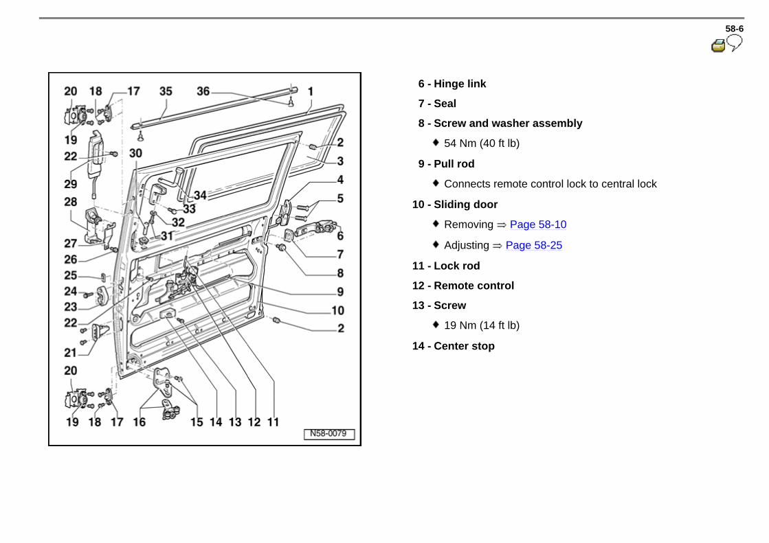
58-6
6 - Hinge link
7 - Seal
8 - Screw and washer assembly
54 Nm (40 ft lb)
9 - Pull rod
Connects remote control lock to central lock
10 - Sliding door
Removing Page 58-10
Adjusting Page 58-25
11 - Lock rod
12 - Remote control
13 - Screw
19 Nm (14 ft lb)
14 - Center stop

58-7
15 - Screw
19 Nm (14 ft lb)
16 - Lower roller guide assembly
17 - Latch pin
Adjusting Page 58-31
18 - Screw
19 Nm (14 ft lb)
19 - Striker
20 - B pillar
21 - Right rear door contact switch (sliding door) -F7-
22 - Recessed screw
8 Nm (71 in. lb)
23 - Striker
24 - Screw
19 Nm (14 ft lb)

58-8
25 - Trim plate
26 - Screw
19 Nm (14 ft lb)
27 - Tensioning spring
28 - Outside door handle
Removing Page 58-39
29 - Inside door handle
30 - Lock knob
Screwed onto pull rod
31 - Recessed screw
12 Nm (9 ft lb)
32 - Washer
33 - Recessed screw
12 Nm (9 ft lb)

58-9
34 - Upper roller guide assembly
35 - Profile seal
Clipped and glued
36 - Clip

58-10
Sliding door, removing
- Remove Phillips screw -1-, pull end piece -2- off guide rail.
- Mark position of lower roller guide.
- Remove Phillips screws -1-.

58-11
- Lower sliding door at front until upper roller guide can be removed from guide rail.
- With second technician, guide sliding door back -arrow- until hinge link -1- is out of guide rail -2-.

58-12
Sliding door Assembly overview from 04.01
1 - Window border
is damaged when removed
2 - Rubber buffer
3 - Sliding door window
adhered (positive engagement): removing and installing page 64-8
Special equipment, sliding window: servicing page 64-32
4 - Central lock
removing page 58-24
5 - Bolt
19 Nm

58-13
6 - Hinge armature
7 - Seal
8 - Bolt
Qty. 2
54 Nm
9 - Latch actuator rod
Connection from remote control to central lock
10 - Sliding door
removing Page 58-17
adjusting Page 58-32
11 - Locking rod
12 - Remote control
13 - Bolt
19 Nm
14 - Center stop

58-14
15 - Bolt
19 Nm
16 - Bolt
19 Nm
17 - Lower roller guide
18 - Latch pin
adjusting Page 58-36
19 - Bolt
19 Nm
20 - Catch plate
21 - B-pillar
22 - Right Rear Side/Sliding Door Contact Switch -F7-
23 - Bolt
8 Nm
24 - Catch plate
25 - Bolt
19 Nm

58-15
26 - Collar
27 - Bolt
19 Nm
28 - Tension spring
29 - Outside door handle
removing page 58-25
30 - Inside door handle
31 - Lock knob
threaded onto pull rod
32 - Bolt
12 Nm
33 - Washer
34 - Bolt
12 Nm

58-16
35 - Upper roller guide
36 - Seal profile
clipped in and adhered
37 - Clip

58-17
Sliding door, removing from 04.01
- Remove screw -1- and pull off end piece -2- from guide rail.
- Mark adjustment of lower roller guide -arrow-.
- Remove bolts -1-

58-18
- Lower sliding door far enough at front, so that the upper roller guide can be removed from the guide channel.
- With help from a second technician, guide sliding door back until hinge armature -1- slides out of guide rail -2-.

58-19
Door stop, removing
- If applicable, remove door step insert and Foot well Light with Delay Switch -W23-, Page 58-22 .
- Place sliding door in half-opened position.
- Remove screws -1- and pull door stop -2- downward out of guide channel.
Tightening torque:
19 Nm (14 ft lb)

58-20
Sliding door, adjusting (up to 12.95)
Sliding door adjusting (from 01.96) Page 58-25
- Remove sliding door molded trim and/or sliding door lower trim
Repair Manual, Body Interior, Repair Group 70
Hinge link, adjusting
- Loosen striker -1- by loosening screws -2-.
- Close sliding door and loosen bolt -1- from inside vehicle.
- Have a second technician lift sliding door, push hinge fitting with hex bolts -1- and guide tab -2- as far forward as possible.
- Tighten hex bolt -1-.
Tightening torque:
Bolt -1- = 58 Nm (43 ft lb)

58-21
Lower roller guide, adjusting
Front Height of sliding door incorrect
Sliding door does not match B-pillar outer contour
If sliding door does not match B-pillar outer contour adjust with Phillips screws -2- as follows:
Vehicles without door step insert
- If sliding door height is incorrect, loosen screws -1-, align sliding door as required -arrow-.
Tightening torque:
Screw -1- = 19 Nm (14 ft lb)
- Press plastic cap -1- out of step from below.

58-22
Vehicles with Foot well Light with Delay Switch -W23-
- If applicable, pry out Foot well Light with Delay Switch -W23- -1- and disconnect connectors.
- Unclip door step insert -1- from outside -arrows-, installation position, lift upward out of clips -2-.

58-23
Continued, all vehicles
Upper roller guide, adjusting
- Loosen Phillips screws -2-, press sliding door against roller guide -1- -arrow-, tighten only screw -2- on door side.
- Close sliding door carefully.
- Loosen screw -2- carefully while second technician outside indicates when sliding door is flush with B-pillar.
- Tighten both screws -2-.
Tightening torque:
Screws -2- = 19 Nm (14 ft lb).
Top front of sliding door does not match outer B-pillar contour.
- Loosen bolt -1- and slide upper roller guide -2- on bracket -3- -arrows- until top front of sliding door matches outer B-pillar contour.
Tightening torque:
Bolt -1- 8 Nm (71 in. lb).

58-24
Striker, adjusting
- Striker -1- can move horizontally -arrow- after loosening Phillips screw -2-.
Tightening torque:
Screws -2- = 19 Nm (14 ft lb)
- Adjust striker -1- so recess on remote control with turn clip is concentric -arrows- to striker (door must not be raised or pressed down).
Sliding door must have no free play when closed.

58-25
Sliding door, adjusting (from 01.96)
Sliding door, adjusting (up to 12.95) Page 58-20
- Remove sliding door molded trim and/or remove lower door trim.
Repair Manual, Body Interior, Repair Group 70
Hinge, adjusting
- Loosen latch striker -1- by loosening phillips screws -2-.
- Close sliding door, loosen hex bolts -1- from inside vehicle.
- Have second technician lift sliding door and push hinge as far forward as possible.
- Tighten hex bolts -1-.
Tightening torque:
Bolt -1- = 58 Nm (43 ft lb)

58-26
Lower roller guide, adjusting
Sliding door height not correct
Sliding door outer contour does not match B-pillar
If sliding door contour does not match B-pillar, make adjustments with Phillips screws -2- as follows:
Vehicles without step insert
- To adjust height, loosen Phillips screws -1- and align accordingly -arrow-.
Tightening torque:
Phillips screw -1- = 19 Nm (14 ft lb)
- Press plastic cap -1- out of step from below.

58-27
Vehicles with step insert
- Pry step light -W23- -1- out, if applicable, disconnect connector.

58-28
- Unclip step trim -1- at outside -arrows-, lift up out of clips -2-.

58-29
Continued, all vehicles
With help of second technician
Upper roller guide, adjusting
- Loosen Phillips screws -2-, press sliding door against roller guide -1- -arrow-, tighten one screw -2- next to door.
- Carefully close door.
- Loosen screw -2- enough to adjust contour with outer B-pillar, then tighten both screws -2-.
Tightening torque:
19 Nm (14 ft lb)
Sliding door top front does not match B-pillar contour
- Loosen hex recess bolt -1-, slide upper roller guide -2- on bracket -3- -arrows- until top front of sliding door matches outer B-pillar contour. Tightening torque: Recessed bolt -1- = 8 Nm (71 in. lb).

58-30
Latch striker, adjusting
- Loosen Phillips screws -2-, striker can now slide horizontally -arrow-.
Tightening torque:
Screws -2- = 19 Nm (14 ft lb)
- Adjust latch striker -1- so recess on central lock engages with catch in center of striker -arrow- (door must not be raised or pressed).
Door must have no free play when closed.

58-31
Latch pin, adjusting
Latch pin must face inside of vehicle, when installing
- Loosen screws -1- enough to move latch pin -2-.
- Close door slowly and check latch pin -1- position to catch plates -2-, latch pins must be parallel to catch plates.
- Close door completely to confirm adjustment.
- Open door and tighten screws.
Tightening torque:
Screws -1- = 19 Nm (14 ft lb)

58-32
Adjusting sliding door from 04.01
- Remove roller guide trim; front frame trim and cover for sliding door adjustment.
Repair Manual, Body Interior; Repair Group 70; Door trim, sliding door form trim - assembly overview
Closing force reduction, adjusting
There must be a distance of approx. 1 to 2 mm between catch plate ( pos. 24 , Page 58-14 ) and B-pillar pressure plate in closed condition (visual check).
If this is not the case, all listed work steps must be performed in the following sequence:
- Adjust hinge armature Page 58-33 .
- Adjust lower roller guide Page 58-33 .
- Adjust upper roller guide Page 58-34 .
- Adjust latch striker Page 58-35 .
- Adjust latch pin Page 58-36 .
- Adjust rubber buffer Page 58-37 .

58-33
Hinge armature, adjusting
Lower roller guide, adjusting
- Close sliding door and loosen bolts -1- from vehicle interior.
- Have a second technician lift sliding door and slide hinge armature with bolts as far forward as possible.
- Tighten bolts -1-.
Tightening torque: Bolt -1- = 54 Nm
Sliding door height at front is not correct
Sliding door is not flush with outside contour of B-pillar
- Remove latch pin on sliding door-side.
If the front of the sliding door is not flush with the outside contour of the B-pillar, the adjustment must be performed via bolts -2- as follows:
- If the height adjustment of the sliding door is not correct, loosen bolts -1- and adjust sliding door respectively -arrow-.
Tightening torque: Bolt -1- = 19 Nm

58-34
Upper roller guide, adjusting
- Loosen bolts -2-, adjust sliding door to roller guide -1- -arrow- and pre-tighten both bolts slightly.
- Carefully close sliding door and check seating of sliding door from outside. If necessary, repeat procedure until the sliding door is flush with the outer contour of the B-pillar.
- Carefully open sliding door and tighten both bolts -2-.
Tightening torque: Bolts -2- = 19 Nm
Top front of sliding door is not flush with the outer contour of the B-pillar
- Loosen bolt -1- and then slide upper roller guide -2- on bracket -3- to adjust -arrows-, until top front of sliding door is flush with the outer contour of B-pillar.
Tightening torque: Bolt -1- = 8 Nm

58-35
Latch striker, adjusting
- Latch striker -1- can be adjusted horizontally -arrow- after loosening bolts -2-.
Tightening torque: Bolts -2- = 19 Nm
- Adjust latch striker -1- so that the cutout of the central lock with lock mechanism engages centrally in latch striker -arrows- (do not lift up or press down on door). Sliding door must project out approx. 1 to 2 mm and not have any play in closed condition to C-pillar (wind noise).

58-36
Latch pin, adjusting
- Install latch pin on sliding door-side.
When installing, make sure the points of latch pin point toward the vehicle interior.
- Loosen bolts -1- until latch pin -2- can be moved.
- Slowly close sliding door and check position of latch pin -1- to catch plates -2- - latch pins must be parallel to the catch plates -.
- Close sliding door completely, therefore adjusting the latch pins.
- Open sliding door and tighten screws
Tightening torque: Screws -1- = 19 Nm.
- Carefully close sliding door once again to check whether the latch pins run into the catch plates in a centered manner.

58-37
Rubber buffers, adjusting
- Rubber buffers at rear top and bottom of sliding door must be adjusted by threading in or out so that they make light contact.
- Do not use the rubber buffers to adjust the sliding door.

58-38
Remote control lock, removing
Repair Manual, Body Interior, Repair Group 70. - Remove sliding door trim and/or remove lower sliding door trim
- Disconnect pull rod -1- from remote control lock -2-.
- Remove remote control lock -1- by removing screws and disconnecting pull rod -2- at remote control.
Tightening torque:
Screw = 19 Nm (14 ft lb).

58-39
Outside door handle, removing
Repair Manual, Body Interior, Repair Group 70 - Remove sliding door trim and/or remove lower sliding door trim.
- Loosen inner mechanism by removing bolts -2-, remove by pulling up.
- Remove Bolts and disconnect pull rod -2-. Push remote control to one side.
Tightening torque:
Bolts -1- = 8 Nm (71 in. lb)

58-40
- Remove screw -1- and disconnect tension spring -2-.
Tightening torque:
Screw -1- = 19 nm (14 ft lb)

58-41
Lock cylinder, removing (sliding door)
Repair Manual, Body Interior, Repair Group 70. - Remove sliding door trim and/or remove lower sliding door trim.
- Remove outer door handle Page 58-39 .
- Remove spring pin -1-.
- Remove casting -2- off four-sided shaft.
- Remove outer spring -3-.
- Remove lock cylinder -4- with key -5- inserted.
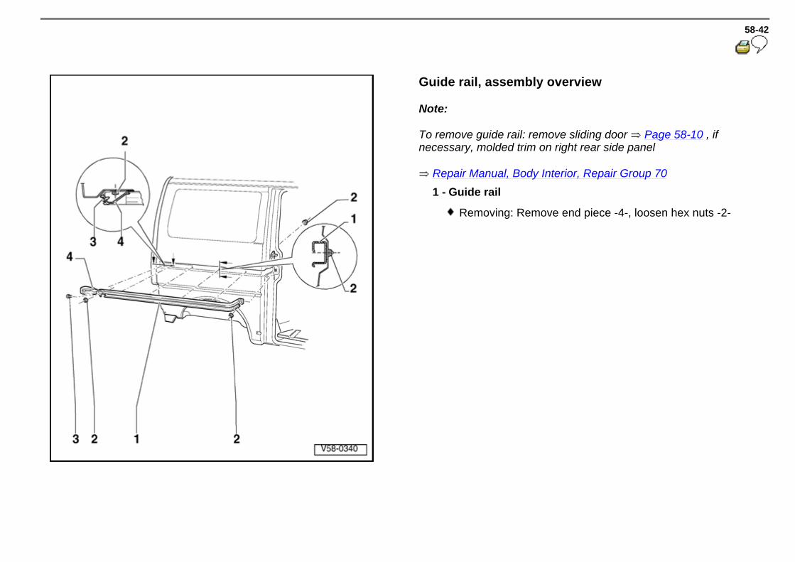
58-42
Guide rail, assembly overview
Note:
To remove guide rail: remove sliding door Page 58-10 , if necessary, molded trim on right rear side panel
Repair Manual, Body Interior, Repair Group 70 1 - Guide rail
Removing: Remove end piece -4-, loosen hex nuts -2-

58-43
2 - Hex nuts
8 Nm (71 in. lb)
3 - Phillips screws
4 - End piece

63-1
Front bumper Assembly overview (up to 12.95)
Front bumper, removing and installing (from 01.96) (long front end) Page 63-2
Front bumper, removing and installing (from 01.96) (short front end) Page 63-4
1 - Cover
2 - Bolt w/washer
10 Nm (7 ft lb)
3 - Front bumper
Removing: Pull/drive pins -4- out and pull bumper parallel out of guides -5-
Installing: Slide bumper parallel onto guides -5-, secure by driving in pins -4- flush
4 - Pin
5 - Guide

63-2
Front bumper, removing and installing (from 01.96) (long front end)
Front bumper, removing and installing (from 01.96) (short front end) Page 63-4
Front bumper, removing and installing (up to 12.95) Page 63-1
1 - Cover
- Remove radiator grille with trim frame page 66-2.
- Remove torx screws -2- and -3-.
- Pull cover forward out of guides.
Note center faster (arrow)
2 - Torx screw T 30 (4x)
6 Nm (53 in. lb)

63-3
3 - Torx screw T25 (2x)
1.2 Nm (11 in. lb)
4 - Bumper beam
Disconnect right side then left
5 - Guide bracket
To remove/install bumper beam, push/pull beam straight (parallel) out of guide bracket
6 - Rivet
7 - Hex screw (4x)
1.5 Nm (13 in. lb)
8 - Cover bracket

63-4
Front bumper, removing and installing (from 01.96) (short front end)
Front bumper, removing and installing (up to 12.95) Page 63-1
Front bumper, removing and installing (from 01.96) (long front end) Page 63-2
1 - Cover
Material - PP/EPDM
Removing
- Pry out caps -9-, remove combination hex screw and washer assemblies -10-, Torx screws -8-
2 - Bumper bracket

63-5
3 - Bumper guide bracket
To remove/install bumper beam, push/pull beam straight (parallel) out of guide bracket
4 - Rivet
5 - Blind rivet
6 - Bumper bracket
7 - Cover guide bracket
8 - Torx screw T25 (2x)
1.2 Nm (11 in. lb)
9 - Cap, hex screw
10 - Screw / washer assembly
6.5 Nm (58 in. lb)

63-6
Rear bumper Assembly overview (up to 12.95)
Rear bumper, removing and installing (from 01.96) Page 63-8
1 - Rear bumper
2 - Cover
3 - Bolt w/washer
15 Nm (11 ft lb)
4 - Bolt w/washer
15 Nm (11 ft lb)
5 - Pin
Replacement part includes -5- and -6-
6 - Expanding clip
Replacement part includes -5- and -6-

63-7
7 - Bumper bracket
8 - Bolt w/washer
110 Nm (81 ft lb)
9 - Pin
10 - Guide
To remove and install, push in or slide out bumper parallel from guide (left and right)
11 - Sealing washer

63-8
Rear bumper, removing and installing (from 01.96)
Rear bumper, removing and installing (up to 12.95) Page 63-6
1 - Cover
- Remove torx screws -8-, hex screws -7-.
- Remove bumper with rail -3- from guides -6-.
- Remove torx screws -9-.
- Pull cover from rail with brackets -3-.
Note center fastening point
2 - Bumper beam
When removing, disconnect right side then left
3 - Rail with bracket

63-9
4 - Sleeve
5 - Expansion clip
6 - Bumper guide bracket
To remove/install bumper beam, push/pull beam straight (parallel) out of guide bracket
7 - Hex bolt with washer
15 Nm (11 ft lb)
8 - Torx screw T25 (2x)
1.2 Nm (11 in. lb)
9 - Torx screw T30
6 Nm (53 in. lb)