REPAIR - Pitt Autopittauto.com/.../Wisconsin_V460D_V461D_V465D_Repair_WM20250.pdf · A factory test...
46
WISCONSIN MODELS V465D V41NID, V461D REPAIR ~ WISCONSIN MOTORS, LLC
-
Upload
nguyenlien -
Category
Documents
-
view
224 -
download
2
Transcript of REPAIR - Pitt Autopittauto.com/.../Wisconsin_V460D_V461D_V465D_Repair_WM20250.pdf · A factory test...

WISCONSINMODELS V465D
V41NID, V461D
REPAIR
~ WISCONSINMOTORS, LLC

FOREWORD
Good operation and a planned maintenance program as outlined in this manual are vital inobtaining maximum engine performance and long engine life. The instructions on the followingpages have been written with this in mind, to give the operator a better understanding of thevarious problems which may arise, and the manner in which these problems can best be solvedor avoided.
The operator is cautioned against the use of any parts, other than genuine Wisconsin parts,for replacement or repair. These parts have been engineered and tested for their particularjob, and the use of any other parts may result in unsatisfactory performance and short enginelife. Wisconsin distributors and dealers, because of their close factory relations, can renderthe best and most efficient service.
THE LIFE OF YOUR ENGINE DEPENDS ON THE CARE IT RECEIVES.
The MODEL, SPECIFICATION and SERIAL NUMBER of your engine must be given whenordering parts. The MODEL and SPECIFICATION number are on the name plate. The SERIALNUMBER is stamped either on the crankcase or the engine’s identification tag.
Copy the MODEL, SPECIFICATION and SERIAL NUMBER in the spaces provided below sothat it will be available when ordering parts.
MODEL SPECIFICATION
SERIAL NUMBER
To insure prompt and accurate service, the following information must also be given:
1. State EXACTLY the quantity of each part and part number.
2. State definitely whether parts are to be shipped by express, freight or parcel post.
3. State the exact mailing address.

IMPORTANT
READ THESE INSTRUCTIONS CAREFULLY
All points of operation and maintenance have been covered as carefully as possible, but if furtherinformation is required, send inquiries to the factory for prompt attention.
When writing to the factory, ALWAYS GIVE THE MODEL, SPECIFICATION AND SERIALNUMBER of the engine referred to.
Starting and Operatinq New Engines
Careful breaking-in of a new engine will greatly increase its life and result in troublefree operation.A factory test is not sufficient to establish the polished bearing surfaces, which are so necessaryto the proper performance and long life of an engine. These can only be obtained by running anew engine carefully and under reduced loads for a short time.
¯ Be sure the engine is filled to the proper level with a good quality engine oil.
¯ For proper procedures to follow when breaking-in a new engine, see ’Testing Rebuilt Engine’.
The various bearing surfaces in a new engine have not been glazed, as they will be with continuedoperation, and it is in this period of "running in" that special care must be exercised, otherwisethe highly desired glaze will never be obtained. A new bearing surface that has once beendamaged by carelessness will be ruined forever.

IMPORTANT SAFETY NOTICE
Proper repair is important to the safe and reliable operation of an engine. This Repair Manualoutlines basic recommended procedures, some of which require special tools, devices or workmethods.
Improper repair procedures can be dangerous and could result in injury or death.
READ AND UNDERSTAND ALL SAFETY PRECAUTIONS ANDWARNINGS BEFORE PERFORMING REPAIRS ON THIS ENGINE
Warning labels have also been put on the engines to provide instructions and identify specifichazards which, if not heeded, could cause bodily injury or death to you or other persons. Theselabels identify hazards which may not be apparent to a trained mechanic. There are manypotential hazards for an untrained mechanic and there is no way to label the engine against allsuch hazards. These warnings in the Repair Manual and on the engine are indentified by thissymbol:
z WARNING
Operations that may result only in engine damage are identified in the Repair Manual by thissymbol:
,&CAUTIONWisconsin Motors, LLC cannot anticipate every possible circumstance that might involve apotential hazard; therefore, the warnings in this manual are not all inclusive. If a procedure,tool, device or work method not specifically recommended by Wisconsin Motors, LLC, is used,you must satisfy yourself that it is safe for you and others. You should also ensure that theengine will not be damaged or made unsafe by the procedures you choose.
IMPORTANT: The information, specifications and illustrations in this manual are basedon information that was available at the time it was published. The specifications,torques, pressures of operation, measurements, adjustments, illustrations and otheritems can change at any time. These changes can affect the service given to theproduct. Get the complete and most current information before starting any job. Forparts, service, or information, contact Wisconsin Motors, LLC, Memphis, Tennessee.

WARNINGMost sub-systems used in conjunction with Wisconsin Motors, LLC, industrial enginesincluding (but not limited to) radiators, hoses, fans, fuel tanks, fuel lines or other fuel systemcomponents, batteries, electrical connections or other electrical components, clutches,transmissions, hydraulic pumps and generators, are not supplied by Wisconsin Motors, LLC.these items are provided by the manufacturer of the end item in which the engine is used.
Some of the dangers associated ’with servicing such items are generally mentioned in thismanual; however, the appropriate handbooks and safety instructions provided by the manufac-turer of the end item should always be consulted prior to the undertaking of any work on sub-systems attached to the engine, to avoid any hazards inherent to these sub-systems.
Read and observe all individual safety warnings as you use this manual to operate, service orrepair your engine.
Always exercise caution wheneve=" working with an engine or any associated system.
Injuries may be caused by lack of care when working with, or near, moving parts, hot parts,pressurized systems, electrical equipment, or fuel systems.
Always wear eye and hearing protection when working on or near engines.
Improper attire such as loose clothing, ties, rings, soft shoes or bare feet could be hazardous andshould be avoided when servicing engines.
Use or service of the engine (including the use of modified parts or materials) not in accordancewith manufacturer’s specifications could damage your engine or cause personal injury.
WARNINGSome equipment and materials used in the overhaul or maintenance of an engine such asmachine tools, electrical equipment, compressed air, solvents, gasoline or other fuels may bedangerous and can cause injury. Always observe safety precautions.
iii

SAFETY PRECAUTIONS
¯ Never fill fuel tank while engne is running or hot;avoid the possibility of spilled fuel causing a fire.
¯ Always refuel slowly to avoid spillage.
¯ When starting engine, maintain a safe distancefrom moving parts of equipment.
¯ Do not start engine with clutch engaged.
¯ Do not spin hand crank when starting. Keepcranking components clean and free from conditionswhich might cause the crank jaw to bind and notrelease properly. Oil periodically to prevent rust.
¯ Never run engine with governor disconnected, oroperate at speeds in excess of 2400 R.P.M. load.
Do not operate engine in a closed building unlessthe exhaust is piped outside. This exhaust containscarbon monoxide, a poisonous, odorless andinvisible gas, which if breathed causes seriousillness and possible death.
Never make adjustments on machinery while it isconnected to the engine, without first removing theignition cable from the spark plug. Turning themachinery over by hand during adjusting orcleaning might start the engine and machinery withit, causing serious injury to the operator.
Precaution is the best insurance againstaccidents.
Keep this book handy at all times,familiarize yourself with the operating instructions.
Model V465D3-3/4" Bore m 4" Stroke177 cu. in. Displacement
Models V461 D, V460D
3-1/2" Bore- 4" Stroke154 cu. in. Displacement
2

CONTENTSAir Cleaner, Pre-Cleaner ....................................................... 11,12Alternator -- Belt Driven .......................................................... 34
Bearing -- Center Main ............................................................. 11
Breather Cap ..............................................................................10
Carburetor Adjustment .............................................................. 12
Carburetor Service
Zenith Model 87A8 ........................................................ 35-37
Clutch Adjustment ..................................................................... 18
Clutch Power Take-off ............................................................... 18
Clutch Reduction Unit ................................................................ 19
Compression -- Restoring .......................................................... 16
Cooling .........................................................................................8
Dieseling, Anti-Diesel Valve ..................................................... 10
Disassembly and Reassembly .................................................... 23
Accessories ..........................................................................23
Camshaft ..............................................................................30
Camshaft Gear ..................................................................... 30
Carburetor and Manifold ..................................................... 25Center Main Bearing, Roller Type (Older Models) .............. 32
Center Main Bearing, Shell Type ......................................... 30Connecting Rod and Piston .................................................. 28
Crankshaft and Main Bearing Plate ..................................... 31
Cylinder Barrel ....................................................................27
Cylinder Head ......................................................................27
Cylinder Shrouding .............................................................. 25
Distributor and Accessory Drive .......................................... 24Engine Supports and Oil Pan ............................................... 26Flywheel ..............................................................................23Flywheel Shroud .................................................................. 24Fuel Pump ............................................................................25Gear Cover ..........................................................................25
Gear Train ............................................................................26Generator .............................................................................24
Governor ...............................................................................25Oil Pressure Reducing Valve ............................................... 32
Oil Pressure Relief Valve ...................................................... 31Oil Pump ..............................................................................26
Idler Gear and Shaft .............................................................. 31
Piston ...................................................................................28Piston Ring and Rod Clearance Chart .................................. 29
Piston Rings .........................................................................28Valve Guides and Seat Inserts ............................................. 30Valves ..................................................................................29Rocker Arm Assembly ........................................................ 30
Distributor Maintenance ............................................................ 14Electric Wiring Circuits ............................................................. 15Electrical Wiring Diagrams
Distributor Ignition with Alternator ..................................... 34
Distributor Ignition with Generator (Older Models) ............ 14
Magneto Ignition ................................................................. 15
Firing Order ...............................................................................12
Fuel ..............................................................................................9
Fuel Mixture ..............................................................................20
Fuel Pump and Priming ............................................................... 9Gasoline Strainer ....................................................................... 12
General Information and Design .................................................. 8
Generator (Older Models) .......................................................... 15
Governor Adjustment and Operation ......................................... 17
Horsepower .................................................................................8
Ignition Spark ............................................................................16
Ignition System ..........................................................................12
Illustrations, Engine
Take-off View ....................................................................... 5
Fan End View ........................................................................ 5
Sectional Views .................................................................. 6,7
Lubrication System .............................................................. 11
Keep Engine Clean ...................................................................... 3
Lubrication ..................................................................................8
Lubrication System ................................................................. 8,11
Magneto ServiceFairbanks-Morse Type FM-X4B7D ..................................... 38
Oil Filter ....................................................................................10
Oil -- Grade of and Service Classification .................................. 9
Oil Pressure and Adjustment ...................................................... 10
Rotation .......................................................................................8
Rocker Arm Covers ................................................................... 17
Safety Notice ..........................................................................ii-iii
Safety Precautions ....................................................................... 2
Safety Switch -- High Temperature .......................................... 19
Solid State Ignition Distributors ...................................... 12, 3940
Spark Plugs ................................................................................16
Starting Motor -- Electric ........................................................... 9
Starting and Operating Instructions .............................................. 8
Starting and Operating New Engines ............................................ i
Starting Procedure ....................................................................... 9Stopping Engine -- Vapor Lock ................................................ 10
Storage of Engine for Winter ..................................................... 21Testing Rebuilt Engine .............................................................. 23
Timing .......................................................................................12
Distributor Timing ............................................................... 13
Magneto Timing .................................................................. 15
Neon Lamp Timing ............................................................. 14
Timing Instructions .................................................................... 13
Timing Marks ............................................................................ 13
Troubles -- Causes and Remedies ............................................. 20
Backfiring Through Carburetor ............................................ 21Compression ........................................................................20
Engine S tops ........................................................................21
High Oil Pressure ................................................................. 21
Ignition ................................................................................20
Knocking .............................................................................21
Low or No Oil Pressure ....................................................... 21
Missing ................................................................................20
Overheating .........................................................................21
Starting Difficulties -- Fuel Mixture ................................... 20
Surging or Galloping ........................................................... 21
Valves -- Grinding ............................................................... 29,30
Valve Tappet Adjustment .......................................................... 16
Warm-Up Period -- Overspeeding ............................................ 10

KEEP EN( INE CLEANPREVENT OVERHEATING
This engine is cooled by a flow of air from a combi-nation fan-flywheel, encased in a sheet metal shroud-ing. The air is divided and directed by ducts andbaffle plates to insure uniform cooling of both banksof cylinders. If dirt and chaff are allowed to accumu-late in the cylinder shrouding or in the V betweencylinder banks, the flow of cooling air will be re-stricted, creating an overheating condition, whichcould result in costly repairs.
The rotating screen, illustrated in Fig. B, is recom-mended for engines operating in dusty and dirty con-ditions. The screen deflects foreign materials awayfrom the air intake opening and helps maintain maxi-mum cooling efficiency. Keep rotating screen clean.Even a small section of screen clogged up with dirtwill restrict the intake of cooling air enough to bringabout an overheating condition.
With reference to Figures A and B; follow these fewcleaning and maintenance instructions to insure trou- ’ble free and satisfactory engine performance.
1. Cylinder head covers can be removed by releasingsnap clips and unscrewing wing nut. Clean out alldirt and chaff from interior of shroud and from be-tween fins of cylinders and heads.
2. Remove dirt an,~ chaff from cylinder heat deflectorsat manifold ports.
3. Keep space between cylinder banks clean.
4. Replace this oil filter cartridge every other oilchange. If operating conditions are extremely dustyreplace cartridge every oil change. See Oil Filterinstructions, Page 10.
5. Rotating screen must be kept clean. Accumulateddirt caked on screen will restrict cooling.
6. Read instructions on air cleaner regarding its care.The entire air cleaner should be removed from theengine at least once a year, and washed in a sol-vent to clean out dirt gathered in the back firetrap and filter element.
7. The collector type pre-cleaner must be emptied ofaccumulated dirt frequently, depending on dustconditions. Do not use oil or water in pre-cleaner,this must be kept dry.
8. Do not allow shrouding to become damaged or bad-ly dented as this will retard air flow.
Never operate engine with air shrouding removed.
Every 4 to 8 hours, depending on dust conditions,check air cleaner and change oil. See Page 12.
Every 8 hours check crankcase oil level. Keep filledto full mark on oil gauge saber, but no more. Every50 hours drain crankcase and refill with fresh oil.See Lubrication, Pages 8 and 9.
4
Fig. A
6
Fig. B

ROCKER ARM COVERS
OIL FILLER ANDBREATHER CAP
CYLINDER NU
VOLT AGE
IGNIT ION
GENE
PREoCLEANE
OIL BATHAIR CLEANER~
STARTING SO
STARTING MOTOR~
OIL FILTER
OIL DRAIN PLUG
MUFFLER
DISTRIBUTOR
ANTI-DIESE LINGSOLENOID
BUTTON
VARIABLE SPEED~IOR CONTROL
PRESSURE GAUGE
- STARTERSWITCH
fWHEEL SHROUD
FUEL PUMPHEAT SHIELD
GASOLINESTRAINER
PUMP
L GAUGESABER
-OPTIONAL-OIL GAUGE AND
FILLER LOCATION
Fig. 1

IGNITION COl.
GENERATOR
VOLTAGE REGULATOR
DISTRIBUTOR
;CESSORY DRIVE ASSEMBLY
CARBURETOR~
GOVERNOR ASSEMB~
ANTI-DIESELING~SOLENOID
FLYWHEELAIR SHROUD
CAMSHAFTTHRUST PLUNGI
OIL
MAIN BEAI:
IDLER
GOVERNOR:ADJUSTING SCREW
~LEVER ~/SPRING
LOCKNUT~
I t.~,~_~
UEL PUMP
--CAMSHAFT
~-MAIN BEARING
HAND CRANK
FAN-FLYWHEELDIL PUMP
SECTIONAL VIEWS OF ENGINE6

~OIL PRESSURE REDUCING VALVE
rOlL BATH AIR CLEANER/ PRE- CLEANER\
EXHAUST
/ ROTATOR
,~TTAPPETADJUSTING
SCREW
HI- TEMPSAFETY
EXHAUST MUFFLER
/ GASOLINE STRAINER
//~-OIL FILLER AND
BREATHER CAP
SPARK PLUG-
\\
//
L DIPSTICK
STARTING SOLENOID
STARTING MOTOR
OIL PRESSURE jRELIEF VALVE~ ~
OIL FILTEROIL DRAIN PLUG
SHAFTLOCK-SCREWS
~CENTERMAIN BEARING
MODELS V-460D, V-461D AND V-465D

GENERAL INFORMATION AND DESIGN
Wisconsin engines are of the four cycle type, in whicheach of the four operations of intake, compression, ex-pansion and exhaust requires a complete stroke. Thisgives one power stroke per cylinder for each two revolutionsof the crankshaft.
ROTATION
The rotation of the crankshaft is clockwise whenviewing the flywheel or cranking end of the engine.This gives counter-clockwise rotation when viewingthe power take-off end of the engine. The flywheelend of the engine is designated the front end, and thepower take-off end, the rear end of the engine.
COOLING
Cooling is accomplished by a flow of air, circulatedover the cylinders and heads of the engine, by acombination fan-flywheel encased in a sheet metalshroud. The air is divided and directed by ducts andbaffle plates to insure uniform cooling of all parts.
Never operate an engine with any part of the
shrouding removed, -- this will retard the aircooling.
Keep cylinder and head fins free from dirt and chaff.
Improper circulation of cooling air will cause engine
to overheat.
CARBURETOR
The proper combustible mixture of gasoline and air,is furnished by a balanced carburetor, giving correctfuel to air ratios for all speeds and loads.
IGNITION
The spark for ignition of the fuel mixture is directed fromthe coil to the spark plugs, at the proper time, by a distribu-tor. Electric starter and alternator are furnished withdistributor ignition.
Magneto ignition can be furnished in place of distri-butor, when specified. The high tension magneto used,is fitted with an impulse coupling that provides apowerful spark for easy starting.
LUBRICATION SYSTEM
A gear type pump provides pressurized lubrication tothe connecting rod bearings, camshaft bearings, tap-pets, valve train and to an oil spray nozzle in the gearcover. The spray nozzle lubricates the governor andgear train. The oil expelled from these areas form amist which lubricates the cylinder walls and the anti-friction crankshaft bearings.
All of the circulated oil passes thru a full.flow oilfilter. Crankcase impurities are collected in the filterelement, thereby minimizing friction and reducingwear to critical moving parts of the engine.
GOVERNOR
A governor of the centrifugal flyball type controlsthe engine speed by varying the throttle opening tosuit the load imposed upon the engine. All enginesare equipped with either fixed speed governors, avariable speed regulator to control the governedspeed of the engine, or an idle control.
HORSEPOWER CHART
R.P.M.
16001800200022002400260028003000
V-460D V-465DV-461D
40.9 41.645.6 47.550.2 52.453.8 56.756.8 60.058.4 63.060.2 64.560.5 65.9
HORSEPOWER
The horsepower given in the above chart is for anatmospheric temperature of 60° Fahrenheit, at sealevel, and at a Barometric pressure of 29.92 inchesof mercury.
For each inch lower Barometer reading, deduct 3~/2%from above horsepower.
For each 10° higher temperature, there will be a re-duction in horsepower of 1%.
For each 1000 ft. altitude above sea level, there willbe a reduction in horsepower of
The friction in new engines cannot be reduced to theultimate minimum during the regular block test, butengines will develop at least 85 per cent of maximumpower when shipped from the factory. The power willincrease as friction is reduced during a few days ofoperation. The engine will develop approximately 95%of power shown on chart when friction is reduced toa minimum.
For continuous operation, limit to 80% of horsepowershown, as a safety factor.
INSTRUCTIONS FORSTARTING AND OPERATING
LUBRICATION
Before starting a new engine, fill crankcase with thecorrect grade of lubricating oil, as specified in "Gradeof Oil" chart. Fill through the breather tube openingwith 6 quarts of oil, and check level by means of theoil gauge saber. When replacing oil filter, an addi-tional | quart of oil is required.
For run-in of new engines, use same oil as recom-mended in Grade of Oil Chart.
The standard oil gauge saber is located on the lefthand side, below the oil filler-breather tube. SeeFig. 1. When specified, a saber can be furnished onthe opposite side, behind the starting motor.

High grade oil of the body suited to the requirementsof your engine is the most important single item inthe economical operation of the unit, yet it is thecheapest item of operating cost. Select your oil solelyon quality and suitability - never o~ price - forno one thing is so sure to bring about unsaUsfactoryperformance and unnecessary expense as incorrectlubrication. High-grade highly refined oils, corres-ponding in body to the S. A. E. Viscosity Numberslisted in Grade of Oil Chart will prove economicaland assure long engine life.
SERVICE CLASSIFICATION OF OIL
In addition to the S.A.E. Viscosity grades, oils are alsoclassified according to severity of engine service. Use oilsclassified by the Americal Petroleum Institute as Service
SE, SFor SG. These types ofoil are for engines performingunder unfavorable or severe operating conditions such as:
high speeds, constant starting and stopping, operating inextreme high or low temperatures and excessive idling.
GRADE OF OIL
SEASON OR TEMPERATURE GRADE OF OIL
Spring, Summer or Fall SAE 30+ 120°F to + 40°F
Winter+ 40°F to + 15°F SAE 20-20W"I" 15°F to 0°F SAE 10WBelow Zero SAE 5W-20
Use Oils classified as Service SE, SF, SG or CCCrankcase Capacity 6 Qts.
Additional for Oil Filter I Qt.
For run-in of new engines, use same oil as recom-mended in Grade of Oil Chart.
Follow summer recommendations in winter if engineis housed in warm building.
Check oil level every 8 hours of operation.
The old oil should be drained and fresh oil addedafter every 50 hours of operation.
To drain oil, remove drain plug in oil pan at oil filterside. Oil should be drained while engine is hot, as itwill then flow more freely.
FUEL
The fuel tank should be filled with a good qualitygasoline, free from dirt and water. Some: of the poorergrades of gasoline contain gum which will deposit onvalve stems, piston rings, and in the various smallpassages in the carburetor, causing serious troublein operating, and in fact might prevent the enginefrom operating at all.
Use only reputable, well known brands ofREGULAR GRADE gasoline.
The gasoline should have an octane rating of at least90. Low octane gasoline will cause the engine to de-tonate, or knock, and if operation is continued underthis condiUon, cylinders will score, va~.ves will bum,
Fig. 2
pistons and bearings will be damaged, etc.
Be sure that air vent in tank cap is not plugged- thiswould impede the flow of fuel to the carburetor.
FUEL PUMP and PRIMING (Fig. 2)
The diaghragm type fuel pump is actuated by an ec-centric on the camshaft, as illustrated in cross sec-tional view of engine, page 6.
Hand Primer for hand crank engine is furnished as anoption, and is a necessary function when starting anew engine for the first time, or when engine has beenout of operation for a period of time. Gravity feed andelectric start engines do not require hand priming.
When priming, a distinct resistance of the fuel pumpdiaghragm should be felt when moving the hand leverup and down. If this does not occur, the engine shouldbe turned over one revolution so that the fuel pumpdrive cam will be rotated from its upper positionwhich prevents movement of the pump rocker arm.
Assuming the gasoline strainer is empty, approximate-ly 25 strokes of the primer lever are required to fillthe bowl. See Fig. 2. Aftef strainer bowl is full, anadditional 5 to 10 strokes are required to fill thecarburetor bowl. When carburetor is full the handprimer lever will move more easily.
STARTING
ELECTRIC STARTING MOTOR
A 12 volt starting motor with an attached startingsolenoid is provided as standard equipment on thismodel engine, unless otherwise specified.
Do not oil Bendix drive. Keep screw threads cleanand if necessary, lubricate with powdered graphite.
STARTING PROCEDURE
1. Check crankcase oil level and fuel supply. Openfuel valve.
2. Disengage clutch, if furnished.
3. New engines require priming; refer to "Fuel Pump"paragraph for instructions.
4. Set throttle about 1/2 open if variable speed gov-ernor control is furnished; with a two-speed con-trol, start in full load position.
5. Turn ignition-starting switch to ’start’ positionand at the same time pull out choke button onlysufficient to start the engine. Release choke but-ton to open position after engine starts, but re-

cl~oke if ~t tends to stop. Even a hot engine re-quires a momentary choking when starting. Whenengine starts release switch to ’run’ position.
If flooding should occur, continue cranking with thestarting motor, but with choke open (choke button in).
After engine starts; allow it to warm up a few minutesbefore applying load, as prescribed in ’Warm-UpPeriod’ paragraphs.
New engines; started for the first time, should be
"run-in" gradually to insure trouble-free service andlong engine life. Refer to "Starting and Operation ofNew Engine" instructions, on the inside front coverof this manual, for correct running-in procedure.
WARM-UP PERIOD
The engine should be allowed to warm up to operatingtemperature before load is applied. This requires onlya few minutes of running at moderate speed. Racingan engine or gunning it, to hurry the warm-up period,is very destructive to the polished wearing surfaceson pistons, rings, cylinders, bearings, etc., as theproper oil film on these various surfaces cannot beestablished until the oil has warmed up and becomesufficiently fluid. This is especially important on newengines and in cool weather.
Racing an engine by disconnecting the governor, or bydoing anything to interfere with the governed controlengine speed, is extremely dangerous. The governoris provided as a means for controlling the enginespeed to suit the load applied, and also as a safetymeasure to guard against excessive speeds, whichnot only overstrain all working parts, but which mightcause wrecking of the engine and possible injury tobystanders°
All parts of the engine are designed to safely with-stand any speeds which might normally be required,but it must be remembered that the stresses set up inrotating parts increase with the square of the speed.That means that if the speed is doubled, the stresseswill be quadrupled, and if the speeds are trebled, thestresses will be nine times as great.
Strict adherence to the preceding instructions cannothe too strongly urged, and greatly increased enginelife will result as a reword for these easily appliedrecommendations.
STOPPING ENGINE
To stop engine; turn ignition-starting switch to ’offposition.
If the engine has been running hard and is hot, do notstop it abruptly from full load, but remove the loadand allow engine to run idle at 1000 to 1200 R.P.M.for three to five minutes, depending on how hot theengine has been. This will reduce the internal tem-perature of the engine much faster, minimize valvewarping, and of course the external temperature, in-cluding the manifold and carburetor will also reducefaster, due to air circulation from the flywheel°
One of the main troubles caused by the abrupt shut-ting off of a hot engine is vapor lock. This will result
in hard starting, which can be overcome by chokingthe engine when cranking or waiting until the enginehas cooled off sufficiently to overcome the vapor lock.
ANTI-DIESEL VALVEHigh compression engines have a tendency to occa-
sionally diesel, after the ignition has been shut off.
To rectify this condition, an anti-dieseling solenoidvalve is provided to assure immediate stopping.When the ignition is turned off, the solenoid becomesde-energized and releases a valve that shuts off thefuel supply in the carburetor, thus stopping the en-gine. CAUTION: Engine will not operate if ignitionwire from anti-diesel solenoid to starting switch isdisconnected.
If solenoid is removed from carburetor for some rea-son, use a new fibre washer in reassembly, andtighten to 80 inch pounds torque.
OIL FILTERA full-flow oil filter is furnished on this model of en-gine as standard equipment. Since all of the circulat-ed oil passes thru the filter, it is very important thatit be serviced regularly in order to function properly.
When the filter element becomes clogged, the oil by-passes the filter material by means of a relief valvelocated in the top of the oil filter. See Fig. 3. As aresult, there is no variation in oil pressure to indi-cate that the oil filter is clogged and requires re-placement. The oil filter should be replaced afterevery other oil change. If operating conditions areextremely dusty, replace filter after every oil change.
The oil filter is easily removed by unscrewing it fromits mounting pad on the side of the crankcase. Referto "Oil Filter" in disassembly instructions. When re-assembling a new filter, add a film of oil to the faceof the rubber gasket at the base - turn filter to asnug fit, then ½ turn more. Do not over-tighten.
Pour 1 additional quart of oil into crankcase whenreplacing oil filter. Use only a Wisconsin oil filter,specially designed for this model of engine. Refer toparts list for correct service part number.
BREATHER CAPThe crankcase is ventilated thru a breather capmounted to the top of the oil filler tube, as illustratedin Fig. 3. At every oil change, it is recommendedthat the cap be cleaned by washing in kerosene.
OIL PRESSURE AND ADJUSTMENT
HIGH PRESSURE SYSTEM
Oil supplied to the center main and connecting rodbearings, at 40 to 4S P.S.I. gauge pressure (was SOP.S.I.), is controlled by a pressure relief valve, pro-perly adjusted at the factory. Readjustment, whennecessary, must be made while engine is running.Refer to Fig. 3 and the following instructions:
The oil pressure relief valve is located beneath thestarting motor and next to the oil filter. The stub endof the valve is closed off by an expansion plug. Re.move plug from the end of the valve, then, with a

OIL PRESSURE GAUGE
OIL SPRAY NOZZLE,Lubricates Governor
and Gear Train
PRESSUREDUCING VALVEFor Low Pressure
Oil Header
OIL S
EXHAUST ROCKER ARM
LOW PRESSURE OIL HEADER
ROCKER ARM
DRAIN LINE
FILLER AND BREATHER CAP
GAUGE SABER (Dip Stick)
INCH PIPE PLUGFor Checking Low Oil
Pressure Line (3 to 4 p.s.i.)
DRAIN HOLESFor Push Rod Tubes
HIGH PRESSUROIL HEADER
ADJUSTING
OIL PRESSURE RELIEFLOCK SCREW
EXPANSION PLUG (3/4 dio.OIL PLSTRAINER SCREEN
/OIL DRAIN PLUG
CENTER MAIN BEARINGLINDER WALLS AND MAIN
BEARINGS ARE LUBRICATEDBY OIL MIST AND SPRAYTHROWN OFF THE CONNECT-ING RODS AND CRANKSHAFT.
OIL FILTER
HIGH OIL PRESSURELOW OIL PRESSURESTILL OIL or OIL FILM
Fig. 3, LUBRICATION SYSTEM
3/16 Allen wrench, remove the outer lock screw. Withthe same wrench, adjust spring tension by means ofthe adjusting screw; turn clockwise to increase gaugepressure, counter-clockwise to reduce pressure.
NO’rE: With engine running at 1800 Ft.p.~I. and engineoil hot, adjust oil pressure 40 to 45 P.S.I. Idle engineat 1000 R.P.M., and if oil pressure falls below 15P.S.I., check for irregularities in the oil pump, bear-ings and oil connections.
After adjustment is made, mount outer lock screwfirmly in place. Use a new 3/4 inch expansion plug toseal off any oil which may by-pass the screw threads.
LOW PRESSURE SYSTEM
The upper, or low pressure oil header, supplies oil tothe camshaft bearings, tappets, valve train and gover-nor-gear train nozzle at 3 to 4 P.S.I., tt~.ru a pressurereducing valve from the main or high pressure oilheader. This pressure is not registered[ on a gauge,but can be checked by connecting a low pressuregauge to the 1/8" pipe tap located at the take-off endof the engine above the camshaft plug. Operate theengine at 1800 R.P.M. when making this check.
The pressure reducing valve, mounted on the crank-case in front of No. 2 cylinder beneath the air duct ofNo. 2-4 bank, is pre-set by the manufac.turer (not ad-iustable). If valve becomes faulty it should be re-placed with a completely new unit.
CENTER MAIN BEARING (V.465D)
Beginning with serial No. 4904657, a shell type cen-ter main bearing replaces the roller bearing, and lub-rication to the connecting rod bearings is modified asfollows: Oil pressure to the rods is channeled thruthe crankshaft by means of an oil line connection tothe center main bearing instead of thru a collet on thecrankshaft gear. See Fig..3.
AIR CLEANER
The oil bath air cleaner, illustrated in Fig. ~/, mustbe serviced frequently, depending on the dust condi-tions in which the engine is operated.
Service daily or twice a day if engine is operating invery dusty conditions. Once each week; in compara-tively clean conditions.
Remove oil cup from bottom of air cleaner and cleanthoroughly. Add the same grade of oil as used in thecrankcase, to the level line indicated on the oil cup.Detailed instructions are printed on the air cleaner.
Operating the engine under dusty conditions with-out oil in the air cleaner or with dirty oil, maywear out cylinders, pistons, rings and bearings ina few days time, and result in costly repairs.
Once a year, oftener if conditions are severe, removeair cleaner from engine and soak in solvent to cleanout accumulated dirt from element. Caution: Do notclean with gasoline, naptha or benzine.
11

COLLECTOR TYPEPRE-CLEANER----~
iE CONNECTIONS
OIL BATHAIR CLEANER
OIL LEVEL
Fig. 4
PRE-CLEANER
The collector type pre-cleaner, mounted to the top of
the air cleaner as i11ustrated in Fig. 4, removes thelarger dirt and dust particles before the air reachesthe main air cleaner.
Clean bowl regularly of accumulated dust and dirt.Do not use oil or water in pre-cleaner, this must bekept dry.
Daily attention to the air cleaner and pre-cleaner isone of the most important considerations in prolong-ing engine life.
GASOLINE STRAINER
The gasoline strainer is very necessary to preventsediment, dirt and water from entering the carburetorand causing trouble or even complete stoppage of the
engine. This strainer has a glass bowl and should beinspected frequently, and cleaned if dirt or water are
present.
To remove sediment bowl, loosen nut below bowl andswing wire bail to one side, see Fig. 5. There willbe less danger of breaking the gasket if the bowl isgiven a twist as it is being removed. Clean bowl andscreen thoroughly. Replace gasket if it has becomedamaged or hardened. Repair kits are available forservice replacement, refer to parts list in rear of
manual.
CARBURETOR ADJUSTMENTThe main metering jet in the carburetor is of the fix-ed type, that is, it requires no adjustment. The idleneedle should be adjusted for best low speed opera-tion, while carburetor throttle is closed by hand. Forillustrations and more information, see Carburetor
Fig. 5
Manufacturer’s Instruction Bulletin in the back ofthis manual.
IGNITION SYSTEM
A battery ignition system is standard equipment onthis model of engine. The distributor is of the auto-matic advance type and it is driven off an enginespeed shaft through a pair of two to one ratio gears,thus driving the distributor rotor at one half enginespeed in a counter-clockwise direction when viewedfrom above.
The running spark advance of the engine is 23° andthe distributor is fully advanced at 2000 R.P.M.
Engine must be running at 2000 R.P.M. or over, whenchecking or adjusting spark advance.
SOLID STATE IGNITION DISTRIBUTORS
Many Wisconsin engines are now being equipped with a solidstate ignition distributor. Detailed troubleshooting, repair andparts information can be found in the rear section of thismanual.
TIMING
FIRING ORDER
The firing order of the cylinders is 1-3-4-2, and thebattery type distributor rotates at one-half enginespeed, as is the case with conventional ’in line’ en-gines. The intervals between the firing of the cylin-ders is 180°. No. 1 cylinder is the one nearest to theflywheel in the left bank of cylinders, when viewedfrom the flywheel end of the engine. No. 3 cylinder isthe other cylinder in this bank. No. 2 cylinder is theone nearest to the flywheel in the right bank of cylin-ders and No. 4 is the other cylinder in this bank. The
12

ROCKER ARM ASSEMBLYInlet Rocker Arm Movement\ FOR NO. 1 CYLINDERduring Cranking Cycle just\ Jboth Valves Closed whenbefore Compression Stroke.~̄ ~/" "X= Marked Flywheel Vane
~/~,~, is located a. shown
ROCKER ARM , o~ N̄ [ CYUNOCR
~XH,UST VALVE ~
R~n~in~ Sp~,~ A~von~, Ho~,~ / /~ ~ ~{or Timing Lig,t ~ ~ "~
Fig. 6
cylinders are numbered from i to 4 on the cylinderhead covers.
TIMING MARKS (Refer to Fig. 6)
Remove screen over flywheel air intake opening bytaking out the screws holding screen in place. Thiswill expose the timing marks on flywheel shroud, alsothe vane on flywheel marked by an ’X’ and the letters
NOTE: On engines equipped with a rotating screenattached to the flywheel, the leading edge of the ’X’marked vane is identified by an ’l’ stamped on theouter rim of the screen, thereby not requiring removalof the rotating screen when timing the engine.
TIMING INSTRUCTIONS: The No. 1 piston must beon top dead center of the compression stroke beforedistributor can be mounted. With reference to Fig. 6,this can be accomplished as follows:
1. Remove rocker arm cover from No. 1 cylinder bank.
2. Turn engine over with hand crank until the inletvalve opens and then closes.
3. Continue turning the engine over until the leadingedge of the ’X’ marked vane on the flywheel is inline with the centerline mark of the No. 1 andcylinder-banks.
4. DISTRIBUTOR TIMING: With the No. 1 piston nowon TDC of the compression stroke, refer to Fig. 7for the revised Delco-Remy distributor or Fig.for Prestolite, and mount distributor as foiiows:
a. Before mounting distributor to housing, take offdistributor cap, remove rotor and dust cover.
b. Hold distributor with face up and terminal wireor terminal stud, away and in a 12 ,o’clock posi-tion as shown. Mount rotor on shaft and turn unotil the rotor contact points in an approximate 2o’clock position as illustrated in Fig. 7, oro’clock position as in Fig. 7.4.
c. Assemble distributor to housing, properly mesh-ing the gears while retaining the terminal wire
TORROTATE BODY CLOCKWISEUNTIL BREAKER POINTS ARE
JST BEGINNING TO OPENADJUSTING SLOT
LOCKSCREW
Fig. 7o DELCO-REMY DISTRIBUTOR
ADVANCE ARM
BREAKER POINT,DJUST,NG SCREW~
LOCKSCREW~~~
AR[ JUST 8[G~NNtNG TO OPEN
~,/~ppRROTOR CONTACTOX. t O’CLOCK POSITION
~ ROTOR
~ COUNT-EN-CLOCKWlSE
~’-CONDENSER
ADVANCE ARM~-CLAMP SCREW
Fig. 7A, PRESTOLITE DISTRIBUTOR
or stud in an approximate 12 o’clock position.
d. Mount distributor clump to drive housing, Fig. 7,but do not tighten screw. If applicable, as perFig. 7.4, tighten advance arm mounting screw tothe drive housing.
e. Adjust breaker point gap to 0.020 inch maximumopening, see ’Distributor Maintenance’.
f. With the clamp screw loose, turn distributor bodyslightly in a counter-clockwise rotation so thatbreaker points are firmly closed. Then turn dis°tributorbody in a clockwise rotation until break-er points are just beginning to open. At thispoint a slight resistance can be felt as thebreaker point cam strikes the breaker arm.
g. Tighten clamp screw. The No. 1 cylinder is nowready to fire in the retarded position.
The breaker point gap of 0.020 of an inch should bechecked and adjusted per paragraph (e), before dis-tributor body is set and locked in place, as per para-graphs (f) and (g), because any change in gap open-ing wilI affect the ignition advance. Mount dust coverand distributor cap.
13

Fig. 7B, DELCO-REMY DISTRIBUTOR MOUNT|FIG
If care is exercised in the preceding instructions, thespark timing should be accurate enough for satis-factory starting, however, checking spark advancewith a neon lamp, as described in ’Neon Lamp Tim-ing’ is necessary.
The No. | terminal tower for the Delco-Remy distribu-tor is located in an approximate 2 o’clock position onthe distributor cap, as illustrated in Fig. 7B, and inan approximate 1 o’clock location for the Prestolitedistributor. The terminal sequence is 1-3-4-2 in acounter-clockwise direction. Mount ignition cables tospark plugs of like numbers, with the center terminaltower connected to the ignition coil. See ~/iring Dia-gram, Fig. 9. The cylinder shroud covers are markedfor spark plug identification.
NEON LAMP TIMING (Fig. 8)
The engine shouldbe timed to the 23°advanced posi-tion at not less than 2000 R.P.M. Check timing witha neon lamp as shown in Fig. 8; insert a small screwdriver into the No. 1 terminal tower on the distributorcap, making contact with the spark plug wire terminal.
Connect the red terminal clip, from a conventionaltype timing lamp, to the metal portion of the screwdriver. One of the other two timing lamp wires is con-nected to the battery, and the other to ground,
CENTERL~NE OF No. 1 andCYLINDER
No. ] SPARK
REDTERMINAL CLIP
RUNNING SPARKADVANCE TIMING HOLE
Fig. 8
~E~TERC/
STARTING SOLENOID
BAT TER~DISCHARGE
Cl ARGE ~~
~
O~,~ RUN fo.~’~’’~
SPARK PLUGS
CARBURETOR
IGNITIONCOiL --
~ ~4
~ROTATION
VOLTAGE REGULATOR
~Hf-TEMPERATURE
’PRESTOLITE ’REGULATOR I ~
..... Fig. 9DISTRIBUTOR IGNITION -- WIRING DIAGRAM
WITH GENERATOR(DISTRIBUTOR IGNmON -- WIRING DIAGRAM WITH ALTERNATOR
See Page 34)
Chalk or paint the end of the ’X’marked vane on the flywheel,white. Then with the engine operating at 2000 R.P.M. or over,allow the flash from the neon lamp to illuminate the whitenedvane. At the time of the flash, the leading edge of the vaneshould line up with the running spark advance timing holeon theflywheelshroud,seeFig. 8. If it does not, the distributorclamp screw should be loosened and the distributor bodyturned slightly clockwise or counter-clockwise, as required,until the white flywheel vane matches up with the advancetiming hole. Be sure clamp screwis then carefully tig.htened.
If the engine is running below 2000 R.P.td. when tim-ing, the automatic advance in the distributor will notbe in the "full advance position" and thus the timingwould not be accurate.
DISTRIBUTOR MAINTENANCE
The normal breaker point gap is 0.020 inch at fullseparation and can be adjusted in the following man-ner, with reference to Fig’s. 7 or 7A; Turn engineover by means of the starting crank until the distri-butor breaker arm rubbing black is on a high point ofthe cam. Loosen the stationary contact Iockscrewvery slightly and insert a feeler gauge between thepoints. By means of a screw driver inserted into theadjusting slotof the Delco-Remy distributor or by theadjusting screw of the Prestolite distributor, open orclose points as required until a slight drag is feltwhen sliding feeler gauge between the points. Tightenlockscrew and recheck gap.
Every 50 hours of operation, the oiler on the side ofthe Prestolite distributor base should have 3 to 5drops of medium engine oil added. The old styleDelco-Remy distributor has a built-in oil reservoir.Every 200 hours of operation, remove oil plug in baseand refill with No. 20W oil. Seal plug in reassembly.The new style Delco.Remy distributor does not havean external oil plug, since it is self-lubricated by oilin the accessory drive housing.
Every 100 hours, apply 3 to 5 drops of light engineoil (10W), to the felt in the top of the cam sleeve,and 1 or 2 drops to the breaker arm pivot.
14

Every 200 hours, add a small amount of high meltingpoint grease to breaker arm rubbing block, or oil thecam wick.
Avoid excessive lubrication. Oil that may get on thecontact points will cause them to burn.
GENERATOR
A 12 volt, 17 amp. generator was furnished as standardequipment, on older model engines, unless otherwise speci-fied. The generator is manufactured by either the,, Dolco-RernyCompany or Prestolite Company.
Every 50 hours of operation, add 3 to 5 drops ofmedium engine oil into the oil cap at both ends ofthe generator.
ELECTRICAL WIRING CIRCUITS
Beginning with engine serial No. 39798()7, the stan-dard wiring circuits for all electrical equipment isfor negative ground polarity, instead of the pre-viously furnished positive ground.
The wiring diagram, Fig. 9, illustrates; a m,gativeground circuit. To wire equipment that has a posi-tive ground polarity; reverse terminal connections atthe ammeter, coil and battery. Be sure polarity ofgenerator and regulator is known when re-wiring.
Do not use positive ground generator and regulator ina negative ground circuit, or vice versa. Polaritydoes not affect starting motor, coil and distributor.
MAGNETO TIMING
For engines furnished with magneto ignition in placeof distributor ignition, timing is accomplished in thefollowing manner:
1. Expose timing marks on flywheel and :shroud. Referto ’Timing Marks’ paragraphs on Page 13.
2. Position No. 1 piston on compression stroke, asper ’Timing Instructions’ paragraphs on Page 13.
3. With No. 1 piston on compression st:rake turn en-gine over past top dead center, until the leadingedge of the ’X’ marked vane on the fl.ywheel is inline with the vertical centerline mark on theshroud, as shown in Fig. ]0. Leave, flywheel inthis position (flywheel keyway will be on top).
4. Remove inspection hole plug, located in gear coverat magneto mounting flange.
5. Assuming the magneto is removed from the engine;set magneto for spark discharge to the No. 1 ter-minal. This is accomplished by use of a shortstiff length of wire placed into the No. 1 terminalsocket and bent to within 1/8 inch of the magnetoframe. Then turn the magneto gear in a clockwiserotation, tripping the impulse coupling, until aspark is observed between the wire and frame. Re-tain gear in this position.
6. Place gasket on flange and mount magneto to en-gine, meshing the gears so that when magneto isassembled, the gear tooth marked with an "X" willbe visible through the lower half of ’~he inspection
No. 1 Terminal Indicated onEnd Cap. Other TerminalsFollow Firing Order in a Vertical Centerline MarkClockwise Rotation.
Leading Edge of ’X’ Marked
NI 2
Running Spark Advance
Mag -
~- ~ ¢~O ~ 111.’. i I ~-’~-Marked Gear Tooth Visible in~’~JCJ [¢l~zO ~I~-~ Lower HQIfof lnspection Hole
shown.
Fig. 10MAGNETO TIMING DIAGRAM
hole in gear cover. See Magneto Timing Diagram,Fig. 10. Securely tighten nut and capscrew formounting magneto.
The No. 1 terminal is identified on the magneto cap.The terminals follow the proper firing order of 1-3-4-2in .a clockwise direction viewing the cap end. Theleads from the magneto should be connected to sparkplugs of corresponding numbers, see Firing Orderparagraph page 12 and gliring Diagram, Fig. 11.
Ighen magneto is properly timed the impulse couplingwill snap when the ’DC’ - ’X’marked vane of the fly-wheel iines up with the mark on flywheel, which in-dicates the centerline of the No. 1 and 3 cylinders.This can be checked by turning crankshaft over slow-ly by hand. The impulse will also snap every 180° offlywheel rotation thereafter.
The running spark advance is 23° . To check timingwith a neon light, the advance is indicated by a holeon the flywheel shroud, 23° before centerline of theNo. 1 and 3 cylinders. See Fig. I0.
Battery
Anti-DieselSolenoid
Spark Plugs Starting Motor
Magneto
Hi-Temperatur,Safety Switch
Fig. 11MAGNETO IGNITION - WIRING DIAGRAM
15

The magneto is driven at crankshaft speed in clock*wise direction when viewing gear end of magneto. Themagneto distributor rotor turns at half engine speed.
Magneto breaker point gap is 0.015 inch at full separa-tion. If the ignition spark becomes weak after continuedoperation, the breaker points may have to be readjusted orreplaced. Refer to Magneto Service Instructions in rear ofmanual for service and adjustment of breaker points.
IGNITION SPARK (Fig. 12)
If difficulty is experienced in starting the engine orif engine misses firing, the strength of the ignitionspark may be tested as follows: Disconnect the cablesfrom all towers on the distributor cap, except thecenter coil tower. Insert a stiff piece of wire or metalrod into one of the sockets. Hold the terminal for thistower 1/8 inch from the wire or rod, as shown in Fig.12. Turn engine over slowly, two complete revolu-tions with the hand crank and watch for a spark todischarge during the cranking cycle.
Fig. 12
Repeat this check with each of the other ignitioncables. A good spark at each of the towers will elimi-nate the ignition coil and distributor as the source oftrouble. If there is a weak spark, or none at all, checkbreaker point opening for 0.020 inch gap. It may benecessary to install a new condenser, or the ignitioncoil may be faulty.
SPARK PLUGS (Fig. 13)
The spark plugs should be removed periodically,cleaned and re-gapped. Approximately every 350hours of operation, replace spark plugs with newplugs of correct heat range, like Champion 14 ram,No. N-12Y or equal.
The width of the gap between the points of the twoelectrodes must be very carefully and precisely set,because incorrect settings will have an adverse af-fect on engine operation. Check spark plug gap witha wire type gauge and regap as shown in Fig. 13.
Spark plug gap - 0.030 of an inch.
Use a new gasket when mounting either old or newplugs and thoroughly clean threads in cylinder headbefore installation. Tighten spark plugs to 22 footpounds torque. If torque wrench is not available,
SET GAP
Fig. 13
tighten plug until it begins to seat on the gasket,then turn 1/2 to 3/4 of a turn more.
RESTORING COMPRESSION
On a new engine or on one which has been out of op-eration for some time, the oil may have drained offthe cylinder so that compression will be weak. Thismay cause difficulty in starting. To remedy this con-dition, remove the spark plugs and squirt about afluid ounce of crankcase oil through the spark plughole into each cylinder.
Turn the engine over several times with the startingcrank to distribute the oil over the cylinder walls.Then reassemble spark plugs and compression shouldbe satisfactory.
VALVE TAPPET ADJUSTMENT (Fig. 14)
The clearance between the valve and rocker arm,with the tappet in its lowest position (valve complete-ly closed) and the engine cold:
Inlet - 0.008 inchExhaust - 0.014 inch
The rocker arms can be identified as follows: Whenfacing the side of the engine, the exboust rocker orm
INLETARM
Fig, 14
16

is to the right in the cylinder head and the inletrocker arm to the left.
Measure the clearance between the top of the valveand the nose of the rocker arm with a feeler gauge,as shown in Fig. 14. By means of a ½ inch tappetwrench, turn the tappet adjusting screw clockwise todecrease valve clearance and counteroclockwise toincrease the clearance.
The sequence in which the tappets are adjusted isdetermined by the 1-3-4-2 firingorder. Start by adjust-ing No. 1 inlet valve clearance first, then by just ashort turn of the crank, No. 3 inlet can be adjusted.Return to No. 1 cylinder and adjusl: the exhaustclearance, then adjust the No. 3 exhaust.
Th~ same procedure applies to the No. 2 and No. 4bank of cylinders, starting with No. 4 inlet valve.Mark each rocker arm with chalk as adjustment iscompleted, to prevent repetition. With spark plugs re-moved, turning crankshaft is made easier.
ROCKER ARM COVERS (Fig. 15)
When reassembling rocker arm covers, after timing orvalve tappet adjustment, carefully replace the covergaskets to prevent oil leaks.
If oil does appear around the rocker arm covers, re-assemble in the following manner:
1. Check gasket face surface of rocker arm cover, atthe rounded end, for paint accumulation, see Fig.15. Scrape off any paint that forms a hump. Smoothscraped area with emery cloth or steel wool.
2. Clean gasket faces on the cylinder head and rockerarm covers.
3. Spread a thin coat of perma-tex intc. the rocker armcover, to hold gasket in place. This will preventgasket slippage or deformation when mountingcover to cylinder head.
4. Use new gaskets. Old gaskets harden, take a =set"and will very likely leak.
GOVERNOR
OPERATION
The centrifugal flyball governor rotates on a station-ary pin pressed into the upper part of the timing gearcover. The governor is driven off the camshaft gearand turns 1/8 faster than crankshaft .’;peed.
Flyweights are hinged to lugs on the drive gear. Hard-ened pins on the flyweights bear a~;ainst a flangedsliding sleeve, moving it back and forth as the fly-weights move in or out. The motion of the sleeve istransmitted through a ball thrust bearing to the gov-ernor lever, which in turn is connected to the carba-retor throttle lever. A spring connected to the gover-nor lever tends to hold the govern~r flyweights totheir inner position, also to hold the carburetorthrottle open. As the engine speed increases, centri-fugal force in the flyweights acts against the springand closes the throttle to a point where the enginespeed will be maintained practically constant undervarying load conditions. This speed can be varied to
~CHECK GASKET SURFACEFOR PAINT ACCUMULATION
suit conditions bytension.
Fig. 15
adjusting the governor spring
GOVERNOR ADJUSTMENT (Fig. 16, Fig. 17)
The governor rod connection to the carburetor must bevery carefully adjusted for length, otherwise the gov-ernor will not function properly and cause the engineto surge badly. With the engine at rest, the governorspring will keep the flyweights in, and the controlrod must be of such length as to hold the carburetorthrottle wide open at that point.
With the control rod disconnected from the governorlever, as illustrated in Fig. 16, push the rod towardthe carburetor as far as it will go. This will put thecarburetor throttle lever in a wide open position. Thegovernor lever should then be moved as far as pos-sible in the same direction. Holding both parts in theabove position, the rod should be screwed in or outof the swivel block on the carburetor, until the bentend of the rod will register with hole in lever, thenscrew rod in one more turn. The extra turn will shorten
SWIVEL BLOCK CARBURETOR THROTTLE ]
CONTROL RODLEVER (WIDE OPEN)
Fig. 16
17
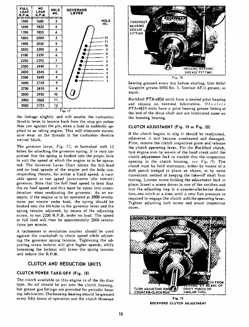
LOAD LOAD NO.R.P.M. RoP.M.
1500 1685 3 HOLENO.
1600 1825 4
1700 1855 4
1800 2000 5’ 12
1900 2055 5
2000’ 2oo 62100 2230 62200 2375 7
2300 2440 7
2400 2545 82500 2695 9
2600 2745 9
2700’ L 2810 9
2800 2935 1(~’ ~,2900 3065 13000 3175 12
Fig. 17
the linkage slightly and will enable the carburetorthrottle lever to bounce back from the stop pin ratherthan jam against the pin, when a load is suddenly ap-plied to an idling engine. This will eliminate exces-sive wear on the threads in the carburetor throttleswivel block.
The governor lever, Fig. 17, is furnished with 12holes for attaching the governor spring. It is very im-portant that the spring is hooked into the proper holeto suit the speed at which the engine is to be opera-ted. The Governor Lever Chart shows the full loadand no load speeds of the engine and the hole cor-responding thereto, for either a fixed speed, a vari*able speed or two speed (over-center idle control)governor. Note that the full load speed is less thanthe no load speed and this must be taken into consi-deration when readjusting the governor. As an ex-ample; if the engine is to be operated at 2000 revolu-tions per minute under load, the spring should behooked into the 6th hole in the governor lever and thespring tension adjusted, by means of the adjustingscrew, to run 2200 R.P.M. under no load. The speedat full load will then be approximately 2000 revolu-tions per minute.
A tachometer or revolution counter should be usedagainst the crankshaft to check speed while adjust-ing the governor spring tension. Tightening the ad-justing screw locknut will give higher speeds, whileloosening the locknut will lower the spring tensionand reduce the R.P.M.
CLUTCH AND REDUCTION UNITS
CLUTCH POWER TAKE-OFF (Fig. 18)
The clutch available on this engine is of the dry disctype. No oil should be put into the clutch housing,but grease gun fittings are provided for periodic bear-ing lubrication. The housing bearing should be greasedevery fifty hours of operation and the clutch throwout
HOUSING RINGGREASE FITTING
Fig. 18
bearing greased every day before starting. Use MobilGargoyle grease BRB No. 3, Sinclair AF-1 grease, orequal.
Rockford PTA-4856 units have a sealed pilot bearingand require no external lubrication. Obs olet ePTAo4819 units have a pilot bearing grease fitting atthe end of the drive shaft and are lubricated same asthe housing bearing.
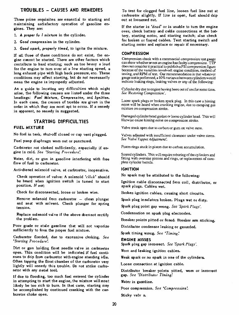
CLUTCH ADJUSTMENT (Fig. 19 or Fig. 20)
If the clutch begins to slip it should be readjusted,otherwise it will become overheated and damaged.First, remove the clutch inspection plate and releasethe clutch operating lever. For the Rockford clutch,turn engine over by means of the hand crank until theclutch adjustme.nt lock is visible thru the inspectionopening in the clutch housing, see Fig. 19. Theclutch must be held stationary, either by means of adrift punch wedged in place as shown, or by someconvenient method of keeping the take-off shaft fromturning. Loosen screw holding the adjustment lock mplace. Insert a screw driver in one of the notches andturn the adjusting ring in a counter-clockwise direc-tion, one notch at a time, until a very firm pressure isrequired to engage the clutch with the operating lever.Tighten adjusting lock screw and mount inspectioncover,
TURN ADJUSTINGCOUNTER-CLOCK WlSE
DRIFT PUNCH ORSIMILAR TOOL
FROMiS OF
Fig. 19ROCKFORD CLUTCH ADJUSTMENT
18
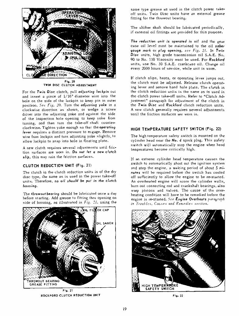
Fig. 20TWIN DISC CLUTCH ADJUSTMENT
For the Twin Disc clutch, pull adjusting [ockpin outand insert a piece of 1/16" diameter wire into thehole on the side of the lockpin to keep pin in outerposition. See Fig. 20. Turn the adjusfing yoke in aclockwise direction as shown, or wedge a screwdriver into the adjusting yoke and against the sideof the inspection hole opening to keep yoke fromturning, and then turn the take-off s;haft counter-clockwise. Tighten yoke enough so tha~: the operatinglever requires a distinct pressure to er~gage. Removewire from lockpin and turn adjusting yoke slightly, toallow lockpin to snap into hole in floating plate.
A new clutch requires several adjustments until fric-tion surfaces are worn in. Do not let a new clutchslip, this may ruin the friction surfaces.
CLUTCH REDUCTION UNIT (Fig. 21)
The clutch in the clutch reduction units is of the drydisc type, the same as is used in the power take-offunits. Therefore, no oil should be pul~ in the clutchhousing.
The throwout bearing should be lubricated once a daybefore starting. Add grease to fitting thru opening onside of housing, as illustrated in Fig.. 2], using the
ER CAP
DIL SABER
/
BEARINGGREASE FITTING
Fig. 21ROCKFORD CLUTCH REDUCTION UNIT
same type grease as used in the clutch power take-off units. Twin Disc units have an external greasefitting for the throwout bearing.
The shifter shaft should be lubricated periodically,if external oil fittings are provided for this purpose.
The reduction unit is operated in oil and the gearcase oil level must be maintained to the oil sabergauge mark or plug opening, see Fig. 21. In TwinDisc units, high grade transmission oil S.A.E. No.90 to No. 110 Viscosity must be used. For Rockfordunits, use No. 30 S.A.E. crankcase oil. Change oilevery 2000 hours of service, while unit is warm.
If clutch slips, heats, or operating lever jumps out,the clutch must be adjusted. Release clutch operat-ing lever and remove hand hole plate. The clutch inthe clutch reduction units is the same as is used inthe clutch power take-off units. Refer to "Clutch Ad-justment" paragraph for adjustment of the clutch inthe Twin Disc and Rockford clutch reduction units.A new clutch generally requires several adjustmentsuntil the friction surfaces are worn in.
HIGH TEMPERATURE SAFETY SWITCH (Fig. 22)
The high temperature safety switch is mounted on thecylinder head near the No. 4 spark plug. This safetyswitch will automatically stop the engine when headtemperatures become critically high.
If an extreme cylinder head temperature causes theswitch to automatically short out the ignition systemand stop the engine, a waiting period of about 5nutes will be required before the switch has cooledoff sufficiently to allow the engine to be re-started.An overheated engine will score the cylinder walls,burn out connecting rod and crankshaft bearings, alsowarp pistons and valves. The cause of the over-heating condition will have to be remedied before theengine is re-started. See Engine Overheats paragraphin Troa~les, Causes and Remedies section.
;AF ETY SWITCH
Fig. 22
19
TROUBLES - CAUSES AND REMEDIES
Three prime requisites are essential to starting andmaintaining satisfactory operation of gasoline en-gines. They are:
1. A proper fu I mixture in the cylinder.
Good compression in the cylinder.
3. Good spark, properly timed, to ignite the mixture.
If all three of these conditions do not exist, the en-gine cannot be started. There are other factors whichcontribute to hard starting; such as too heavy a loadfor the engine to turn over at a low starting speed, along exhaust pipe with high back pressure, etc. Theseconditions may affect starting, but do not necessarilymean the engine is improperly adjusted.
As a guide to locating any difficulties which mightarise, the following causes are listed under the threeheadings: Fuel Mixture, Compression, and Ignition.In each case, the causes of trouble are given in the
order in which they are most apt to occur. If a remedyis apparent, no remedy is suggested.
STARTING DIFFICULTIESFUEL MIXTURE
No fuel in tank, shut-off closed or cap vent plugged.
Fuel pump diaphragm worn out or punctured.
Carburetor not choked sufficiently, eapecially if en-gine is cold. See ’Starting Procedure’.
Water, dirt, or gum in gasoline interfering with freeflow of fuel to carburetor.
Anti-diesel solenoid valve, at carburetor, inoperative.
Check operation of valve: A solenoid ’click’ shouldbe heard when ignition switch is turned to startposition. If not;
Check for disconnected, loose or broken wire.
Remove solenoid from carburetor - clean plungerand seat with solvent. Check plunger for springtension.
Replace solenoid valve if the above doesnot rectifythe problem.
Poor grade or stale gasoline that will not vaporizesufficiently to form the proper fuel mixture.
Carburetor flooded, due to excessive choking. See’Starting Procedure’.
Dirt or gum holding float needle valve in carburetoropen. This condition will be indicated if fuel conti-nues to drip from carburetor with engine standing idle.Often tapping the float chamber of the carburetor verylightly will remedy this trouble. Do not strike carbu-retor with any metal tool.
If due to flooding, too much fuel entered the cylinderin attempting to start the engine, the mixture will mostlikely be too rich to burn. In that case, starting maybe accomplished by continued cranking with the car-buretor choke open.
To test for clogged fuel line, loosen fuel line nut atcarburetor slightly. If line is open, fuel should dripout at loosened nut.
If the starter is ’dead’ or is unable to turn the engineover, check battery and cable connections at the bat-tery, starting motor, and starting switch; also checkfor broken or frayed cables. Test starting switch andstarting motor and replace or repair if necessary.
COMPR ESSIONCompression check with a commercial compression test gaugecan show whether or not an engine has faulty compression. TTPdoes not consider it practical to publish a PSI compression figurebecause of the variables involved: engine condition, method oftesting, and RPM of test. Our recommendation is that whatevergauge test is performed, a 10% variance between cylinders wouldindicate leaking rings, leaking valves or any of the following:
Cylinder dry due to engine having been out of use for some time.See ’Restoring Compression’.
Loose spark plugs or broken spark plug. In this case a hissingnoise will be heard when cranking engine, due to escaping gasmixture on compression stroke.
Damaged cylinder head gasket or loose cylinder head. This willlikewise cause hissing noise on compression stroke.
Valve stuck open due to carbon or gum on valve stem.
Valves adjusted with insufficient clearance under valve stems.See "Valve Tappet Adjustment:
Piston rings stuck in piston due to carbon accumulation.
Scored cylinders. This will require reboring of the cylinders andfitting with oversize pistons and rings, or replacement of com-plete cylinder barrels.
IGNITION
No spark may be attributed to the following:
Ignition cable disconnected from coil, distributor, orspark plugs. Cables wet.
Broken ignition cables, causing short circuits.
Spark plug insulators broken. Plugs wet or dirty.
Spark plug point gap wrong. See ’Spark Plugs’.
Condensation on spark plug electrodes.
Breaker points pitted or fused. Breaker arm sticking.
Distributor condensor leaking or grounded.
Spark timing wrong. See "Timing:
ENGINE MISSESSpark plug gap incorrect. See "Spark Plugs’.
Worn and leaking ignition cables.
Weak spark or no spark in one of the cylinders.
Loose connection at ignition cable.
Distributor breaker points pitted, worn or incorrectgap. See ’Distributor Timing:
Water in gasoline.
Poor compression. See ’Compression:
Sticky valv s.
2O

ENGINE SURGES OR GALLOPS
Carburetor flooded.
Governor spring hooked into wrong hole in lever.Governor rod incorrectly adjusted. See "Governor Ad-jus trne n t ’.
ENGINE STOPS
Fuel tank empty.
Water, dirt or gum in gasoline.
Gasoline vaporized in fuel lines, due to excessiveheat around engine (Vapor Lock). See ’Stopping En-gine’.
Vapor lock in fuel lines or carburetor due to usingwinter gas (too volatile) in hot weather.
Air vent hole in fuel tank cap plugged. ’.Engine scoredor stuck due to lack of oil.
Ignition troubles. See ’Ignition’.
Wire from anti-diesel solenoid to starting switch dis-connected or damaged.
ENGINE OVERHEATS
Crankcase oil supply low. Replenisl~. immediately.
Ignition spark timed wrong. See ’Neon Lamp Timing’.
Low grade of gasoline.
Engine overloaded.
Restricted cooling air circulation.
Part of air shroud removed from engine.
Dirt between cooling fins on cylinder or he.ad.
Engine operated in confined space where cooling airis continually recirculated, consequently becomingtoo hot.
Carbon in engine.
Dirty or incorrect grade of crankcase c,il.
Restricted exhaust.
Engine operated while detonating due to low octanegasoline, or heavy load at low speed.
ENGINE KNOCKS
Poor grade of gasoline or of low octane rating. See’Fuel’.
Engine operating under heavy load at low speed.
Carbon or lead deposits in cylinder head.
Spark advanced too far. See "Neon Lamp 77ming’.
Loose or burnt out connecting rod bearing.
Engine overheated due to causes under p r e v i o u sheading.
Worn or loose piston pin.
ENGINE BACKFIRES THROUGH CARBURETOR
Water or dirt in gasoline.
Engine cold.
Poor grade of gasoline.
Sticky inlet valves.
Overheated valves.
Spark plugs too hot. See ’Spark Plugs’.
Hot carbon particles in engine.
LOW or NO OIL PRESSURE
Oil pressure gauge defective.
Oil line to gauge clogged up.
Crankcase oil supply low.
Faulty oil pump.Gears worn or broken.Cover worn.Loose cover or body.Gasket damaged.
Faulty relief valve.
Clogged or leaky oil line connections.
Strainer screen clogged up.
Oil too thin dueto dilution or too light of grade used.
Worn rod bearings.
HIGH OIL PRESSURE
Oil pressure gauge defective.
Oil too heavy.
Faulty relief valve.
Clogged pressure line.
INSTRUCTIONS FOR PROTECTING ENGINESFOR WINTER OR SHORT STORAGE PERIODS
To protect the cylinders, pistons, rings and valvesand keep them from rusting and sticking, a half andhalf mixture of kerosene and good engine oil, (thesame kind of oil as used in the crankcase of the en-gine), shonld be injected into the pipe tap openingon the intake manifold while the engine is warm andrunning at moderate speed. About a quarter of a pintis necessary, or enough so that a heavy bluish smokewill appear at the exhaust. The ignition switch shouldthen be shut off and the engine stopped. This foggingoperation will leave a coating of oil on the abovementioned parts, protecting them from the atmosphere.
Drain crankcase oil while the engine is warm, as theoil will flow more freely than when cold.
Drain fuel lines, carburetor, fuel pump and tank of allgasoline, to prevent lead and gum sediment from in-
21

terfering with future operation. Gasoline fumes fromgradual evaporation is a dangerous fire hazard.
The air cleaner should be thoroughly cleaned of alloil and accumulated dust, and the sediment removedfrom the oil cup at the bottom of the cleaner.
Tape or otherwise seal off the air cleaner or carbure-tor intake, as well as the exhaust and breather open-ings, for the duration of the storage period.
The outside of the engine, including the cooling finson the cylinders and heads, should be thoroughlycleaned of all dirt and other deposits.
All exposed unpainted metal parts should be coatedwith grease or heavy oil.
Before starting the engine after the storage period,remove crankcase drain plug so that any condensa-tion which may have collected may be drained beforenew crankcase oil is added. It is highly recommend-
ed that the crankcase bottom cover be removed andscrubbed of all sediment which may have collectedthere. When reassembling the bottom cover, a newgasket should be used.
Fill crankcase with the correct grade of oil to thefull mark on the saber. Do not use any oil heavierthan $AE No. 30. Also be sure to put oil to the properlevel in the air cleaner. (Refer to Lubrication and AirCleaner.)
It is advisable to use new spark plugs at the begin-ning of the operating interval, especially if the en-gine has given considerable service.
Refuel engine and follow the starting instructions asshown on preceding pages of this manual.
It is suggested that machines be stored inside abuilding. If this is not possible, protect the en-gine from the weather by a proper covering.
22

DISASSEMBLYOF
AND REASSEMBLYENGINE
Engine repairs should be made only by a mechanicwho has had experience in such work. When disassem-bling the engine, it is advisable to have several boxesavailable so that parts belonging to certain groupscan be kept together. Capscrews of ’various lengthsare used in the engine, therefore great care must beexercised in reassembly so the right screw will beused in the proper place.
Tighten the capscrews and nuts of the manifolds,cylinder heads, gear cover, oil pan, connecting rods,cylinder barrels, main bearing plate and the sparkplugs to the specified torque readings indicated inthe paragraphs of reassembly, relative to these parts.
While the engine is partly or fully dismantled, all ofthe parts should be thoroughly cleaned. Use all newgaskets and ’O’ rings in reassembly, and lubricateall bearing surfaces.
The following procedure is for complete disassemblyof an engine. As disassembly progresses, the ordermay be altered somewhat, as will be self-evident tothe mechanic. Reassembly of the engine should bemade in the reverse order.
TESTING REBUILT ENGINE
An engine that has been rebuilt with new connectingrod shell bearings and having cylinders rebored orreplaced, and fitted with new pistons, rings andvalves, should go through a thorough "run-in" periodbefore any load is applied to it.
The engine should be started and allowed to run forabout one-half hour at about 1200 ~o 1400 R.P.M.without load. The R.P.M. should t hen be increased toengine operating speed, still without load, for anadditional three and one-half to four hours.
The proper =running-in" of the engine will help toestablish polished bearing surfaces and proper clear-ances between the various moving parts and thusadd years of trouble free service to the life of yourengine.
ACCESSORIES
Remove clutch or clutch reduction unit if engine isequipped with either of these accessories.
AIR CLEANER can be removed as a complete unitwhen flywheel shroud is removed. Disconnect tubingand elbow connection from carburetor to air cleaner.
CONTROL PANEL can remain on :Flywheel shroud,but disconnect: ignition wires from anti-diesel sole-noid, starting solenoid, choke wire at carburetor,hose at oil pressure gauge, variable speed control,ignition wires at coil and voltage regulator (batteryterminal).
OIL FILTER is removed by tapping side of cartridgewith a mallet to break the seal. Then pierce can withscrew driver or similar pointed tool to serve as ahandle for unscr ewing filter from case. Place a panunder the filter to catch oil leakage when filter is re-moved. Refer to =Oil Filter", Page 10, for replace-meat instructions.
STARTING MOTOR is removed by disconnecting ig-nition wires at solenoid and taking out the three cap-screws holding starter to flange on gear cover. Note:The rubber Bendix cover will drop off when flywheelshroud is removed.
FLYWHEEL (Fig. 23, Fig. 24)
After the flywheel screen has been removed, drive outthe starting crank pin in the crankshaft and straightenout the bent tabs on lockwasher. By means of a 2¼"socket power wrench or 2¼" offset box wrench, asshown in Fig. 23, remove flywheel nut. Strike thehandle of the wrench a sharp blow with a soft hammerto loosen nut. Do not use an open end, monkey orpipe wrench.
The flywheel is mounted to a taper on the crankshaft.Take a firm hold on the flywheel fins, pull outwardand at the same time strike the end of the crankshaftseveral times with a babbitt hammer, see Fig. 24.The flywheel will slide off the taper of the crank-shaft. Do not use a hard hammer as it may ruin thecrankshaft and bearings. Remove Woodruff key fromcrankshaft.
In reassembly; be sure the Woodruff key is in positionon the shaft and that the keyway in the flywheel is
Fig. 23
23

Fig. 24
lined up accurately with the key. After mounting; seatflywheel on crankshaft taper by slipping a piece ofpipe over the end of the crankshaft and against thehub of the flywheel, and striking the end of the pipea sharp blow with a hammer.
FLYWHEEL SHROUD (Fig. 25)
Remove cylinder head covers by dis-engaging 3 clipsand taking out the thumb screw.
Disconnect No. 2 and No. 4 spark plug wires and hi-temperature switch wire. Slip wires thru grommet inshroud.
HEAT DEFLECTORCAP SCREW HOLES STARTER
DIX COVER
COVER CLIPS CYLINDER SHROUDCAPSCREW HOLES
FLYWHEELSHROUD
Fig. 25
;ENERATOR
ADJUSTING STRAPSLOTTED HOLES
IN GENERATOR BRACKETFOR I~ELT ALIGNMENT
Fig. 26
Take out the following capscrews: 4 from flywheelshroud to cylinder shrouds, 4 from heat deflectorsand 6 from inside flywheel shroud to gear cover. Theflywheel shroud, air cleaner and control panel assem-bly can be removed as illustrated in Fig. 25.
In reassembly; insert rubber Bendix cover betweenflywheel shroud and starter pad on gear cover.
GENERATOR m Older Models (Fig. 26)
Disconnect ignition wires from field and armatureterminals. Take out the capscrew holding the adjust-ing strap to generator. By taking out the 2 capscrewswhich hold the bracket to the engine supports, thegenerator can be removed as shown in Fig. 26.
Note that the holes in the generator bracket are slot-ted for belt alignment in reassembly.
DISTRIBUTOR AND ACCESSORY DRIVE (Fig. 27)
Disconnect ignition wire at distributor and take offdistributor cap, leaving high tension cables in place.Remove 2 capscrews holding the accessory drivehousing to the gear cover. As illustrated in Fig. 27,the distributor and accessory drive housing can bewithdrawn from the gear cover as a complete unit.
DISTRIBUTOR ACCESSORYDRIVE HOUSING
Fig. 27
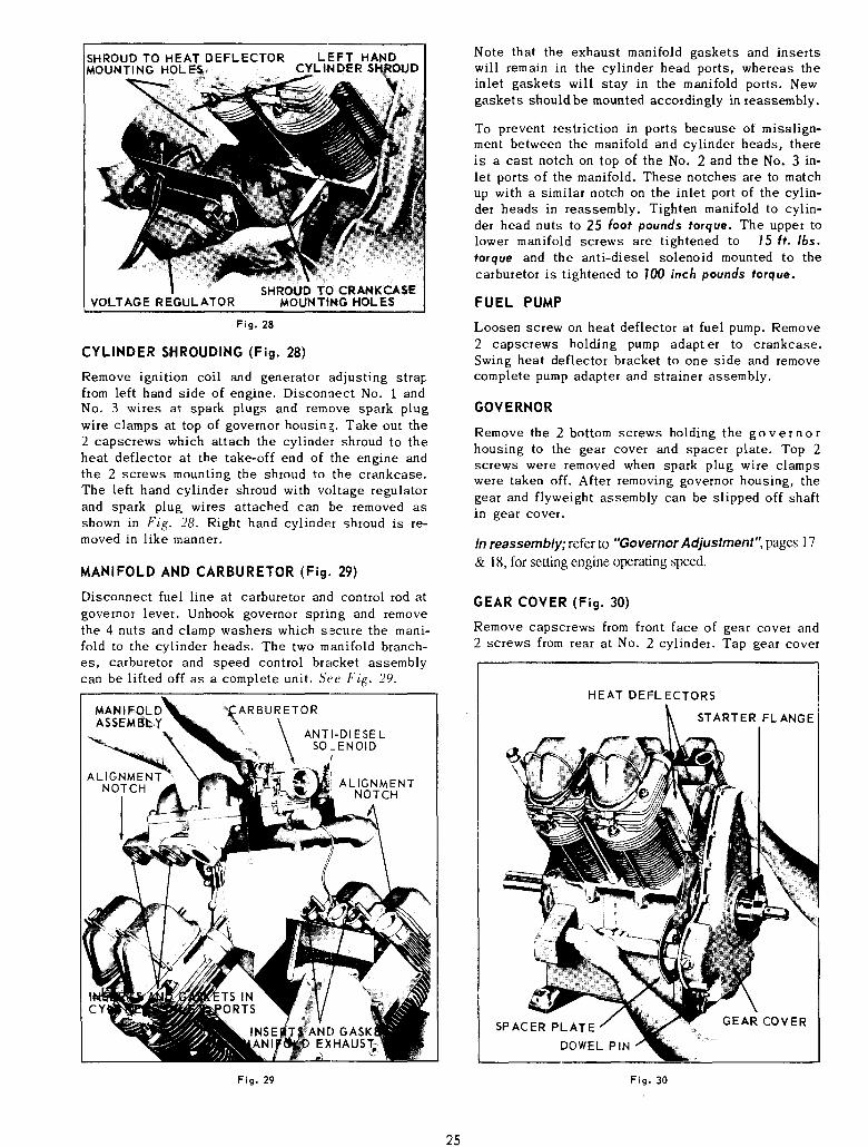
SHROUD TO HEAT DEFLECTOR LEFT HANDMOUNTING HOLES CYLINDER
VOLTAGE REGULATORSHROUD TO CRANKCASE
MOUNTING HOLES
Fig. 28
CYLINDER SHROUDING (Fig. 28)
Remove ignition coil and generator adjusting strapfrom left hand side of engine. Disconnect No. 1 andNo. 3 wires at spark plugs and remove spark plugwire clamps at top of governor housing. Take out the2 capscrews which attach the cylinder shroud to theheat deflector at the take-off end of the engine andthe 2 screws mounting the shroud to the crankcase.The left hand cylinder shroud with voltage regulatorand spark plug wires attached can be removed asshown in Fig. 28. Right hand cylinder shroud is re-moved in like manner.
MANIFOLD AND CARBURETOR (Fig, 29)
Disconnect fuel line at carburetor and control rod atgovernor lever. Unhook governor spring and removethe 4 nuts and clamp washers which secure the mani-fold to the cylinder heads. The two manifold branch-es, carburetor and speed control bracket assemblycan be lifted off as a complete unit. See Fig. 29.
~ARBUR ETORANTI-DIESEL
SOI_ENOID
ALIGNMENTNOTCH
)ORTS
Fig. 29
Note that the exhaust manifold gaskets and insertswill remain in the cylinder head ports, whereas theinlet gaskets will stay in the manifold ports. Newgaskets should be mounted accordingly in reassembly.
To prevent restriction in ports because of misalign-ment between the manifold and cylinder heads, thereis a cast notch on top of the No. 2 and the No. 3 in-let ports of the manifold. These notches are to matchup with a similar notch on the inlet port of the cylin-der heads in reassembly. Tighten manifold to cylin-der head nuts to 25 foot pounds torque. The upper tolower manifold screws are tightened to 15 It. /bs.torque and the anti-diesel solenoid mounted to thecarburetor is tightened to |00 inch pounds torque.
FUEL PUMP
Loosen screw on heat deflector at fuel pump. Remove2 capscrews holding pump adapter to crankcase.Swing heat deflector bracket to one side and removecomplete pump adapter and strainer assembly.
GOVERNOR
Remove the 2 bottom screws holding the governorhousing to the gear cover and spacer plate. Top 2screws were removed when spark plug wire clampswere taken off. After removing governor housing, thegear and flyweight assembly can be slipped off shaftin gear cover.
In reassembly; refer to "Governor Adjustment", pages 17& 18, for setting engine operating speed.
GEAR COVER (Fig. 30)
Remove capscrews from front face of gear cover and2 screws from rear at No. 2 cylinder. Tap gear cover
HEAT DEFLECTORS
STARTER FLANGE
SPACER PLATEDOWEL PIN
GEAR COVER
Fig. 30
25

CAMSHAFT THRUSTPLUNGER AND SPRING
GOVERNOR GEAR
CAMSHAFT GEAR
TIMING MARKS
CRANKSHAFTGEAR
ACCESSORYDRIVE GEAF
IDLER GEAR OIL PUMP GEAR
Fig. 31
alternately, from starter flange to accessory drivehousing opening, and remove as illustrated in Fig.30. Note that dowel pins will remain in cover. Cylin-der heat deflectors can now be removed.
In reassembly; tighten gear cover capscrews to |8foot pounds torque.
GEAR TRAIN (Fig. 31)
With the removal of gear cover and oil sling, the geartrain will be exposed as shown in Fig. 31. Removecamshaft thrust plunger and spring to prevent theirbeing lost.
Future reference can be made to Fig. 31 when assem-bling crankshaft and camshaft, as accurate locationof the timing marks is essential for proper engineoperation.
SPACER PLA"FOR ACCESSORY DF HOUSING
ALLEN HEADLOCKSCREW
SLOTTED PIPE PLUG
Fig. 32
SPACER PLATE ANGEFOR IVE HOUSING
LOCKSCREW HOLE
LOCKSCREW SEAT
Fig. 33
ENGINE SUPPORTS AND OIL PAN (Fig. 33)
Use a work bench with a clearance hole of at least2¼ inches in diameter for the engine crankshaft toextend thru, and tip the engine over to rest on themain bearing plate - or, if convenient, construct anengine fixture by making a box from 2 x 6 lumber asillustrated in Fig. 33. Make the box about 16 inchessquare x 8 inches high with a 2¼ inch clearance holein the top, and open at the bottom.
With engine tipped over on take-off end, remove en-gine supports and oil pan. In reossembly; use a newgasket underneath oil pan, mount with oil drain to-ward side opposite flange on spacer plate for acces-sory drive housing, and tighten capscrews to 18 footpounds torque.
Mount engine supports with machined flats towardflange side of spacer plate where accessory drivehousing is mounted. Use Perma-tex on capscrews forboth engine supports and oil pan. Tighten capscrewsfor engine supports to 40 foot pounds torque.
OIL PUMP (Fig. 32, Fig. 33)
Remove locknut and driver gear from shaft. If gear istoo tight to remove by hand, use a pulley; hammeringon end of shaft t o loosen gear will damage pump.
Take out slotted pipe plug from bottom of crankcase,and with a 5/32 inch Allen wrench, remove lockscrewas shown in Fig. 32. Withdraw the oil pump from in-side the crankcase, as illustrated in Fig. 33. If pumpfits too tight to remove by hand, tap front of pumphousing (not shaft), with hammer and brass rod.
In reassembly; be sure lockscrew seat in pump hous-ing lines up with lockscrew hole in crankcase.
26

SPECIAL FEATUREIndividual cylinder heads, barrels, pistons and ringscan be removed for replacement without a major en-gine disassembly, by means of a special piston sleeve.
Refer to Fig’s. 34, 36, 37 andCylinder Head, Cylinder Barrel paragraphs.
CYLINDER HEAD (Fig. 34, Fig. 35)
Remove rocker arm cover by means of a screw driverwedged under the bail wire. Take off the 4 nuts andwashers from cylinder barrel studs. Lift cylinderhead and rocker arm assembly off cylinder. The oildrain line will slip out of adapter in crankcase. Pullout push rods and rod housings. See Fig. 34.
In reassembly; place a new ’O’ ring under collar ofpush rod housing. Press collar end of tube into tap-pet hole by hand; do not drive tubes in place with ahammer. Use new ’O’ ring for push rod housing to re-cess in cylinder head. Spread a light film of greaseon cylinder head gasket so it will stick in place dur-ing reassembly. Place new ’O’ ring on oil drain tuh~,
Note: When reassembling cylinder heads on a com-
plete overhaul, ~t will be necessary to square up theinlet and exhaust port flanges with those of the mani-fold. See Fig. 35. Place a parallel steel bar acrossthe ports and tap the heads lightly with a rubber mal-let to rotate them until they are square. Turn cylinderhead nuts to a snug fit and re-check alignment.Torque cylinder head nuts alternately and in 3 steps.First 10, then 20, and finally 30 {oot pounds torque.
ROCKER ARMASSEMBLY
CYLINDER
PUSH ROD PUSH ROD
Fig° 34
PARALLEl_ STEEL BAR
Rocker arm assembly can be left bolted to the cylin-der head, unless head or rocker arms need replacing.
CYLINDER BARREL (Fig. 36, Fig. 37)
Turn crankshaft over until piston, in the cylinderbarrel that is to be replaced, is at the top of itsstroke. Remove; top cylinder stud (flanged) on ModelV-461D, or hold down clip as used on Model V-465D.The remaining studs can be disassembled after cylin-der is taken off.
In reassembly; place a new gasket at bottom of cylin-der barrel. It will be necessary to compress the pistonrings in order to slip the cylinder over the piston, asshown in Fig. ,37. A piston sleeve can be made fromthe lower portion of a scrap cylinder. The sleeve is2¼ inches long with a 7/8 inch wide slot. The insidediameter is tapered from the middle to the bottom;
3.750" to 4.000 for V-465D3.500" to 3.750 for V-461D, V-460D
CYLINDER BARREL
CONNECTING
Fig. 36
CYLINDER BARREL SLOT FOR CLEARINGCONNECTING ROD
RING OPENINGIN LINE WITH SLOT
Fig. 35 Fig. 37
27
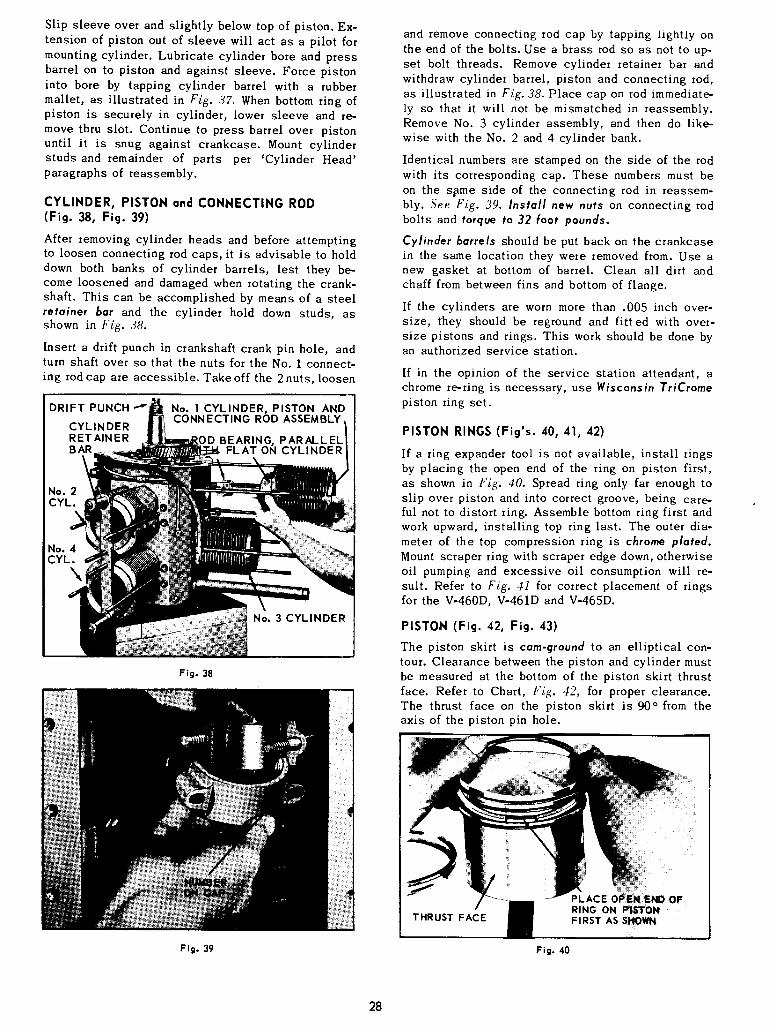
Slip sleeve over and slightly below top of piston. Ex-tension of piston out of sleeve will act as a pilot formounting cylinder. Lubricate cylinder bore and pressbarrel on to piston and against sleeve. Force pistoninto bore by tapping cylinder barrel with a rubbermallet, as illustrated in Fig. 37. When bottom ring ofpiston is securely in cylinder, lower sleeve and re-move thru slot. Continue to press barrel over pistonuntil it is snug against crankcase. Mount cylinderstuds and remainder of parts per ’Cylinder Head’paragraphs of reassembly.
CYLINDER, PISTON and CONNECTING ROD(Fig. 38, Fig. 39)
After removing cylinder heads and before attemptingto loosen connecting rod caps, it is advisable to holddown both banks of cylinder barrels, lest they be-come loosened and damaged when rotating the crank-shaft. This can be accomplished by means of a steelretainer bar and the cylinder hold down studs, asshown in Fig. 38.
Insert a drift punch in crankshaft crank pin hole, andturn shaft over so that the nuts for the No. 1 connect-ing rod cap are accessible. Take off the 2 nuts, loosen
DRIFT PUNCH ""
CYLINDERRETAINER
No. 1 CYLINDER, PISTON ANDCONNECTING ROD ASSEMBLY,
OD BEARING, PARALLELFLAT ON CYLINDER
Fig. 38
and remove connecting rod cap by tapping hghtly onthe end of the bolts. Use a brass rod so as not to up-set bolt threads. Remove cylinder retainer bar andwithdraw cylinder barrel, piston and connecting rod,as illustrated in Fig. 38. Place cap on rod immediate-ly so that it will not be mismatched in reassembly.Remove No. 3 cylinder assembly, and then do like-wise with the No. 2 and 4 cylinder bank.
Identical numbers are stamped on the side of the rodwith its corresponding cap. These numbers must beon the s~me side of the connecting rod in reassem-bly. See Fig. 39. Install new nuts on connecting rodbolts and torque to 32 foot pounds.
Cylinder barrels should be put back on the crankcasein the same location they were removed from. Use anew gasket at bottom of barrel. Clean all dirt andchaff from between fins and bottom of flange.
If the cylinders are worn more than .005 inch over-size, they should be reground and fitted with over-size pistons and rings. This work should be done byan authorized service station.
If in the opinion of the service station attendant, achrome re-ring is necessary, use Wisconsin TriCromepiston ring set.
PISTON RINGS (Fig’s. 40, 41, 42)
If a ring expander tool is not available, install ringsby placing the open end of the ring on piston first,as shown in Fig. 40. Spread ring only far enough toslip over piston and into correct groove, being care-ful not to distort ring. Assemble bottom ring first andwork upward, installing top ring last. The outer dia-meter of the top compression ring is chrome plated.Mount scraper ring with scraper edge down, otherwiseoil pumping and excessive oil consumption will re-sult. Refer to Fig. 41 for correct placement of ringsfor the V-460D, V-461D and V-465D.
PISTON (Fig. 42, Fig. 43)
The piston skirt is cam-ground to an elliptical con-tour. Clearance between the piston and cylinder mustbe measured at the bottom of the piston skirt thrustface. Refer to Chart, Fig. 42, for proper clearance.The thrust face on the piston skirt is 90° from theaxis of the piston pin hole.
Fig. 39
THRUST FACE
P LAC E O~EN ENDOFRING ON PISTON
Fig. 40
28

V-460D, V-461D V-465DPISTON CHROME FACED PISTON
COMPRESSION
RING
RING WITEXPANDER
Fig. 41
Models ModelCYLINDER V-460D, V-461D V-465D
BORE 3.498 to 3.499" :3.748 to 3.749"
PISTON TO CYLINDERAT PISTON SKIRT THRUST FACES ,0025 to .003"
PISTON RING COMPRESSED GAP .008 to .024=
PISTON RINGS - SIDE CLEARANCEIN GROOVES ,002 to ,004"
CONNECTING ROD TO CRANKPIN - SIDE CLEARANCE .008 to
CONNECTING ROD SHELL BEAR-ING TO CRANK PIN .0005 to .0018"
PISTON PIN TOCONNECTING ROD BUSHING .0005 to .0011
.0000 to .0008"PISTON PIN TO PISTON tight
CENTER MAIN SHELL BEARINGTO CRANKSHAFT JOURNAL .0013 to .0038"
STANDARD
~ 1.0721.062 m
-- 2.3020 DIA.
CRANK PIN DIMENSIONS
.̄.e,.-.--. 1 355"350 WIDTH1.
__ 2.1238 DIA. GRIND2.1233 ALL ,.’RANK PINS
GRIND2.3025 CENTER MAIN ’SHELL’ BEARING
I_ 2.3000 FOR OBSOLETE ’ROLLER’ BEARING2.3005
Fig. 42, PISTON, RING AND ROD CLEARANCECRANKPIN AND CENTER BEARING DIMENSIONS
Piston and connecting rod is sub-assembled to thecylinder barrel and the complete unit is mounted tothe crankcase. Lubricate the piston assembly andcylinder walls with No. 30 S.A.E. oil, and stagger
the ring gaps 90° around the piston. Use a standard
RING COMPRESSOR
PISTON AND..... ~ CONNECTING ROD
FLAT ONCYLINDER BARREL
Fig. 43
automotive type ring compressor, and insert rod endinto cylinder from cylinder head end. Note: Rod bear-ing should be parallel to flats at base of cylinderbarrel for correct assembly to crankshaft, see Fig.38. Gently tap piston into cylinder and to bottom of
bore. Use the wooden handle end of hammer, as shownin Fig. 43.
VALVES (Fig. 44)
Replace valves that are burned or pitted. A leakyvalve can usually be determined by a "hissing’ noise
in the exhaust or intake manifold when cranking theengine slowly by hand.
The exhaust valves are furnished with positive type rota-
tors. Refer to Illustrated Parts Catalog for mounting. Thevalve rotates slightly each time it opens, and therebyprevents the build up of foreign deposits on the valve faceand stem. Clean and inspect operation of rotators --replace if faulty.
Volve grinding should be done by an authorized ser-vice dealer, since he has the necessary equipmentand experience to do a good job. To remove valves;
use a standard automotive valve lifter as illustratedin Fig, 44, and remove spring seat locks. Releasevalve lifter and take out valve, spring and exhaust
rotator or spring seat.
The valve face is ground at 45 o to the vertical center
line of the valve stem and the valve seat insertshould also be ground at a 45° angle. After grinding,
valves and inserts should be lapped with a suitable
lapping compound or they will leak due to improperseating, within the first few hours of operation. Whilelapping, occasionally lift the valves and reset them
29

in a different position to insure a uniform seat entire-ly around the valves. After valves have been lappedin evenly, remove and wash both valves and headthoroughly with kerosene and re-assemble.
VALVE GUIDES. The valve stem has a clearance of.002" to .004~ in the guide. When clearance becomes.006~, the guide should be driven out and a new guidepressed in place. Allow 1/32" to 1/64~ clearance be-tween valve guide boss and bottom of valve guideshoulder. Check guide for .3440/.3445" I.D. afterpressing in place. Ream if necessary.
VALVE SEAT INSERTS are not replaceable, due tomethod of installing. If seat inserts become worn andground down to the extent that the seats are widerthan the valve face, replace cylinder head.
ROCKER ARM ASSEMBLY (Fig. 44)
Very little wear will occur to the rocker arms as longas they are adequately lubricated. If replacement isnecessary, remove the complete rocker arm bracketassembly, Fig. 44, from cylinder head. Take out shaftsetscrew from bottom of bracket with a 1/8" Allen
ROCKER ARM VALVE LIFTERASSEMBLY
/
SPRING SEAT LOCKS
Fig. 44
CAMSHAFT ASSEMBLY
VALVE TAPPETS(Pull Outward)
Fig. 45
wrench, and tap shaft out toward setscrew end ofbracket, using a brass rod. NOTE: Beginning withserial # 5634850, setscrew is secured in place with# 271 Loctite in place of staking. To loosen setscrewfor removal, apply heat (400 o F) to setscrew.
In reassembly; flat surface on shaft fo~ setscrew mustline up with tapped hole in bracket. Apply # 271 Loctiteto setscrew threads and securely tighten in place.Lubricate shaft so that rocker arm bearings will notoperate dry when starting engine.
CAMSHAFT (Fig. 45, Fig. 46)
Pull tappets outward to clear lobes for camshaft re-moval. Withdraw tappets from inside crankcase. In re-assembly, clean, lubricate tappets and insert thrustplunger and spring into end of camshaft, See Fig. 46.
The camshaft gear has offset mounting holes to pro-vide accurate assembly for valve timing. The gear canonly be put on the correct way for matching up the tim-ing mark with that of the crankshaft. See Fig. 46.
;EAR
Fig. 46
CENTER MAIN BEARING (Fig. 47, Fig. 48) V-465D
Note: Beginning with engine serial No. 4904657, ashell type center main bearing replaces the split rol-ler bearing. The bearing and hanger assemblies arenot interchangeable for service replacement unlessthe complete crankshaft assembly is changed and thecrankcase modified.
The following instructions apply to the current pro-duction engines with shell center main.bearing. Referto Page 32 for overhaul procedures relative to the nowobsolete roller type center main bearing and crank-shaft oil collet.
Caution: Do not attempt to remove crankshaft from en-gine without first removing center bearing hanger.
With reference to Fig. 47, disconnect oil pressure lineat center bearing hanger and at oil header behind fil-ter, by using a 1/2 inch hex tubing nut wrench. Re-move hanger to case screws and washers. Then loosenand back out cap to hanger screws about 1/2 inch.Tap screw heads lightly and alternately with a ham-mer to break cap away from hanger body.
3O

Tu~ Fittin Sli~To
Fig. 47
LUGS
Fig. 48
Do not pry cap and body apart. Sepztrate and removehanger and cap with shell bearing from cra~nkcase.
Check bearing and crankshaft journal for visible wear--see Clearance Chart, Fig. 42. If clearance approaches .005inch, replace shell bearing with suitable undersize.
In reassembly: Clean thoroughly and apply a film of oilto the bearing surfaces. Mount center main bearing aftercrankshaft is assembled to crankcase and ~’ndplay is set.
Dowel pins in cap are off-center so theft when hanger ismounted to cap, the locating lug on both bearing halves, willbe on the same side. See Fig. 48. Assemble hanger so that 45°
oil line elbow is facing toward oil header side of case asillustrated in Fig. 47.
Draw cap to hanger screws finger tight until the twodowels are just entering holes. With a hand wrench, alter-nately turn each screw 1/2 to 3/4 turns to evenly pull cap tightto hanger body. Torque screws 32 to 35foot pounds.
Secure bearing hanger to crankcase after crankshaft endplay is set. Install capscrews and washers.The tighteningtorque of the two bolts which fasten the center main bearingassembly to the crankcase of the V465D has been increased to74-76 LB-FT. Engines built after SN 6279801 will have thegreater torque applied. This change takes advantage of thegreater available strength of the grade 8 socket headcapscrews PN XB120.
For service, engines after SN 6089641 can use the newtorque specification. Also, engines built prior to that can usethe newer style grade 8 capscrew (PN XB 120, 7/16-14 x 2 1/2socket head) and can then also use the new higher torque
specifications. Note: Older engines were fitted withXD130 7/16-14 x 2 114" hex head grade 5 capscrew whichwere torqued to 60 foot pounds.
Be sure oil fitting passages are clean. Connect oil linefrom header to bearing hanger.
MAIN BEARING PLATE and CRANKSHAFT (Fig. 49)
Remove main bearing plate, gaskets and shims from take-offend of engine. Slip a length of pipe over the gear end of thecrankshaft and with the assistance of another person, withdrawthe shaft thru the main bearing plate opening, as illustratedinFig. 49.Removal of crankshaft with center bearing hanger assembled toit applies only to the obsolete split roller bearing. Caution: It willbe necessary to rotate the crankshaft so that counterweightsclear the center main bearing hanger lugs in crankcase.
In reassembly: Holes for the main bearing plate are off-set for correct mounting. Assemble main bearing plate, gas-kets and shims, and torque capscrews to 32 foot pounds.Check end play and add or remove gaskets to give thenecessary .002 to .005 inch movement, with engine cold.
IDLER GEAR AND SHAFT (Fig. 49, Fig. 52)
A tapped hole in the side of the crankcase contains 2 setscrewsfor locking idler shaft in place. See Fig. 49. Remove screws with a
Center main bearinghanger - Applicableto obsolete split ~ Iiroller bearing only.
,’ ~’i’--~jI IDLER GEARCOUNTERWEIGHT / 2 SETSCREWS
CLEARANCE SLOT FOR IDLER SHAFT
F~g. 49
5/32" Allen wrench. Disassemble shaft and gear from case bymeans of the 3/8"-16 tapped puller hole in end of idler shaft.
In reassembly; be sure oil groove in shaft is facing up.Drive shaft into crankcase with soft metal hammer and main-tain a .003 to .004 inch clearance between idler gear andshoulder of shaft, see Fig. 52. Lock shaft in place withthe 2 Allen set screws.
OIL PRESSURE RELIEF VALVE (Fig. 3, Fig. 50)
If it becomes necessary to remove the oil pressure reliefvalve, illustrated in Fig. 50, either for cleaning or replacement;fin-st unscrew hex adapter and remove expansion plug fromadapter. With a 3/16 inch Allen wrench, remove outer adjustmentlockscrew, see Fig. 3. Insert a 1/4 inch rod into the cross hole invalve body and turn counter-clockwise for removal. Do not usea pipe wrench or pliers to remove valve body.
In reassembly; use new ’O’ ring in valve body andapply sealer to threads of hex adapter. Assemble ex-
31

TUBING NUT
MOUNTING SCREWOIL PRESSURE
REDUCING VALVE
Gear oil culler -for engines withobsolete ~litroller bearing.
OIL PRESSURERELIEF VALVE(HEX ADAPTER)
EXPANSION PLUG
OIL COUPLINGTO COLLET
COUPLtNG ADAPTER
Fig. 51
CRANK SHAFTOIL COLL ET
Fig. 50
pansion plug after adjusting pressure as per "Oil Pressureand Adiustraent", pages 10 & 11.
OIL PRESSURE REDUCING VALVE (Fig. 50)
To replace the oil pressure reducing valve, loosen the4 oil line nuts at the valve and at the fittings on topand side of crankcase. Remove valve mounting cap-screw and lift valve away from crankcase. The oillines will become unseated without being deformed.
In reassembly; hold valve in proper location but donot mount. Place oil lines in position and engagetubing nuts 2 to 3 turns. Secure valve in place withcapscrew and then tighten tubing nuts.
ASSEMBLY and DISASSEMBLY PROCEDUREwith obsolete
ROLLER type CENTER MAIN BEARING(Engines previous to serial No. 4904657)
With reference to Fig. 51, remove oil coupling fromcrankshaft oil culler. Take out the adapter mountingscrew and slip oil coupling out of culler. In reassem-bly; use new ’O’ ring seals at both ends of the coupl-ing and on the shoulder extending into the crankcase.Lubricate ’O’ rings for ease in assembly.
Remove the center main bearing hanger to crankcasemounting screws and spacers. Tip case back on en-gine supports and remove main beating plate, gasketsand shims. Slip a length of pipe over the gear end ofthe crankshaft and with the assistance of another per-son, withdraw crankshaft with center bearing thru themain bearing plate opening, as illustrated in Fig. 49.
Fig. 52
Caution: It will be necessary to rotate the crank.shaft so that counterweights clear the lugs in thecrankcase for the center main bearing, and thelugs on the center bearinghanger will have to lineup with the clearance slots in the crankcase face.
In reassembly; rotate crankshaft oil collet so thatslot engages with tab on bearing retainer plate, asillustrated in F~g. 52. Mount main bearing plate, gas-kets and shims, and torque capscrews to 32 footpounds. Check end play and add or remove gasketsto give the necessary .002 to .004 inch movement.
Center main bearing (roller type) can be disassembledin the following manner: Loosen and back out bear-ing hanger capscrews approximately 1/2 inch. ’Tapcapsctew heads lightly and alternately with a hammer,as illustrated in Fig. $3, to break cap away fromhanger body. Do not pry cap and body apart. Removecapscrews and separate hanger and cap from bearing.Take off retaining ring from outer bearing race and re-move bearing halves and rollers from crankshaft.
In .reassembly; coat inside of bearing halves with alow melting point grease or petroleum jelly. Do notuse a standard lubricating grease. With reference toFig. 54, press 16 rollers into the grease of each ofthe bearing halves; assemble to crankshaft and clip
32

TAP CAPSCREWS CENTER BEARINGALT E RN AT ELY
HANGER CAP
Secure bearing hanger to crankcase after crankshaftend play is adjusted. Note: Beginning with engineserial No. 4052826, the capscrews for mounting thebearing hanger to crankcase were lengthened to 3inches, and a spacer added under the screw heads,see Fig. 56. Thus all 4 screws for the center mainbearing hanger assembly are the same, minimizingthe possibility of improper assembly. Install hangercapscrews, with spacers, finger tight and positionbearing hanger so that there is a minimum of .040inch clearance between the sides of the bearing han-ger and crankshaft cheeks. Tighten hanger to crank-case capscrews, 60 foot pounds torque.
Fi 9. 53
LOW MELTING POINT GREASE
SPLIT BEARING(FRACTURED)
BEARING ROLLERS RETAINING RING GROOVE
Fig. 54
together with retaining ring. The ring must overlapboth mating edges of the bearing. Insert shouldereddowel pin into either hole of the bearing race andplace the hanger body against the bearing so thedowel slips into the dowel pin hole, see Fig. 55.Hold hanger body against bearing, place cap in posi-tion and draw the capscrews finger tight until the 2dowels are just entering holes. With a hand wrench,alternately turn each screw 1~ to ¾ turns to evenlydraw cap tight to hanger body. Torque capscrews to40 foot pounds, alternately in 3 stages; 15, 30 and40 ft/lbs. A few squirts of oil in the hanger cap oilhole will help to dissolve the bearing grease.
----CENTER MAINBEARING HANGER
_JCRANKCASEHANGER BOSS
~ ~FINGER TIGHTEN, HANGER TO
i I CRANKCASE CAPSCREWS, FOR~,. .~.~_ SETTING CLEARANCE/--
"~--MINIMU. CLEARANCE 040" BOTHSIDES. CHECK WITH 040" SHIMS.
Fig. 56BEARING HANGER CLEARANCE
(For obsolete center main roller bearing)
DOWEL PIN HOLEDOWEL PIN
HANGER BODY
RETAINING RING
CENTER BEARING
Fig. 55
33

YB-85A ALTERNATORREPLACED YB-69 BEGINNING WITH ENGINE S/N 6070163
WI$CON~N Engine Model V-465D
SERVICE INSTRUCTIONS
SPECIFICA TI ONS
VOLTS - 12 VENTILATED - Yes RATED OUTPUT - 37 Amperes
BRUSHES - 2 CONTROL - Voltage Regulator ROTATION - Clockwise at drive end
LUBRICATION - Bearings are pre-lubricated. No additional lubrication necessary.
P R ECAU TION S:Observe proper polarity when installing battery; negativebattery terminal must be grounded. Reverse polarity willdestroy the rectifier diodes in alternator.
As a precautionary measure, disconnect ground batteryterminal when charging battery in vehicle. Connectingcharger in reverse will destroy, the rectifier diodes in thealternator.
Do Not, under any circumstances, short the field terminalof the alternator to ground, as permanent damage to theregulator may occur.
Do Not, remove the alternator from the vehicle without firstdisconnecting the grounded battery cable.
Do Not, operate engine with battery disconnected, or dis-connect the alternator output lead while the alternator isoperating, as damping effect of the battery will be lost.The voltage will rise to an extreme value and permanentdamage to the regulator may occur.
Do Not, disconnect the voltage regulator while the alterna-tor is operating, because the large voltage transient thatoccurs when disconnection takes place may damage theregulator.
Caution: Output wires from Alternator to Ammeter, and fromAmmeter to battery terminal on starting soleno{d must beof sufficient size for charging 37 omps. Use No. 10 ga.cstranded wire, or larger.
BATTERY AND CABLESFURNISHED BY CUSTOMER
10 GAGE MINIMUM(THIS WIRE OMITTED WHENAMMETER IS SHIPPED LOOSEOR SUPPLIED BY CUSTOMER)
DISCHARGE~ CHARGE
AMMETER
ANTbDIESELINGSOLENOID
IGNITION/STARTINGSWITCH
OIL PRESSURESWITCH
(WHEN SPECIFIED)
CARBURETOR
GAUGE MINIMU~
POS. (+OL~TPU~)
TERMINALALTERNATOR
IGNITIONCOIL
NO. 2 PLUG
RED WIRE
BLACK WIRE
HI-TEMPERATURESAFTETY SWITCH
STARTER
REGULATOR
EXCITATION LEAD
NO. 4 PLUG
NO. 3 PLUG
DISTRIBUTOR(S.S.I.)
34

CARBURETORSERVICE INSTRUCTIONS
L.57, L.77Series
DESCRIPTIONThe Zenith 87-Series is a horizontal carburetor with a con-centric fuel bowl. It is a ’~balanced ’~ carburetor, becauseall air for fuel chamber and metering well ventilation andidling must come through the air cleaner. Air cleanerrestrictions have a minimum influence on the fuel-air ratiowhen a carburetor is thus ~balanced".
The mai.n jet and discharge jet are centrally located. Themetering well which completely surrounds the dischargejet is in the center of the fuel bowl assembly. This con-struction permits extremely high angle operation in anydirection.
The venturi, which is part of the throttle body casting,measures the volume of air that passes through the car-buretor. In selecting the venturi size, t he smallest sizethat will permit full power development should be used.
PITOT TUBE BOWL VENTPASSAGE
FUELVALVE
SEAT
FUELVALVE
NEEDLE
FUEL LOATINLET
Fig. 1 FUEL SUPPLY SYSTEM
OPERATIONFUEL SUPPLY SYSTEM (Fig. ])
Fuel under normal pressure entering the float chamberthrough the fuel valve seat is controlled by the twin floatwhich, moving on its axle, closes the needle valve whenthe fuel reaches the proper level in the bowl.
IDLE SYSTEM (Fig. 2)
At idling speeds the throttle plate is almost closed, thus avery high suction exists at the edge of the throttle platewhere the idle discharge holes are located. All fuel foridling and part throttle operation is supplied through the
IDLE AIR IDLE AIR ~
BLE~x~ PASSAGE~ THROTTLE
IDLE DISCHARGE
.... - ~:~:~______________~__~[~e’~~_//_~ ID[E ADJUSTINGMETERING ~ 1-~t111~ ~.~c NEEDLE
WELL ~ ,~A~LI-I~ ~-IDLE.JET
~ ~:~;U~IL~.~ IDLE FUEL
~ ----- PICKUP PASSAGE
~ MAIN JET
Fig. 2 IDLE SYSTEM
main jet. Fuel from the float chamber flows through themain jet into the metering well. Fuel for idling is drawnfrom this well through the calibration, or metering orifice,in the center of the idling jet. As the fuel reaches theidling channel it is mixed with air which is admittedthrough a calibrated orifice in the channel from the insideof the air intake to form an emulsion. This emulsion isdischarged into the an" stream, to form the idling mixture,through two holes one of which is controlled by the idleadjusting needle. Turning the adjusting needle counter-clockwise (out) permits more of the emulsion to reach theair stream and make the idling mixture richer while turningthe needle in (clockwise) cuts off the amount of the emul-sion reaching the air stream and makes the mixture leaner.
HIGH .SPEED SYSTEM (Fig. 3)
As the throttle is opened, the suction on the idling systemdiminishes, but the increased volume of air entering theengine through the venturi creates sufficient vacuum(suction) on the discharge jet to draw an emulsion of fueland air from the metering well which receives its fuel fromthe main jet and its air from the well vent. The flowcharacteristics of the discharge jet are influenced by thesize, location, and number of holes in the sides of thatpart of the jet which is in the metering well, as well as by
WELL VENT \~,~
MA, N%
Fig. 3 HIGH SPEED SYSTEM
the sizes of the discharge jet orifice, the size of the maiujet, and the size of the well vent. The well vent is locatedin the air intake and permits air to enter the top of themetering well around the outside of the discharge jet. Theflow of fuel through the main jet is controlled by the sizeof main jet opening.
CHOKE SYSTEM (Fig. 4, Page 37)Starting a cold engine requires a much richer mixture offuel and air. Moving the choke lever to close the chokeplate restricts the air entering the carburetor (except at thepitot tube, Fig. 1, to the bowl vent) and increases thesuction on the idling system which makes the mixturericher.
STARTING THE ENGINE
Before cranking the engine, the carburetor throttle shouldbe opened a little to expose both idle discharge holes tosuction. The choke should be fully closed until the enginestarts, then opened a little to prevent stalling from beingover-ch’oked, then when the engine is fully warmed up thechoke can be returned to wide open position and thethrottle closed to the idling position.
ADJUSTMENTS
Adjust the throttle stop screw to obtain the desired idlingspeed by turning screw in (clockwise) to increase speedand out (counter-clockwise) to decrease engine speed.
35

ZENITH MODEL 87A8CARBURETOR
L-57, L-77Series
36
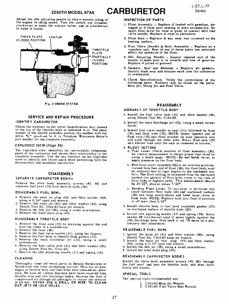
ZENITH MODEL 87A8
Adjust the idle adjusting needle to obtain smooth idling ofthe engine at idling speed. Turn the needle out (counter-clockwise) to make the mixture richer, and in (clockwise)to make it leaner.
CHOKE PLATE VENTURI(CLOSED POSITION)
THROTTLEPLATE
LYCLOSEDPOSITION)
L-57, L-77
CARBURETOR Series
INSPECTION OF PARTS
1. Float Assembly -- Replace if loaded with gasoline, da-maged or if float axle bearing is worn excessively. In-spect float lever for wear at point of contact with fuelvalve needle. Replace if wear is excessive.
2. Float Axle -- Replace if any wear has occurred on thebearing surface.
3. Fuel Valve (Needle & Seat) Assembly -- Replace as complete unit. Wear of any of these parts can seriouslyaffect the operation of the float.
4. Idle Adjusting Needle- Inspect tapered end of theneedle to make sure it is smooth and free of grooves.Replace if pitted or grooved.
S. Gaskets, Seal and Retainer - Replace all gaskets,throttle shaft seal and retainer each time the carburetoris overhauled.
6. Check Specifications. Verify the correctness of thefollowing parts. Numbers w/ll be found on the parts.Main .Jet, Idling ~et and Fuel Valve.
Fig. 4 CHOKE SYSTEM
SERVICE AND REPAIR PROCEDUREIDENTIFY CARBURETOR
CheGk the numbers on the metal identification disc pinnedto th~ top of the throttle body or indented in it. The plainnumber is the Zenith assembly number, the number with theletter "L" pre-fixed to it is Teledyne Wiscunsin Motor’spart number for the complete assembly.
EXPLODED VIEW (Page 36)The exploded view identifies the serviceable componentparts of the carburetor and shows their relationship to thecomplete assembly. Use the key numbers on the explodedview to identify and locate parts when performing both thedisassembly and assembly operations.
DISASSEMBLYSEPARATE CARBURETOR BODIES
Remove the three bowl assembly screws (145, 46) andseparate fuel bowl (39) from throttle body (26).
DISASSEMBLE FUEL BOWL
1. Remove the main jet plug (43) and fibre washer (42),using a 9/16" open end wrench.
2. Remove the main jet (41) and fibre washer (40), usingZenith Tool No. C161-83 main jet wrench.
3. Remove the Idle Jet (38), using a small screwdriver.4. Remove the bowl drain plug (44).
DISASSEMBLE THROTTLE BODY
1. Remove the float axle (35) by pressing against the endwith the blade of a screwdriver.
2. Remove the float (36).3. Remove the fuel valve needle (31), using the fingers.4. Remove the fuel bowl to throttle body gasket (37).5. Remove the main discharge jet (32), using a small
screwdriver.6. Remove the fuel valve seat (31) and fibre washer (30),
using Zenith Tool No. C161-85.7. Remove the idle adjusting needle (17) and spring (18).
CLEANING
Thoroughly clean all metal parts in Bendix Metalclene orSpeedclene and rinse in cleaning solvent. Blowout all pas-sages in throttle body and fuel bowl with reduced air pres-sure. Be sure all carbon deposits have been removed fromthrottle bore and idle discharge holes. Reverse the flow ofcompressed air through all passages to insure the removalof all dirt. NEVER USE A DRILL OR WIRE TO CLEANOUT JETS OR IDLE HOLES.
REASSEMBLYASSEMBLY OF THROTTLE BODY
I. Install the fuel valve seat (31) and fibre washer (30),using Zenith Tool No. C161o85.
2. Install the main discharge jet (32), using a small screw-driver.
3. Install fuel valve needle in seat (31), followed by float(36) and float axle (35). NOTE: Insert tapered end offloat axle (35) into float bracket on side opposite slotand push through the other side. Press float axle (35)into slotted side until the axle is centered in bracket.
4. FLOAT SETTINGa. Fuel Level. Check position of float assembly (36),
for correct measurement to obtain proper fuel level byusing a depth gage. NOTE: Do not bend, ~wist, orapply pressure on the float body.
b. With bowl cover assembly (26)in an inverted position,viewed from free end of float (36), the float body mustbe centered and at right angles to the machined sur-face. The float setting is measured from the machinedsurface (no gasket) of float bowl cover to top side float body at highest point. This measurement shouldbe 31/32=, plus or minus 1/32".
c. Bending Float Lever. To increase or decrease dis-tance between float body (36)and machined surface(26) use long nosed pliers and bend lever close float body. NOTE: Replace with new float if positionis off more than 1/16".
5. Install throttle body to fuel bowl assembly gasket (37)on machined surface of throttle body (26).
6. Install idle adjusting needle (17) and spring (18). Screwneedle IN (clockwise) until it seats lightly against theidle discharge hole, then back it out |~ turns as a pre-liminary idle adjustment.
REASSEMBLE FUEL BOWL
i. Install the main jet (41) and fibre washer (40), usingZenith Tool No. C161-83 main jet wrench.
2. Install the main jet hex plug (43) and fibre washer(42), using a 9/16~ open end wrench.
3. Install the idle jet (38), using a small screwdriver.4. Install the bowl drain plug (44).
REASSEMBLE CARBURETOR BODIES
Install the three bowl assembly screws (45, 46) throughthe fuel bowl and into the throttle body and draw downfirmly and evenly.
SPECIAL TOOLSThe special tools recommended are:
1. C161-83 Main Jet Wrench.2. C161o85 Fuel Valve Seat Wrench.
37

Magnet Service Instrucli ns
WISCONSIN No. Y-128-$1 - FAIRBANKS-MORSE Type FM-X4B7DFor Engine Models V-461D and V-465D
Yo128 Series
GENERAL DESCRIPTION
Fairbanks-Morse Type FM-X4B7D Magneto is de-signed and engineered to provide quick easy startingand maximum dependability of operation with minimumservice. The compact alnico magnetic rotor assuresan intensely hot spark under most operating conditions.
SERVICE PROCEDURE
The first step in magneto field servicing is to exa-mine the magneto for corroded high tension towers,broken wires, or high tension wires not pushed farenough into the magneto tower to make good contact.
Then test the ignition spark while the engine isbeing cranked. Hold the ignition wire 1/4 in. awayfrom the engine block. If a strong spark is observed,the magneto is not the cause of the engine malfunc-tion. If no spark is seen, proceed with servicing themagneto.
SERVICING BREAKER POINTS
Remove the end cap cover, distributor rotor andthe end cap. Then inspect the breaker points for pit-ting, oxidation and shorting. If points are worn orshorted, they should be replaced.
To remove the point set, take out the breaker armterminal screw releasing the breaker arm spring, coillead and condenser lead. Remove the fulcrum pin snapring and slide the breaker arm off the fulcrum pin.Remove the contact support locking screws and lift offthe contact support.
The installation of new points is the reverse ofthe removal. After the points have been installed,they should be adjusted to the correct clearance of0.015 inch at high point of cam. Be sure the pointsare clean and bright before adjusting them. Insert ascrewdriver in the slot of the support bracket and pi-vot it between the two small bosses on the bearingsupport until the desired clearance is obtained. Thenclean the points again before sealing the magneto.
FIELD SERVICE NOT RECOMMENDED
The cam wick, if dry or hard, should be replacedwith a new factory impregnated wick. Other than thisthe Type FM-X4B7D Magneto does not require fieldlubrication. No attempt should be made to oil or greasethe magneto bearings. The magneto lubricant should
be replaced only during the overhaul of the magnetoby a Fairbanks-Morse authorized service station usingrecommended lubricant and factory engineered parts.
Coil and condenser replacement while simple arenot recommended unless adequate test equipment isavailable. Under no circumstances should any attemptbe made to remove the magnetic rotor from the housingunless specific instructions for releasing the shaft areavailable.
TIMING THE MAGNETO TO THE ENGINE
If the magneto has been removed from the enginefor servicing, the operator must follow the engine man-ufacturer’s instructions for timing the magneto to theengine. Refer to ’Magneto Timing’ in engine instructionmanual. When installing the magneto on the engine,be sure the magneto is properly attached and that thehousing to engine gasket is in good condition.
SPECIAL DRIVE GEAR
The magneto is equipped with a special drive gearmounted directly on the impulse coupling. If it is ne-cessary at any time to remove the drive gear, specialcare must be exercised in reassembly. It is possibleto be off 180° in mounting the gear, with relation tothe correct location of the timing mark on the gear.
Assemble gear as follows: Remove magneto endcap cover and turn distributor rotor until it is in firingposition for No. 1 cylinder, as illustrated in Fig. A.Retain rotor in this position and fit the drive gear tothe impulse coupling lugs so that the prickpunch markon front of gear is located as shown.
~LPDRIV E
EAR
PLACE DISTRIBUTORROTOR IN FIRING
POSITION FOR jNo. I CYLINDER--~
-THEN-N~OUNT GEAR WITHRICK PUNCHi~ARKOCATED AS SHOWN
Fig. A, DRIVE GEAR MARKING AND ASSEMBLY
38

SOLID STATE IGNITION DISTRIBUTORS
Many new Wisconsin multi-cylinder engines are now beingequipped with a solid state ignition distributor. Externally thenew solid state ignition distributors are similar in appearanceto a conventional point ignition distributor. Internally themajor differences are:
1.Distributor cam which opens ignition points has beenreplaced with a magnet assembly.
2. Ignition points have been replaced with a "Hall effecttype" electronic module.
This solid state ignition distributor uses two primary wireleads which attach to the ignition coil. The black or blue leadconnects the negative (-) terminal of the ignition coil while thered lead connects to the positive (+) side of the ignition coil.
NOTE: The same Wisconsin coil is used on the: solid state andpoint ignition systems.
TROUBLESHOOTINGThe following steps should be performed if the e.ngines ignitionsystem appears to be not operating properly:
1.Visually inspect plug wires, coil wire, distributor cap androtor. Replace any components that show deterioration.It is especially important that the cap and ]plug wires be ingood condition, free of oil, grease and moisture.
2. Check for loose or poor connections in ignition circuit.Check battery terminals for corrosion a.nd loose con-nections.
3. Check battery voltage with engine off. It should be 12to 15 volts.
If the above items have been checked and found to be properand the engine’s distributor is believed to be faulty, thedistributor should be tested.
NOTE: Ignition timing adjustment specifications and proce-dures for the solid state ignition systems are the same as thecorresponding point ignition distributor. An automotive typetim ing light should be used to check and adjust ignition tim ing.
TESTINGTesting can be done either with a voltmeter or a 12 volt test light.
a. If the voltmeter shows a constant 0 reading, there is anopen circuit somewhere in the primary ignition circuit.b. If the voltmeter shows a constant voltage in the 1.0 to3.5 volt range, the electronic module is shorted out.c. If the voltmeter shows a constant voltage equal to thebattery voltage, the electronic module has an opencircuit and requires replacement.
12 VOLT TEST LIGHT1.Connect the test light between the positive (+) side
the ignition coil and ground. With the ignition switch inthe "on" position the light should light.NOTE: If there is no voltage present at the positive sideof the coil, recheck the circuit from the battery throughthe ignition switch to the coil.
2. Disconnect the black primary lead going between theignition coil negative (-) terminal and the distributor.Connect the test light to the negative (-) terminal of theignition coil. Turn the ignition switch on - the test lightshould light, if not the ignition coil primary winding isopen and the coil should be replaced.
Reconnect the black primary lead of the distributor tothe negative (-) terminal of the ignition coil. Connectthe test light again to the negative terminal of theignition coil.
3. Disconnect the high voltage wire from the center of thedistributor cap and ground to the engine.
4. Crank the engine.5.The test light should flicker as the engine is cranked.6. If the light does not flicker then the dislributor electronic
module is faulty.
NOTESTo avoid damage to the distributor components the followingconditions must be avoided:
1.REVERSE POLARITY - Do not reverse the batterycables - (this distributor is for negative ground systemsonly) or the ignition coil wires. Black coil lead tonegative terminal of the coil; red lead to positiveterminal of the coil.
VOLT METER TESTING1.Connect the positive (+) lead of a voltmeter to the
negative (-) side of the ignition coil. Ground the nega-tive (-) lead of the voltmeter. Set the voltmeter to volts on at least a 15 volt scale.
2. Disconnect the high voltage wire from the center of thedistributor cap and ground it to the engine block orchassis.
3. Crank engine.4. The voltmeter should fluctuate from a range of l to 2
volts to a range of 10 to 12 volts as the engine is cranked.NOTE: On some voltmeters the needle will appear tobounce between 1 and 12 volts.
5. If the voltmeter does not fluctuate, one of the followingproblems exist:
Some early production distributors have a blue leadinstead of a black lead for the negative coil lead.
2. VOLTAGE SURGES - Do notoperate the engine withthe battery disconnected. Insure all electrical connec-tions are made properly. Avoid using switches on theengine which cause excessive arcing.
3. Disconnect the ground (negative) cable when chargingthe battery.
4. JUMP STARTING - Only use another 12 volt batteryfor jump starting - be sure battery polarity is correct(positive to positive, negative to negative.)
NOTE: A HIGH AMPERAGE BOOST CHARGER CAN DAM-AGE THE SOLID STATE COMPONENTS WITHIN THE DIS-TRIBUTOR.
39

YF50S1, YF50AS1, YF50BS1 Ignition Distributor
USE WITH MODEL VH4D, VG4D, V465D and W4-1770
DISTRIBUTION APPLICATIONYF50S1 VH4D, VG4D,V465D, W4-1770 (side mnted)
YFSOAS1 VH4D, W4-1770 (top mounted)YF50BS1 VG4D, V465D (top mounted)
11
10
ITEM PART NO.
-- 20121003
1O
2 20120015
3 20120012
-- 20121001
4
5
6
7
8
9
10
11
12
13
GF99S1
PA367
20120005
20120004
20121006
20120011
20120010
20120003
YL394-18
YL396Ao18
DESCRIPTION .......................... QTY
Distributor cap & gasket
(includes 1, 11) ......................... 1
Vented distibutor cap .............. 1
Advance weights set ............... 1
Advance Springs set ............... 1
Gear kit for YF50,
YF50A (incl. 4-7) ....................... 1
Gear kit for YF50BS1,
includes 4, 6, 7) ........................ 1
Thrust washer set .................... 1
Spacer (YF50AS1) .................... 1
Gear .......................................... 1
Roll pin ..................................... 1
Elect. module (incl. screws) .... 1
Magnet assembly .................... 1
Rotor and spacer
(includes items 10-13) ............. 1
Rotor spacer ............................. 1
Distributor cap gasket ............. 1
Dust cover ................................ 1
Rotor ......................................... 1
Wire, extension (not illus) ....... 1
Wire, extension (not illus) ....... 1
SHAFT END PLAY: .001" - .015"
1" Also sold seperately
o Not serviced separately.
4O

Typical Wiring Diagram for engine with 30 amp Flywheel Alternator
10 GAGE MINIMUM
! /~CHARGE
SWITCH AMMETER I /
OB D Cs
GNITION S
ANTI-DIESELINGSOLENOID
~BATTERY AND CABLES iFOR.,S.EO ,~ CO~..O~.~_...g
STARTING MOTOR
~ .E__£ W~R__~
co,L I\\ Io~I I ,o~
RECTIFIER/REGULATOR
HI-TEMPERATURE DISTRIBUTORSAFETY SWITCH S.S.I.
STATOR
41

SERVICE AND PARTSAvailable from your Authorized
WISCONSIN MOTORS, LLCService Center
~ WISCONSINMOTORS, LLC
SALES OFFICE:2020 Fletcher Creek Drive ̄ Memphis, Tennessee 38133
Phone: (901) 371-0353 ̄ Toll Free: 800-932-2858
January 2002WM2025C