Repair Information - Eatonpub/@eaton/@hyd/documents/co… · Eaton® Medium Duty Piston Pump Model...
25
Eaton ® Medium Duty Piston Pump Model 72400 3 0 p m u P n o t s i P d e l l o r t n o C o v r e S Repair Information
Transcript of Repair Information - Eatonpub/@eaton/@hyd/documents/co… · Eaton® Medium Duty Piston Pump Model...

Eaton®
Medium Duty Piston Pump
Model 7240030pmuP notsiP dellortnoC ovreS
Repair Information

2
Model 72400
Introduction
Table of ContentsIntroduction ....................................................................................................... 2Identification ...................................................................................................... 3Required Tools .................................................................................................. 3Exploded View Drawing ..................................................................................... 4 & 5Parts List ........................................................................................................... 6 & 7Disassembly and Inspection .............................................................................. 8Reassembly ....................................................................................................... 9Appendix A: ....................................................................................................... 11Appendix B: ....................................................................................................... 12 - 15Appendix C: ....................................................................................................... 16Fault-Logic Trouble Shooting ............................................................................ 17 - 21Start-up Procedure ............................................................................................ 22
IntroductionThis manual provides service information for the Eaton Model 72400 Servo Controlled Piston Pumps. Step bystep instructions for the complete disassembly, inspection, and reassembly of the pump are given. Thefollowing recommendations should be followed to insure successful repairs.
Remove the pump from the vehicle.
Cleanliness is extremely important.
Clean the port areas thoroughly before disconnecting the hydraulic lines.
Plug the pump ports and cover the open hydraulic lines immediately after they're disconnected.
Drain the oil and clean the exterior of the pump before making repairs.
Wash all metal parts in clean solvent.
Use compressed air to dry the parts. Do not wipe them dry with paper towels or cloth.
The compressed air should be filtered and moisture free.
Always use new seals when reassembling hydraulic pumps.
For replacement parts and ordering information refer to parts list 6-633.
Lubricate the new rubber seals with a petroleum jelly (vaseline) before installation.
Torque all bolts over gasketed joints, then repeat the torquing sequence to make-up for gasketcompression.
Verifying the accuracy of pump repairs on an authorized test stand is essential.

3
Model 72400
Identification and ToolsRequiredIdentification Numbers
Stamped on each unit.
A - Product Number Discription72400 = Single Piston Pump78461 = Tandem Piston Pump78462 = Single or Tandem
Piston Pump with Gear PumpB - Sequential NumberingC - Design Code Number
A B C
Single Pump - Product Number
7 2 4 0 0 - 0 0 1 - 0 3
Tandem Pumps - Product Number
7 8 4 6 1 - 0 0 1 - 0 3
A CB
Testers Initials
Day of Month(two digits)
Month (two digits)
Serial Number Code:
B 93 01 31 JBRevision level
of parts list.
Last two digitsof year built.
( 93 for 1993 etc.)
Required Tools
9/16 in. Hex Key (Allen)5/32 in. Hex Key (Allen)5/16 in. Hex Key (Allen)3/32 in. Hex Key (Allen)5/64 in. Hex Key (Allen)7/16 in. End Wrench9/16 in. End Wrench3/4 in. End Wrench1 in. End Wrench9/16 in. Socket3/4 in. Socket7/16 in. SocketInternal Retaining Ring Pliers (straight .070 tip)
Internal Retaining Ring Pliers (straight .090 tip)External Retaining Ring Pliers (straight .090 tip)9/32 in. retaining E-ring, applicator1/2 in. retaining E-ring, applicatorO-ring PickTorque Wrench (135.6 N•m [100 lbf•ft]
capacity)Hammer (soft face)Light Petroleum JellySeal DriverArbor PressLoctite (#222, #242, and #277 or equivalent)

4
Model 72400
© Copyright 1993 Eaton Corporation
PartsDrawing - Figure 1-1
Right Side
Left Side
3
4337
419
2019
4
419
2019
4
45
3
31
28-128-2
4040-1
4141-1
39-1
3838-1
9
12
1761
7
660
12
617
11
1653
52
48 26
473634
18
108
14
2
Serial Code and Product Number Location
51
Shaft assembly for rear pump of tandem.
39
28-328-3-1
31
30
28-4-3
28-4-1
28-4
28-6
28-6
28-4-2
28-5

5
Model 72400
Note "V" notchlocations
Valve PlateIdentification
LefthandRotation
RighthandRotation
27
29
29-1
22
22-1
21
21-1
5857
59
23
29-2
33
42
49
50
46
24
25
27
29
29-1
22
22-1
21
21-1
58
57
59
K1
K1-1K1-4
K1-3
K1-2
K3
44
35
K2
35K2-1
32
32
29-2
62
62
42
49
5556
56
Inner Gerotor and 11 tooth Coupler
PartsDrawing - Figure 1-1

6
Model 72400
Item Qty. Description
2 1 Jam Nut+ 3 1 Retaining Ring+ 4 2 Retaining Ring+ 6 1 Seal Washer
7 8 Cap Screw, #10-24, 25.4mm [1.0 in.] Long8 1 Rotating Kit Assenbly9 1 Servo Piston Assembly10 1 Servo Piston Follower11 1 Cover Plate
+ 12 2 Cover Plate Gasket+ 14 1 Housing Gasket+ 16 1 Control Housing Gasket
17 1 Cover Plate18 1 Camplate19 2 Thrust Race20 1 Thrust Bearing21 1 Relief Valve for Port "C"
+ 21-1 1 O-ring, 2.46 mm Dia. x 19.18 mm I.D. [.097 in. Dia. x .755 in. I.D.]22 1 Relief Valve for Port "D"
+ 22-1 1 O-ring, 2.46 mm Dia. x 19.18 mm I.D. [.097 in. Dia. x .755 in. I.D.]23 4 Cap Screw, 3/8-16, 57.2 mm [2.25 in.] Long24 2 Cap Screw, 3/8-16, 88.9 mm [3.5 in.] Long25 2 Cap Screw, 3/8-16, 101.6 mm [4.0 in.] Long26 6 Cap Screw27 1 Valve Plate28 1 Housing Assembly28-1 1 Housing28-2 Bearing (press fit)28-3 1 Plug Sub-Assembly
+ 28-3-1 1 O-ring, 1.63 mm Dia. x 6.1 mm I.D. [.064 in. Dia. x .239 in. I.D.]28-4 1 Cradle Sub-Assembly28-4-1 2 Dowel Bushing28-4-2 1 Bushing28-4-3 1 Cap Screw, Button Head28-5 2 Cap Screw28-6 2 Seal Sub-Assembly29 1 Backplate Assembly29-1 1 Bearing (press fit)29-2 1 Roll Pin31 1 Drive Shaft
+ 32 1 O-ring,1.59 mm Dia. x 82.55 mm I.D. [.0625 in. Dia. x 3.25 in. I.D.]+ 33 1 Molded O-ring
34 1 Nut35 2 Cap Screw, 3/8-16, 25.4 mm [1.0 in.] Long36 1 Lockwasher37 1 Washer38 1 Plug
+ 38-1 1 O-ring, 2.21 mm Dia. x 16.36 mm I.D. [.087 in. Dia. x .644 in. I.D.]
Parts List

7
Model 72400
Item Qty. Description
Parts List
39 1 Plug+ 39-1 1 O-ring, 2.21 mm Dia. x 16.36 mm I.D. [.087 in. Dia. x .644 in. I.D.]
40 1 Plug+ 40-1 1 O-ring, 2.95 mm Dia. x 23.47 mm I.D. [.116 in. Dia. x .924 in. I.D.]
41 1 Plug+ 41-1 1 O-ring, 2.95 mm Dia. x 23.47 mm I.D. [.116 in. Dia. x .924 in. I.D.]
42 1 Key+ 43 1 Shaft Seal
44 1 Cover Plate45 1 Spacer46 1 Charge Pump Adapter Assembly47 1 Control Arm48 1 Manual Servo Control Assembly49 1 Inner Ring Gerotor50 1 Outer Ring Gerotor51 1 Supply Orifice52 1 Control Valve Orifice53 1 Control Valve Orifice57 1 Dump Valve Actuator or Plug
+ 58 1 Retaining Ring+ 59 1 Quad-ring, 1.59 mm Dia. x 15.9 mm I.D. [.0625 in. Dia. x .625 in. I.D.]
60 1 Washer61 8 Washer62 3 Washer
Kits
K1 1 Tandem Servo Piston Pump Mounting KitK1-1 1 Coupler
+ K1-2 1 O-ring, 1.59 mm Dia. x 101.6 mm I.D. [.0625 in. Dia. x 4 in. I.D.]K1-3 2 Cap Screw, 1/2-13, 25.4 mm [1.0 in.] LongK1-4 2 WasherK2 1 Gear Pump Mounting Kit
Includes Items 32 and 35K2-1 2 WasherK3 1 Cover Plate Kit for "A" SAE Flange Series 82-2 Mount
Includes Items 32, 35, and 441 72400-908, Seal Repair Kit for single pumps (Two Required for Tandem Units)1 72400-900, Dump Valve Kit, includes items 57 (Actuator), 58, & 591 72400-901, Dump Valve Plug Kit, includes items 57 (plug), 58, & 59
+ Parts included in 72400-908 Seal Repair Kit

8
Model 72400
Disassembly
8 Remove housing gasket from housing or backplate.
9 With pump still in vise, remove the six cap screws retainingthe manual servo control assembly. Remove the controlassembly and control housing gasket from the housing.Remove orifice plates, noting location for reassembly. Removenut and lock washer from control arm, remove arm. Noteposition of control arm for reassembly.
Refer to Appendix B for disassembly and Inspection of controlassembly.
10 To remove rotating kit assembly from housing, firstremove pump from vise holding the rotating kit assembly inposition. Lower pump so that the shaft end (flange end) is up.Set the rear of housing onto table with housing flat and rotatingkit assembly at rest on table. (Hole in table, for protrudingshaft, is required.) Lift and remove the housing and shaft fromrotating kit assembly, and camplate.
11 Remove camplate from rotating kit assembly and servopiston follower from camplate.
Refer to Appendix C for disassembly and Inspection of rotatingkit.
Camplate Inspection:
• The finish on the piston shoe surfaces of the camplateshould show no signs of scoring.
• Inspect camplate bushing surface for wear and surfacefor coating transfer from bushing.
12 To remove servo piston assembly from housing, start withthe four each cap screws and washers retaining each coverplate.
13 In removing the cover plate from the servo piston bolt,remove jam nut, washer, and seal washer. Hold the servopiston bolt with hex key and unscrew cover plate off of bolt.
14 Remove servo piston assembly and seal sub-assemblies(two sets) from housing. Note: Disassembly of servo pistonassembly is not required.
15 Remove retaining ring from the front of housing. Press theshaft, shaft seal or spacer, and washer from housing. Removeretaining ring, thrust washer, thrust bearing, second thrustwasher, and second retaining ring from shaft.
Disassembly - Servo Controlled Piston Pump
The following instructions apply to a single servo controlledpiston pump with or without a gerotor charge pump. A tandempump assembly should be separated into individual pumpsbefore disassembly.
1 Position the pump into a protected jaw vise, clamping ontothe outer portion of the flange, with the cap screws up. Mark therelationship of the working ports (for reassembly identification)to the servo control assembly with a scribe. Remove the fourcap screws retaining backplate.
No gerotor charge pump skip to step 6.
2 Lift the charge pump adapter assembly straight up offbackplate, shaft, and gerotor. Gerotor may stay in adapter or onbackplate.
3 Remove o-ring from charge pump adapter.
4 Remove outer gerotor ring from either the charge pumpadapter or the inner gerotor ring.
Refer to Appendix A for disassembly and inspection of chargepump adapter assembly.
5 Remove the inner gerotor ring and key from drive shaft orinner gerotor ring and coupler assembly from shaft.
6 Lift backplate straight up off shaft and housing. Removevalve plate from backplate or from rotating kit assembly, still inhousing.
7 From backplate, remove dump valve retaining ring, dumpvalve or plug, and relief valve assemblies. Note: Mark the reliefvalve in relationship to the cavity it was removed, forreassembly purposes.
Backplate Inspection:
• Check the bearing (press fit) in backplate. If needlesremain in cage, move freely, and setting is at the dimensionshown in figure 1-3, removal not required.
• Check roll pin in backplate. If tight and set to thedimension shown in figure 1-3, removal not required.
4.39 mm[.173 in.]
2.29 mm[.09 in.]
Numbered End
Figure 1-3

9
Model 72400
screws 4.5 to 5.4 N•m [40 to 48 lbf•in.]. To obtain neutral,centering the servo piston assembly is required. Measure infrom the left side and set servo piston 12.7 mm [.5 in.] fromsurface of housing servo bore as shown in figure 1-5.
Note: Re-adjustment may be required for neutral at unit start-up.
�
12.7 mm[.5 in.]
Adjust to center pistonInstall servo piston in this direction.
Figure 1-5
5 Install new seal washer, washer, and jam nut to servopiston bolt. Holding servo piston bolt with hex key wrenchTorque jam nut 17 to 18 N•m [ 150 to 160 lbf•in]. Check thecentering of servo piston assembly. Install new cover plategasket and cover plate to left side of servo piston and retain withfour each washers and #10-24 cap screws. Torque cap screws4.5 to 5.4 N•m [40 to 48 lbf•in.].
6 To assemble cradle sub-assembly, press dowel bushingsinto cradle and install bushing onto cradle retaining with buttonhead cap screw. Torque button head cap screw 1.6 to 1.8 N•m[14 to 16 lbf•in.]
7 Place cradle sub-assembly into housing making sure dowelbushings and cradle are completely seated into housing. Retaincradle sub-assembly with two cap screws after applying loctite#277 (or equivalent) to the end of threads. Torque cap screws34 to 38 N•m [25 to 28 lbf•ft].
8 To install shaft, place exterior retaining ring, thrust race,thrust bearing, second thrust race, and second retaining ringonto shaft. Position washer and shaft seal or spacer onto shaft.
9 Install shaft assembly into front of housing: For units withspacer, retain with interior retaining ring and go on to step 10.For units with shaft seal, seat seal into position with seal driverand retain with interior retaining ring.
Disassembly and Reassembly
Housing Inspection:
• Check the bearing (press fit) in housing. If needlesremain in cage, move freely, and setting at the dimensionshown in figure 1-4, removal not required.
1.78 mm[.07 in.]
Numbered EndFlange End of Housing
Figure 1-4
16 To remove cradle sub-assembly, remove the two capscrews retaining cradle inside housing. Move the cradle sub-assembly back-an-forth to release dowel bushings andremoving cradle sub-assembly from housing.
17 Remove button head cap screw to remove bushing fromcradle.
Bushing Inspection:
• Inspect bushing for contamination embedment withincoating of bushing surface coming in contact with camplate.
18 Remove all plugs from housing.
19 Discard the shaft seal, gaskets, and o-rings from allassemblies. Replace with new seals upon reassembly.
Reassembly - Servo Controlled Piston Pump
1 All parts should be cleaned and critical moving partslubricated before reassembly.
2 If necessary, Press new bearing in housing to dimensionshown in figure 1-4 with the numbered end of bearing outward.
3 Install the two new seal sub-assemblies into the servopiston cavity of housing.
4 Screw the cover plate onto the servo piston assembly.Install new cover plate gasket in place on housing. Install servopiston assembly and cover plate into servo piston bore in rightside of housing (as shown in figure 1-1 and figure 1-5). Retaincover plate with four each washers and cap screws. Torque cap
Front Flange - Drive Shaft End of Pump
Right SideLeft Side

10
Model 72400
Reassembly
10 Install servo piston follower onto camplate dowel pin.Install camplate carefully onto bushing (coat bushing surfacewith hydraulic oil), aligning servo piston follower with slot inservo piston assembly.
Refer to Appendix C for reassembly of rotating kit assembly.
11 To install rotating kit assembly, leave housing and shaft inthe horizontal position. Holding camplate into position withscrew driver thru controller linkage passageway at the top ofhousing, place rotating kit assembly over shaft and into housinguntil pistons are in against camplate. Make sure all parts are inhousing completely and properly positioned. Return the pumpto the vise with open end of housing up, clamping housing onthe outer portion of the flange.
12 Install gasket on to housing.
13 If necessary, press new bearing and roll pin in backplate todimension shown in figure 1-3. Bearing installed with thenumbered end outward. Roll pin installed with split orientedaway from bearing.
14 Install new o-ring on relief valves. Install relief valve in itsoriginal cavity in backplate that it was removed. Torque 136 to149 N•m [100 to 110 lbf•ft.]
15 Install new Quad-ring on dump valve or plug. Install dumpvalve or plug and retain with retaining ring into backplate. Note:Make sure paddle of dump valve is perpendicular to relief valveaxis prior to installing or damage could result.
16 Apply a small amount of petroleum jelly to the steel side ofvalve plate to hold in place for installation. Aligning the indexpin, place the valve plate in position onto the backplate, withsteel side against backplate.
17 Install backplate assembly onto housing assembly. Makesure ports are positioned correctly, valve plate and gasket stayin place.
No gerotor charge pump, skip to step 20.
18 Install key and inner ring gerotor onto shaft or couplerassembly. Lubricate inner ring gerotor.
Refer to Appendix A for reassembly of Charge relief valve inadapter plate.
19 Install o-ring and outer ring gerotor onto adapter plate.
Lubricate both o-ring and outer ring to hold in position duringassembly of adapter plate. Install adapter plate onto backplate.Make sure o-ring and gerotor ring stay in place.
20 Retain backplate and adapter plate (when used) with fourcap screws, Torque 37 to 42 N•m [27 to 31 lbf•ft].
Refer to Appendix B for reassembly of manual servo controlassembly.
21 Install control housing gasket onto housing. Install orificesinto control assembly and retain in position with petroleum jelly.Position the feedback link at 90 degrees from control housing.Install Manual servo control assembly onto housing makingsure feedback link entered small groove in servo pistonassembly.
22 Retain control assembly with six cap screws, torque 4.5 to5.4 N•m [40 to 48 lbf•in].
23 Install control arm onto control assembly input arm. Retainwith lock washer and nut, torque 5 to 8 N•m [4 to 6 lbf•ft]
24 Install new o-rings on all plugs. Install plugs into housing.Torque 3/4 in. plug 28 to 32 N•m [21 to 24 lbf•ft]. Torque 1-1/4in. plug 54 to 61 N•m [40 to 45 lbf•ft].
25 Refer to start-up procedures on page 23.

11
Model 72400
Appendix A - Charge Pump Adapter Assembly
Disassembly - Charge Pump Adapter Assembly
1 Remove plug, shims, spring, and poppet from adapterassembly.
Inspection:
• Inspect the charge pump relief valve seat inside thecharge pump adapter. Check to insure that seat is smooth andfree of burrs or other defects.
• Inspect the charge pump relief valve spring.
• Inspect the bearing or bushing inside the charge pumpadapter. The bearing needles must remain in the bearing cageand bearing at dimension shown in figure 1-2. The bushingmust have no excessive scoring.
• Inspect the gerotor pocket inside the charge pumpadapter assembly. It should not be scored excessively.
Numbered End
Gerotor Pocket
2.41 mm[.095 in.]
Flange
Figure 1-2
Reassembly - Charge Pump Adapter Assembly
1 If necessary, press new bearing or bushing in adapterassembly. The bearing to dimension shown in figure 1-2 withthe numbered end of bearing outward and closest to mountingflange. The bushing is to be pressed flush to .254 mm [.010 in.]recessed.
2 Install poppet, spring, shims, new o-ring on plug, and pluginto adapter assembly. Torque plug 40.7 to 36.6 N•m [30 to 27lbf•ft.]
Item Qty. Description
46-1 1 Charge Pump Adapter46-2 1 Bearing (press fit)46-2 1 Bushing (press fit)46-3 1 Plug
+ 46-3-1 1 O-ring46-4 ƒ Shims46-5 1 Spring46-6 1 Poppet
ƒ Shim as required
46-2
46-3
46-3-146-4
46-5
46-6
46-1
Gerotor RingPocket
Charge PumpSuction Port
Bushing
Bearing

12
Model 72400
Reassembly - Manual Servo Control Assembly
1 Install spring retainer, spring, and second spring retaineronto spool. Compress spring with retainer and retain with E-ring onto valve spool.
2 Install valve spool into control housing making sure thatmetering notches on valve spool can be seen in the meteringports. Notches shown in figure 2-1.
3 Position bell crank in housing. Slide feedback link intoposition between clevis on valve spool, aligning holes, andinstall dowel pin retaining with E-ring.
4 Install new o-ring onto input shaft. Hold bell crank inposition with feedback link slot and align splined hole of bellcrank with input shaft cavity. Install input shaft into controlhousing and bell crank.
5 Apply Loctite #242 or equivilent to set screw and install,retaining input shaft. Adjust set screw until it bottoms out oninput shaft and back out one-quarter turn.
6 Install wiper seal on input shaft as shown in figure 2-2.
7 Install new o-ring onto plug, retaining valve spool, andinstall plug. Adjust plug until there is no play in the valve spoolwith input shaft held stationary. Lock in place with set screw.Torque set screw 2 to 3 N•m [17 to 25 lbf•in].
Appendix B -Manual Servo Control Basic AssemblyDisassembly - Manual Servo Control Assembly
1 Remove wiper seal with screw driver. Remove set screwretaining input shaft and remove input shaft from controlhousing.
2 Remove set screw from plug retaining valve spool andremove plug.
3 Remove E-ring from pin retaining feedback link and valvespool. Remove pin, feedback link, valve spool, and bell crankfrom control housing.
4 Compress spring and remove E-ring, spring retainer,spring, and second spring retainer from valve spool.
5 Remove o-rings from plug and input shaft. Clean all partsand lubricate in prep for reassembly.

13
Model 72400
Appendix B -Manual Servo Control Basic Assembly
48-1
48-2
48-3
48-4
48-548-6
48-7
48-5
48-8
48-9
48-10
48-11
48-12
48-13
48-1448-15
48-16
48-17
Wide Band Neutral SpoolIdentification Mark
Wiper Seal
Metering Notches
Metering Notches
Figure 2-1
Figure 2-2
Item Qty. Description
48-1 1 Control Housing48-2 1 Plug
+ 48-3 1 O-ring48-4 1 Retaining Ring48-5 2 Spring Retainer48-6 1 Spool Centering Spring48-7 1 Valve Spool48-8 1 Set Screw48-9 1 Feedback Link48-10 1 Dowel Pin48-11 1 Retaining Ring48-12 1 Bell Crank48-13 1 Set Screw48-14 1 Input Shaft
+ 48-15 1 O-ring+ 48-16 1 Wiper Seal
48-17 1 Head Pin (press fit)
(press fit)Head pin removal not requiredfrom bell crank.

14
Model 72400
48-1848-19-1
48-19-2
48-19
48-20
48-21
48-28
48-3048-29
48-27
48-22
48-2348-2448-25
48-2648-19-2A48-19-2B48-19-2C
Appendix B -Manual Servo Control Assembly OptionsDisassembly - Destroke Valve Assembly Option
1 Remove the two cap screws and lock washers frommanifold. Removing destroke valve assembly and two o-rings.
2 Remove destroke valve from manifold in order to removeo-rings and back-up washers. Note in order to remove destrokevalve the solenoid may need to be removed from core first (notshown).
Reassembly - Destroke Valve Assembly Option
1 Install new o-rings and back-up washers onto destrokevalve.
2 Install destroke valve into manifold by hand until top o-ringis met by manifold. Then wrench tighten to 34 N•m [25 lbf•ft. ]max. Loosen Nut retaining coil to reposition if necessary andre-torque 5.4 to 7 N•m [4 to 5 lbf•ft.].
3 Lubricate the two o-rings and install onto manifold. Installdestroke valve assembly onto control assembly. Retain withlock washers and cap screws. Torque 3 to 3.5 N•m [27 to 31lbf•in.].
Destroke ValveAssemblyOption
Neutral DetentOption
Neutral LockoutSwitch Option
Item Qty. Description
48-18 2 O-ring48-19 1 Destroke Valve Assy.48-19-1 1 Manifold48-19-2 1 Destroke Valve48-19-2A 1 O-ring48-19-2B 2 Back-up Washer48-19-2C 1 O-ring48-20 2 Lock Washer48-21 2 Cap Screw48-22 1 O-ring48-23 1 Adapter, Neutral Lockout48-24 1 Ball48-25 1 O-ring48-26 1 Pin48-27 1 Set Screw48-28 1 Neutral Lockout Switch48-29 1 Ball Plunger48-30 1 Nut, Seal

15
Model 72400
Disassembly - Neutral Detent Option
1 Loosen seal nut and remove ball plunger from controlhousing.
Reassembly - Neutral Detent Option
1 Install ball plunger into control housing until contack withbell crank detent is detected. After contact, screw in 1/2 turnand retain with seal nut. Torque nut 14 to 30 N•m [10 to 22lbf•ft].
"A"
"B"
"B"
"A"
Figure 2-3
Step 4-c
Step 4-d
Step 4-e
Appendix B -Manual Servo Control Assembly Options
Disassembly - Neutral Lockout Switch Assembly Option
1 Loosen set screw in adapter and remove neutral lockoutswitch from adapter.
2 Remove Neutral lockout adapter from control assembly.
3 Remove pin, ball, and o-rings from adapter.
Reassembly - Neutral Lockout Switch Assembly Option
1 Install new o-ring onto adapter and new o-ring onto pin.
2 Install ball and pin into adapter. Lubricate with petroleumjelly to hold in place during installation.
3 Install adapter into control assembly. Torque 60 to 70 N•m[44 to 53 lbf•ft].
4 Apply Loctite #222 or equivalent to threads of switch andinstall neutral lockout switch into adapter. The adjustmentprocedures for the switch are as follows.
a) Install switch, while moving control arm back and forth,until "detent" action is detected. Back out the switch until the"detent" action is very slight.
b) Obtain a test light or use a multimeter. Attach the leadsfrom the test light to the switch or the wiring connector.
c) Move the control arm out of the detent position. The testlight will go on. Screw in the switch until the light goes off.Mark this as position "A". See figure 2-3. Move the control armto the detent position and the test light should come back on.
d) Leaving the control arm in the detent position, the lightwill remain on. Screw in the switch until the light goes off. Markthis position"B".
e) Unscrew the switch one third of the distance between "B"and "A". Install and tighten the hex socket head set screw in oneof the upper quadrants of the hex of the switch adapter. Seefigure 2-3. Torque set screw 3.2 to 3.8 N•m [28 to 34 lbf•in.]
5 Test the switch by moving the control arm to the detentposition, the light should be on. Move the control arm out ofdetent, the light should go off.
6 Remove test light and put servo control Assembly intooperation.

16
Model 72400
Appendix C -Rotating Kit AssemblyDisassembly - Rotating Kit Assembly
Disassembly of rotating assembly is required for inspectiononly.
1 Remove the nine piston assemblies, spider, and spiderpivot from piston block.
Inspection:
• Examine the O.D. of the pistons for finish condition.They should not show wear or deep scratches. Inspect theshoes for a snug fit on the ball end of the pistons and a flatsmooth surface that comes in contact with the camplate. Do notlap piston shoes.
• Examine the spider for wear in the pivot area.
• Examine the pivot to insure smoothness and no signsof wear.
• Inspect the piston block surface that makes contactwith valve plate. This surface should be smooth and free ofdeep scratches. Do not lap piston block.
• The pistons should move freely in the piston blockbore. If they are sticky in the bore, examine the bore for scoringor contamination.
2 To inspect pins and spring Caution should be taken inremoving spring. The spring is highly compressed and theretaining ring should not be removed without compressing thespring safely.
The following parts are required to disassemble the pistonblock:
2 ea. 3/8 in. I.D. x 1-1/8 in. O.D. flat washers1 ea. 3/8 in. x 3-1/4 in. N.C. cap screw, and1 ea. 3/8 in. N.C. nut
To remove spring, place one of the flat washers over the 3/8 in.x 3-1/4 in. cap screw. Put cap screw through the center of thepiston block and apply the second washer. Let washer rest onthe three pins and retain with nut. Turning nut and compressingspring inside the block. Use a pair of retaining ring pliers andremove the internal retaining ring. Remove nut, bolt, and thetwo washers from block. Removing the washer, spring, secondwasher, three pins, and pin keeper at the same time.
Reassembly - Rotating Kit Assembly
1 To reassemble the rotating kit assembly complete thefollowing: Compress the pin keeper and install in the spline ofthe piston block. Install the three pins with head end to theinside of the block and position in the special grooves of thepiston block spline.
2 Install the washer, spring, and second washer into thepiston block. Use the two 3/8 in. I.D. washers, nut, and 3/8 in. x3-1/4 in. cap screw to compress the spring and retain withretaining ring. Remove the nut, cap screw, and the twowashers.
3 Install the pivot onto the three pins, spider on the pivot,and piston assemblies thru the spider and into piston block,resting on spider.
Item Qty. Description
8-1 9 Piston assemblies8-2 1 Spider8-3 1 Spider Pivot8-4 1 Retainer8-5 1 Piston Block8-6 3 Pins8-7 2 Washer8-8 1 Spring8-9 1 Retaining Ring
8-1
8-2 8-3
8-5
8-4
8-6
8-78-8
8-9
8-7

17
Model 72400
1
Inspect?
Repairor
Replace
Defective
ActionStep
CommentNumber
Decision
Solution
Symptom:
Gauges RecommendedInlet vacuum gauge: 2 bar to 1 bar [30 PSI to 30 inHg]System pressure gauge: 700 bar [10,000 PSI]Charge pressure gauge: 0 to 50 bar [0 to 600 PSI]Case pressure gauge: 0 to 25 bar [0 to 300 PSI]
Pressure PortsTee in line to check SystemPressure
Drain PortTee in line to check CasePressure
Auxiliary PortCheck Charge Pressure
Charge Pump Suction PortTee in line to check Inlet Vacuum
Figure 3-1
ExplanatoryDiagram
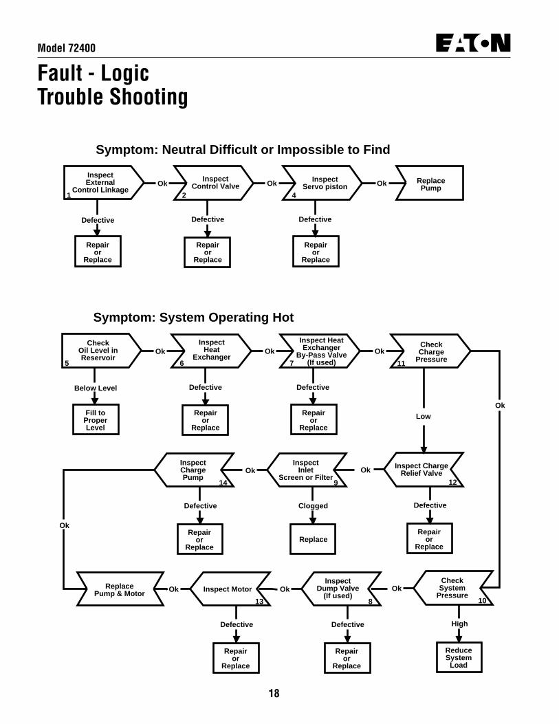
Fault - LogicTrouble ShootingThis fault - logic trouble shooting guide is a diagnostic aid inlocating transmission problems.
Match the transmission symptoms with the problem statementsand follow the action steps shown in the box diagrams. This willgive expedient aid in correcting minor problems eliminatingunnecessary machine down time.
Following the fault - logic diagrams are diagram actioncomments of the action steps shown in the diagrams. Whereapplicable, the comment number of the statement appears inthe action block of the diagrams.
Recommended Gauge Locations
18
Model 72400
InspectControl Valve
InspectServo piston
Repairor
Replace
Defective
OkOk Ok
1 2 4
ReplacePump
Symptom: Neutral Difficult or Impossible to Find
InspectExternal
Control Linkage
Repairor
Replace
DefectiveDefective
Repairor
Replace
InspectHeat
Exchanger
Inspect HeatExchanger
By-Pass Valve(If used)
Repairor
Replace
Defective
OkOk Ok
5 6 7
Symptom: System Operating Hot
CheckOil Level inReservoir
Fill toProperLevel
DefectiveBelow Level
Repairor
Replace
CheckSystem
Pressure
ReduceSystem
Load
High
Ok
10
Inspect ChargeRelief Valve
Repairor
Replace
Defective
Ok
12
InspectChargePump
Repairor
Replace
Defective
14
Inspect Motor
Repairor
Replace
Defective
Ok
13
InspectInlet
Screen or Filter
Replace
Clogged
Ok
9
CheckCharge
Pressure11
Low Ok
Ok
ReplacePump & Motor
InspectDump Valve
(If used)
Repairor
Replace
Defective
Ok
8
Fault - LogicTrouble Shooting

19
Model 72400
Repairor
Replace
Repairor
Replace
Inspect System
Relief Valves
Repairor
Replace
Defective
Ok Ok
Defective Defective
1 2 3
Symptom: Operates in One Direction Only
InspectExternal
Control LinkageInspect
Control Valve Ok ReplacePump
InspectControlValve
Inspect Dump Valve
(If used)
Repairor
Replace
Defective
OkOk Ok
11 2 8
Symptom: System Response Sluggish
CheckCharge
Pressure
Low
Defective
Repairor
Replace
InspectMotorOk
13
InspectServoPiston
4
Ok
ReplacePump & Motor
Repairor
Replace
Defective
Repairor
Replace
Defective
InspectInlet
Screen or Filter
Inspect ChargePump
Repairor
Replace
Defective
OkOk Ok
12 9 14
InspectCharge Relief
Valve
Clogged
Replace
Defective
Repairor
Replace
Fault - LogicTrouble Shooting
20
Model 72400
Fault - LogicTrouble Shooting
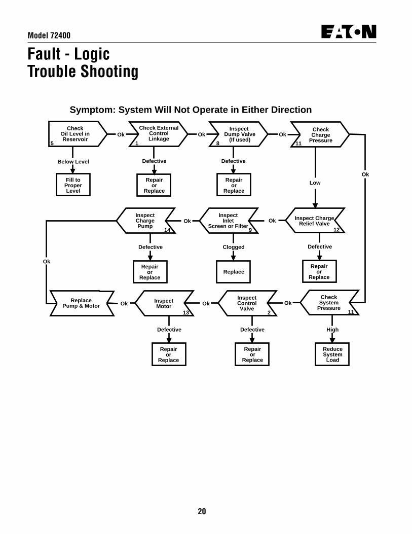
Check ExternalControlLinkage
Inspect Dump Valve
(If used)
Repairor
Replace
Defective
OkOk Ok
5 1 8
Symptom: System Will Not Operate in Either Direction
CheckOil Level inReservoir
Fill toProperLevel
DefectiveBelow Level
Repairor
Replace
CheckSystem
PressureOk
11
Inspect ChargeRelief Valve
Repairor
Replace
Defective
Ok
12
InspectChargePump
Repairor
Replace
Defective
14
InspectInlet
Screen or Filter
Replace
Clogged
Ok
9
CheckCharge
Pressure11
Low
Ok
Ok
ReplacePump & Motor
InspectMotor
Repairor
Replace
Defective
13
InspectControlValve
Repairor
Replace
Defective
Ok
2
Ok
ReduceSystem
Load
High

21
Model 72400
Fault - LogicTrouble ShootingDiagram Action Step Comments
1 Inspect External Control Linkage for:a. misadjusted or disconnectedb. binding, bent, or broken
2 Inspect Control Valve for:a. plugged control orifice(s)b. damaged mounting gasketc. misadjusted, damaged or broken neutral returnspringd. broken control connector pine. faulty destroke valve (if used)f. galled or stuck control spoolg. neutral detent or lockout switch misadjusted (if used)
3 Inspect System Relief Valves * for:a. improper pressure relief settingb. damaged or broken springc. valve held off seatd. damaged valve seat
4 Inspect Servo Piston for:a. misadjusted, damaged or broken neutral return spring
assemblyb. galled or stuck servo pistonc. damaged or missing o-ring and/or back-up ring
5 Check Oil Level in Reservoir:a. consult owner/operators manual for the proper type fluid
and level
6 Inspect Heat Exchanger for:a. obstructed air flow (air cooled)b. obstructed water flow (water cooled)c. improper plumbing (inlet to outlet)d. obstructed fluid flow
7 Inspect Heat Exchanger By-Pass Valve for:a. improper pressure adjustmentb. stuck or broken valve
8 Inspect Dump Valve for: (if used)a. held in a partial or full open position
9 Inspect Inlet Screen or Filter for:a. plugged or clogged screen or filter elementb. obstructed inlet or outletc. open inlet to charge pump
10 Check System Pressure:a. See figure 3-1 for location of pressure gauge installationb. consult owner/operators manual for maximum system
relief valve settings
11 Check Charge Pressure:a. See figure 3-1 for location of charge pressure gauge
installationb. consult owner/operators manual for maximum charge
relief valve settings
12 Inspect Charge Relief Valve for:a. improper charge relief pressure setting *b. damaged or broken springc. poppet valve held off seat
13 Inspect Motor for:a. consult owner/operator manual for motor operation and
trouble shooting
14 Inspect Charge Pump for:a. broken or missing drive keyb. damaged or missing o-ringc. excessive gerotor clearanced. galled or broken gerotor set
* System/Charge Relief ValvePressure Settings
Inlet Vacuum .203 bar [6 inHg] max.Case Pressure 1.7 bar [25 PSI] maximumCharge Pressure 17.24 to 20.68 bar
[250 to 300 PSI]System Pressure 345 bar [5000 PSI] maximum
207 bar [3000 PSI] continuous
The high pressure relief valves are all factory preset and cannotbe readjusted.
The pressure setting is stamped on each valve with a three digitnumber. To identify, multiply the noted number by 10 to get thevalves pressure setting. Example: 10 x 500 = [5000 PSI] 345 bar

22
Model 72400
Start-up Procedure
When initially starting a new or a rebuilt transmission system, itis extremely important that the start-up procedure be followed.It prevents the chance of damaging the unit which might occurif the system was not properly purged of air before start-up.
1 After the transmission components have been properlyinstalled, fill the servo pump housing at least half full withfiltered system oil. Connect all hydraulic lines and check to besure they are tight.
2 Install and adjust all control linkage.
3 Fill the reservoir with an approved oil that has been filteredthrough a 10 micron filter. Refer to Eaton Hydraulics TechnicalData sheet number 3-401 titled Hydraulic FluidRecommendations.
4 Gasoline or L.P. engines: remove the coil wire and turn theengine over for 15 seconds. Diesel engines: shut off the fuelflow to the injectors and turn the engine over for 15 seconds.
5 Replace the coil wire or return the fuel flow to the injectors.Place the transmission unit in the neutral position, start theengine and run it at a low idle. The charge pump shouldimmediately pick up oil and fill the system. If there is noindication of fill in 30 seconds, stop engine and determine thecause.
6 After the system starts to show signs of fill, slowly movepump camplate to a slight cam angle. Continue to operatesystem slowly with no load on motors until system respondsfully.
7 Check fluid level in the reservoir and refill if necessary tothe proper level with an approved filtered oil.
8 Check all line connections for leaks and tighten ifnecessary.
9 The machine is now ready to be put into operation.
10 Frequent filter changes are recommended for the first twochanges after placing the machine back into operation. Changethe first filter in 3-5 hours and the second at approximately 50hours approx. hours. Routinely scheduled filter changes arerecommended for maximum life of the hydraulic system.

23
Model 72400
Notes

Order parts from number 6-633 Parts Information booklet.Each order must include the following information.1. Product and/or Part Number2. Serial Code Number3. Part Name4. Quantity

© 2008 Eaton CorporationAll Rights ReservedPrinted in USADocument No. E-PUPI-TS011-ESupersedes 07-622December 2008
EatonFluid Power GroupHydraulics Business USA14615 Lone Oak RoadEden Prairie, MN 55344USATel: 952-937-9800Fax: 952-294-7722www.eaton.com/hydraulics
EatonFluid Power GroupHydraulics Business EuropeRoute de la Longeraie 71110 MorgesSwitzerlandTel: +41 (0) 21 811 4600Fax: +41 (0) 21 811 4601
EatonFluid Power GroupHydraulics Business Asia Pacific 11th Floor Hong Kong New World Tower 300 Huaihai Zhong Road Shanghai 200021 China Tel: 86-21-6387-9988 Fax: 86-21-6335-3912