Repair Application RAP-8 Procedures -...
6
26 CONCRETE REPAIR BULLETIN SEPTEMBER/OCTOBER 2005 ACI Repair Application Procedure 8. Copyright © 2005, American Concrete Institute. All rights reserved including rights of reproduction and use in any form or by any means, including the making of copies by any photo pro- cess, or by electronic or mechanical device, printed, written, or oral, or recording for sound or visual reproduction or for use in any knowledge retrieval system or device, unless permission in writing is obtained from the copyright proprietors. Printed in the United States of America. The Institute is not responsible for the statements or opinions in its publications. Institute publications are not able nor intended to supplant individual training, responsibility or judgment of the user, or the supplier of the information provided. Structural Disclaimer This document is intended as a voluntary field guide for the Owner, design professional, and concrete repair con- tractor. It is not intended to relieve the user of this guide of responsibility for a proper condition assessment and structural evaluation of existing conditions, and for the specification of concrete repair methods, materials, or practices by an experienced engineer/designer. It is the responsibility of the user of this document to establish health and safety practices appropriate to the specific circumstances involved with its use. ACI does not make any representations with regard to health and safety issues and the use of this document. The user must determine the applicability of all regulatory limitations before applying the document and must comply with all applicable laws and regulations, including but not limited to, United States Occupational Safety and Health Administration (OSHA) health and safety standards. Installation of Embedded Galvanic Anodes Reported by ACI Committee E 706 David W. Whitmore, *** Chair J. Christopher Ball * Peter H. Emmons ** Timothy R. W. Gillespie H. Peter Golter Fred R. Goodwin Bob Joyce Brian F. Keane Kenneth M. Lozen John S. Lund Kelly M. Page Jay H. Paul George I. Taylor Patrick M. Watson **** * Primary author of RAP Bulletin No. 6 ** Primary author of RAP Bulletin No. 7 The committee would like to thank Brandon Emmons for his illustrations in these bulletins. *** Primary author of RAP Bulletin No. 8 **** Primary author of RAP Bulletin No. 9 Repair Application Procedures CRI’s mission is: ... to be a leading resource for education and information to improve the quality of repair, restoration, and protection of concrete and other structures. Part of becoming the leading resource is knowing what other organizations have developed on the topic of concrete repair and, where applicable, to make this information available to our members. As readers of the Concrete Repair Bulletin know, ICRI has been publishing Repair Application Procedures (RAP) Bulletins, developed by the American Concrete Institute (ACI). ICRI has published the first three and, in this issue, because of the pertinent subject matter, we decided to skip ahead and publish Number 8. These Bulletins are “how-to” documents for commonly used concrete repairs. ACI is allowing ICRI to publish them in the CRB, as they are of great benefit to our I members. These documents are also available, free of charge, for a limited time on ACI’s website: www.concrete.org. Each bulletin gives a concise description of the repair method, including the purpose of the repair, when it should be used, needed surface preparation, material and equipment selection, and safety consid- erations. Step-by-step procedures are also included to help repair technicians do their jobs correctly. These bulletins are useful reference documents for facility owners, design professionals, and concrete repair contractors. Users are encouraged to tear out these pages for handy reference, or if you prefer, download these documents from ACI’s website, make copies for distribution to your field personnel, and file them for future reference.
-
Upload
phungxuyen -
Category
Documents
-
view
222 -
download
0
Transcript of Repair Application RAP-8 Procedures -...

26 ConCrete repair Bulletin SEPTEMBER/OCTOBER 2005
Reported by ACI Committee E 706
J. Christopher Ball* Bob Joyce Kelly M. Page
Peter H. Emmons† Brian F. Keane Jay H. Paul
Timothy R. W. Gillespie Kenneth M. Lozen George I. Taylor
H. Peter Golter John S. Lund Patrick M. Watson§
Fred R. Goodwin
RAP-8
Installation ofEmbedded Galvanic Anodes
David W. Whitmore‡
Chair
*Primary author of RAP Bulletin No. 6.†Primary author of RAP Bulletin No. 7.‡Primary author of RAP Bulletin No. 8.§Primary author of RAP Bulletin No. 9.
The committee would like to thank Brandon Emmons for his illustrations in these bulletins.
ACI Repair Application Procedure 8.Copyright © 2005, American Concrete Institute.All rights reserved including rights of reproduction and use in any
form or by any means, including the making of copies by any photo pro-cess, or by electronic or mechanical device, printed, written, or oral, orrecording for sound or visual reproduction or for use in any knowledgeretrieval system or device, unless permission in writing is obtained fromthe copyright proprietors. Printed in the United States of America.
The Institute is not responsible for the statements oropinions in its publications. Institute publications arenot able nor intended to supplant individual training,responsibility or judgment of the user, or the supplier ofthe information provided.
Structural DisclaimerThis document is intended as a voluntary field guide forthe Owner, design professional, and concrete repair con-tractor. It is not intended to relieve the user of this guideof responsibility for a proper condition assessment andstructural evaluation of existing conditions, and for thespecification of concrete repair methods, materials, orpractices by an experienced engineer/designer.
It is the responsibility of the user of this document toestablish health and safety practices appropriate to the specificcircumstances involved with its use. ACI does not make anyrepresentations with regard to health and safety issues and the useof this document. The user must determine the applicability ofall regulatory limitations before applying the document andmust comply with all applicable laws and regulations,including but not limited to, United States OccupationalSafety and Health Administration (OSHA) health andsafety standards.
www.concrete.org
Installation of Embedded Galvanic AnodesReported by ACI Committee E 706
David W. Whitmore,*** Chair
J. Christopher Ball*
Peter H. Emmons**
Timothy R. W. GillespieH. Peter Golter
Fred R. GoodwinBob JoyceBrian F. KeaneKenneth M. LozenJohn S. Lund
Kelly M. PageJay H. PaulGeorge I. TaylorPatrick M. Watson****
*Primary author of RAP Bulletin No. 6**Primary author of RAP Bulletin No. 7
The committee would like to thank Brandon Emmons for his illustrations in these bulletins.
***Primary author of RAP Bulletin No. 8****Primary author of RAP Bulletin No. 9
Repair Application Procedures
CRI’s mission is: ... to be a leading resource for education and information to improve the quality
of repair, restoration, and protection of concrete and other structures. Part of becoming the leading resource is knowing what other organizations have developed on the topic of concrete repair and, where applicable, to make this information available to our members.
As readers of the Concrete Repair Bulletin know, ICRI has been publishing Repair Application Procedures (RAP) Bulletins, developed by the American Concrete Institute (ACI). ICRI has published the first three and, in this issue, because of the pertinent subject matter, we decided to skip ahead and publish Number 8. These Bulletins are “how-to” documents for commonly used concrete repairs. ACI is allowing ICRI to publish them in the CRB, as they are of great benefit to our
I members. These documents are also available, free of charge, for a limited time on ACI’s website: www.concrete.org.
Each bulletin gives a concise description of the repair method, including the purpose of the repair, when it should be used, needed surface preparation, material and equipment selection, and safety consid-erations. Step-by-step procedures are also included to help repair technicians do their jobs correctly. These bulletins are useful reference documents for facility owners, design professionals, and concrete repair contractors.
Users are encouraged to tear out these pages for handy reference, or if you prefer, download these documents from ACI’s website, make copies for distribution to your field personnel, and file them for future reference.

SEPTEMBER/OCTOBER 2005 ConCrete repair Bulletin 27
Installation of Embedded Galvanic Anodes (ACI RAP-8) 1
ACI RAP Bulletin 8
Installation ofEmbedded Galvanic Anodes
FIELD GUIDE TOCONCRETE REPAIR
APPLICATION PROCEDURES
by David Whitmore

28 ConCrete repair Bulletin SEPTEMBER/OCTOBER 2005 2 Repair Application Procedures Bulletin
IntroductionIn the last 20 years, there has been an increase in the need
for concrete rehabilitation. In many structures, exposure todeicing chemicals and marine-sourced chloride is a signifi-cant cause of corrosion, playing a more detrimental role thanoriginally anticipated. Corrosion of reinforcing steel withinconcrete is recognized as a significant problem facingpresent-day owners and engineers.
The most common procedure for repairing deterioratedconcrete involves the removal of the damaged material andreplacement with new concrete or mortar. While thisaddresses the immediate serviceability requirements, it doesnot always satisfy long-term durability needs. Differences inpH, porosity, and chloride content are a few of the factorsthat may result in corrosion activity. As a result, “chip andpatch-style” repairs may fail prematurely in chloride-exposed structures.
Repair of corrosion-related deterioration in concrete struc-tures offers unique challenges. In particular, the “ring-anode” effect, also called the “halo” effect (Fig. 1), is aphenomenon that is frequently overlooked but is a commoncause of premature patch failure or increased repair volume.Generally stated, the ring-anode effect describes the increasein corrosion activity adjacent to a repair area. The ring-anodeeffect is caused by the electrochemical incompatibilitybetween reinforcing steel within a patch and the steelembedded within the surrounding concrete.
Galvanic technology—Galvanic methods of corrosionprotection have been developed for use in concrete. Thesemethods are used to combat the underlying corrosion ratherthan simply repairing the physical damage. By supplying asmall electrical current to the reinforcing steel, one can slowdown corrosion of the steel. Galvanic systems are desirablebecause they create their protective current internallythrough a natural reaction wherein the anode corrodes togalvanically protect the reinforcing steel.
Embedded galvanic anodes—Embedded galvanic anodesare installed by burying them within the concrete. Type 1embeddable galvanic anodes are available to be included instandard concrete repair (Fig. 2) or along a joint betweennew and existing concrete. Type 2 embeddable galvanicanodes are designed to be installed in sound concrete (Fig. 3).When Type 1 anodes are included in a concrete repair, theyare typically installed at the perimeter of a repair area to bein the immediate area of concern. When a suitable concreteor mortar is placed around the anode, it begins to sacrificiallyprotect the adjacent reinforcement.
What is the purpose of this repair?Embedded galvanic anodes reduce the corrosion activity
of the reinforcing steel in the vicinity of the installed anode.Anodes are installed in areas of the concrete where there is ahigh likelihood of corrosion occurring or recurring. Type 1anodes are installed to provide improved protection of rein-forcing steel in chloride-contaminated or carbonatedconcrete surrounding a patch repair. Type 2 anodes are usedin sound chloride-contaminated or carbonated concrete toprevent the onset of delamination or spalling of the concrete.
When do I use this method?Embedded galvanic anodes are attached to reinforcing
steel within the patch cavity to protect the steel in concreteadjacent to the patch. For repairs in either chloride-contami-nated or carbonated concrete, embedded galvanic anodes canbe incorporated in the repair to minimize corrosion of thereinforcing steel adjacent to the repair. Embedded galvanicanodes can also be attached to reinforcement at the interfaceof new and existing chloride-contaminated concrete. Exam-ples of uses include bridge deck widening, replacement ofdeck joint nosings, or concrete pile jacketing.
During concrete condition inspections, areas of potentiallyactive corrosion of the reinforcing steel are often discovered inmechanically sound concrete. Embedded galvanic anodes canbe installed in these areas to delay corrosion damage to theconcrete. These anodes can be installed on a grid pattern over
Fig. 1—“Ring-anode” corrosion.
Fig. 2—Chloride-accelerated corrosion.
Fig. 3—Chloride-accelerated corrosion.

SEPTEMBER/OCTOBER 2005 ConCrete repair Bulletin 29 Installation of Embedded Galvanic Anodes (ACI RAP-8) 3
a large area to provide protection for reinforcing steel inconcrete that is found to be or is suspected to be contaminated.
How do I prepare the surface?Complete surface preparation as required for the application
of the repair concrete or mortar. Limit the use of bondingagents to those with low resistivity, such as slurries containingportland cement or portland cement-sand mixtures. Avoidinsulating materials such as epoxy bonding agents.
How do I select the right material?Embedded galvanic anodes should be used only in conjunc-
tion with cementitious or cementitious-polymer repairmaterials, which have a low resistivity. Resistivity of repairmaterials or concrete for use with embedded galvanic anodesshould be less than 15,000 ohm-cm. High-resistivity materialssuch as epoxies or highly polymer modified repair mortarsgreatly reduce the available galvanic current or prevent theanodes from functioning properly. If a low-resistivity materialis not suitable for the full repair, anodes can be embedded inindividual pockets of low-resistivity material. These pocketsshould completely encapsulate the anode and completely fillthe space between the anode and the concrete substrate.
What equipment do I need?The equipment needed to install Type 1 embedded
galvanic anodes in standard repairs entails only basic handtools and a DC ohm meter capable of reading 0 to 200 ohms.To install Type 2 embedded galvanic anodes in soundconcrete, the equipment required includes a reinforcing barlocator, percussion drill or core drill, basic hand tools, andDC ohm meter.
What are the safety considerations?It is the responsibility of the user of this document to
establish health and safety practices appropriate to thespecific circumstances involved with its use. ACI does notmake any representations with regard to health and safetyissues and the use of this document. The user must determinethe applicability of all regulatory limitations before applyingthe document and must comply with all applicable laws and
regulations including, but not limited to, United States Occu-pational Safety and Health Administration (OSHA) healthand safety standards.
Preconstruction meetingPrior to proceeding with the repair, a preconstruction
meeting is recommended. The meeting should include repre-sentatives from all participating parties (owner, engineer,contractor, materials manufacturer, etc.), and specificallyaddress the parameters, means, methods, and materialsnecessary to achieve the repair objectives.
Repair procedureAnode spacing in either repair type is often determined by
the engineer, and differs for each situation. Spacing of theanodes is mainly a function of steel density and the corrosive-ness of the environment. Structures with heavy reinforcementor structures in highly corrosive environments often requirecloser spacing for the anodes to function effectively.
Type 1 embedded anodes installed in standard repairs—As in standard patch repairs, all deteriorated concrete shouldbe removed from around and behind the reinforcing steelinside the repair area in accordance with good concreterepair practice (Fig. 4). Sufficient clearance between theanode and the substrate concrete should be provided(minimum of 3/4 in. [19 mm] or 1/4 in. [6 mm] larger thanthe nominal maximum size of the coarse aggregate used inthe repair material, whichever is greater). The exposed rein-forcing bar in the repair area should be thoroughly cleanedand at least the visible surfaces should be cleaned to a brightmetal surface to facilitate good electrical connections wherethe anodes are attached. Prior to installation, electrical conti-nuity of the reinforcing bar within the repair area should beconfirmed with the use of a DC ohm meter (Fig. 5).
Anode spacing is as specified by the engineer, with theanodes placed along the perimeter of the repair area. Eachanode should then be securely connected to the reinforcingsteel (Fig. 6 and 7). If less than 1 in. (25 mm) of cover exists,the anode should be placed beneath the bar (away from thesurface of the concrete). Once installed, the electrical
Fig. 4—Deteriorated concrete removed. Fig. 5—Checking continuity of reinforcing steel.

30 ConCrete repair Bulletin SEPTEMBER/OCTOBER 2005 4 Repair Application Procedures Bulletin
connection between the anode and the reinforcing steelshould be confirmed (Fig. 8). The resistance of the electricalconnection should be less than 1 ohm. Finally, the patchcavity is filled with a compatible repair material, usingnormal patching procedures and taking care to completelyencase the anode.
Type 2 embedded anodes installed in sound concrete—Reinforcing steel in the area of the desired installation shouldbe located and marked on the concrete surface (Fig. 9). Basedon the location of the reinforcing steel, the anode locationshould be marked, and a hole of appropriate size should bedrilled to accommodate the anode (Fig. 10). A location forconnection of the anode to the reinforcing steel should thenbe marked, drilled if necessary, and a connection made(Fig. 11), either within the original hole or in a secondary
Fig. 6—Tying tool and anode.
Fig. 7—Tying in anode.
Fig. 8—Confirming connection to reinforcing steel.
Fig. 9—Locating reinforcing steel.
Fig. 10—Coring hole for anode.
Fig. 11—Secondary hole with reinforcing steel connection.
SEPTEMBER/OCTOBER 2005 ConCrete repair Bulletin 31 Installation of Embedded Galvanic Anodes (ACI RAP-8) 5
hole. Continuity of the reinforcing steel in the location of instal-lation should be verified with a DC ohm meter.
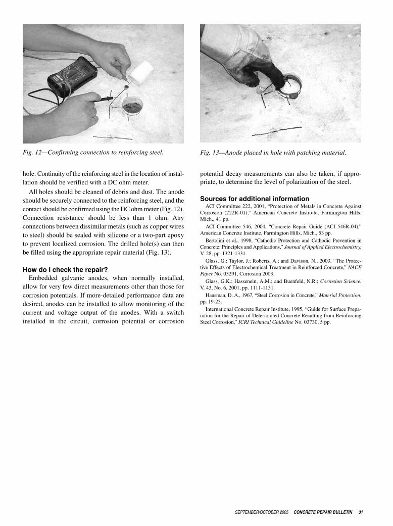
All holes should be cleaned of debris and dust. The anodeshould be securely connected to the reinforcing steel, and thecontact should be confirmed using the DC ohm meter (Fig. 12).Connection resistance should be less than 1 ohm. Anyconnections between dissimilar metals (such as copper wiresto steel) should be sealed with silicone or a two-part epoxyto prevent localized corrosion. The drilled hole(s) can thenbe filled using the appropriate repair material (Fig. 13).
How do I check the repair?Embedded galvanic anodes, when normally installed,
allow for very few direct measurements other than those forcorrosion potentials. If more-detailed performance data aredesired, anodes can be installed to allow monitoring of thecurrent and voltage output of the anodes. With a switchinstalled in the circuit, corrosion potential or corrosion
potential decay measurements can also be taken, if appro-priate, to determine the level of polarization of the steel.
Sources for additional informationACI Committee 222, 2001, “Protection of Metals in Concrete Against
Corrosion (222R-01),” American Concrete Institute, Farmington Hills,Mich., 41 pp.
ACI Committee 546, 2004, “Concrete Repair Guide (ACI 546R-04),”American Concrete Institute, Farmington Hills, Mich., 53 pp.
Bertolini et al., 1998, “Cathodic Protection and Cathodic Prevention inConcrete: Principles and Applications,” Journal of Applied Electrochemistry,V. 28, pp. 1321-1331.
Glass, G.; Taylor, J.; Roberts, A.; and Davison, N., 2003, “The Protec-tive Effects of Electrochemical Treatment in Reinforced Concrete,” NACEPaper No. 03291, Corrosion 2003.
Glass, G.K.; Hassenein, A.M.; and Buenfeld, N.R.; Corrosion Science,V. 43, No. 6, 2001, pp. 1111-1131.
Hausman, D. A., 1967, “Steel Corrosion in Concrete,” Material Protection,pp. 19-23.
International Concrete Repair Institute, 1995, “Guide for Surface Prepa-ration for the Repair of Deteriorated Concrete Resulting from ReinforcingSteel Corrosion,” ICRI Technical Guideline No. 03730, 5 pp.
Fig. 12—Confirming connection to reinforcing steel. Fig. 13—Anode placed in hole with patching material.