Creating Mobile Landing Pages With Zestadz Landing Pages Tool

REPORT BY THE UNIVERSITY OF WASHINGTON
Renewable Solar Energy for Ebey’s Landing National Historical Reserve
May 2007
Prepared for:
University National Park Energy Partnership Program and
National Park Service
Prepared by:
Philip C. Malte and Mary A. Hamann Energy and Environmental Combustion Laboratory
Department of Mechanical Engineering University of Washington Seattle, WA 98195-2600
Phone: 206-685-2171 E-mail: [email protected]

Renewable Solar Energy for Ebey’s Landing National Historical Reserve
Introduction The purpose of this project is to provide solar PV for Ebey’s Landing National Historical Reserve (EBLA), located on central Whidbey Island, in Puget Sound, Washington state. The agreement with the University National Park Energy Partnership Program (UNPEPP) required the evaluation, design, specification, purchase, and installation of a solar PV system, leading to solar generation of electricity for a site within EBLA. The funding for the project provided by UNPEPP allowed for the purchase and installation of a 1 kw (nominal, peak) grid-tied solar PV system. This installed system is shown in Figure 1. This includes the 5 panels, each rated at 205 watts, mounted on the south facing roof, and the electrical components placed on the northeast side of the building, including DC-AC inverter (white), DC circuit breaker, AC circuit breaker, and meter. The balance of project funding was used for evaluation of sites for solar PV at EBLA, design and specification of the system, and competitive selection of the vendor.
Figure 1. 1 kw (nominal, peak) solar PV system installed at EBLA
This report is arranged into the following sections:
• Evaluation of sites • Agreements with site • Selection and specifics of the PV system • Installation of the PV system.
1

Evaluation of Sites Ebey’s Landing National Historical Reserve is unique within the National Park Service in that most of the land is held privately. National Park Service land includes two farms with buildings plus additional land farmed. In our site evaluation the NPS farms and a privately held site, the Au Sable Institute of Environmental Studies, have been considered. An overview of EBLA is shown in Figure 2 below. The total land area is about 11,350 acres. All of the sites evaluated are south of Coupeville, the village (of about 2000 population) seen on the south shore of Penn Cove. Coupeville is the Island County seat. NPS farm #1 is near the large red dot immediately south of Coupeville, and NPS farm #2 is near the cluster of red dots south and somewhat east of the large central red dot. The other NPS farming area *farm #3) is near the red dots south and west of Coupeville, just to the east of the forested area. The Au Sable Institute is near the east-most red dot (which is a small dot).
Figure 2. Ebey’s Landing overview (2003).
Dark green is forest, light green is agriculture. Criteria used for evaluating the potential sites are listed are follows:
1. South facing roof of moderate slope. 2. Structural sound roof. 3. Roof must have adequate area (100 sq ft) and area should be continuous. 4. The site should indicate willingness to cooperate with UW during the
engineering and installation of the system and during any subsequent monitoring of the system.
2

5. The site should indicate willingness for the system to be shown to students and members of the community interested in learning about solar PV.
Four sites were visited and evaluated in early September, 2006:
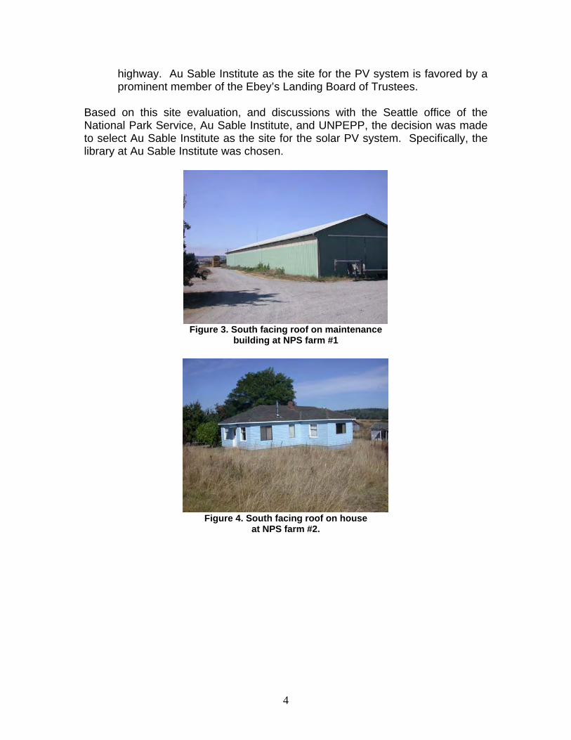
1. NPS farm #1, located in the center of EBLA. This farm has several modern buildings, built of metal roofing and siding. While most of the roofs face east and west, a few face south. One of two buildings with a south facing roof is the maintenance building shown in Figure 3.
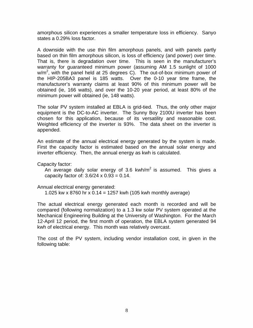
2. NPS farm #2, located approximately one mile south of NPS farm #1. This farm has traditional wood-construction farm buildings – the roofs face east and west. Only the house, at the south edge of the farm, has a south facing roof. This is shown in Figure 4.
3. NPS farm #3, located at the west side of Ebey’s Landing. This farm has no farm buildings, only land that is farmed. Next to the farm is a grassy area and a public building. This is shown in Figure 5. A platform supporting solar panels could be installed in the grassy area. The building is inappropriate because its roofs slope east and west, and to its east a stand of fir trees is located.
4. Au Sable Institute, located a few miles east of NPS farm #1. Au Sable Institute is a non-profit focusing on environmental studies and education. Au Sable Institute at Ebey’s Landing focuses on prairie and forest restoration. Two buildings were identified as potential PV sites. The garage shown in Figure 6, and the library shown in Figure 7.
Evaluation of the sites led us to the following conclusions:
1. NPS farm #1 meets criteria 1-3, but is weak on criteria 4 and 5. Uncertainty exists regarding enthusiasm of the farm tenant for the PV installation.
2. NPS farm #2 meets criteria 1 and 2, and appears to meet criteria 4 and 5, but is inadequate on criteria #3. As seen in Figure 2, the roof area is limited and discontinuous.
3. NPS farm #3 could be used, but would require the construction of a platform to hold the PV panels. This would add cost – that is unavailable in the budget. Because of its location, and because of EBLA personnel on site, farm #3 appears stronger in criteria 4 and 5 than farms #1 and #2.
4. Au Sable Institute meets criteria 1-3, and appears well positioned regarding criteria 4 and 5. Au Sable Institute management has shown strong cooperation and enthusiasm for this project – see Memorandum of Understanding appended. At least two buildings could hold the PV panels, though the library shown in Figure 5 appears to be the better choice because of its unobstructed view south. The garage has some shielding of sunlight by tress to the west. Au Sable Institute is well positioned to show and demonstrate solar PV both in its own education programs and in community outreach. The site is very accessible, being a few miles south of Coupeville. The library roof can be seen from the
3
highway. Au Sable Institute as the site for the PV system is favored by a prominent member of the Ebey’s Landing Board of Trustees.
Based on this site evaluation, and discussions with the Seattle office of the National Park Service, Au Sable Institute, and UNPEPP, the decision was made to select Au Sable Institute as the site for the solar PV system. Specifically, the library at Au Sable Institute was chosen.
Figure 3. South facing roof on maintenance
building at NPS farm #1
Figure 4. South facing roof on house
at NPS farm #2.
4

Figure 5. Potential site for PV platform
Next to NPS farm #3.
Figure 6. South facing roof on garage
at Au Sable Institute.
Figure 7. South facing roof on library
at Au Sable Institute.
5

Agreements with Site Since the site chosen, Au Sable Institute, is private, rather than governmental, it has been necessary to negotiate two agreements with the site:
• A memorandum of understanding (MOU) • An easement.
The MOU was written between Au Sable Institute at Whidbey Island (ie, the Pacific Rim division of the Au Sable Institute) and the Energy and Environmental Combustion Laboratory of the Department of Mechanical Engineering of the University of Washington, and signed by Dr. Robert Pelant, Pacific Rim Director, Au Sable Institute, and Dr. Philip Malte, Energy and Environmental Combustion Laboratory Director. The MOU is appended to this report. The easement for the solar PV system, providing the NPS and UW access to the system, was written between Au Sable Institute headquarters in Michigan and the Seattle office of the NPS. Rick Wagner, Chief of the Land Resources Program Center of the Pacific West Region of the NPS in Seattle coordinated the NPS’s writing and negotiation of the easement. The easement is appended to this report. Selection and Specifics of the PV System Ebey’s Landing is located in the rain-shadow of the Olympic Mountains, and thus is one of the driest parts of western Washington, receiving an annual rainfall of only about 18 inches. A significant portion of the landscape is prairie. A view of the west side of Ebey’s Landing, looking south into Puget Sound, is shown in Figure 8. Admiralty Inlet, the inlet to Puget Sound, lies at the north end (bottom, right) of this figure.
Figure 8. West side of Ebey’s Landing looking south into Puget Sound.
Because of the relatively dry climate at EBLA, solar flux is somewhat greater than elsewhere in the Puget Sound. Average annual daily solar energy striking
6

the horizontal ground in Seattle is 3.3 kwh/m2, whereas for EBLA, we expect it to fall in the 3.5-3.8 kwh/m2 range. Solar panels of high efficiency, minimum silicon usage, and unobtrusive appearance are desired for this application. Additionally, Island County required the panels to have very low reflectance, so that Navy operations at a nearby “touch-and-go” landing strip would not be impacted by glare. This was a building permit requirement. Early on, upon checking availability and pricing, it was found that many high efficiency panels, in the small quantity for a 1 kw system, were either out of stock or significantly over-priced, because of the strong worldwide and California demand for solar PV equipment. Traditional polycrystalline silicon panels, with large-scale grains, were available at reasonable cost, but these did not meet our requirements of high efficiency and pleasing appearance. Further search found hybrid solar panels, consisting of an inner crystalline silicon wafer and outer layers of thin film amorphous silicon. Efficiency is high: the rated cell efficiency is 20.2%. The use of silicon is small: that is, the combined thickness of the inner crystalline silicon wafer and the two outer amorphous silicon thin films is only 0.2 mm. Reflection of light from the panels is very small: the panels have been selected for use at airports because of their low glare. Cost is $5 per watt-rated. The panels are offered by Sanyo company under the name HIT, for heterojunction with intrinsic thin layer (or HIP, for HIT panels). The silicon cells are manufactured in the US, and the panels are assembled in Mexico. For this project, we purchased five Sanyo HIP 205BA3 panels, for a total system rating of 1025 watts electric. The specifics on this panel are:
Rated (max) power = 205 watts (assumes AM 1.5 sunlight of 1000 w/m2, with panel held at 25 degrees C)
Open circuit voltage (at rated condition) = 68.8 volts Short circuit current (at rated condition) = 3.84 Fill factor = 0.78 Cell efficiency = 0.202 Panel efficiency = 0.174 Panel size = 1.319 m x 0.894 m Panel weight = 14 kg.
The Sanyo data sheet is appended to this report. All PV panels lose efficiency and some power as they heat up. On a bright, sunny, warm day with nominal wind, it is not unusual for a panel to reach 60-70 degrees C. Crystalline and polycrystalline PV panels tend to lose 0.4% (relative) of their efficiency for every 1 degree C above 25 degrees C. Thin film
7
amorphous silicon experiences a smaller temperature loss in efficiency. Sanyo states a 0.29% loss factor. A downside with the use thin film amorphous panels, and with panels partly based on thin film amorphous silicon, is loss of efficiency (and power) over time. That is, there is degradation over time. This is seen in the manufacturer’s warranty for guaranteed minimum power (assuming AM 1.5 sunlight of 1000 w/m2, with the panel held at 25 degrees C). The out-of-box minimum power of the HIP-205BA3 panel is 185 watts. Over the 0-10 year time frame, the manufacturer’s warranty claims at least 90% of this minimum power will be obtained (ie, 166 watts), and over the 10-20 year period, at least 80% of the minimum power will obtained (ie, 148 watts). The solar PV system installed at EBLA is grid-tied. Thus, the only other major equipment is the DC-to-AC inverter. The Sunny Boy 2100U inverter has been chosen for this application, because of its versatility and reasonable cost. Weighted efficiency of the inverter is 93%. The data sheet on the inverter is appended. An estimate of the annual electrical energy generated by the system is made. First the capacity factor is estimated based on the annual solar energy and inverter efficiency. Then, the annual energy as kwh is calculated. Capacity factor:
An average daily solar energy of 3.6 kwh/m2 is assumed. This gives a capacity factor of: 3.6/24 x 0.93 = 0.14.
Annual electrical energy generated:
1.025 kw x 8760 hr x 0.14 = 1257 kwh (105 kwh monthly average) The actual electrical energy generated each month is recorded and will be compared (following normalization) to a 1.3 kw solar PV system operated at the Mechanical Engineering Building at the University of Washington. For the March 12-April 12 period, the first month of operation, the EBLA system generated 94 kwh of electrical energy. This month was relatively overcast. The cost of the PV system, including vendor installation cost, in given in the following table:
8

Table 1 Solar PV System Installed Cost Item Cost 1. 5 PV Panels Sanyo HIP-205BA3 $5220 2. Sunny Boy 2100U Inverter $1200 Major Equipment ($6420) 3. Ancillary Components – mounting rack, electrical connectors, DC and AC breakers, wire, conduit, fittings, meter and socket, grounding
$1060
4. Permit $100 5. Shipping $375 6. Electrical and mechanical installation $1375 Total installed cost $9330
Installation of PV System The solar PV system was installed during the second week of March 2007, and operation of the system began March 12, 2007. Certification of the system by the local utility, Puget Sound Energy, occurred during the third week of March 2007. The site is the Library Building at the Au Sable Institute of Environmental Studies. The roof upon which the five panel array is mounted faces south and has an unobstructed view south. Figure 9 shows the installation of the panels, and Figure 10 shows the completed installation. Typically, morning overcast (Figure 9) gives way to afternoon sun (Figure 10) in the Puget Sound.
Figure 9. Installation of the five panel array.
9
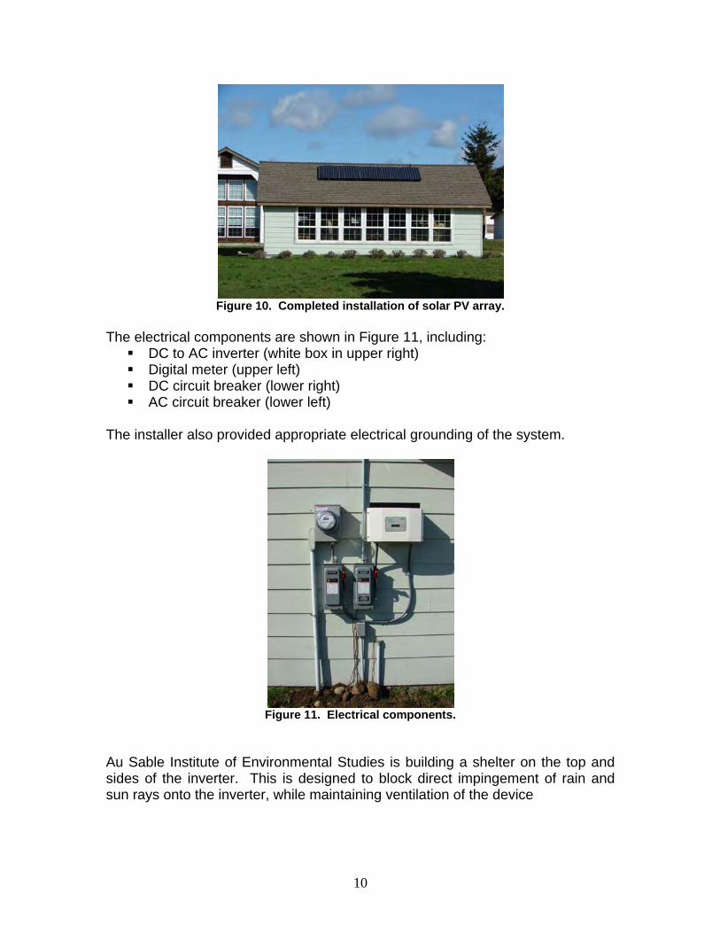
Figure 10. Completed installation of solar PV array.
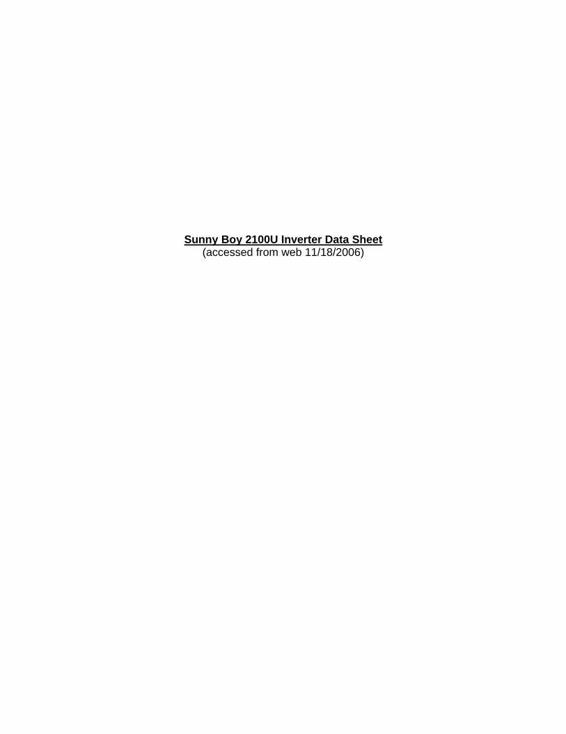
The electrical components are shown in Figure 11, including:
DC to AC inverter (white box in upper right) Digital meter (upper left) DC circuit breaker (lower right) AC circuit breaker (lower left)
The installer also provided appropriate electrical grounding of the system.
Figure 11. Electrical components.
Au Sable Institute of Environmental Studies is building a shelter on the top and sides of the inverter. This is designed to block direct impingement of rain and sun rays onto the inverter, while maintaining ventilation of the device
10

Au Sable Institute plans to use the solar PV system in its education programs and in outreach to the EBLA and Whidbey Island communities. The University of Washington will participate in this activity as time permits. The vendor, Fire Mountain Solar of Mt. Vernon, Washington, is also interested in participating in education and outreach. Acknowledgements The University of Washington wishes to thank the following individuals and organizations, without whose support and assistance this project would not have been successful:
University National Park Energy Partnership Program, and Dr. Jamie Winebrake, Director, Rochester Institute of Technology.
National Park Service, and Pacific West Region, Seattle, WA. Au Sable Institute of Environment Studies, and Dr. Robert Pelant, Director
of the Pacific Rim Division, Whidbey Island, WA. Mr. Rick Wagner, Chief, Land Resources Program Center, Pacific West
Region, National Park Service, Seattle, WA. Mr. Tim Nelson, Fire Mountain Solar, Mt. Vernon, Washington. Mr. Steve Butterworth and Mr. Joe Dunstan, Pacific West Region, National
Park Service, Seattle, WA. Mr. Leigh Smith and Ms. Gretchen Luxenberg, Ebey’s Landing National
Historical Reserve, National Park Service, Whidbey Island, WA. Sanyo Solar USA, Carson, CA. David Love, Sunwize, Inc., Olympia, WA. Ebey’s Landing Board of Trustees Island County, Washington.
11

Sanyo HIT Solar PV Data Sheet (accessed from web 10/30/2006)

HIT PHOTOVOLTAIC MODULESModels: HIP-180BA3, HIP-186BA3, HIP-190BA3, HIP-195BA3, HIP-200BA3, HIP-205BA3
Proprietary TechnologySANYO HIT (Heterojunction with Intrinsic Thin layer) solar cells are hybrids of single crystalline silicon surrounded by ultra-thin amorphous silicon layers.
High EfficiencySANYO HIT solar panels are a leader in cell and module efficiency. With models up to 16.2 Watts per sq. foot (17.4% module efficiency) you obtain maximum power within a fixed amount of space. You save costs for using fewer support materials, wiring, and spend less time installing. The powerful modules are ideal for grid-connected solar systems, areas with performance-based incentives, and renewable energy credits.
Temperature AttributesAs temperatures rise, SANYO HIT solar panels produce more electricity (kWh) than conventional crystalline silicon solar panels at the same temperature.
Unique Structure SANYO HIT solar panels have a black anodized double-wall aluminum frame. The panels come pre-equipped with a touch-safe junction box, lead wires, MCTM plug-n-play connectors, and a unique mounting lip, all of which help to minimize support structure materials, installation time and costs.
Valuable Features SANYO HIT solar panels have no moving parts and weigh less than 31 pounds (14kg). The panels are 100% emission and noise free. The panels come with a 20-year Limited Power Output Warranty and a 2-year Limited Product Workmanship Warranty. Panels are UL 1703 safety rated for wind, fire and hail. You can transport the panels to a site using less space and our eco-package minimizes cardboard waste deposited in a customer’s trash.
Quality, Ratings, ReliabilitySANYO silicon wafers are manufactured in the USA, and the panels are assembled in Mexico. All SANYO solar factories in North America are ISO 9001 and 14001 certified. The panels undergo strict inspections to ensure electrical, mechanical, environmental, and visual compliance. SANYO’s conservative model ratings give customers more kWh per rated kW, and assist to more accurately predict performance and financial economics.
5 6 7 8 9 10 11 12 13 14 15 16 17 18 19Time (Hours)
Nor
mal
ized
Out
put P
ower
1.0
0.5
0
SANYO HIT
C-Si
10% More Energy
Increased Energy When Using SANYO HITModule Temperature 75°C
Kobe, Japan
28 July ’02
Faced due South
Tilt angle 30゜
© 10 August 2006Sanyo Energy (USA) Corp.
Power Output: 180 - 205 WattsCell Efficiency: 17.8% - 20.2%
Module Efficiency: 15.3% - 17.4%
Unnecessary Section When Using SANYO HIT
SANYO HIT Solar Cell Structure

! CAUTION! Read the operating instructions carefully before use of these products.
Visit www.sanyo.com or contact our Authorized Representatives
for more information:
0.00
0.50
1.00
1.50
2.00
2.50
3.00
3.50
4.00
4.50
0 20 40 60 80
Dependence on Irradiance
(Reference Data for 200 Watt Model)
Cell Temp. 20oC
Voltage (V)
Cur
rent
(A)
1000W/m2
800W/m2
600W/m2
400W/m2
200W/m2
0.00
0.50
1.00
1.50
2.00
2.50
3.00
3.50
4.00
4.50
0 20 40 60 80
0 oC
25 oC
50 oC75 oC
Dependence on Temperature
AM-1.5, 1000W/m2
Voltage (V)
Cur
rent
(A)
(Reference Data for 200 Watt Model)
Note: Specifications and products above may change without
notice.
Dimensions
SideFront Back
Connector (MC™ Plug)
Junction Box
Label
negative ( - ) positive ( + )
Ground Hole (1 place)
894 (35.2) 35 (1.4) 440 (17.3)
1319
(51.
9)
112
(4.4
)
Unit: mm (Inches)
18.3 (0.7)
35 (1
.4)
Section A-A’
Electrical Specifications 180 186 190 195 200 205Rated Pow er (Pmax)1 W 180 186 190 195 200 205Maximum Pow er Voltage (Vpm) V 54.0 54.4 54.8 55.3 55.8 56.7Maximum Pow er Current (Ipm) A 3.33 3.42 3.47 3.53 3.59 3.62Open Circuit Voltage (Voc) V 66.4 67.0 67.5 68.1 68.7 68.8Short Circuit Current (Isc) A 3.65 3.71 3.75 3.79 3.83 3.84Minimum Pow er (Pmin) W 162.0 167.4 171.0 175.5 180.0 184.5Max System Voltage (Vsys) V 600 600 600 600 600 600Series Fuse Rating A 15 15 15 15 15 15Temperature Coefficient (Pmax) %/oC -0.33 -0.30 -0.30 -0.30 -0.29 -0.29Temperature Coefficient (Voc) V/oC -0.173 -0.168 -0.169 -0.170 -0.172 -0.172Temperature Coefficient (Isc) mA/oC 1.10 0.85 0.86 0.87 0.88 0.88Electrical Tolerance % +/- 10 +/- 10 +/- 10 +/- 10 +/- 10 +/- 10PTC Rating2 W 168.0 174.9 178.7 183.5 188.7 193.4Cell Ef ficiency % 17.8 18.4 18.8 19.3 19.7 20.2Module Efficiency % 15.3 15.8 16.1 16.5 17.0 17.4Pow er per Square Foot W 14.2 14.7 15.0 15.4 15.8 16.2
Mechanical SpecificationsInternal Bypass Diodes Module Area (m2)Weight (kg)NOCT (oC)
Dimensions LxWxH (mm)Cable Length -Male/+Female (mm)Cable Size / Connector TypeStatic Load Wind / Snow (Pa)Pallet Dimensions LxWxH (mm)Pieces per Full Pallet / Weight (kg)Quantity per 20'/40'/53' Container
Standard Operating Conditions (SOC) and Safety RatingsSOC Temperature3
SOC Relative HumidityHail Safety Impact VelocityFire Safety Classif ication Safety & Rating Certif icationsLimited Warranties
50PSF (2400Pa) / 39PSF (1876Pa)53x36x63in (1346x912x1600mm)
36pcs / 1102 Lbs (500kg)360pcs / 756pcs / 972pcs
Models HIP-xxxBA3
51.9x35.2x1.4in (1319x894x35mm)30.7/24.8in (780/630mm)
No.12 AWG / MCTM Connectors
4 Bypass Diodes12.69 Ft2 (1.18m2)
112oF (44.2oC)30.86 Lbs. (14kg)
-4oF to 104oF3 (-20oC to 40oC)45% to 95%
1" hailstone (25mm) at 52mph (23m/s)Class C
UL 1703, cUL, CEC2 Years Workmanship / 20 Years Pow er Output
1STC: Cell Temp. 25oC, AM1.5, 1000W/m2 2PTC: Ambient Temp. 20oC, AM1.5, 1000W/m2, 1m/s Wind 3Range defined as the monthly average low and high of the installation location
Sunny Boy 2100U Inverter Data Sheet (accessed from web 11/18/2006)
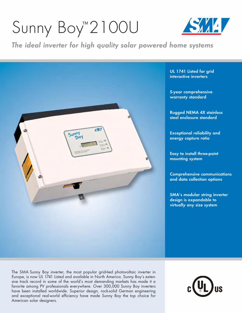
Sunny Boy 2100UThe ideal inverter for high quality solar powered home systems
UL 1741 Listed for gridinteractive inverters
5-year comprehensivewarranty standard
Rugged NEMA 4X stainlesssteel enclosure standard
Exceptional reliability andenergy capture ratio
Easy to install three-pointmounting system
Comprehensive communicationsand data collection options
SMA’s modular string inverterdesign is expandable tovirtually any size system
The SMA Sunny Boy inverter, the most popular grid-tied photovoltaic inverter inEurope, is now UL 1741 Listed and available in North America. Sunny Boy’s exten-sive track record in some of the world’s most demanding markets has made it afavorite among PV professionals everywhere. Over 300,000 Sunny Boy invertershave been installed worldwide. Superior design, rock-solid German engineeringand exceptional real-world efficiency have made Sunny Boy the top choice forAmerican solar designers.
TM
BREAKERSIZE
2p 15 Amp
SB21
00U
FLY
ER 0
2270
6 ·
Sunn
y Bo
y an
d SM
A a
re r
egist
ered
trad
emar
ks o
f SM
A T
echn
olog
ie A
G ·
Spec
ifica
tions
are
sub
ject
to c
hang
e w
ithou
t not
ice.
Distributed by:
Solar Today...Energy Tomorrow
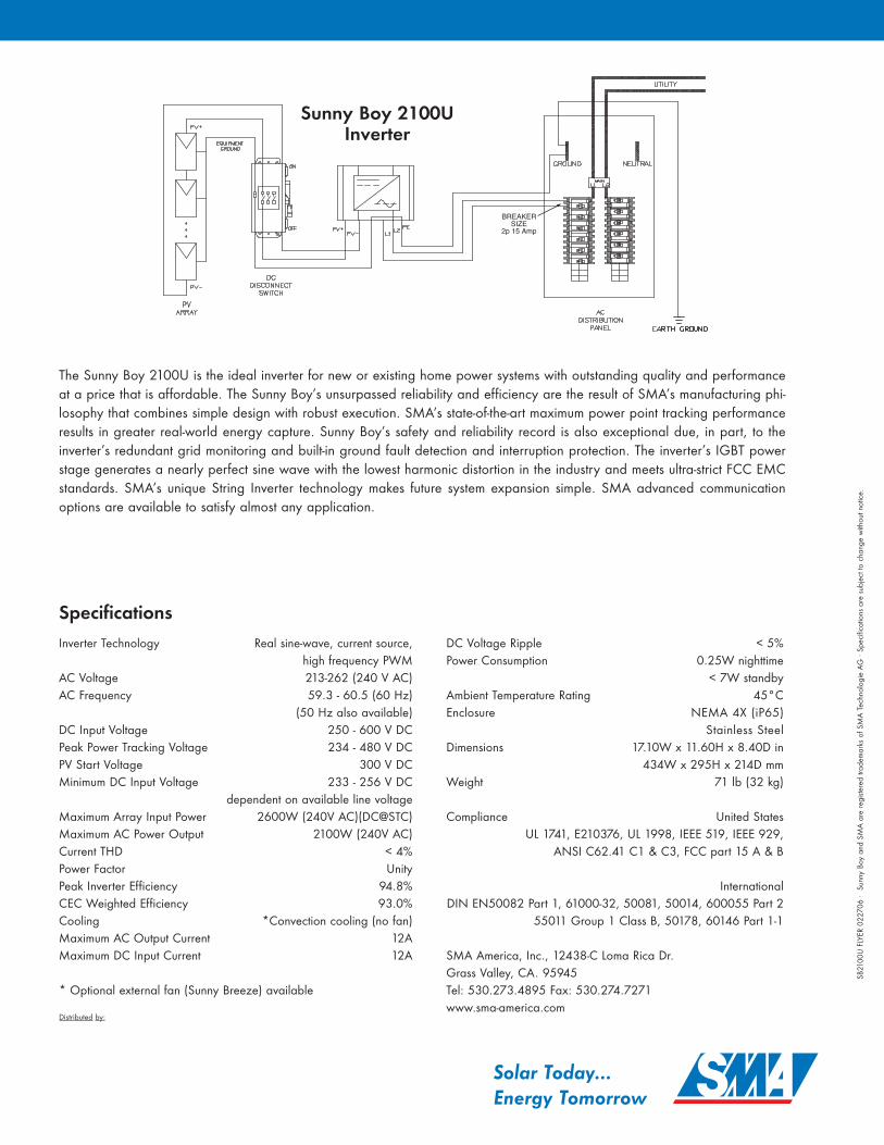
The Sunny Boy 2100U is the ideal inverter for new or existing home power systems with outstanding quality and performanceat a price that is affordable. The Sunny Boy’s unsurpassed reliability and efficiency are the result of SMA’s manufacturing phi-losophy that combines simple design with robust execution. SMA’s state-of-the-art maximum power point tracking performanceresults in greater real-world energy capture. Sunny Boy’s safety and reliability record is also exceptional due, in part, to theinverter’s redundant grid monitoring and built-in ground fault detection and interruption protection. The inverter’s IGBT powerstage generates a nearly perfect sine wave with the lowest harmonic distortion in the industry and meets ultra-strict FCC EMCstandards. SMA’s unique String Inverter technology makes future system expansion simple. SMA advanced communicationoptions are available to satisfy almost any application.
SpecificationsInverter Technology Real sine-wave, current source,
high frequency PWMAC Voltage 213-262 (240 V AC)AC Frequency 59.3 - 60.5 (60 Hz)
(50 Hz also available)DC Input Voltage 250 - 600 V DCPeak Power Tracking Voltage 234 - 480 V DC PV Start Voltage 300 V DCMinimum DC Input Voltage 233 - 256 V DC
dependent on available line voltageMaximum Array Input Power 2600W (240V AC)(DC@STC)Maximum AC Power Output 2100W (240V AC)Current THD < 4%Power Factor UnityPeak Inverter Efficiency 94.8%CEC Weighted Efficiency 93.0%Cooling *Convection cooling (no fan)Maximum AC Output Current 12AMaximum DC Input Current 12A
* Optional external fan (Sunny Breeze) available
DC Voltage Ripple < 5%Power Consumption 0.25W nighttime
< 7W standbyAmbient Temperature Rating 45°CEnclosure NEMA 4X (iP65)
Stainless SteelDimensions 17.10W x 11.60H x 8.40D in
434W x 295H x 214D mmWeight 71 lb (32 kg)
Compliance United StatesUL 1741, E210376, UL 1998, IEEE 519, IEEE 929,
ANSI C62.41 C1 & C3, FCC part 15 A & B
InternationalDIN EN50082 Part 1, 61000-32, 50081, 50014, 600055 Part 2
55011 Group 1 Class B, 50178, 60146 Part 1-1
SMA America, Inc., 12438-C Loma Rica Dr.Grass Valley, CA. 95945Tel: 530.273.4895 Fax: 530.274.7271www.sma-america.com
Sunny Boy 2100UInverter