Render Passes using Nuke Compositing Software within ...355294/FULLTEXT01.pdfRender Passes using...
28
Beteckning:________________ Department of Industrial Development, IT and Land Management Render Passes using Nuke Compositing Software within Medical Science Visualization Michael Norback June 2010 Bachelor Thesis, 15 hp, C Computer Science Creative Computer Graphics Examiner: Sharon Lazenby Co-examiner: Julia Ahlen
Transcript of Render Passes using Nuke Compositing Software within ...355294/FULLTEXT01.pdfRender Passes using...
Beteckning:________________
Department of Industrial Development, IT and Land Management
Render Passes using Nuke Compositing Software within
Medical Science Visualization
Michael Norback
June 2010
Bachelor Thesis, 15 hp, C
Computer Science
Creative Computer Graphics
Examiner: Sharon Lazenby
Co-examiner: Julia Ahlen
Render Passes using Nuke Compositing Software within Medical
Science Visualization
by
Michael Norbäck
Akademin för teknik och miljö
Högskolan i Gävle
S-801 76 Gävle, Sweden
Email:
Abstract
Today, production companies are being asked to create scenes that are almost
impossible to render. To create these impossible shots with speed and quality, the
industry has created render passes. In this research project, the aim is to learn and
understand the fastest and most efficient methods to create 3D Medical Sciences
Visualization. A deeper understanding of Render Passes using Nuke compositing
software in an industry based pipeline will answer the above statement. This project
was developed in collaboration with the Uppsala Biomedical Center (BMC) and the
Special Effects company Oddville. The final animation will also be used for BMC
medical conferences. The results revealed that the render passes did allowed for the
animation in postproduction and also saved a great deal of time.
Keywords: render passes, compositing, medical science visualization, Nuke,
Maya

Table of Contents
1 Introduction ............................................................................................................. 1 1.1 Question and purpose ................................................................................................... 1
1.2 Background .................................................................................................................. 1
1.3 Computer generated images ......................................................................................... 2
1.4 Compositing functions ................................................................................................. 2
1.5 Render passes ............................................................................................................... 3
1.6 Render passes needed for project .................................................................................. 4
1.7 History of render passes ............................................................................................... 4
2 Biomedical Center Research ................................................................................. 5 2.1 Project task................................................................................................................... 5
2.1.1 Mouse walk-cycle .............................................................................................. 6
2.1.2 Neuron matrix animation .......................................................................................6
2.1.3 Mouse spinal cord .............................................................................................. 6
2.1.4 Motion graphics and editing ............................................................................. 6
2.2 Project research ............................................................................................................ 6
2.3 Placement at Oddville .................................................................................................. 6
3. Project Development ............................................................................................... 7 3.1 Pre-production.............................................................................................................. 7
3.2 Production .................................................................................................................... 7
3.3 Post-production ............................................................................................................ 9
3.4 Planning the schedule ................................................................................................... 9
3.5 The Schedule.............................................................................................................. 10
3.6 Software used ............................................................................................................. 10
4 Results ................................................................................................................... 10 4.1 Pre-production............................................................................................................ 10
4.2 Production .................................................................................................................. 11
4.3 Post-production .......................................................................................................... 13
4.4 The mouse render passes ............................................................................................ 15
4.5 The neuron rotation matrix ........................................................................................ 16
4.6 The spinal cord slice render passes ............................................................................. 18
5 Discussion ............................................................................................................. 20 5.1 Different render passes used ....................................................................................... 20
5.2 Chosen render passes.................................................................................................. 19
5.3 Problems encountered ................................................................................................ 21
5.4 Discoveries throughout project ................................................................................... 21
5.5 Nuke discoveries ........................................................................................................ 22
6 Conclusions ............................................................................................................ 22
References .................................................................................................................. 24
1
1 Introduction
Imagination has almost no limit. However, computers do with render times,
processor power and software. It is often the case that a production company's
customer wants something amazing that is almost close to impossible to create.
The solution is compositing layers and rendered images. Understanding this
concept and the use for them in Medical Science Visualization Computer
Graphic (CG) is the main reason for this research. Understanding how layered
images can be used, also known as Render Passes, and what the Render Passes
consists of is crucial for working with Computer Graphics. Also, finding the
answers on how Render Passes can be used in altering the image to a new
artistic level using compositing is important for composing the final artwork. To
reach this goal of a higher understanding of compositing software, such as
Nuke’s knowledge of node based system will be gathered. This research will
review more about render settings in Autodesk Maya and, finally the tools, as
well as the capabilities of the tools in the software.
1.1 Question and purpose
This project has developed as a collaboration between the Uppsala
Biomedical Center (BMC) and the Special Effects company Oddville, where
Oddville will be my main supervisor for this research. My responsibility will be
create a storyboard and setup a production pipeline for creating an animation for
the Department of Neuron Science to display their research.
The question at issue pertains to how to create 3D Render Passes in a
pipeline to have more control in compositing. Autodesk Maya will be used to
setup and render the passes which will then be imported into the compositing
software NUKE.
1.2 Background
My introduction into Medical Science Visualization was from an earlier work at
the Karolinska Institutet, where I created a rat model. In this earlier project, I
had the possibility to learned how to create the fur and the rat. This was created
in Autodesk Maya. I simulated a customer employer/free lance scenario with
the Neuroscientist Richard Leao, who works on Alzheimer research at the
Karolinska Institute. [15] I learned how to plan out a project by using a Gant
Schedule, which is a schedule used by Sandvik. [10] From this earlier work, I
learned only a basic understanding of Render Layers. The only Render Passes
which I used were rendering out the fur in a different layer, then composted
with the Beauty Pass, and combined them together in Adobe compositing
software After Effects. A deeper understanding of the different Render Passes
and methods of creating them will be in this project by watching DVDs by
Digital Tutors, reading literature and information from the internet.
Earlier courses such as Animation, Concept Art and Compositing will be
of enormous use for this project. For example, I will have the knowledge to
create and animate 3D creatures and objects. I will have an understanding of
basic knowledge of compositing, as well as five weeks experience in After
Effects.
2
1.3 Computer generated images
First, a basic knowledge of a computer generated image is needed before
starting this research project. It is an array of pixels that creates many simpler
images which provides what we see on the screen. These simpler images are
also known as Channels. The Channels normally consist of four Channels when
working with computer graphics. These Channels are represented as Red,
Green, Blue and Alpha (RGBA) and are combine to create the final image,
where each channel has eight bits of information. Therefore together the image
has twenty-four bit color information. [11] The Alpha Channel works similar to
a Mask; A Mask is what controls the transparency of an image. For example,
the Alpha Channel shows where the object is visible as white and black for the
transparency which is being invisible.
Another item to discuss is the new Render Passes features in the Render
Options Box in Autodesk Maya. Instead of creating each texture for the
different passes, it is set up as “ready for use.” The following passes in Chapter
1.5 are some of the Render passes used in the pipelines for larger movie
industry companies, such as Industrial Light & Magic and Double Negative
which were presenting at the Australian Digital Movie Festival conference in
Sydney 2006.
1.4 Compositing functions
Compositing is the digital concept to combine images into a final shot. It
provides more artistic control than just using the final render from Maya. There
are a great number of things that an be changed in compositing. Below are some
of tools and techniques used in a standard compositing software such as Nuke
or Adobe After Effects:
Blur and Sharpen – These filter can be used for effecting Depth of
Field. This effect helps the view concentrate the eye on a selected
object. [4]
Color Correction - In Color Correction tools, the main tools for
compositing are Brightness and Contrast that can change the lightness
and darkness of the image and also control image mid-tones. Color
Saturation is used in color correction of Hue, Saturation, Value (HSV)
color space. It effects the tone of the color with less saturation where
the image turns black and white. [19]
Mattes – It is often connected to the Alpha Channel. We can create
separate passes from a technique called Rotoscoping or Keying. This
can be useful when using ID Passes to select certain parts in the image
to color correct or other changes. [11]
Multiply - When connecting the Render Passes, the information of each
layer needs to be connected. For example when adding Ambient
Occlusion Pass onto a Defuse Pass, the effect that is needed should only
be on the Multiplier where only the darken pixels shows on the final
image. [12]
3
Transformation - It is the movement of an image in X Y Z axis, as
well as the scale of the image. [13]
Transitions – Dissolve and Wipes are used to filter out parts of images
or shots to make objects disappear or appear similar to beaming a
person away in films such as Star Trek. [18]
1.5 Render passes
Render Passes are images that are used in production companies. They allow for
more control over objects within the 3D scene to create the final result within
compositing. It also has the advantage of saving render time is something is not
correct.
Ambient Occlusion Pass - Ambient Occlusion (AO) is a geometry-based
dirt shader, making corners darker. It will control soft lighting. [20] It
darkens areas where objects intersect or are close to each other.
Beauty Pass - Beauty Pass is almost a complete render of the image or
shot. It contains almost all of the Shadows, Colors and Highlights. [30]
Color Pass - Color Passes provides flat shaders without Highlights or
Shadows, providing a 2D appearance. [3]
Depth Pass - Depth Pass is also known as Z-depth. It provides pixel
information of the distances from the camera from the object. [3]
Diffuse Pass - Diffuse Pass is the color of the object rendered. It
consists of Diffuse, Illumination, Color and Texture. It will have no
Highlights, Shadows or Reflections. This pass is useful to change the
color or texture of an object. [3]
Facing Ratio Pass - Facing Ratio Pass highlights everything on the
model that is facing away from the camera. It can be used in
combination with several other passes. [3]
Global Illumination Pass - Global Illumination Passes is the effect of
light reflecting in the environment. Light, that is composed of all
colors, is reflected from objects as Protons bouncing in the 3D
environment. [21]
Indirect Pass - Indirect Pass is the processes of light reflected from
mirrors and other surfaces. [2]
Normal Pass - Normal Pass is used for increasing details for 3D
objects. It does not create extra Polygons, however it provides the
appearances of detailed geometry by using maps. [3]
Reflection Pass - Reflection Pass refers to reflections from the
environment and from the object it self. This is for use when rendering
4
shiny objects, such as vehicles. This can be very useful when creating
reflections in water. [3]
Shadow Pass - Shadow Pass is the render of casting shadows. It
appears as an Alpha Channel in a grey scale or similar to a Matte Pass.
This pass is useful in compositing to change the softness or the
transparence of the shadow. [22]
Specular Pass - Specular Pass is used to control the highlights of an
object. This will provide control over the color and brightness of the
rendered objects. Specular Pass can also be used to control a Glow filter
to create a nice effect. [3]
Sub-surface Scatter Shader (SSS) - SSS Pass is how the light
penetrates the surface of a translucent object and is scattered by
interacting with the material. [3]
Vector Pass - Vector Pass is used for motion blurring when objects are
in motion. [31]
1.6 Render passes needed for project
There are many passes that can be used in a project. I have narrowed down the
selection of the most important ones. ID Passes are needed to change the color
of objects. Z-depth can change the focus of the audiences eyes to follow the
main object or person. Passes to control the light in the scene to provide the
correct mood and feeling will also be needed. Motion blur will be needed to
create the illusion of speed and motion.
The items above can also change the believability of the scene when trying
to achieve a photo realistic style or something more artistic. The final result will
show how the Render Passes will be used.
1.7 History of render passes
There was not information on when the Render Passes were started, however
they were created and used in industry. However, they appeared in software
applications around 2007.
Render Passes was based on traditional techniques within Motion Control
Photography before the world of Computer Generated Effects. For example, a
camera would be program to move a pass of a model of a spaceship in different
passes, such as a Beauty Pass illumination of windows and a separate pass for
thrusters. The passes are then optically printed together onto real film. [5]
5
2 Biomedical Center Research
The following is written by Klas vallander about the research at the Biomedical
Center Research.
“BMC researchers are interested in the function of neuronal circuits in the
central nervous system. Neuronal circuits are essential components of the
nervous system and determine various body functions. Walking or
locomotion is believed to be initiated and modulated by signals from
higher centres in the brain like the motorcortex and the cerebellum. Once
initiated, the rhythmic activity of walking is selfsustained and for these
repetitive nerve impulses that support walking, the brain is not needed
(one classical example of this phenomenon is a chicken running without a
head). [1]
The central nervous system uses much of its computational machinery to
control motor behavior. In the spinal cord, the motor neurons responsible
for relaying the motor commands from the brain to the muscles are found.
[1]
One of the few identified populations of interneurons in the spinal cord is
the Renshaw cell population. These cells have previously been
characterized based on their electrophysiological properties. The Renshaw
cells are inhibitory interneurons located in the ventral horn of mammals
that mediate recurrent inhibition of alpha motoneurons. A potential
genetic marker for this cell population has been identified which opens the
possibility to do genetic modifications of the whole population and to study
the role of these cells in spinal neuronal networks. The aim is to decipher
neuronal networks at the single cell level. By combining mouse genetics
and live imaging with electrophysiology, a unique level of understanding
can be reached for how neuronal networks and in particular the CPG
works. To allow for visualisation at the single cell level in-vivo, A 3D two-
photon microscopy will be created. The set-up will be combined with
electrophysiological ventral rooot recordings allowing for simultaneous
recordings of motor output and interneuronal activity. The spinal cord is
extremely well suited for this approach since the penetrance of two photon
microscopy covers the entire tissue depth of interest. After application of
Ca sensitive dyes, two fluorescent signals will be detected together with
the motor activities. With the 3D possibilities of the suggested instrument,
this is a novel and unique method for circuit analysis.” [1]
2.1 Project task
The project task is to visualize complex scientific data or methods for a target
audience (the scientific community, sponsors or members of the general public)
that they can better understand what the scientist is trying to communicate. I
have obtained a project from the Department of Neuroscience at BMC at the
Uppsala University, where I have been asked to create an animation of a mouse
walk-cycle. This animation will also show the electrical response of nerves cells
in the mouse spinal cord. The signals are represented as flashes of light from
actual raw, scientific data into a matrix of animated live nerve cells, as well as a
slice from the spinal cord.
6
These type of animations may also be important when laboratories are
competing for funding grants and need to impress the board of sponsors. After
having a review at scientific web pages, it is clear that the demand for flashy 3D
animations are high, and a good presentation of data can impress much more
than just showing numbers and bar graphs.
The information and background material for this project was collected at
several meetings with Dr. Klas Kullander at BMC. Some of the concepts are
describe below:
2.1.1 Mouse walk-cycle
My task is to create a photo realistic mouse walk-cycle, as well as a X-ray view
of the mouse walking cycle. This clip will be a short loop that can be repeated.
Creating a photo realistic fur will be the greatest challenge and creating a four
legged animal rig which will make the mouse walk is a new challenge for me.
2.1.2 Neuron matrix animation
A matrix of about twelve individually modeled neurons will be created within a
transparent box, which will rotate 360 degrees, while cells are flashing to show
electrical activity.
2.1.3 Mouse spinal cord
A spinal cord is to be created connecting to the mouse, it will also have nerves
running down to the legs which needs to follow the animation of the mouse, as
well as being in view while the mouse is walking.
2.1.4 Motion graphics and editing
The Introduction title will be animated, as well as the final credits. I plan to use
motion graphics and logos within the animation. I would like to have
impressive transitions between the different parts of the animation.
2.2 Project reseach
I will research Render Passes and how they are created and used by researching
the Internet, DVDs and literature information. I will also be learning Nuke for
the first time because software, such as Combustion which my compositing
course was based on, is not relative in industry. Never the less, the program
After Effects can be used, however I was recommended by Oddville to learn
Nuke for shots and After Effects for editing and motion graphics.
2.3 Placement at Oddville
For this research project, I will be working at the Oddville office in Uppsala.
This will be similar to a short internship where I can watch and learn from
industry people. They will provide me feedback on my work, as well as guiding
me with input on planning, customer service and the time-frame for a company
pipeline for this project.
7
3 Project Development
This project will be an exercise in working directly with a client. With help
from the 3D artists at Oddville, I will gain an understanding of how “on the job”
is executed within the CG industry. Mattias Björkbacka at Oddville will be
acting as my industry supervisor and Klas Kullander, head of a Neuroscience
group at BMC who is the customer. [9] I will be setting up a meeting with
Oddville and the science group to discuss what is needed in the schedule, as
well as creating a document to fill out the costumers needs. For example, I will
need to obtained information on the targeting audience for the project and
setting the dates for final product. Information will be gathered for the different
Render Passes that may be used afterwards and a decision will be made on
which ones to use. The pipeline that will be use is the standard one used by
Oddville, which is pre-production, production and post-production that was
created by the same person. A deeper understanding of the software Nuke will
be need. Nuke is as stated before node-based and using the different elements
from the Render Passes will be combined into a final shot.
Information will be gathered to gain an understanding on how to combine
the chosen Render Passes. Since Nuke is Node based, not the same as Adobe
software that are Layered based, it will be different from anything that I have
used earlier. Therefore, a great deal of time will be needed to learn the work
process.
3.1 Pre-production
The pre-production is very much trying to sell an idea and creating an
understanding between the 3D artist and the customer. A storyboard concept
will be used as a pitch, further more the concepts and storyboards can be
updated and when the customer is satisfied the project can be signed off. Then
the next step comes into place which is the Animatic.
The Animatic is a series of movie clips put together from the storyboard.
This will provide the timing for each shot and also an understanding on how
many frames will be needed. It will also create a deeper understanding within
the two parties of what the project will look like. [6]
The next step is to create a schedule after making the animatic. The
schedule will be created knowing the dates of each step that needs to be
completed, as well as the deadlines that the school will need. At this time, it is
good to gather information about the subject from the customer, for example
raw data and photo references. I will also contact the lead programmer at the
BMC to gather data, the timing of each cell in the matrix, and the reference
pictures of cells, spinal cords and the lab mice.
3.2 Production
Production is a series of stages that consists of created 3D animation and
rendering. Below are the tasks involved:
8
The rat model needs to be examined and adjusted from my previous
project from the Karolinska Institute. The following modeling techniques will
be used, such as mesh Box Modeling and/or Sculpting using ZBrush refining
the model into a movable mouse. Since the earlier model is a rat, some changes
needs to be made of the model, especially the shape of the head and the
thickness of the tail. The Polygon mesh of the mouse needs to follow with the
changing movements of the mouse to create realistic believable movements.
After this, extra work in ZBrush is needed to create details by adding more
Polygons to sculpt. [14] When the results are suitable, they will be export as a
Normal Map. A Normal Map creates detailed geometry that is faster to render.
[26]
To create a low Polygon base mesh of Neurons using spline modeling
technique, ZBrush will be used to create a finer organic shape of the model.
ZBrush is far more superior then Maya for organic shape and also much
quicker. Then, the mesh needs to be Retopologized (changing the polygons) in
Maya to be compatible with the rendering in Mental ray.
A 3D model is used to create the spinal cord and spinal cord slice (such as
cutting the spinal cord similar to a piece of bread).
UV mapping will be needed for all of the objects, which provides the
quadrates in 3D space to assigned the textures. [25] The free software UV
Roadkill will be used because it is more user friendly then Maya's standard UV
Editor. [27]
The texturing of the objects can be created by two methods. Maps created
in Photoshop will later be placed in a fast Sub-surface Scatter Shader (fast SSS).
The maps that will be created in Photoshop are the Diffuse map, Bump map and
Specular map to create photo realistic skin texture. Further additional maps will
be created in Photoshop to control the appearance of the fur on the mouse. The
second method of texturing the objects is Procedural Textures for the X-ray
appearance.
A skeleton needs to be created which is the rigging for the mouse's
animation. A simple bone/skeleton system needs to be created. The mouse will
only be moving in a walk-cycle. No muscle systems is necessary nor any blend
shapes will be needed. After the rigging is complete the 3D mesh of the mouse
needs to be skinned (attaching the vertexes correctly to the bone system).
The last stage is to render everything. Digital Tutors states that there are
two methods to create Render Passes. One method is using the Render Options
and the other is using Render Layers. In this project, the Render Passes system
will be attempted. I will further investigated shaders that can render out in three
different passes from the same image, using the RBG channels, where Red
channel is for Ambient Occlusion pass, Blue channel for Z-depth pass and
Green channel for Directional Light pass. This technique can save the project a
great deal of render time. Another method for saving render time is to turn off
the Alpha Channel for some of the passes. [24]
When considering render formats, Oddville recommend renders should be
in High Definition (HD) format, then resize in After Effects to the wanted
format of Pal (television format).
9
3.3 Post-production
Production is a series of stages that consists of created 3D animation and Post-
production is the last stage of the pipeline. This is the place where all the
compositing will take place. Finding the right tools to merge the images and
color correcting some of the images will be created, especially the Neuron
Matrix scene where masks will be created to control the signals going through
the Neuron Matrix. Effects will be added to this as well, such as the Glow
Effect.
When it comes to the mouse shots, a large amount of operations will
happen, which will be combing the Fur Pass to the Skin Pass, dissolving or
changing the Opacity of the image allowing the X-ray Pass underneath to be
visible, then the Brain Pass will be merged on top of the X-ray pass. After
correcting the layer a Glow Effect and a Motion Blur will be connected onto the
mouse.
The spinal cord slices shot will be made up of two masks to be able to
change the color of the different segments of the model. A Z-depth Pass will be
assigned to composited layers to create focus on the middle of the slice.
After compositing the passes within Nuke the whole animation will be
clipped together in After Effects. Between these clips in After Effects, a creative
method for transitions needs to be created. Then, introduction titles and credits
will be created. The final render will be created in Pal format (H264) which is
twenty-five frames per second, as well as a Quicktime movie.
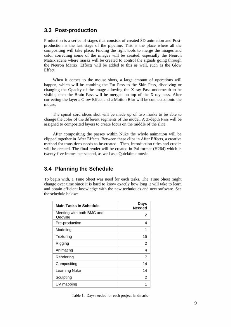
3.4 Planning the Schedule
To begin with, a Time Sheet was need for each tasks. The Time Sheet might
change over time since it is hard to know exactly how long it will take to learn
and obtain efficient knowledge with the new techniques and new software. See
the schedule below:
Table 1. Days needed for each project landmark.
Main Tasks in Schedule Days
Needed
Meeting with both BMC and Oddville
2
Pre-production 4
Modeling 1
Texturing 15
Rigging 2
Animating 4
Rendering 7
Compositing 14
Learning Nuke 14
Sculpting 2
UV mapping 1
10
3.5 The Schedule
The Gant Schedule is important to meet all of the deadlines in the production pipeline
to the final outcome. This pipeline will also create a greater understanding between the
customer and the company.
Week 1 - Storyboard, Animatic and meetings with the clients
Week 2 - Modeling, email updates for company and thesis
Week 3 - UV Mapping, Texturing for project
Week 4 - Learning how to make Fur
Week 5 - Rigging the mouse for a walk-cycle
Week 6.- Animation for the mouse walking forward
Week 7 - Rending, email updates
Week 8. - Nuke, meeting
Week 9 - Compositing, meeting
Week 10 - Presentation to the company and for the thesis exam
3.6 Software used
A variety of software will be used to achieve the final projects for Oddville.
Below is a list of the software, as well as how they will be used.
AutoDesk Maya used for Animation, Modeling, Shading, Rendering with
Mental ray.
Photoshop will be used for Textures, Fur maps, Backgrounds.
Nuke will be used compositing the different passes, as well as some
Animation.
Roadkill UV Editor will be used for UV mapping the models.
ZBrush will be used for Sculpting.
After Effects will be used for Motion Graphics.
4 Results
Results consists of render passes images from the project, as well as a
Quicktime movie file. The results are arranged in the pipeline of the industry
schedule (Pre-production, Production and Post-production).
4.1 Pre-production
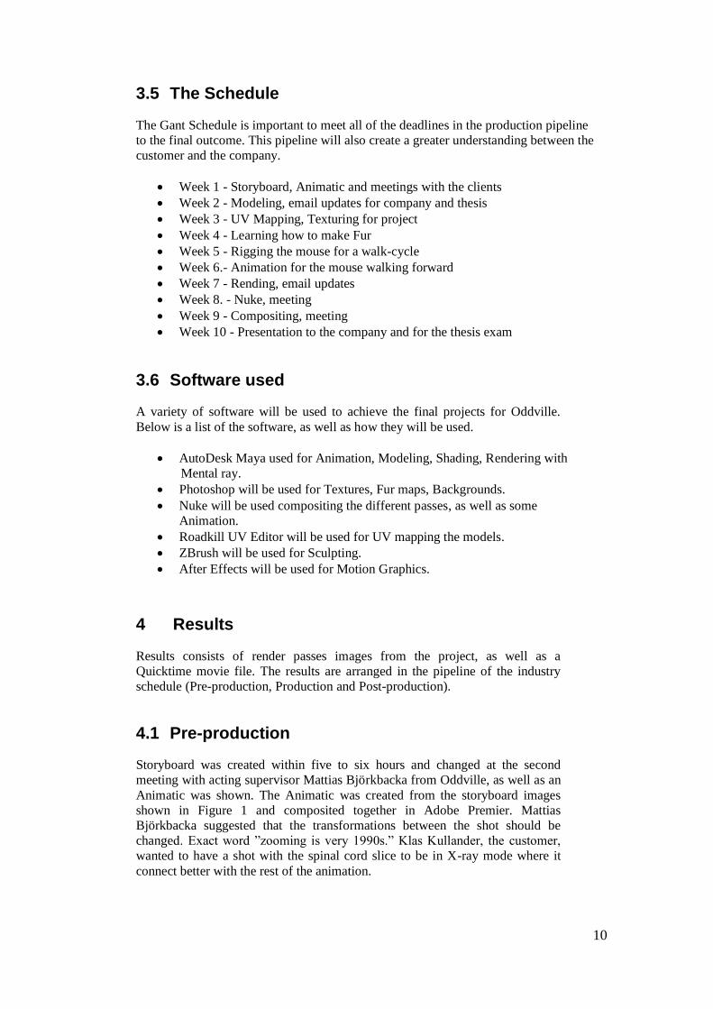
Storyboard was created within five to six hours and changed at the second
meeting with acting supervisor Mattias Björkbacka from Oddville, as well as an
Animatic was shown. The Animatic was created from the storyboard images
shown in Figure 1 and composited together in Adobe Premier. Mattias
Björkbacka suggested that the transformations between the shot should be
changed. Exact word ”zooming is very 1990s.” Klas Kullander, the customer,
wanted to have a shot with the spinal cord slice to be in X-ray mode where it
connect better with the rest of the animation.
11
Regular updates were kept on the models of the mouse, and the spinal
cord, as well as the Neuron Matrix. The Neurons had to be change since the
nerve fibers were to wide. This was easily changed with the Maya Sculpting
Tool.
Rigging was a challenge for I had never rigged a quadruped (an
animation having four legs). To create a four legged rig, references were needed
and collected on the mouse bone structure.
Figure 1. First draft of storyboard.
4.2 Production
The earlier model of the rat used at the Karolinska Institute did not meet the
requirements for this project. It was quicker to start from scratch than cleaning
up the mesh. I created my own modeling template in Photoshop. Then, a base
mesh was created using box modeling techniques. The mesh was later exported
into ZBrush for sculpting and more details, where the feet and nose was created
quickly. It took about two to three days. The model was UV wrapped in the
software UV Roadkill. Textures where created in Photoshop (Diffuse, Specular
and Bump map) and connected to a fast Surface Scatter Shader. This was test
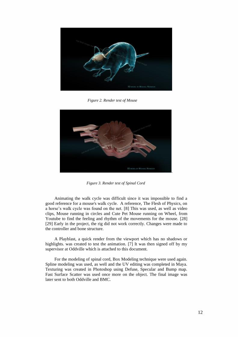
rendered and a images in Figure 2 and 3 were then sent to Klas Kullander and
Mattias Björkbacka.
12
Figure 2. Render test of Mouse
.
Figure 3. Render test of Spinal Cord
Animating the walk cycle was difficult since it was impossible to find a
good reference for a mouse's walk cycle. A reference, The Flesh of Physics, on
a horse’s walk cycle was found on the net. [8] This was used, as well as video
clips, Mouse running in circles and Cute Pet Mouse running on Wheel, from
Youtube to find the feeling and rhythm of the movements for the mouse. [28]
[29] Early in the project, the rig did not work correctly. Changes were made to
the controller and bone structure.
A Playblast, a quick render from the viewport which has no shadows or
highlights. was created to test the animation. [7] It was then signed off by my
supervisor at Oddville which is attached to this document.
For the modeling of spinal cord, Box Modeling technique were used again.
Spline modeling was used, as well and the UV editing was completed in Maya.
Texturing was created in Photoshop using Defuse, Specular and Bump map.
Fast Surface Scatter was used once more on the object. The final image was
later sent to both Oddville and BMC.
13
4.3 Post-production
Finding the right passes was not an easy task. I obtained advice from Oddville
(see Discussion for more detail). The main passes that was used for this project
were:
Beauty Passes - Color, Shadows, Highlights.
Z-depth - Depth of field.
2D Vector Pass - Motion Blur.
ID Pass - to create color corrections in post-production.
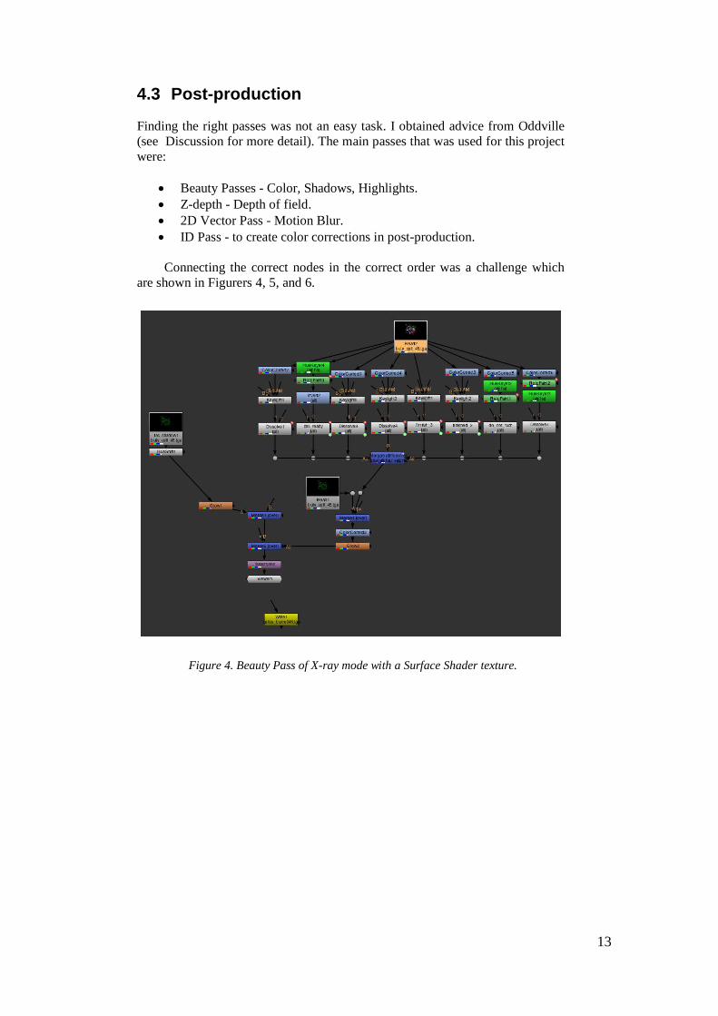
Connecting the correct nodes in the correct order was a challenge which
are shown in Figurers 4, 5, and 6.
Figure 4. Beauty Pass of X-ray mode with a Surface Shader texture.
14
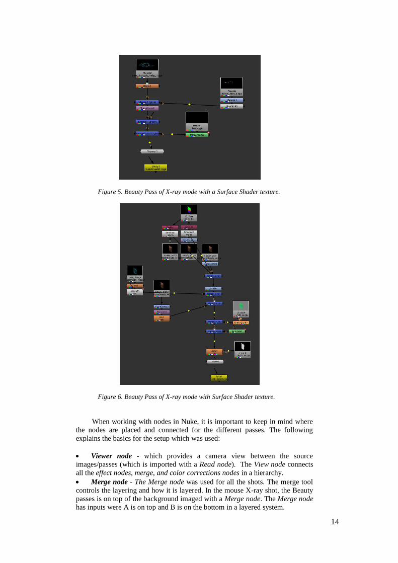
Figure 5. Beauty Pass of X-ray mode with a Surface Shader texture.
Figure 6. Beauty Pass of X-ray mode with Surface Shader texture.
When working with nodes in Nuke, it is important to keep in mind where
the nodes are placed and connected for the different passes. The following
explains the basics for the setup which was used:
Viewer node - which provides a camera view between the source
images/passes (which is imported with a Read node). The View node connects
all the effect nodes, merge, and color corrections nodes in a hierarchy.
Merge node - The Merge node was used for all the shots. The merge tool
controls the layering and how it is layered. In the mouse X-ray shot, the Beauty
passes is on top of the background imaged with a Merge node. The Merge node
has inputs were A is on top and B is on the bottom in a layered system.
15
Masks - Within the spinal cord slice shot, one masks was created by
separating the channels with a Shuffle node that was easy because the ID Pass
consisted of three colors; red, green and blue (RGB). Then the Alpha output was
selected into a mask. These masks change the colors of the models segments.
Keying node - Neuron Matrix rotation shot took the most time to create a
clean masks of the ID Pass. The Shuffle node could not be used because more
colors needed to be dealt with than just the RGB. Two different Keying nodes
were used to create the masks which were the Hue keyer (affects the HVG value
to create a matte) and the color keyer (which selects the color). The Color
Correction node was added as well to help with the different selections. When
the masking was finished a Dissolve node was created to control the flashing
signals from the Neurons.
Blur and Vector node - can be used to control the Depth of Field and the
blurriness of the shot. This node did not work for the fact that it was
rendered out in the wrong format. Nevertheless, the node used for Z-
depth is called ZBlur node and the 2D vector node is called Motion Blur 2D.
Write node – is the where the exporting of the clip is finalized. It is
important that the name is written correctly specifying that it is a sequence,
otherwise Nuke will not render the shot.
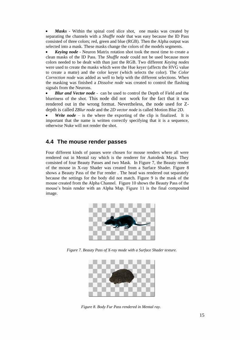
4.4 The mouse render passes
Four different kinds of passes were chosen for mouse renders where all were
rendered out in Mental ray which is the renderer for Autodesk Maya. They
consisted of four Beauty Passes and two Mask. In Figure 7, the Beauty render
of the mouse in X-ray Shader was created from a Surface Shader. Figure 8
shows a Beauty Pass of the Fur render . The head was rendered out separately
because the settings for the body did not match. Figure 9 is the mask of the
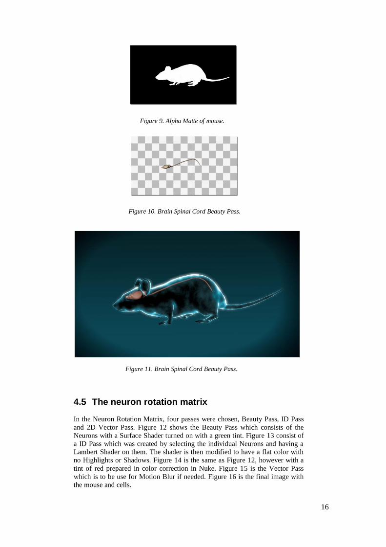
mouse created from the Alpha Channel. Figure 10 shows the Beauty Pass of the
mouse’s brain render with an Alpha Map. Figure 11 is the final composited
image.
Figure 7. Beauty Pass of X-ray mode with a Surface Shader texture.
Figure 8. Body Fur Pass rendered in Mental ray.
16
Figure 9. Alpha Matte of mouse.
Figure 10. Brain Spinal Cord Beauty Pass.
Figure 11. Brain Spinal Cord Beauty Pass.
4.5 The neuron rotation matrix
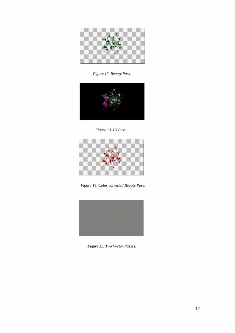
In the Neuron Rotation Matrix, four passes were chosen, Beauty Pass, ID Pass
and 2D Vector Pass. Figure 12 shows the Beauty Pass which consists of the
Neurons with a Surface Shader turned on with a green tint. Figure 13 consist of
a ID Pass which was created by selecting the individual Neurons and having a
Lambert Shader on them. The shader is then modified to have a flat color with
no Highlights or Shadows. Figure 14 is the same as Figure 12, however with a
tint of red prepared in color correction in Nuke. Figure 15 is the Vector Pass
which is to be use for Motion Blur if needed. Figure 16 is the final image with
the mouse and cells.
17
Figure 12. Beauty Pass.
Figure 13. ID Pass.
Figure 14. Color corrected Beauty Pass.
Figure 15. Two Vector Passes.
18
Figure 16. Final Image of Mouse and cells.
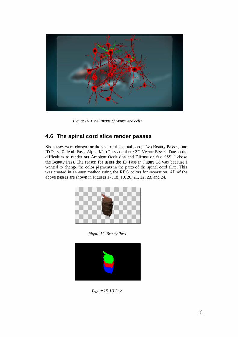
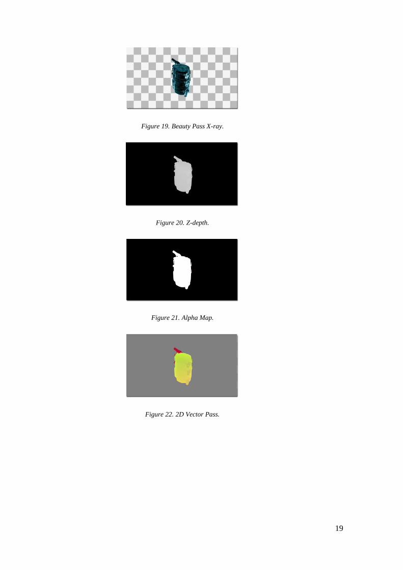
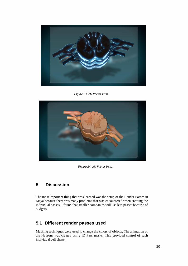
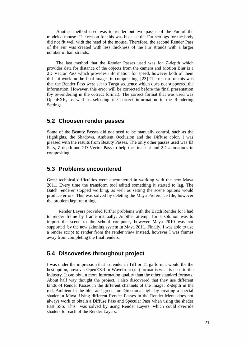
4.6 The spinal cord slice render passes
Six passes were chosen for the shot of the spinal cord; Two Beauty Passes, one
ID Pass, Z-depth Pass, Alpha Map Pass and three 2D Vector Passes. Due to the
difficulties to render out Ambient Occlusion and Diffuse on fast SSS, I chose
the Beauty Pass. The reason for using the ID Pass in Figure 18 was because I
wanted to change the color pigments in the parts of the spinal cord slice. This
was created in an easy method using the RBG colors for separation. All of the
above passes are shown in Figures 17, 18, 19, 20, 21, 22, 23, and 24.
Figure 17. Beauty Pass.
Figure 18. ID Pass.
19
Figure 19. Beauty Pass X-ray.
Figure 20. Z-depth.
Figure 21. Alpha Map.
Figure 22. 2D Vector Pass.
20
Figure 23. 2D Vector Pass.
Figure 24. 2D Vector Pass.
5 Discussion
The most important thing that was learned was the setup of the Render Passes in
Maya because there was many problems that was encountered when creating the
individual passes. I found that smaller companies will use less passes because of
budgets.
5.1 Different render passes used
Masking techniques were used to change the colors of objects. The animation of
the Neurons was created using ID Pass masks. This provided control of each
individual cell shape.
21
Another method used was to render out two passes of the Fur of the
modeled mouse. The reason for this was because the Fur settings for the body
did not fit well with the head of the mouse. Therefore, the second Render Pass
of the Fur was created with less thickness of the Fur strands with a larger
number of hair strands.
The last method that the Render Passes used was for Z-depth which
provides data for distance of the objects from the camera and Motion Blur is a
2D Vector Pass which provides information for speed, however both of them
did not work on the final images in compositing. [23] The reason for this was
that the Render Pass were set to Targa sequence which does not supported the
information. However, this error will be corrected before the final presentation
(by re-rendering in the correct format). The correct format that was used was
OpenEXR, as well as selecting the correct information in the Rendering
Settings.
5.2 Choosen render passes
Some of the Beauty Passes did not need to be manually control, such as the
Highlights, the Shadows, Ambient Occlusion and the Diffuse color. I was
pleased with the results from Beauty Passes. The only other passes used was ID
Pass, Z-depth and 2D Vector Pass to help the final cut and 2D animations in
compositing.
5.3 Problems encountered
Great technical difficulties were encountered in working with the new Maya
2011. Every time the transform tool edited something it started to lag. The
Batch renderer stopped working, as well as setting the scene options would
produce errors. This was solved by deleting the Maya Preference file, however
the problem kept returning.
Render Layers provided further problems with the Batch Render for I had
to render frame by frame manually. Another attempt for a solution was to
import the scene to the school computer, however Maya 2010 was not
supported by the new skinning system in Maya 2011. Finally, I was able to use
a render script to render from the render view instead, however I was frames
away from completing the final renders.
5.4 Discoveries throughout project
I was under the impression that to render in Tiff or Targa format would the the
best option, however OpenEXR or Wavefront (rla) format is what is used in the
industry. It can obtain more information quality than the other standard formats.
About half way thought the project, I also discovered that they use different
kinds of Render Passes in the different channels of the image; Z-depth in the
red, Ambient in the blue and green for Directional light by creating a special
shader in Maya. Using different Render Passes in the Render Menu does not
always work to obtain a Diffuse Pass and Specular Pass when using the shader
Fast SSS. This was solved by using Render Layers, which could override
shaders for each of the Render Layers.
22
Late in the project, I found that Targa did not support Z-depth, which was
a huge problem for the project. This problem will be solved later by creating a
Render Layer Override and attaching a Lambert Shader with no scan line and
with no Alpha Channel to created a fast render of Z-depth.
Another discovery was that ID Pass should be render out with the double
amount of resolution than the chosen render setting, as well as turn off anti-
aliasing. This will provide a finer mask for the image.
The last discovery, which started out as an accident then turned out to be a
positive outcome was when the mouse was animated.. The accident was when I
used too many frames than what was needed for the project. For some strange
reason, this could not be corrected. Therefore, in Post-production Mattias
suggested to have the animation speed up to real speed in the beginning and
when the mouse is transformed into X-ray mode the mouse would run in slow
motion. This accident turned out amazingly well by using the effects Time
Warp which affects the speed of clip and Frame Blending which provides a
smooth transition between the frames in After Effects. [16]
5.5 Nuke discoveries
I discovered that Nuke is most useful for clips, however not for editing and
cutting. Nuke combines the Render Passes in an organized order and is user
friendlier which also allows for customizing the setup. The Node based system
took some time to learn, however the program is powerful being able to work
with 32 bit images whereas After Effects works best with 16 or 8 bit color
information there is a difference in quality between the two systems. [17] It was
also easier to separate the different Color Channels in Nuke.
6 Conclusions
The renders from the Layer Passes works better than the new Render Passes
systems in the Render Option box in Maya. Render Layers provides more
control over the rendering output for compositing. By using the created Render
Passes, I was able to save render time by only re-rendering certain passes that
was not correct, for example re-rendering the problems with the Fur. I found the
pipeline useful for having the connection with the customer to sign off the
rendered clips which could be quickly changed.
When using Render Passes for Medical Science Computer Graphics
Visualization, they were most useful for the Neuron Matrix Rotation shot. This
provides the possiblity to control the flashing of the cells with real data in the
near future.
Working at Oddville provided me with an even more positive attitude on
my work. The work environment was amazing, both aesthetically with nice
wallpaper and paintings on the wall, however most of all the people provided a
positive working environment. The feedback from my supervisor was very
useful and greatly appreciated. The Oddville 3D artists did not help me with the
technical problems but instead put more focus on the design aspects on Motion

23
Graphics and the feeling of the animation. I also obtained insight on what kind
of passes that they used for different projects.
Overall this project has been the most rewarding project for the reason of
providing insight into industry, as well as getting to know some of the new
techniques in compositing.
24
References
Web sources
[1] Leth, G. & Thurén, T. ”Källkritik för Internet.” Styrelsen för psykologiskt
försvar, rapport 117 [in Swedish]. 2000.
http://www.psycdef.se/reports/default.asp?FileID=37. 2004-01-07.
[2] AL Hart. ”Render Plus Systems.” 2010.
http://wiki.renderplus.com/index.php?title-Indirect_Light.
[3] Olle Rydberg. ”Modeling, Texturing, Light/ Render setup, Compositing.”
Soldier modelsheet. 2000.
http://gscept.com/index.php/site/Soldier_MakingOf/ . 2004-01-07.
[4] Wikimedia. “Depth of Field.” Wikimedia Foundation Inc. 2010.
[5] Wikimedia. “Render Layers.” Wikimedia Foundation Inc. 13 July 2010.
[6] Wikimedia. “Storyboard.” Wikimedia Foundation Inc. 24 April 2010.
[7] Maya tutorials . Programming Course - “Create a Movie Clip with
Playblast.” 2010.
http://www.prog.arch.ethz.ch/ws00/tutorial/MAYA_animation.html
http:// en.wikipedia.org/wiki/Depth_of_field
[8] Carl Zimmer. “Life In Motion: the Flesh of Physics.” 26 January 2009.
http://blogs.discovermagazine.com/loom/2009/01/26/the-flesh-of-physics/
[9] Klas Kullander. “Department of Neuroscience, Uppsala University.“ 4 May
2009.
[10] Matt Scully. “Sandvik Mining and Constucation.” February 2007.
http://au.linkedin.com/pub/matt-scully/13/b09/337
[14] Pixologic. “An Artist’s Deam.” 2010.
http://www.pixologic.com/zbrushMac/bz
[15] Dr Richardson N Leao. “Karolinska Institute.” 2010.
http://admin.frontiersin.org/people/richardsonle%C3%A3o/5631/neuroscience
[16] Adobe After Effects. “Timewarp effect.” 2008.
http://help.adobe.com/en_US/AfterEffects/9.0/WS641C5190-1DAD-4150-
B17F-F339C6DF1FB2a.html
[17] Pete O’Connel. “Nuke- An Introduction for After Effects Users.” 2009.
http://magazine.creativecow.net/article/nuke-an-introduction-for-after-effects-
users
[24] Jeremy Bim. “Rendering Better Shadow Passes in Maya: 3D Render.”
2005.
http://www.3drender.com/light/shadpass.htm
[27] Roadkill Professional. “Roadkill Proefssional User’s Guide Maya
Manual.” 2010.
http://www.roadkillpro.com/Roadkill_Professional_Maya_Manual.pdf
25
[28] YouTube . “Mouse running in circles.” 2009.
http://www.youtube.com/watch?v=ND8jYZ5p9qo
[29] YouTube. “Cute Pet mouse running on Wheel.” 2009.
http://www.youtube.com/watch?v=eakdLdd2A74&feature=related
[30] Jeremy Bim. “Render Passes,Layers and 3D Compositing: 3D Render.”
2006.
http://www.3drender.com/light/compositing/index.html
[31] Revisionfx. “How do I get motion vectors of my 3D system.” 2010.
http://www.revisionfx.com/support/faqs/motion_vector_FAQs/motion_vectors/
Literature sources
[11] Antony Bolante. Adobe After Effects for Macintosh & Windows. Peachpit
Press, 2002. pp381-385.
[12] Antony Bolante. Adobe After Effects for Macintosh & Windows. Peachpit
Press, 2002. pp 372-379.
[13] Antony Bolante. Adobe After Effects for Macintosh & Windows. Peachpit
Press, 2002. pp. 192, 197-204.
[18] Antony Bolante. Adobe After Effects for Macintosh & Windows. Peachpit
Press, 2002. pp.359-361.
[19] Michael Todd Peterson, Alexander Hessler. Combustion™ Ground Rules.
Delmar learning United States, 2002. p8.
[20] Boaz Livny. Mental ray for Maya, 3ds Max, and XSI. Wiley Publishing,
inc, Canada, 2008. pp 549-622.
[21] Boaz Livny. Mental ray for Maya, 3ds Max, and XSI. Wiley Publishing,
inc, Canada, 2008. pp5-27.
[22] Boaz Livny. Mental ray for Maya, 3ds Max, and XSI. Wiley Publishing,
inc, Canada, 2008. pp326.
[23] Boaz Livny. Mental ray for Maya, 3ds Max, and XSI. Wiley Publishing,
inc, Canada, 2008. pp280-282.org/
[25] Marc André Guindon. The Modeling & Animation Handbook Alias
learning Tools. United States, 2005. pp99-129.org wiki/Rend
[26] Boaz Livny. Mental ray for Maya, 3ds Max, and XSI. Wiley Publishing,
inc, Canada, 2008. pp416-417.org/