REMOVAL ACTION REPORT - Superfund Records … · REMOVAL ACTION REPORT JAN «4 1995 SPFD ... Soil...
87
EECEIVED REMOVAL ACTION REPORT J AN «4 1995 SPFD RECIOH VII FORMER RALSTON DISPOSAL SITE Prepared for ROCKWELL INTERNATIONAL CORPORATION CEDAR RAPIDS, IOWA Project No. 1166.0282 January 1995 Prepared by Montgomery Watson 11107 Aurora Avenue Des Moines, Iowa 50322 515-253-0830 I hereby certify that this engineering document was prepared by me or under my direct personal supervision and that I am a duly Registered Professional Engineer under the laws of the State of Iowa. Signature: ________________________________ Name: ____________Jeffrey L. Coon. P.E._______ Date: ________________ Reg. No.: 11975 My registration expires December 31,1995.
Transcript of REMOVAL ACTION REPORT - Superfund Records … · REMOVAL ACTION REPORT JAN «4 1995 SPFD ... Soil...
EECEIVEDREMOVAL ACTION REPORT JAN «4 1995
SPFD
RECIOH VII
FORMER RALSTON DISPOSAL SITE
Prepared for
ROCKWELL INTERNATIONAL CORPORATIONCEDAR RAPIDS, IOWA
Project No. 1166.0282
January 1995
Prepared by
Montgomery Watson11107 Aurora Avenue
Des Moines, Iowa 50322515-253-0830
I hereby certify that this engineering document was prepared by me or under my direct personal supervisionand that I am a duly Registered Professional Engineer under the laws of the State of Iowa.
Signature: ________________________________
Name: ____________Jeffrey L. Coon. P.E._______
Date: ________________ Reg. No.: 11975
My registration expires December 31,1995.

RECEIVEDTABLE OF CONTENTS J A N 2 4,995
SPFD BRANCH PAGEREGION VII
SECTION 1 - INTRODUCTION ......................................................................................... 1
Objective...................................................................................................................... lSite Location ................................................................................................................ 1Background.................................................................................................................. 1
July 14 to August 5, 1994 ................................................................................... 1August 6 to 25, 1994 ........................................................................................... 2August 25 to September 10, 1994....................................................................... 2September 12 to 19, 1994 ................................................................................... 2September 19 to 22, 1994 ................................................................................... 2September 22 to December 20, 1994 .................................................................. 2
Construction Oversight................................................................................................ 2Montgomery Watson........................................................................................... 2EPA Region VH .................................................................................................. 2
SECTION 2 - CONSTRUCTION ACTIVITIES.................................................................. 3
Site Preparation ............................................................................................................ 3General Excavation...................................................................................................... 3
Clay Cap Extension............................................................................................. 3Buried Drums...................................................................................................... 4
Clay Cap Construction ................................................................................................. 4Placement of Clay ............................................................................................... 4Soil Testing Procedures ...................................................................................... 4Monitoring Well Extensions ............................................................................... 5
Survey Control............................................................................................................. 5Creek Bank Stabilization ............................................................................................. 7
Gabled-Concrete Mats......................................................................................... 7Geomembrane Liner ........................................................................................... 7
Drainage Control.......................................................................................................... 7Construction of Terraces, Drainage Channels and Temporary Access Road ..... 7Seeding................................................................................................................ 8
Operation and Maintenance ......................................................................................... 9Summary...................................................................................................................... 9
APPENDIX A - SOIL PERMEABILITY TEST RESULTS - BORROW AREA #1 ........... A-l
APPENDIX B - SOIL SAMPLE ANALYTICAL RESULTS - BURIEDDRUM LOCATIONS.................................................................................. B-l
APPENDIX C - ANALYTICAL RESULTS - DRUMMED MATERIALS ......................... C-1
APPENDIX D - SOIL PERMEABILITY TEST RESULTS - BORROW AREA #2 ........... D-l
TABLE OF CONTENTS
PAGE
APPENDIX E - FIELD COMPACTION REPORT .............................................................. E-l
APPENDIX F - AS-BUILT DRAWING OF GEOMEMBRANE LINER............................ F-l
APPENDIX G - AS-BUILT DRAWING OF CABLED CONCRETE.................................. G-1
APPENDIX H - FIELD TEST RESULTS-GEOMEMBRANE LINER.............................. H-l
APPENDIX I - PHOTO LOG............................................................................................... 1-1
LIST OF TABLES
TABLENO.
2-1 Field Compaction Test Results ............................................................................. 6
LIST OF FIGURES
FIGURE FOLLOWINGNO. PAGE
1-1 Site Location Map................................................................................................. 11-2 Former Ralston Disposal Site Layout................................................................... 12-1 Soil Testing Locations.......................................................................................... 42-2 General Grading.................................................................................................... 62-3 Cap Grading.......................................................................................................... 62-4 Final Grading........................................................................................................ 62-5 Cross Section Locations ....................................................................................... 62-6 Disposal Area Cap: Creek Bank Stabilization Cross Sections A-A' and B-B'.... 62-7 Dry Run Creek Crossing....................................................................................... 72-8 Erosion Control..................................................................................................... 8
SECTION 1
-MONTGOMERY WATSON •

SECTION 1
INTRODUCTION
OBJECTIVE
This Removal Action Report (RAR) has been prepared by Montgomery Watson on behalf ofRockwell International Corporation (Rockwell) for the former Ralston disposal (Ralston) site inCedar Rapids, Iowa. This RAR is submitted as a requirement of the Administrative Order onConsent, Docket Number VII-93-F-004, entered into on January 22, 1993, between Rockwelland the U.S. Environmental Protection Agency (EPA). The purpose of this RAR is tosummarize the clay capping and creek bank stabilization activities conducted as part of theremoval action and to certify their completion, consistent with the May 1994 Removal ActionWork Plan (RAWP). Certification of the construction of the dual vapor extraction remediationsystem will be prepared at a later date, under separate cover.
SITE LOCATION
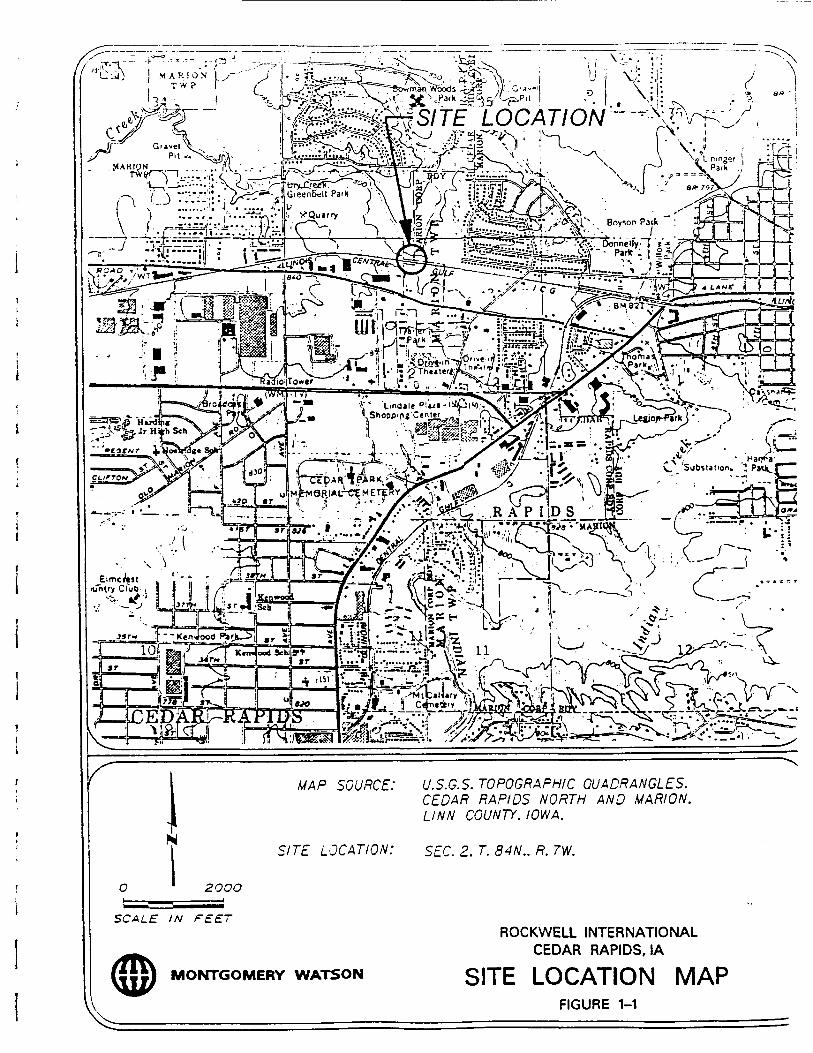
The Ralston site is located in the NE 1/4, NW 1/4, Section 2, T83N, R7W of Linn County, Iowa(Figure 1-1). The site is situated north of 228 Blairs Ferry Road in northern Cedar Rapids, Iowa.
The Ralston site consists of a former disposal area, a segment of Dry Run Creek, and a portion ofthe creek flood plain totaling approximately 1.5 acres. The steep banks of Dry Run Creek definemost of the northern edge of the former disposal area, whereas the south is bounded by theIllinois Central Gulf Railroad. The Ralston site is accessed via a gravel road north from BlairsFerry Road between the Bauer residence to the east and Don's Automotive to the west. A map ofthe Ralston site layout is presented as Figure 1-2.
BACKGROUND
Rockwell retained Montgomery Watson to provide project management assistance andconstruction management services for the clay cap and creek bank stabilization projects at theRalston site. Montgomery Watson prepared construction drawings and technical specifications(included in the RAWP) to allow Rockwell to competitively bid the project.
Following submittal and review of competitive bids, Rockwell selected WestinghouseRemediation Services, Inc. (Westinghouse) of Lakeville, Minnesota as the general contractor forconstruction of the clay cap and creek bank stabilization. Construction activities were initiatedon July 14, 1994, following a preconstruction meeting held at the site on July 13, 1994.Attending the preconstruction meeting were representatives of Westinghouse, MontgomeryWatson and Rockwell. The following is a brief summary of work activities that were performedat the Ralston site.
July 14 to August 5,1994
Activities included clearing and grubbing the site, completing general excavation, constructingthe key-in zone, conducting a survey of the general grade, and extending monitoring wells.Inclement weather caused some schedule delays.
LOCATION
z f f ^ -
S ' fi -r :-:fc
tlf S^S^
„<*;' " - .Ha,/,'Substation. *
SOURCE: U.S.G.S. TOPOGRAPHIC QUADRANGLES.CEDAR RAPIDS NORTH AND MARION.LINN COUNTY. IOWA.
SITE LOCATION: SEC. 2. T. 84N.. R. rw.
O 2OOO
SCALE IN FEET
MONTGOMERY WATSON
ROCKWELL INTERNATIONALCEDAR RAPIDS, IA
SITE LOCATION MAPFIGURE 1-1

KB
6
*ss* *r*a issa BM ca iua
-UNDEVELOPED FARMLAND--
CHICAGO: NORTHWESTERNTRANSPORTATION COMPANYPROPERTY
UNDEVELQPED FARMLAND
DRY RUN CREEKPROPERTY BOUNDARf
, LEONARD\ RALSTON'PROPERTY
JAMES-RAFTIS: ,PROPERTY ' • • :JAMES RAFTIS PROPERTY
RACQUET CLUB EAST
..BAUER WELL •••—r A "V .f/VO iO/VGfft OSfD -AS 'OF OI\OI-93)—/^/ ,?"
LEGEND:
APPROXIMATE LIMITS OF DISPOSAL AREA
DIRECTION OF CREEK FLOW
MONTGOMERY WATSON
ROCKWELL INTERNATIONALCEDAR RAPIDS, IOWA
FORMER RALSTONDISPOSAL SITE LAYOUT
FIGURE 1-2
SECTION 2
-MONTGOMERY WATSON •
August 6 to 25, 1994
The clay cap was constructed, and a survey of the cap was conducted to ensure a min imum2-foot thickness was maintained. Inclement weather caused some schedule delays.
August 25 to September 10,1994
Activities included regrading the borrow areas, constructing terraces, placing topsoil, andinstalling a geomembrane liner on the creek bank.
September 12 to 19,1994
Placement of cabled-concrete mats on the creek bank began but was delayed due to an accidenton the site. Repairs to the geomembrane liner were conducted, and the topsoil placement wascompleted at this time.
September 19 to 22,1994
Placement of cabled-concrete mats on the creek bank was completed, and the creek crossing wasconstructed.
September 22 to December 20,1994
Activities included completing the final grading, constructing the drainage channels, terraces andaccess road, seeding the cap and borrow areas, and installing the post and rail barrier.
CONSTRUCTION OVERSIGHT
Montgomery Watson
Field inspection activities during construction of the clay cap and creek bank stabilization at theRalston site were provided by personnel from both Rockwell and Montgomery Watson.Inspection activities associated with the project included survey verification, contractadministration, and construction materials approval. Montgomery Watson was responsible forcompiling documentation of activities associated with construction of the clay cap and creekbank stabilization.
EPA Region VH
Personnel from CDM-Federal Programs (CDM), under the direction of the EPA, were on siteduring construction of the clay cap to monitor clay placement and compaction testing. Uponcompletion of the work, CDM personnel verbally expressed approval of the quality of capconstruction to Montgomery Watson personnel. On October 4, 1994 Susan Hoff, of the EPA,also reviewed the Ralston site construction.

SECTION 2
CONSTRUCTION ACTIVITIES
This section includes a description of individual tasks associated with construction of the claycap and creek bank stabilization at the Ralston site. Unless otherwise specified, all work wasperformed by the general contractor, Westinghouse.
SITE PREPARATION
Site preparation work commenced during the week ending July 15, 1994 and included clearingand grubbing of the former disposal area and borrow areas. The borrow areas, located west ofthe former disposal area (Figure 1-2), supplied the clay material for cap construction. Trees andother organic debris were stockpiled east of the former disposal area. The organic material anddebris encountered (pieces of scrap metal, concrete rubble, etc.) were hauled to the Cedar Rapidsmunicipal landfill upon careful visual inspection of the material by Rockwell personnel and fieldscreening with a photoionization detector. It should be noted that no hazardous material wasdelivered to the municipal landfill. The existing creek crossing also was removed at this time.
GENERAL EXCAVATION
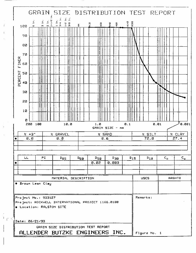
General excavation activities conducted at the borrow area included the removal, segregation,and stockpiling of clay material to be used in construction of the clay cap. Vegetative cover wassorted and removed from the surface layer of the borrow area to ensure that the cap would be freeof organic material. Soil material from the first borrow area (Borrow Area #1, Figure 1-2) wastested for permeability prior to the initiation of construction activities (Appendix A). Thepermeability test revealed that the material would be suitable for cap construction. The soil wastested once again when work began to confirm the suitability of the material. The results weregenerally consistent with the earlier test (Appendix A). Visual observations by personnel fromRockwell, Montgomery Watson, Westinghouse and CDM were utilized to determine the generalsuitability of the material stockpiled for placement on the cap.
Clay Cap Extension
Following the excavation and completion of general grading activities, an initial survey wasconducted to establish the boundaries of the cap and appropriate cut and fill elevations during theweek ending July 22, 1994. During this period, ash and debris were found to extend beyond theoriginal cap boundaries. Two additional excavation pits, 4 feet and 20 feet deep, were dug alongthe eastern edge of the proposed cap to further define the extent of buried ash at the site. OnJuly 25, 1994 Rockwell, Montgomery Watson and Westinghouse personnel determined that thecap would be extended to the east and to the south due to the presence of additional buried ashuncovered in these areas. Several small investigation trenches were dug to aid in determining theextent of the ash present.
Once the boundaries of the debris were adequately defined, the existing fence along the southernboundary of the site was moved further south approximately 8 feet to accommodate the cap

extension. Following the decision to extend the cap, additional grading activities wereconducted. After general grading elevations were established, the former disposal area wassurveyed again to define the base of the cap. While excavating the key-in zones on the western
s edge of the cap, additional ash and scrap metal debris were encountered in this area. FollowingI this discovery, the decision was made by Rockwell to extend the western edge of the cap, and
small investigation trenches were used to define the extent of debris. The key-in zones were: constructed once the cap extension was completed.
Buried Drums
i On July 26, 1994, during completion of the general grading activities at the eastern edge of thecap, six concrete-encapsulated drums were unearthed. One of the drums broke open andimmediately was overpacked along with the surrounding soil. No release to the environmentoccurred. The others subsequently were overpacked and all six drums were stockpiled in apolyethylene lined, bermed containment area in the southwestern corner of the Ralston site.
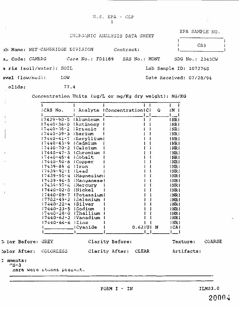
< Eleven composite soil samples were collected on July 26 and 27, 1994 from the area where the• drums were unearthed, and results confirmed that a release to the environment had not occurred* _
(Appendix B). The results of these analyses were later rejected by the S-Cubed Division of• Maxwell, an independent data validation consulting firm, due to unacceptable matrix spike\ recoveries. On July 27, 1994, an empty broken drum was discovered in the area of the eastern
cap extension. On August 3, 1994 one additional concrete-encapsulated drum was discovered, atI the top of the creek bank, in the central portion of the site. These two additional drums werei overpacked and stockpiled with the other drums in the southwest corner of the Ralston site.
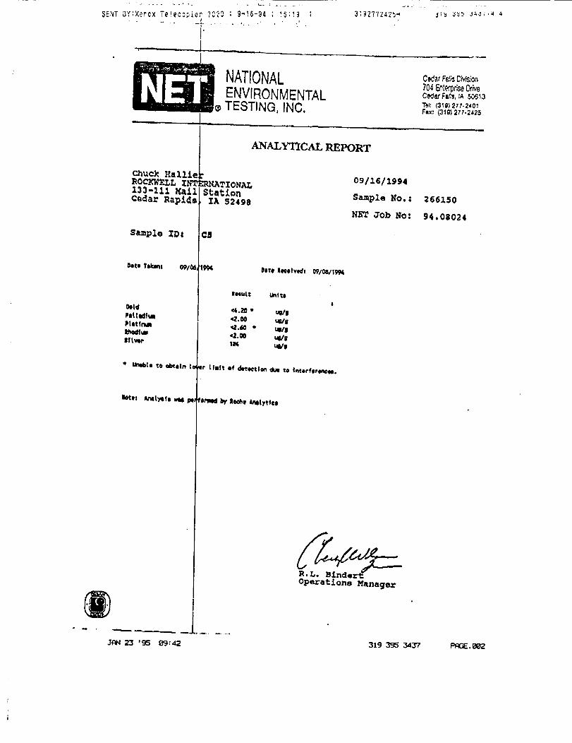
; Four grab samples were collected from the drummed material and analyzed for precious metals,• but no precious metals were detected in any of the samples (Appendix C). No additional analysis
was performed. Under the original hazardous waste profile for the site, the overpacked drums' were transported, by APTUS, to the APTUS disposal facility in Lakeville, Minnesota.1
CLAY CAP CONSTRUCTION
Placement of Clay
I A total of six lifts were placed to complete the clay cap according to the RAWP specifications.j Each layer of the compacted clay cap was completed by constructing a 4-inch lift of clay using
earth moving equipment. Montgomery Watson personnel provided necessary survey control to| maintain consistent 4-inch lifts. While placing each lift of the compacted clay cap, the contractori utilized a vibrating sheep's foot roller to achieve the necessary requirement of at least 95 percent
compaction. Before the sixth lift was placed, suitable material from the first borrow area was; depleted. Material from a second borrow area (Borrow Area #2, Figure 1-2) was used to1 complete approximately the last 1/4 of the sixth lift on the clay cap. Results of soil permeability
tests, performed on material from the second borrow area, confirmed the suitability of thej material and are included as Appendix D. Placement of the cap was completed on August 24,i 1994.
i Soil Testing Procedures
For purposes of verifying the permeability of the clay cap, the area was divided into five sections(Figure 2-1). This allowed soil testing to be tracked at a frequency of at least two field density

IIIIIIIIIIIE
MONTGOMERY WATSON
UONITORIHC WELL
SO/1. T£ST LOCATION
KEY:
SECTION 5—| |—LIFT 4ir5-4
ROCKWELL INTERNATIONAL CORPORATION
SOIL TESTINGLOCATIONS
FIGURE 2-1
tests per lift, as required in the RAWP, and ensured adequate spatial variance in testing locations.Testing locations were randomly selected by Montgomery Watson and COM personnel and arepresented according to section and lift numbers in Figure 2-1. Field density tests were conductedby Terracon Consultants, Inc. of Cedar Rapids, Iowa. Field testing was achieved bymechanically scraping off the upper inch of each lift from the test area to provide a smooth gradefor testing. Density tests were then performed using a Campbell Pacific Nuclear (CPN) modelMC2 nuclear density meter. During construction activities, a total of 18 field density tests wereperformed as documented in Table 2-1 and Appendix E. A minimum of two passing tests wereachieved per lift before construction commenced on the following lift. An individual test wasconsidered passing if the result indicated a minimum of 95 percent compaction had beenachieved.
Monitoring Well Extensions
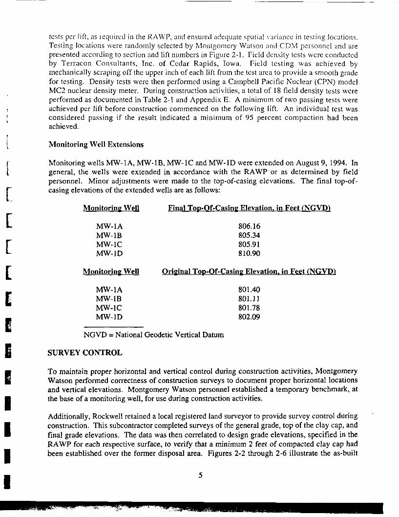
Monitoring wells MW-1A, MW-1B, MW-1C and MW-1D were extended on August 9, 1994. Ingeneral, the wells were extended in accordance with the RAWP or as determined by fieldpersonnel. Minor adjustments were made to the top-of-casing elevations. The final top-of-casing elevations of the extended wells are as follows:
Monitoring Well
MW-1AMW-1BMW-1CMW-1D
Monitoring Well
MW-1AMW-1BMW-1CMW-1D
NGVD = National Geodetic Vertical Datum
Final Top-Qf-Casing Elevation, in Feet (NGVD)
806.16805.34805.91810.90
Original Too-Of-Casing Elevation, in Feet (NGVD)
801.40801.11801.78802.09
SURVEY CONTROL
To maintain proper horizontal and vertical control during construction activities, MontgomeryWatson performed correctness of construction surveys to document proper horizontal locationsand vertical elevations. Montgomery Watson personnel established a temporary benchmark, atthe base of a monitoring well, for use during construction activities.
Additionally, Rockwell retained a local registered land surveyor to provide survey control duringconstruction. This subcontractor completed surveys of the general grade, top of the clay cap, andfinal grade elevations. The data was then correlated to design grade elevations, specified in theRAWP for each respective surface, to verify that a minimum 2 feet of compacted clay cap hadbeen established over the former disposal area. Figures 2-2 through 2-6 illustrate the as-built
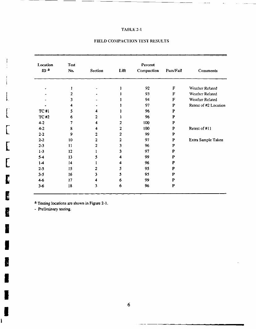
TABLE 2-1
FIELD COMPACTION TEST RESULTS
eiiiiii
Locationroa
-..
TC#1TC#24-24-22-22-22-31-35-41-42-53-54-63-6
TestNo.
123456789
101112131415161718
Section
---42442221512343
Lift
111111222233445566
PercentCompaction
929394979696
10010099979697999695959996
Pass/Fail
FFFPPPPPPPPPPPPPPP
Comments
Weather RelatedWeather RelatedWeather RelatedRetest of #2 Location
Retestof#ll
Extra Sample Taken
a Testing locations are shown in Figure 2-1.- Preliminary testing.

IIIIIIIIIIIIIII1III
MONTGOMERY WATSON
LEGEND:
• UOHlTORlNG WELL
MOTES:
I. X • ELEVATION IH FEET INGVDI
z. ALL ELEVATIONS GIVEN DENOTETO OF GENERAL FILL.
ROCKWELL INTERNATIONAL CORPORATION
GENERAL GRADING
V FIGURE 2-2

III1IIIIIIIIIIIIII
CABLE-STATED COMCftETS
MONTGOMERY WATSON
J
LEGEND:
• HONlTORING HELL
HOTES:
I. X * ELEVATION IH FEET IHGVDI
2. ALL ELEVATIONS GIVEH DENOTE TOPOF CLAf CAP.
ROCKWELL INTERNATIONAL CORPORATION
CAP GRADINGFIGURE 2-3
\

o so
SCALE IH F££T
LEGEND:
• MONITORING WELL
MOTES:
'• x • ELEVATIOH in FEET
2. ALL ELEVAT/OHS GIVEH DENOTE TOPOF FINAL GRADING.
ROCKWELL INTERNATIONAL CORPORATION
FINAL GRADINGMONTGOMERY WATSON

ii
MONTGOMERY WATSON
(.EGEW:
• HONITORING WELL
A A1CflOSS SECTION LOCATIONS
ROCKWELL INTERNATIONAL CORPORATION
CROSS SECTIONLOCATIONS
FIGURE 2-5

MONTGOMERY WATSON
120 160
DISTANCE IN FEET
CROSS SECTION A - A1
-UNCOUPACTED TOPSOIL
-COMPACTED CLAr
CABLED-STArED CONCRETE
to 10
DISTANCE IH FEET
CROSS SECTION B - ff
/•• 50'V.E.- I*
I"- 50'
ROCKWELL INTERNATIONAL CORPORATION
DISPOSAL AREA CAP:CREEK BANK STABILIZATION
CROSS SECTIONSA - A' AND B - B'
FIGURE 2-6

riE
iiiiii
elevations of the aforementioned layers of the cap and typical cross sections of the completedcap. The as-built elevations confirm that a minimum 2 feet of compacted clay cap was placed onthe former disposal area.
CREEK BANK STABILIZATION
Gabled-Concrete Mats
Royal Concrete Products (RCP) was subcontracted by Westinghouse to provide cabled-concretemats and to supervise their installation on the creek bank. To avoid intrusive anchoring throughthe geomembrane liner on the creek bank, alternative methods of anchoring the cabled-concretemats were explored. Personnel from Westinghouse, RCP and Montgomery Watson discussedalternative anchoring options and found that nonintrusive anchoring could be accomplished byadding additional mats at the top of the bank to balance those placed on the bank slope. Themats then would be anchored sufficiently at the top of the bank with anchors specified by RCP.Rockwell favored this alternative, so RCP designed the cabled-concrete mats to be placed in thismanner. As directed by site contractors and Rockwell, additional clay material was added to thetop of the central portion and east end of the creek bank to increase the density of the soil forbetter anchoring of the geomembrane liner. Prior to placing the geomembrane liner,Westinghouse cleared and graded the creek bank to remove tree limbs and other organicmaterials, protruding scrap metal and trash. These materials were stockpiled and inspected byRockwell personnel for disposal in the municipal landfill.
At this time, site contractors also discussed alternative creek crossing designs with Rockwell. Arevised design, which incorporated the use of RCP cabled-concrete mats, was provided toRockwell (Figure 2-7). Because the cabled-concrete mats provide a more substantial resistanceto erosion from creek flow, the revised design was implemented.
The additional soil placed on the top and sides of the creek bank, and the redesigned extension ofthe cabled concrete above the top of the creek bank, resulted in the placement of considerablymore material (geomembrane liner and cabled concrete) along the creek bank than was specifiedin the RAWP. A total of 13,400 square feet of geomembrane liner and 17,840 square feet ofcable-concrete mats were placed on the creek bank. The placement of additional materialenhanced, but did not alter, the functionality of the creek bank stabilization.
Westinghouse personnel installed the cabled-concrete mat system, including the construction ofthe revised creek crossing, under the supervision of RCP personnel during the week endingSeptember 23, 1994. Anchoring was conducted in accordance with recommendations from RCPpersonnel. As-built drawings of the geomembrane liner and cabled concrete installation areincluded as Appendices F and G, respectively.
Geomembrane Liner
Geo-Synthetics, Inc. (GSI) was subcontracted, by Westinghouse, to provide the geomembraneliner and to assist in its installation. The liner materials, supplied by GSI, were reviewed byMontgomery Watson personnel and met the RAWP specifications. Westinghouse and GSIpersonnel installed the geomembrane liner during the week ending September 10, 1994.

SC4/£- /AT FEET
CONCRETE UAT 5Y5TEU FOR ACCESS ROAOWAS INSTALLED SUCH THAT VEHICLESMAY USE THE ACCESS ROAO TO CROSSRUN CREEK. THIS INVOLVED MINIMALDEGRADING OF THE CREEKBED SO THATBOTTOM OF THE CREEK WAS UN/FORM.
HITS ran jcccis vto4-n , ifi. M t.yr .**T$ FOA *CCfiS/* HtTnC SOIL 4 O&Trt Of 4 >*CHC1
ROCKWELL INTERNATIONAL CORPORATION
DRY RUNCREEK CROSSING
MONTGOMERY WATSON

[L[[[
Placement of the liner and f ie ld testing of seams were conducted in accordance wi th the RAWP.Copies of the field tests are included as Appendix H.
DRAINAGE CONTROL
Construction of Terraces, Drainage Channels and Temporary Access Road
The terraces, drainage channels and temporary access road were constructed under thesupervision of Rockwell personnel. The approximate as-built locations of these constructioncomponents are included in Figure 2-8. The temporary access road was separated from the capby a filter fabric and was constructed using a 2-inch roadstone base overlaid by 1-inch roadstone.An October 21, 1994 review by Montgomery Watson personnel verified that the completeddrainage channels, terraces, and access road were constructed in general accordance with theRAWP. The post and rail barrier, placed along the access road at the bottom of the site entrance,was completed on December 20, 1994 following the construction review.
Seeding
Topsoil placement was conducted under the supervision of Rockwell personnel. Once finalgrading of the topsoil was completed, a final survey of the site, conducted by a local registeredsurveyor, confirmed that 2 feet of topsoil had been placed on the cap. Westinghouse retained asubcontractor to seed, fertilize and mulch the site following finish grading. Areas which receivedseeding included all disturbed areas within the former disposal and borrow areas. The seed mixplaced over these areas consisted of the following:
• Cap Only (per acre amounts)
2 Pounds Plains Coreopsis2 Pounds Black Eyed Susan2 Pounds Purple Cone Flower15 Pounds Little Blue Stem15 Pounds Sideoats10 Pounds Bluegramma50 Pounds Annual Rye400 Pounds 13-13-13 fertilizer
• Cap and Borrow Areas (per acre amounts)
25 Pounds Brome5 Pounds Alfalfa5 Pounds Birdsfoot20 Pounds Ky 311 Bag Oats400 Pounds 13-13-13 Fertilizer
The grasses were unable to sprout before winter because the site was not seeded untilOctober 20, 1994.

II
CAQL£-S~*r£D CO*C«T£
MONTGOMERY WATSON
NOTE:
i. ALL AREAS DISTURBED DURING COHSTHUCT/OHSEEDED ACCORDING TO SPECIFICATIONS.
ROCKWELL INTERNATIONAL CORPORATION
EROSION CONTROLFIGURE 2-6

OPERATION AND MAINTENANCE
Annual visual inspections will be conducted to check for breaches in the clay cap's integrity.Signs of erosion, cracks in the cap, rodents and other intrusions will be noted, and repairs will beconducted accordingly. A stormwater pollution prevention plan for the site is currently beingprepared and will be submitted at a later date under separate cover.
SUMMARY
Construction of the clay cap and creek bank stabilization was completed during the week endingDecember 24, 1994. The project generally was constructed in accordance with the RAWP;minor deviations from the Work Plan were as noted in Section 2. Figures 1 through 13 ofAppendix I present an appropriately labeled photo log of the finished work at the site.

APPENDIX A
-MONTGOMERY WATSON •

^LLENDER BUTZKE ENGINEERS INC.GEOTECHNICAL • ENVIRONMENTAL • CONSTRUCTION Q C.
Montgomery Watson June 28, 1993Attn: Jeffrey L. Coon, P.E.11107 Aurora AvenueDes Moines, Iowa 50322-7938 ,,.. n
JUL ° ' tS93Re: Laboratory Soil Analysis
Project 1166.0180Rockwell International - Ralston SitePN 933127
Dear Mr. Coon:
Enclosed are the results of Standard Proctor compaction, grain size distribution, andfalling head permeability tests performed on a potential soil liner sample submitted fromRockwell International Ralston Site. The soils submitted consisted of a bulk disturbedsample delivered on June 11, 1993.
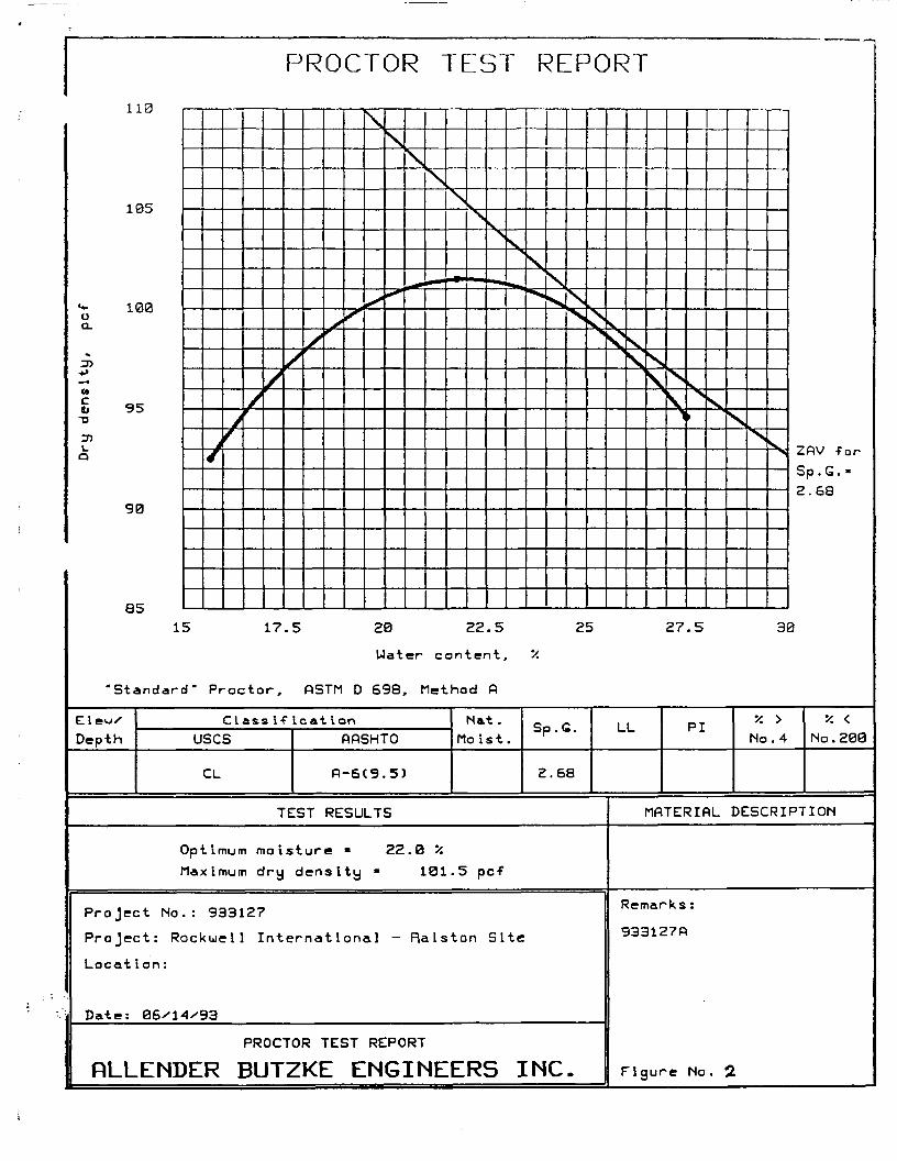
A Standard Proctor (ASTM D698) test was conducted on a representative soil sampleto evaluate compaction characteristics. A grain size test was also conducted on the soilsample. Results of the grain size and Standard Proctor tests are presented on the enclosedFigure Nos. 1 and 2.
Permeability characteristics of the potential soil liner sample was evaluated byconducting a falling head permeability test on soil remolded near 2 percent above optimummoisture content and compacted to approximately 91 percent of the determined maximumdry density. The remolded sample was 6 inches in length and the permeability test wasconducted by passing water through the soil sample under water heads ranging from 6 to 10feet The results of the falling head permeability test are provided on the following TableA.
If there are any questions concerning these test results, please contact us at yourconvenience.
Respectfully
ALLENDER BUTZKE ENGINEERS, INCDL/sjd2 PC Above
David Logemann, P.E.
3100 JUSTIN DRIVE, SUITE F • URBANDALE, IOWA 50322 • PHONE 515-252-1885 • FAX 515-252-1888

TAB LEA
LABORATORY SOIL TESTING SUMMARYROCKWELL INTERNATIONAL PROJECT 1166.0180
PN 933127
SampleDesignation
Ralston
Optimum ..;.'.Moisture <
; Content ::::(percent)
22.0
Maximum•:•••:-. Dry. :.?-:;;; Density :
^-•(pc9::^:101.5
RemoldedMoisture
;^;:Content;;:,-:"(percent)^
23.6
Remolded;::;Dry Density
m^(pcf)m.^
92.5
PercentGompaclibn
91.1
Permeability.: cmTsec;:;,:/,,:,. ::::::;.::::X;:.:;;;V :;,;.;,
4.0 x lO*
ALLENDER BUTZKE ENGINEERS INC
•
•
I
100
90
80
70Of.LJ
S 60U.
Z 50LJLJ
LJ 40D_
30
20
10
02E
3RHIN.SIZE DISTRIBUTION TEST REPORTc
c c cC. C C \ C Q C3
10 m oj •"• ~« rn -* ni ^ ^ * ^ •* •* 4*
10
TI\N
XHS ss ^^
•^ .
100 10.0 1.0 0.1 B.01 ^^0.001GROIN SIZE - mm ^^
X +3"0.0
LL
'/. GRflVEL0.0
'/. SftND0.6
'/. SILT72.0
V. CLflY27.4
PI DBS D60 D500.02
D300.003
D15
MATERIAL DESCRIPTION
• Broun Lean Clay
Project No. : 933127Project: ROCKUELL INTERNATIONAL PROJECT 1166.01B0
• Location: RALSTON SITE
Date: 06/21/93
GRftIN SIZE DISTRIBUTION TEST REPORT
RLLENDER BUTZKE ENGINEERS INC.
D10
uses
cc cu
ftASHTO
Remarks :
Figure No. 1
110
105
«+• 100uQ.
^DJ*»
C4
£ 9-D
:nLa
9
e
•st«Clew/Depth
5
0
51
sndari
PROCTOR TEST REPORT
///'/X
5 17.
i" Proctor,
Class ifusesCL
X
XwS
\
^
\
^
\
•*i
\
•
N
>»
k.
S
i H
S
«•*
S
*••
\\
•%vj\N s \ ssstsskV\
\Vsss, ZfiV ^or
Sp.G.-2.68
5 20 22.5 25 27.5 30
Hater content, *
OSTM D 698, Method fi
Icat ionfifiSHTO
R-6C9.5)
Nat.Moist.
Sp.G.
2.68
LL
TEST RESULTS
Optimum moisture » 22.0 /£Maximum dry density • 101.5 pcf
Project No. : 933127Project: Rockwell International - Ralston Site
Locat Ion :
Date: 06x14x93
PROCTOR TEST REPORT
RLLENDER BUTZKE ENGINEERS INC.
PI y. > •/. <No . 4 No . 293
MATERIAL DESCRIPTION
Remarks :
933127ft
Figure No. 2

CONSULTANTS, INC.
P 0 Bet t-Cecar Pac.cs c^a 52-C6-25c7
4, 1994 -Si* 3ee.a32- Fa. - 3 - 9 : 266-OC32
La r ' / •< Ca-.:C = cn =EDe.nns E v.'-xed. PEAndre V Guiles. P£
• Timc'~'y T '.V>!es. P£T^c^as A Sa;mWestinghouse Remediation Services, Inc.
21750 Cedar AvenuePO Box 550Lakeville, MN 55044
Attention: Mr. Mark Gunderson
Re: Laboratory TestingSoil Cap at Rockwell on Collins RoadCedar Rapids, IowaJob No. 06941077
Dear Mark:
The purpose of this letter is to provide the results of therequested laboratory soils testing for the above project. Thefollowing sections provide the test results or reference theattached graphs 'and tables as necessary.
Standard Proctor Compaction Test
One standard Proctor compaction test was performed in accordancewith ASTM D-698. The moisture/density relationship and testresults are attached.
Hydraulic Conductivity
Two hydraulic conductivity tests were performed in generalaccordance with ASTM D5084 on samples that were compacted in ourlaboratory. The results of these tests are tabulated below.
Sample
90
96
InitialDryDensity
f DCf )
98.1
104.9
InitialMoistureContent(%)
19.8
19.8
Percentof MaximumDry Density
90
96
HydraulicConductivity( cm/sec. )
2.2 X 10"7
1.2 X 10"'
Offices of The Terracon Companies. Inc. Geotechnical. Environmental and Materials EngineersArizona Tucson • Arkansas Sonngdale • Colorado Colorado Sonngs Denver Ft Co»ins Greeiey. longmont
• laano Boise • Illinois Bloommgton. Chicago Rock Island • Iowa Ceoa' Fans. Cedar Rao-ds Davenoon. Des Momes.Siorm Lake • Kansas Lerexa. Toceka Wich'ta • Minnesota St Paul • Missouri Kansas C.ty
• Netya>*a 1'i'com Gmana • Nevada Las Vegas • Okianoma Ckiancma City. Tuisa • Texas Dallas• 'JUh Sail Lake City • Wyoming Cneyenne
QUALITY ENGINEERING SINCE 1965

Job No. 05941077Augus t 4 , 1994Page 2 , -racon
In summary, the sample compacted to 90% of the maximum drydensity did not meet the permeability specification of 1 X 10"cm/sec., and the sample compacted to 96% of the maximum did meetthis specification.
Specific Gravity
The specific gravity was computed based on the moisture contentof hydraulic test specimen 96 after testing (saturated). Thespecific gravity was determined to be 2.54.
Plastic and Liquid Limits
The liquid limit, plastic limit, and plasticity index weredetermined in accordance with ASTM D4318. The results of thesetests are shown on the attached Atterberg Limits Result sheet.
Grain Size Analyses
One grain size test, including sieve and hydrometer analyses inaccordance with ASTM D433, was performed. We have includedgrain size curves as well as tabulated results for theseanalyses.
If you have any questions concerning these results, or if we canbe of any further service, please do not hesitate to contact us.
Very truly yours,
TERRACON CONSULTANTS, INC.
Timothy T. Wiles, P.E.Iowa No. 12939
TTW/amd
Attachments

135
130
125
120
o&.a3Oh.oOL
•a
oa.
tnzaiO
DCa
110
105
100
95
90
85
80
75
'lien
11
11
\ \\ l\-Ai
1
\\—
H\
ii1i
i
1
1
\\\\\\
\\\\\
i
MOISTURE-DENSITY RELATIONSHIPJobNo 06941077 Date 7/18/94
\
Project
^ \\l '
t-V\V \\ \i\
t*
/f
v
\^
/
Rockwel l Soil Cap
Source of Material
Description of Materic
V\
\\
\\\
\
/
\\
/
Material Des
Test Method
\
\
\
\
s
y\
\\
X
\X
\\
\Si
^vX
^
sX
X
\'s,
\^X
\
Xs
V. sss
ignation
AST
yx\X
1
,i Brown Lean Clay, Trace Sand
M D-698 (Method A)
TEMaximum Dry
Optimum V\
\\
^s^s
\x
V
xN\vx^s
\\x
Kv.^
Vss
1ST RESULTSDensity 109.0 PCF
teter Content 17.0 %
CURVES OF 100% SATURATIONFOR SPECIFIC GRAVITY EQUAL TO:
. , _____ 2.80\
\y
S
i\/ ———— 2 7°ji. .- 260x ^Vj<C\.A ^k.
N-^X Ckv ^ V^ ^AX XX
^ \V \ V
V ^ 5v
^S !^V \
Vk_\ '\.> \l \.
V. ]\ 1VxN.^
10 15 20 25 30 35 40 45
WATER CONTENT (Percent Dry Weight)
Form 122

50
Mo.- 40xLdaM
MOM
CO
30
10
CL-ML /
• S
/
CL
/
/
ML
CH
^
MH
/
x
X
Xy
10 20 30 40 50 60 70 80 90 100 11
BORING DEPTH1.0
LIQUID LIMIT <LL>
LL PL_ PI CLASSIFICATION34 20 14 CL
r August 1994
WESTINGHODSE REMEDIATION - CEDAR RAPIDS, IOWA -
ATTERBERG LIMITS RESULTS
Terracon Consultants/ Inc.

<^_
U.S. Standard Sieve
100. ,3 * " /»13/«
90 -
80 -
4-•C 7n0> '0 -0)
_ (O -31 "".Q
« so-ilt «°-<uu« 30-
OL
20-
10-
0.100
BoringNo.
• 0
Openings in InchesV23,o * a1
U.S. St
J 16 2(
1 ——— — = =
andt
' 3(= s
rd
)
S40
=«
iev<
5("**«.
s Numbers Hydrometer
J60 100 U° 200 27°
--•«.~~^— _v
S\
\\\i
\
\ [
\\
\
i*„« " *
• ^^_^^
0
10
20+-
30 ."§flj2
AO >
L01
50 UJinou
60 ^cCLJu
70 bCL
80
90
10010 1 0.1 0.01 0.001
Grain Size in Mil l imetersGRAVEL
Coarse I
SampleNo.
Project
Depth
1.0
FineSAND
Coarse Medium FineSILT or CLAY
GRAIN SIZE DISTRIBUTION CURVE
Description
LEAN CLAY
UnifiedSymbol
CL
NaturalUC LL
34
PL PI
20 U
WESTINGHOUSE REMEDIATION - CEDAR RAPIDS, IOWA -
Job No. 06941077 Date 8 /4 /94 "I Terr aeon _

APPENDIX B
-MONTGOMERY WATSON •

U.S. EPA - CLP1
INORGANIC ANALYSIS DATA SHEETEPA SAMPLE NO.
CS1iD Name: NET-CAMBRIDGE DIVISION Contract: I_________
-: Code: CAMBRG Case No.: FD1189 SAS No.: MONT SDG No.: 2343CW
itrix (soil/water): SOIL Lab Sample ID: 107274S
? 3l (low/med): LOW Date Received: 07/28/94colids: 83.2
Concentration Units (ug/'L or mg/Kg dry weight): MG/KG
CA5 Mo.
7429-90-57440-36-07440-36-27440-39-37440-41-77440-43-97440-70-27440-47-37440-4G-47440-50-87439-G9- 67439-92-17-139-95-47439-96-57-i39-97-67440-02-07440-09-77732-49-27440-22-47440-23-57440-28-07440-62-27440-66-6
11 Analyte11 Aluminum1 AntimonyI Arsenic1 Barium(Beryllium1 Cadmium1 Calcium1 Chromium1 Cobalt1 Copper1 1 ron1 Lead1 Magnesium1 Manganesei Mercury1 Nickel1 Potass ium1 Selenium1 SilverISodiumIThallium1 Vanadium1 Zinc1 Cyanide1
Concentration
0.60
C
U
1 1Q IM 1
1 1INRIINRIINRIINRIINRIINRIINRIINRIINRIINRIINRIINRIINRIINRIINRIINRIINRIINRIINRIINRIINRIINRIINRI
1 N ICAI1 1 1
"olor Before: GRtif
"tlor After: COLORLESS
Clarity Before:
Clarity After: CLEAR
nments:CS-1here vere stones and pieces of metal present.
Texture: COARSE
Artifacts: YES
FORM I - IN ILM03.0
2000;:

U.S. EPA - CLPL
INORGANIC ANALYSIS DATA SHEET
-.b Name: NET-CAMBRIDGE DIVISION Contract:
4' Code: CAMERG Case No.: FD11S9 SAS No.: MONT
E?A SAMPLE NO,
CS2
(soil/water): SOIL
ivel (low/med): LOW
SDG No.: 2343CW
Lab Sample ID: 107275S
Date Received: 07/28/94
alids 71.9
Concentration Units (ug/'L or mg/Kg dry weight): MG/KG
11C A3 No.I17429-90-5! 7440- 36-0i 7440-36- 2i 7440-39-317440-41-717440-43 -917440-70-2i 7440-47-317440-43-417440-50-8i 74J9-G9-6i74J9-92-ii 7439-95-41 7-139- 96-5i 7439-97- t.17440-02-0I 7440-09-717782-49-217440-22-417440-23-517440-26-017440-62-21 7440-66-011
1i Analyta1i Aluminum1 Antimonyi Al" SettlCIBariuin1 Berylliumf Cadmium1 Calcium1 ChromiumI Cobalt1 Copper1 IronILead1 Magnesium1 Manganese1 Mercury1 Nickel(Potassium1 Selenium(Silver1 Sodiumi Thallium[Vanadium1 Zinci Cyanide1
Concentration C1 1
Q IM 11 1INRIINRIINRIINRIINRIINRIINRIINRIINRIINRIINRIINRIINRIINRIINRIINRIINRIINRIINRIINRIINRIINRIINRI
0.69IUI N ICAII I I I
< ".or Before: GREY
:olor After: COLORLESS
Clarity Before:
Clarity After: CLEAR
".< nments:CS-2
lere wens sr.omss and pieces of metal present.
Texture:
Artifacts: YES
FORM I - IN ILM03.02000
U.S. - CLP
INORGANIC ANALYSIS DATA SHEET
ab Name: NET-CAMBRIDGE DIVISION Contract:
EPA SAMPLE NO,
CS3
a.. Code: CAMBRG Case No.
a rix (soil/water): SOIL
avel (low/n'iedi : LOW
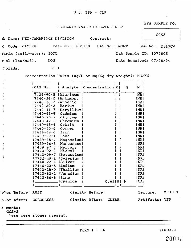
olids: 77.4
FD1189 SAS No.: MONT SDG No.: 2343CW
Lab Sample ID: 107276S
Date Received: 07/28/94
Concentration Units (ug/L or mg/Kg dry weight): MG/KG
lor Before: GREY
After: COLORLESS
nments:•"5-3nere weir; i, tones, pi
Clarity Before:
Clarity After: CLEAR
1!CA3 No.i17429-90-517440-36-0i 7440-38-217440-39-317440-41-717440-43-9! 7440-70-2J7440-47--317440-46-417440 -50 -a17439-89 o17439-92-117439-95-417439-96-5i 7439- 97- ei17440-02-017440-09-717782-49-217440-22-417440-23-517440-28-017440-62-217440-66-611
11 Analyte11 Aluminum1 Antimony1 Arsenici Barium(Beryllium1 Cadmium1 Calcium1 Chromiumi Cobalt1 Copper1 IronILead[Magnesiumi Manganesei MercuryI Nickel1 Potassiumi SeleniumISilver1 Sodiumi Thallium(Vanadiumi Zinc1 Cyanide1
Concentration
0.62
C
U
1Q IM
1INRINRINRIINRIINRIiNRIINRIINRIINRIINRIINRIINRIINRIINRIINRIINRIINRIINRIINRIINRIINRIINRIINRI
I N ICAI1 1 1
Texture: COARSE
Artifacts:
FORM I - IN ILM03.0
20004

U.S. EPA - CLP1
INORGANIC ANALYSIS DATA SHEETEPA SAMPLE NO.
I CS4Name: NET-CAHr.KlDGE DIVISION Contract:
c . Code: CAM3RG
c ''.rlx C soil /water ) :
evel (low/med):
Solids:
Case No
SOIL
LOW
82.8
FD1189 SAS No.: MONT SDG No.: 2343CW
Lab Sample ID: 107277S
Date Received: 07/28/94
Concentration Units (ucj/'L or mg/Kg dry weight): MG/KG
11 CA3 No.j17429-90-51 7440-36-017440-38-217440-39-317440-41-717440-43-917440-70-2! 7440-47-3i 7440-48 -41 7440-50-6i 7433-39-6i 7439-92- i1743-5-95-41 7439- 96-517439-97-617440-02-017440-09-717782-49-217440-22-417440-23-517*40-28-017440-62-217440-66-61i
Analyte
AluminumAntimonyArsenicBariumBerylliumCadmiumCalciumChromiumCobaltCopperIronL"ra'..lMagnesiumManganeseMercuryNickelPotassium~»eieniumSilverSodiumThalliumVanadiumZincCyanide
Concentration
0.57
C
IU1
I |Q IK 1
1 1INRIINRIINRIINRIINRIINRIINRIINRIINRIINRIINRIINRIINRIINRIINRIINRIINRIINRIINRIINRIINRIINRIINRI
I N ICAI1 1 1
1 lor Before: GRuiY
^olor After: COLORLESS
Clarity Before:
Clarity After: CLEAR
mments:CS-4here were oi*y and root.i present.
Texture: COARSE
Artifacts: YES
FORM I - IN ILM03.0
2000^

U.S. c.PA - CLP1
C ANALYSIS DATA SHEETEPA SAMPLE NO.
CS5.b Name: NET-CAMBRIDGE. DIVISION Contract: I____________
I Code: CAM3RG Case No.: FD1189 SAS No.: MONT SDG No.: 2343CW
:t-rix (soil/water): SOIL Lab Sample ID: 107278S
.-Veil (low/med): LOW Date Received: 07/28/94
£ .lids: 34.0
Concentration Units, (ug/L or mg/Kg dry weight): MG/KG
iICAS No.I17429-90-517440-36-0i 7-i40-36-21 744G-39--317440-41-717440-43-917440-70-2i 7440-47- 317440-40-417440-50-8I 7439-09-617439-92-11 7439-95 -4i 7439-96-5i 7439-97-617440-02-0i 7440-09-7i 7762-49-217440-22-417440-23-517440-23-017440-62-217440-66-611
11 Analyte11 Aluminum1 Antimony1 ArsenicIBai ium(Berylliumi Oadifiium1 Calcium1 Chromium1 Cobalti Coopfer1 Iron1 Lead1 Magnesium1 Manganese(Mercury11-JickelIPotassiumi Selenium1 Silver1 £>od5um1 Thallium1 Vanadium1 Z inc1 Cyanide1
Concentration
0.57
C
U
1 1Q IM 1
1 1INRIINRIINRIINRIINRIINRIINRIINRIINRIINRIINRIINRIINRIINRIINRIINRIINRIINRIINRIINRIINRIINRIINRI
N ICAI1 1
o^or Before: RUST
oior After: COLORLESS
c ments:
sre were stones and
Clarity Before:
Clarity After: CLEAR
i&6 present.
Texture: COARSE
Artifacts: YES
FORM I - IN ILM03.020006

U.S. - CL,P
INORGANIC ANALYSIS DATA SHEET
-.b Name: NET-CAMBRIDGE DIVISION Contract:
EPA SAMPLE NO.
I CS6
Code: CAMBRG Case No.
(soil/water): SOIL
e 1 (low/med} : LOW
olids: S4.3
FD1189 SA3 No.: MONT SDG No.: 2343CW
Lab Sample ID: 107698S
Date Received: 08/04/94
Concentration Units (ug/L or mg/Kg dry weight): MG/KG
i 1ICA3 No. 1 Analyte1 117429-90-5 ! Aluminum17440-30-0 1 Antimonyi 7440-36-2 (Arsenic17440-39-3 1 Barium17440-41-7 IBeryllium17440-43-9 1 Cadmium17440-70-2 ICalcium17440-47-3 1 Chromium17440-46-4 I Cobalt17440-50-8 I Copper17439-6'7-tj 1 Ironi 74"; 3-92- L iL«ad17439-95-4 IHaonesium17439-96-5 IManganesei 7439- 97-6 ll-fercury17440-02-0 iNickel17440-09-7 IPotassium! 7762-49-2 1 Selenium.! 7<i40-22-4 ISilver17440-23-5 ISodium17440-26-0 (Thallium17440-62-2 (Vanadiumi 7440-66-6 IZiric• ICvanide1 1
Concentration
0.59
C
U
i 1Q IM 1
1 1INRIINRIINRIINRIINRIINRIINRIINRIINRIINRIINRIINRIINRIINRIINRIINRIINRIINRIINRIINRIINRIINRIINRI
1 N ICAI1 1
If lor Before: GR£.Y!olor After: COLOFiEGS
Clarity Before:
Clarity After: CLEAR
nments :CS-6
were atones, and ioot.s present in the sample.
Texture; MEDIUM
Artifacts: YES
FORM I - IN ILM03.0
200U

U.S. EPA - CLP1
INORGANIC ANALYSIS DATA SHEETEPA SAMPLE NO.
I DRUMMATab Name: NET-CAMBRIDGE DIVISION Contract: I____________
a Code: CAMBRG Case No.: FD1189 SAS No.: MONT SDG No.: 2343CW
a-»-rix (soil/water): SOIL Lab Sample ID: 107283S
evel (low/med): LOW Date Received: 07/28/94
79.0
Concentration Units (ug/L or mg/'Kg dry weight): MG/KG
i IICAS No. { Analyte! 17429-90-5 (Aluminum7440-36-0 1 Antimony7440-38-2 1 Arsenic7440-39-3 IBarium7440-41-7 1 Beryllium7440-43-9 1 Cadmium7440-70-2 ICalcium7440-47-3 1 Chromium7440-43-4 i Cobalt7440-50-8 (Copper7439-89-6 i Iron7439-92-1 ILead7439-95-4 (Magnesium7439-96-5 1 Manganese7439-97-6 I Mercury7440-02-0 1 Nickel7440-09-7 1 Potassium7732-49-2 i Selenium7440-22-4 ISilver7440-23-5 ISodium7-i4G-26-0 1 Thallium7440-62-2 (Vanadium7440-66-6 (Zinc
iCvanide1
Concentration
0.61
C
~
U
1 1Q IM 1
1 1INRIINRIINRIINRIINRIINRIINRIINRIINRIINRIINRIINRIINRIINRIINRIINRIINRIINRIINRIINRIINRIINRIINRI
I N ICAI1 1 1
o"or Before: GREY
olor After: COLORLESS
z> nerits:ED MATERIAL
a^. ol-ay preser
Clarity Before:
Clarity After: CLEAR
Texture: FINE
Artifacts: YES
FORM I - IN ILM03.0
20011

U.S. EPA - CLP1
INORGANIC ANALYSIS DATA SHEET
,ab Name: NET-CAMBRIDGE DIVISION Contract:
.. :> Code: CAM3RG Case No.: FD1189 SAS No.: MONT
EPA SAMPLE NO.
CCS1
SDG No.: 2343CW
>trix (soil/water): SOIL
-ev/el (low/med): LOW
Lab Sample ID: 107279S
Date Received: 07/28/94
Solids: 02.3
Concentration Units (ug/L or mg/Kg dry weight): MG/KG
CAS No.
7429-90-57440-36-07440-38-27440-39-37440-41-77440-43-97440-70-27440-47-37440-48-47440-50-87439-89-67439-92-17439-95-47439-96-57439-97-67440-02-07440-09-77762-49-27440-22-47440-23-57440-28-07440-62-27440-66-6
Analyte
AluminumAntimonyArsenicBariumBerylliumCadmiumCalciumChromiumCobaltCopperIronLeadMagnesium(Manganese1 Mercury1 Nickel1 Potassium1 Selenium1 Silver1 Sodium1 Thallium1 Vanadium1 Zinc1 Cyanide1
Concentration
0.57
C
U
1 1Q IM 1
1 1INRIINRIINRIINRIINRIINRIINRIINRIINRIINRIINRIINRIINRIINRIINRIINRIINRIINRIINRIINRIINRIINRIINRI
1 N ICAI1 1 1
t~ >lor Before: GREY
Color After: COLORLESS
Clarity Before:
Clarity After: CLEAR
« jmments:ccs-iJhere were stones and glass present.
Texture: MEDIUM
Artifacts: YES
FORM I - IN ILM03.0
20DO'
U.S. EPA - CLP1
EPA SAMPLE MOINORGANIC ANALYSIS DATA SHEET
ib Name: NET-CAMBRIDGE DIVISION
j] Code: CAMBRG Case No.: FD1189
atrix (soil/water): SOIL
i- 3l (low/mad) : LOW
Contract:CCS 2
SAS No.: MONT SDG No.: 2343CW
Lab Sample ID: 107280S
Date Received: 07/28/94
Talids: 81.1
Concentration Units (ug/L or mg/Kg dry weight): MG/KG
1ICAS No.i17429-90-517440-36-017440-38-217440-39-317440-41-717440-43-917440-70-217440-47-317440-48-41 7440-50-817439-89-617439-92-117439-95-417439-96-517439-97-617440-02-017440-09-717782-49-217440-22-417440-23-517440-28-017440-62-217440-66-611
ii Analyte1[Aluminum1 Antimony1 Arsenic1 Barium(Beryllium1 Cadmium1 Calcium1 Chromium1 Cobalt1 Copper1 IronILead(Magnesium(Manganese1 Mercury1 Nickel1 Potassium(Selenium(Silver1 Sodium(Thallium1 Vanadium1 Zinc(Cyanide1
Concentration
0.61
C
U
1 1Q IM 1
1 IINRIINRIINRIINRIINRIINRIINRIINRIINRIINRIINRIINRIINRIINRIINRIINRIINRIINRIINRIINRIINRIINRIINRI
I N ICAI1 1 1
o"J or Before: RUST
Cj.or After: COLORLESS
Clarity Before:
Clarity After: CLEAR
'.c ments :CCS-2
were stones present.
Texture: MEDIUM
Artifacts: YES
FORM I - IN ILM03.0
20008

U.S. EPA -1
CLP
INORGANIC ANALYSIS DATA SHEETEPA SAMPLE NO.
CCS3ab Name: NET-0AMBRIBGE DIVISION Contract: I____________
• j Code: CAMBRG Case No.: FD1189 SAS No.: MONT SDG No.: 2343CW
(soil/water): SOIL Lab Sample ID: 107281S
(low/med): LOW Date Received: 07/28/94
solids: 81.8
Concentration Units (ug/L or mg/Kg dry weight): MG/KG
CAS No.
7429-90-57440-36-07440-36-27440-39-37440-41-77440-43-97440-70-27440-47-37440-48-47440-50-87439-89-67439-92-17439-95-47439-96-57439-97-67440-02-07440-09-77732-49-27440-22-47440-23-57440-28-07440-62-27440-66-6
11 Analyte11 Aluminum1 Antimony1 ArsenicIBariumIBeryllium1 CadmiumICalcium1 Chromium1 Cobalt1 Copper1 IronILead1 Magnesium(Manganese1 Mercury1 Nickel1 Potassium1 Selenium(Silver1 Sodium1 Thallium(Vanadium1 Zinc1 Cyanide1
Concentration
0.56
C
U
I 1Q IM 1
1 1INRIINRIINRIINRIINRIINRIINRIINRIINRIINRIINRIINRIINRIINRIINRIINRiINRIINRIINRIINRIINRIINRIINRI
I N ICAI1 1 1
" lor Before: RUST
]olor After: COLORLESS
Clarity Before:
Clarity After: CLEAR
mrcnents:OCS-3.'here were stones and roots present.
Texture: FINE
Artifacts: YES
FORM I - IN ILM03.0
2000

U.S. EPA - CLP1
INORGANIC ANALYSIS DATA SHEETEPA SAMPLE NO.
i I II CCS4 I
.ab Name: NET-CAMBRIDGE DIVISION Contract: I______________|
1 b Code: CAMBRG Case No.: FD1189 SAS No.: MONT SDG No.: 2343CW
•latrix (soil/water): SOIL Lab Sample ID: 107282S
I vel (low/rued): LOW Date Received: 07/28/94
* Solids: 37.9
Concentration Units (ug/L or mg/Kg dry weight): MG/KG
CAS No.
7429-90-57440-36-07440-38-27440-39-37440-41-77440-43-97440-70-27440-47-37440-43-47440-50-87439-89-67439-92- I7439-95-47439-96-57439-97-67440-02-07440-09-77782-49-27440-22-47440-23-57440-28-07440-62-27440-66-6
11 Analyte11 Aluminum[Antimony1 ArsenicIBarium(Beryllium1 Cadmium1 Calcium1 Chromium1 Cobalt,1 Copper1 Iron1 Lead(Magnesium(Manganese(Mercury1 Nickel(Potassium(Selenium(Silver(Sodium(Thallium(Vanadium1 Zinc(Cyanide1
Concentration C1 I
Q IM 11 1INRIINRIINRIINRIINRIINRIINRIINRIINRIINRIINRIINRIINRIINRIINRIINRIINRIINRIINRIINRIINRIINRIINRI
0.55IUI N ICAII I I I
Color Before: RUST
.olor After: COLORLESS
"omments:CCS-4There were stones present.
Clarity Before:
Clarity After: CLEAR
Texture: COARSE
Artifacts: YES
FORM I - IN ILM03.0
2001G

APPENDIX C
-MONTGOMERY WATSON •

MFTlilC.:!NATIONALENVIRONMENTAL
|« TESTING, INC.
Coda: Falls Divij'on7C4 Ertwprtw CriveC«(3ar Falls, IA SC613Tel: (31B)277-2<01Fax: (316)277-2423
ANALYTICAL REPORT
Chuck HallierROCKWELL INTERNATIONAL133-111 Hail iitationCedar Rapids,
Sample ID: !2
»•<• Tiktnt 09/06/' 994
tetd
XhodlwItlvtP
ZA 52498
(•cult Unfta
0.7U
<0.2M0.979
UO/t
uo/t
• Unablt t« «bt«<n l«*»r KMt of dvttettan Am to
Notts
09/16/1994
sample No.: 266147NET Job Ho: 94.08024
: 09/M/19M
Operations Manag«r
JflN 23 PSS 09:41 319 395 3437 PflGE.OTl

NATIONALENVIRONMENTALTESTING, ING.
Division704 Enterprise DrivaCedar Falls. IA 50613TV: (319) 3 77-2401F«: :3<9,'277-2*24
ANALYTICAL REPORT
ROCKWSLL INTERNATIONAL133-111 Mail stationCedar Rapids, IA 52498
Sample ID:
Bit* Tlkwu 0*/M/i«M
09/16/1994
Saapla No.: 266148
NET Job No: 94.08024
R.L, Bindert"Operations
JflN 23 '95 09:42 319 395 3437TOTflL P. 04PflGE.004

NET NATIONALENVIRONMENTAL
J® TESTING, INC.
Ceda; FaKs Division704 £nt«pris» DriveCecar Fails. IA 506137tt; (318)277-2*01F*x: (310)277-2425
ANALYTICAL REPORT
Chuck Hal liarROCKWELL INTERNATIONAL13-133-111 MailCedar Rapid*
Sample ID:
Cetd
H«tlnuiModlui
StationIA 52498
C4
•4.250<0.2M«0.2SO«.Z50O.210 •
0«tt t«ce{vtdt
unit*
"I/I<*/tug/i
br RodM
09/16/1994
saaple NO.J 266149NET Job No: 94.08024
R « L .Operations Manag«r
JflN 23 '95 09:42 319 395 3437 PPGE.003
SENT 3Y:Xcrox Telecopier 7220 : 3-16-94 ; <5:i9 '<
NETchuck Ha HiROCKWELL IN133-111 MaiCedar Rapid
INTERNATIONALStationXA 52498
Sample ZOt
8«t» Trtwtl 09/06,
• l*wbl« to cbtttn t
Anttytf* UM pi
NATIONALENVIRONMENTAL
}® TESTING, INC.
ANALYTICAL REPORT
C«?ar Fa!k Division704 Eniefprisa DriveCsdsr Fa/is. IA 50613•fti: (319)277-2<01
09/16/1994
Sample Ko.: 266150
NET Job Ko: 94.08024
ca
D»t« lf««lv«di Q9/08/19M
««ult unit*
«.20 • ug/g
«Z.M ua/9
«2.00IK U8/f
»r U.ft «f drtKtlon dm to tnt*rftr*neM.
Operations Manager
JflN 23 '95 09:42 319 395 3437 PflGE.002

APPENDIX D
-MONTGOMERY WATSON •

RECEIVED 1 (errsconSEP ~ 1 1994 CONSULTANTS, INC.
August 31 1994 MVV/IOWA ceAugust o J. , i y y 4 2:91 ze3e-a:c 3 Dison ?E-J'-y < Davicson ? =de-^is E .Vhned. ?E
. . . . . _ . . . . _ . _ incre M Gaiiet PEWestinghouse Remediation Services, Inc. -*c.-as A saim21750 Cedar AvenuePO Box 550Lakeville, MM 55044
Attention: Mr. Mark Gunderson
Re: Laboratory Testing - Borrow Area $2Soil Cap at Rockwell on Collins RoadCedar Rapids, IowaJob No. 06941077
Dear Mark:
The purpose of this letter is to provide the results of therequested laboratory soils testing for the above project. Thefollowing sections provide the test results or reference theattached graphs and tables as necessary.
Standard Proctor Compaction Test
One standard Proctor compaction test was performed in accordancewith ASTM D-698. The moisture/density relationship and testresults are attached.
Hydraulic Conductivity
Two hydraulic conductivity tests were performed in generalaccordance with ASTM D5084 on samples that were compacted in ourlaboratory. The results of these tests are tabulated below.
Sample
90
95
InitialDryDensityfpcf )
97.2
102.6
InitialMoistureContent(%)
20.1
20.1
Percentof MaximumDry Density
90
95
HydraulicConductivity( cm/sec. )
8.5 X 10"'
1.0 X 10~8
Offices of The Terraeon Companies. Inc. Geotechnical, Environmental and Materials EngineersArizona Tucson • Coioraoo Ccic-aao Sov-:gs Denver. F; Coilms. Greeiey longmom • idano 9&se • llhnccs Biccmmgion
O>cago Rock island • 'c«a Cedar -jus Cedar flao'ds. Oavenoon. Des Momes Storm Laxe • Kansas Leneia. Tooexaw.cnita • Minnesota 5: °a-i • Missouri Kansas City • Neorasu Lincoln Omana • Nevaea Las Vegas
• Olanoma OK:a"C"a City, 'usa • Texas Dallas • LKan San La«e City • w/ornng C.".ev?""<QUALITY ENGINEERING SINCE 1965

Job No. 0594107'August 31, 1994Page 2
Specific Gravity
The specific gravity was c.omputed based on the moisture contentof hydraulic test specimen 95 after testing (saturated). Thespecific gravity was determined to be 2.57.
Plastic and Liquid Limits
The liquid limit, plastic limit, and plasticity index weredetermined in accordance with ASTM D4318. The results of thesetests are shown on the attached Moisture Density Relationshipsheet.
Grain Size Analyses
One grain size test, including sieve and hydrometer analyses inaccordance with ASTM D433, was performed. We have includedgrain size curves as well as tabulated results for theseanalyses.
If you have any questions concerning these results, or if we canbe of any further service, please do not hesitate to contact us.
Very truly yours,
TERRACON CONSULTANTS, INC.
Thomas A. Salm
TAS/amd
Attachments
cc: Ms. Lisa LarsonMontgomery Watson11107 Aurora AvenueDes Moines, IA 50322-7938

^_
U.S. standard Sieve
... 3 21 V2 1 3/A100 —————————————
90
BO
4-JC •»>0» 70
at
2 "
1 '"U.
t *°4)
£ ,0a 30
20
10
0100
lor IngNo.
• 1
Openings In Inches U.S.1/23/B * B? 16
St
E K
atid
3
in
0
i S40
^
lev
"•>».
e Numbers
0 100 200
^-• •\\
11\
J
Hydrometer
\\
10 0.Grain Size In Mil l imeters
GRAVELCoarse
SampleNo.
Project
Depth
1.0
fineSAND
Coarse Medium I Fine
GRAIN SIZE DISTRIBUTION CURVE
Description
LEAN CLAY
UnifiedSynfcol
CL
\
\i
s
-
" —
0.0
SILT or CLAY
NaturalUC LL
36
'-
0
10
20•4
JO .1(
1.
Ic50 |
rC
60
ii
fO Ic
80
90
1000.001
PL
20
PI
16
ROCKWELL SOIL CAP - CEDAR RAPIDfl, IOWA
Job No. 06941077 Date 0/31/94
llerracon

135
130
125
120
o£
3O^
a.M
oa.
5occa
110
105
100
95
90
85
80
75
1
11 1
1
I1
11 1
I 1
! ! \ \
\ \'\ \
V '\: ! i\i \i
1i
i i
i
\ MOISTURE-DENSITY^ job NO C6941077
\ \\i \\ \\ \
\ \i\\
1k^ \\\
>.
?-ojec;
RELATIONSHIPna,* 3 /22 /94
Rockwel l Soil CapCedar Rapids, Iowa
• So r-e of Materiai Borrow Area 32
Description of Materia
^ SandV IV \\i x\ \
l\ NX!\
>
J
1
1
(f
f
11
1
\\\
\ \\ \\\ i \\
Material Designator
Test Method r
<\
Brown
1
6TM D-698
Lean Clay, Trace
(Method A)
I\^T\
i\ N\
_\v i\I\IN\ \
7T1
Si\
! 1
1
11
s\\
y^
ii
L
S.\
^^
^s
\
s\
v1
^
y^V
\
\b
ss
1
*y^
1
TESTMaximum Dry Dens
Optimum Water (
Liquid LimiPlastic Lim
v Plasticity"\y\
L
*s
«v\
*
\1
ipecific Gry
V
*y^
S
\
\
s\\
yV\ v
CURFOR S
k r—\
sv,if~ /^y{"2 \ \
V\
RESULTSity 108.0 pep
Content 17-5 o/0
t 36 %it 20 *.Index 16 %avity 2.57 %
VES OF 100% SATURATIONPECIFIC GRAVITY EQUAL TO:
——— 2.80
———— 2.70
\V
\"\
S. \" >.\ \ \\ V \i\ x \
V \ S.I X XI XI X X V
\ v "x^ X ^
X. s. x*y \Lx vTxX. X i
X XXi - \
10 15 20 25 30 35 40 45
WATER CONTENT (Percent Dry Weight)
form 123

APPENDIX E
-MONTGOMERY WATSON •

Date: September 15, 1994
Montgomery Watson11107 Aurora AvenueDes Moines, IA 50322
1 ferr sconCONSULTANTS, INC.5S".5 7^'cw C.'ee< "' ,? Sw3 0 3cx HC~ca- PaC'Cs Iowa mz£-2~gri3 '9l 366-3321
Attention: Mr. Jeff Coon
Re: Soil Cap at Rockwell in Cedar Rapids, Iowa
Job No: 06941084
Gentlemen:
We are transmitting C3 herewithD under separate cover
H Field DataRegarding:
13 Compacted FillsFootingsDrilled PiersPilesConcreteAsphaltRoofing
D AggregateG Non-destructive Testing
of SteelC Non-destructive Testing
of ConcreteG Grain Size Analysis
G Laboratory Data Report
GGGGGG
G Boring LogsG Location DiagramG Soil SamplesC Rock Core SamplesG Construction Material
SamplesG Moisture-DensityQ ConsolidationG Triaxial CompressionG PermeabilityG Field Boring Logs
RECEIVED
SEP 1 6 199*MW/IOWA
.copies of the
Geologic Report ofG Seismic SurveyG Resistivity SurveyG Site Rock ConditionsG Aggregate DevelopmentGeneral InformationG Technical ExpertiseG ResumesG OtherReport will follow underseparate cover
On-site observation services were provided C Full time ;_ Part time
We have not been asked to interpret the data or to make design and/or construction recommendations basedon the data, and cannot assume responsibility or liability for interpretation of this data by others.
Remarks: If you have any questions regarding this information or if we can be offurther service, please do not hesitate to contact us.__________________
Yours truly,
T E R R A N CONSULTANTS, INC.
Thomas A. Salm

FIELD COMPACTION REPORTJob No. 06941084
Job Name and Location FORMER RALSTON DISPOSAL SITE Date
Architect or En
Contractor
•
TestNo.
1
2
3
4
5
6
7
8
9
10
11
12
13
14
15
16
17
18
9/14/94
gineer MONTGOMERY WATSON
WESTTNGHOUSE REMFDTATION
Method of Density Measurement D Sand Cone Method DatuE) Nuclear Method
Date
8/15
1 1
1 1
1 1
8/16
• •
8/17
1 1
• i
8/18
• i
1 1
8/19
1 1
8/23
1 1
8/24
1 1
Note:
Location
SEE NOTE
1 1
1 1
1 1
1 1
1 1
1 1
1 1
1 1
1 1
• i
i •
1 1
1 1
1 1
1 1
• •
1 1
ocations rec
Lift Moor
Elev.
1 LIFT
1 LIFT
1 LIFT
1 LIFT
1 LIFT
1 LIFT
2 LIFT
2 LIFT
2 LIFT
3 LIFT
3 LIFT
3 LIFT
4 LIFT
4 LIFT
5 LIFT
5 LIFT
6 LIFT
6 LIFT
orded
Htl.HarkA
A
A
A
A
A
A
A
A
A
A
A
A
A
A
A
A
A
by Li
Max i nunLab DryDensity
109.0
109.0
109.0
109.0
109.0
109.0
109.0
109.0
109.0
109.0
109.0
109.0
109.0
109.0
109.0
109.0
109.0
109.0
a Larso
In-PlaceWet
Density123.7
120.3
123.7
124.7
117.9
121.4
126.3
133.8
129.3
124.0
126.3
125.8
128.2
125.9
122.7
124.8
127.3
125.7
, Montgi
WaterContent
23.4
18.9
20.6
18.2
13.0
15.8
15.9
15.3
20.2
17.1
21.2
18.6
18.9
19.9
18.1
20.2
17.8
20.6
mery Wa
In-PlaceDry
Density
100.2
101.1
102.5
105.4
104.3
104.8
108.9
116.0
107.5
105.8
104.2
106.0
107.8
105.0
103.8
103.8
108.0
104.2
son.
m
PercentComp.
92
93
94
97
96
96
100
100
99
97
96
97
99
96
95
95
99
96
Comments
RETEST #2
RETEST *1
RETEST «
>TES: Densities shown: pounds per cubic foot «_ __•Water Content: Percent of dry weight T W^^ •*Bm««» Bm«»mPercent Compaction: Based on maximum dry density obtained on 1 ||m9 • • ^••^^•Tll^Bsample indicated by material mark. • HM I I %iflammi%Bf • •

APPENDIX F
-MONTGOMERY WATSON •

iIIliIIIII
IIIIiIIIIII
LEGENDP&HEL N'.VISfR
. O PATCH
'• r^C/S/ OESTR'JCTT.'E TEST
//',\r\\ • \Z AS-BUILT INFORMATION GIVEN 10/21/94 UA./_ __ 1 V \j I 1 CHANCED PAflEL SIZES P2Z-P27 8/2S/94 M.A. i • | NO . ( pr/iSKJNS [ DATE err
'. \ ; i ; \ OF-'WN B'r- M^4. D^TE: 3-lT-S4 SOtE: ?" = 3C'
i "" " j iHKO SY: DATE: G3C! JOSf 9t ! 19
GCO-s<NTnrncs CONSTRUCTION, INC. ('414-524-7979)DRAWING TTTLE: AS-3U,LJ PAN£L LAYOUT
MB LOCATONi POCKWELL INTERHAT10NAL CORP.CEDAR RAPIDS, IA
fROJECT TITLE:CREEK 5TA9IUZATIW
AUTCCAO PEL 10 FILENAME: L940190Z 0"A'«NC /: p- 1

i:i:i:iL"i:i: APPENDIX G
-MONTGOMERY WATSON •

NOU 3 '94 8:26 FROM ROYRL CONCRETE PIPE PPGE.031
P.O. Box 11930630 Forett Blvd.Stacy, MN 65079
1612) 462-;n30FAX: (G12) 462-5772
ROYAL CC*<CneT5 PIPE
November 3, 1994
Lisa LarsonMontgomery Watson11107 Aurora Ave.Des Koines, la 50322
Re: Rockwell International Corp.\Cedar RapidsDisposal Area Stabilization
Dear Lisas
I have enclosed an estimated as-built for the slope protection inCedar Rapids. It shows both heavy and regular cabled mats,anchors,and configuration of the mate. If you have any questions orcomments please give me a call I 612-462-2130.
Thank you for your tine.Sincerely/ROrAL CONCRETE PZPX
Doug IjtangsnifdEngineer
"Whtrt th« Cuilonw if A<wiyt King'

NOU 94 8:26 F R O M ROYPL CONCRETE PIPE
6640 Industry Ave. N.W.Ramsey, MN 55303
Phone (612} 421-8491Fax (612) 422-1517
leJ^Epl
^KM ««TUMMT

NOU 3 '94 8:87 FROM ROYftL CONCRETE PIPE P P G - . 3 0 3
- / ^ Jar WMj;6640 Industry Ave. N.W.Ramsey, MN 55303
Phone (612)421-8491Fax (612) 422-1517

NOU 34 8:28 FROM ROYAL CONCRETE PIPE PAGE.924
6640 Industry Ave. N.W.Ramsay, MN 55303
Phone (612) 421-8491Fax (612) 422-1517
rno._
: : i
..L...;.....
.j......i....!........L....L..............
T7
-4-
.*!
,.:...........
CUUM,MbL
* ; ; i !: ;
:,.!. i ! I...UJ...J,..! ..I I. L........: —————***] i ! : ; i i
*i'- M..t........
t-su*. = •
!y i* i r.r.i i
.w... :
... ... . ...... j ...... j.............. ...............
.t..... .... ..I i I
rrir.i...u.u._f..:........,......:.......,....: ..,.
: • i :!..„..,.!...,..
: = • • : : :: : : ; ; : :
..;.......:........:.......:... : . :. ... ..
:.
-••••|---:---T • • - ; • • • • • ; • • • j
..I. ————— I- -#--+• :
.i i..

NOU 3 '34 8:28 FROM ROYAL CONCRETE PIPE P A G E . 2 0 5
6640 Industry Ave. N.W.Ramsay, MN 55303
Phone (612) 421-6491Fax (612) 422-1517
; i ; s ! j i i ; ; ; ; ; ; : j.. ! .. ! ..-.'.....;.......;... 4 ....;........-.. L. ....i... •!....: • ! i ;.....: : : ; : : : : : : • : : i
••i•-["!." ~K—
.....M.. U—U-1.-L -: ' = • • • • i-.......
.•r--r---r-•--•-:•••••:••; : ; . ! .I : ; , : .p. . . . . . . . |...|.............
; f^^
H-f-hvvUJ i : .y^444+---K-i 4..4..H......t.....,.....i....IIIOIIZIII ........]..'..!.
! 1 i I ! i : i ! ! : ; ! ! ! : i i j i-1 - -1 -T" "• j -i I- r i j.-..i-T-r-~-~t^——t---^
••! H- -H i i ^i-H-K-H—-j•!-•^---T---t-i ! ! i i ; i i rrrtT""t^"-t i-r"r—T... T._. .j...... j.....p ....p........._T...p....p....,......p........_p...T.....v......,.......r.....T....... ........,........,.......p......p...._.....
ff...;........ .
m ; s : ; I i 1 : I ! i i i i !T-~rn-TT"7-TT'TT~Tn"r iT'rrr"H''TTTTTT'T'!''''!"]'! ! : ; ! ' ! i ' " ! " " ! ' : ' • I iXTT-IIl"! I 1.' i. ?. K.i....i...i......L...lIll..iJ...J........... i. . ...J.
i i M ! i ! I ; I i i i 1 ...l......U.a.™l.....i....l...... ... ..!..........ii f ! : : : ' : : ! : I r . . : : : i • • ! : :
...=„ : . . = . . . . . . j . . . . s . . i j ;. ; ;. ;..:.....:.....;.......;....4..-4..-4......i....-.i-.....4.L. MLi ..!...!. I..I .J ;..; ..Li.JU- ~Li--L.J
..._.l....L.:...;.......;.....;.......;......:.....;.. ...;.....;.... ..4....4-4--4-4-™! • I - I j-, . ...........j. ....,......,._.,...„,_.;.. ^ _ .p ; Y ;' 1 j
- • - - - • - - -- • ~ . 4.44.
i...,....,..._......
S i .:...:.„.. .[...4. .:.....;.. .............. ; i
! i :,...., ......
..]..
5 • : : .
h-r- i • t -r: :
...4--i. ^ • r..:......;......;...:...........-,.......,....... .v... .........:. : :....:
iLiilixtH^
iIJI.Z
i :......,.
.......;........:. . : .? = V
- -
; :;....„].......- • L-4
** TOTftL PflGE.005 **

APPENDIX H
-MONTGOMERY WATSON •

:i iPANEL SEAMING / t^NEL PLACEMENT FORM PAGr, : 1
PROJECT NAME : j ^ - ^ PROJECT NO . :
DATE
1/j /?y/ // // /
!/•? /?y/ // // // // // // // // // // // // /
TIME
3 *S
31.*
3S-0
v, | 0
•b«;a-o=»/•»iS
/**$•
/ r / 5
SEAMNO.
/
a3
*y2^5
i»7ry/o
//^^r/3n<-r;t
PANELNO.
/
a3
1
£47
V
?
/o
/<
11
fl/y
T/*.17
/ 1?
SEAM/PANELLENGTH
^i^-u^
y5-5-^ -5*4.
rureS"u
5^s ty*VJVJ
v/3J-3*
**
3(*
PANELWIDTH
)*
SETTEMP
'If*
MACH.NO.
/tJJ
--
»
WEATHERWIND/TEMP
6-T *w« -»^i«-^
i-^v-> s'
-» o. -•*!
75"
MATERIAL DESCRIPTION:
ROLLNO.
VG ^/v^^13
.*•
^\.T5 o? o- 3Jk .u «t(
COMMENTSPANEL LOCATION
H o (T U 1= O i.*.- T\j U u?_ T"
1
^ ,

GhUJJCPANEL SEAMING / PANEL PLACEMEN FORM
v.PAGE:
AME: oLtu e PROJECT NO.:
IME SEAMNO.
I!
nifJo
^ 12L
2*aiij2-V
PANELNO.
n-Z-'o
£\.
z>.
2.
7
zr
SEAM/PANELLENGTH
^
ati-"L
^ ^
'*• 1^ /
2/
10- l<
\Asl*.f Is*
PANELWIDTH
SETTEMP
MACH.NO.
•»
WEATHERWIND/TEMP
MATERIAL DESCRIPTION:
ROLLNO.
COMMENTSPANEL LOCATION
,

GSCITRIAL WELD / DESTRUCTIVE TEST REPORT FORM PAGE:
JECT NAME: £e*-V-'-^X<~
TE
%
Vv
\,,,
• ,,
SAMPLEI.D.
TIME
I'JO
<'r;o
f^l
f
"\3
AMB.TEMP
^
^
V-"
QCINI
MACHNO.
Hr
M3v
/r»s°3 '
SEAMRINI.
$c.<lc
S.c
^• •
PROJECT NO. :
EXTRUSION
BARREL/PREHEAT
B: '
P:
B:
P:
B:
P:
B:
P:
B:
P:
B:
P:
B:
P:
B:
P:
FUSION
WEDGE/SET SPEED
W: 7j>OS: £0^
W: 7^o
S: Lf/C,
W: 7Sc?S: 60OW:
S:
W:
S:
W:
S:
W:
S:
W:
S: ':
MATERIAL DESCRIPTION:
FIELD VALUESLBS/INCH
PEEL
?/
?y/ o j j
^?•76?z^/ft)/ o /
77
/OcIS
r"
<77f?
90It<f3<7n
tf t
1&
/o^
1)3,
1*1
'
W
<1
«9be.ftOLi
<y</
ulor/*-u
SHEAR
^?<?
/C?0
"3"?^/0(?
W
V-
/° 1
1°1
I I I
| ,5
/PO
/^J
^1
93.
/ o*
\\<
r.OPATTDNOF DESTRUCT
,- •''
-
-

GSCI -NON-DESTRUCTIVE TESTING FORM P A G E :
7ECT NAT'S: PROJECT U U X 3 E R : MATERIAL DESCR:
DATE EAMN O .
TESTERINT.
AIRTESTING INFORJ-Li.TION
PRESSURE
START END
TIME
START
RTESTED/
VACUUM TESTEDP/F i*
P
43°
H> j /
/ /«>
/If |
36
11 ./ / 2 3.y
j rn T_T>
330
31
21 V / r2.^ <

PAGE:
PROJECT NAME: <S.0^H> w^U^^f-.^ PROJECT NUMBER; MATERIAL DESCRIPTION:
ROLL #: BATCH #:
DATE
w < « i v
? /0/7y
/ /
/ /
/ /
/ /
/ /
/ /
/ /
TIME
^ft*'
QCINT
3S
MACHNO
£*rt-ts**V / / < *
SEAMERINT
PANEL*
SEAM#
FU5-ION WELD
WBBSE-TEMP
2.3*
I fvrim'SJI2TSfSSO
pw-7-5"
PEEL VALUESLBS/IN
1 2 3 4 5 6
A»:/*>
***
***
***
***
***
***
***
//*"***
***
***
***
***
***
***
***
***
***
***
***
***
***
***
***
***
***
***
***
***
***
***
***
***
***
***
***
***
***
***
***
***
***
***
***
***
***
***
***
SHEARLBS/IN
7 8
/^***A3
***
***
***
***
***
***
***
m***
***
***
***
***
***
***
*** i
Q.C.I.:

i:i:i:i:i:i:[ APPENDIX I
-MONTGOMERY WATSON •

PHOTOGRAPH 1 - CLEARING SITE
PHOTOGRAPH 2 - REMOVING CREEK CROSSING
MONTGOMERY WATSON
ROCKWELL INTERNATIONAL CORPORATION
PHOTO LOG: SITEPREPARATION
___________FIGURE 1__________ J)

PHOTOGRAPH 3 - CONSTRUCTING KEY-IN ZONES
PHOTOGRAPH 4- STOCKPILING CLAY MATERIAL
J
MONTGOMERY WATSON
ROCKWELL INTERNATIONAL CORPORATION
PHOTO LOG: GENERALEXCAVATION
FIGURE 2

PHOTOGRAPH 5 - PLACING CLAY
PHOTOGRAPH 6 - PLACING CLAY
MONTGOMERY WATSON
ROCKWELL INTERNATIONAL CORPORATION
PHOTO LOG: CLAY CAPCONSTRUCTION
FIGURE 3

(f
PHOTOGRAPH 7 - COMPACTING CLAY
PHOTOGRAPH 8 - COMPACTION TESTING
MONTGOMERY WATSON
ROCKWELL INTERNATIONAL CORPORATIC ,
PHOTO LOG: CLAY CAPCONSTRUCTION
FIGURE 4

(T
PHOTOGRAPH 9 - RESTORED BORROW AREA #1
PHOTOGRAPH 10 - RESTORED BORROW AREA #2
MONTGOMERY WATSON
ROCKWELL INTERNATIONAL CORPORATION
PHOTO LOG: FINISHGRADING
___________FIGURES__________ JJ

PHOTOGRAPH 11 - GEOMEMBRANE LINER PLACEMENT
PHOTOGRAPH 12 - SEAM WELDING AND TESTING
MONTGOMERY WATSON
ROCKWELL INTERNATIONAL CORPORATION
PHOTO LOG: CREEKBANK STABILIZATION
_________FIGURE 6__________Jl

PHOTOGRAPH 13 - COMPLETED GEOMEMBRANE LINER INSTALLATION
PHOTOGRAPH 14 - COMPLETED GEOMEMBRANE LINER INSTALLATION
MONTGOMERY WATSON
ROCKWELL INTERNATIONAL CORPORATION
PHOTO LOG: CREEKBANK STABILIZATION
FIGURE 7 j>

r . ^-
PHOTOGRAPH 15 - COMPLETED CABLED CONCRETE MAT INSTALLATION
PHOTOGRAPH 16 - COMPLETED CABLED CONCRETE MAT INSTALLATION
MONTGOMERY WATSON
ROCKWELL INTERNATIONAL CORPORATION
PHOTO LOG: CREEKBANK STABILIZATION
FIGURE 8
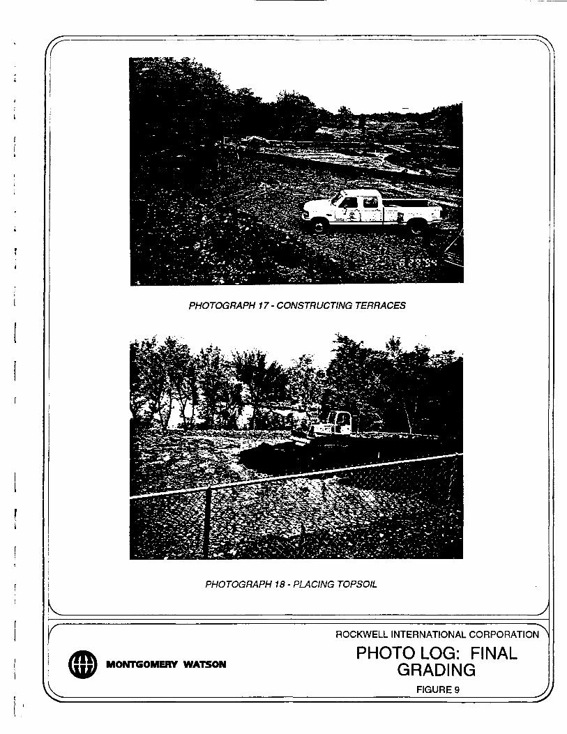
PHOTOGRAPH 17-CONSTRUCTING TERRACES
PHOTOGRAPH 18 - PLACING TOPSOIL
J
MONTGOMERY WATSON
ROCKWELL INTERNATIONAL CORPORATION^
PHOTO LOG: FINALGRADING
___________FIGURE 9__________ n

PHOTOGRAPH 19 • DRAINAGE CHANNELS
PHOTOGRAPH 20 - DRAINAGE CHANNELS
MONTGOMERY WATSON
ROCKWELL INTERNATIONAL CORPORATION^
PHOTO LOG: AS-BUILTCONSTRUCTION
FIGURE 10

PHOTOGRAPH 21 • DRAINAGE TERRACES
PHOTOGRAPH 22 - DRAINAGE TERRACES
MONTGOMERY WATSON
ROCKWELL INTERNATIONAL CORPORATION
PHOTO LOG: AS-BUILTCONSTRUCTION
__________FIGURE 11__________ Jt

PHOTOGRAPH 23 • MONITORING WELL EXTENSIONS
PHOTOGRAPH 24 - CREEK CROSSING
MONTGOMERY WATSON
ROCKWELL INTERNATIONAL CORPORATION
PHOTO LOG: AS-BUILTCONSTRUCTION
__________FIGURE 12__________ //

PHOTOGRAPH 25 - TEMPORARY ACCESS ROAD
PHOTOGRAPH 26 - TEMPORARY ACCESS ROAD
MONTGOMERY WATSON
ROCKWELL INTERNATIONAL CORPORATION
PHOTO LOG: AS-BUILTCONSTRUCTION
___________FIGURE 13__________ Jl