Remote Welding Final Report 5-21-12a - … Korea Project Remote Capsule Closure Welding System Final...
84
The INL is a U.S. Department of Energy National Laboratory operated by Battelle Energy Alliance INL/LTD-12-26065 Korea Project Remote Welding System Final Report Larry Zirker Ben Cowan May 2012
-
Upload
truonglien -
Category
Documents
-
view
217 -
download
3
Transcript of Remote Welding Final Report 5-21-12a - … Korea Project Remote Capsule Closure Welding System Final...

The INL is a U.S. Department of Energy National Laboratory operated by Battelle Energy Alliance
INL/LTD-12-26065
Korea Project Remote Welding System Final Report
Larry Zirker Ben Cowan
May 2012

DISCLAIMER
This information was prepared as an account of work sponsored by an agency of the U.S. Government. Neither the U.S. Government nor any agency thereof, nor any of their employees, makes any warranty, expressed or implied, or assumes any legal liability or responsibility for the accuracy, completeness, or usefulness, of any information, apparatus, product, or process disclosed, or represents that its use would not infringe privately owned rights. References herein to any specific commercial product, process, or service by trade name, trade mark, manufacturer, or otherwise, does not necessarily constitute or imply its endorsement, recommendation, or favoring by the U.S. Government or any agency thereof. The views and opinions of authors expressed herein do not necessarily state or reflect those of the U.S. Government or any agency thereof.

INL/LTD-12-26065
Korea Project Remote Welding System Final Report
Larry Zirker Ben Cower
May 2012
Idaho National Laboratory Idaho Falls, Idaho 83415
http://www.inl.gov
Prepared for the U.S. Department of Energy
Under DOE Idaho Operations Office Contract DE-AC07-05ID14517

iii
CONTENTS
1. BACKGROUND ................................................................................................................................ 1
1.1 Milestones and Objectives ....................................................................................................... 1
2. PROJECT RESULTS ......................................................................................................................... 2
2.1 Conduct Mission Analysis ....................................................................................................... 2
2.2 Develop Project Requirements and Deliverables ..................................................................... 2
2.3 Obtain Welding Power Supply................................................................................................. 3
2.4 Construct the Mock-up Remote Welding System .................................................................... 3
2.5 Fabricate Components for Welding Coupons .......................................................................... 4
2.6 Develop Welding Parameters ................................................................................................... 4
2.7 Conduct Plenum / Closure Weld Tests .................................................................................... 5
2.8 Conduct Helium Weld Tests .................................................................................................... 5
2.9 Set-up Data Acquisition System .............................................................................................. 6
2.10 Develop Data Acquisition Signature ........................................................................................ 7
2.11 Conduct Laser Welding ........................................................................................................... 7
2.12 Conduct Resistance Welding ................................................................................................... 7
2.13 Verify Rodlets and Capsules Comply with ATR Procedures .................................................. 8
2.14 Develop Draft Design of Remote In-Cell Welding System ..................................................... 8
2.15 Issue Final System Report ........................................................................................................ 8
3. CONCLUSIONS ................................................................................................................................ 8
Appendix A Mission Analysis and Laboratory Instruction Documents .................................................... 11
Appendix B Technical / Functional Requirements Matrix ........................................................................ 37
Appendix C Trade Study ........................................................................................................................... 39
Appendix D Photographs of the Mock-up Welding System ...................................................................... 41
Appendix E Components for Welding Coupons ........................................................................................ 43
Appendix F Welding Parameters ............................................................................................................... 47
Appendix G Plenum / Closure Weld Tests ................................................................................................ 59
Appendix H Helium Preliminary Study ..................................................................................................... 67
Appendix I Set-up Data Acquisition System Arc Agent 3000P onto a Miller MaxStar 300 ..................... 69
Appendix J Data Acquisition Signature ..................................................................................................... 71
Appendix K Resistance Welding ............................................................................................................... 73
Appendix L Draft Design of Remote In-cell Welding System .................................................................. 75

iv
FIGURES Figure 1. Draft rodlet and over jacket materials and configurations ........................................................... 14
Figure 2. new end plug with relieve grove .................................................................................................. 14
Figure 3. new end plug insert into cladding ................................................................................................ 14
Figure 4. earlier EBR-II end plug designs .................................................................................................. 15
Figure 5. 1992 in-cell closure welding system design ................................................................................ 15
TABLES Table 1. Trade-off study of in-cell fuel closure welding process ............................................................... 16
Table 2. Table of risks and controls. ........................................................................................................... 21
Table 3. Hazard scenarios that require mitigation. ..................................................................................... 31
Table 4. Waste types and disposal methods. ............................................................................................... 31
Table 5. Training required .......................................................................................................................... 32
Table 6. Records and retention periods. ...................................................................................................... 35
1
Korea Project Remote Capsule Closure Welding System Final Report
1. BACKGROUND The overall thrust of the United States (US)-Republic of Korea (ROK) International Nuclear Energy
Research Initiative (INERI) and Joint Fuel Cycle Studies Project is to reprocess used light water reactor (LWR) fuel elements, cast the reprocessed fuel into fuel slugs, encapsulate the fuel slugs into rodlets, irradiate the fuel in the Advanced Test Reactor (ATR), and then conduct post irradiation examination (PIE) of the irradiated fuel slugs. The quality and precision of welded fuel elements is paramount to meeting project objectives and to the nuclear environment, in general.
One of the main deliverables for this project is defining a repeatable welding process coupled with remote hardware capable of generating consistent and reliable closure welds. Other considerations include:
Minimal design risk and developmental time. All equipment and systems should be commercial off-the-shelf (COTS) to the extent possible, and should leverage other designs and existing systems
System designed for hot cell operations. All designs should be based on operability in a hot cell environment using master slave arms and manipulators.
Capability to producing twelve pins per day. The capsule welding system should be capable of welding twelve closure welds a day. The system needs to be robust, and not centered around a high throughput of pins.
This report captures the due diligence conducted to ascertain the best hardware or systems for supporting the remote capsule closure welding process.
1.1 Milestones and Objectives Two project milestones drove the remote capsule closure welding portion of the project:
Conduct experimental testing and develop capsule closure welding procedure or programmable welding sequence by 12/2012
Create a draft remote capsule closure welding station design by 12/2012.
The general objectives intended to meet the above milestones were as follows:
1. Generate the technical and functional requirements for a mock-up welding station
2. Develop an initial mock-welding system to conduct welding research and development (R&D)
3. Conduct welding process analysis
4. Develop the data acquisition process
5. Design a draft remote capsule welding system
6. Write a final report.

2
2. PROJECT RESULTS The project tasks capture the essence of the project and outline the contents of the final report.
Supplemental data supporting the tasks is contained in the appendices.
Conduct mission analysis
Develop project requirements and deliverables
Obtain welding power supply
Construct the mock-up remote welding system
Fabricate components for welding coupons
Develop welding parameters
Conduct plenum / closure weld tests
Conduct helium weld tests
Set-up data acquisition system
Develop data acquisition signature data
Conduct laser welding
Conduct resistance welding
Verify rodlets and capsules comply with ATR procedures
Develop draft design of remote in-cell welding system
Issue final system report.
2.1 Conduct Mission Analysis
Task Compliance Measure Status % Complete Notes
Conduct Mission Analysis
Mission analysis document written
Completed 100 Found in appendix A
The mission analysis for developing a remote capsule closure welding system was conducted at the beginning of the project to identify aspects of project and gather a thumbnail sketch of the scope, goals, tasks, and deliverables of the project. A mission analysis document was written and used as a baseline for the subsequent work. Aspects of the mission analysis evolved over the project, and the project task list has changed to reflect that evolution. Appendix A contains the original mission analysis document, as well as a draft Laboratory Instruction (LI) that gives authorization or permission to perform weld development research in the laboratory. The LI was based on many of the tasks listed above.
2.2 Develop Project Requirements and Deliverables
Task Compliance Measure Status % Complete Notes
Develop project requirements and deliverables
The technical / functional requirements matrix is written
Completed 100 The technical / functional requirements matrix is found in Appendix B
The Technical / Functional Requirements Matrix contained in Appendix B shows the basis for the project requirements and provides a link to the project timeline, as found in the Mission Analysis document. This matrix was the first cut at defining what tasks had to be accomplished by the project.

3
The evolution of project tasks is tracked using the project GANTT chart kept by the project controls manager.
2.3 Obtain Welding Power Supply
Task Compliance Measure Status % Complete Notes
Obtain welding power supply
The programmable welding power supply is set-up in the welding laboratory
Completed 100 A preliminary trade-off study selected a GTAW process. This trade-off study is in Appendix C
Several programmable gas tungsten arc welding (GTAW) power supplies were investigated at the November 2011 FabTech /American Welding Society Convention and Trade Show. Section 5 of the Trade-off Study of Systems Supporting the Capsule Closure Welding Process was devoted to selecting the Miller Electric MaxStar GTAW power supply. The Miller Electric MaxStar system was selected as the optimum power supply for several reasons. In addition to a $10,000 lower cost over its competitors, the MaxStar system has an excellent built-in programmable computer and another Idaho National Laboratory (INL) Materials and Fuels Complex (MFC) program already had one of these systems on site. That system was made available to the welding team for the duration of this test.
2.4 Construct the Mock-up Remote Welding System
Task Compliance Measure Status % Complete Notes
Construct the mock-up remote welding system
Mock-up remote welding system set up in the welding laboratory
Completed 100 The mock-up remote welding system is the baseline for the subsequent in-cell welding system. This system was used to develop the programmable welding protocols for in-cell welding and the draft in-cell welding system design. See Appendix D for photographs of the welding system.
The GTAW welding of end plugs for encapsulating rodlets is a mature process but requires precision alignment. Planning, designing, and procuring parts for the construction of a mock-up remote welding system lead to just such precision welding system. The aspects of the welding system include an adjustable stand, torch holder, XYZ direction micro-positioners, solid base, two collets, collet holder, and grounding cable connections. Two collets (0.230 and 0.274) with a common holder were used to secure the rodlets while the XYZ positioners placed the tip of the end plug exactly under the sharpened tungsten electrode. Appendix D shows photographs of all aspects of the mock-up remote welding system.
4
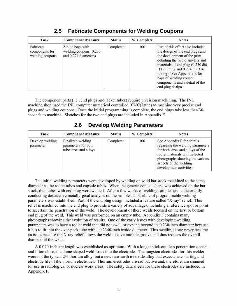
2.5 Fabricate Components for Welding Coupons
Task Compliance Measure Status % Complete Notes
Fabricate components for welding coupons
Ziploc bags with welding coupons (0.230 and 0.274 diameters)
Completed 100 Part of this effort also included the design of the end plugs and the development of the print detailing the two diameters and materials of end plug (0.230 dia HT9 tubing and 0.274 dia 316 tubing). See Appendix E for bags of welding coupon components and a detail of the end plug design.
The component parts (i.e., end plugs and jacket tubes) require precision machining. The INL machine shop used the INL computer numerical controlled (CNC) lathes to machine very precise end plugs and welding coupons. Once the initial programming is complete, the end plugs take less than 30-seconds to machine. Sketches for the two end plugs are included in Appendix E.
2.6 Develop Welding Parameters
Task Compliance Measure Status % Complete Notes
Develop welding parameter
Finalized welding parameters for both tube sizes and alloys
Completed 100 See Appendix F for details regarding the welding parameters for both sizes and alloys of the rodlet materials with selected photographs showing the various aspects of the welding development activities.
The initial welding parameters were developed by welding on solid bar stock machined to the same diameter as the rodlet tubes and capsule tubes. When the generic conical shape was achieved on the bar stock, then tubes with end plug were welded. After a few weeks of welding samples and concurrently conducting destructive metallurgical analysis on the samples, a baseline of programmable welding parameters was established. Part of the end plug design included a feature called “X-ray” relief. This relief is machined into the end plug to provide a variety of advantages, including a reference spot or point to ascertain the penetration of the weld. The development of these welds focused on the first or bottom end plug of the weld. This weld was performed on an empty tube. Appendix F contains many photographs showing the evolution of results. One of the early issues with developing welding parameters was to have a rodlet weld that did not swell or expand beyond its 0.230-inch diameter because it has to fit into the over-pack tube with a 0.2340-inch inside diameter. This swelling issue never became an issue because the X-ray relief allows the weld to cave into the groove and thus reduces the overall diameter at the weld.
A 0.040-inch arc length was established as optimum. With a longer stick out, less penetration occurs, and if too close, the dome shaped weld fuses into the electrode. The tungsten electrodes for this welder were not the typical 2% thorium alloy, but a new rare-earth tri-oxide alloy that exceeds arc starting and electrode life of the thorium electrodes. Thorium electrodes are radioactive and, therefore, are shunned for use in radiological or nuclear work areas. The safety data sheets for these electrodes are included in Appendix F.

5
2.7 Conduct Plenum / Closure Weld Tests
Task Compliance Measure Status % Complete Notes
Conduct plenum / closure weld tests
Upgraded computerized welding parameters with reduced plenum volume for both tube sizes and alloys
Completed 100 The welding values for the plenum welds have been adapted as the closure welding parameters. See Appendix G
The initial welding parameters were developed by welding on end plugs inserted into short sections of jacket tubing. This is an open-ended coupon, meaning there is no back pressure. However, this configuration is not the in-cell welding configuration. The in-cell welding is the closure weld on a rodlet that is filled with fuel and sodium or an over pack capsule with a rodlet in side.
Historically, these closure welds periodically demonstrate a “blow out” condition that is attributed to the build-up of air pressure during welding. The plenum / closure weld tests were performed on a tube that had a welded end plug on the bottom of the tube and was filled with a surrogate material (solid slug) to simulate an actual final weld with a shortened plenum. Typically, the plenum welding coupon has a three-inch plenum volume between the end of the surrogate material and the top end plug. One or two initial plenum test welds displayed blow out welds. To solve this, it was decided to reduce the air volume available for heating or pressurizing. To reduce the air volume, three things were done: (1) the end plug design was altered (removed the flats) to not allow air to move from the tube into the weld joint; (2) the X-ray relief volume was cut in half (reduced to 0.03 X 0.06-inch);, and (3) the welding parameters were programmed to accelerate the welding time (0.6 seconds) to reduce the air pressure build up time. These adjusted welding parameters are the final closure welding parameters.
Another method (i.e., chill block) was deployed to reduce the heating of the air. Surprisingly, tests using a copper chill block also showed blow out welds. Examples of this are shown in Appendix G. Upon metallurgical analysis, it was discovered that the chill block took energy from end plug, causing it not to melt into the end of the tube. Photographs in Appendix G show this condition. To solve this problem, additional amperes were programmed into the welds to compensate for the chilling. Subsequently, the copper chill block was abandoned because of the complexity of this operation in the hot cell. To supplement the cooling of the end plug and tube, the steel collet was replaced with a brass collet. Brass does not cool as fast as copper, but the cooling affect greatly exceeds that of steel. Welding parameters were increased to compensate for this heat loss of the collet. Because the lack of heat appears to cause a blow out hole, the disposition is to immediately re-weld the end plug. This has been done with good results and should become the path forward to fix blow out holes.
2.8 Conduct Helium Weld Tests
Task Compliance Measure Status % Complete Notes
Conduct helium weld tests
Test showing that helium gas back filling has no affect on welding
In Process 35 See Appendix H for details regarding filling the capsule with helium. More testing needs to be done to obtain a definitive answer to the question.
Helium assists the heat transfer between the fuel bearing 0.230 diameter tube and the larger 316 tube. GTAW welding is typically conducted in an argon gas environment, but there is a synergism between helium gas and the electric arc that has a direct affect on increasing the weld penetration and weld size.

6
Helium has high thermal conductivity and high ionization potential, which produces higher arc voltages when compared to using argon shielding gas for a given current setting and arc length. This produces a "hotter" arc. The increased heat input affects depth of penetration, and its wider arc column increases weld bead width.
Helium weld tests were conducted to assess the effect of the helium back-fill within the annulus and plenum of the large 0.274-diameter 316 capsule. Specifically, the tests proposed to (1) assess the press fit seal between the tube and end plug to retard the escape of the helium and (2) ascertain any affect from the helium in the annulus on welding the closure weld. The proposed test steps included:
Fill a capsule with helium gas for one minute
Press an end plug into the capsule to seal or trap the helium in the capsule (repeat process for two test samples)
Take the two samples to the helium leak tester to determine the leak rate
Conduct leak rate testing
Return the samples to the welding laboratory and seal weld the top end plug
Conduct metallurgical analysis to assess any change in depth or penetration of weld.
Further tests need to be done to evaluate the tightness of the press fit of the end plug and to ascertain the leak rate of the seal. This data is needed to develop the procedure for the future in-cell welding of the capsules.
The bulleted list below includes the test inspectors actual report notes from the helium weld tests:
Had (4) SS-316 bottom capsule welds leak tested ( <1.0 x 10⁻⁸ cc/s) (good)
Had (2) SS-316 capsules loaded with helium with swedged end plugs leak tested. Both PT-14 and PT-15 were leak checked together in bell jar... >1.0 x 10⁻⁵ cc/sec... had them checked again individually and the following results were ... Capsule PT-15 had no helium left (leaked out)... and Capsule PT-14 leak rate was 2 x 10⁻⁵ cc/sec (not good).
These tests need to be re-done because these test results were neither definitive nor conclusive.
2.9 Set-up Data Acquisition System
Task Compliance Measure Status % Complete Notes
Set-up data acquisition system
Welding parameter signatures shall be captured and viewed on a monitor
Completed 100 See Appendix I for photographs of the system and hardware connections
The set up of the data acquisition system was a straight forward installation of software and connecting some pieces of hardware. After a few telephone calls, the system was set up and recording data.

7
2.10 Develop Data Acquisition Signature
Task Compliance Measure Status % Complete Notes
Develop data acquisition signature data
Twelve welding parameter signatures can be captured for capsule and rodlet closure welds
In Process 25 See Appendix J for print-outs of the signatures
Developing an electronic signature of the volts and amperes of a welding process has multiple uses. The Arc Agent 3000, an Impact Welding system, is a real-time arc weld monitoring system with a high data acquisition rate that reads data in the millisecond range. Once an established welding parameter signature has been captured, the software has features to program limits to bound the upper and lower ranges of the welding parameters or procedure. This bounding limit alarms when a production weld exceeds the bounded limits. Secondarily, this signature provides effective evidence of weld quality. Weld quality can be validated by metallurgical analysis. If the welding stays within the established bounds, then inherently the weld meets the intended quality. This aspect of data acquisition is essential for establishing quality since traditional hands-on, non-destructive examination methods are not possible with in a nuclear hot cell environment. This task is not complete, but it is ready to capture the signature for both the capsule and rodlet top end plug closure welds. This task will also document the closure weld parameters for subsequent use.
2.11 Conduct Laser Welding
Task Compliance Measure Status % Complete Notes
Conduct laser welding
Macro photographs of the resultant welds show 125% effective throat of the welds.
In Process 80 See Appendix J for photographs of laser welding
The results of the first two laser welding sessions showed that the process was viable, but the results of the last weld showed both porosity and cracking. A third test or suite of tests needs to be conducted to validate the process. This task will be conducted in the future, when needed.
2.12 Conduct Resistance Welding
Task Compliance Measure Status % Complete Notes
Conduct resistance welding
Macro photographs of the resultant welds show 125% effective throat of the welds.
In Process 5 See Appendix K for photographs of the welding system
The INL resistance welding system has been set up in a new welding shop location, but two welding collets for the electrode tooling fixtures need to be fabricated before welding can be conducted. The test needs a couple weeks to get the collets, perform the welds, and complete the metallurgical analysis. This can be conducted at a future date with the alloys of choice. The project welding engineer retired before this test could be completed.

8
2.13 Verify Rodlets and Capsules Comply with ATR Procedures
Task Compliance Measure Status % Complete Notes
Verify rodlets and capsules comply with ATR procedures
An email from the ATR experimenter that the rodlet and capsule hardware meet ATR procedures
In Process 10 No experimenter has been assigned to date to approve the hardware of the experiment.
The goal of this task is to present the hardware (i.e., the capsule and rodlet end plug) design for approval. An unofficial visit with an ATR experimenter confirmed that at this point in the evolution of a final design, nothing appeared to be out of the ordinary or to be a show-stopper. This task will be started when the project is assigned an ATR experimenter for final disposition.
2.14 Develop Draft Design of Remote In-Cell Welding System
Task Compliance Measure Status % Complete Notes
Develop draft design of remote in cell welding system
Draft drawing showing the remote welding system
Completed 100 See Appendix L for the final draft
Lessons learned from using the prototype system were rolled together to develop the draft design. The essence of the design is two collet holders that pivot. This allows the operator to place the rodlet or capsule into its designated collet and then rotate it under the tungsten electrode for welding. When finished, the operator then pivots out the rodlet or capsule, removes the welded element, and replaces it with another element to be welded. This is a very precise but robust system to weld the dozen or so elements for this test.
2.15 Issue Final System Report
Task Compliance Measure Status % Complete Notes
Issue final system report
Final report approved for external release
Complete 100
This document constitutes the final report.
3. CONCLUSIONS The two major goals of the project were accomplished by this effort.
Conduct experimental testing and develop capsule closure welding procedure or programmable welding sequence by 12/2012
Create a draft remote capsule closure welding station design by 12/2012.
Highlights of this effort are as follows:
Developed the welding parameters for GTAW burst welding for closure welding of capsules and rodlets

9
Constructed a robust, precision capsule and rodlet welding system for use on future R&D welding efforts
Installed the data acquisition system to monitor both quality of welds and to directly assist in future R&D welding efforts
Discovered techniques to reduce the affect of blow-outs on tube closure welds. Directly linked to air pressure (too long of welding time) but also to the lack of input energy into the end plug to coalesce both the end plug and tube
Discovered that the welding of capsules and rodlet end plugs can greatly vary if the grounding and welding cables are coiled-up verse laid out on the ground
Verified that the rare earth oxide tungsten electrodes function perfectly with no miss-fires or sputtering common to earlier work, and do not contribute to spreading radioactive material when sharpening the electrodes
Defined the feed through needs of the Advanced Welding System:
Two welding cables, Number 0 size
One gas hose for argon gas
Two signal wires for the remote vision system
One signal wire for the Automatic Voltage Control system.
This comprehensive final report shows that most of the initial project tasks were achieved. The major fault or reason why these tasks were not finalized resulted from the untimely MFC stand-down in April 2012 and the retirement of the principal welding engineer in May 2012. Details on the unfinished tasks include:
Verify rodlets and capsules comply with ATR procedures and ensure that the rodlet and capsule hardware is allowed in the ATR reactor. This will be finalized when the project is assigned an ATR experimenter.
Conduct resistance welding. This will be completed if required by the project manager. The secondary welding engineer to support this task could include Denis Clark.
Conduct laser welding. This will be completed if required by the project manager. Need to achieve more (~20%) penetration by the laser beam. The secondary welding engineer to support this task could include Marvin Harker and may include the IRC technician D.C. Haggard.
Conduct helium weld tests. The helium weld tests require a few tests to determine any harmful effects of the helium in the capsule and to determine the leak rate of the seal between the capsule end plug and tube. Because of the April 2012 Stand Down at MFC, this effort was stopped.
Develop data acquisition signature data. The data acquisition signature effort was stopped because to the April 2012 Stand Down at MFC. A suite of end plugs and tubes are ready for testing. The signatures for both tube sizes (and alloys) could be completed in a couple of days. This effort would coincide with the finalization of the closure welding parameters. The closure welding parameters could also be deployed for the bottom end plug welds.

10
This page intentionally left blank.

11
Appendix A
Mission Analysis and Laboratory Instruction Documents

12
Appendix A Mission Analysis and
Laboratory Instruction Documents
Korea Project Fuel Cladding and Remote Element Fabrication System
Problem Statement: No INL welding system exists for remote closure welding of fuel elements in hot cell
Mission Statement: By the end of the calendar year (CY) 2012, develop an engineering scale prototype welding system for demonstration and weld qualification in the mock up lab at FCF.
Statement of Work: Define the technical and functional requirements for the project. Select the optimum welding process for the closure welds, and procure an adequate programmable welding system. Verify that welding processes under consideration for rodlet and capsule system is acceptable to the ATR as a AFC-3 drop in design. Develop a engineering scale mock up of the system. Ensure that materials for the project meet the configuration and quality requirements for MFC nuclear operations. Obtain welding coupons and end plugs for the welding qualification. Ensure the welding procedures are programmatically qualified and that the system has to robustness to perform in the hot cell and can perform a 1000 welds.
Goals or Objectives:
1. Select a welding process to perform the cladding and remote fuel element closure welding in cell through a detailed trade study
2. Capture the technical and functional requirements for the mock up
3. Develop an engineering scale mock up welding system to perform the remote closure welding of fuel elements in HFEF
4. Obtain the materials for the fuel cladding and rodlets
5. Ensure the design for rodlets and outer tube fit into a previous ATR design
6. Qualify the welding procedure for the cladding and rodlets
Task List Linked to Objectives by Number:
1.1 Conduct a trade-off study to identify the most feasible fuel element closure welding process
1.2 Selection the optimum welding systems
1.3 Purchase a welding power supply
2.1 Conduct a mission analysis for the project
2.2 Define the project requirements, stakeholders, tasks and deliverables
3.1 Define the parts of the remote welding system
3.2 Design the welding system
3.3 Procure parts and system components
3.4 Build the welding system
13
3.5 Assemble the prototype system in the Mock up Lab
3.6 Conduct V&V tests in the Mock up Lab
4.1 Order materials for jackets, rodlets, and end plugs
4.2 Fabricate test coupons
5.1 Ensure the jacket, rodlets, and end plugs are allowed into ATR
6.1 Qualify the closure weld welding procedure—rodlet and the over jacket closure weld
6.2 Verify the bottom end plug welding procedure
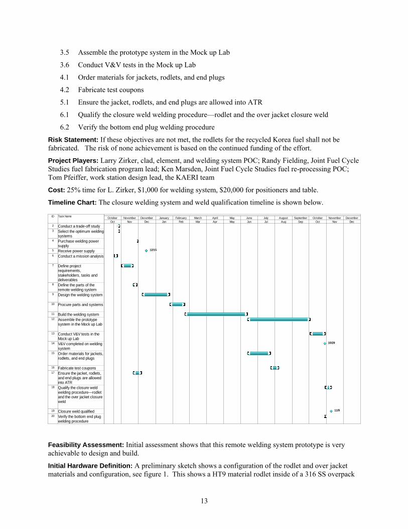
Risk Statement: If these objectives are not met, the rodlets for the recycled Korea fuel shall not be fabricated. The risk of none achievement is based on the continued funding of the effort.
Project Players: Larry Zirker, clad, element, and welding system POC; Randy Fielding, Joint Fuel Cycle Studies fuel fabrication program lead; Ken Marsden, Joint Fuel Cycle Studies fuel re-processing POC; Tom Pfeiffer, work station design lead, the KAERI team
Cost: 25% time for L. Zirker, $1,000 for welding system, $20,000 for positioners and table.
Timeline Chart: The closure welding system and weld qualification timeline is shown below.
ID Task Name
2 Conduct a trade-off study3 Select the optimum welding
systems4 Purchase welding power
supply5 Receive power supply6 Conduct a mission analysis
7 Define project requirements, stakeholders, tasks and deliverables
8 Define the parts of the remote welding system
9 Design the welding system
10 Procure parts and systems
11 Build the welding system12 Assemble the prototype
system in the Mock up Lab
13 Conduct V&V tests in the Mock up Lab
14 V&V completed on welding system
15 Order materials for jackets,rodlets, and end plugs
16 Fabricate test coupons17 Ensure the jacket, rodlets,
and end plugs are allowed into ATR
18 Qualify the closure weld welding procedure—rodlet and the over jacket closure weld
19 Closure weld qualified20 Verify the bottom end plug
welding procedure
12/15
10/29
11/9
Oct Nov Dec Jan Feb Mar Apr May Jun Jul Aug Sep Oct Nov DecOctober November December January February March April May June July August September October November December
Feasibility Assessment: Initial assessment shows that this remote welding system prototype is very achievable to design and build.
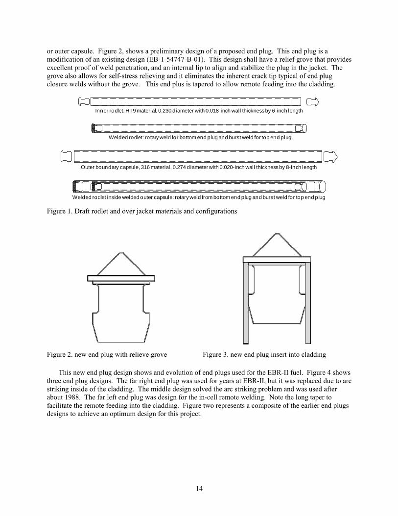
Initial Hardware Definition: A preliminary sketch shows a configuration of the rodlet and over jacket materials and configuration, see figure 1. This shows a HT9 material rodlet inside of a 316 SS overpack
14
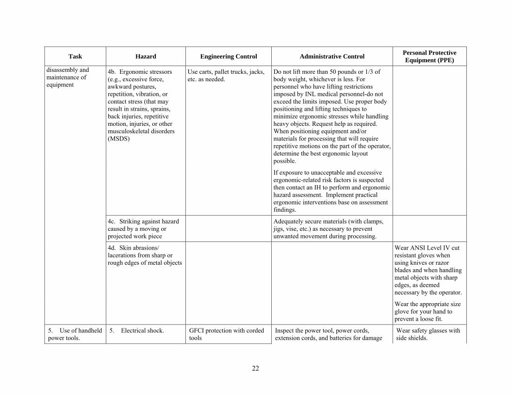
or outer capsule. Figure 2, shows a preliminary design of a proposed end plug. This end plug is a modification of an existing design (EB-1-54747-B-01). This design shall have a relief grove that provides excellent proof of weld penetration, and an internal lip to align and stabilize the plug in the jacket. The grove also allows for self-stress relieving and it eliminates the inherent crack tip typical of end plug closure welds without the grove. This end plus is tapered to allow remote feeding into the cladding.
Inner rodlet, HT9 material, 0.230 diameter with 0.018-inch wall thickness by 6-inch length
Welded rodlet: rotary weld for bottom end plug and burst weld for top end plug
Outer boundary capsule, 316 material, 0.274 diameter with 0.020-inch wall thickness by 8-inch length
Welded rodlet inside welded outer capsule: rotary weld from bottom end plug and burst weld for top end plug
Figure 1. Draft rodlet and over jacket materials and configurations
Figure 2. new end plug with relieve grove Figure 3. new end plug insert into cladding
This new end plug design shows and evolution of end plugs used for the EBR-II fuel. Figure 4 shows three end plug designs. The far right end plug was used for years at EBR-II, but it was replaced due to arc striking inside of the cladding. The middle design solved the arc striking problem and was used after about 1988. The far left end plug was design for the in-cell remote welding. Note the long taper to facilitate the remote feeding into the cladding. Figure two represents a composite of the earlier end plugs designs to achieve an optimum design for this project.

15
Figure 4, earlier EBR-II end plug designs
Talking with MFC engineers, it was discovered that a preliminary design for an in-cell closure welding system was designed in 1992, see Figure 5. Upon analysis this designs appears to quite adequate for an engineering scale mock-up design.
Figure 5, 1992 in-cell closure welding system design
The trade-off study to determine the optimum fuel element welding process is shown in Figure 6.

16
Table 1. Trade-off study of in-cell fuel closure welding process
Criteria: Cost of Welding System is defined as the cost purchase a total functioning welding system to perform the closure welds.
Deployable in Hot Cell is defined as the time needed to replace the equipment, item or personnel.
Foot Print of Welding System is defined as an estimate on in increase of productivity if the HFEF hot cell piece of equipment, item or personnel were replaced or added.
Weight is the multiplier value that is arbitrarily defined by the project team to represent a weight factor of importance to the criteria. The weight values are between 1 to 7 with 7 being the best.
Value Ranking is a decompositional breakdown that provides a range of values or basis for ranking the Limitation with the Criteria.
Score is the product of the Weight and the Value of each Criterion.
Total is the sum of all scores for each Limitation. The highest score wins as most important.
No. Criteria
Weight (1 to 7 with 7
as best)
Value Ranking
Value (1 to 12
with 12 as best)
1 2 3
Gas Tungsten Arc Welding
Laser Welding Resistance Butt Welding
Wt X Value = Score Wt X Value = Score Wt X Value = Score
1 Cost of
Welding System
3
<$5,000 12
<
$5,0
00
36 >
$30,
000
3 >
$30,
000
3 $5,000 to $10,000
8
$20,000 to $30,000
4
>$30,000 1
2 Deployable in
Hot Cell 7
Easy 12
E
asy
84
Dif
ficu
lt 28
Lot
s of
E
ffor
t 7 Doable 8
Difficult 4 Lots of Effort 1
3
In-Cell Foot Print of Welding System
6
<2 ft2 12
<
2 ft
2 72
2 to
4 f
t2
48 >
6ft2
6 2 to 4 ft2 8
4 to 6 ft2 4
>6ft2 1
Totals --- 130 --- 79 --- 16

17
Laboratory Instruction for Weld Development Research
PROJECT The remote welding system mock-up project intends to develop a mock-up of a remote welding system (first draft) for the Joint Fuel Cycle Study with Korea. Eventually a remote fuel element welding system shall be built for HFEF deployment, and this HFEF effort shall evolve from this mock-up work. This initial effort shall
Develop the closure welding procedures for two sizes of tubes/jackets
Qualify a welding technician
Design the end plugs for welding and inspectability
Procure and assemble the components of the mock-up of the welding system:
positioning slides with torch and element holding collets
remote cameras for positioning
data acquisition capabilities
digital record of the welded end plug to tube welds
SCOPE The scope of this project develops the basis for the future HFEF remote welding system. The initial scope builds a mock-up system and develops the welding procedures. Secondarily the scope includes developing the ancillary systems to support the welding system: vision system, positioning system and data acquisition system. The primary effort assembles the mock-up welding system, develops the welding procedures; integrates a camera and data acquisition systems with the welding and develops a database of welded end plug photographs. The welding essentially seals an end plug to a jacket with a single pulse weld or spot weld. The bottom end plug welding uses an existing orbital tube welding system. Additional details for the R&D welding in MFC-789 are included in Appendix A.
PERSONNEL The project PI is Randall Fielding. The welding engineer is Larry Zirker and the main technician support is Ben Cowan.
RESEARCH ACTIVITY DESCRIPTION
1 Program Objectives:
The objective of this effort is 1. To develop a functional welding system mock-up of a future remote system, and 2. Conduct this assemble and prototype work in MFC-789 laboratory. The primary objective of this laboratory is to obtain fundamental data to support the technology development associated with meeting the goals of the Korea Fuel Cycle effort. The Engineering Development Laboratory 789 is setup to facilitate applied Research and Development (R&D) activities. These R&D activities are intended to explore and discover original and enhanced methods, techniques, or materials. To allow the researcher flexibility but provide appropriate hazards identification and mitigations, this LI lists the reviewed R&D activities, the hazards, and the required mitigations. Any program/project may utilize this LI; however, program/project specific requirements, hazards, and

18
mitigation will be addressed in a program/project specific document (i.e., process work sheet, experimental plan, project-specific environmental checklist etc.) and approved by the Laboratory Manager to assure this LI appropriately bounds the scope, hazards, and mitigations of the work.
2 Project Approach:
The project approach shall
Develop the closure welding procedures for two sizes of tubes/jackets
Qualify a welding technician
Design the end plugs for welding and inspectability
Procure and assemble the components of the mock-up of the welding system:
positioning slides with torch and element holding collets
remote cameras for positioning
data acquisition capabilities
digital record of the welded end plug to tube welds
Research toward the stated objectives is performed in building 789 at MFC using non-radioactive materials. The Engineering Development Laboratory 789 contains chemicals, equipment, and tools used in the preparation and experimentation of research activities such as sample preparation and welding. Some specific hazards germane to welding include: arc flashes, argon gas use, hot materials and the 480 volt powered welding system. The arc flashes shall be mitigated by shielding the workers and the co-located workers from the welding arc. The argon gas shall be mitigated with the low levels of welding—just periodic spot welds. Also the building is not air tight thus allowing ample air filtration into the labs. The welded samples are very small in diameter 0.3125 and will little mass. The welds are about one second in duration and the tube has ample length to handle without getting close to the welded end. To energize the welding system, the operator is qualified and follows the established procedure and wearing the appropriate personal protection equipment. The operator shall use a tong / pliers or gloved hand to remove hot samples if needed. This LI also includes initiating generic mitigations/requirements for handling spills, ensuring facility conditions, working under abnormal conditions and using instructional steps for working with hazardous materials (e.g., flammable materials, corrosives, etc.).
3 Project/Activity Description:
The scope of this project develops the basis for the future HFEF remote welding system. The scope builds a mock-up system and to develop the welding procedures. Secondarily the scope develops the ancillary systems to support the welding system: vision system, positioning system and data acquisition system. The primary effort assembles the mock-up welding system, develops the welding procedures; integrates a camera and data acquisition systems with the welding and develops a database of welded end plug photographs. The welding seals an end plug to a jacket. The bottom end plug welding includes orbital tube welding and the top end plug includes single short term pulse from a gas tungsten arc welding torch.
This LI covers work conducted in Building 789 involving research and development activities associated with missions and programs at the INL. Typical laboratory activities that are covered in this LI include:
Working in a facility where inert gas is utilized
Inert gas is used in the 789 facility to provide an inert environment to experiments. The gas can be plumbed to the experiments or used as the atmosphere in the gloveboxes. The 789 facility is an old large building and is not leak tight. Large fans are used to circulate the air through the room. The flow of argon gas into the system is regulated and therefore, reduces

19
the chance of a large release. Additionally, the gas flows through a flow meter or regulator further reducing the chance of a large release.
Experimental set-up and operation
Experimental set-up will typically use general laboratory “off-the-shelf,” equipment and where applicable, with vendor supplied instructions. Sample preparation, use of and construction with traditional material (e.g. steel, aluminum, and etc), general material handling activities, and handling powders (not nano-sized) will be part of normal experimental operations.
Use of hand tools (powered and non powered)
“Hand Tools” refers to both unpowered (e.g. hammers, wrenches, brushes) and powered equipment (e.g. drills, screwdrivers, scribing tools and hand shears). Equipment is to be free from defects that would inhibit safe usage and is to be inspected prior to use. Electrical cords are to be inspected and are to be used with GFCI protection.
Use of chemicals (handling, storage and disposal) identified in form 420.07 (See supporting information in EDMS)
Chemicals used in this LI are primarily of a general laboratory nature. Chemical types include organic solvents (e.g. ethanol and acetone), adhesives (including epoxies), lubricants, cleaners, coating agents (e.g. aerosol yttria), various metals (e.g. zirconium and magnesium).
All chemicals used under this LI must be included in the “Chemical Use Survey Form” (420.07) found in the ‘supporting information’ section of EDMS. New materials may be added to this form following by appropriate SME review (i.e. IH, Fire, IS, WGS, Environmental, and etc.).
Measurements (e.g. mass, visual, dimensional, weld, pH)
Measurements are made based on programmatic requirements with the quality level (and resulting calibration and inspection requirements) is specified in program documents. Visual inspections cover unaided as well as both handheld and desktop style magnifiers (e.g. stereoscopes and microscopes).
Chemical spill response
Chemical spills of a “minor” nature may be cleaned by the performer. “Minor” is typically defined as a small quantity (a few milligrams) that can be safely captured by lab wipes. Larger spills are only to be handled by trained personnel and are not covered under this work control.
Minor equipment maintenance.
Equipment may be serviced, per manufacturer’s direction, provided the hazards have been properly mitigated (e.g. exclusive control of electrical plug). Items of moderate to high hazard will be handled under different work control and may involve specialized training.
Gas systems are used to supply a flow of the desired gas to a process (e.g. inert cover gas to a furnace).
System lines (both vacuum and gas) are built to provide conduit for gas flow and may be have quick disconnect (e.g. Kline Flange), compression (e.g. Swagelok) or welded construction. Any system that has the potential to achieve a positive pressure (relative to the room) falls under Pressure System Assembler (PSA) guidance.
Changing/ handling/attaching compressed gas cylinders
Gas cylinders are routinely used in the facility to provide gas supply to equipment (electron microscopes) and as process gas. Hazards are mitigated by the controls stated in table 2.01.

20
Electrical work
Minor electrical work may be conducted on low hazard (< 50 Volt) system under this LI. Operation of equipment breakers (240 Volts and less) may be operated with the appropriate training and PPE. Operation of equipment breaker 240-600 volts may be operated with the appropriate training, PPE, and LM approval.
Welding, cutting, flame soldering, grinding or plasma arc cutting or otherwise producing sparks or flames
Welding, cutting, flame soldering, grinding or plasma arc cutting or otherwise producing sparks or flames may be performed to support basic or applied research and development as specified in a hot work permit.
4 Major Equipment Used in Activity:
The activities covered under this LI tend to be more general in nature involving more bench top work, work in gloveboxes, and other work spaces. Work on equipment may be covered (e.g. cleaning) under this LI provided that the hazards pertaining to the equipment have been mitigated or are judged to be insignificant. Typical equipment covered under this LI is:
Laboratory lathe
Mill
Hand tools
Welding power supply
5 Activity Location by Area, Building Number and Lab Room Number:
MFC, Building 789 throughout the facility
6 Activity Quality Level and QL Database Number:
All Activities are quality Level 3 and are covered under the following QLD’s or by a project specific QLD.
Purchasing general shop supplies and PPE for fabrication, mock-up and assembly activities: ALL-000101
Procurement of general Laboratory use supplies: MFC-000034.
Minor operational activities: All-000263.
7 Activity Environmental Checklist Title and Number:
Fabrication Technique Development in MFC-789: INL-11-012 (OA 12)
8 Activity Lab Manager, Laboratory Space Coordinator, and Principal Investigator:
Lab Manager: See placard at laboratory entrance
Lab Space Coordinator: See placard at laboratory entrance
Principal Investigators: Ken Bateman, Ben Cowan, Randall Fielding, Steven Frank, Guy Fredrickson, Paula Hahn, Steve Herrmann, Ken Marsden, Matt Morrison, Tom O’Holleran, Brenda Serrano-Rodriguez.
RISK AND CONTROLS
Risks and controls for this project are listed in Table 2. Hazards requiring mitigation are listed in Table 3. Waste types and disposal methods are listed in Table 4. Required training is listed in Table 5.

21
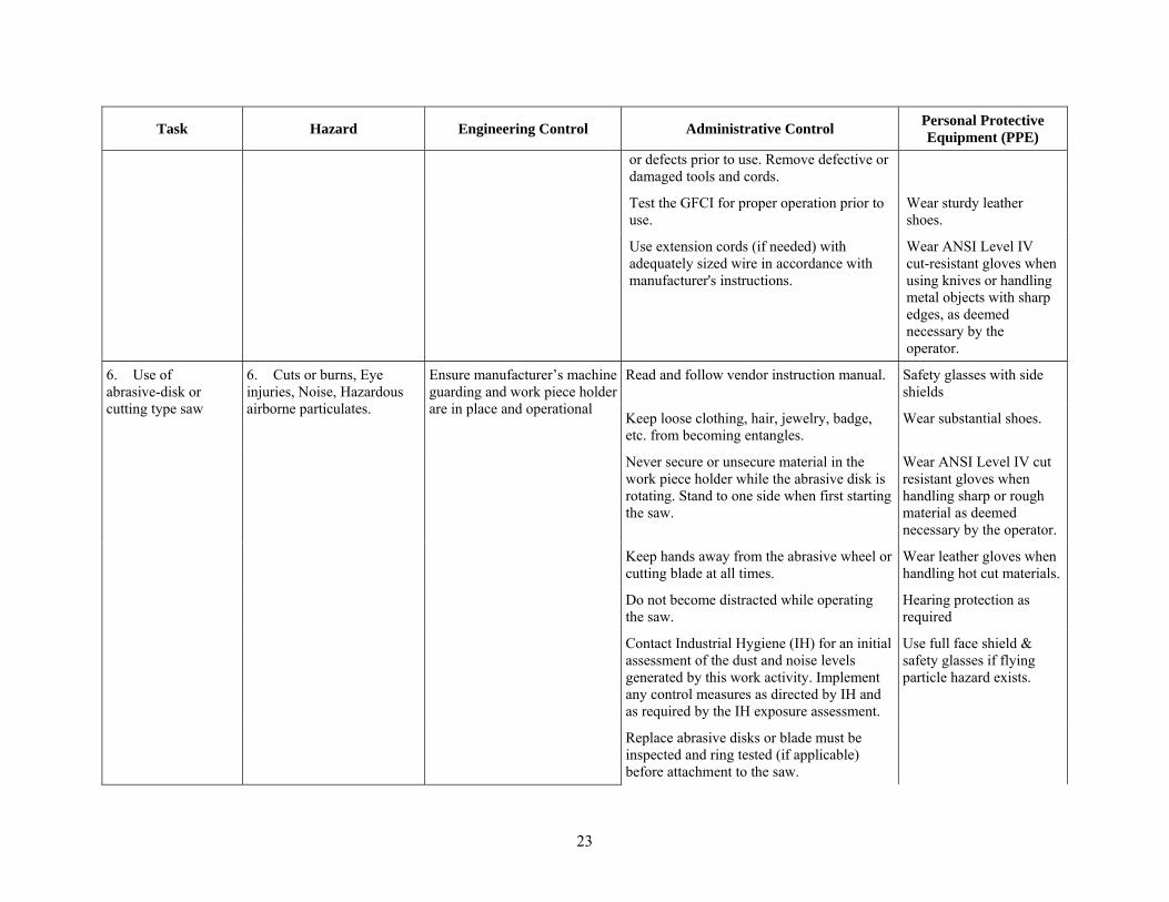
Table 2. Table of risks and controls.
Task Hazard Engineering Control Administrative Control Personal Protective Equipment (PPE)
1. Working alone 1. If a worker requires medical assistance, no one will be available to assist.
Provide means of communication (telephone, cell phone, 2 way radio, etc.) in the event help is needed.
Notify LM or LSC that you are working in the lab.
During normal working hours others normally frequent the area and activities can be performed alone.
Two people required for off shift work activities, if required by the LM
Keep the position of hands and arms within the neutral zone, relaxed with a 90 degree bend in elbow. Use work platforms to obtain the proper height.
Avoid extreme positions for extended periods of time (e.g., above shoulder height, out to sides, below waist, etc.)
Identify appropriate tools and work techniques to minimize musculoskeletal stress and repetitive body motions.
During extended use, personnel must take breaks as needed to prevent fatigue; if discomfort or pain occurs, personnel must stop use and notify their immediate supervisor.
4. General material handling activities (lifting, moving items); assembly,
4a. Tripping hazards, blocked egress routes
Store or place materials and equipment in a manner that does not create tripping hazards or blocks egress routes. Maintain acceptable housekeeping standards at all times.
22
Task Hazard Engineering Control Administrative Control Personal Protective Equipment (PPE)
disassembly and maintenance of equipment
4b. Ergonomic stressors (e.g., excessive force, awkward postures, repetition, vibration, or contact stress (that may result in strains, sprains, back injuries, repetitive motion, injuries, or other musculoskeletal disorders (MSDS)
Use carts, pallet trucks, jacks, etc. as needed.
Do not lift more than 50 pounds or 1/3 of body weight, whichever is less. For personnel who have lifting restrictions imposed by INL medical personnel-do not exceed the limits imposed. Use proper body positioning and lifting techniques to minimize ergonomic stresses while handling heavy objects. Request help as required. When positioning equipment and/or materials for processing that will require repetitive motions on the part of the operator, determine the best ergonomic layout possible.
If exposure to unacceptable and excessive ergonomic-related risk factors is suspected then contact an IH to perform and ergonomic hazard assessment. Implement practical ergonomic interventions base on assessment findings.
4c. Striking against hazard caused by a moving or projected work piece
Adequately secure materials (with clamps, jigs, vise, etc.) as necessary to prevent unwanted movement during processing.
4d. Skin abrasions/ lacerations from sharp or rough edges of metal objects
Wear ANSI Level IV cut resistant gloves when using knives or razor blades and when handling metal objects with sharp edges, as deemed necessary by the operator.
Wear the appropriate size glove for your hand to prevent a loose fit.
5. Use of handheld power tools.
5. Electrical shock. GFCI protection with corded tools
Inspect the power tool, power cords, extension cords, and batteries for damage
Wear safety glasses with side shields.
23
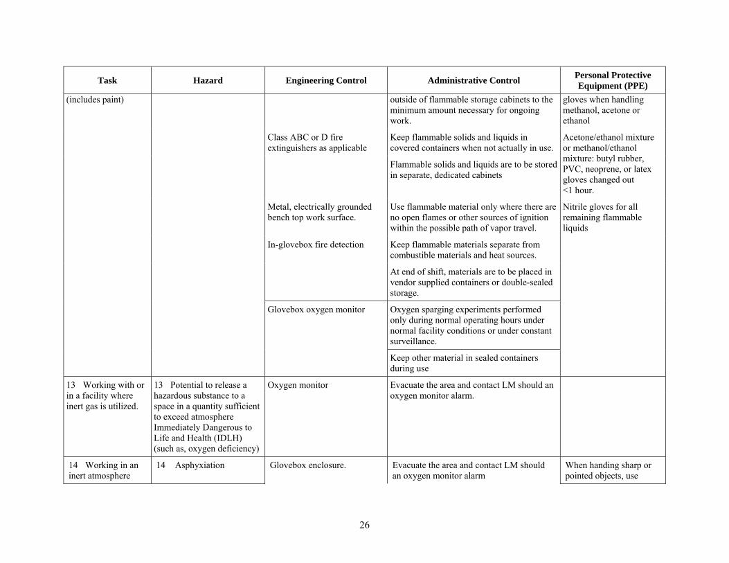
Task Hazard Engineering Control Administrative Control Personal Protective Equipment (PPE)
or defects prior to use. Remove defective or damaged tools and cords.
Test the GFCI for proper operation prior to use.
Wear sturdy leather shoes.
Use extension cords (if needed) with adequately sized wire in accordance with manufacturer's instructions.
Wear ANSI Level IV cut-resistant gloves when using knives or handling metal objects with sharp edges, as deemed necessary by the operator.
6. Use of abrasive-disk or cutting type saw
6. Cuts or burns, Eye injuries, Noise, Hazardous airborne particulates.
Ensure manufacturer’s machine guarding and work piece holder are in place and operational
Read and follow vendor instruction manual. Safety glasses with side shields
Keep loose clothing, hair, jewelry, badge, etc. from becoming entangles.
Wear substantial shoes.
Never secure or unsecure material in the work piece holder while the abrasive disk is rotating. Stand to one side when first starting the saw.
Wear ANSI Level IV cut resistant gloves when handling sharp or rough material as deemed necessary by the operator.
Keep hands away from the abrasive wheel or cutting blade at all times.
Wear leather gloves when handling hot cut materials.
Do not become distracted while operating the saw.
Hearing protection as required
Contact Industrial Hygiene (IH) for an initial assessment of the dust and noise levels generated by this work activity. Implement any control measures as directed by IH and as required by the IH exposure assessment.
Use full face shield & safety glasses if flying particle hazard exists.
Replace abrasive disks or blade must be inspected and ring tested (if applicable) before attachment to the saw.

24
Task Hazard Engineering Control Administrative Control Personal Protective Equipment (PPE)
The maximum operating speed rating of an abrasive disk must be greater than the spindle speed of the saw.
The thin abrasive disk or blade can shatter if stressed or damaged. Always cut with the edge (circumference) of the blade. Never press a work piece against the side of the blade.
7 Using rotating / crushing/ grinding equipment
7a Pinch points Use proper equipment guards (hoppers).
Use proper hand/finger positioning. Wear leather gloves when appropriate
7b Contact with moving parts resulting in lacerations, abrasions and or incisions.
Use proper equipment guards (hoppers).
Read and follow vendor instruction manuals. Safety glasses with side shields.
Be aware of surroundings.
Ensure machine guarding is in place prior to start up.
Make sure that equipment and personnel cannot become entangled.
Remove or secure loose clothing, security badge, neckties, jewelry, long hair or other items that can become entangles in moving parts, badge, etc. from becoming entangles.
Make sure body, hand, finger positioning is clear of moving or rotating equipment.
Barricade work area while working with rotational equipment and post to keep unnecessary personnel away from hazards.
Do not use rags near rotating equipment.
8 Chemical Handling (Includes hazards
8a Skin irritations and burns
An emergency eyewash station is located in the west room of bldg. 789.
Review and be familiar with the MSDS for chemicals used for this project.
Safety Glasses with side shields, Lab coat, Substantial footwear

25
Task Hazard Engineering Control Administrative Control Personal Protective Equipment (PPE)
common to preparation, cleaning, transfers and storage)
A sink is located in the west room of bldg. 789.
Contact Industrial Hygiene for an exposure assessment prior to using any new chemicals not yet identified in this LI.
Nitrile gloves for all other chemical handling unless otherwise noted in this table.
Gloveboxes (for handling particularly hazardous substances, volatile chemicals or chemicals that present a significant airborne hazard.)
Establish adequate work space for containers to be used.
Neoprene gloves or equivalent when handling corrosive acids or chemicals.
Keep flammable solids and liquids in covered containers when not actually in use.
Nitrile or neoprene gloves for cleaning agents injurious to eyes or skin
Include a face shield or chemical goggles and a laboratory apron if the following scenario(s) exist:
1) Pouring solutions when containers cannot be easily handled with one hand and/or when there is a potential for splashing.
2) When performing pressurized transfers.
8b Unintended chemical reactions
Emergency shower/eyewash station
Always add acid to water, adding water to acid may result in a violent reaction
Use distance between incompatible solutions to prevent inadvertent splashing or mixing (refer to MSDS for chemical incompatibilities).
9 Working with flammable solid, liquid, or vapors
9 Fire hazard from vapors and/or handling flammable materials
Use only in ventilated areas. Use spark resistant (e.g. brass) tools and containers while handling or storing.
Safety glasses with side shields
Keep quantities of flammable materials Butyl rubber or neoprene
26
Task Hazard Engineering Control Administrative Control Personal Protective Equipment (PPE)
(includes paint) outside of flammable storage cabinets to the minimum amount necessary for ongoing work.
gloves when handling methanol, acetone or ethanol
Class ABC or D fire extinguishers as applicable
Keep flammable solids and liquids in covered containers when not actually in use.
Acetone/ethanol mixture or methanol/ethanol mixture: butyl rubber, PVC, neoprene, or latex gloves changed out <1 hour.
Flammable solids and liquids are to be stored in separate, dedicated cabinets
Metal, electrically grounded bench top work surface.
Use flammable material only where there are no open flames or other sources of ignition within the possible path of vapor travel.
Nitrile gloves for all remaining flammable liquids
In-glovebox fire detection Keep flammable materials separate from combustible materials and heat sources.
At end of shift, materials are to be placed in vendor supplied containers or double-sealed storage.
Glovebox oxygen monitor Oxygen sparging experiments performed only during normal operating hours under normal facility conditions or under constant surveillance.
Keep other material in sealed containers during use
13 Working with or in a facility where inert gas is utilized.
13 Potential to release a hazardous substance to a space in a quantity sufficient to exceed atmosphere Immediately Dangerous to Life and Health (IDLH) (such as, oxygen deficiency)
Oxygen monitor Evacuate the area and contact LM should an oxygen monitor alarm.
14 Working in an inert atmosphere
14 Asphyxiation Glovebox enclosure. Evacuate the area and contact LM should an oxygen monitor alarm
When handing sharp or pointed objects, use

27
Task Hazard Engineering Control Administrative Control Personal Protective Equipment (PPE)
glovebox Oxygen monitor Regularly inspect gloves for defects. leather gloves to protect glovebox gloves whenever possible. Gas regulator Read and follow vendor instruction manual
Use the proper tool for the application. Avoid excessive force. Avoid placing hands in positions where tool slippage can result in glove breach.
Inspect the tools to ensure there are no defects.
Prior to service operations on power tools (such as replacing blades, discs, bits, and other attachments), disconnect the tool from its power source (electrical outlet, air hose, etc.) and maintain control over the power source.
Cover sharp points and edges when not in use.
15 Breaking the boundary or assembling a nonflammable gas system
15 Release of high-pressure gas.
A suitable pressure relief device shall be sized and used to protect a pressure system where the system has a MAWP, or design pressure rating less than the pressure supply source, or where there is a possibility of exceeding the system pressure rating.
Ensure the Maximum Allowable Working Pressure (MAWP) for all components and equipment exceeds the maximum operating pressure for the system.
Wear safety glasses with side shields during venting of pressure.
Do not use volatile or flammable cleaning fluids to clean parts to be used in compressed air systems. After cleaning, all parts shall be rinsed and dried.
The pressure device shall be vented to a safe location.
16 Maintenance that may encompass an electrical hazard
16 Electrical shock No work on energized equipment >50 V is to be performed under this package.
Whenever possible, minor repairs on equipment (e.g., changeout of failed heating elements) shall be done on deenergized

28
Task Hazard Engineering Control Administrative Control Personal Protective Equipment (PPE)
equipment. This will be done with exclusive control of plug.
Meter reading on <50 volts exposure is to be done only by Research and Electronic Worker trained or exemption trained personnel.
Keep unauthorized personnel out of area
Ensure area around panel is clear of all materials with no moisture.
Wear non-melting or untreated natural-fiber long pants with min. fabric weight of 4.5 oz/yd2.
Verify ALL personnel are clear of the default flash protection boundary (4 feet).
Wear safety glasses with side shields.
Notify LM prior to operation. Wear leather gloves (recommended).
Ensure the weight of the load is known and it is within the capacity of the equipment (i.e. crane/hoist/rigging).
Verify that the floor load rate will not be exceeded.
Ensure that other personnel in the area are aware of impending load movements.
Do not leave suspended load unattended
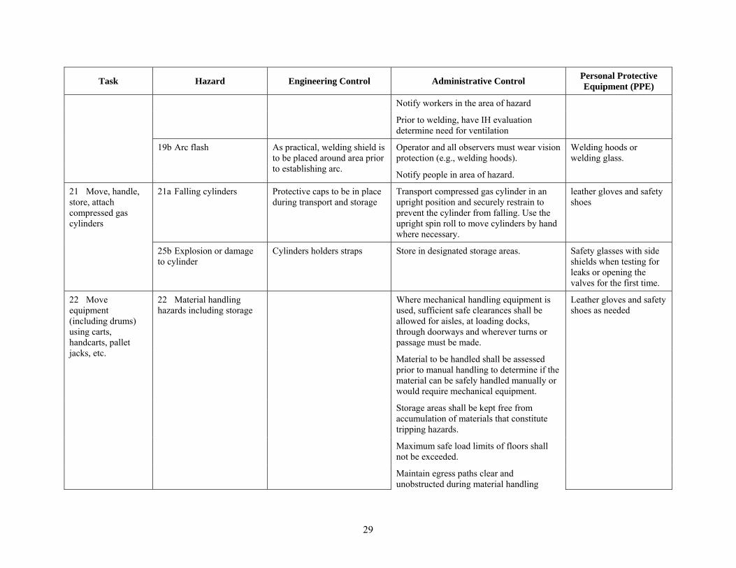
19 Welding, cutting, flame soldering, grinding, or plasma arc cutting or otherwise producing sparks or flames.
19a Fire or burns. Building fire alarm Follow non designated Hot Work Area Permit.
PPE as specified in non designated hot work area permit
Portable rated fire extinguisher.
The material is to be allowed to cool prior to handling without tools or insulated gloves.
Portable exhaust Post sign warning of operations
29
Task Hazard Engineering Control Administrative Control Personal Protective Equipment (PPE)
Notify workers in the area of hazard
Prior to welding, have IH evaluation determine need for ventilation
19b Arc flash As practical, welding shield is to be placed around area prior to establishing arc.
Operator and all observers must wear vision protection (e.g., welding hoods).
Welding hoods or welding glass.
Notify people in area of hazard.
21 Move, handle, store, attach compressed gas cylinders
21a Falling cylinders Protective caps to be in place during transport and storage
Transport compressed gas cylinder in an upright position and securely restrain to prevent the cylinder from falling. Use the upright spin roll to move cylinders by hand where necessary.
leather gloves and safety shoes
25b Explosion or damage to cylinder
Cylinders holders straps Store in designated storage areas. Safety glasses with side shields when testing for leaks or opening the valves for the first time.
22 Move equipment (including drums) using carts, handcarts, pallet jacks, etc.
22 Material handling hazards including storage
Where mechanical handling equipment is used, sufficient safe clearances shall be allowed for aisles, at loading docks, through doorways and wherever turns or passage must be made.
Leather gloves and safety shoes as needed
Material to be handled shall be assessed prior to manual handling to determine if the material can be safely handled manually or would require mechanical equipment.
Storage areas shall be kept free from accumulation of materials that constitute tripping hazards.
Maximum safe load limits of floors shall not be exceeded.
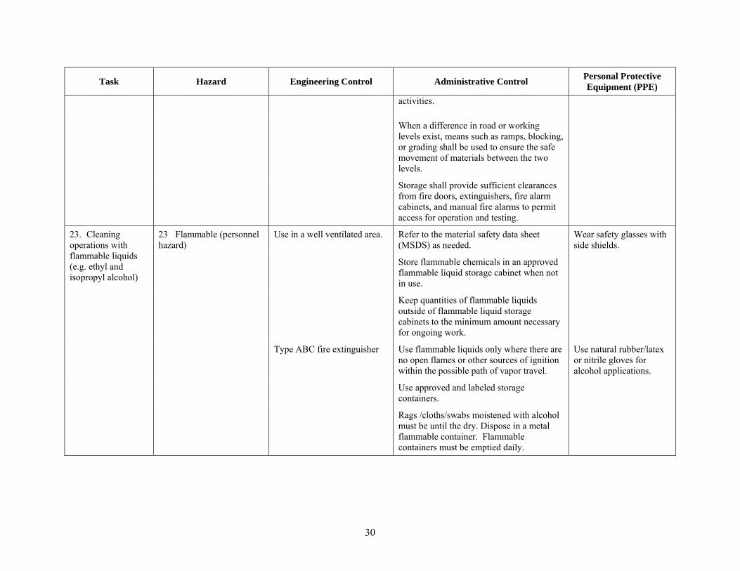
Maintain egress paths clear and unobstructed during material handling
30
Task Hazard Engineering Control Administrative Control Personal Protective Equipment (PPE)
activities.
When a difference in road or working levels exist, means such as ramps, blocking, or grading shall be used to ensure the safe movement of materials between the two levels.
Storage shall provide sufficient clearances from fire doors, extinguishers, fire alarm cabinets, and manual fire alarms to permit access for operation and testing.
23. Cleaning operations with flammable liquids (e.g. ethyl and isopropyl alcohol)
23 Flammable (personnel hazard)
Use in a well ventilated area. Refer to the material safety data sheet (MSDS) as needed.
Wear safety glasses with side shields.
Store flammable chemicals in an approved flammable liquid storage cabinet when not in use.
Keep quantities of flammable liquids outside of flammable liquid storage cabinets to the minimum amount necessary for ongoing work.
Type ABC fire extinguisher Use flammable liquids only where there are no open flames or other sources of ignition within the possible path of vapor travel.
Use natural rubber/latex or nitrile gloves for alcohol applications.
Use approved and labeled storage containers.
Rags /cloths/swabs moistened with alcohol must be until the dry. Dispose in a metal flammable container. Flammable containers must be emptied daily.

31
Table 3. Hazard scenarios that require mitigation.
Hazard Mitigation
Operator Distraction Nonessential personnel in the area may prove to be a distraction to the operator comprising both quality and safety. Excess personnel may be asked to leave at the discretion of the operator or the principal investigator.
Arc Flash Hazard Shielding shall be used to prevent arc-flash exposure to bystanders whenever practical. In some instances, shielding cannot be practically used (e.g. when the shielding restricts the available light needed by the operator). In such cases mitigations may include, signs and verbal warnings.
Area Oxygen Monitor Alarm
To mitigate against asphyxiation hazard, if an area oxygen monitor alarms, all personnel shall exist the facility and contact the Laboratory Manager.
Table 4. Waste types and disposal methods.
Type of Waste Generation
Location Anticipated
Volume Container
Type Disposal Method
Industrial Waste (for example, non-flammable, non-RCRA wastes, zéolite, glass, and rags with commercial glass cleaner).
MFC, Building 789
<25 kg per month
Plastic bags If less than 5kg, managed as industrial waste for landfill disposal. If greater than 5kg, deliver to Waste Generator Services (WGS) at building 706 South.
Liquid solutions (Acids or flammable liquids)
MFC, Building 789
<20 L per year
Compatible container such as poly bottles
Store in the established SAA until the waste is ready for disposition by WGS.
Liquid solutions (non-radiological, non-hazardous)
MFC, Building 789
<1 m3 Poly bottle Environmental Support personnel must be evaluate and approve all non-radiological, non-hazardous effluent discharges to the industrial or sanitary waste system.
Rags/wipes used with alcohol/ethanol for cleaning operations
MFC, Building 789
<1 m3 Metal can Rags/cloths/swabs moistened with alcohol/ethanol must be used until the dry. Dispose in an approved flammable material container after use. Flammable containers must be emptied daily. If wipes are not used until dry, the wipes must be managed as a hazardous waste and stored in a Satellite Accumulation Area (SAA).
List any special needs/requirements for storage and handling wastes.
Non-flammable materials will be stored and handled in sealed containers. RCRA and non-RCRA materials will be separated as much as reasonably possible.
Flammable metals will be double sealed with a metal outer container.
If a spill occurs, how will it be cleaned up?
To ensure the proper actions are taken for each step of the Laboratory’s spill response process, the following process will be followed:
STOP the spill if safe to do so. If not able to safely stop the spill, warn others in the immediate area and evacuate

32
Type of Waste Generation
Location Anticipated
Volume Container
Type Disposal Method
to a safe location. Notify the LM and emergency services.
WARN others in the surrounding area of the spill. Let people around know what is going on. If the situation warrants, evacuate the area. Secure work tasks.
ISOLATE the area sufficient to prevent personnel inadvertently entering the spill area.
NOTIFY the LM or their delegate and others as necessary. The LM will control the response to the spill. This includes small spills that can be safely managed by any individual.
AWAIT INSTRUCTIONS. The LM will assess the spill and determine the correct response. If no special assistance is needed the LM may authorize researchers, facility technicians, etc., to clean up the spill. Note that researchers are authorized to clean up small spills of laboratory chemicals (consisting of a few milliliters) that can be performed with chemical wipes anywhere in the facility.
LM RELEASES WORK. Once the spill and spill hazards have safely been mitigated, the LM will release the paused work.
Dry materials are collected with brush and dustpan. Wet materials will be collected with terry towels which will be collected in a bag for proper disposal.
Once the spill is under control, contact WGS for disposal requirements.
If a spill/release occurs outside a properly designed, constructed, and maintained containment, contact the Spill Notification Team by one of the following methods: cell phone number 241-6400, pager system - dial 526-4444, pager #6400 and enter a phone number for the Spill Notification Team to call back, or call the Warning Communications Center at 526-1515, and request they notify the Spill Notification Team.
Describe anything else that may be relevant for waste disposal purposes.
Contact WGS for proper storage and disposal requirements of any waste generated that is not identified in Table 2.03, waste generation.
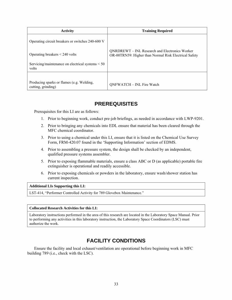
Table 5. Training required
Activity Training Required
Working in an R&D Laboratory 00INL670, “R&D Laboratory Awareness Training”
00INL722, “Laboratory Personal Protective Equipment”
Working with chemicals
000INL13, “Chemical Hygiene Plan”
00INL722, “Laboratory Protective Equipment”
SMJS992B, “Flammable & Combustible Materials”
SMJS992E, “Irritants, Corrosives and Sensitizers”
SMJS992P, “Chemicals with Specific Target Organ Effects”
SMJS992Q, “Particularly Hazardous Substances”
SMJS992S, “Agents Present Significant Exposure via Inhalation/Absorption”
Work with compressed gas cylinders 0TRN1041, “Compressed Gas Safety”
Pressure system assembly QN000PSA, BEA Pressure System Assembler
Pressure system review
Working with electronics QNRDREWT, “INL Research and Electronics Worker”
33
Activity Training Required
Operating circuit breakers or switches 240-600 V
QNRDREWT – INL Research and Electronics Worker OR-00TRN59: Higher than Normal Risk Electrical Safety Operating breakers < 240 volts
Servicing/maintenance on electrical systems < 50 volts
Producing sparks or flames (e.g. Welding, cutting, grinding)
QNFWATCH – INL Fire Watch
PREREQUISITES Prerequisites for this LI are as follows:
1. Prior to beginning work, conduct pre-job briefings, as needed in accordance with LWP-9201.
2. Prior to bringing any chemicals into EDL ensure that material has been cleared through the MFC chemical coordinator.
3. Prior to using a chemical under this LI, ensure that it is listed on the Chemical Use Survey Form, FRM-420.07 found in the ‘Supporting Information’ section of EDMS.
4. Prior to assembling a pressure system, the design shall be checked by an independent, qualified pressure systems assembler.
5. Prior to exposing flammable materials, ensure a class ABC or D (as applicable) portable fire extinguisher is operational and readily accessible.
6. Prior to exposing chemicals or powders in the laboratory, ensure wash/shower station has current inspection.
Additional LIs Supporting this LI:
LST-414, “Performer Controlled Activity for 789 Glovebox Maintenance.”
Collocated Research Activities for this LI:
Laboratory instructions performed in the area of this research are located in the Laboratory Space Manual. Prior to performing any activities in this laboratory instruction, the Laboratory Space Coordinators (LSC) must authorize the work.
FACILITY CONDITIONS Ensure the facility and local exhaust/ventilation are operational before beginning work in MFC
building 789 (i.e., check with the LSC).

34
INSTRUCTIONS No radiological or highly hazardous activities are to be used under this LI.
POST-PERFORMANCE ACTIVITIES Ensure chemicals and/or equipment is properly labeled and stored prior to leaving the work area.
Properly dispose of waste per Table 2.03.
Store all equipment, tools and non-waste materials properly for use in future experiments
Excess equipment as appropriate
ABNORMAL OPERATIONS NOTE: Operations will not proceed under abnormal conditions unless approved by the Laboratory
and/or Facility Manager, as appropriate, and the work remains within the bounds of this Laboratory Instruction.
1. If an abnormal situation or alarm is observed in the facility all personnel shall exist the facility and obtain the Laboratory Manager permission before re-entering the facility.
2. If glovebox oxygen levels exceed 50 ppm, turn off glovebox gas recirculation system and commence corrective actions.
3. If glovebox temperature exceeds 40°C, turn off glovebox gas recirculation system, turn off all heat generating equipment, and commence corrective actions.
4. Area Oxygen Monitor Alarm
NOTE: Building 789 is large and is not leak tight. Fans are used to circulate the air in the room. The flow of argon gas into the system is regulated and therefore, reduces the chance of a large release. As a conservative measure, the facility is equipped with multiple area oxygen monitors and all are on a quarterly PM schedule. There is one monitor in the East room permanently mounted to the wall. The other monitors are portable and can be moved. Due to the conservative nature of the monitors, it is anticipated a monitor will alarm while in service.
a) If an area oxygen monitor alarms all personnel shall exist the facility and contact the Laboratory Manager.
b) The Laboratory Manager may use a calibrated hand held oxygen monitor and slowly enter the facility.
c) If the hand held oxygen monitor alarms the Laboratory Manager shall exit the facility and contact Industrial Hygiene.
d) If the hand held oxygen monitor DOES NOT alarm, the Laboratory Manager may continue walking through the facility until the alarming monitor is located then reset, or re-calibrated, or removed from service.
RECORDS Records will be held in laboratory notebooks and project files in compliance with MFC regulation,
MCP-2875, “Maintaining Laboratory Notebooks,” and general standard procedures. All process data shall be recorded as directed by the sponsoring program.

35
Daily R&D and general work activities will be documented on program specific activity sheets or in Laboratory Notebooks that list pertinent job specifications, process steps, and data verification requirements. Records and retention periods are listed in Table 6.
Table 6. Records and retention periods.
Records Description Uniform File Code
Disposition Authority
Retention Period
Project case files for general work activities that are not electrochemical experiments
8406 RD1-A-2 Level II: Cutoff after project/program completion, cancellation or termination. Destroy 25 years after termination of project/program.
NOTE: Records identified with an epidemiological stamp (EPI) must not be destroyed.
REFERENCES Operating Manuals
LWP-14620, “Chemical Hygiene Plan”
MCP-2875, “Maintaining Laboratory Notebooks”
FRM 420.07, “Chemical Use Survey Form” see “supporting information” in edms
APPENDICES Appendix A

36
Appendix A The following sample instructions are for Weld Development Research Projects and can be utilized as
written or changed at the discretion of the project.
NOTE 1: Weld development requires some assembly work and welding. This includes using hand tools to assemble equipment, route wires, etc. The data logging components, controllers, and other electronics requires adjustments or repairs. A typical fabrication activity may follow the following steps, but the researcher may change the order as well as add or remove steps as needed if no additional hazards are added.
NOTE 2: Section 2 contains engineering controls, administrative controls, and PPE requirements and should be reviewed prior to performance.
1. Assemble the welding fixture,
1.1 Fabricate welding fixture components in a machine shop for assembly and disassembly in building 789.
1.2 Set up welder to complete the desired welding task. This includes changing cables, torches and adding a shunt attachment to measure the voltage and ampere used during welding.
2. Perform the welding
2.1 Obtain facility manager approval before energizing the 480 volt disconnect switch.
2.2 Energize the 480 volt power supply following the procedure. This includes both the energizing and de-energizing.
2.3 Connect and turn on the argon shielding gas cylinder
2.4 Program the power supply
2.5 Place test parts into welding fixture and perform adjustments as per project specifications.
2.6 Perform welding covered with a Designated Area Hot Work Permit.
2.7 Allow test parts to cool to ≤ 50º C or handled with appropriate PPE and or extension tools.
2.8 Use the remote vision system to the welding fixture for visualizing the position of the torch relative to the end plug as needed.
2.9 Use the data acquisition system of the welding system package as needed. A laptop or PC with monitors supplements the data acquisition package. The data generates from a shunt installed at the welding cable connection of the power supply.
3. Conduct lab data entry work
3.1 Record welding schedule data
3.2 Record visual inspection notes as needed

37
Appendix B
Technical / Functional Requirements Matrix

38
Appendix B Technical / Functional Requirements Matrix
Time Line No.
Technical / Functional Requirement Basis
5 Update project plan
7 Define the system components Required to know what to purchase
8 Generate a draft sketch Sketch is needed for the technicians to build the system and for knowing the foot print
9 Purchase components for mock-up remote welding system
Need the parts for mock-up, but parts are to be considered for the in-cell system
9 Acquire torch stand to support positioners and torch This configuration is required to mimic the in-cell system.
9 Acquire electronic data acquisition system Data for quality assurance package
9 Acquire a remote vision system with 10X magnification Remote system shall be required for the in-cell inspection and imaging system
10 Construct mock-up of preliminary remote welding system
This project milestone by 12/2012
11 A remote vision system shall align the electrode and end plug at a 10X magnification
This provides an adequate resolution for the inspection
11 GTAW power supply system must demonstrate consistent arc starting
Historical problem in prior years
11 GTAW power supply system include HF or capacitor discharge arc starting system
These are the only options for in-cell work
11 A remote vision system shall quantitatively measure profile of the finished welded plug and porosity inspection
Profile data needed for quality assurance
16 Validate the inspectability of the redesigned tapered end plugs: two sizes and materials
Conduct X-ray analysis of weld to ascertain weld metal penetration into internal grove
16 Write a qualification plan Need a qualification plan for final report
16 Conduct preliminary HT9 qualifications HT9 quals are for the 0.230 diameter tubes
16 Conduct preliminary 316 SS qualification 316 quals are for the 0.3125 diameter tubes
16 Conduct operator qualifications Generate an operator qual based on the material quals
17 Report results of testing and qualifications Present the testing and qualification findings
18 Report project lessons learned Capture the lessons learned for the next project phase
18 Capture and report path forward details, sketches, or designs for subsequent in-cell system construction
Report the path forward intellectual knowledge for the next project phase
19 A digital image of the welded end plug profiles shall be captured
Data for quality assurance package
19 A database of welded end plug profiles photographs shall be developed for reference comparison of finished welds
Profile data needed for quality assurance comparisons

39
Appendix C
Trade Study

40
Appendix C Trade Study
Criteria:
Cost of Welding System is defined as the cost purchase a total functioning welding system to perform the closure welds.
Deployable in Hot Cell is defined as the time needed to replace the equipment, item or personnel. Foot Print of Welding System is defined as an estimate on in increase of productivity if the HFEF hot cell piece of equipment, item or personnel were replaced or added.
Weight is the multiplier value that is arbitrarily defined by the project team to represent a weight factor of importance to the criteria. The weight values are between 1 to 7 with 7 being the best.
Value Ranking is a decompositional breakdown that provides a range of values or basis for ranking the Limitation with the Criteria.
Score is the product of the Weight and the Value of each Criterion. Total is the sum of all scores for each Limitation. The highest score wins as most important.
No. Criteria
Weight (1 to 7 with 7 as best)
Value Ranking
Value (1 to 12
with 12 as best)
1 2 3
Gas Tungsten Arc Welding
Laser Welding Resistance Butt Welding
Wt X Value = Score Wt X Value = Score Wt X Value = Score
1 Cost of
Welding System
3
<$5,000 12
<$
5,00
0
36 >
$30,
000
3
>$3
0,00
0
3 $5,000 to $10,000
8
$20,000 to $30,000
4
>$30,000 1
2 Deployable in
Hot Cell 7
Easy 12
E
asy 84
Dif
ficu
lt
28 L
ots
of
Eff
ort
7 Doable 8Difficult 4
Lots of Effort 1
3
In-Cell Foot Print of Welding System
6
<2 ft2 12
<2
ft2
72 2
to 4
ft2
48
>6ft
2
6 2 to 4 ft2 8
4 to 6 ft2 4
>6ft2 1
Totals --- 130 --- 79 --- 16

41
Appendix D
Photographs of the Mock-up Welding System

42
Appendix D Photographs of the Mock-up Welding System
Data acquisition screen data
Data acquisition controller
Prototype welding station
Miller MaxStar Power supply
Collet holder with handle
XY precision slides
Torch with electrode
Tube adjustment positioning bolt

43
Appendix E
Components for Welding Coupons

44
Appendix E Components for Welding Coupons
Table showing end plugs, cladding pieces, electrodes, end plug press, and other supplies
End plugs and HT9 tubes ready for welding
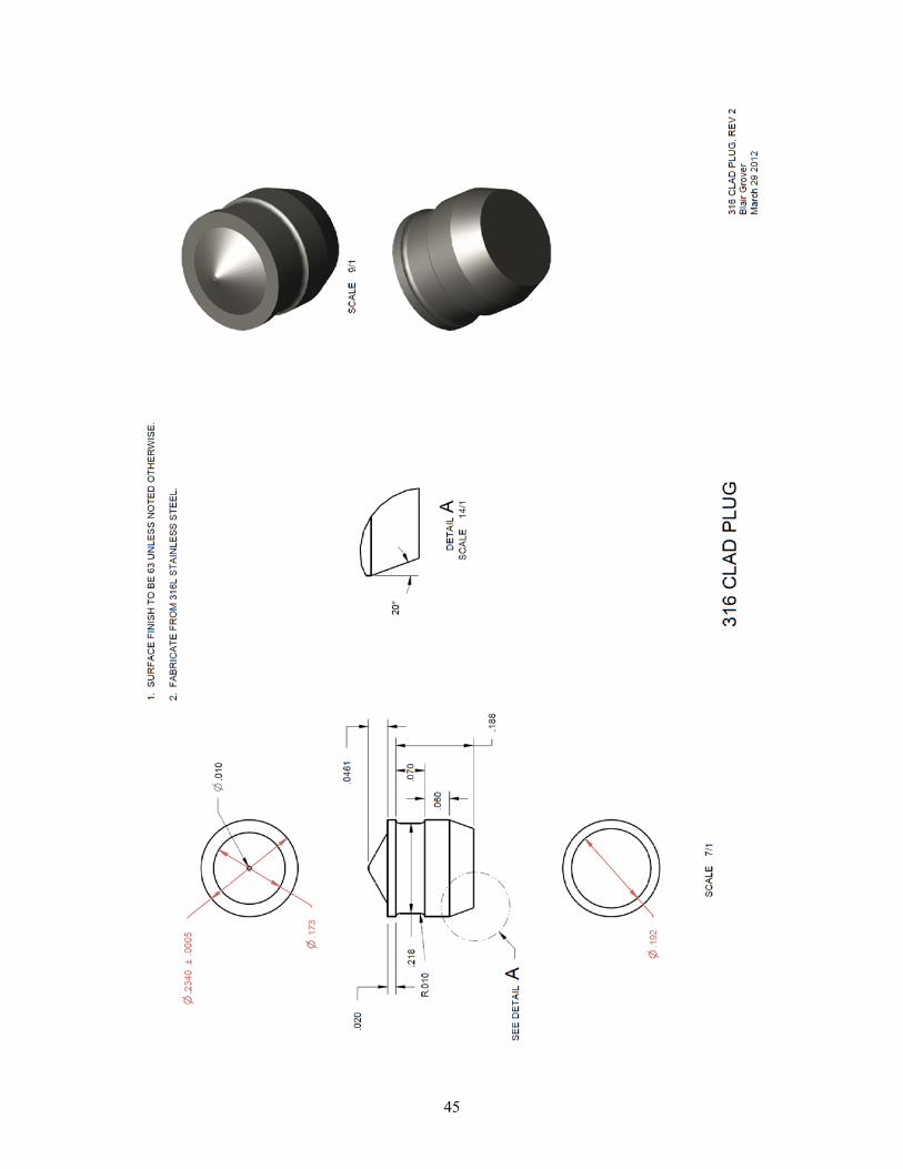
45

46

47
Appendix F
Welding Parameters

48
Appendix F Welding Parameters
Photograph showing an arc starting on an end plug
Close up photograph of a end plug cooling after welding
Photograph showing the pre-sharpened and polished rare earth oxide tungsten electrodes
An early 316 stainless weld with 0.030 X 0.060-inch X-ray relief. Excellent penetration, but this wide of a relief was reduced to mediate blow outs in the closure welds
Welded end plug that is discolored because of the lack of shielding after welding

49
End plug set into copper chill block before welding
End plug set into copper chill block with the 0.040-inch thick spacer gauge setting the arch length before welding
An excellent shape on a welded end plug that was welded in a collet.
Weld Development Project Welder ‐ Miller Maxstar 300 LX 4/13/2012
WELD MATERIAL: HT9 DIAMETER: THICKNESS: LENGTH:
DATE: 4/13/2012 4/13/2012 4/13/2012 4/13/2012 4/13/2012 4/13/2012 4/13/2012 4/13/2012 4/13/2012 4/13/2012
MEMORY: Schedule 1 1 1 1 1 1 1 1 1 1
WELD NUMBER: P#‐75 P#‐76 P#‐77 P#‐78 P#‐79 P#‐80 P#‐81 P#‐82 P#‐83 P#‐84
MAIN PEAK (AMPS) 245 245 245 245 245 245 245 245 245 245
MAIN PEAK (SECS) 0.2 0.2 0.2 0.2 0.2 0.2 0.2 0.2 0.2 0.2
PROCESS: TIG HF IMPULSE TIG HF IMPULSE TIG HF IMPULSE TIG HF IMPULSE TIG HF IMPULSE TIG HF IMPULSE TIG HF IMPULSE TIG HF IMPULSE TIG HF IMPULSE TIG HF IMPULSE
OUTPUT: RMT 2T Hold RMT 2T Hold RMT 2T Hold RMT 2T Hold RMT 2T Hold RMT 2T Hold RMT 2T Hold RMT 2T Hold RMT 2T Hold RMT 2T Hold
PULSER:
PULSER PPS (Hz) 20 20 20 20 20 20 20 20 20 20
PULSER PEAK t (%) 95 95 95 95 95 95 95 95 95 95
PULSER BKGND A (%) 95 95 95 95 95 95 95 95 95 95
SEQUENCER:
INITIAL A (Amp) 5 5 5 5 5 5 5 5 5 5
INITIAL A (Sec) 0.1 0.1 0.1 0.1 0.1 0.1 0.1 0.1 0.1 0.1
INITIAL SLOPE t (Sec) 0.1 0.1 0.1 0.1 0.1 0.1 0.1 0.1 0.1 0.1
FINAL SLOPE t (Sec) 0.1 0.1 0.1 0.1 0.1 0.1 0.1 0.1 0.1 0.1
FINAL A (amp) 5 5 5 5 5 5 5 5 5 5
FINAL A (Sec) 0.1 0.1 0.1 0.1 0.1 0.1 0.1 0.1 0.1 0.1
ADJUST:
PREFLOW (Sec) 5 5 5 5 5 5 5 5 5 5
POSTFLOW (Sec) 15 15 15 15 15 15 15 15 15 15
ARGON Pressure
ARGON Flow (CFH) 30 30 30 30 30 30 30 30 30 30
GAP: (thousandths) 40 40 40 40 40 40 40 40 40 40
NOTES:
Basic welding parameters for HT9 0.230 diameter tubing
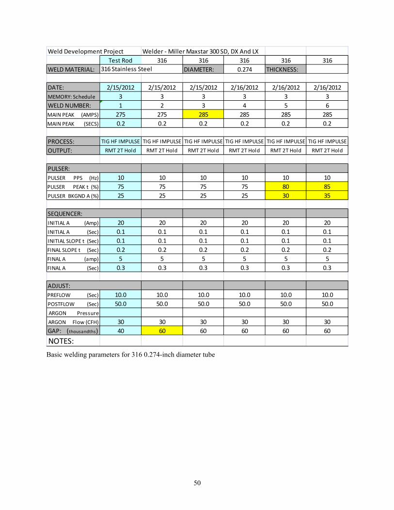
50
Weld Development Project Welder ‐ Miller Maxstar 300 SD, DX And LX
Test Rod 316 316 316 316 316
WELD MATERIAL: DIAMETER: 0.274 THICKNESS:
DATE: 2/15/2012 2/15/2012 2/15/2012 2/16/2012 2/16/2012 2/16/2012
MEMORY: Schedule 3 3 3 3 3 3
WELD NUMBER: 1 2 3 4 5 6
MAIN PEAK (AMPS) 275 275 285 285 285 285
MAIN PEAK (SECS) 0.2 0.2 0.2 0.2 0.2 0.2
PROCESS: TIG HF IMPULSE TIG HF IMPULSE TIG HF IMPULSE TIG HF IMPULSE TIG HF IMPULSE TIG HF IMPULSE
OUTPUT: RMT 2T Hold RMT 2T Hold RMT 2T Hold RMT 2T Hold RMT 2T Hold RMT 2T Hold
PULSER:
PULSER PPS (Hz) 10 10 10 10 10 10
PULSER PEAK t (%) 75 75 75 75 80 85
PULSER BKGND A (%) 25 25 25 25 30 35
SEQUENCER:
INITIAL A (Amp) 20 20 20 20 20 20
INITIAL A (Sec) 0.1 0.1 0.1 0.1 0.1 0.1
INITIAL SLOPE t (Sec) 0.1 0.1 0.1 0.1 0.1 0.1
FINAL SLOPE t (Sec) 0.2 0.2 0.2 0.2 0.2 0.2
FINAL A (amp) 5 5 5 5 5 5
FINAL A (Sec) 0.3 0.3 0.3 0.3 0.3 0.3
ADJUST:
PREFLOW (Sec) 10.0 10.0 10.0 10.0 10.0 10.0
POSTFLOW (Sec) 50.0 50.0 50.0 50.0 50.0 50.0
ARGON Pressure
ARGON Flow (CFH) 30 30 30 30 30 30
GAP: (thousandths) 40 60 60 60 60 60
NOTES:
316 Stainless Steel
Basic welding parameters for 316 0.274-inch diameter tube
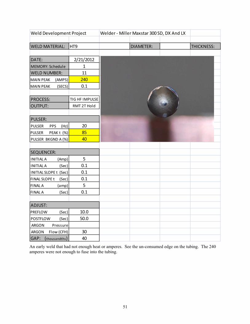
51
Weld Development Project Welder ‐ Miller Maxstar 300 SD, DX And LX
WELD MATERIAL: HT9 DIAMETER: THICKNESS:
DATE: 2/21/2012
MEMORY: Schedule 1
WELD NUMBER: 11
MAIN PEAK (AMPS) 240
MAIN PEAK (SECS) 0.1
PROCESS: TIG HF IMPULSE
OUTPUT: RMT 2T Hold
PULSER:
PULSER PPS (Hz) 20
PULSER PEAK t (%) 85
PULSER BKGND A (%) 40
SEQUENCER:
INITIAL A (Amp) 5
INITIAL A (Sec) 0.1
INITIAL SLOPE t (Sec) 0.1
FINAL SLOPE t (Sec) 0.1
FINAL A (amp) 5
FINAL A (Sec) 0.1
ADJUST:
PREFLOW (Sec) 10.0
POSTFLOW (Sec) 50.0
ARGON Pressure
ARGON Flow (CFH) 30
GAP: (thousandths) 40
An early weld that had not enough heat or amperes. See the un-consumed edge on the tubing. The 240 amperes were not enough to fuse into the tubing.

52
Weld Development Project Welder ‐ Miller Maxstar 300
LENGTH:
THICKNESS: 1/8"
DIAMETER:
WELD MATERIAL: SS Plate
DATE: 3/21/2012
MEMORY: Schedule 1
WELD NUMBER: SS Plate 2
MAIN PEAK (AMPS) 250
MAIN PEAK (SECS) 0.2
PROCESS: TIG HF IMPULSE
OUTPUT: RMT 2T Hold
PULSER:
PULSER PPS (Hz) 20
PULSER PEAK t (%) 95
PULSER BKGND A (%) 90
SEQUENCER:
INITIAL A (Amp) 5
INITIAL A (Sec) 0.1
INITIAL SLOPE t (Sec) 0.0
FINAL SLOPE t (Sec) 0.1
FINAL A (amp) 5
FINAL A (Sec) 0.1
ADJUST:
PREFLOW (Sec) 1.0
POSTFLOW (Sec) 3.0
ARGON Pressure
ARGON Flow (CFH) 30 Bottom of SS Plate
GAP: (thousandths) 40
NOTES:
Spot weld on a piece of 0.062-inch thick stainless steel with 250 amperes show more penetration with 0.040-in arc length. The small insert photo below the spot weld shows the penetration through the thickness.
Weld Development Project Welder ‐ Miller Maxstar 300
LENGTH:
THICKNESS: 1/8"
DIAMETER:
WELD MATERIAL: SS Plate
DATE: 3/21/2012
MEMORY: Schedule 1
WELD NUMBER: SS Plate 5
MAIN PEAK (AMPS) 250
MAIN PEAK (SECS) 0.2
PROCESS: TIG HF IMPULSE
OUTPUT: RMT 2T Hold
PULSER:
PULSER PPS (Hz) 20
PULSER PEAK t (%) 95
PULSER BKGND A (%) 90
SEQUENCER:
INITIAL A (Amp) 5
INITIAL A (Sec) 0.1
INITIAL SLOPE t (Sec) 0.0
FINAL SLOPE t (Sec) 0.1
FINAL A (amp) 5
FINAL A (Sec) 0.1
ADJUST:
PREFLOW (Sec) 1.0
POSTFLOW (Sec) 3.0
ARGON Pressure
ARGON Flow (CFH) 30 Bottom of SS Plate
GAP: (thousandths) 60
NOTES:
Spot weld with 250 amperes show less penetration with 0.060-in arc length. The insert photograph shows no melt through on the back side of the sheet metal.

53
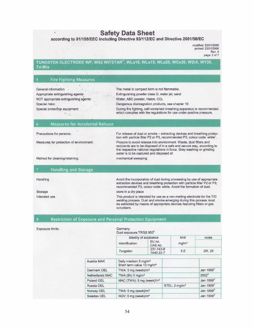
54

55
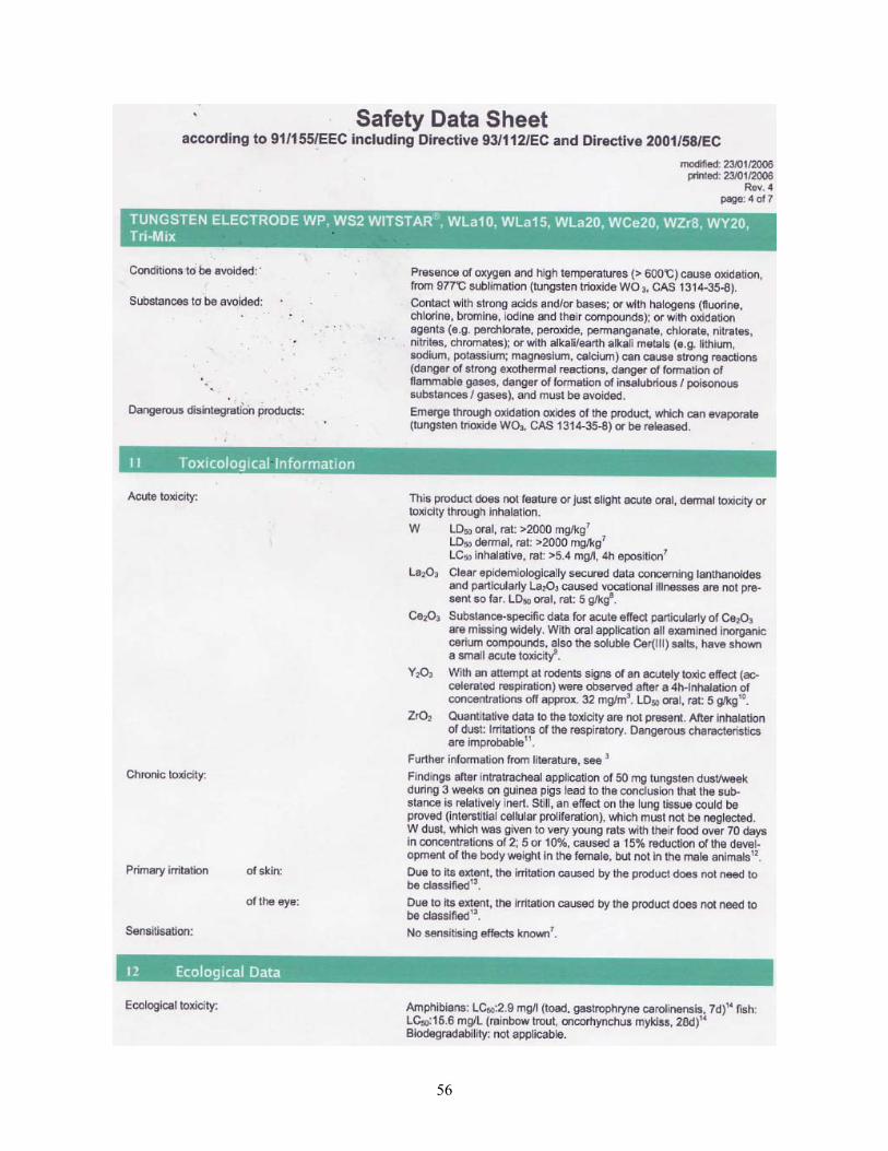
56

57
58

59
Appendix G
Plenum / Closure Weld Tests
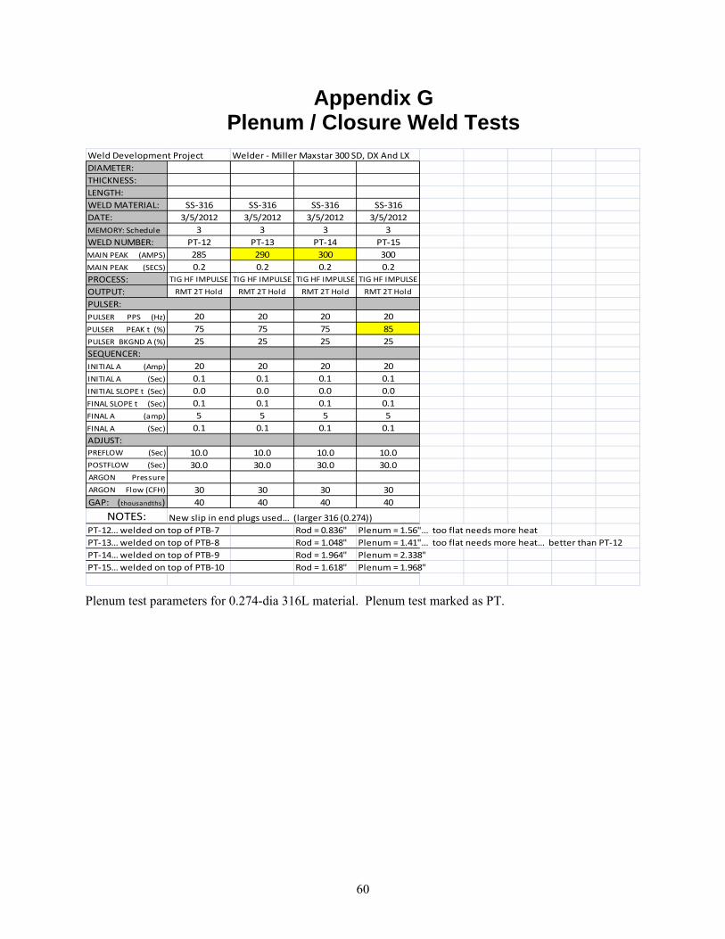
60
Appendix G Plenum / Closure Weld Tests
Weld Development Project Welder ‐ Miller Maxstar 300 SD, DX And LX
DIAMETER:
THICKNESS:
LENGTH:
WELD MATERIAL: SS‐316 SS‐316 SS‐316 SS‐316
DATE: 3/5/2012 3/5/2012 3/5/2012 3/5/2012
MEMORY: Schedule 3 3 3 3
WELD NUMBER: PT‐12 PT‐13 PT‐14 PT‐15
MAIN PEAK (AMPS) 285 290 300 300
MAIN PEAK (SECS) 0.2 0.2 0.2 0.2
PROCESS: TIG HF IMPULSE TIG HF IMPULSE TIG HF IMPULSE TIG HF IMPULSE
OUTPUT: RMT 2T Hold RMT 2T Hold RMT 2T Hold RMT 2T Hold
PULSER:
PULSER PPS (Hz) 20 20 20 20
PULSER PEAK t (%) 75 75 75 85
PULSER BKGND A (%) 25 25 25 25
SEQUENCER:
INITIAL A (Amp) 20 20 20 20
INITIAL A (Sec) 0.1 0.1 0.1 0.1
INITIAL SLOPE t (Sec) 0.0 0.0 0.0 0.0
FINAL SLOPE t (Sec) 0.1 0.1 0.1 0.1
FINAL A (amp) 5 5 5 5
FINAL A (Sec) 0.1 0.1 0.1 0.1
ADJUST:
PREFLOW (Sec) 10.0 10.0 10.0 10.0
POSTFLOW (Sec) 30.0 30.0 30.0 30.0
ARGON Pressure
ARGON Flow (CFH) 30 30 30 30
GAP: (thousandths) 40 40 40 40
NOTES: New slip in end plugs used… (larger 316 (0.274))
PT‐12… welded on top of PTB‐7 Rod = 0.836" Plenum = 1.56"… too flat needs more heat
PT‐13… welded on top of PTB‐8 Rod = 1.048" Plenum = 1.41"… too flat needs more heat… better than PT‐12
PT‐14… welded on top of PTB‐9 Rod = 1.964" Plenum = 2.338"
PT‐15… welded on top of PTB‐10 Rod = 1.618" Plenum = 1.968"
Plenum test parameters for 0.274-dia 316L material. Plenum test marked as PT.
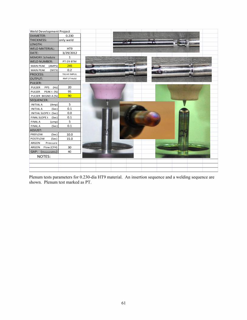
61
Weld Development Project
DIAMETER: 0.230
THICKNESS: only weld
LENGTH:
WELD MATERIAL: HT9
DATE: 3/29/2012
MEMORY: Schedule 1
WELD NUMBER: PT‐29 BTM
MAIN PEAK (AMPS) 245
MAIN PEAK (SECS) 0.2
PROCESS: TIG HF IMPUL
OUTPUT: RMT 2T Hold
PULSER:
PULSER PPS (Hz) 20
PULSER PEAK t (%) 95
PULSER BKGND A (%) 90
SEQUENCER:
INITIAL A (Amp) 5
INITIAL A (Sec) 0.1
INITIAL SLOPE t (Sec) 0.0
FINAL SLOPE t (Sec) 0.1
FINAL A (amp) 5
FINAL A (Sec) 0.1
ADJUST:
PREFLOW (Sec) 10.0
POSTFLOW (Sec) 15.0
ARGON Pressure
ARGON Flow (CFH) 30
GAP: (thousandths) 40
NOTES:
Plenum tests parameters for 0.230-dia HT9 material. An insertion sequence and a welding sequence are shown. Plenum test marked as PT.
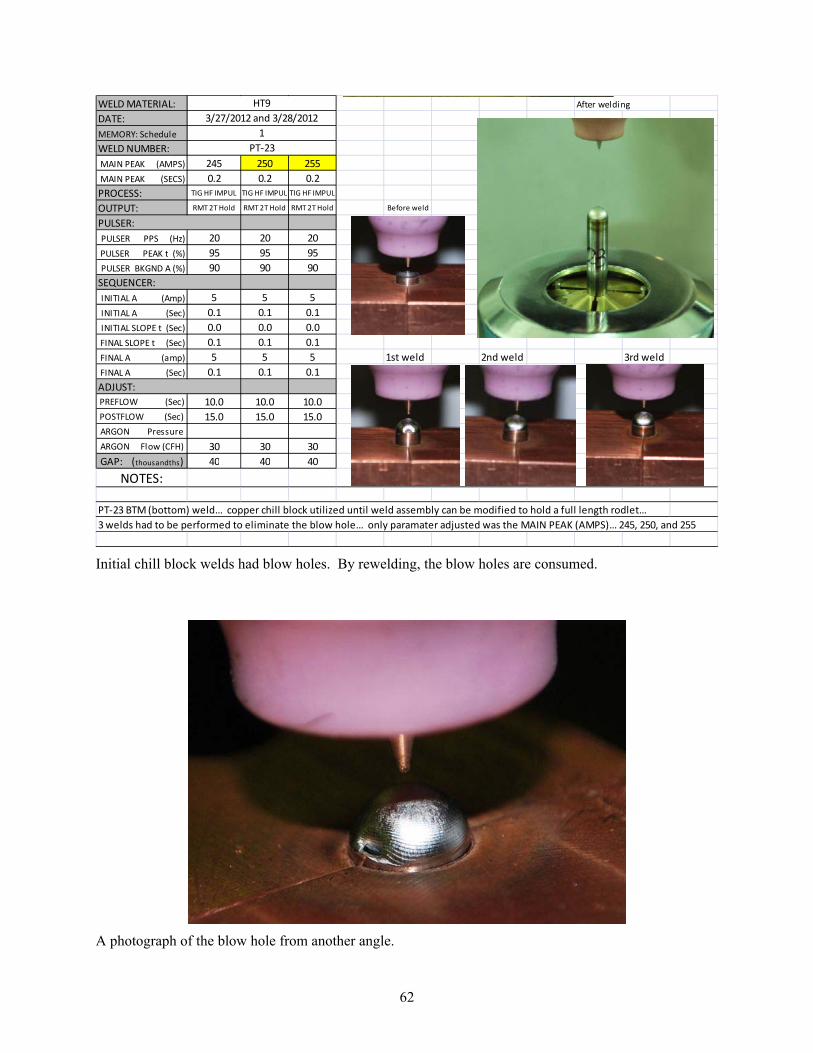
62
WELD MATERIAL: After welding
DATE:
MEMORY: Schedule
WELD NUMBER:
MAIN PEAK (AMPS) 245 250 255
MAIN PEAK (SECS) 0.2 0.2 0.2
PROCESS: TIG HF IMPUL TIG HF IMPUL TIG HF IMPUL
OUTPUT: RMT 2T Hold RMT 2T Hold RMT 2T Hold Before weld
PULSER:
PULSER PPS (Hz) 20 20 20
PULSER PEAK t (%) 95 95 95
PULSER BKGND A (%) 90 90 90
SEQUENCER:
INITIAL A (Amp) 5 5 5
INITIAL A (Sec) 0.1 0.1 0.1
INITIAL SLOPE t (Sec) 0.0 0.0 0.0
FINAL SLOPE t (Sec) 0.1 0.1 0.1
FINAL A (amp) 5 5 5 1st weld 2nd weld 3rd weld
FINAL A (Sec) 0.1 0.1 0.1
ADJUST:
PREFLOW (Sec) 10.0 10.0 10.0
POSTFLOW (Sec) 15.0 15.0 15.0
ARGON Pressure
ARGON Flow (CFH) 30 30 30
GAP: (thousandths) 40 40 40
NOTES:
PT‐23 BTM (bottom) weld… copper chill block utilized until weld assembly can be modified to hold a full length rodlet…
3 welds had to be performed to eliminate the blow hole… only paramater adjusted was the MAIN PEAK (AMPS)… 245, 250, and 255
HT9
3/27/2012 and 3/28/2012
1
PT‐23
Initial chill block welds had blow holes. By rewelding, the blow holes are consumed.
A photograph of the blow hole from another angle.

63
Weld Development Project Welder ‐ Miller Maxstar 300
LENGTH:
THICKNESS:
DIAMETER: 0.230 0.230 0.230
WELD MATERIAL: HT9 HT9 HT9 B7
DATE: 3/19/2012 3/19/2012 3/19/2012
MEMORY: Schedule 1 1 1
WELD NUMBER: B7 Top B8 Top B9 Top
MAIN PEAK (AMPS) 250 250 250
MAIN PEAK (SECS) 0.2 0.2 0.2
PROCESS: TIG HF IMPULSE TIG HF IMPULSE TIG HF IMPULSE
OUTPUT: RMT 2T Hold RMT 2T Hold RMT 2T Hold
PULSER:
PULSER PPS (Hz) 20 20 20
PULSER PEAK t (%) 95 95 95 B8
PULSER BKGND A (%) 90 90 90
SEQUENCER:
INITIAL A (Amp) 5 5 5
INITIAL A (Sec) 0.1 0.1 0.1
INITIAL SLOPE t (Sec) 0.0 0.0 0.0
FINAL SLOPE t (Sec) 0.1 0.1 0.1
FINAL A (amp) 5 5 5
FINAL A (Sec) 0.1 0.1 0.1
ADJUST: B9
PREFLOW (Sec) * 1.0 1.0 1.0
POSTFLOW (Sec) * 3.0 3.0 3.0
ARGON Pressure
ARGON Flow (CFH) 30 30 30
GAP: (thousandths) 40 40 60
NOTES: Rodlets B7, B8, & B9 were loaded with @ 8 grams of sodium and sealed welded with the above parameters
B7 ‐ Good weld
B8 ‐ Good weld
B9 ‐ Good weld
* Short argon flow durations were to allow a 2nd weld to be done quickly if blow holes… (no blow holes)
These welds were done with sodium and seal welded with the above parameters. No blow holes were apparent, and these values are the core for the final welding procedure parameters.
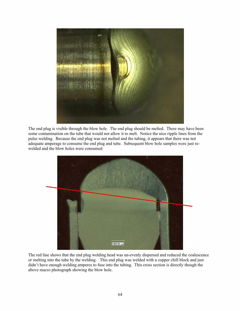
64
The end plug is visible through the blow hole. The end plug should be melted. There may have been some contamination on the tube that would not allow it to melt. Notice the nice ripple lines from the pulse welding. Because the end plug was not melted and the tubing, it appears that there was not adequate amperage to consume the end plug and tube. Subsequent blow hole samples were just re-welded and the blow holes were consumed
The red line shows that the end plug welding head was un-evenly dispersed and reduced the coalescence or melting into the tube by the welding. This end plug was welded with a copper chill block and just didn’t have enough welding amperes to fuse into the tubing. This cross section is directly though the above macro photograph showing the blow hole.
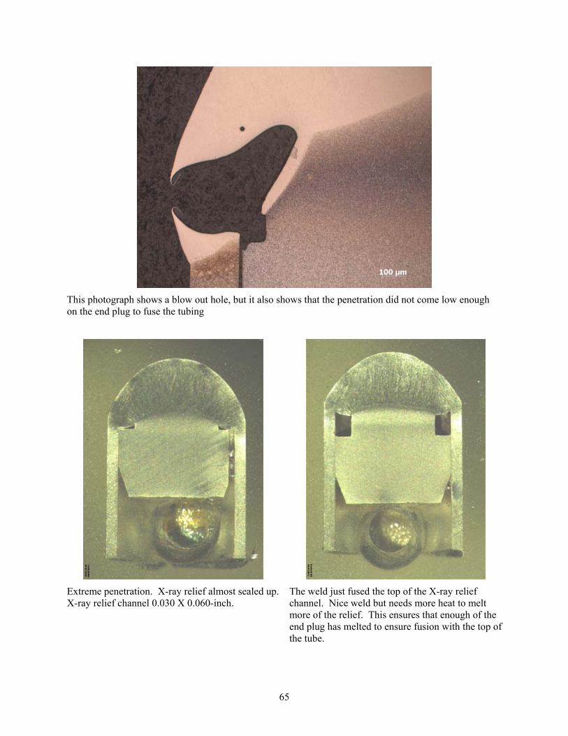
65
This photograph shows a blow out hole, but it also shows that the penetration did not come low enough on the end plug to fuse the tubing
Extreme penetration. X-ray relief almost sealed up. X-ray relief channel 0.030 X 0.060-inch.
The weld just fused the top of the X-ray relief channel. Nice weld but needs more heat to melt more of the relief. This ensures that enough of the end plug has melted to ensure fusion with the top of the tube.

66
Three tubes mounted in epoxy. Three variations of peak ampere shown by variations of the visible X-ray relief in the end plugs.
Two welds under welded showing lack of fusion into end of the tubing and the dome shapes are not very pronounced.
Tube ready to be welded in the collet fixture on the welding station.
Welding torch with tungsten electrode
Collet tightening lever
Tubing adjusting platen
XY positioning slides
Collet fixture
Z positioning slide

67
Appendix H
Helium Preliminary Study

68
Appendix H Helium Preliminary Study
Here are the two samples that were leak checked. Initially they were both put into a bell jar and sucked down, but the tester then realized that was not what was asked. Then the tubes were checked each separately. The PT-14 had 2 X 10⁻⁵ rate, but the PT-15, had no results because the helium had leaked out before the test could begin. More tests are needed to be done, but more are needed for determining the time required before welding and to verify the non-issue about the helium affecting the welding.

69
Appendix I
Set-up Data Acquisition System Arc Agent 3000P onto a Miller MaxStar 300

70
Appendix I Set-up Data Acquisition System Arc Agent 3000P
onto a Miller MaxStar 300
Miller MaxStar 300 (ampere) power supply TIG filter to remove RF noise for arc starting
Current sensor with 16 bit resolution 3000 Arc Agent monitoring system
3000 Arc Agent back side view View of monitor, PC, Arc Agent, welding system, and power supply

71
Appendix J
Data Acquisition Signature

72
Appendix J Data Acquisition Signature
DIAMETER: 0.230
THICKNESS:
LENGTH: 5.625
WELD MATERIAL: HT9
DATE: 4/18/2012
MEMORY: Schedule Part # 3
WELD NUMBER: PT‐33 BTM
MAIN PEAK (AMPS) 255
MAIN PEAK (SECS) 0.2
PROCESS: TIG HF IMPULSE
OUTPUT: RMT 2T Hold
PULSER:
PULSER PPS (Hz) 65
PULSER PEAK t (%) 95
PULSER BKGND A (%) 95
SEQUENCER:
INITIAL A (Amp) 5
INITIAL A (Sec) 0.1
INITIAL SLOPE t (Sec) 0.0
FINAL SLOPE t (Sec) 0.1
FINAL A (amp) 5
FINAL A (Sec) 0.1
ADJUST:
PREFLOW (Sec) 5.0
POSTFLOW (Sec) 10.0
ARGON Pressure
ARGON Flow (CFH) 30
GAP: (thousandths) 40
Volt 9.78
Amp 95.1
Watt 1478
Kj/in 2.217
The data acquisition software from Arc Agent adds another dimension to the development of welding procedures. Data added includes the values for the volts, amperes, watts and kilojoules per inch of each weld. See the bottom rows of the above table. Plus, a “signature” or a graphical trace of the amperes and voltages is captured for each weld. An example of this is shown in the graph below.

73
Appendix K
Resistance Welding

74
Appendix K Resistance Welding
The following photographs show an existing INL process, but the materials for this project were never used because the welding engineer retired before tests were conducted.
Recent tube to end plug weld with resistance welding
SEM photograph of bond line showing metallurgical bond from resistance welding
Resistance welding system
Resistance welding has been used for years making fuel elements, but typically on cold fuel. With some effort this could be attempted, but would require extensive tooling development for in-cell work.

75
Appendix L
Draft Design of Remote In-cell Welding System

76
Appendix L Draft Design of Remote In-cell Welding System
Shaft support
Mounting plate
Torch holder
Torch with tungsten electrode
X slide
Z slide spacer
Torch holder plate
Z slide
HT9 Jacket 6-inch long
Riser cylinder
Colet holder
Colet base Colet base
Colet holder
Riser cylinder
Threaded adjustment cylinder
Threaded adjustment cylinder
316 Jacket 8-inch long
Locating hole
Side View with Collet in Welding Position

77
Torch holder
Torch with tungsten electrode
X and Z Slides
Torch holder plate
HT9 Jacket 6-inch long
Riser cylinder
Colet holder
Colet base Colet base
Colet holder
Riser cylinder
Threaded adjustment
cylinder
Threaded adjustment
cylinder
316 Jacket 8-inch long
Front View with Collet Holders in the Loading Position
Locating hole

78