Remote Type Pressure Sensors/ New Pressure Sensor … · * URJ (VCR®fitting compliant), TSJ...
35
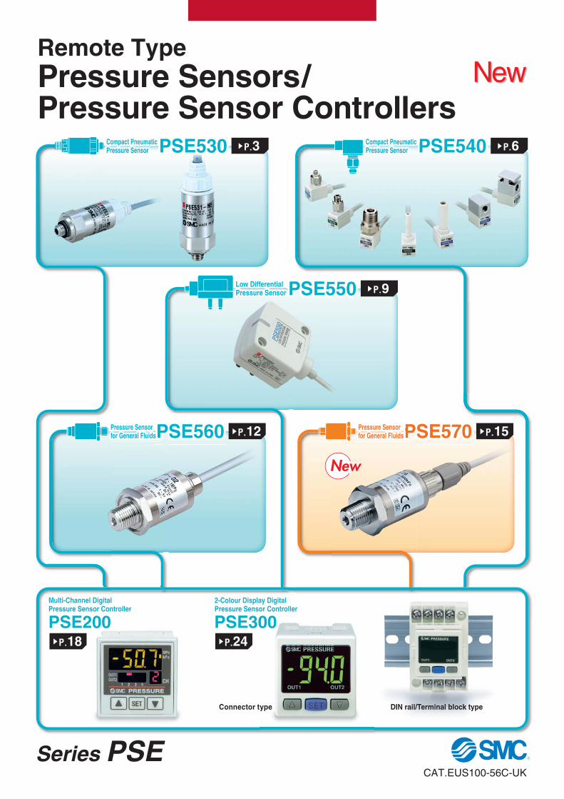
Multi-Channel Digital Pressure Sensor Controller PSE200 2-Colour Display Digital Pressure Sensor Controller PSE300 DIN rail/Terminal block type Connector type s P.18 s P.24 PSE530 Compact Pneumatic Pressure Sensor s P.3 PSE550 Low Differential Pressure Sensor s P.9 PSE540 Compact Pneumatic Pressure Sensor s P.6 PSE560 P P P P P P P P P P Pressure Sensor for General Fluids s P.12 s P.15 PSE570 P P P P P P P P P P P P P Pressure Sensor for General Fluids Remote Type Pressure Sensors/ Pressure Sensor Controllers New New CAT.EUS100-56C-UK Series PSE New New
Transcript of Remote Type Pressure Sensors/ New Pressure Sensor … · * URJ (VCR®fitting compliant), TSJ...
Multi-Channel DigitalPressure Sensor Controller
PSE2002-Colour Display DigitalPressure Sensor Controller
PSE300
DIN rail/Terminal block typeConnector type
sP.18 sP.24
PSE530Compact PneumaticPressure Sensor sP.3
PSE550Low DifferentialPressure Sensor sP.9
PSE540Compact PneumaticPressure Sensor sP.6
PSE560PPPPPPPPPPPPPPressure Sensor for General Fluids sP.12 sP.15PSE570PPPPPPPPPPPPPPPPressure Sensor
for General Fluids
Remote Type Pressure Sensors/Pressure Sensor Controllers
NewNew
CAT.EUS100-56C-UK
Series PSE
NewNew

Pressure Sensors Controllers
Model
PSE530
P.3
PSE540
P.6
PSE550
P.9
PSE560
P.12
PSE570
P.15
PSE200
P.18
PSE300
P.24
Bas
ic S
pec
ifica
tio
ns
Fluid Air General fluids
Rated pressure range(Minimum display)
Repeatability ±1 % (F.S.)
±0.2 % (F.S.)
±0.3 % (F.S.)
±0.2 % (F.S.)
±0.1 % (F.S.)
Voltage 12 to 24 V DC
No. of outputs for switch 5 outputs 2 outputs
Analogue output
1 to 5 V1 to 5 V
4 to 20 mA1 to 5 V
4 to 20 mA
Operating temp. 0 to 50 °C −10 to 60 °C 0 to 50 °C
Fu
nct
ion
s
Digital display 1-colour 2-colour
Enclosure IP40 IP65Front face IP65
Others IP40IP40
Wiring Connector Grommet Connector Connector
Major settingfunction
Keylock, Peak/Bottomvalues holding, Auto-preset,
Auto-shift, Display calibration,Anti-chattering
Oth
ers
Connection threads
Mreducer
MR, NPTreducer
Resin pipingR, NPT, RcURJ, TSJ* R
Int’l standards CE CE, UL, CSA CE CE CE, UL, CSA
Wir
ing e-con
Flexible cable
Mo
un
tin
g
Direct
With bracket
Panel mount
DIN rail
* URJ (VCR®fitting compliant), TSJ (Swagelok®fitting compliant)
Series PSE Variations
Pressure Sensors/Series PSE5
Pressure Sensor Controllers/Series PSE200/300
Main Functions (For details, refer to pages 31 to 33.)
Keylock Locks the keys from functioning.
Peak/Bottom values holding Displays the maximum and minimum values being set and can keep those values on the display.
Auto-preset Able to set the pressure automatically. In the case of suction verification, it memorises the pressure when adsorbed and released. By repeating several times, the optimum values are calculated automatically.
Auto-shift Stable switch output is available even though the supply pressure may fluctuate. Automatically corrects the set value in accordance with the fluctuations in the supply pressure.
Display calibration Able to adjust the displayed value (±5 %) and justify distribution of the values displayed on respective pressure switch.
Anti-chattering Prevents malfunction due to sharp pressure fluctuations. The detection of momentary pressure fluctuation as abnormal pressure can be prevented by changing the setting of the response time.
PSE200 PSE300
Applicable pressure sensor model Set/Display resolution
PSE531 PSE541 — PSE561 — 0.1 kPa 0.1 kPa
PSE533 PSE543 — PSE563 PSE573 0.1 kPa 0.2 kPa
PSE532 — — — — 0.1 kPa 0.1 kPa
— — — PSE564 PSE574 — 1 kPa
PSE530 PSE540 — PSE560 PSE570 0.001 MPa 0.001 MPa
— — PSE550 — — — 0.01 kPa
Input/Output specifications• NPN 5 outputs +
auto-shift input• PNP 5 outputs +
auto-shift input
Input/Output specifications
• NPN 2 outputs + 1–5 V outputs• NPN 2 outputs + 4–20 mA output• NPN 2 outputs +
auto-shift input• PNP 2 outputs + 1–5 V outputs• PNP 2 outputs + 4–20 mA output• PNP 2 outputs +
auto-shift input
Series PSESeries PSE Remote Type Pressure Sensors/Pressure Sensor ControllersRemote Type Pressure Sensors/Pressure Sensor Controllers
NewNew
PSE53 PSE54 PSE55 PSE56 PSE57
Rated pressure range−100 kPa
•0•
100 kPa•
500 kPa•
1 MPa•
Vacuum −101 kPa 0 PSE531 PSE541 — PSE561 —
Compoundpressure
−100 kPa 100 kPa PSE533 PSE543 — PSE563 PSE573
Positivepressure
0 100 kPa PSE532 — — — —
0 500 kPa — — — PSE564 PSE574
0 1 MPa PSE530 PSE540 — PSE560 PSE570Low differential
pressure 0 2 kPa — — PSE550 — —
NewNew
1 2

Unlocked
Locked
Sensor body
Connector cover
Compact PneumaticPressure Sensor
Series PSE530
Low pressure sensor (PSE532-�) is used to detect minute differentiations.Auto-shift function reduces infl uence of fl uctuations in the supply pressure.
Leak test of radiatorSeries PSE532 + PSE300
Application exampleApplication exampleConnector type
RoHS
Series Rated pressure range −100 kPa 0 100 kPa 500 kPa 1 MPa
PSE530 0 1 MPa
PSE531 –101 kPa 0
PSE532 0 101 kPa
PSE533 –101 kPa 101 kPa
33

For Pressure Switch Precautions and Specifi c Product Precautions, refer to “Handling Precautions for SMC Products” and the Operation Manual on SMC website.
How to Order
Option/Part No.When only optional parts are required, order using the part numbers listed below.
PSE53 0 M5OptionSensor range
Port size
Piping Specifications
Specifi cations
Note) The connector is not attached to the cable, but is included with the shipment.
Series PSE530Pressure Sensor
RoHS
Description Part no. Note
Connector for pressure sensor controller ZS-28-C 1 pc. per set
Sensor cable ZS-26-F Cable length: 3 m
Connector for pressure sensor controller + Sensor cable
ZS-26-J
Cable length: 3 mThe connector is not attachedto the cable at the time ofshipment.
Model PSE530 [Positive pressure] PSE531 [Vacuum] PSE532 [Low pressure] PSE533 [Compound pressure]
Rated pressure range 0 to 1 MPa 0 to –101 kPa 0 to 101 kPa –101 to 101 kPa
Extension analogue output range –0.1 to 0 MPa 10.1 to 0 kPa –10.1 to 0 kPa —
Proof pressure 1.5 MPa 500 kPa
Applicable fluid Air/Non-corrosive gas/Non-flammable gas
Power supply voltage 12 to 24 V DC ±10 %, Ripple (p-p) 10 % or less (with reverse connection protection)
Current consumption 15 mA or less (with no load)
Output specifications Analogue output 1 to 5 V (within rated pressure range), 0.6 to 1 V (within extension analogue output range), Output impedance: Approx. 1 kΩAccuracy (Ambient temperature at 25 °C) ±2 % F.S. (within rated pressure range), ±5 % F.S. (within extension analogue output range)
Linearity ±1 % F.S.
Repeatability ±1 % F.S.
Power supply voltage effect ±1 % F.S. based on the analogue output at 18 V ranging from 12 to 24 V DC
Env
iron
men
t Enclosure IP40
Temperature range Operating: 0 to 50 °C; Stored: –10 to 70 °C (No freezing or condensation)
Withstand voltage 1000 V AC (in 50 / 60 Hz) for 1 minute between terminals and housing
Insulation resistance 5 MΩ or more (500 V DC measured via megohmmeter) between terminals and housing
Temperature characteristics ±2 % F.S. (25 °C reference)
Sensor cable/Option Halogen-free heavy-duty cable, 3 cores, Ø 2.7, 3 m, Conductor area: 0.15 mm2, Insulator O.D.: 0.8 mm
Standards CE, RoHS
Model M5 R06 R07Port size M5 x 0.8 male thread Ø 6 reducer type 1/4 inch reducer type
Materials of parts in contact with fluid
Pressure sensor: Silicon, O-ring: NBR
Body: Stainless steel 304 Body: PBT
WeightWith sensor cable (3 m) 41 g 38 g
Without sensor cable 7 g 3.8 g
— None
L
Sensor cable (3 m)
C2L
Connector for pressure sensor controller (1 pc.) + Sensor cable (3 m)
M5 M5 x 0.8
R06 Ø 6 reducerR07 1/4 inch reducer
0 Positive pressure [0 to 1 MPa]
1 Vacuum [0 to –101 kPa]2 Low pressure [0 to 101 kPa]3 Compound pressure [–101 to 101 kPa]
4
PS
E53
0P
SE
540
PS
E55
0P
SE
560
PS
E57
0P
SE
200
PS
E30
0Con
trol
ler

1
Pressure
Ana
logu
e ou
tput
[V]
5
AC
0.6
B
5 5.5
4
3
3.429.427.2
12
5.4
M5 x 0.8
Pressure port
Ø 2
.5
Ø 13
Ø 1
2
Ø 7
.2
Pressure port3.4
5.4
Ø 7
.2Ø
12
Ø D
45.543.3
Ø 2
.7Ø
10.
4
9.8
1 kΩ +−
Brown DC (+)
Black OUT(Analogue output)
Blue DC (−)
12to
24 V DC
Mai
n ci
rcui
t
Load
Dimensions
PSE53�-M5
Analogue OutputInternal Circuit and Wiring Example
With sensor cable
PSE53�-
1 to 5 V DC
R06R07
[mm]
Model Applicable fi tting size (D)
PSE53�-R06 6
PSE53�-R07 1/4"
Range Rated pressure range A B CFor vacuum 0 to −101 kPa 0 −101 kPa 10.1 kPa
For compound pressure −101 kPa to 101 kPa −101 kPa 101 kPa —
For low pressure 0 to 101 kPa 0 101 kPa −10.1 kPa
For positive pressure 0 to 1 MPa 0 1 MPa −0.1 MPa
PSE53�Voltage output type1 to 5 VOutput impedanceApprox. 1 kΩ
5
Series PSE530
189.6
20.8
®
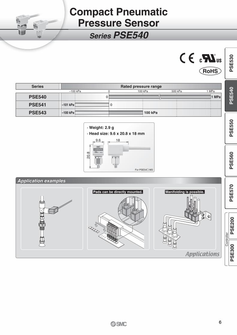
Series PSE540
Compact PneumaticPressure Sensor
Series Rated pressure range –100 kPa 0 100 kPa 500 kPa 1 MPa
PSE540 0 1 MPa
PSE541 –101 kPa 0
PSE543 –100 kPa 100 kPa
Application examplesApplication examples
Pads can be directly mounted. Manifolding is possible.
· Weight: 2.9 g
· Head size: 9.6 x 20.8 x 18 mm
For PSE54�-M3
RoHS
66
PS
E53
0P
SE
540
PS
E55
0P
SE
560
PS
E57
0P
SE
200
PS
E30
0Con
trol
ler

How to Order
Option/Part No.
PSE54 1 M3
Note) The connector is not attached to the cable, but is included with the shipment.
Port size
Sensor range
Specifi cations
Piping Specifications
Option (Connector)
Accuracy
Series PSE540Compact PneumaticPressure Sensor ®
RoHS
Model M3 M5 01 N01 R04 R06 IM5 IM5H
Port size M3 x 0.5 M5 x 0.8R 1/8
M5 x 0.8
NPT 1/8
M5 x 0.8Ø 4 reducer Ø 6 reducer
M5 femalethread,
through type
M5 femalethread,
through type(with mounting hole)
Material Case
Resin case: PBTFitting: Stainless steel 303
Resin case: PBTFitting: C3604BD
PBTResin case: PBT
Fitting: A6063S-T5
Pressure sensing section Pressure sensor: Silicon, O-ring: NBR
WeightWith sensor cable 42.4 g 42.7 g 49.3 g 41.4 g 41.6 g 43.3 g 44.1 g
Without sensor cable 2.9 g 3.2 g 9.8 g 1.9 g 2.1 g 3.8 g 4.6 g
0 Positive pressure [0 to 1 MPa]
1 Negative pressure [0 to –101 kPa]3 Compound pressure [–100 to 100 kPa]
Model PSE540 PSE541 PSE543Rated pressure range 0 to 1 MPa 0 to –101 kPa –100 to 100 kPa
Extension analogue output range –0.1 to 0 MPa 10.1 to 0 kPa —
Proof pressure 1.5 MPa 500 kPa
Applicable fluid Air/Non-corrosive gas/Non-flammable gas
Power supply voltage 12 to 24 V DC ±10 %, Ripple (p-p) 10 % or less (with reverse connection protection)
Current consumption 15 mA or less
Output specifications Analogue output 1 to 5 V (within rated pressure range), 0.6 to 1 V (within extension analogue output range), Output impedance: Approx. 1 kΩ
Accuracy (Ambient temperatureat 25 °C)
PSE54�: ±2 % F.S. (within rated pressure range), ±5 % F.S. (within extension analogue output range)PSE54�A: ±1 % F.S. (within rated pressure range), ±3 % F.S. (within extension analogue output range)
Linearity ±0.7 % F.S. or less ±0.4 % F.S.
Repeatability ±0.2 % F.S.
Power supply voltage effect ±0.8 % F.S.
En
viro
nm
ent Enclosure IP40
Operating temperature range Operating: 0 to 50 °C, Stored: –20 to 70 °C (No freezing or condensation)
Operating humidity range Operating/Stored: 35 to 85 % RH (No condensation)
Withstand voltage 1000 V AC (in 50 / 60 Hz) for 1 minute between terminals and housing
Insulation resistance 50 MΩ or more (500 V DC measured via megohmmeter) between terminals and housing
Temperature characteristics ±2 % F.S. (25 °C reference)
Sensor cable Oilproof heavy-duty vinyl cable (ellipse), 3 cores, 2.7 x 3.2, 3 m, Conductor area: 0.15 mm2, Insulator O.D.: 0.9 mm
Standards CE, UL/CSA (E216656), RoHS
— ±2 % F.S.A ±1 % F.S. — None
C2
Connector for pressuresensor controller (1 pc.)
M3 M3 x 0.5
M5 M5 x 0.8
01 R 1/8 (with M5 female thread)
N01 NPT 1/8 (with M5 female thread)
R04 Ø 4 reducer
R06 Ø 6 reducer
IM5M5 female thread,through type
IM5HM5 female thread,through type(with mounting hole)
Description Part no. Note
Connector for pressure sensor controller ZS-28-C 1 pc.
For Pressure Switch Precautions and Specifi c Product Precautions, refer to “Handling Precautions for SMC Products” and the Operation Manual on SMC website.
7

10.6
Pressure
Ana
logu
e ou
tput
[V]
5
AC B
With acrossflats 7
M3: M3 x 0.5M5: M5 x 0.8
10A B
B10
A
9.6
18 300013
4
M5 x 0.8
8.7
9
With acrossflats 12
14.4
10
M5 x 0.8
01: R 1/8N01: NPT 1/8
8
M5 x 0.8 7
8.7
13 3 Ø 3.4
1 kΩM
ain
circ
uit
+–
Brown DC (+)
Black OUT(Analogue output)
Blue DC (–)
12 to
24 V DC
Load
Dimensions
Common Dimensions
PSE54�- 01N01
PSE54�- M3M5 PSE54�- R04
R06
PSE54�-IM5
PSE54�-IM5H
Analogue Output
1 to 5 V DC
[mm] [mm]
Range Rated pressure range A B CFor vacuum 0 to –101 kPa 0 –101 kPa 10.1 kPa
For compound pressure –100 kPa to 100 kPa –100 kPa 100 kPa —
For positive pressure 0 to 1 MPa 0 1 MPa –0.1 MPa
PSE54�-R04 PSE54�-R06
A Ø 4 Ø 6
B 18 20
PSE54�-M3 PSE54�-M5
A 10.8 11.5
B 3 3.5
Internal Circuit and Wiring Example
PSE54�Voltage output type1 to 5 VOutput impedanceApprox. 1 kΩ
8
Compact Pneumatic Pressure Sensor Series PSE540
PS
E53
0P
SE
540
PS
E55
0P
SE
560
PS
E57
0P
SE
200
PS
E30
0Con
trol
ler

LED display
®
Series PSE550
Application examplesApplication examples
Can control air fl ow by monitoring the fl ow rate inside the duct.
Can control fi ltration and replacement periods by monitoring the clogging of the fi lter.
Can detect the liquid level through changes in the purge pressure.
Series PSE550 Series PSE550Series PSE550
Mounting directly Mounting withbracket
Power LED status indicator 2 mounting typesAccuracy
Proof pressure
65 kPa65 kPa
RoHSSeries Rated pressure range 0 1 kPa 2 kPa
PSE550 0 2 kPa
Low DifferentialPressure Sensor
Flow control Filter clogging monitoring Liquid level detection
±1 % F.S.±1 % F.S.
99
For Pressure Switch Precautions and Specifi c Product Precautions, refer to “Handling Precautions for SMC Products” and the Operation Manual on SMC website.
10
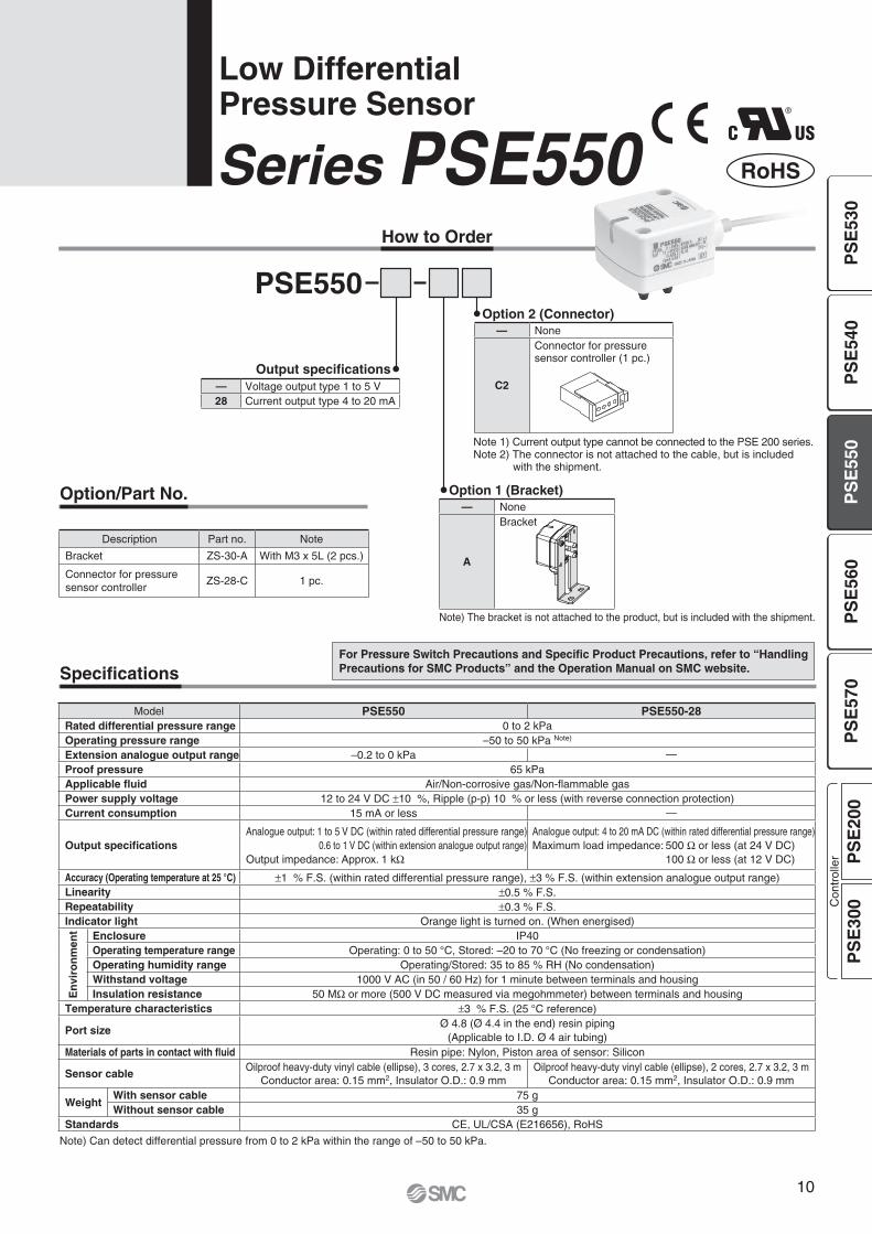
How to Order
Option/Part No.
PSE550
Note) The bracket is not attached to the product, but is included with the shipment.
Option 2 (Connector)
Note 1) Current output type cannot be connected to the PSE 200 series.Note 2) The connector is not attached to the cable, but is included
with the shipment.
Output specifications
Option 1 (Bracket)
Series PSE550Low DifferentialPressure Sensor
Specifications
Note) Can detect differential pressure from 0 to 2 kPa within the range of –50 to 50 kPa.
®
RoHS
Model PSE550 PSE550-28Rated differential pressure range 0 to 2 kPaOperating pressure range –50 to 50 kPa Note)
Extension analogue output range –0.2 to 0 kPa —Proof pressure 65 kPaApplicable fluid Air/Non-corrosive gas/Non-flammable gasPower supply voltage 12 to 24 V DC ±10 %, Ripple (p-p) 10 % or less (with reverse connection protection)Current consumption 15 mA or less —
Output specificationsAnalogue output: 1 to 5 V DC (within rated differential pressure range)
0.6 to 1 V DC (within extension analogue output range)Output impedance: Approx. 1 kΩ
Analogue output: 4 to 20 mA DC (within rated differential pressure range)Maximum load impedance: 500 Ω or less (at 24 V DC) 100 Ω or less (at 12 V DC)
Accuracy (Operating temperature at 25 °C) ±1 % F.S. (within rated differential pressure range), ±3 % F.S. (within extension analogue output range)Linearity ±0.5 % F.S.Repeatability ±0.3 % F.S.Indicator light Orange light is turned on. (When energised)
En
viro
nm
ent Enclosure IP40
Operating temperature range Operating: 0 to 50 °C, Stored: –20 to 70 °C (No freezing or condensation)Operating humidity range Operating/Stored: 35 to 85 % RH (No condensation)Withstand voltage 1000 V AC (in 50 / 60 Hz) for 1 minute between terminals and housingInsulation resistance 50 MΩ or more (500 V DC measured via megohmmeter) between terminals and housing
Temperature characteristics ±3 % F.S. (25 °C reference)
Port sizeØ 4.8 (Ø 4.4 in the end) resin piping
(Applicable to I.D. Ø 4 air tubing)Materials of parts in contact with fluid Resin pipe: Nylon, Piston area of sensor: Silicon
Sensor cableOilproof heavy-duty vinyl cable (ellipse), 3 cores, 2.7 x 3.2, 3 m
Conductor area: 0.15 mm2, Insulator O.D.: 0.9 mmOilproof heavy-duty vinyl cable (ellipse), 2 cores, 2.7 x 3.2, 3 m
Conductor area: 0.15 mm2, Insulator O.D.: 0.9 mm
WeightWith sensor cable 75 gWithout sensor cable 35 g
Standards CE, UL/CSA (E216656), RoHS
Description Part no. Note
Bracket ZS-30-A With M3 x 5L (2 pcs.)
Connector for pressuresensor controller
ZS-28-C 1 pc.
— None
A
Bracket
— None
C2
Connector for pressure sensor controller (1 pc.)
— Voltage output type 1 to 5 V28 Current output type 4 to 20 mA
PS
E53
0P
SE
540
PS
E55
0P
SE
560
PS
E57
0P
SE
200
PS
E30
0Con
trol
ler

12 to
24 V DC
1 kΩM
ain
circ
uit
+–
Brown DC (+)
Black OUT(Analogue output)
Blue DC (–) Load
12 to
24 V DC
+–
Load
LoadMai
n ci
rcui
t
Brown LINE (+)
Blue LINE (–)
1
0.6
5
0−0.2 2 Differentialpressure [kPa]
Ana
logu
e ou
tput
[V]
4
20
0 2 Differentialpressure [kPa]
Ana
logu
e ou
tput
[mA
]
27
10.7
7.3
25
24.3
11.7 10.4
Ø 4
.8Ø
4.4
37
37
930
00
Ø 15
2 x M3 x 0.5 depth 4
2 x Ø 3.5 throughIndicator light
40.9
11.6 4.
2
7
20
69.5
37
27
1.6
68
2538
.5
A
BracketA View
Analogue Output
Internal Circuit and Wiring Example
Dimensions
PSE550Voltage output type1 to 5 VOutput impedanceApprox. 1 kΩ
PSE550-28Current output type4 to 20 mAAllowable load impedance500 Ω or less (at 24 V DC)100 Ω or less (at 12 V DC)
∗ Install the load either on the LINE (+) or LINE (–) side.
With bracket
1 to 5 V DC 4 to 20 mA DC
11
Series PSE550
®
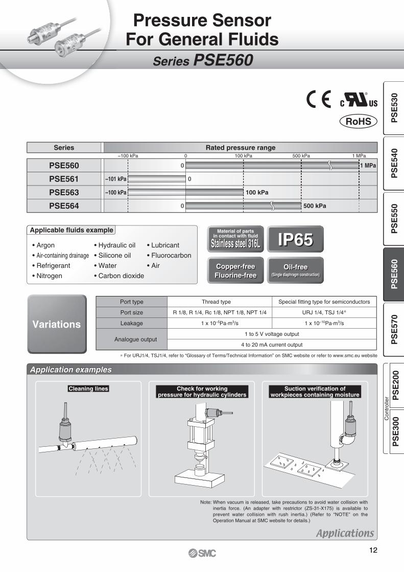
Series PSE560
Pressure SensorFor General Fluids
• Argon
• Air-containing drainage
• Refrigerant
• Nitrogen
• Hydraulic oil
• Silicone oil
• Water
• Carbon dioxide
• Lubricant
• Fluorocarbon
• Air
Applicable fl uids example Material of partsin contact with fl uid IP65IP65Copper-freeFluorine-freeCopper-freeFluorine-free
Oil-free(Single diaphragm construction)
Oil-free(Single diaphragm construction)
Variations
Application examplesApplication examples
Cleaning lines Check for workingpressure for hydraulic cylinders
Suction verifi cation ofworkpieces containing moisture
Note: When vacuum is released, take precautions to avoid water collision with inertia force. (An adapter with restrictor (ZS-31-X175) is available to prevent water collision with rush inertia.) (Refer to “NOTE” on the Operation Manual at SMC website for details.)
∗ For URJ1/4, TSJ1/4, refer to “Glossary of Terms/Technical Information” on SMC website or refer to www.smc.eu website
RoHS
Port type Thread type Special fi tting type for semiconductors
Port size R 1/8, R 1/4, Rc 1/8, NPT 1/8, NPT 1/4 URJ 1/4, TSJ 1/4∗
Leakage 1 x 10⁻⁵Pa·m3/s 1 x 10⁻¹⁰Pa·m3/s
Analogue output1 to 5 V voltage output
4 to 20 mA current output
Series Rated pressure range −100 kPa 0 100 kPa 500 kPa 1 MPa
PSE560 0 1 MPa
PSE561 –101 kPa 0
PSE563 –100 kPa 100 kPa
PSE564 0 500 kPa
Stainless steel 316LStainless steel 316L
1212
PS
E53
0P
SE
540
PS
E55
0P
SE
560
PS
E57
0P
SE
200
PS
E30
0Con
trol
ler

®
RoHS
How to Order
PSE56 0 01Port size
Option (Connector)Sensor range
Output specifications
Specifications
Piping Specifications
Option/Part No.
Note 1) Current output type cannot be connected to the PSE200 series.
Note 2) The connector is not attached to the cable, but is included with the shipment.
Series PSE560Pressure Sensor For General Fluids
Model 01 02 N01 N02 C01 A2 B2
Port sizeR 1/8
M5 x 0.8
R 1/4
M5 x 0.8
NPT 1/8
M5 x 0.8
NPT 1/4
M5 x 0.8Rc 1/8 URJ 1/4 TSJ 1/4
Material Case: C3604 + Nickel plating, Piping port/Pressure sensor: Stainless steel 316L
WeightWith sensor cable 193 g 200 g 194 g 201 g 187 g 203 g 193 g
Without sensor cable 101 g 108 g 102 g 109 g 95 g 111 g 101 g
Model PSE56�-� PSE56�-�-28Applicable fluid Liquid or gas that will not corrode or attack stainless steel 316L
Power supply voltage 12 to 24 V DC ±10 %, Ripple (p-p) 10 % or less (with reverse connection protection)
Current consumption 10 mA or less —
Output specificationsAnalogue output: 1 to 5 V (within rated pressure range)
0.6 to 1 V (within extension analogue output range)Output impedance: Approx. 1 kΩ
Analogue output: 4 to 20 mA DC (within rated pressure range)Maximum load impedance: 500 Ω or less (at 24 V DC) 100 Ω or less (at 12 V DC)
Accuracy (Ambient temperature at 25 °C) ±1 % F.S. (within rated pressure range), ±3 % F.S. (within extension analogue output range)
Linearity ±0.5 % F.S.
Repeatability ±0.2 % F.S.
Power supply voltage effect ±0.3 % F.S.
En
viro
nm
ent Enclosure IP65
Operating temperature range Operating: –10 to 60 °C, Stored: –20 to 70 °C (No freezing or condensation)
Operating humidity range Operating/Stored: 35 to 85 % RH (No condensation)
Withstand voltage 250 V AC for 1 minute between terminals and housing
Insulation resistance 50 MΩ or more (50 V DC measured via megohmmeter) between terminals and housing
Temperature characteristics ±2 % F.S. (0 to 50 °C: 25 °C reference), ±3 % F.S. (–10 to 60 °C: 25 °C reference)
Sensor cablePSE56�-�: Oilproof heavy-duty vinyl cable with air tubing, 3 cores, Ø 5.1, 3 m, Conductor area: 0.2 mm2, Insulator O.D.: 1.12 mm
PSE56�-�-28: Oilproof heavy-duty vinyl cable with air tubing, 2 cores, Ø 5.1, 3 m, Conductor area: 0.2 mm2, Insulator O.D.: 1.12 mm
Standards CE, UL/CSA (E216656), RoHS
Description Part no. Note
Connector for pressure sensor controller ZS-28-C 1 pc.
Adapter with restrictor Rc 1/4 ZS-31-X175 1 pc.
Adapter with restrictor NPT 1/4 ZS-31-X186 1 pc.
Adapter with restrictor Rc 1/8 ZS-31-X188 1 pc.
Adapter with restrictor NPT 1/8 ZS-31-X189 1 pc.
Model PSE560 (Positive pressure) PSE561 (Vacuum) PSE563 (Compound pressure) PSE564 (Positive pressure)
Rated pressure range 0 to 1 MPa 0 to –101 kPa –100 to 100 kPa 0 to 500 kPa
Extension analogue output range –0.1 to 0 MPa 10.1 to 0 kPa — –50 to 0 kPa
Proof pressure 1.5 MPa 500 kPa 500 kPa 750 kPa
— Voltage output type 1 to 5 V28 Current output type 4 to 20 mA
— None
C2
Connector for pressuresensor controller (1 pc.)
01 R 1/8 (with M5 female thread)02 R 1/4 (with M5 female thread)
C01 Rc 1/8N01 NPT 1/8 (with M5 female thread)N02 NPT 1/4 (with M5 female thread)A2 URJ 1/4B2 TSJ 1/4
0 Positive pressure [0 to 1 MPa]
1 Vacuum [0 to –101 kPa]3 Compound pressure [–100 to 100 kPa]4 Positive pressure [0 to 500 kPa]
For Pressure Switch Precautions and Specifi c Product Precautions, refer to “Handling Precautions for SMC Products” and the Operation Manual on SMC website.
13

10.6
Pressure
Ana
logu
e ou
tput
[V]
5
AC B
4
Pressure
Ana
logu
e ou
tput
[mA
]
20
A B
M5 x 0.8
24
B5.5
Ø 2
4
Ø 1
4
205
30
Ø 5
.1
A
Air tubing(Atmospheric release)
Part-C
11.5 302537.5
B24
24AB
24B
A
Ø 1
I
H D
E
G
F
M5 x 0.8
1 kΩM
ain
circ
uit
+–
Brown DC (+)
Black OUT(Analogue output)
Blue DC (–)
12 to
24 V DC
Load
Mai
n ci
rcui
t
+–
Brown LINE (+)
Blue LINE (–)
12 to
24 V DC
Load
Load
Analogue Output
Dimensions
PSE56�-C01 PSE56�-A2
PSE56�-B2
Adapter with restrictorZS-31-X���
∗ The dimensions of part C are common to all PSE56� models.
1 to 5 V DC 4 to 20 mA DC
PSE56�- , PSE56�-0102
N01N02
[mm]
[mm]
Be sure to release the air in the air tubing of the cable to the atmosphere. If the air tubing is restricted, or left in environments where it is exposed to water or oil, it cannot be detected normally.
Note) If it is predicted that the pressure, such as the water hammer or surge pressure fl uctuates rapidly, refer to the Precautions stated in the Operation Manual at SMC website (http://www.smcworld.com).
Part no. D E F G H IZS-31-X188 20 9 R 1/8 Rc 1/8 14 1.5
ZS-31-X189 20 9 NPT 1/8 NPT 1/8 14 1.5
ZS-31-X175 29 13 R 1/4 Rc 1/4 17 1.6
ZS-31-X186 29 13 NPT 1/4 NPT 1/4 17 1.6
Model A BPSE56�-01 8.2 R 1/8
PSE56�-02 12 R 1/4
PSE56�-N01 9.2 NPT 1/8
PSE56�-N02 12.2 NPT 1/4
PSE56�-C01 — Rc 1/8
PSE56�-A2 15.5 URJ 1/4
PSE56�-B2 9.5 TSJ 1/4
Range Rated pressure range A B CFor vacuum 0 to –101 kPa 0 –101 kPa 10.1 kPa
For compound pressure –100 kPa to 100 kPa –100 kPa 100 kPa —
For positivepressure
0 to 1 MPa 0 1 MPa –0.1 MPa
0 to 500 kPa 0 500 kPa –50 kPa
Internal Circuit and Wiring Example
PSE56�-�Voltage output type1 to 5 VOutput impedanceApprox. 1 kΩ
PSE56�-�-28Current output type4 to 20 mAAllowable load impedance500 Ω or less (at 24 V DC)100 Ω or less (at 12 V DC)
∗ Install the load either on the LINE (+) or LINE (–) side.
14
Pressure Sensor for General Fluids Series PSE560
PS
E53
0P
SE
540
PS
E55
0P
SE
560
PS
E57
0P
SE
200
PS
E30
0Con
trol
ler

Series PSE570
Pressure SensorFor General Fluids
Adopted M12 connector.
Application examplesApplication examples
Liquid coolant pressurecontrol
Discharge pressure control forcompressor
Series Rated pressure range −100 kPa 0 100 kPa 500 kPa 1 MPa
PSE570 0 1 MPa
PSE573 −100 kPa 100 kPa
PSE574 0 500 kPa
RoHS
� Materials of parts in contact with fl uid
Piping port∗ C3604 + Nickel plating
Pressure sensor∗ Al2O3 (Alumina 96 %)
O-ring FKM + Grease
∗ Stainless steel 316L is used for the PSE560.For details, refer to page 12.
3.0 MPa∗
500 V AC
<Twice as compared with the PSE560> ∗ For PSE570
<Twice as compared with the PSE560>
Proof pressure
IP65
Withstand voltage
Suction verifi cation ofworkpieces containing moisture
Note: When vacuum is released, take precautions to avoid water collision with inertia force. (An adapter with restrictor (ZS-31-X175) is available to prevent water collision with rush inertia.) (Refer to “NOTE” on the Operation Manual at SMC website for details.)
1515

Series PSE570Pressure SensorFor General Fluids
How to Order
PSE57 0 01
Specifi cations
Option/Part No.
Description Part no. Note
Lead wire and M12 connector (3 m), Straight ZS-37-A 1 pc.
Connector for pressure sensor controller ZS-28-CA-4 1 pc.
Adapter with restrictor Rc 1/4 ZS-31-X175 1 pc.
Adapter with restrictor Rc 1/8 ZS-31-X188 1 pc.
Model PSE570 PSE573 PSE574
Pressure specifications
Rated pressure range 0 to 1 MPa −100 to 100 kPa 0 to 500 kPa
Proof pressure 3.0 MPa 600 kPa 1.5 MPa
Temperature characteristics ±2 % F.S. (0 to 50 °C)±3 % F.S. (–10 to 60 °C)
±3 % F.S. (0 to 50 °C)±4 % F.S. (–10 to 60 °C)
For Pressure Switch Precautions and Specifi c Product Precautions, refer to “Handling Precautions for SMC Products” and the Operation Manual on SMC website.
Model PSE57�-� PSE57�-�-28Fluid Applicable fl uid Gas or liquid that will not attack or corrode materials of parts in contact with fl uid
Electrical specifi cations
Power supply voltage 12 to 24 V DC ±10 % with 10 % voltage ripple or less
Current consumption 10 mA or less
Protection Reverse connection protection
Analogue output
OutputAnalogue output: 1 to 5 V
Output impedance: Approx. 1 kΩ
Analogue output: 4 to 20 mAMaximum load impedance: 500 Ω or less (at 24 V DC)
100 Ω or less (at 12 V DC)
Analogue output accuracy(Ambient temperature at 25 °C) ±1.0 % F.S.
Linearity ±0.5 % F.S.
Repeatability ±0.2 % F.S. (Ambient temperature at 25 °C)
Environment
Enclosure IP65
Withstand voltage 500 V AC for 1 minute between terminals and housing
Insulation resistance 100 MΩ or more (500 V DC measured via megohmmeter) between terminals and housing
Operating temperature range Operating: –10 to 60 °C, Stored: –20 to 70 °C (No freezing or condensation)
Operating humidity range Operating/Stored: 35 to 85 % RH (No condensation)
Standards CE, RoHS
Piping Specifi cationsModel 01 02
Port sizeR 1/8
M5 x 0.8R 1/4
M5 x 0.8
Materials of parts in contact with fl uid
Piping port: C3604 + Nickel platingPressure sensor: Al2O3 (Alumina 96 %)
O-ring: FKM + Grease
WeightWithout cable 88 g 95 g
With cable 175 g 182 g
Cable Specifi cations
ConductorNominal cross section AWG23
Outside diameter 0.72 mm
Insulator
Material Cross-linked vinyl
Outside diameter 1.14 mm
Colour Brown, Blue, Black, White
Sheath Material Oil resistant vinyl
Finished outside diameter Ø 4
Length 3 m
RoHS
Output specifications— Voltage output type 1 to 5 V28 Current output type 4 to 20 mA
Lead wire— Lead wire and M12 connector (3 m), StraightN None
Port size01 R 1/8 (with M5 female thread)02 R 1/4 (with M5 female thread)
Sensor range0 Positive pressure [0 to 1 MPa]3 Compound pressure [–100 to 100 kPa]4 Positive pressure [0 to 500 kPa]
16
PS
E53
0P
SE
540
PS
E55
0P
SE
560
PS
E57
0P
SE
200
PS
E30
0Con
trol
ler
RoHS
PS
E53
0

N.C.
Black OUT(Voltage output)
+–
12 to
24 V DC1 kΩ
Mai
n ci
rcui
t
Brown DC (+)
Blue DC (–) Load
N.C.+–
12 to
24 V DC
Mai
n ci
rcui
t
Brown DC (+)
Blue DC (–) Load
Black OUT(Current output)
1
Pressure
Ana
logu
e ou
tput
[V] 5
A B
4
Pressure
Ana
logu
e ou
tput
[mA
] 20
A B
10.5
M12
23.8
36.5A
B
24
M5 x 0.8 depth 4
30
45
3000(38.6)
Ø 1
5
2: White1: Brown
M12
3: Blue4: Black
ED
G
F
M5 x 0.8
H
I
Ø 1
Analogue Output
Dimensions
Adapter with restrictorZS-31-X���
Lead wire and M12 connectorZS-37-A
1 to 5 V DC 4 to 20 mA DC
[mm]
[mm]
Part no. D E F G H IZS-31-X188 20 9 R 1/8 Rc 1/8 14 1.5
ZS-31-X175 29 13 R 1/4 Rc 1/4 17 1.6
Model A BPSE57�-01 8 R 1/8
PSE57�-02 12 R 1/4
Part no. Description
ZS-37-A Straight type 3 m
Range Rated pressure range A BFor compound
pressure–100 kPa to 100 kPa –100 kPa 100 kPa
For positivepressure
0 to 1 MPa 0 1 MPa
0 to 500 kPa 0 500 kPa
Internal Circuit and Wiring Example
PSE57�-�Voltage output type1 to 5 VOutput impedanceApprox. 1 kΩ
PSE57�-�-28Current output type4 to 20 mAAllowable load impedance500 Ω or less (at 24 V DC)100 Ω or less (at 12 V DC)
17
Series PSE570

165 mm
40 m
m kPa
OUT2OUT1
SET
kPa
OUT2OUT1
SET
kPa
OUT2OUT1
SET
kPa
OUT2OUT1
SET
Panel mounted
40 mm
PRESSURE
SET
CH
kPa
MPa
OUT2
1 2 3 4
OUT1
Power supply/Outputconnection cable
connector
PRESSURE
SET
CH
kPa
MPa
OUT2
1 2 3 4
OUT1
Suction verification
Suction verification
Leak testLeak testPlacementverificationPlacementverification
Check for supplypressure for ejectorsCheck for supplypressure for ejectors Check for
working pressure forhydraulic cylinders
Check forworking pressure forhydraulic cylinders
Check forsupply pressure forcleaning lines
Check forsupply pressure forcleaning lines
Suction verificationof workpiecescontaining moisture
Suction verificationof workpiecescontaining moisture
Applicable sensors Rated pressure range Set/Displayresolution
PSE53� PSE54� PSE55� PSE56� PSE57� −100 kPa 0 100 kPa 1 MPa
PSE531 PSE541 — PSE561 — −101 kPa 0 0.1 kPa
PSE533 PSE543 — PSE563 PSE573 −101 kPa 101 kPa 0.1 kPa
PSE530 PSE540 — PSE560 PSE570 0 1 MPa 0.001 MPa
PSE532 — — 0 101 kPa 0.1 kPa
A single controller monitors various applications.A single controller monitors various applications.
� A single controller monitors up to 4 pressure sensors.• Sensor input: 4 inputs• Switch output: 5 outputs (2 outputs for 1ch, 1 output for 2 to 4ch)
� Functions• Auto-shift function• Auto-preset function• Auto-identifi cation function• Copy function• Channel scan function• Zero-clear function
• Keylock function• Peak/Bottom values holding/
display function• Display unit switching function• Display calibration function• Anti-chattering function
(Compared with the panel mounted ZSE40/ISE40)
Connector type
76 % reduction in installation space
Multi-Channel DigitalPressure Sensor Controller
Series PSE200
RoHS
1818
PS
E53
0P
SE
540
PS
E55
0P
SE
560
PS
E57
0P
SE
200
PS
E30
0Con
trol
ler

Power supply/Output connection cableZS-26-A
Connector
Panel mount adapter
Mounting screw(M3 x 8L)(Accessory)
Panel
Waterproof seal(Accessory)
Front protective cover
Panel mount adapter
Mounting screw(M3 x 8L)(Accessory)
PanelWaterproof seal(Accessory)
48 conversion adapter
How to Order
Series PSE200Multi-Channel Controller
PSE20 0Option 2
Input/Output specifications
Unit specifications
Option 1
Accessory: Power supply/Output connection cable (2 m)Included with the controller.
Option/Part No.When only optional parts are required, order with the part numbers listed below.
M
Note 1) Fixed unitFor vacuum, low pressure and compound pressure: kPaFor positive pressure: MPa
RoHS
Description Part no. Note
Panel mount adapter ZS-26-BWaterproof seal, mounting screws M3 x 8L (2 pcs.) included
Front protective cover +Panel mount adapter
ZS-26-CWaterproof seal,
mounting screws M3 x 8L (2 pcs.) included
�48 conversion adapter
∗ This adapter is used to mount the PSE200 series on the panel fitting of the PSE100 series.
ZS-26-D
Order panel mount adapter separately.
Front protective cover ZS-26-01
Sensor connector ZS-28-C (1 pc. per set)
— None
4C
Sensor connector (4 pcs.)
— None
A
Panel mount adapter
B
Front protective cover + Panel mount adapter
— With display unit switching function
M Fixed SI unit Note 1)
0 NPN 5 outputs + Auto-shift input
1 PNP 5 outputs + Auto-shift input
19

For Pressure Switch Precautions and Specifi c Product Precautions, refer to “Handling Precautions for SMC Products” and the Operation Manual on SMC website.
20
Multi-Channel Controller Series PSE200
PSE531
PSE533
PSE530
PSE532
PSE53 PSE54 PSE55 PSE56
PSE541
PSE543
PSE540
0.1 kPa
0.1 kPa
0.001 MPa
0.1 kPa
−
−
−
−
PSE561
PSE563
PSE560
PSE57
−
PSE573
PSE570
−
Applicable sensor Set/Displayresolution
−101 kPa
0 101 kPa
0
−101 kPa 101 kPa
−100 kPa 0 100 kPa 1 MPa
0 1 MPa
Rated pressure range
Specifications
Note 1) If the Vcc and 0 V side of the sensor input connector are short circuited, the inside of the controller will be damaged.Note 2) Auto-identification function comes with “the PSE53� series” pressure sensor only. Other SMC series (PSE540, 560, 570) are not equipped with this function.Note 3) IP40 when using the �48 conversion adapter.
Applicable Pressure Sensor
Model PSE200 PSE201Power supply voltage 12 to 24 V DC ±10 %, Ripple (p-p) 10 % or less (with reverse connection protection)
Current consumption 55 mA or less (Current consumption for sensor is not included.)
Power supply voltage for sensor [Power supply voltage] –1.5 V
Power supply current for sensor Note 1) Maximum 40 mA (100 mA maximum for the total power supply current when 4 sensors are input.)
Sensor input 1 to 5 V DC (Input impedance: Approx. 800 kΩ)
Number of inputs 4 inputs
Input protection With excess voltage protection (Up to 26.4 V)
Switch outputNPN open collector output: 5 outputs
(Sensor input CH1: 2 outputs, CH2 to 4: 1 output)PNP open collector output: 5 outputs
(Sensor input CH1: 2 outputs, CH2 to 4: 1 output)
Maximum load current 80 mA
Maximum load voltage 30 V —
Residual voltage 1 V or less (with load current of 80 mA)
Response time 5 ms or less (Response time selections with anti-chattering function: 20 ms, 160 ms, 640 ms)
Short circuit protection With short circuit protection
Repeatability ±0.1 % F.S. ±1 digit
HysteresisHysteresis mode Adjustable (can be set from 0)
Window comparator mode Fixed (3 digits)
DisplayFor measured value display: 4-digit, 7-segment indicator, Display colour: Orange (Sampling frequency: 4 times/sec)
For channel display: 1-digit, 7-segment indicator, Display colour: Red
Display accuracy (Operating temperature at 25 °C) ±0.5 % F.S. ±1 digit
Indicator light Red (Lights up when output is turned ON.)
Auto-shift input Non-voltage input (Reed or Solid state), Input 10 ms or more, Independently controllable auto-shift function ON/OFF
Auto-identification function With auto-identification function Note 2)
Environment
Enclosure Front face: IP65 (when panel-mounted), Others: IP40 Note 3)
Ambient temperature range Operating: 0 to 50 °C, Stored: –10 to 60 °C (No freezing or condensation)
Ambient humidity range Operating/Stored: 35 to 85 % RH (No condensation)
Temperature characteristics ±0.5 % F.S. (25 °C reference)
Connection Power supply/Output connection: 8P connector, Sensor connection: e-con connector
Material Housing: PBT; Display: Transparent nylon; Back rubber cover: CR
Weight Approx. 60 g (Excluding power supply/output cable)
Power supply/Output connection cable Heat resistant heavy-duty cable, 8 cores, Ø 4.8, 2 m, Conductor area: 0.15 mm2, Insulator O.D.: 0.9 mm
Standards CE, RoHS
PS
E53
0P
SE
540
PS
E55
0P
SE
560
PS
E57
0P
SE
200
PS
E30
0Con
trol
ler
NC
Brown DC (+)
12 to 24 V DC+
–
Yellow Auto-shift input
Black CH1_OUT1
White CH1_OUT2
Grey CH2_OUT1
Red CH3_OUT1
Green CH4_OUT1
Blue DC (–)NC
NC
NC
4321
4321
4321
4321
U
Load
Load
Load
Load
Load
Sen
sor
Sen
sor
Sen
sor
Sen
sor
Mai
n ci
rcui
t
NC
Brown DC (+)
12 to 24 V DC+
–
Yellow Auto-shift input
Black CH1_OUT1
White CH1_OUT2
Grey CH2_OUT1
Red CH3_OUT1
Green CH4_OUT1
Blue DC (–)NC
NC
NC
4321
4321
4321
4321
U
Sen
sor
Sen
sor
Sen
sor
Sen
sor
Mai
n ci
rcui
t Load
Load
Load
Load
Load
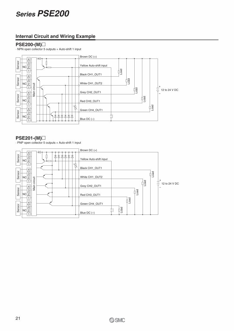
Internal Circuit and Wiring Example
PSE200-(M)�· NPN open collector 5 outputs + Auto-shift 1 input
PSE201-(M)�· PNP open collector 5 outputs + Auto-shift 1 input
21
Series PSE200
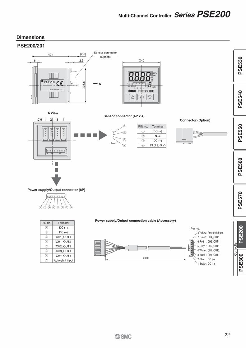
22
Multi-Channel Controller Series PSE200
2000
Pin no.8 Yellow : Auto-shift input
7 Green : CH4_OUT1
6 Red : CH3_OUT1
5 Grey : CH2_OUT1
4 White : CH1_OUT2
3 Black : CH1_OUT1
2 Blue : DC (–)
1 Brown : DC (+)
iy utrewq
�40
CH
kPaMPa
SET
4321OUT2OUT1
PRESSUREMADE IN JAPAN
PSE200
ZZ
6
40.1
2.5
�36
.8
r
e
w
q
(7.5) Sensor connector(Option)
Power supply/Output connector (8P)
1CH 2 3 4
A
A View
Dimensions
PSE200/201
Sensor connector (4P x 4)Connector (Option)
Power supply/Output connection cable (Accessory)PIN no. Terminal
DC (+)
DC (–)
CH1_OUT1
CH1_OUT2
CH2_OUT1
CH3_OUT1
CH4_OUT1
Auto-shift input
PIN no. Terminal
DC (+)
N.C.
DC (–)
IN (1 to 5 V)
PS
E53
0P
SE
540
PS
E55
0P
SE
560
PS
E57
0P
SE
200
PS
E30
0Con
trol
ler

23
Series PSE200
PRESSURE
OUT1OUT2
1 2 3 4
SET
MPakPa
CH
53
47
�42.4
Front protective cover
Waterproof seal Panel
Panel mount adapter
(2)
46.4
9.4
PRESSURE
OUT1OUT2
1 2 3 4
SET
MPakPa
CH
�48
Waterproof seal
�48 conversion adapter
Panel
Panel mount adapter
(2)
1.5
6
55 or more
4 x R1 or less
37.5 +0.1–0.2
55 o
r m
ore
Dimensions
Front protective cover + Panel mount adapter
�48 conversion adapter + Panel mount adapter
Panel fitting dimensionsApplicable panel thickness: 0.5 to 8 mm

SET
MPaPRESSURE
SET
MPaPRESSURE
SET
MPaPRESSURE
OUT1 OUT2OUT1 OUT2OUT1 OUT2
30 mm
Power supply/Output connector
Sensor connector
connector
PSE31(Current input type)
Electrical current input (4 to 20 mA DC) is added to the sensor input.
Applicable sensor typePSE550-28(Current output type)
Applicable sensor typePSE56 - -28(Current output type)
Applicable sensor typePSE57 - -28(Current output type)
®
Series PSE300
2-Colour Display DigitalPressure Sensor Controller
Response time
� Functions• Auto-shift function• Auto-preset function• Display calibration function• Peak/Bottom values holding/display function• Keylock function• Zero-clear function• Error indication function• Display unit switching function• Anti-chattering function
Possible to set 4 patterns of display colour. Possible to reduce panel fi tting labour.
2-colour display (Red/Green)
Connector type
Can be mounted in close proximity with each other either horizontally or vertically.
1 ms
DIN rail/Terminal block type Current input type
RoHS
Pattern ON OFFq Red Greenw Green Rede Red Redr Green Green
Applicable sensors Rated pressure range Set/Displayresolution
PSE53� PSE54� PSE55� PSE56� PSE57� −100 kPa 0 100 kPa 500 kPa 1 MPa
PSE531 PSE541 — PSE561 — –101 kPa 0 0.1 kPa
PSE533 PSE543 — PSE563 PSE573 –100 kPa 100 kPa 0.2 kPa
PSE530 PSE540 — PSE560 PSE570 0 1 MPa 0.001 MPa
PSE532 — — — — 0 100 kPa 0.1 kPa
— — — PSE564 PSE574 0 500 kPa 1 kPa
— — PSE550 — — 0 2 kPa 0.01 kPa
2424
PS
E53
0P
SE
540
PS
E55
0P
SE
560
PS
E57
0P
SE
200
PS
E30
0Con
trol
ler

25
Power supply/Output connection cableZS-28-A
Front protective cover
Sensor connector(e-con connector)
M3 x 5L
Bracket
M3 x 5L
Panel
Panel mount adapter
Mounting screw(M3 x 8L)
Panel
Panel mount adapter
Front protective cover
Mounting screw(M3 x 8L)
PSE3 0 M
PSE3 0
0
0 MT
Input specifications
Unit specifications— With display unit switching functionM Fixed SI unit Note 1)
Option 3
Option 2
Option
Note) The connector is not attached to the cable, but is included with the shipment.
Note) These options are not attached to products, but are included with the shipment.
DIN rail/Terminalblock type
Connector type
Order DIN rail separately. Refer to page 30.
Option/Part No.
Option 1
Input/Output specifications
Note 1) Fixed unitFor vacuum, low pressure, low differential pressure and compound pressure: kPaFor positive pressure: MPa (For 1 MPa) kPa (For 500 kPa)
Note) The cable is not attached to the product, but is included with the shipment.
Series PSE300Pressure Sensor Controller
How to Order
®
RoHS
— None
E
Front protective cover
0 NPN 2 outputs + 1-5 V output1 NPN 2 outputs + 4-20 mA output2 NPN 2 outputs + Auto-shift input3 PNP 2 outputs + 1-5 V output4 PNP 2 outputs + 4-20 mA output5 PNP 2 outputs + Auto-shift input
— None
L
Power supply/Output connection cable
Description Part no. Note
Power supply/Output connection cable (2 m) ZS-28-A
Bracket ZS-28-B With M3 x 5L (2 pcs.)
Sensor connector ZS-28-C 1 pc.
Panel mount adapter ZS-27-C With M3 x 8L (2 pcs.)
Panel mount adapter + Front protective cover ZS-27-D With M3 x 8L (2 pcs.)
Front protective cover ZS-27-01 1 pc.
0 Voltage input1 Current input
— None
A
Bracket
B
Panel mount adapter
D
Panel mount adapter + Front protective cover
— None
C
Sensor connector

For Pressure Switch Precautions and Specifi c Product Precautions, refer to “Handling Precautions for SMC Products” and the Operation Manual on SMC website.
26
Pressure Sensor Controller Series PSE300
10.6
Differentialpressure
5
AC
EF
BD
Ana
logu
e ou
tput
[V]
42.4
Differentialpressure
20
AC
EF
BD
Ana
logu
e ou
tput
[mA
]
Specifications
Analogue Output
Note 1) Pressure range can be selected during initial setting.Note 2) Auto-shift function is not available when analogue output option is selected. Also, analogue output option is not available when auto-shift function is selected. Extension analogue output is not available for the PSE570 series.
Note 3) The following units can be selected with display unit switching function:For vacuum & compound pressure: kPa·kgf/cm2·bar·psi·mmHg·inHgFor positive pressure & low pressure: MPa·kPa·kgf/cm2·bar·psiFor low differential pressure: kPa·mmH2O
1 to 5 V DC 4 to 20 mA DCRange Rated pressure range A B E
For vacuum 0 to –101 kPa 0 –101 kPa 10.1 kPaFor compound pressure –100 kPa to 100 kPa –100 kPa 100 kPa —
For low pressure 0 to 100 kPa 0 100 kPa –10 kPa
For positivepressure
0 to 1 MPa 0 1 MPa –0.1 MPa0 to 500 kPa 0 500 kPa –50 kPa
Model PSE3��
Applicable pressure sensor
PSE533PSE543PSE563PSE573
PSE531PSE541PSE561
PSE532
PSE530PSE540PSE560PSE570
PSE564PSE574 PSE550
Display/Set pressure (differential pressure) range –101 to 101 kPa 10 to –101 kPa –10 to 100 kPa –0.1 to 1 MPa –50 to 500 kPa –0.2 to 2 kPaDisplay/Set resolution 0.2 kPa 0.1 kPa 0.1 kPa 0.001 MPa 1 kPa 0.01 kPaPressure range Note 1) For compound pressure For vacuum For low pressure For positive pressure For low differential pressureRated pressure (differential pressure) range –100 to 100 kPa 0 to –101 kPa 0 to 100 kPa 0 to 1 MPa 0 to 500 kPa 0 to 2 kPaExtension analogue output range Note 2) — 10.1 to 0 kPa –10 to 0 kPa –0.1 to 0 MPa –50 to 0 kPa –0.2 to 0 kPaPower supply voltage 12 to 24 V DC ±10 %, Ripple (p-p) 10 % or less (with reverse connection protection)Current consumption 50 mA or less (Current consumption for sensor is not included.)
Sensor input PSE30�: Voltage input 1 to 5 V DC (Input impedance: 1 MΩ)PSE31�: Current input 4 to 20 mA DC (Input impedance: 100 Ω)
Number of inputs 1 inputInput protection With excess voltage protection (Up to 26.4 V)
Hysteresis Hysteresis mode: Variable, Window comparator mode: VariableSwitch output NPN or PNP open collector output: 2 outputs
Maximum load current 80 mAMaximum load voltage 30 V DC (at NPN output)Residual voltage 1 V or less (with load current of 80 mA)Output protection With short circuit protection
Response time 1 ms or lessAnti-chattering function Response time settings for anti-chattering function: 20 ms, 160 ms, 640 ms, 1280 ms
Repeatability ±0.1 % F.S.
Analogue output
Voltage output Note 2) Output voltage: 1 to 5 V (within rated pressure (differential pressure) range), 0.6 to 1 V (within extension analogue output range)Output impedance: Approx. 1 kΩ, Linearity: ±0.2 % F.S. (Not including sensor accuracy), Response speed: 150 ms or less
Accuracy (To display value) (25 °C) ±0.6 % F.S. ±1.0 % F.S. ±1.5 % F.S.
Current output Note 2)Output current: 4 to 20 mA (within rated pressure (differential pressure) range), 2.4 to 4 mA (within extension analogue output range)
Maximum load impedance: 300 Ω (at 12 V DC), 600 Ω (at 24 V DC), Minimum load impedance: 50 ΩLinearity: ±0.2 % F.S. (Not including sensor accuracy), Response time: 150 ms or less
Accuracy (To display value) (25 °C) ±1.0 % F.S. ±1.5 % F.S. ±2.0 % F.S.Display accuracy(Ambient temperature at 25 °C)
±0.5 % F.S.±2 digits ±0.5 % F.S. ±1 digit
Display 3 + 1/2 digit, 7 segment indicator, 2-colour display (Red/Green), Sampling frequency: 5 times/secIndicator light OUT1: Lights up when turned ON (Green), OUT2: Lights up when turned ON (Red)Auto-shift input Note 2) Non-voltage input (Reed or Solid state), Low level input: 5 ms or more, Low level: 0.4 V or less
En
viro
nm
ent Enclosure IP40
Operating temperature range Operating: 0 to 50 °C, Stored: –10 to 60 °C (No freezing or condensation)Operating humidity range Operating/Stored: 35 to 85 % RH (No condensation)Withstand voltage 1000 V AC for 1 minute between terminals and housingInsulation resistance 50 MΩ or more (500 V DC measured via megohmmeter) between terminals and housing
Temperature characteristics ±0.5 % F.S. (25 °C reference)
ConnectionPSE3��: Power supply/Output connection: 5P connector, Sensor connection: 4P connectorPSE3��T: Terminal block
Material Front case: PBT, Rear case: PBT (PSE3��), Modified PPE (PSE3��T)
WeightWith power supply/Output connection cable PSE3��: 85 gWithout power supply/Output connection cable PSE3��: 30 g, PSE3��T: 50 g
Power supply/Output connection cable Oilproof heavy-duty vinyl cable, 5 cores, Ø 4.1, 2 m, Conductor area: 0.2 mm2 Insulator O.D.: 1.12 mmStandards CE, UL/CSA (E216656), RoHS
Range Rated pressure range C D FFor low differential pressure 0 to 2 kPa 0 2 kPa –0.2 kPa
PS
E53
0P
SE
540
PS
E55
0P
SE
560
PS
E57
0P
SE
200
PS
E30
0Con
trol
ler

Brown DC (+)
Black OUT1
White OUT2
Blue DC (–)
Grey Analogue output
U
U
+
–
12 to
24 V DC
Mai
n ci
rcui
t
Load
Load
Load
Brown DC (+)
Black OUT1
White OUT2
Blue DC (–)
Grey Analogue output
U
U
+
–
12 to
24 V DC
Mai
n ci
rcui
t
Load
Load
Load
Brown DC (+)
Black OUT1
White OUT2
Blue DC (–)
Grey Auto-shift input
U
U
+
–
12 to
24 V DC
Mai
n ci
rcui
t
Load
Load
Brown DC (+)
Black OUT1
White OUT2
Blue DC (–)
Grey Analogue output
U
U
+
–
12 to
24 V DC
Mai
n ci
rcui
t
Load
Load
Load
Brown DC (+)
Black OUT1
White OUT2
Blue DC (–)
Grey Analogue output
U
U
+
–
12 to
24 V DC
Mai
n ci
rcui
t
Load
Load
Load
Brown DC (+)
Black OUT1
White OUT2
Blue DC (–)
Grey Auto-shift input
U
U
+
–
12 to
24 V DC
Mai
n ci
rcui
t
Load
Load
Internal Circuit and Wiring Example
PSE3�0(T)NPN (2 outputs) + Analogue voltage output
PSE3�2(T)NPN (2 outputs) + Auto-shift 1 input
PSE3�4(T)PNP (2 outputs) + Analogue current output
PSE3�1(T)NPN (2 outputs) + Analogue current output
PSE3�3(T)PNP (2 outputs) + Analogue voltage output
PSE3�5(T)PNP (2 outputs) + Auto-shift 1 input
PSE3 (T)
Input specifi cation
Input/Output specifi cation
Connector for Sensor Connection
PINno.
Terminal
PSE30�(Voltage input)
PSE31� (Current input)
Pressure sensor 2-wire type Pressure sensor 3-wire type
1 DC (+) (Brown) DC (+) (Brown) DC (+) (Brown)
2 N.C. N.C. N.C.
3 DC (–) (Blue) N.C. DC (–) (Blue)
4 IN (1 to 5 V) (Black) IN (4 to 20 mA) (Blue) IN (4 to 20 mA) (Black)
Note: The colours in ( ) indicate the wire colour of the PSE5�� series.
27
Series PSE300

28
Pressure Sensor Controller Series PSE3001.
5
depth 42 x M3 x 0.5
20 ±0.1 �30
10
8.2
3.21.5
331
Power supply/Output connector
Sensor connector
DC (+) Brown 5OUT1 Black 4OUT2 White 3
Analogue output or auto-shift input Grey 2DC (–) Blue 120
2020
4 3
2 1
1.6
40
Bracket
26.5
30
20
31.5
A
41
4.2
10
15
46
22
35
7
Panel mount adapter
�34.5247
8.5Panel thickness 0.5 to 6
42.4
Panel mount adapter + Front protective cover
�34.52411
Note: The colours in ( ) indicate the wire colour of the PSE5�� series.
Sensor connector
A View
Dimensions
With bracket
With panel mount adapter With panel mount adapter + Front protective cover
Power supply/Output connection cable (ZS-28-A)
PINno.
TerminalPSE30� PSE31�
1 DC(+)(Brown) DC(+)(Brown)2 N.C. N.C.3 DC(–)(Blue) N.C.4 IN (1 to 5 V) (Black) IN (4 to 20 mA) (Blue)
PSE3��
PS
E53
0P
SE
540
PS
E55
0P
SE
560
PS
E57
0P
SE
200
PS
E30
0Con
trol
ler

24 o
r m
ore
3131 x n pcs. + 3.5 x (n pcs. – 1)
0 –0.4
4 x R2 or less
4 x R2 or less
31
310 –0
.4
0–0.4
24 or more
4 x R2 or less
31 x
n p
cs. +
3.5
x (
n pc
s. –
1)
31 0–0.4
Panel fitting dimensions
Dimensions
Mount of single unit
Horizontal stacking mount of multiple units (n pcs.)
Vertical stacking mount of multiple units (n pcs.)
29
Series PSE300

30
Pressure Sensor Controller Series PSE300
PRESSURE
OUT1 OUT2
SET
5 6 7 8
1 2 3 4
3 x 7.2 (= 21.6)
38
6.4
8 x M3
2 x Ø 3.4 mounting hole
2 x Ø 6.4
10
56 44 �30
4.5
(Max
. 8)
11
29
42.4
�33
.5Front protective cover (Option)
(Rotate 90° to mount.)
35.5
28
16
1.5
21.4
34.8
38.6
(38.9)
Pressure sensor
Brown Black
FUNC(Analogueoutput or auto-shift input)
DC (–)INDC (+)
12 to24 V DC OUT1 OUT2 GND
Blue
+ –
Pressure sensor
Brown Blue
FUNC(Analogueoutput or auto-shift input)
DC (–)INDC (+)
12 to24 V DC OUT1 OUT2 GND
+ –
5.5
8 4.51.25
L
7.5
35 35
Connections
DIN Rail
ISA-5-�
PSE3��T
PSE3��T (Voltage input, Current input: Pressure sensor 3-wire type)
PSE31�T(Current input: Pressure sensor 2-wire type)
Dimensions
Part no. LISA-5-1 73.0
ISA-5-2 135.5
ISA-5-3 173.0
ISA-5-4 210.5
ISA-5-5 248.0
ISA-5-6 285.5
ISA-5-7 323.0
PS
E53
0P
SE
540
PS
E55
0P
SE
560
PS
E57
0P
SE
200
PS
E30
0Con
trol
ler

(P-3)P-1
ON
OFF
Hi
Lo
H-1(H-2)
A B
Supply pressurenormal
(Diff
eren
tial)
Pre
ssur
e
Rec
tifie
dva
lueRectified value
Switchoutput1·(2)
Auto-shiftinput
Supply pressuredrop
Supply pressureincrease
Switch output response time when auto- shift is input.
Max. A
P-1
P-2
Min. B
H-1
Work 1 Work 2
Work 1 Work 2 Work n
Work n
HighVacuum
Atmosphere
Adsorption
Non-adsorption
Load
Load
Brown DC (+)
Black
Blue DC (−)
WhiteOUT1OUT2
12
to 24 V DC
Grey Auto-shift input
+
−
Pressure sensor controller
Load
Load
12
to 24 V DC
+
−
Pressure sensor controller
Brown DC (+)
Black
Blue DC (−)
White
OUT1
OUT2
Grey Auto-shift input
Auto-shift circuitPSE3�2NPN open collector output: 2 outputs
PSE3�5PNP open collector output: 2 outputs
Note) The colours in the circuit diagram indicate the colour of the lead wire when it is connected to the power supply/output connection cable (ZS-28-A).
Function Details
A Auto-shift functionWhen there are large fluctuations in the supply pressure, the switch may fail to operate correctly. The auto-shift function compensates such supply pressure fluctuations. It measures the (differential) pressure at the time of auto-shift signal input and uses it as the reference (differential) pressure to correct the set value on the switch.
Set value correction by auto-shift function
∗ Rectified valueWhen the auto-shift is selected, “ooo” will be displayed for approxi-mately 1 second, and the pressure value at that point will be saved as a rectified value “C_5” (for CH1 of PSE200 and PSE300) or “C_3” (for CH2 to 4 for PSE200). Based on the saved rectified values (Note), the set value “P_1” to “P_4” (for PSE200) or “P_1”, “H_1”, “P_3”, “H_2” (for PSE300) will likewise be rectified.
Note) When an output is reversed, “n_1” to “n_4” (for PSE200) or “n_1”, “H_1”, “n_3”, “H_2” (for PSE300) will be rectified.
Auto-shift zero (PSE300 series only) The basic function of auto-shift zero is the same as the function for auto-shift. Also, it corrects values on the display, based on a pres-sure value of 0, when the auto-shift is selected.
Settable Range for Auto-Shift Input
B Auto-preset functionAuto-preset function, when selected in the initial setting, calculates and stores the set-value from the measured (differential) pressure.The optimum set-value is determined automatically by repeating vacuum and break with the target workpiece several times.
Suction Verification
Formula for Obtaining the Set Value
P_1 or P_3 P_2(H_1) or P_4(H_2)
PSE200P_1(P_3)=A-(A-B)/4
P_2(P_4)=B+(A-B)/4
PSE300 H_1(H_2)=(A-B)/2
A Auto-shift inputtime
B Switch output response timeat time of auto-shift input
PSE200 10 ms or more 15 ms or less
PSE300 5 ms or more 10 ms or less
PSE300 Set pressure(differential pressure) range Settable range
Compound pressure –101.0 to 101.0 kPa –101.0 to 101.0 kPa
Vacuum 10.0 to –101.0 kPa 101.0 to –101.0 kPa
Low pressure –10 to 100.0 kPa –100.0 to 100.0 kPa
Positive pressure–0.1 to 1.000 MPa –1.000 to 1.000 MPa
–50 to 500 kPa –500 to 500 kPa
Low differential pressure –0.2 to 2.00 kPa –2.00 to 2.00 kPa
PSE200 Set pressure(differential pressure) range Settable range
Compound pressure –101.0 to 101.0 kPa –101.0 to 101.0 kPa
Vacuum 10.0 to –101.0 kPa 101.0 to –101.0 kPa
Low pressure –10.0 to 101.0 kPa –100.0 to 101.0 kPa
Positive pressure–0.1 to 1.000 MPa –1.000 to 1.000 MPa
— —
Low differential pressure — —
31
Series PSE200/300
32
Pressure Sensor Controller Series PSE200/300
0 Applied pressure
Indicated value at the time of shipment
Adjustable range of display calibration function
±5 %R.D.
Indi
cate
d va
lue
of p
ress
ure
+
Pressure Momentary change
t (ms) t (ms) Time
<Averaging> <Averaging>
Set-valueP-1
H-1
Time
Time
Switch outputoperation in
normalconditions
ON
OFF
Switch outputoperation whenanti-chatteringfunction is on
ON
OFF
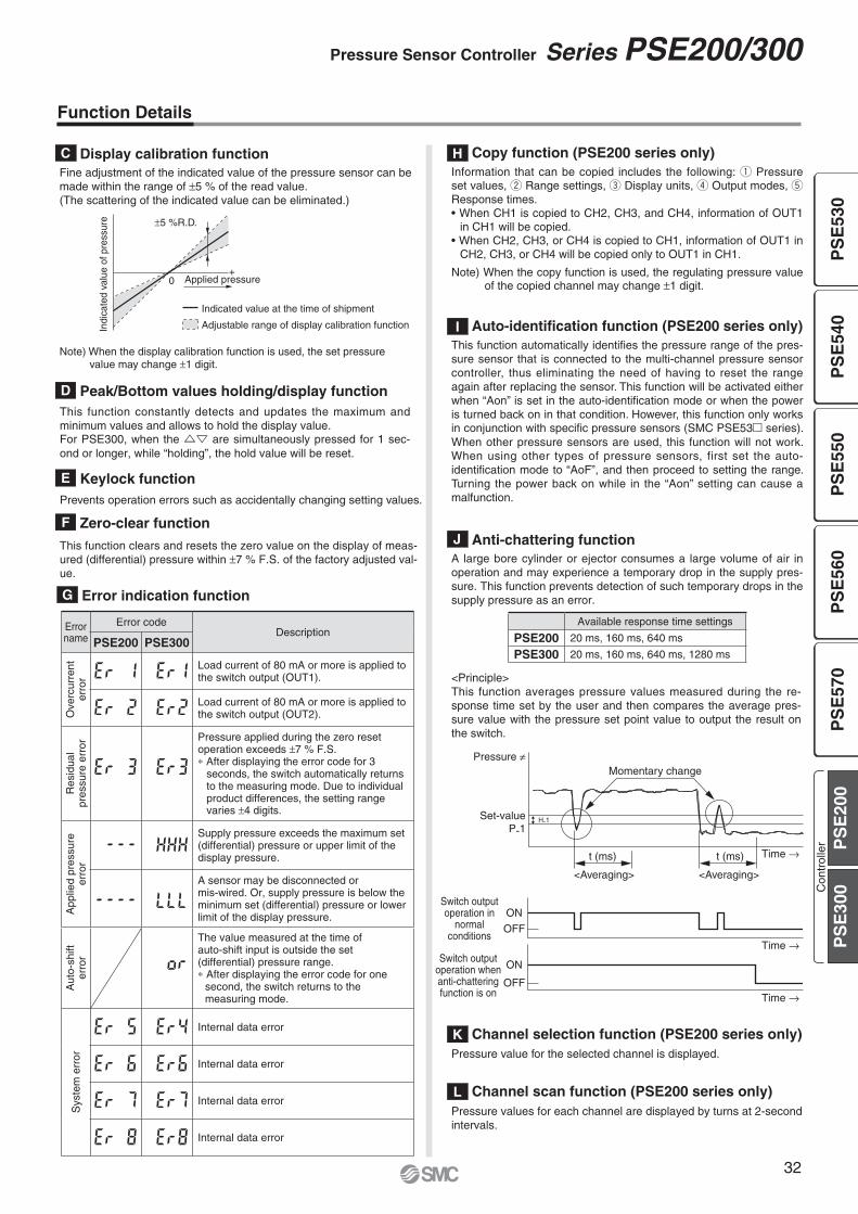
Function Details
G Error indication function
H Copy function (PSE200 series only)Information that can be copied includes the following: q Pressure set values, w Range settings, e Display units, r Output modes, t Response times.• When CH1 is copied to CH2, CH3, and CH4, information of OUT1
in CH1 will be copied.• When CH2, CH3, or CH4 is copied to CH1, information of OUT1 in
CH2, CH3, or CH4 will be copied only to OUT1 in CH1.
Note) When the copy function is used, the regulating pressure value of the copied channel may change ±1 digit.
I Auto-identification function (PSE200 series only)This function automatically identifies the pressure range of the pres-sure sensor that is connected to the multi-channel pressure sensor controller, thus eliminating the need of having to reset the range again after replacing the sensor. This function will be activated either when “Aon” is set in the auto-identification mode or when the power is turned back on in that condition. However, this function only works in conjunction with specific pressure sensors (SMC PSE53� series). When other pressure sensors are used, this function will not work. When using other types of pressure sensors, first set the auto-identification mode to “AoF”, and then proceed to setting the range. Turning the power back on while in the “Aon” setting can cause a malfunction.
K Channel selection function (PSE200 series only)Pressure value for the selected channel is displayed.
L Channel scan function (PSE200 series only)Pressure values for each channel are displayed by turns at 2-second intervals.
J Anti-chattering functionA large bore cylinder or ejector consumes a large volume of air in operation and may experience a temporary drop in the supply pres-sure. This function prevents detection of such temporary drops in the supply pressure as an error.
<Principle>This function averages pressure values measured during the re-sponse time set by the user and then compares the average pres-sure value with the pressure set point value to output the result on the switch.
D Peak/Bottom values holding/display functionThis function constantly detects and updates the maximum and minimum values and allows to hold the display value.For PSE300, when the �� are simultaneously pressed for 1 sec-ond or longer, while “holding”, the hold value will be reset.
F Zero-clear function
This function clears and resets the zero value on the display of meas-ured (differential) pressure within ±7 % F.S. of the factory adjusted val-ue.
E Keylock functionPrevents operation errors such as accidentally changing setting values.
C Display calibration functionFine adjustment of the indicated value of the pressure sensor can be made within the range of ±5 % of the read value.(The scattering of the indicated value can be eliminated.)
Note) When the display calibration function is used, the set pressure value may change ±1 digit.
Available response time settings
PSE200 20 ms, 160 ms, 640 ms
PSE300 20 ms, 160 ms, 640 ms, 1280 ms
Errorname
Error codeDescription
PSE200 PSE300
Ove
rcur
rent
er
ror
Load current of 80 mA or more is applied to the switch output (OUT1).
Load current of 80 mA or more is applied to the switch output (OUT2).
Res
idua
lpr
essu
re e
rror
Pressure applied during the zero reset operation exceeds ±7 % F.S.∗ After displaying the error code for 3
seconds, the switch automatically returns to the measuring mode. Due to individual product differences, the setting range varies ±4 digits.
App
lied
pres
sure
er
ror
Supply pressure exceeds the maximum set (differential) pressure or upper limit of the display pressure.
A sensor may be disconnected or mis-wired. Or, supply pressure is below the minimum set (differential) pressure or lower limit of the display pressure.
Aut
o-sh
ifter
ror
The value measured at the time of auto-shift input is outside the set (differential) pressure range.∗ After displaying the error code for one
second, the switch returns to the measuring mode.
Sys
tem
err
or
Internal data error
Internal data error
Internal data error
Internal data error
PS
E53
0P
SE
540
PS
E55
0P
SE
560
PS
E57
0P
SE
200
PS
E30
0Con
trol
ler
33
Series PSE200/300
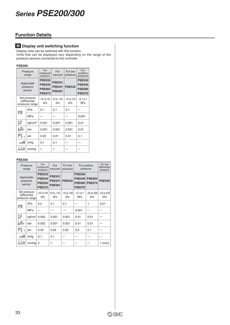
M Display unit switching functionDisplay units can be switched with this function.Units that can be displayed vary depending on the range of the pressure sensors connected to the controller.
PSE200
PSE300
Function Details
Pressurerange
Forcompoundpressure
Forvacuum
For lowpressure
For positivepressure
For lowdifferentialpressure
Applicablepressuresensor
PSE533
PSE543
PSE563
PSE573
PSE531
PSE541
PSE561
PSE532
PSE530
PSE540
PSE560
PSE570
PSE564
PSE574PSE550
Set pressure(differential
pressure) range
–101 to 101kPa
10 to –101kPa
–10 to 100kPa
–0.1 to 1MPa
–50 to 500kPa
–0.2 to 2.00kPa
kPa 0.2 0.1 0.1 — 1 0.01
MPa — — — 0.001 — —
kgf/cm2 0.002 0.001 0.001 0.01 0.01 —
bar 0.002 0.001 0.001 0.01 0.01 —
psi 0.05 0.02 0.02 0.2 0.1 —
inHg 0.1 0.1 — — — —
mmHg 2 1 — — — 1 mmH2O
Pressurerange
Forcompoundpressure
Forvacuum
For lowpressure
Forpositivepressure
Applicablepressuresensor
PSE533
PSE543
PSE563
PSE573
PSE531
PSE541
PSE561
PSE532
PSE530
PSE540
PSE560
PSE570
Set pressure(differential
pressure) range
–101 to 101kPa
10 to –101kPa
–10 to 101kPa
–0.1 to 1MPa
kPa 0.1 0.1 0.1 —
MPa — — — 0.001
kgf/cm2 0.001 0.001 0.001 0.01
bar 0.001 0.001 0.001 0.01
psi 0.02 0.01 0.01 0.1
inHg 0.1 0.1 — —
mmHg 1 1 — —


Lithuania +370 5 2308118 www.smclt.lt [email protected] +31 (0)205318888 www.smcpneumatics.nl [email protected] +47 67129020 www.smc-norge.no [email protected] +48 222119600 www.smc.pl [email protected] +351 226166570 www.smc.eu [email protected] +40 213205111 www.smcromania.ro [email protected] +7 8127185445 www.smc-pneumatik.ru [email protected] +421 (0)413213212 www.smc.sk [email protected] +386 (0)73885412 www.smc.si [email protected] +34 902184100 www.smc.eu [email protected] +46 (0)86031200 www.smc.nu [email protected] +41 (0)523963131 www.smc.ch [email protected] +90 212 489 0 440 www.smcpnomatik.com.tr [email protected] UK +44 (0)845 121 5122 www.smcpneumatics.co.uk [email protected]
Specifications are subject to change without prior notice and any obligation on the part of the manufacturer.SMC CORPORATION Akihabara UDX 15F, 4-14-1, Sotokanda, Chiyoda-ku, Tokyo 101-0021, JAPAN Phone: 03-5207-8249 FAX: 03-5298-5362
1st printing TT printing TU 00 Printed in Spain
Austria +43 (0)2262622800 www.smc.at [email protected] +32 (0)33551464 www.smcpneumatics.be [email protected] +359 (0)2807670 www.smc.bg [email protected] Croatia +385 (0)13707288 www.smc.hr [email protected] Republic +420 541424611 www.smc.cz [email protected] Denmark +45 70252900 www.smcdk.com [email protected] Estonia +372 6510370 www.smcpneumatics.ee [email protected] +358 207513513 www.smc.fi [email protected] +33 (0)164761000 www.smc-france.fr [email protected] +49 (0)61034020 www.smc.de [email protected] +30 210 2717265 www.smchellas.gr [email protected] +36 23511390 www.smc.hu [email protected] +353 (0)14039000 www.smcpneumatics.ie [email protected] +39 0292711 www.smcitalia.it [email protected] +371 67817700 www.smclv.lv [email protected]
Safety Instructions Be sure to read “Handling Precautions for SMC Products” (M-E03-3) before using.
SMC Corporation (Europe)
1. The compatibility of the product is the responsibility of the person who designs the equipment or decides its specifications.
Since the product specified here is used under various operating conditions, its compatibility with specific equipment must be decided by the person who designs the equipment or decides its specifications based on necessary analysis and test results. The expected performance and safety assurance of the equipment will be the responsibility of the person who has determined its compatibility with the product. This person should also continuously review all specifications of the product referring to its latest catalogue information, with a view to giving due consideration to any possibility of equipment failure when configuring the equipment.
2. Only personnel with appropriate training should operate machinery and equipment.
The product specified here may become unsafe if handled incorrectly. The assembly, operation and maintenance of machines or equipment including our products must be performed by an operator who is appropriately trained and experienced.
3. . Do not service or attempt to remove product and machinery/equipment until safety is confirmed.1. The inspection and maintenance of machinery/equipment should only be performed
after measures to prevent falling or runaway of the driven objects have been confirmed.
2. When the product is to be removed, confirm that the safety measures as mentioned above are implemented and the power from any appropriate source is cut, and read and understand the specific product precautions of all relevant products carefully.
3. Before machinery/equipment is restarted, take measures to prevent unexpected operation and malfunction.
4. Contact SMC beforehand and take special consideration of safety measures if the product is to be used in any of the following conditions. 1. Conditions and environments outside of the given specifications, or use outdoors or in
a place exposed to direct sunlight.2. Installation on equipment in conjunction with atomic energy, railways, air navigation,
space, shipping, vehicles, military, medical treatment, combustion and recreation, or equipment in contact with food and beverages, emergency stop circuits, clutch and brake circuits in press applications, safety equipment or other applications unsuitable for the standard specifications described in the product catalogue.
3. An application which could have negative effects on people, property, or animals requiring special safety analysis.
4. Use in an interlock circuit, which requires the provision of double interlock for possible failure by using a mechanical protective function, and periodical checks to confirm proper operation.
Warning Limited warranty and Disclaimer/Compliance Requirements The product used is subject to the following “Limited warranty and Disclaimer” and “Compliance Requirements”.Read and accept them before using the product.
1. The product is provided for use in manufacturing industries.The product herein described is basically provided for peaceful use in manufacturing industries. If considering using the product in other industries, consult SMC beforehand and exchange specifications or a contract if necessary. If anything is unclear, contact your nearest sales branch.
CautionSMC products are not intended for use as instruments for legal metrology.Measurement instruments that SMC manufactures or sells have not been qualified by type approval tests relevant to the metrology (measurement) laws of each country.Therefore, SMC products cannot be used for business or certification ordained by the metrology (measurement) laws of each country.
Caution
Limited warranty and Disclaimer1. The warranty period of the product is 1 year in service or 1.5 years
after the product is delivered, wichever is first.∗2)
Also, the product may have specified durability, running distance or replacement parts. Please consult your nearest sales branch.
2. For any failure or damage reported within the warranty period which is clearly our responsibility, a replacement product or necessary parts will be provided. This limited warranty applies only to our product independently, and not to any other damage incurred due to the failure of the product.
3. Prior to using SMC products, please read and understand the warranty terms and disclaimers noted in the specified catalogue for the particular products.
∗2) Vacuum pads are excluded from this 1 year warranty.A vacuum pad is a consumable part, so it is warranted for a year after it is delivered. Also, even within the warranty period, the wear of a product due to the use of the vacuum pad or failure due to the deterioration of rubber material are not covered by the limited warranty.
Compliance Requirements1. The use of SMC products with production equipment for the manufacture of
weapons of mass destruction (WMD) or any other weapon is strictly prohibited.
2. The exports of SMC products or technology from one country to another are governed by the relevant security laws and regulations of the countries involved in the transaction. Prior to the shipment of a SMC product to another country, assure that all local rules governing that export are known and followed.
These safety instructions are intended to prevent hazardous situations and/or equipment damage. These instructions indicate the level of potential hazard with the labels of “Caution,” “Warning” or “Danger.” They are all important notes for safety and must be followed in addition to International Standards (ISO/IEC)∗1), and other safety regulations.
∗1) ISO 4414: Pneumatic fluid power – General rules relating to systems. ISO 4413: Hydraulic fluid power – General rules relating to systems. IEC 60204-1: Safety of machinery – Electrical equipment of machines. (Part 1: General requirements) ISO 10218-1: Manipulating industrial robots - Safety. etc.
Caution indicates a hazard with a low level of risk which, if not avoided, could result in minor or moderate injury.
Warning indicates a hazard with a medium level of risk which, if not avoided, could result in death or serious injury.
Caution:
Warning:
Danger : Danger indicates a hazard with a high level of risk which, if not avoided, will result in death or serious injury.
Safety Instructions