Remote Relay Module (RRM)
13
Remote Relay Module (RRM) Instruction Manual WARNING THIS MANUAL MUST BE CAREFULLY READ BY ALL INDIVIDUALS WHO HAVE OR WILL HAVE THE RESPONSIBILITY FOR INSTALLING, USING OR SERVICING THIS PRODUCT. Like any piece of complex equipment, this product will perform as designed only if installed, used and serviced in accordance with the manufacturer’s instructions. OTHERWISE, IT COULD FAIL TO PERFORM AS DESIGNED AND PERSONS WHO RELY ON THIS PRODUCT FOR THEIR SAFETY COULD SUSTAIN SEVERE PERSONAL INJURY OR DEATH. The warranties made by Mine Safety Appliances Company with respect to these Products are voided if the products are not installed, used and serviced in accordance with the instructions in this user guide. Please protect yourself and others by following them. We encourage our customers to write or call regarding this equipment prior to use or for any additional information relative to use or repair. In North America., to contact your nearest stocking location, dial toll-free 1-800-MSA-INST To contact MSA International, dial (724) 776-8626 © MINE SAFETY APPLIANCES COMPANY 2012 - All Rights Reserved This manual is available on the internet at www.MSAsafety.com Manufactured by MSA NORTH AMERICA 1000 Cranberry Woods Drive, Cranberry Township, PA 16066 REV 1.4 March 2014 p/n 10155443
Transcript of Remote Relay Module (RRM)

Remote Relay Module (RRM)
Instruction Manual
WARNING
THIS MANUAL MUST BE CAREFULLY READ BY ALL INDIVIDUALS WHO HAVE OR WILL HAVE THE RESPONSIBILITY FOR INSTALLING, USING OR SERVICING THIS PRODUCT. Like any piece of complex equipment, this product will perform as designed only if installed, used and serviced in accordance with the manufacturer’s instructions. OTHERWISE, IT COULD FAIL TO PERFORM AS DESIGNED AND PERSONS WHO RELY ON THIS PRODUCT FOR THEIR SAFETY COULD SUSTAIN SEVERE PERSONAL INJURY OR DEATH. The warranties made by Mine Safety Appliances Company with respect to these Products are voided if the products are not installed, used and serviced in accordance with the instructions in this user guide. Please protect yourself and others by following them. We encourage our customers to write or call regarding this equipment prior to use or for any additional information relative to use or repair. In North America., to contact your nearest stocking location, dial toll-free 1-800-MSA-INST To contact MSA International, dial (724) 776-8626 © MINE SAFETY APPLIANCES COMPANY 2012 - All Rights Reserved This manual is available on the internet at www.MSAsafety.com Manufactured by
MSA NORTH AMERICA 1000 Cranberry Woods Drive, Cranberry Township, PA 16066
REV 1.4 March 2014 p/n 10155443
MSA Permanent Instrument Warranty
1. Warranty- Seller warrants that this product will be free from mechanical defect or faulty workmanship for a period of eighteen (18) months from date of shipment or one (1) year from installation, whichever occurs first, provided it is maintained and used in accordance with Seller’s instructions and/or recommendations. This warranty does not apply to expendable or consumable parts whose normal life expectancy is less than one (1) year such as, but not limited to, non-rechargeable batteries, filament units, filter, lamps, fuses etc. The Seller shall be released from all obligations under this warranty in the event repairs or modifications are made by persons other than its own or authorized service personnel or if the warranty claim results from physical abuse or misuse of the product. No agent, employee or representative of the Seller has any authority to bind the Seller to any affirmation, representation or warranty concerning the product. Seller makes no warranty concerning components or accessories not manufactured by the Seller, but will pass on to the Purchaser all warranties of manufacturers of such components. THIS WARRANTY IS IN LIEU OF ALL OTHER WARRANTIES, EXPRESSED, IMPLIED OR STATUTORY, AND IS STRICTLY LIMITED TO THE TERMS HEREOF. SELLER
SPECIFICALLY DISCLAIMS ANY WARRANTY OF MERCHANTABILITY OR OF FITNESS FOR A PARTICULAR PURPOSE. 2. Exclusive Remedy- It is expressly agreed that Purchaser’s sole and exclusive remedy for breach of the above warranty, for any tortious conduct of Seller, or for any other cause of action, shall be the repair and/or replacement at Seller’s option, of any equipment or parts thereof, which after examination by Seller is proven to be defective. Replacement equipment and/or parts will be provided at no cost to Purchaser, F.O.B. Seller’s Plant. Failure of Seller to successfully repair any nonconforming product shall not cause the remedy established hereby to fail of its essential purpose. 3. Exclusion of Consequential Damage- Purchaser specifically understands and agrees that under no circumstances will seller be liable to purchaser for economic, special, incidental or consequential damages or losses of any kind whatsoever, including but not limited to, loss of anticipated profits and any other loss caused by reason of non operation of the goods. This exclusion is applicable to claims for breach of warranty, tortuous conduct or any other cause of action against seller.

General Warnings
WARNING
1. The ZGARD CX II RRM Remote
Relay Module described in this manual must be installed, operated, and maintained in strict accordance with the labels, cautions, warnings, instructions, and within the limitations stated.
2. The ZGARD CX II RRM Remote
Relay Module must not be installed in outdoor areas or in locations where explosive concentrations of combustible gases or vapors might occur in the atmosphere: Class 1, Group A, B, C, and D areas as defined by the NEC. Because the controller is not explosion-proof, it must be located in non-hazardous areas.
3. Do not paint the ZGARD CX II RRM
Remote Relay Module.
4. The only absolute method to assure the proper overall operation of a gas detection instrument is to check it with a known concentration of the gas for which it has been calibrated. Consequently, a calibration check must be included as part of the installation and as a routine inspection of the system.
5. Use only genuine MSA replacement
parts when performing any maintenance procedures provided in this manual. Failure to do so may seriously impair instrument performance. Repair or alteration of the ZGARD CX II RRM Remote Relay Module, beyond the scope of these maintenance instructions or by anyone other than authorized MSA service personnel, could cause the product to fail to perform as designed, and persons who rely on this product for their safety could sustain serious personal injury or death.
6. The ZGARD CX II RRM Remote
Relay Module must be installed, located and operated in accordance to all applicable codes. These codes include, but are not limited to, the National Fire Prevention Code and National Electric Code.
7. Do not exceed the relay contact
ratings listed in this manual. Otherwise, the relay operation may fail, which can result in personal injury or death.
8. The ZGARD CX II Programmable Controller DOES NOT come pre-programmed with any sensor, relay or alarm setpoint parameters. These must be field-programmed and verified by trained and authorized personnel.
Failure to comply with the above warnings
can result in serious personal injury or death.
Table of Contents
Section 1 General Information and Specifications 1.0
Section 2 General Installation Guidelines 2.0
Section 3 Setup Configuration 3.0
Section 4 Operation and Features 4.0
Drawings
Section 1
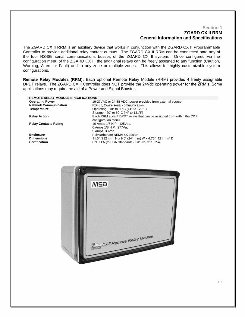
ZGARD CX II RRM General Information and Specifications
The ZGARD CX II RRM is an auxiliary device that works in conjunction with the ZGARD CX II Programmable Controller to provide additional relay contact outputs. The ZGARD CX II RRM can be connected onto any of the four RS485 serial communications busses of the ZGARD CX II system. Once configured via the configuration menu of the ZGARD CX II, the additional relays can be freely assigned to any function (Caution, Warning, Alarm or Fault) and to any zone or multiple zones. This allows for highly customizable system configurations. Remote Relay Modules (RRM): Each optional Remote Relay Module (RRM) provides 4 freely assignable DPDT relays. The ZGARD CX II Controller does NOT provide the 24Vdc operating power for the ZRM’s. Some applications may require the aid of a Power and Signal Booster.
REMOTE RELAY MODULE SPECIFICATIONS Operating Power 19-27VAC or 24-38 VDC, power provided from external source Network Communication RS485, 2-wire serial communication Temperature Operating: -10° to 50°C (14° to 122°F)
Storage: -20° to 60°C (-4° to 131°F) Relay Action Each RRM adds 4 DPDT relays that can be assigned from within the CX II
configuration menu. Relay Contacts Rating 10 Amps 1/8 H.P., 125Vac.
6 Amps 1/8 H.P., 277Vac. 5 Amps, 30Vdc.
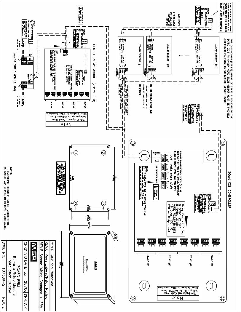
Enclosure Polycarbonate NEMA 4X design Dimensions 11.5” (292 mm) H x 9.5” (241 mm) W x 4.75” (121 mm) D Certification ENTELA (to CSA Standards) File No. 3118354
1.0
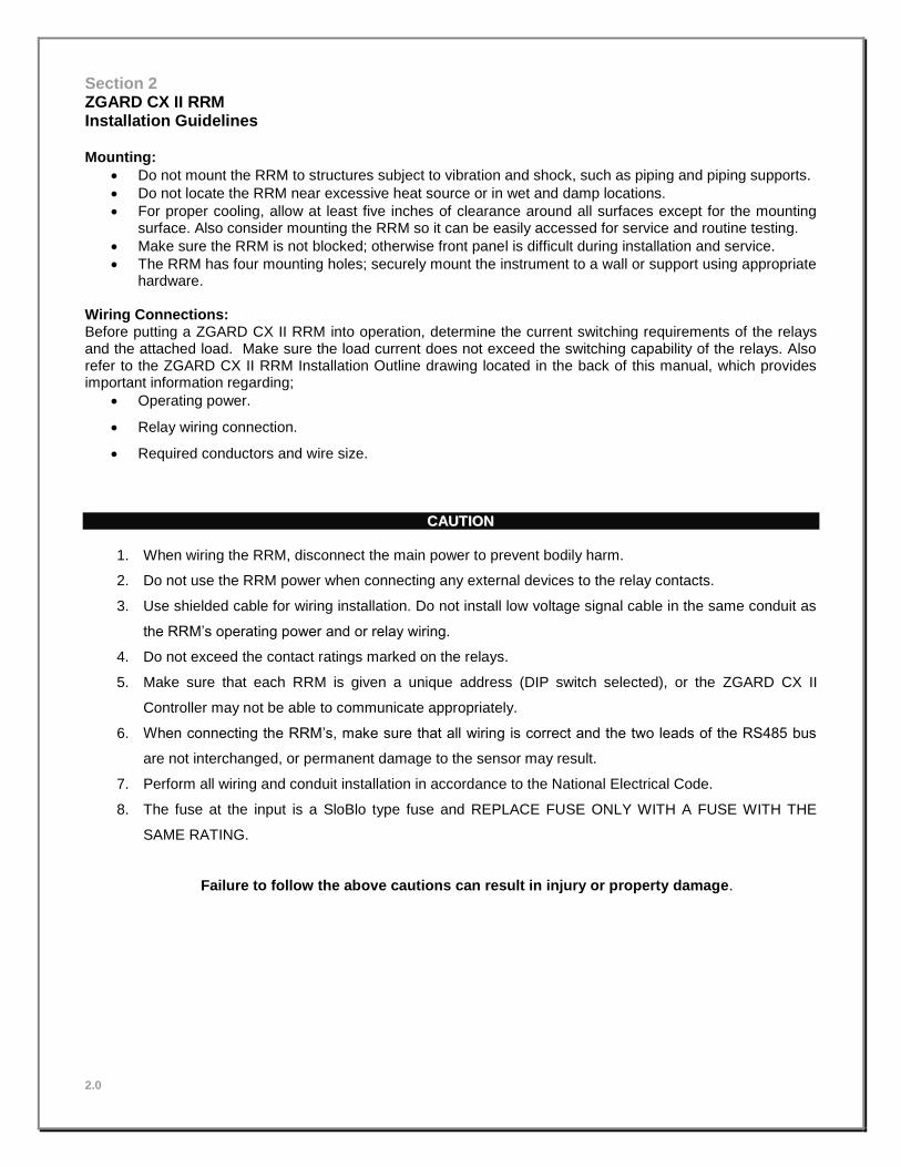
Section 2 ZGARD CX II RRM Installation Guidelines Mounting:
Do not mount the RRM to structures subject to vibration and shock, such as piping and piping supports.
Do not locate the RRM near excessive heat source or in wet and damp locations.
For proper cooling, allow at least five inches of clearance around all surfaces except for the mounting surface. Also consider mounting the RRM so it can be easily accessed for service and routine testing.
Make sure the RRM is not blocked; otherwise front panel is difficult during installation and service.
The RRM has four mounting holes; securely mount the instrument to a wall or support using appropriate hardware.
Wiring Connections: Before putting a ZGARD CX II RRM into operation, determine the current switching requirements of the relays and the attached load. Make sure the load current does not exceed the switching capability of the relays. Also refer to the ZGARD CX II RRM Installation Outline drawing located in the back of this manual, which provides important information regarding;
Operating power.
Relay wiring connection.
Required conductors and wire size.
CCAAUUTTIIOONN
1. When wiring the RRM, disconnect the main power to prevent bodily harm.
2. Do not use the RRM power when connecting any external devices to the relay contacts.
3. Use shielded cable for wiring installation. Do not install low voltage signal cable in the same conduit as
the RRM’s operating power and or relay wiring.
4. Do not exceed the contact ratings marked on the relays.
5. Make sure that each RRM is given a unique address (DIP switch selected), or the ZGARD CX II
Controller may not be able to communicate appropriately.
6. When connecting the RRM’s, make sure that all wiring is correct and the two leads of the RS485 bus
are not interchanged, or permanent damage to the sensor may result.
7. Perform all wiring and conduit installation in accordance to the National Electrical Code.
8. The fuse at the input is a SloBlo type fuse and REPLACE FUSE ONLY WITH A FUSE WITH THE
SAME RATING.
Failure to follow the above cautions can result in injury or property damage.
2.0

Section 3 ZGARD CX II RRM
Factory Setup Configuration Address Configuration:
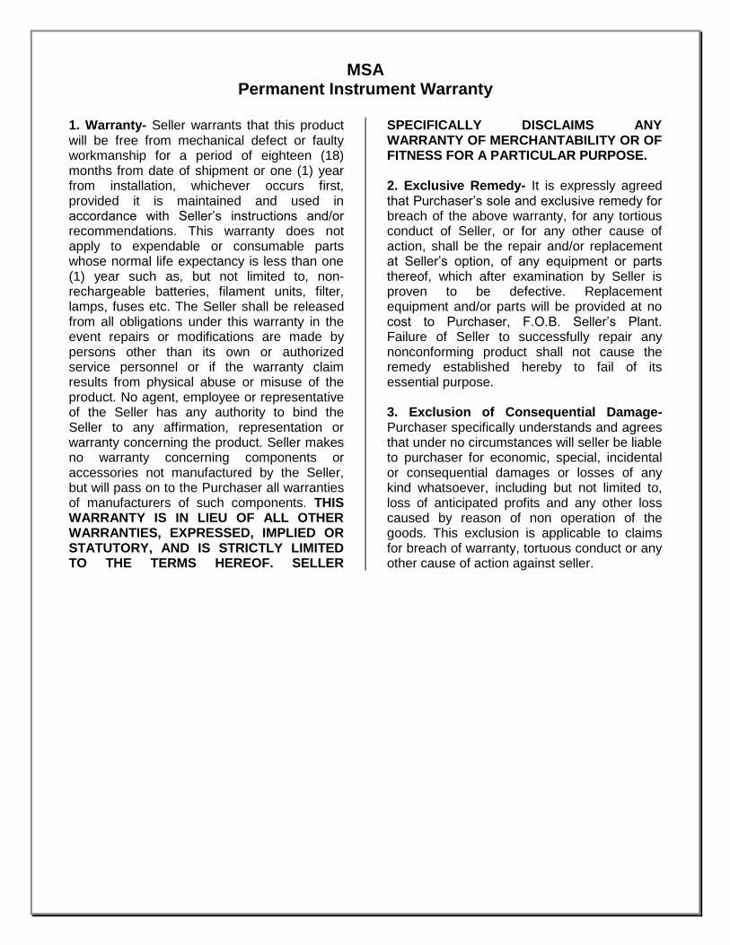
The ZGARD CX II RRM requires an address to be selected on SW1 so that it can be identified by the CX-II controller. The table below shows the address switch positions and the corresponding address (displayed as ‘relay card number’ in the CX-II relay setup menus) as well as the relay numbers as they are identified in the CX-II relay setup menus.
SW1-1 SW1-2 SW1-3 SW1-4 Address Relay Number in CX-II Controller
OFF OFF OFF OFF 0 1,2,3,4 (same as CX-II built-in relays)
ON OFF OFF OFF 1 5,6,7,8
OFF ON OFF OFF 2 9,10,11,12
ON ON OFF OFF 3 13,14,15,16
OFF OFF ON OFF 4 17,18,19,20
ON OFF ON OFF 5 21,22,23,24
OFF ON ON OFF 6 25,26,27,28
ON ON ON OFF 7 29,30,31,32
OFF OFF OFF ON 8 33,34,35,36
ON OFF OFF ON 9 37,38,39,40
Relay Fail Operation:
The ZGARD CX II RRM has an optional relay fail mode function that can set the relays to a known, user- selectable state if communication with the main CX-II controller is lost. This function has two parts: 1) enable and 2) fail state. The table below shows the various options:
Normal Relay Mode:
The ZGARD CX II RRM has an optional relay mode function that can operate the relays in a normally de-energized mode or a normally energized mode. In a normally de-energized operating mode, the relays remain de-energized until an alarm condition occurs on the CX-II at which point they become energized. In a normally energized operating mode, the relays remain energized until an alarm condition occurs on the CX-II at which point they become de-energized. The table below shows the various options:
3.0
SW1-5 SW1-6 Relay Operation during Communication Fail
OFF Don’t Care All 4 relays remain in last state (default) ON OFF All 4 relays de-energize ON ON All 4 relays energize
SW1-8 Normal Relay Mode
OFF All 4 relays normally de-energized (default)
ON All 4 relays normally energized

Section 4 ZGARD CX II RRM Operation and Features
Note: The ZGARD CX II Programmable Controller DOES NOT come pre-programmed with any sensor, relay or alarm setpoint parameters. These must be field-programmed and verified by trained and authorized personnel.
General: The ZGARD CX II RRM provides additional relays to a CX-II gas controller system. These relays are completely custom programmable from the CX-II main controller as to their function. The may be used individually to provide additional outputs at a zone level or they may be grouped together to provide higher control functions. See the CX-II controller manual for more details on relay programming.
Address Configuration: The ZGARD CX II RRM uses a DIP switch selectable address so that it can be identified by the CX-II controller. Each RRM adds four (4) additional relays to the relay setup menus on the CX-II menus. The cards address is displayed as ‘relay card number’ in the CX-II relay setup menus.
Communication Fail: The ZGARD CX II RRM has an optional relay fail mode function that can set the relays to a known, user- selectable state if communication with the main CX-II controller is lost. This function has two parts: 1) enable and 2) fail state. The function must first be enabled via SW1-5 and then the desired relay output must be selected using SW1-6.
Normal Relay Mode: The ZGARD CX II RRM has an optional relay mode function that can operate the relays in a normally de-energized mode or a normally energized mode. In a normally de-
energized operating mode, the relays remain de-energized until an alarm condition occurs on the CX-II at which point they become energized. In a normally energized operating mode, the relays remain energized until an alarm condition occurs on the CX-II at which point they become de-energized.
Test Mode: It is not recommended that the test mode be used except under instructions and guidance from a qualified factory representative. Enabling the test mode (SW1-7 = ON) can render the entire CX-II system inoperable and may cause false alarms or no alarms in the event of a gas presence.
The test mode turns the RRM card into an RS-485 output device by sending relay control signals on the RS-485 bus. This can be used to test another suspect RRM card.
NEVER activate the test mode while a RRM card is installed in a system.
System Diagnostics Feature: The ZGARD CX II RRM has three indicator lights on the left hand side near the bottom of the card. They are labelled ‘ACTIVE’, ‘RX’ and ‘TX’. The RX and TX lights indicate data traffic on the RS-485 bus. Once a RRM card has been configured in the CX II controller and the CX II controller is sending data to the card, the ACTIVE light will blink every time it receives valid data. If communication from the CX II should become lost, the ACTIVE light will begin a slow steady flash to indicate no communication.
4.
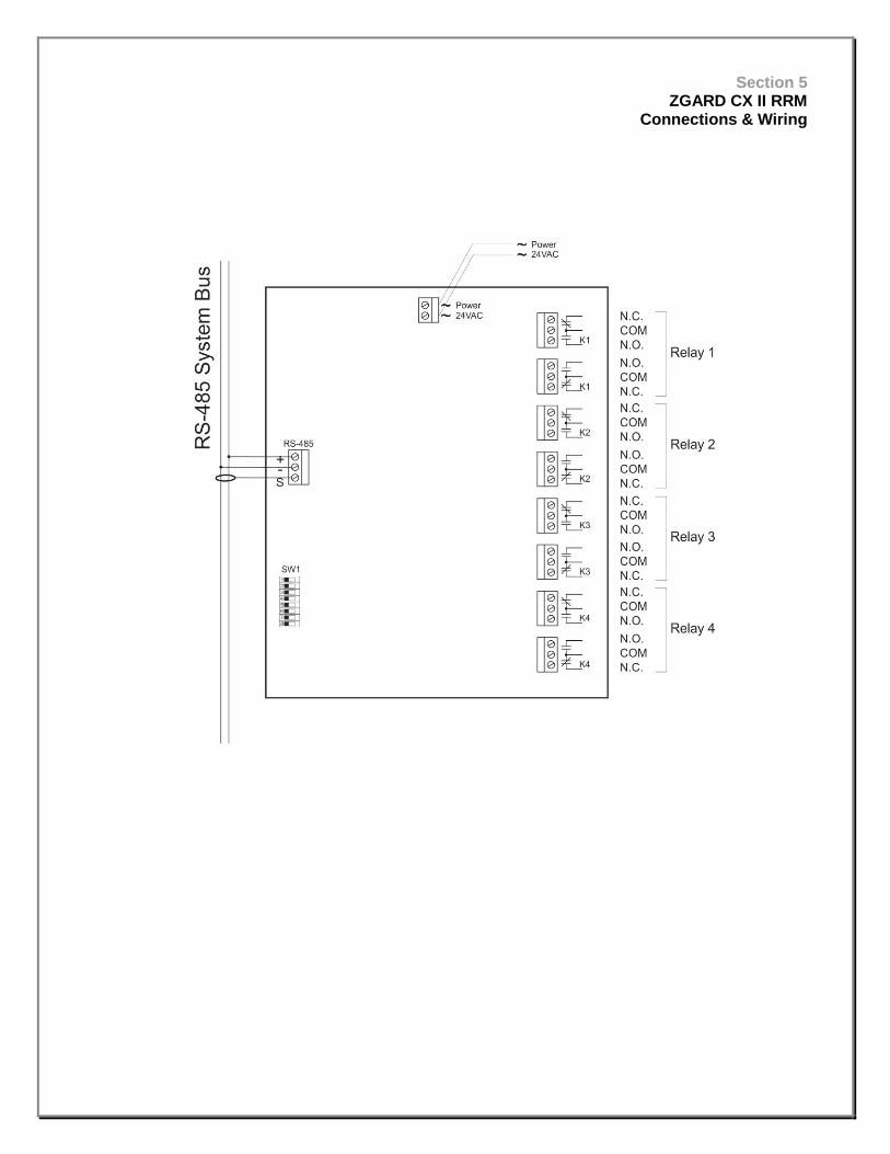
Section 5 ZGARD CX II RRM
Connections & Wiring

12345678
0
1
2
3
4
K1=
K2=
K3=
K4=
12345678
1
5
6
7
8
12345678
2
9
10
11
12
12345678
3
13
14
15
16
12345678
4
17
18
19
20
12345678
5
21
22
23
24
12345678
6
25
26
27
28
12345678
7
29
30
31
32
12345678
8
33
34
35
36
12345678
9
37
38
39
40
Relay
CardID &DIPSW
Note: Strobe Option
Powered from 24VAC only!Use only strobe:INGRAM model SB1224AD
12345678
De-Energize
12345678
Energize
12345678
LastState
Relay Card ID & Relay Numbers
12345678
NormalMode
12345678
TestMode
12345678
12345678
Relay StateOn Comm. Fail
(All Relays)
NormallyDe-
Energized
123456
8
Relay Card Operating Mode
123456
12345678
12345678
Relay Operating Mode
NormallyEnergized
Relay Card Test Mode
Copyright(c) 2014
DATE: DRN:
DWG. NO.:
REV DRN DESCRIPTION DATE
A DP Initial Release Feb 19/13
108710-B
Feb. 19/13 DP
Zgard CX-II & ZGARD RRMRatings, Caution & Configuration
Labels
ZGARD CX-II-B-0
Gas Monitoring Station
Power: 17-27VAC, 50/60Hz or 24-38VDC0.3Amp (0.7Amp with strobe, AC only)
Input: RS-485, 99 ZGARD Sensors max.Output: 4 Relays with 2 ‘C’ Contacts each
5A max. @ 250VAC or 30VDCwww.msasafety.comSerial No.: 000000-0
ZGARD RRM-xx-xx
Remote Relay Module
Power: 17-27VAC, 50/60Hz or 24-38VDC0.3Amp (0.7Amp with strobe, AC only)
Input: RS-485, 99 ZGARD Sensors max.Output: 4 Relays with 2 ‘C’ Contacts each
5A max. @ 250VAC or 30VDCwww.msasafety.comSerial No.: 000000-0 3118354
Intertek
ETL LISTEDCONFORMS TOUL 61010-1-2012
CERTIFIED TOCAN/CSA C22.2No. 61010-1-12
CM
CAUTION: BONDING BETWEEN CONDUIT CONNECTIONS ARE NOT AUTOMATIC AND MUST BE PROVIDED AS PART OF THE INSTALLATION
!This equipment could have voltages up to 250VAC present, from other devices, in other locations
!
B MG Moved to Corel Apr 1/14
CAUTION
Replacement BatteryManufacturer Model UL File #Panasonic CR2032 MH12210Energizer CR2032 MH29980Sony Corp. CR2032 MH12566
Label Technical Information:Material: 3M, 7840TLUL Recognized: MH16411Printer: HP LaserJet 4200Toner: Q1338A